optical thin film technology for ultrafast fiber lasers · if you believe that this document...
TRANSCRIPT

Tampere University of Technology
Optical Thin Film Technology for Ultrafast Fiber Lasers
CitationOrsila, L. (2008). Optical Thin Film Technology for Ultrafast Fiber Lasers. (Tampere University of Technology.Publication; Vol. 731). Tampere University of Technology.
Year2008
VersionPublisher's PDF (version of record)
Link to publicationTUTCRIS Portal (http://www.tut.fi/tutcris)
Take down policyIf you believe that this document breaches copyright, please contact [email protected], and we will remove access tothe work immediately and investigate your claim.
Download date:07.07.2018

Julkaisu 731 Publication 731
Lasse Orsila
Optical Thin Film Technology for Ultrafast Fiber Lasers
Tampere 2008

Tampereen teknillinen yliopisto. Julkaisu 731 Tampere University of Technology. Publication 731 Lasse Orsila Optical Thin Film Technology for Ultrafast Fiber Lasers Thesis for the degree of Doctor of Technology to be presented with due permission for public examination and criticism in Tietotalo Building, Auditorium TB104, at Tampere University of Technology, on the 25th of April 2008, at 12 noon. Tampereen teknillinen yliopisto - Tampere University of Technology Tampere 2008

ISBN 978-952-15-1955-0 (printed) ISBN 978-952-15-2018-1 (PDF) ISSN 1459-2045

ABSTRACT
This thesis investigates novel dispersion compensation methods for mode-lockedfiber lasers and the dynamical properties of ytterbium and thulium-holmium gainmaterials. The emphasis is on dielectric thin film structures and their integration intofiber cavities to control laser performance.
A Gires–Tournois interferometer (GTI) made with electron beam evaporation wasused for the first time to compensate for the dispersion of a fiber cavity and thusachieve ultrashort mode-locked pulses. Another thin film dispersion compensator, aFabry-Pérot etalon, demonstrated in a mode-locked fiber laser, allowed for contin-uously tunable short pulse operation of an ytterbium fiber laser over a broad wave-length range.
In addition to dispersive thin film structures, the thesis also presents a new type ofdichroic coating deposited directly onto an optical fiber end. The dichroic coatingacts as an output coupler and pump combiner, simultaneously. This enables lasercavities which are substantially shorter than would be possible with conventionalfiber components. The compact all-fiber ytterbium fiber laser presented had a recordhigh fundamental repetition rate of 571 MHz with ultrashort, 572 fs, pulses.
The energy level scheme of ytterbium and thulium-holmium gain materials was stud-ied for the first time in this thesis by analyzing the laser relaxation oscillations. Bothmaterials exhibited a change in transition mechanism from three-level to four-levellaser operation in the long-wavelength tail of the gain bandwidth.

ii Abstract

ACKNOWLEDGMENTS
The work presented in this thesis was carried out at the Optoelectronics ResearchCentre (ORC) at Tampere University of Technology from 2003 to 2007. I grate-fully acknowledge the financial support provided by the Graduate school of Elec-tronics, Telecommunication and Automation (GETA), by the Finnish Foundation forAdvanced Sciences (TES), by the Finnish Academy of Science and Letter’s Vilho,Yrjö and Kalle Väisälä Foundation, by the Jenny and Antti Wihuri Foundation, by theMagnus Ehrnrooth Foundation, by the European Commission through the URANUSand NATAL projects, and by the Academy of Finland through the Tule-QUESTproject.
I would like to thank my supervisor Professor Oleg Okhotnikov for his important rolein the research carried out in this thesis and his enthusiastic guidance of my work atORC, Professor Markus Pessa for giving me the opportunity to work at ORC and forthe continuous support along the way and Dr. Mircea Guina for guidance and valuablediscussions during the thesis. I must also remember to thank Anne Viherkoski for hergreat help along the way and for leveling bureaucratic obstacles.
I thank my excellent current and former colleagues Dr. Robert Herda, Dr. MateiRusu, Dr. Antti Isomäki, Dr. Luís Gomes, Dr. Claudio Porzi, M.Sc. Tommi Haku-linen, M.Sc. Samuli Kivistö, M.Sc. Esa Saarinen, M.Sc. Jussi Rautiainen and M.Sc.Juho Kerttula for fruitful co-operation during these many years. Moreover, I want toespecially thank Dr. Antti Härkönen for being my office mate and a friend during mytime at ORC.
I also want to thank the whole ORC research staff for supporting my work. Partic-ularly I want to mention the processing people Pirjo Leinonen and Jukka Viheriälä,MBE growers Jari Lyytikäinen, Tomi Leinonen and Soile Suomalainen, and AnttiTukiainen concerning material characterization. I also remember the help from myformer colleague Markus Peltola with the electron beam evaporator in the early stagesof the work and also Jari Näppi for valuable discussions and hints for thin film prob-lems.

iv Acknowledgments
My work at ORC has also benefited from co-operation with several companies in-cluding EpiCrystals, Fianium, Modulight, Nokia, Planar and RefleKron.
I thank Dr. Charis Reith for proofreading the thesis and giving valuable suggestionsand pre-examiners Dr. John Clowes and Dr. Sergey Vainshtein for comments andreview of my thesis.
I also want to thank my family and relatives, especially my parents-in-law, my par-ents, my wife Reetta and little Aino for support and motivation for my work.
Tampere, Finland, April 2008
Lasse Orsila

TABLE OF CONTENTS
Abstract . . . . . . . . . . . . . . . . . . . . . . . . . . . . . . . . . . . . i
Acknowledgments . . . . . . . . . . . . . . . . . . . . . . . . . . . . . . . iii
Table of Contents . . . . . . . . . . . . . . . . . . . . . . . . . . . . . . . v
List of Publications . . . . . . . . . . . . . . . . . . . . . . . . . . . . . . vii
Author’s contribution . . . . . . . . . . . . . . . . . . . . . . . . . . . . . ix
List of Abbreviations . . . . . . . . . . . . . . . . . . . . . . . . . . . . . . xi
1. Introduction . . . . . . . . . . . . . . . . . . . . . . . . . . . . . . . . 1
1.1 A brief history of optical thin films and fiber lasers . . . . . . . . . 1
1.1.1 Thin films . . . . . . . . . . . . . . . . . . . . . . . . . . . 1
1.1.2 Lasers . . . . . . . . . . . . . . . . . . . . . . . . . . . . . 2
1.1.3 Fiber lasers . . . . . . . . . . . . . . . . . . . . . . . . . . 3
1.2 State of the art . . . . . . . . . . . . . . . . . . . . . . . . . . . . . 4
1.3 Incentives and outline . . . . . . . . . . . . . . . . . . . . . . . . . 5
2. Optical thin films . . . . . . . . . . . . . . . . . . . . . . . . . . . . . . 7
2.1 Introduction to thin films . . . . . . . . . . . . . . . . . . . . . . . 7
2.2 Thin film properties . . . . . . . . . . . . . . . . . . . . . . . . . . 8
2.3 Mechanical properties of optical thin films . . . . . . . . . . . . . . 10
2.4 Manufacturing thin films . . . . . . . . . . . . . . . . . . . . . . . 11
2.5 Electron beam evaporation . . . . . . . . . . . . . . . . . . . . . . 12
2.6 Basic optical thin film theory . . . . . . . . . . . . . . . . . . . . . 13
2.7 Thin film design . . . . . . . . . . . . . . . . . . . . . . . . . . . . 19
2.7.1 Anti-reflection coatings . . . . . . . . . . . . . . . . . . . . 20

vi Table of Contents
2.7.2 High reflective coatings . . . . . . . . . . . . . . . . . . . 26
2.7.3 Dichroic coatings . . . . . . . . . . . . . . . . . . . . . . . 29
2.7.4 Dispersive mirrors . . . . . . . . . . . . . . . . . . . . . . 31
2.8 Summary . . . . . . . . . . . . . . . . . . . . . . . . . . . . . . . 37
3. Ytterbium mode-locked fiber lasers . . . . . . . . . . . . . . . . . . . . 39
3.1 Mode locking . . . . . . . . . . . . . . . . . . . . . . . . . . . . . 39
3.1.1 Active mode locking . . . . . . . . . . . . . . . . . . . . . 39
3.1.2 Passive mode locking . . . . . . . . . . . . . . . . . . . . . 40
3.2 Ytterbium fiber lasers . . . . . . . . . . . . . . . . . . . . . . . . . 41
3.2.1 Saturable absorbers . . . . . . . . . . . . . . . . . . . . . . 42
3.2.2 Fiber components . . . . . . . . . . . . . . . . . . . . . . . 43
3.3 Dispersion compensation techniques for the 1 µm region . . . . . . 44
3.4 GTI dispersion compensation . . . . . . . . . . . . . . . . . . . . . 47
3.5 Fabry–Pérot etalons for dispersion compensation . . . . . . . . . . 51
3.6 Summary . . . . . . . . . . . . . . . . . . . . . . . . . . . . . . . 53
4. Fiber laser dynamics and relaxation oscillations . . . . . . . . . . . . . . 55
4.1 Dynamics . . . . . . . . . . . . . . . . . . . . . . . . . . . . . . . 55
4.2 Relaxation oscillations . . . . . . . . . . . . . . . . . . . . . . . . 56
4.3 Ytterbium . . . . . . . . . . . . . . . . . . . . . . . . . . . . . . . 58
4.4 Thulium-holmium . . . . . . . . . . . . . . . . . . . . . . . . . . . 60
4.5 Summary . . . . . . . . . . . . . . . . . . . . . . . . . . . . . . . 62
5. High repetition rate short pulse fiber lasers . . . . . . . . . . . . . . . . . 63
5.1 Why high repetition rate? . . . . . . . . . . . . . . . . . . . . . . . 63
5.2 Dichroic fiber end facet coatings . . . . . . . . . . . . . . . . . . . 64
5.3 Compact fiber laser with photonic crystal fiber . . . . . . . . . . . . 68
5.4 Summary . . . . . . . . . . . . . . . . . . . . . . . . . . . . . . . 70
6. Conclusions . . . . . . . . . . . . . . . . . . . . . . . . . . . . . . . . 71
Bibliography . . . . . . . . . . . . . . . . . . . . . . . . . . . . . . . . . . 73

LIST OF PUBLICATIONS
This thesis contains the following six publications, which are included as appendices.In the text, these publications are referred to as [P1]. . . [P6]. In addition to this, thethesis contains new, unpublished material e.g. dispersion measurements that verifythe modeled dispersion curves presented in [P1] and [P2], and a novel dispersioncompensation scheme integrating a dispersive mirror into a prism.
[P1] L. A. Gomes, L. Orsila, T. Jouhti, and O. G. Okhotnikov, ”Picosecond SESAMbased ytterbium mode-locked fiber lasers,” IEEE Journal of Selected Topicsin Quantum Electronics, vol. 10, no. 1, issue on Ultrafast Science and Tech-nology, pp. 129–136, 2004.
[P2] L. Orsila, L. A. Gomes, N. Xiang, T. Jouhti, and O. G. Okhotnikov, ”Mode-locked ytterbium fiber lasers,” Applied Optics, vol. 43, no. 9, pp. 1902–1906,2004.
[P3] L. Orsila and O. G. Okhotnikov, ”Three- and four-level transition dynamicsin Yb-fiber laser,” Optics Express, vol. 13, no. 9, pp. 3218–3223, 2005.
[P4] L. Orsila, R. Herda, T. Hakulinen and O. G. Okhotnikov, ”Thin-film Fabry–Pérot dispersion compensator for mode-locked fiber lasers,” IEEE PhotonicsTechnology Letters vol. 19, no. 1, pp. 6–8, 2007.
[P5] L. Orsila, S. Kivistö, R. Herda and O. G. Okhotnikov, ”Spectroscopy of therelaxation dynamics in Tm-Ho-fiber lasers,” in Conference Digest of Euro-pean Conference on Lasers and Electro-Optics 2007, München, 20–25 June,2007, p. CE-24-TUE.
[P6] L. Orsila, R. Herda and O. G. Okhotnikov, ”Monolithic fiber mirror and pho-tonic crystal technology for high repetition rate all-fiber soliton lasers,” IEEEPhotonics Technology Letters, vol. 19, no. 24, pp. 2009–2011, 2007.

viii List of Publications
In addition to the papers included in this thesis, the following supplementary papersare related to this work but are not appended to this dissertation. In the text, thesepublications are referred to as [S1]. . . [S3]. I have also made contributions to otherpublications concerning thin films [1–12], optoelectronics [13–24] and fiber technol-ogy [25–27] but they are beyond the scope of this thesis.
[S1] L. Orsila, L. Gomes, O. G. Okhotnikov, ”Mode-locked ytterbium fiber laserdispersion compensation with Gires–Tournois interferometer,” in Proceed-ings of the Optics Days 2004, Turku, Finland, 6–7 May, 2004, p. 49.
[S2] L. Orsila, ”Economic thin film in-situ monitoring in electron-beam evapora-tion using optical fiber back reflection,” in Proceedings of the Optics Days2004, Turku, Finland, 6–7 May, 2004, p. 48.
[S3] L. Orsila, R. Herda, T. Hakulinen and O. G. Okhotnikov, ”Thin-film dis-persion compensator for mode-locked fiber lasers,” in Conference Digest ofEuropean Conference on Lasers and Electro-Optics, 2007, München, 20–25June, 2007, p. CF-21-MON.

AUTHOR’S CONTRIBUTION
This thesis includes six papers published in international peer-reviewed journals andscientific conferences. It also contains material from supplementary publications andnew unpublished results.
The work presented here is a result of teamwork. I have been directly responsiblefor designing and manufacturing the optical thin films presented in this thesis andbuilding several of the measurement systems presented here. I have also had a majorrole in writing the papers and carrying out most of the measurements presented inthis thesis and the included publications.
A summary of my contribution to the included papers is listed in Table 1 below.
Table 1: Author’s contribution to the papers and to the experimental research work.
Paper Contribution in experimental work Contribution in writing the paper
[P1] Group work (30 %) Co-author (20 %)
[P2] Group work (80 %) Co-author (30 %)
[P3] Main author Co-author (50 %)
[P4] Group work (80 %) Co-author (60 %)
[P5] Group work (80 %) Main author
[P6] Group work (90 %) Main author

x Author’s contribution

LIST OF ABBREVIATIONS
APC Angle polished Physical Contact
APM Additive Pulse Mode locking
AR Anti-Reflection
ASE Amplified Spontaneous Emission
CARS Coherent Anti-Stokes Raman Scattering
CDBR Chirped DBR
CFBG Chirped Fiber Bragg Grating
COD Catastrophic Optical Damage
CPA Chirped Pulse Amplification
CVD Chemical Vapor Deposition
cw continuous wave
DBR Distributed Bragg Reflector
DCM Double Chirped Mirror
DND Direct Nanoparticle Deposition
D-SAM Dispersion-compensating Saturable Absorber Mirror
EB Electron Beam
ESA Electrical Spectrum Analyzer
FOM Figure Of Merit
FC/PC FC type / Physical Contact

xii List of Abbreviations
FP Fabry–Pérot
FWHM Full Width at Half Maximum
GD Group Delay
GDD Group Delay Dispersion
GTI Gires–Tournois Interferometer
GTIP Gires–Tournois Interferometer Prism
GVD Group Velocity Dispersion
HR High Reflective
IR Infrared
KLM Kerr-Lens Mode locking
LIDAR Light Detection And Ranging
MBE Molecular Beam Epitaxy
ML Mode Locking
MM Multi-Mode
MOPA Master Oscillator Power Amplifier
NALM Nonlinear Amplifying Loop Mirror
NLSE NonLinear Schrödinger Equation
PBGF Photonic Band Gap Fiber
PCF Photonic Crystal Fiber
PVD Physical Vapor Deposition
QSML Q-Switched Mode Locking
QW Quantum Well
RF Radio Frequency
RSAM Resonant Saturable Absorber Mirror

xiii
RTA Rapid Thermal Annealing
SAM Saturable Absorber Mirror
SBS Stimulated Brillouin Scattering
SC-PBGF Solid-Core Photonic Bandgap Fiber
sech Hyperbolic secant, sech(x) = 1cosh(x) = 2
ex+e−x
SESAM SEmiconductor Saturable Absorber Mirror
SM Single-Mode
SPM Self-Phase Modulation
SRS Stimulated Raman Scattering
TE Transverse Electric
TM Transverse Magnetic
TOD Third Order Dispersion
TPA Two-Photon Absorption
TPE Two-Photon fluorescence Excitation
UV Ultraviolet
VECSEL Vertical-External-Cavity Surface-Emitting Laser
WDM Wavelength Division Multiplexer

xiv List of Abbreviations

1. INTRODUCTION
Optical coatings are traditionally thought to be rather mysterious withthe unexpected the norm and success dependent on skill and experienceand a certain degree of good fortune. However there are excellent rea-sons for even the extremely bizarre behavior of coatings and it is anunderstanding of these reasons that is the key to real, effective, expertisein the subject.
Professor H. Angus Macleod
1.1 A brief history of optical thin films and fiber lasers
1.1.1 Thin films
Thin film optics has a very long history dating back to the prehistoric era, when mancould have observed thin films of oil on calm water. Man-made thin films becamepossible around 1600 B.C., when amalgam was discovered and could be laid on thingold films. Ever since, the colors of thin films have fascinated people and a greatnumber of descriptions has been written on the subject. [28]
The earliest scientific observations of thin films date back to the 17th century, whenRobert Hooke (1635–1703) [29] and Robert Boyle (1627–1691) [30] independentlydiscovered the phenomenon know as ’Newton’s rings.’ This phenomenon can nowa-days easily be explained by interference in a single film with varying thickness.However, at the time, the nature of light was not sufficiently well understood to ex-plain the first observations or experiments made later by Sir Isaac Newton (1642–1727) [31, 32]. Nevertheless, Newton’s experiments went far beyond qualitative de-scription when he published his findings in his Optiks (1704). He related the colorsso accurately to the thicknesses of the films that Thomas Young (1773–1829) [33]could, some hundred years later, calculate accurately the associated wavelengths oflight from the data [28]. In his findings Young introduced the principle of inter-ference and gave the first satisfactory explanation for the effect. His wave theory

2 1. Introduction
was strongly opposed at first but then became slowly recognized after Augustin JeanFresnel’s (1788–1827) work on diffraction patterns arising from various obstaclesand apertures [33].
The next significant step in thin film history was the discovery of the anti-reflectingproperties of low refractive index layers by Joseph von Fraunhofer (1787–1826) [34],even though he did not realize that, not only was the reflection reduced, but also thatthe transmission was increased. However, this wasn’t significant at the time becauseoptical components were not complicated enough to make the need obvious. Oncethe wave theory was widely accepted and optical technology started to develop, greatprogress was made during the remainder of the nineteenth century and early twentiethcentury.
The most significant development in terms of thin film technology was the Fabry–Pérot interferometer invented in 1897 [35] by Charles Fabry (1867–1945) [36, 37]and Jean-Baptiste Alfred Pérot (1863–1925) [38], which became one of the basicstructures for thin film filters. Despite the theoretical progress, thin film developmentdid not start its radical upswing until the invention of suitable vacuum pumps andthe work of Cecil Reginald Burch (1901–1983) [39] on diffusion pump oil in the1920s [40]. Ever since, progress has been enormous, and the work of thousandsof thin film scientists has produced a large number of new applications covering allareas of life. These days complex layer structures having over 100 layers are notuncommon and almost all products available to buy incorporate some kind of thinfilms. [32]
1.1.2 Lasers
The basic principle of the laser was presented in 1954, when Charles Townes andArthur Schawlow invented the maser (microwave amplification by stimulated emissionof radiation), using ammonia gas and microwave radiation. The same research wasalso conducted elsewhere, which led to the Nobel Prize for this work being sharedbetween Charles H. Townes (1915–), Nikolai G. Basov (1922–2001) and AleksandrM. Prokhorov (1916–2002) in 1964 [41]. A logical continuation of the maser was thelaser (light amplification by the stimulated emission of radiation) and it was first pre-sented by Theodore Harold Maiman (1927–2007) [42] in 1960. His ruby laser [43]is considered to be the first successful optical or light coherent source even thoughsimilar work was carried out by Gordon Gould (1920–2005). The laser consisted ofa ruby rod with silvered ends as mirrors and was pumped with a flashlamp. The rubylaser was not capable of continuous wave (cw) operation but just before the end of

1.1. A brief history of optical thin films and fiber lasers 3
1960 the first gas laser using helium and neon appeared. This type of laser (a He-Nelaser) was the dominant laser for the next 20 years until cheap semiconductor lasersappeared.
Thin film technology was boosted by the emergence of the microprocessor industryin the 1960s and 1970s, since they share several technical aspects. However, the surgein demand for optical thin films came after semiconductor laser diode mass produc-tion started and all fields of optics started growing rapidly. Nowadays hundreds ofmillions of semiconductor laser diodes are produced annually and they are all coatedwith optical thin films.
1.1.3 Fiber lasers
Optical fiber gain experiments were performed already in 1961 [44, 45] and the firstfiber laser was demonstrated in 1964 [46], but cw single-mode fiber lasers only ap-peared in the mid 1980s as a result of dramatic improvement in optical fiber qual-ity [47] and doping technology [48]. At first the emphasis was on telecom applica-tions like fiber amplifiers with simple fiber coupler configuration to deliver the pumplight to the amplifying fiber [49]. A few years later short pulse fiber lasers weredemonstrated [50]. The pulsed fiber laser presented in 1986 was a Q-switch laser [51]delivering 200 ns pulses. Soon after the laser was mode-locked [52] and the pulseduration was shortened by two orders of magnitude down to ns-level. However, theoperation was flawed due to intracavity reflections at the fiber end facets and pulsewidths shorter than 1 ns were not obtained [53]. The laser design was further im-proved and 100 ps pulses were reported by several research groups in 1988 [54, 55].Significant progress followed in the next years as well-defined mode locking with20 ps pulses was demonstrated in 1989 [56] and in the same year soliton-shaping wasfirst used by Kafka et al. to push the pulse widths below 5 ps [57].
Subpicosecond fiber laser configurations were already suggested by Kafka and Baerin 1987 (patent [58] issued in 1989) but the era of ultrashort pulse fiber lasers onlystarted in 1990 as subpicosecond pulses were first presented by Fermann et al. in anactively mode-locked Nd-doped fiber laser with additional soliton shaping [59]. Thelaser produced 430 fs pulses and the next year the technique was further optimized toproduce 125 fs pulses [60]. This laser was the first truly passively mode-locked fiberlaser. However, until then ultrashort pulse fiber lasers contained a large amount ofbulk components and complicated active components, not to mention the often incon-venient pumping systems. In parallel to Fermann, Duling demonstrated an all-fiberlaser design, which was the first self-starting passively mode-locked fiber laser and

4 1. Introduction
produced at first 3.3 ps pulses [61] and soon after 314 fs pulses [62]. This demonstra-tion was among the first lasers in which fiber laser advantages over bulk solid statelasers started to appear. In the following years, fiber materials and lasers continued toimprove, but the main applications remained in the telecom sector until 2001 whenthe sudden economic downfall shifted the emphasis to high power lasers. The shiftis best depicted by the fact that cw single-mode fiber laser output power increasedfrom 30 W to 135 W in the time period from 1996 to 2002 and then dramatically to1.4 kW (10 kW in multi-mode, MM) by the end of 2004 [63]. Moreover, in 2007 thehighest commercial MM output powers were already 50 kW. Similar advances havealso been made with pulsed lasers, mainly due to the technique called chirped pulseamplification (CPA) and large mode-area fibers.
1.2 State of the art
This thesis deals with ultrashort pulse fiber lasers and concentrates on intra-cavitydispersion compensation and other components affecting fiber laser pulse behavior.This section contains a brief overview of state of the art lasers and applications rele-vant to this work.
Modern lasers have come a long way from the first demonstrations and are presentin various everyday consumer products. The selection of lasers covers wavelengthsfrom UV to far infrared and from cw operation to pulsed lasers with pulse widths asshort as a few optical cycles [64], i.e. on the order of a few femtoseconds. However,substantial pulse shortening typically requires complex and costly components. Inorder to use ultrashort pulses in many applications, the laser needs to be portableand environmentally stable. Also the pumping of the laser should preferably bedone with a fiber pigtailed light source or directly electrically. Currently, electri-cally pumped short pulse sources like mode-locked semiconductor lasers are ableto produce ultrashort pulses [65] but they typically exhibit multiple pulses within aperiod due to residual intracavity reflections [66]. More recently, passively mode-locked vertical-external-cavity surface-emitting lasers (VECSELs) [67] with electricpumping [68, 69] have become a promising candidate for optical clock signal gener-ation.
The highest fiber laser output powers, that are commercially available, have reached50 kilowatts in multi-mode operation [70]. Single-mode (SM) continuous wave out-put power from fiber systems can exceed five kilowatt level with diffraction-limitedbeam quality. In 2007 the highest claimed SM fiber laser output power was 2 kW and

1.3. Incentives and outline 5
in January 2008 the power already leaped over the 5 kW level [71]. This progressis enabled by the good power-scalability of fiber lasers [72]. However, such lasersystems are largely based on a number of free space components and only the gainmedium and power amplifier are fiber based. This configuration is often called a mas-ter oscillator power amplifier (MOPA). The output from a mode-locked seed laser ofa few mW can be scaled in a fiber amplifier according to the need. That is whythis thesis concentrates on compact, simple solutions for ultrafast light sources, andmore precisely, presents new, alternative solutions to fiber laser challenges like cavitydispersion.
By producing compact and low cost sources of ultrashort pulses, probing of mate-rials for characterization becomes practical and optical ranging becomes more pre-cise [66]. Other applications of ultrashort pulses include ultrafast time-gated and non-linear microscopy, ultrafast optical sampling and imagining, optical tweezers, highresolution imaging of live cells by second harmonic generation, surgery, micropat-terning and laser ablation [73]. These applications typically require pulse widthsfrom some tens of fs to a few ps with moderate peak power. Current lasers that meetthese requirements are bulky systems comprising of a number of free space compo-nents.
1.3 Incentives and outline
Ultrashort optical pulses have become an important tool for scientific measurements.An obvious motivation for producing shorter light pulses is to improve the temporalresolution of experiments. Another motivation comes from scientists’ desire to ex-plore the limits of mode locking and the laser itself. However, ultrashort pulses arenowadays used in many other fields besides scientific measurements. With the emer-gence of reliable, cost-effective short pulsed fiber sources, ultrafast lasers have thepotential to be used as medical instruments in eye [74] and dental [75] surgery, tissuewelding [76] and micromachining [77]. From this perspective, the development of acompact and reliable source of ultrashort pulses is all the more meaningful. The goalof this thesis is to promote fiber laser development by investigating novel dispersioncompensation methods for mode-locked fiber lasers and the dynamical properties ofytterbium and thulium-holmium gain materials.
This PhD thesis consists of an introduction followed by four main chapters and con-clusions. Chapter 2 reviews the optical thin film properties, design and technologyrelevant to this thesis and related work. This chapter explains the coating types that

6 1. Introduction
were implemented during this thesis work and some other general thin film struc-tures. The objective of this chapter is to equip readers with no previous knowledgeabout thin films properties or design with the tools necessary to understand how theexperimental results in this thesis were achieved. The fact that thin films have spreadto all areas of life and technology should emphasize the importance of thin films evenmore.
Chapter 3 introduces mode-locked ytterbium fiber lasers and concentrates on differ-ent dispersion compensation techniques. The last two sections of the chapter explainthe pros and cons of the novel thin film dispersion compensation methods introducedin this thesis. These methods enable new possibilities and compactness in fiber laserdesign.
Chapter 4 gives a short review of fiber laser dynamics and laser relaxation oscil-lations. Relaxation oscillation results are summarized for ytterbium and thulium-holmium gain materials. The motivation to study these materials lies with the factthat there is only a limited number of suitable dopant materials for active fibers. Abasic knowledge of operation levels and their dynamics is valuable for thorough un-derstanding of fiber lasers using these gain materials. As discussed earlier, ytterbiumfiber lasers are used in various applications requiring high power in the 1.0–1.1 µmwavelength range or frequency conversion to visible light, whereas thulium-dopedsilica fiber has proved to be a good solution for light generation near 2 µm wave-length. Lasers based on this gain medium have been shown to be capable of pro-ducing high powers with a broad tuning range and have clear potential for ultra shortpulse generation [78]. These features make thulium a promising material for spectro-scopic, medical and LIDAR (Light Detection And Ranging) applications [79].
Chapter 5 presents high repetition rate fiber lasers with ultrashort pulses and explainshow novel optical thin film coatings developed in this thesis have improved their per-formance. High repetition rates are needed, for example, in industrial inspection sys-tems, for monitoring fast moving processes like chemical reactions, micromachiningand two photon microscopy.
The main achievements and final conclusions are presented in chapter 6.

2. OPTICAL THIN FILMS
This chapter first gives a short overview of optical thin films, their manufacturing,modeling and design. Specific optical thin films that are relevant to this thesis andapplications are then discussed in more detail. The thesis covers a lot of the necessarybasic knowledge about thin films properties and design, which should help the readerto understand how the experimental results in this thesis were achieved.
2.1 Introduction to thin films
Thin films can be described as thin, parallel, smooth layers or layer structures, withthicknesses varying from a few Å to about 20 µm. For optical thin films we alsorequire thin film materials to be transparent at the wavelength of interest. In addition,special care needs to be taken when we define ’thin’ for an optical layer. Macleod [32]offers the definition that ”A film is thin when interference effects can be detected inthe reflected or transmitted light, that is, when the path difference between the beamsis less than the coherence length of the light, and thick when the path difference isgreater than the coherence length.” In this definition the film’s thickness is comparedto the incident light coherence length, which typically is far greater than the thin filmthickness. However, with ultrashort pulses the coherence length is the pulse length,and thus conventional dielectric mirrors don’t necessarily work with few femtosec-ond pulses as expected from the basic theory. For example, a 10 fs pulse is only 3µm long, and thus significantly shorter than the beam path difference in a complexinterference filter. One should also remember that even if the thin film structure isonly a few micrometers thick, in a resonant structure the beam path difference can besignificantly longer, even up to several orders of magnitude.
These days optical thin films are used almost everywhere, even though most con-sumers do not realize it. Obvious everyday applications range from eye glass anti-reflection coatings for improved transmission and enhanced scratch resistance to mo-bile phone screen coatings. In addition to obvious applications in full view of every-one, a lot of sophisticated coatings are needed for color separation (image projectors,

8 2. Optical thin films
Fig. 2.1: Typical optical thin film structures on top of fused silica substrates. The 25 mmdiameter substrates are coated on both sides: the front surfaces have Fabry–Pérot etalonstructures and the rear sides have been anti-reflection coated for improved transmissionin the infrared.
cameras), spectral bandpass filtering (medical, environmental diagnostics and moni-toring), high reflection (mirrors, lasers) and other specialized applications [80]. Fig.2.1 shows typical thin film laser mirrors for laboratory purposes.
In consumer products the films are integrated into the components and cannot oftenbe seen. A good example where a consumer can see the integrated optical thin filmcoating is a laptop DVD- or CD-drive, where the drive’s high numerical aperture lenson top of the laser diode is coated. The coating is an anti-reflection coating for theDVD wavelength range 635–650 nm (red) and CD wavelength range 770–830 nm(near infrared). This coating usually appears bluish since it is characteristic of broadband anti-reflection coatings to have elevated reflectivity below their low reflectiv-ity wavelength region. In reality, the situation in a DVD-drive is more complicatedsince the focusing lens is followed by a corner mirror (high reflective for red, trans-mission in blue can be seen), lenses, two beam splitters, a wave plate and finally thelaser diodes and photodetectors. All these are coated for improved performance andaltogether the drive could have about 26 optically coated surfaces.
2.2 Thin film properties
Thin films are used to improve surface properties in various everyday applicationslike cutting tools, eyeglasses, monitor screens, mobile phones covers, fishing luresetc. Here we concentrate mainly on optical properties, but we cannot ignore envi-ronmental stability [81], adhesion, heat conduction, thermal expansion, scratch re-

2.2. Thin film properties 9
sistance, hardness and other mechanical, chemical or thermal properties. The mostimportant optical properties are refractive index (n), absorption (α), scattering andmaterial dispersion (dn/dλ). Other parameters that sometimes need to be consideredare refractive index temperature dependence (dn/dT ) and material filling factor, i.e.how densely the evaporated material is packed. These parameters become significantwhen we monitor thin film evaporation or growth at high temperatures or if we ex-pect that the filling of void with air will affect the properties considerably. This isoften the case with in situ monitored anti-reflection coatings [S2]. In some rare casesmaterials have excellent mechanical and optical properties but they are either toxic orradioactive making the material useless for most common applications. In table 2.1the most important optical thin film materials relevant to the laser industry are listed.
Table 2.1: Optical properties of common thin film materials in the laser industry. Thesematerials are deposited by electron beam by default but some materials behave betterwith other deposition techniques and this is mentioned in the remarks.
Refractive Region of highMaterial Symbol index transparency References
Aluminum oxide1 Al2O3 1.62 at 600 nm UV to IR [82, 83]1.59 at 1.6 µm
Germanium Ge 4.05 at 3 µm 1.9–14 µm [84–86]Hafnium oxide HfO2 2.00 at 500 nm 220 nm–12 µm [87–89]Magnesium fluoride2 MgF2 1.37 at 1 µm 210 nm–8 µm [90]Silicon Si 3.5 at 1200 nm 1.2–14 µm [84–86]Silicon monoxide3 SiO 1.9 at 1 µm 500 nm–8µm [91]Silicon dioxide4 SiO2 1.45 at 1 µm <200 nm–8 µm [32, 82, 92]Tantalum pentoxide Ta2O5 2.16 at 550 nm 300 nm–10 µm [87, 88]Titanium dioxide5 TiO2 1.75–2.4 at 550 nm 350 nm–12 µm [93–96]
2.154 at 1 µmZirconium oxide ZrO2 2.163 at 1 µm 340 nm–12 µm [87, 88]
Remarks1 Hard, good adhesion2 High tensile stress3 Tantalum boat resistive deposition4 Typical in this thesis5 Requires extra O2
Dielectric materials are usually the best choice for a coating material even thoughthey may not have the right absolute value of refractive index for the coating or thehighest refractive index difference. However, their broad range of low absorption,small scattering and fairly constant refractive index, i.e. low material dispersion, aremore important characteristics. A good example of combining the best properties ofdifferent kinds of materials is a distributed Bragg reflector (DBR) made of Al2O3 andSi. The dielectric Al2O3 is hard, has a low refractive index of about 1.6, good adhe-

10 2. Optical thin films
sion to many surfaces, higher thermal conduction than most other dielectric materialsand is easy to evaporate. Silicon on the other hand is a semiconductor and has a muchhigher refractive index than dielectrics, about 3.4 at 1000 nm, and due to the largeindex difference a fairly high reflectance mirror can be achieved with a reasonablysmall number of pairs. Such a mirror can of course never have ultra high reflectivity,because of Si absorption and scattering with a large number of pairs. However, thisis usually not required with, for example, edge-emitting diode laser rear side highreflective coatings.
2.3 Mechanical properties of optical thin films
The physical and chemical properties of thin films are determined by evaporationconditions as they are condensed and grown into solid films. Thin film deposi-tion technology needs to consider the harsh environmental conditions that the thinfilms might need to endure. Common examples of high-durability coatings are anti-reflection coatings on eyeglasses, automobile windscreens and aircraft canopies. Thedurability of coatings is mainly determined by their cohesive and adhesive strengthand hardness, which depend on the material and deposition process. Durability underthe influence of mechanical forces is determined by the microstructural growth ofthe layers during their condensation on the substrate surface. The microstructure, inturn, determines the magnitude and sign of the residual stress built into the thin filmmulti-layer system. [97]
Even though we can only do so much to improve the cohesive and adhesive strengthsin a thin film structure, we can still devise a durable coating by compensating forthe stress i.e. by balancing the tensive and compressive strain. With tensive stressesthe forces lie in the plane of the film and substrate; this is why stress causes a thinsubstrate to bend from planar to concave. Fluoride compounds generally exhibittensive stress. This is especially important for MgF2 [98], which is a common ma-terial for the UV region [99]. SiO2, on the other hand, has compressive stress withcharacteristic buckling due to expansion forces parallel to the substrate. In contrast,high-index oxide-compound films generally exhibit tensive stress properties givingthin substrates a concave shape. Typical tensive materials are ZrO2, TiO2, HfO2 etc.This is why these materials are typically combined with SiO2 to reduce the intrinsicstress that accumulates with thickness. At the same time, extrinsic stresses increasewith thermal expansion differences between the substrate and the coating.
The main thin film technological approaches to preserve the desirable optical and

2.4. Manufacturing thin films 11
mechanical properties are:
• Selection of the appropriate deposition process,• Modification of process parameters,• Search for alternative material compositions,• Introducing stress compensation between layers and substrate• Post-deposition treatment.
Forces holding the thin film to the substrate are described by adhesion. Adhesionenergies between the substrate and the film vary from sub-eV to over 10 eV. Themain adhesion mechanisms are physisorption, with weak van der Waals interactionbetween the film and the substrate, and chemisoption, where electrons are sharedbetween film atoms and substrate atoms giving rise to strong adhesion [100]. Natu-rally, good adhesion requires an ultra clean surface and therefore contaminants andadsorbed gas layers should be removed prior to evaporation.
2.4 Manufacturing thin films
Modern design techniques allow for the design of optical coatings with quite compli-cated spectral characteristics. The main problem nowadays is not to obtain a designwith the reasonable required spectral properties but to find the one which is the mostmanufacturable [28].
In this thesis I concentrate on the electron beam (EB) evaporation method but it isimportant to realize that there are a large number of different methods with theirown pros and cons. Thin films can be formed on solid substrates by various wetand dry chemical and physical deposition methods. The applied process togetherwith the deposition environment pressure and composition have a large effect on theend result. Chemical vapor deposition (CVD) usually produces less homogenousand smooth films than physical vapor deposition (PVD) and hence PVD methodsdominate in interference optics production.
In physical vapor deposition there are two fundamental processes that transfer thecoating material into the vapor phase: evaporation and sputtering. In all cases thevaporized material is transported through a reduced pressure atmosphere to the targetsample and condensed on the surface. Samples can be heated and are often rotated.Typical process pressure is between 10−2 and 10−4 mbar but lower pressure, on theorder of 10−6 mbar, is required for high quality films with high purity and low scat-tering.

12 2. Optical thin films
2.5 Electron beam evaporation
In this thesis electron beam evaporation was used to manufacture the thin film struc-tures. Since the technique is widely described in the literature [28] and routinelyavailable around the world, I only briefly introduce the basic principle of the methodand discuss the most important practical aspects.
Typical uses for electron beam evaporation are processes for coating lenses and fil-ters with anti-reflection, scratch-resistant or other specialized coatings. The processis also commonly used for coating insulating and resistor films on electronic compo-nents [101].
An electron beam evaporation system typically consists of the following components:
• Vacuum chamber,• Pumping system,• Electron beam gun,• Control rack,• Power supply,• Vacuum monitor,• Thickness monitor,• Shutter,• Sample heater or cooler linked to a pyrometer,• Process gasses and gas lines,• Liners in a crucible for the evaporation material,• Materials for evaporation and• Sample (substrate) to be coated.
The entire process takes place inside a vacuum chamber. The basic principle is tolaunch an intense electron beam from a hot filament with an 6–10 kV accelerationvoltage to a selected material. The beam heats up the material which is loaded intoa liner with an extremely high melting point. Common liner materials are graphite,aluminum oxide and tantalum. A typical electron beam gun can contain 4–8 linersand they are positioned in a water cooled copper crucible indexer which is rotatedto select the material. The evaporated material travels upwards forming a smoothlayer on a target sample. The evaporation rate is controlled with the electron beamcurrent which is typically on the order of 10–150 mA. The beam shape is varieddepending on the evaporated material and often a spiral beam sweeping is used to

2.6. Basic optical thin film theory 13
prevent the beam from drilling a hole into the material. The layer uniformity can beimproved by various techniques, for example rotating the sample. A typical electronbeam evaporation chamber is depicted in Fig. 2.2 (b) and the EB machine used in thisthesis can be seen in Fig. 2.2 (a).
(a)
Target sample
Water cooled copper crucible indexer with multiple pockets for liners
Electron beam
TransversalMagnetic field
Vacuum chamber
Crucible liners for evaporation materials
Filament
Water cooled thickness monitor crystal
Emitter block with high voltage insulators
Shutter
(b)
Fig. 2.2: (a) A typical electron beam evaporator alongside the user. The sample cham-ber on the top is separated from the electron beam gun chamber with the evaporationmaterials by a port valve to avoid material contamination while loading new samples.(b) Schematic of an electron beam evaporator.
2.6 Basic optical thin film theory
In order to understand optical thin films and their behavior we need to use a for-malism which is accurate, yet simple enough to enable analytical and fast numericalsimulations. For this purpose we use wave optics, where light propagation in a thinfilm can be described by a light beam consisting of discrete frequency componentsωi. A wave packet is given by [33]:
Ψ(r, t) = ∑i
Aiei[ωit−n(ωi)k·r], (2.1)
where t is time, k represents the propagation constant vector, r is the coordinatevector, n(ωi) is the refractive index corresponding to a frequency ωi, and Ai is theamplitude of the frequency component ωi. In optical thin film structures the phaseterm φi = ωi t− n(ωi) k · r is what enables the complex behavior of an optical coat-ing. Usually we look at the problems in the wavelength domain i.e. we need to writek = 2π/λ k, where k is the propagation constant unity vector. We also know that high

14 2. Optical thin films
A0
B0
. . .As
Bs
Fig. 2.3: A schematic representation of a transfer matrix system.
frequency oscillations ( f ∼ 1014 Hz) average out in detection so we can neglect thetime term. Furthermore, when we analyze thin films along the single axis (z) per-pendicular to the thin film structure, we use the propagation constant’s perpendicularcomponent k⊥ and avoid the vector form. As a result, we can write the phase term as
φ = n(ω) k⊥ z = n(ω) k cos(θ) z =2π n(λ)
λz cos(θ), (2.2)
where θ is the angle of incidence. After simplifying the phase term, we need toremember that in the general case the optical wave has two opposite components –forward and backward propagation. To account for this, we divide the wave functionin two components, with amplitude A for forward and B for backward propagation,and get
Ψ = Aeiφ +Be−iφ. (2.3)
In this thesis linear algebra tools like Matlab were used for thin film simulations.Calculations followed the transfer matrix formalism described by Yeh [102]. Thisrequires that we write the equation (2.3) in matrix form as
Aeiφ +Be−iφ 7→(
eiφ 00 e−iφ
)(AB
). (2.4)
Next we define the basis for multilayer thin film analysis by setting the forward prop-agation direction from intermediate media (usually air) to substrate. This rule is de-picted in Fig. 2.3, where
(A0B0
)and
(AsBs
)represent the forward and backwards prop-
agating components at the layer structure interfaces. Index 0 describes the boundaryon top of the layer structure and s the boundary to the substrate. The structure is cho-sen to have N individual layers with parallel interfaces. Tilted layers require moreadvanced analysis.

2.6. Basic optical thin film theory 15
Transfer matrix formalism
The idea of transfer matrix formalism is that each section or layer can be describedby a set of 2× 2 matrices and the total effect of a multilayered system is given bytheir product matrix M. The wave function at the outer boundary can be written withthe help of M and the wave function at the substrate boundary as(
A0B0
)=(
M11 M12M21 M22
)(AsBs
). (2.5)
The thin film structures can be described using boundaries and straight propagation.The propagation accumulates the phase term but it can also include the absorption ifone takes into account the refractive index imaginary part. The transfer matrix for thelight propagating in a layer l is given by a propagation matrix
Pl =(
eiφl 00 e−iφl
), (2.6)
where φl is the phase shift given as
φl = kl dl =2π nl(λ)
λdl cos(θl). (2.7)
Here kl is the propagation constant, dl is the physical layer thickness, θl is the propa-gation angle in the layer and nl(λ) is the refractive index at the calculation wavelengthλ. After constant propagation in a layer the light meets a boundary, i.e. the refractiveindex changes significantly. Typically, small inhomogeneities or even very thin layerscan be neglected as mentioned before. Typical layers that are often ignored are semi-conductor wafer native oxides on top of a polished semiconductor surface, becausetheir thicknesses are on the order of a few Å. However, in ellipsometric analysis suchsimplifications cannot be made. At the interface between the adjacent layers the lightrefracts and reflects. Refraction is described by the Snell’s law:
na sin(θa) = nb sin(θb), (2.8)
where na and nb are the refractive indices for the opposite sides of the boundary andθa and θb are the incident and the refraction angles. In transfer matrix formalismthis can be described by boundary matrices Dl [102]. Dl,s is for s-polarization i.e.for transverse electric (TE) polarization, where the electric field is transversal to the

16 2. Optical thin films
surface interface. The matrix for s-polarization is
Dl,s =(
1 1nl cosθl −nl cosθl
)(2.9)
and for p-polarization i.e. transverse magnetic (TM) polarization, where the magneticfield is normal to the surface level, boundary refraction is described by
Dl,p =(
cosθl cosθlnl −nl
). (2.10)
In this thesis the layers are often assumed to be lossless, which simplifies the analysis.With complex refractive indices, the calculations for angles, boundary conditions andwave propagation in thin film layers are much more complicated. We concentratehere on lossless thin films and, therefore, we can write the equation for θl directly as
θl = arcsin(
n0(λ)nl(λ)
sinθ0
). (2.11)
If the layer’s absorption were included, the complex refractive index N would be
N = n− i kex, (2.12)
where kex is the extinction coefficient (often [32] marked k but in this thesis we wantto distinguish it from the propagation coefficient k) and n is the real part of refractiveindex as used before. In many cases absorption is not expressed by the extinctioncoefficient but by the absorption coefficient α. Their relation is
α =4π kex
λ. (2.13)
The complex refractive index can be used in calculations with this formalism as longas the absorption is relatively small, and the propagation angles can be estimatedfrom the real part of the eq. (2.12), while the imaginary part is used in the propagationmatrix phase term to describe the attenuation of the field.
Now the formalism allows us to combine the matrices to account for all layers in thethin film structure
(M11 M12M21 M22
)= D−1
0
[ N
∏l=1
Dl Pl D−1l
]Ds. (2.14)

2.6. Basic optical thin film theory 17
This formalism can also be applied to layers with a graded refractive index profileby dividing the graded index layers into thinner sublayers with constant refractiveindex and their own boundaries. It should be noted that this model is based on waveoptics and hence it works best for layer thicknesses from several nanometers to afew micrometers. In this range optical thin film imperfections remain small and thetheory is consistent with the experiments. When the thin films are patterned, oneneeds to use Fourier optics to account for three dimensional effects.
Optical thin film reflectors
So far we have considered thin films in relation to their general properties and ana-lyzed wave function behavior inside the optical thin film but we have not yet derivedthe reflectivity (R) or transmission (T ) of a layer structure. If we assume that the filmsare flat and smooth and all boundaries are parallel to each other, we can calculate thereflectivity with high accuracy. However, reflectivity can be reduced by absorption,scattering [103], surface roughness and impurities in the layers. These factors areusually irrelevant to typical thin films and they become significant only in more ex-treme cases like when one tries to reach or measure ultra high reflectivities [104].
From the transfer matrix notation, eq. (2.5), we can derive an expression for thereflectivity of a thin film. By definition, the amplitude reflectance r is the ratio ofan electric field reflected from a surface and the field directed towards it. In ourformalism these fields are A0 and B0, respectively (see Fig. 2.3). When we alsoassume that no light is arriving from the substrate side, i.e. Bs = 0, the amplitudereflectance is given by
r =B0
A0. (2.15)
Equation (2.5) can now be written in the form(A0B0
)=(
M11 AsM21 As
). (2.16)
Finally, the reflectivity for our thin film structure is the absolute value of the ampli-tude reflectance squared:
R = |r|2 =∣∣∣∣B0
A0
∣∣∣∣2 =∣∣∣∣M21 As
M11 As
∣∣∣∣2 =∣∣∣∣M21
M11
∣∣∣∣2 . (2.17)

18 2. Optical thin films
All components of M are naturally functions of wavelength and they depend on re-fractive index. However, when we calculate a large number of wavelength compo-nents and form a spectrum, it is often useful to calculate the accumulated phase ϕ orphase change in the thin film structure. This can be calculated by extracting [105] thephase angle of the complex ratio of electric field components as
ϕ =−phase angle(r) =−phase angle(
M21
M11
). (2.18)
In addition to this, one also needs to correct the discontinuation of phase function byadding or subtracting 2π cumulatively to every discontinuous phase value. When thephase calculations are handled properly, calculating the group delay (GD) and groupdelay dispersion (GDD) becomes trivial. Group delay τg means the rate of change ofthe total phase shift with respect to angular frequency. It is given by
τg =dϕ
dω= ϕ
′, (2.19)
and can be directly calculated from our phase by remembering that ω = 2πc/λ anddω = (−2πc/λ2)dλ. We get
τg =dϕ
dω=− λ2
2πcdϕ
dλ. (2.20)
Using the group delay, calculating the group delay dispersion is straightforward. Ausual measure of GDD is the dispersion parameter D, which is defined as
D =dτg
dλ. (2.21)
Typical values for group delay are a few ps for resonant structures and some fs for oth-ers. The dispersion parameter D is often given in units ps/nm or fs/nm but specificallyfor dispersive optical thin films the unit fs2 is much more common. Unit conversionis obtained by GDD[fs2] = −GDD[fs/nm]·λ[nm]2/(2πc[m/s]) ·106.
It is worth noting that this formalism has the disadvantage that analytical calculationseasily become tedious. However, this algorithm can be easily implemented usingany software that has linear algebra tools. The formalism becomes more complexin the case of short pulse propagation due to the effect of nonlinearities and higherorder dispersion terms [106]. We also need to remember that ultra short pulses have a

2.7. Thin film design 19
very short coherence length and our analysis assumes that films are ’thin’. Therefore,transfer matrix results should not be carelessly interpreted with femtosecond pulses.
2.7 Thin film design
Thin film design tries to fulfill set targets as well as possible for surface properties.These properties can include adhesion, thermal properties, homogeneity, manufac-turing robustness, dispersion etc. but most important are the reflectivities and trans-missions at target wavelengths.
As was shown in the previous sections, calculation of the optical properties of a giventhin film coating is a straightforward task. However, film design for desired opticalproperties is rather more difficult and requires a deeper understanding of thin filmstructures. This section presents the different kinds of coating structures and tech-niques that are used in this thesis. Good design skills are also important requirementsfor thin film structure reverse engineering, which attempts to identify the errors re-sponsible for manufacturing failures. Reverse engineering is similar to design butrequires a much greater level of understanding. In contrast to the pre-computer era,where thin film design was limited to only the most simples cases and few layers,modern computer aided design tools are easy to use and even a novice can designsimple structures. However, a skilled and experienced designer will most likely endup with a better design that meets the set requirements more accurately and is easierto manufacture. That is why the structure’s designer should preferably have a lot ofhands-on experience of depositing and characterizing coatings. Pure theoreticianstend to design too thick layer structures that are difficult or impossible to make.
Regardless of one’s own expertise with thin films, one can use thin film structuresto advance system performance or create completely new devices without deeperunderstanding of thin films. Good examples of the diverse optical coatings that arepossible are presented e.g. by Dobrowolski et. al. [107]. These include designingcomplex, arbitrary reflectance profiles with an inverse Fourier transform method withas much as 152 layers [108] to classical thin film problems with elegant solutionsusing only a few layers. The possibilities seem endless if a large amount of layerscan be used while still keeping the interaction distance below the coherence length.The fundamental limits set by scattering and quantum effects impose a certain limitfor linear optics [109].

20 2. Optical thin films
600 700 800 900 1000 1100 1200 1300 1400 15000.00
0.02
0.04
0.06
0.08
0.10
Fig. 2.4: Typical anti-reflection coating designs on silicon surface. As the complexityincreases the performance improves. The simples case (blue curve) is a single TiO2
layer on top of a Si-surface producing reflectivity below a few percent. An ideal singlelayer coating on Si would have a refractive index of about 1.884 (green curve), butan even better result can be achieved by a double layer structure (black curve) withconventional materials (TiO2 and SiO2). When maximum reflectivity is set to about 0.1% one can achieve an anti-reflection band from 875 nm to 1125 nm with six layers (redcurve).
2.7.1 Anti-reflection coatings
Anti-reflection (AR) coatings are the most common optical coatings. They reducethe surface reflectivity and are usually designed for a particular wavelength range andangle of incidence or range of incidence angles. Broad band, broad angle AR coatingsare used for example for eyeglasses. Theoretically, AR coatings with zero reflectivityat one wavelength can be attained by one or two lossless dielectric layers of theproper refractive index. However, broadband anti-reflection coatings require use ofcomplicated multi-layer structures, and do not reach absolute zero reflectivity at anypoint but instead remain below a certain level over a broad range of wavelengths. Incertain cases not even a large number of layers can give a good result. Then the onlychance is to look for solutions with patterning the coating which can enhance e.g.behavior in a wide range of angles [110]. In Fig. 2.4 a few examples of simple andmore complicated AR designs are presented.
In the following we describe the most common types of AR coatings. The first and

2.7. Thin film design 21
most simple structure is a single layer with thickness d = λ/(4n) and n0 < n <
ns, where λ is the target wavelength, n0 is the refractive index of the propagationmedium, n the coating refractive index, and ns the substrate refractive index. A par-ticular case for a single layer coating is when n =
√n0ns. In this case the reflectivity
goes to zero at a wavelength λ = d · 4 · n(λ). Usually it is difficult to find a materialto match this condition but in some common cases, such as air to glass interfaces,reflection can be reduced below 1 % over a broad wavelength range with a MgF2
layer. This is due to the fact that MgF2 has an exceptionally low refractive indexin the visible and near IR wavelength ranges (n ≈ 1.37 at 1 µm) and a low absorp-tion coefficient. This coating is probably the most popular monolayer anti-reflectioncoating.
The second category is two layer coatings, also known as V-coatings due to their V-shaped reflectivity spectra in the AR-region, with n0 < n1 < n2 < ns. V-coatings arevery useful for the laser industry because of their simplicity and low reflectivity overa narrow bandwidth. An example of a V-coating is presented in Fig. 2.4. A V-coatingis easy to design since it can be analytically calculated [32] as follows. The phasethickness for a thin film is
ϕi =2π
λtnidi, (2.22)
where di is the thickness and ni the layer refractive index of the i-th layer. λt is thetarget wavelength. The evaporated layer phase thicknesses squared need to be
tan2ϕ1 =
(ns−n0)(n22−n0ns)n2
1
(n21ns−n0n2
2)(n0ns−n21)
(2.23)
and
tan2ϕ2 =
(ns−n0)(nsn0−n21)n
22
(n21ns−n0n2
2)(n22−n0ns)
, (2.24)
where n0 is the intermediate material refractive index, usually air, n1 is for the firstlayer from the top and n2 for the second layer i.e. first evaporated layer here. Thisorder of indexing layers in used throughout the thesis and is quite common in thin filmliterature. Of course this order needs to be reversed when one writes the evaporationrecipe for the thin film structure. The usable thicknesses can now be solved fromequation (2.22). The thickness di is
di = arctan(√
tan2ϕi
)λt
2πni. (2.25)
However, even if one follows this design accurately, it doesn’t necessarily work in

22 2. Optical thin films
reality, and there can be two separate solutions due to the different roots of the squareroot and different quadrants with the tangent function. According to Macleod [32],for a solution to exist, i.e. layer admittances to match, either all three of the followingexpressions must be positive, or two negative and one positive:
n22−n0ns, (2.26)
n21ns−n0n2
2 (2.27)
andn0ns−n2
1. (2.28)
When analyzing all the expression combinations, we see that this rule can be furthersimplified mathematically by multiplying the expressions and requiring the productto be positive:
(n2
2−n0ns)(
n21ns−n0n2
2)(
n0ns−n21)
> 0. (2.29)
The V-coatings performance depends somewhat on the substrate and the availablematerials, but for example, on a semiconductor surface, one can reach reflectivitylevels below 10−4 [111]. However, accurate direct measurements of such reflectivityis challenging because of substrate rear side backreflections and unwanted reflectionsfrom measurement the instrument’s optical boundaries.
When coating silicon or similar semiconductor samples one can evaluate the evapo-ration result with a witness, or monitor, sample. The monitor sample rear side canthen be filed or scratched to significantly reduce the backreflection and we can obtaina better reading of the actual coating. This is especially important when we operatein a region where the substrate’s absorption changes rapidly: e.g. silicon in the rangeof 1000–1300 nm, where the Si substrate absorption drops dramatically due to thebandgap, absorbs a lot of the light entering the substrate near 1 µm, but is fairly trans-parent beyond 1300 nm. Such substrate absorption inequality appears as a shift in themonitor sample’s reflectivity spectrum compared to a monitor sample whose the rearsurface has been roughened. This phenomenon is shown in Fig. 2.5.
A third category of AR coatings is multilayer coatings, where high (nH) and low (nL)refractive index materials alternate: n0|nL|nH | · · · |nL|nH |ns, and the order of materi-als is determined by the refractive indices of the substrate and intermediate media.

2.7. Thin film design 23
800 900 1000 1100 1200 1300 1400 1500 16000.00
0.02
0.04
0.06
0.08
0.10
Fig. 2.5: A typical two layer anti-reflection coating on a silicon surface. The moni-tor sample was first measured without preparations and then the silicon rear side wasscratched heavily to reduce backreflections. Notable is the shift not just in the minimumreflectivity level, but also the minimum wavelength position.
Generally, the layer order should minimize the index change at the first and the lastboundary. Also, more than two materials can be used to reduce the total thickness, orto adapt to more complicated spectral requirements. Overall performance, i.e. trans-mission bandwidth and level, is limited by material properties and manufacturingtechnology, which dictate the maximum total thickness and number of layers.
Each layer is designed for a customized thickness. In the pre-computer era smartanalytical designs and design practices like those presented in [112, 113] were used.Nowadays broad band anti-reflection coatings are designed with powerful computertools that refine the initial structure within certain constraints to match the set targets.One can write one’s own program with any programming language or use commercialsoftware like ”The Essential Macleod” [114]. The initial structure should consist of abasic structure which uses materials and a layer number which are approximately cor-rect, and thus allows the problem at hand to be at least partially solved. This is whereexpertise is most valuable and the biggest mistakes can be made. A good designerchooses a suitable structure basis and modifies it before refinement so that refiningleads to convergence to a optimal solution. Targets are values of e.g. reflectivity,transmission, dispersion or phase at specified wavelengths, angles and polarizations.Each target should also be weighted to distinguish the important targets from the lesssignificant ones. Setting the targets is an important step of the design since too dif-

24 2. Optical thin films
Fig. 2.6: An example of simplifying a complex layer structure without significantly in-creasing the figure of merit. Different colors represent different materials with differentrefractive indices. The physical thickness changes slightly and the direction of changedepends on whether we replace high refractive index material with low refractive indexor vice versa.
ficult targets are impossible to reach and refinement might not find a good solutionat all if the targets are ill-considered. On the other hand, setting the targets too lowdoesn’t utilize the full potential of the layer structure, and one might end up with anunnecessarily thick structure for the target performance. Naturally the first targetsset can be modified during the design process and the end result may vary signifi-cantly from the first version. In order to limit the refinement process to reasonableparameters the design needs constraints for e.g. the maximum number of layers andthe total maximum thickness of layers or certain materials. Finally, when the designis ready one should always check if it contains very thick layers or ultra thin (fewnm) layers. Very thick layers are sometimes a sign of a non-optimal solution to thedesign problem and ultra thin layers, e.g. 1/200 λt , can often be removed withoutchanging the reflectivity spectrum significantly and removing such a layer simplifiesthe evaporation process, saving time. The layer removal is done by adding an opti-cally equivalent thickness of material to the next, thicker layer, i.e. by merging it withanother layer. If the structure has two alternating materials, the process effectivelymerges three, or a higher odd number of layers as presented in Fig. 2.6.
Another category of anti-reflection coatings includes coatings with absorbing layers.These don’t transmit light at the absorbing wavelength region and hence they empha-size the anti-reflection or filtering properties in the coatings at the expense of hightransmission, which makes them less useful than purely dielectric coatings. In thisthesis we don’t deal with this kind of coatings to any great extent but they are a sig-nificant type of coating and worth mentioning. A common use of absorbing layers is

2.7. Thin film design 25
700 850 1000 1150 1300 1450 16000.0
0.1
0.2
0.3
0.4
Fig. 2.7: An example of an AR coating that is highly transparent at 0.9–1.1 µm frompublication P4. The coating consists of 30.4 / 76.0 / 166.8 / 34.8 / 102.1 / 46.4 / 159.5/ 181.8 nm of TiO2(n = 2.15) / SiO2(n = 1.45) / · · · / TiO2. The substrate was fusedsilica.
in telescopes and binoculars, where a special layer absorbs the yellow sodium linestypical of most city lights. With a proper dopant one can reach very high absorptionat particular wavelengths, but sharp changes from one wavelength region to anotherare impossible for absorption filters.
A reflectivity spectrum of a typical AR coating in this thesis is presented in Fig. 2.7.In this example the coating consists of four pairs of SiO2/TiO2 layers. The struc-ture was designed with a Matlab based computer program that utilized the algorithmdescribed in [115].
As a summary of AR coatings, they are at the most common optical thin films andirreplaceable in most modern optical systems. The difficulty in producing or design-ing AR coatings depends largely on the required performance and situation. A lotof information about the coating environment, system requirements and design con-straints is needed in order to realize an optimum AR coating. An optimal solution isa compromise between the absolute value of the reflectivity, transmission bandwidth,robustness of the structure, cost, manufacturing time, adhesion, scratch resistanceetc. Limiting factors are available materials and their refractive indices, absorptioncoefficients and the accuracy of controlling the thickness of each film during the de-position.

26 2. Optical thin films
2.7.2 High reflective coatings
High reflective (HR) coatings are a highly important group of thin film coatings.The simplest ones consist of a single layer of aluminum, silver, gold or chromiumdeposited on a flat plastic or glass surface. They are not much different from antiquemetal mirrors with polished silver plates. The simplicity of such a mirror is due tothe basic Fresnel equations [33]: the amplitude reflection coefficient, when electricfield is perpendicular to the plane of incidence, is
r⊥ ≡(
E0r
E0i
)⊥
=ni cosθi−nt cosθt
ni cosθi +nt cosθt, (2.30)
where E is the electric field, indices i,r and t refer to intermediate, reflected and trans-mitted angles (θ) and corresponding refractive indices (n). Similarly, the amplitudereflection coefficient for the field parallel to the plane of incidence is given by
r‖ =nt cosθi−ni cosθt
ni cosθt +nt cosθi. (2.31)
The equation for the amplitude reflection coefficient can be substituted for the leftpart of eq. (2.17) and for the case, where ni = 1 in normal incidence, we get
R =(
nt −1nt −1
) (nt −1nt +1
)∗. (2.32)
Therefore, since the complex refractive index can be split into real and imaginarycomponents nt = nR− i nI ,
R =(nR−1)2 +n2
I
(nR +1)2 +n2I. (2.33)
This form of equation, with the knowledge that for metals the refractive index imag-inary component is significantly higher than the real part, reveals the origin of shinymetal surfaces. For example for silver it gives a reflectivity higher than 99 % over abroad reflectivity spectrum from 900 nm to 10 µm. However, silver oxidizes easilyresulting in reduced reflectivity. This is why gold coatings are more common above0.7 µm [116]. The harmful oxidation process can be reduced by a protective dielec-tric layer which is typically a 10–30 nm layer of Al2O3. Moreover, in the UV regionmost metals make poor mirrors but Al is an exception. Al mirrors reflect over 80 %at 200 nm whereas other typical metal mirrors reflect less than 50 %. Al mirror arealso easy to manufacture and have a fairly high reflectivity over the whole UV-VIS-IR-range making it one of the most popular HR mirror materials.
2.7. Thin film design 27
800 1000 1200 1400 16000.0
0.2
0.4
0.6
0.8
1.0
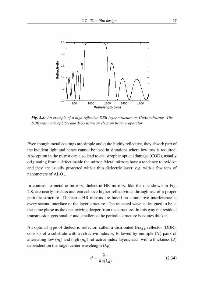
Fig. 2.8: An example of a high reflective DBR layer structure on GaAs substrate. TheDBR was made of SiO2 and TiO2 using an electron beam evaporator.
Even though metal coatings are simple and quite highly reflective, they absorb part ofthe incident light and hence cannot be used in situations where low loss is required.Absorption in the mirror can also lead to catastrophic optical damage (COD), usuallyoriginating from a defect inside the mirror. Metal mirrors have a tendency to oxidizeand they are usually protected with a thin dielectric layer, e.g. with a few tens ofnanometers of Al2O3.
In contrast to metallic mirrors, dielectric HR mirrors, like the one shown in Fig.2.8, are nearly lossless and can achieve higher reflectivities through use of a properperiodic structure. Dielectric HR mirrors are based on cumulative interference atevery second interface of the layer structure. The reflected wave is designed to be atthe same phase as the one arriving deeper from the structure. In this way the residualtransmission gets smaller and smaller as the periodic structure becomes thicker.
An optimal type of dielectric reflector, called a distributed Bragg reflector (DBR),consists of a substrate with a refractive index ns followed by multiple (N) pairs ofalternating low (nL) and high (nH) refractive index layers, each with a thickness (d)dependent on the target center wavelength (λB):
d =λB
4 n(λB). (2.34)

28 2. Optical thin films
λB is also called the Bragg wavelength. This structure can be written in transfermatrix form with eq. (2.6)–(2.11) and (2.14). We obtain the propagation matrix
Pl =(
eiφl 00 e−iφl
)=(
i 00 −i
)(2.35)
and the system matrix for a single quarter-wave layer is
DlPlD−1l =
(1 1nl −nl
)(i 00 −i
)12
(1 1
nl
1 − 1nl
)= i(
0 1nl
nl 0
). (2.36)
Thereby, the transfer matrix for the whole DBR structure is
M = D−10
[N
∏DHPHD−1H DLPLD−1
L
]Ds
=(−1)N
2
11n0
1 − 1n0
N
∏
01
nHnH 0
01nL
nL 0
( 1 1ns −ns
)
=12(−1)N
(
nL
nH
)N
+ns
n0
(nH
nL
)N (nL
nH
)N
− ns
n0
(nH
nL
)N
(nL
nH
)N
− ns
n0
(nH
nL
)N (nL
nH
)N
+ns
n0
(nH
nL
)N
. (2.37)
This can then be substituted into eq. (2.17) to get the DBR’s reflectivity at λB atnormal incidence:
R =∣∣∣∣M21
M11
∣∣∣∣2 =
∣∣∣∣∣∣∣∣∣ns
n0−(
nL
nH
)2N
ns
n0+(
nL
nH
)2N
∣∣∣∣∣∣∣∣∣2
. (2.38)
This result can also be found in other equivalent forms [102, 117]. Nonetheless, itis important to realize that a reflectivity of 1 can never be reached. Using typicaldielectric materials, mirrors that reflect at least 99.99984 % [104] have been reliablydemonstrated. The ultimate limiting factors for mirror reflectivity are scattering, ma-terial losses [118] and DBR stack adhesion (too thick layer structures are not stableenough). A typical reflectivity curve is presented in Fig. 2.8. This DBR was usedin [P2] in the bottom section of the Gires–Tournois interferometer (GTI). More de-tails of DBR manufacturing can be found from my Master’s thesis [119]. The usable

2.7. Thin film design 29
DBR width ∆λ, i.e. the high reflective region, increases with refractive index contrast,∆n = nH−nL, of the DBR layers. Typical dielectric materials for DBRs are TiO2(n =1.9–2.6, in this thesis about 2.15), Ti3O5, TiO, Al2O3(n = 1.59) and SiO2(n = 1.44–1.46). For the semiconductor mirrors covered in this thesis, AlAs (n ≈ 2.9 at 1.5µm) and GaAs (n = 3.5 at 1 µm) were typical compound semiconductor materials forDBRs. Semiconductors in this thesis were grown by molecular beam epitaxy (MBE).The advantage of MBE is that it offers the possibility to grow both lattice-matchedand strained crystal layers, which have varied refractive index. However, semicon-ductors have low losses only for certain wavelength regions above their bandgap andeven then, DBRs with lattice matched materials have relatively low ∆n. As a con-sequence, the high reflectivity bandwidth of a semiconductor DBR is narrow, and alarge number of pairs, on the order of 20–40, is typically needed to reach reflectivitiesover 99.9 %.
2.7.3 Dichroic coatings
Numerous applications require separation of different wavelengths of a light beam.Typical examples of such applications are sunglasses, video projectors and laser out-put couplers. In some cases only one wavelength range is needed and the other isredirected away. This task can be handled with a dichroic mirror. In this thesisdichroic coatings are used in laser cavities with closely separated wavelengths, mak-ing the coatings fairly challenging.
Wavelength separation is typically achieved by designing an interference edge filterwith a DBR structure that reflects one of the wavelengths well and modifying it suchthat it transmits the other wavelength or wavelength range. The high transmissionregion naturally requires us to suppress the DBR sidebands. This can be achievedby choosing a modified DBR-based starting structure and refining it to match therequired reflection and transmission targets.
Common edge filter starting structures [32] on top of a substrate are of the formH2 LHLH . . .L H
2 or L2 HLHL . . .H L
2 , where H stands for high refractive index quarterwave layer (see eq. (2.34)) and L for low index quarter wave layer, i.e. the structure isthe same as that of the DBR, but it starts and ends with the same material, and thoselayers are only half the thickness of a normal quarter wave layer. This starting pointalready reduces the sideband reflections and additional optimization based on thetargets further significantly improves the result. The starting structure can also havea phase-matching section to dampen the sidebands even more: for example addinga low refractive index layer (L) outside the H/2 layer dampens the sidebands for a

30 2. Optical thin films
0 1000 2000 3000 4000
1
2
3
Ref
ract
ive
inde
x
Distance from the top (nm)
1000 1200 1400 1600 1800 20000.0
0.2
0.4
0.6
0.8
1.0
Ref
lect
ivity
Wavelength (nm)
1
2
3
Ref
ract
ive
inde
x
Fig. 2.9: (top) An example of a SiO2/TiO2 long-wave pass filter (black). The target wasto reflect over 99 % in the 950–1100 nm wavelength range and transmit over 98 % inthe range 1200–2000 nm. The starting structure before layer optimization (green) anda normal DBR (blue) are also presented for comparison. Refractive index profiles of thestarting structure (middle) and the long-wave pass filter (bottom) reveal that the filterprofile remains highly periodic in the optimization i.e. it is only slightly modified fromthe starting point, but the figure of merit is improved by a factor of 2807.
long-wave pass edge filter. Such a starting structure is used in the example depictedin Fig. 2.9. Of course the number of layers in the structure is important and as a ruleof thumb we can say that the more layers we have, the sharper the transition from thehigh reflection to high transmission regions can be. Naturally, if we choose too high anumber of layers, the optimization becomes more complicated and we face adhesionand manufacturing problems with the result. In our example the targets were fairlywell matched, but the optimization with Matlab’s Nelder-Mead simplex algorithmtook already 5.3 hours.

2.7. Thin film design 31
2.7.4 Dispersive mirrors
Dispersive mirrors are a major part of this thesis and their advantages and disadvan-tages are discussed in more detail in publications [P1], [P2] and [P4] and in chapter 3.In the following subsections we describe the background and introduce the generalstructures of the basic dispersive mirrors. Fabry-Pérot etalons and Gires–Tournoisinterferometers are more relevant to this thesis but double-chirped mirrors are alsodiscussed due to their great significance for low-dispersion compensation in ultrabroad band femtosecond solid-state lasers. However, chirped mirrors are not suitablefor fiber laser dispersion compensation because of their very small dispersion.
Fabry–Pérot etalons
The Fabry–Pérot (FP) etalon is a form of multiple-beam interferometer [35], wherethe interference occurs not in separate interferometer branches like in a Mach-Zehndertwo-beam device, but instead inside a resonant structure with two high-quality paral-lel mirrors, usually DBRs, spaced by a lossless cavity, typically made of fused silicaor evaporated SiO2. The term FP interferometer and etalon are often used inter-changeably, but here we attempt to emphasize that ”etalon” refers to a single, soliddevice, whereas ”interferometer” is more general classification and can include de-vices and setups which have e.g. an air cavity. FP etalons are particularly importantfor optics since they are used in filters to pick narrow spectral lines. However, a sin-gle FP cavity results in a triangle-shaped transmission spectrum and the shape can bemade more rectangular by combining two or more etalons spaced by a coupling layerin between.
The full transmission at the resonant wavelengths occurs when the parallel mirrorshave equal reflectivities (perfect mode matching is assumed). FP etalon properties fordifferent mirror reflectivities are depicted in Fig. 2.10. This shows that the higher thereflectivities (R) are, the sharper the resonance lines are, i.e. the finesse is higher. Dis-persive properties are discussed in section 3.5. Finesse is defined as ”the free spectralrange divided by the full width at half maximum (FWHM) width of resonances of anoptical resonator.” [120] The FP etalon finesse is given by
F =π(R1 R2)1/4
1− (R1 R2)1/2 , (2.39)
where R1 and R2 are mirror reflectivities. In an ideal etalon the mirror reflectivities

32 2. Optical thin films
900 950 1000 1050 11000.0
0.2
0.4
0.6
0.8
1.0
Ref
lect
ivity
Wavelength (nm)
0 1000 2000 3000 4000 5000 6000 70001.0
1.4
1.8
2.2
Ref
ract
ive
inde
x
Distance from the top (nm)Fig. 2.10: (top) Examples of reflectivity spectra from Fabry–Pérot etalons consisting ofa 4137.9 nm SiO2 cavity between dielectric DBRs with different numbers of pairs. TheDBRs with 1000 nm Bragg wavelength have half a pair (orange, R = 0.273), 1.5 pairs(black, R = 0.563), 2.5 pairs (blue, R = 0.771) 3.5 pairs (purple, R = 0.889) and 4.5pairs (green, R = 0.948). (bottom) The FP etalon with 4.5 pairs at each side of thecavity has a finesse of about 58.5 and its refractive index profile is shown in the lowergraph.
are identical, R, but this is seldom the case. Equal mirror reflectivities result in asimplified finesse formula
F =π√
R1−R
. (2.40)
However, the etalon finesse can degrade with roughness of the optical surfaces of themirrors [121]. The surface quality is measured as the roughness, ∆xsur f ace, which isthe deviation from the planarity and is compared to the wavelength of the light, λlight :
∆xsur f ace =1m
λlight . (2.41)
The deviator m in the equation is typically in the range 2–100 and relates to theroughness finesse as

2.7. Thin film design 33
Froughness =m2
, (2.42)
and thus the total finesse Ftotal is given by
1Ftotal
=1F
+1
Froughness. (2.43)
Gires–Tournois interferometers
A Gires–Tournois interferometer (GTI) is a resonant structure consisting of two par-allel mirrors spaced by a low loss cavity. Therefore it is similar to a FP etalon but thetop mirror should be only partially reflective, while the bottom mirror should reflectas much as possible to avoid losses. Hence, we can call a GTI an asymmetric FPetalon. The basic structure is presented in Fig. 2.11.
Substrate
Top DBR
Cavity
Bottom DBR
Fig. 2.11: Basic GTI structure for dispersion compensation.
If the cavity is lossless and the bottom mirror has several orders of magnitude less re-flection losses than the top mirror, the GTI reflectivity stays high for all wavelengths,but the phase of the reflected light is strongly frequency-dependent due to the reso-nance effect. This causes group delay dispersion (GDD). However, in practice thebottom mirror always leaks a certain amount of light to the substrate which results inan effective cavity loss. The effect is especially pronounced near the resonance wave-length where the light propagates multiple round-trips and this appears as a resonancedip in the reflectivity spectrum. An example is shown in Fig. 2.12.
The original design was first introduced by Francois Gires and Pierre Tournois in1964 [122]. They suggested that the structure provides a large group delay at res-onance frequencies, which depend on the cavity optical thickness. Later, the GTI

34 2. Optical thin films
800 900 1000 1100 1200 13000.0
0.2
0.4
0.6
0.8
1.0
Ref
lect
ivity
Wavelength (nm)
Resonance
Fig. 2.12: An example of a dielectric GTI with visible losses at the resonance wavelengthof 1032.8 nm. However, the dispersion is zero at the resonance, where the losses arehighest, and the short pulse laser should be operated slightly below the resonance, wherelosses are smaller.
group delay was used to introduce a small group delay dispersion for a dielectric mir-ror [123] and a few years later, a GTI design was used to generate 44-fs and soon afteralready 14-fs pulses [124, 125]. However, these lasers were solid state lasers with ashort crystal and required only a very small amount of dispersion compensation to op-erate. Moreover, these lasers were pumped with bulky gas lasers, making them lesspractical than modern fiber lasers. Afterwards multi-cavity thin film GTIs were intro-duced as an alternative approach to realize anomalous dispersion mirrors [126, 127],but these mirrors could generate only little dispersion and they could not be used forfiber laser dispersion compensation.
Large dispersion values can be achieved near the GTI cavity resonance, but the op-eration bandwidth becomes narrower as the mirror finesse increases and the effectof higher order dispersion can not be neglected. Typical dielectric GTI reflectivity,group delay and dispersion values are presented in Fig. 2.13. The design’s dispersiveproperties are discussed further in section 3.4.
Double-chirped mirrors
Double-chirped mirrors (DCM) appeared in the 1990s to meet the need to compen-sate for the gain crystal dispersion of solid state lasers in a broad wavelength range.Compared to earlier dispersion compensation techniques, they enabled remarkable

2.7. Thin film design 35
1020 1023 1026 1029 10320.93
0.94
0.95
0.96
0.97
0.98
0.99
1.00
0
200
400
600
800
1000
Ref
lect
ivity
Wavelength (nm)
Resonance wavelength
Gro
up d
elay
(fs)
(a)
1020 1023 1026 1029 1032-0.25
-0.20
-0.15
-0.10
-0.05
0.00
0.05
0.10
0.15
0.20
0.25
-30
-25
-20
-15
-10
-5
0
5
10
GD
D (p
s2 )
Wavelength (nm)
TOD
(107 x
fs3 )
(b)
Fig. 2.13: (a) A typical GTI reflectivity (black) spectrum around the resonance wave-length with corresponding group delay (green). (b) The GTI’s group delay dispersion(solid line) and third order dispersion (dashed line).
Substrate
Quarter-wave section
Simple-chirp section
Double-chirp section
AR
coating
Matching to air
Fig. 2.14: Example of double-chirped mirror sections. All the sections are merged in theend result, and sections other than the DCM section are not necessarily required. How-ever, including them in the initial structure gives a good starting point for subsequentdesign optimization.
improvements in the field of generating ultra-short pulses [128, 129]. The requiredreflectivity needs to be high over a wide spectral range because these lasers, e.g. Ti-sapphire, do not tolerate high cavity losses [130]. This can be achieved with a DBR-like structure with some modifications concerning the phase shift and consequentlymirror dispersion. Naturally, mirrors need to be dielectric due to material dispersionand loss issues, but the structures nevertheless become very thick. A common DCM(see Fig. 2.14) consists of a DBR on a substrate followed by a chirped DBR (CDBR)section.
The chirping means that the center wavelength for the DBR stopband progressivelydecreases or increases, depending on the target dispersion sign, as the layer number( j) increases (1 being the first layer from the top). The CDBR can be followed orreplaced by a double-chirp section [131, 132] if compensation of the higher orderdispersions is required [133] or if the dispersion profile for the second order disper-

36 2. Optical thin films
sion needs to be of a certain shape e.g. particularly flat. The entire structure shouldfinally be matched to air or another intermediate medium with an anti-reflection coat-ing to ensure optimal DCM behavior. An unmatched structure will have unwantedroughness in the dispersion characteristics. These problems can also be reduced byoperating the mirror from the substrate side and making the anti-reflection coating atthe rear side of the component [134].
A DCM with a large GDD, on the order of several hundreds of fs2, cannot be flatover a broad spectral range. Mirrors with GDD values on the order of ±1000 fs2 arecommercially available in a limited range, but large bandwidths of several hundredsof nanometers typically have a dispersion of about 50±50 fs2. Such mirrors are oftenused in pairs, where the GDD oscillations cancel out each other to give an overallflat dispersion profile. The DCM’s limited dispersion is often enhanced by placingseveral, or even a dozen, DCMs into the laser cavity, making the technique complexand expensive.
Double-chirped mirror design strategy
The DCM mirrors are typically very time-consuming and challenging to design buta reasonable result can be achieved with, for example, the following design strategy.First we need to define parameters to vary the local Bragg wavelength (λB) and dutycycle (r) as follows:
λB( j) = b0 +b1 j +b2 j2 +b3 j3, (2.44)
where j is the number of the layer ( j = 1 for the layer at the air interface), b0−3 areoptimization coefficients and
r( j) =1+ tanh
(j−PD
)4
, (2.45)
where P and D are optimization coefficients for the duty cycle. Next we need todefine a figure of merit (FOM), which accounts for deviations from the target disper-sion level as well as reflection losses. An ideal design would have FOM = 0. In thedesign program a preliminary Monte-Carlo optimization is done for the 6 parametersP,D and b0−3 within predefined upper and lower limits. The last step is the full op-timization of all layers to utilize the full potential of the layer structure and smooththe dispersion characteristics. Usually this algorithm needs to be repeated multiple

2.8. Summary 37
times in order for the designer to learn proper starting parameters and their bound-aries for the refractive index pair in use. As a rule, the higher the relative refractiveindex change for the used materials is, the broader the wavelength range that can beachieved.
2.8 Summary
In this thesis work we have studied the available material selection for optical thinfilms and chosen the optimal materials for each purpose. Our thin film design isbased on mature design practises which we have developed further in this work toaid ultrafast fiber laser development. The most important thin film structures in thisthesis are Gires–Tournois interferometers, Fabry–Pérot etalons, dichroic mirrors andanti-reflection coatings.

38 2. Optical thin films

3. YTTERBIUM MODE-LOCKED FIBER LASERS
This chapter gives a short overview of ytterbium fiber laser mode locking and themain components for mode-locked fiber lasers. We then discuss the work done in thisthesis to improve Yb-fiber laser performance using alternative, advanced solutions.The main emphasis is on fiber laser dispersion compensation, showing new optionsto be reckoned with for anyone wanting to design a simple short pulse fiber laser.The main advances deal with compensating for cavity fiber dispersion with electronbeam evaporated dielectric thin film structures.
3.1 Mode locking
Though short pulses can be achieved with the Q-switching technique [135], the short-est laser pulses can be generated exclusively via mode locking (ML). It is based onmultiple modes exited in the laser cavity with coupled phases. This sets a number ofrequirements for the laser dynamics and dispersion properties in order for the modelocking to be started and sustained. Self-starting requires that the laser cavity favorsshort pulses over cw light. After that the mode-locked pulse evolves for some hun-dreds to a few thousand round trips [136] until it reaches the steady-state. However,the pulse duration doesn’t evolve to the ultrashort regime unless the dispersion andpulse shaping mechanisms are properly adjusted. The small anomalous dispersionrequired for soliton formation usually enables even shorter pulses by balancing thecavity GDD and the nonlinear refractive index change from self-phase modulation(SPM).
3.1.1 Active mode locking
Fiber lasers can be mode-locked either actively or passively [137]. Active ML, wherea modulator introduces amplitude or phase modulation to the laser cavity, requires anexternal signal to sustain the mode locking. The modulation frequency, ωm, needs

40 3. Ytterbium mode-locked fiber lasers
to be matched closely to the laser’s mode separation frequency ∆ωe [138], which isdetermined by the cavity round trip time, TR, as
∆ωe = 2π1TR
. (3.1)
This modulation causes the laser axial mode with frequency ωe to form sidebands atfrequencies ωe± n ·ωm. These sidebands then enable the axial modes to lock theirphases together. As a result of this mode coupling, the multiple spectral componentsform a Gaussian pulse [139]
E(t) = E0 exp(−t2/τ
2), (3.2)
where the τ is proportional to the pulse duration and is given by
τ = 4
√8g
mωm ωg, (3.3)
where m is the modulation depth, ωm is the modulation frequency and ωg is the gainbandwidth. However, it is important to note here that the pulse width is not limitedmerely by the gain bandwidth and modulation but also by the dispersion.
3.1.2 Passive mode locking
Ever since the first picosecond pulses were generated with only the help of a pas-sive, saturable absorber element, e.g. semiconductor, [140, 141], passive mode lock-ing has been the means for generating the shortest pulses [139]. Nonlinear opticalmethods for passive mode locking [137, 139] include use of fast or slow saturableabsorbers, additive pulse mode locking (APM), polarization APM, Kerr-Lens modelocking (KLM) and nonlinear amplifying loop mirrors (NALM) as artificial saturableabsorbers.
When dealing with fiber lasers, we need to remember that they are also susceptibleto Q-switching and Q-switched mode locking (QSML) due to their long upper-statelifetimes. This can be avoided by using a saturable absorber with low modulationdepth even though this makes laser self-starting more difficult [138].
As with active mode locking, a broad spectrum is needed to support short pulses. Inan ideal case, i.e. the best pulse quality, the relationship between the pulse width ∆τp
and the spectral width ∆ωs is governed by the Fourier transform limitation, which

3.2. Ytterbium fiber lasers 41
tells us that for a Gaussian pulse the time-bandwidth product [142] is
∆τp ∆ωs ≥ 0.441. (3.4)
This product for a hyperbolic secant (sech) pulse shape is about 0.315. This meansthat, for example, the shortest pulse durations that can be generated at 1030 nm witha spectral bandwidth of 2 nm are 727 fs for Gaussian pulses or 557 fs for sech pulses.
3.2 Ytterbium fiber lasers
Ytterbium (Yb) is a rare-earth element that is nowadays a common optical fiberdopant. Ytterbium fiber can provide a broad-gain bandwidth with excellent powerconversion efficiency, enabling high output power from a laser or amplifier [143]. Ybcan also be inserted at high doping levels with e.g. the direct nanoparticle deposition(DND) process [144], leading to high gain in a short length of fiber [P2]. The broadgain bandwidth is required for ultrashort pulse amplification while the high saturationfluence allows for high pulse energies. The ytterbium absorption and emission crosssection and energy level diagram are presented in Fig. 3.1. Ytterbium’s remarkablegain bandwidth is also demonstrated in [P1], where Yb provides gain for picosecondpulses in the whole range from 980 nm up to 1105 nm.
940
nm
2F5/ 2
2F7/ 2
100008000600040002000
12000
Ene
rgy
(cm
-1)
800 120011001000900Wavelength (nm)
Emission
Absorption
Cro
ss s
ectio
n (x
10-2
4m
2 ) 3
1
2
0
976
nm
1080
nm
990
nm
0
Fig. 3.1: (left) Ytterbium-doped fiber absorption and emission cross section and (right)energy level diagram [145].
As a result of ytterbium’s high conversion efficiency and good thermal dissipationtechniques, Yb-fiber lasers with amazing power levels have been demonstrated inboth cw and ultrafast regimes [70, 72]. The efficient heat dissipation of the fiberowing to its large surface to active volume ratio and the superb beam quality of the

42 3. Ytterbium mode-locked fiber lasers
guided mode determined only by the fiber core characteristics are the well-knownadvantages of single-mode fibers. High power is also supported by the long interac-tion length. This is especially helpful when using double-clad fiber since the pumplight is launched into the outer cladding and is gradually absorbed to the inner coreover the entire fiber length. However, the long interaction length also brings prob-lems to ultrafast lasers with fiber nonlinearities like SPM, which originates from thethird-order susceptibility χ(3), and is responsible for the intensity-dependent refrac-tive index in the form of n = n0 +n2 I. Another fiber nonlinearity issue is stimulatedinelastic scattering [146], where the light transfers a part of its energy to the glasshost material in the form of excited vibrational modes. A frequency shift of about13 THz is observed with the excitation of optical phonons. This process is calledstimulated Raman scattering (SRS). A smaller shift occurs with stimulated Brillouinscattering (SBS) when an acoustical phonon is excited and the shift is on the orderof 17 GHz. Both SRS and SBS could provide a notable power loss mechanism inhigh intensity fiber lasers but when dealing with ultrashort pulses in fibers, the largespectral width is much broader than the Brillouin gain bandwidth and the effect ofSBS is negligible.
Ytterbium fiber lasers have various applications ranging from laser welding [147]and supercontinuum generation [148–150] to more sophisticated applications likecoherent anti-Stokes Raman scattering (CARS) microspectroscopy [151].
3.2.1 Saturable absorbers
The upper-state lifetimes of rare-earth-doped fibers are long (ms level), implying thatthe gain does not recover within the cavity round-trip time, which is typically below1 µs. Therefore, a fast nonlinear device is needed to clean up both the leading andtrailing edges of the pulse and a fast saturable absorber is one solution.
Saturable absorbers are divided in two categories depending on their recovery time,fast and slow. Semiconductor, carbon nanotube and dye have been used in ultra-fast lasers, but this thesis concentrates on semiconductor saturable absorber mirrors(SESAMs) for mode locking. The absorbers used in this study are described in manypublications and a more complete overview of SESAM design and their parameterscan be found from [138, 152].
There are four important parameters for SESAMs. They are
• recovery time (τA),

3.2. Ytterbium fiber lasers 43
• saturation fluence (Fsat,A), which is the saturation energy (Esat,A) per unit areathat reduces the initial low-intensity reflectivity to 1/e (∼37 %) of its initialvalue, a typical unit is µJ/cm2,• modulation depth (q0), also known as saturable (bleachable) losses and• non-saturable losses (qnonsat), preferably as small as possible.
In addition to these parameters, properties like damage threshold and two-photonabsorption (TPA) and the resulting roll-over (additional losses) can be importantwith ultrafast lasers. Typical SESAM behavior with increasing fluence is shown inFig. 3.2.
0.1 1 10 1000
2
4
6
8
10
12
Ref
lect
ivity
Cha
nge
(%)
Fluence (μJ/cm2)
Fsat,A=3.0 μJ/cm2
Fig. 3.2: Nonlinear reflectivity of a GaInNAs-based SESAM [P1]
3.2.2 Fiber components
Fiber lasers consist of different fiber components, and most of them contribute tothe cavity dispersion. Typical components are fiber couplers, like output couplersand wavelength division multiplexers (WDMs), fiber isolators, fiber pigtailed pumpdiodes and gain fiber. All these components are based on commercial mature tech-nology and are readily available.
Whereas laser mirrors have individual GDDs per reflection, for fiber the dispersionaccumulates throughout the whole fiber. Moreover, the dispersion for fibers is a sumof material and waveguide dispersion and thus it is convenient to account for these

44 3. Ytterbium mode-locked fiber lasers
together using a mode-propagation constant [146], β, and expand it mathematicallyin a Taylor series about the spectrum center frequency, ω0, as
β(ω) = n(ω)ω
c= β0 +β1 (ω−ω0)+
12
β2 (ω−ω0)2 +16
β3 (ω−ω0)3 + · · · , (3.5)
where
βm =(
dmβ
dωm
)ω=ω0
(m = 0,1,2, . . .). (3.6)
The β2 represents dispersion of the group velocity and is the main mechanism re-sponsible for pulse broadening in fiber. The phenomenon is known as group velocitydispersion (GVD) and β2 is the GVD parameter. However, in fiber optics literature,dispersion is often given by the dispersion parameter, D, which is related to β2 by therelation
D =−2πcλ2 β2. (3.7)
D is usually given per unit length in units ps/nm/km and for standard fiber it is zeroaround 1.31 µm. This wavelength is called the zero-dispersion wavelength, λD. NearλD third order dispersion (TOD) becomes dominant.
3.3 Dispersion compensation techniques for the 1 µm region
The fiber’s normal dispersion is one of the major obstacles for ultrafast pulse gen-eration in ytterbium fiber lasers even though mode locking with short pulses is alsopossible in positive net-cavity dispersion fiber lasers [153].
If a light pulse is propagated through a medium with normal dispersion, the resultis that higher frequency components (blue) travel slower than lower frequency (red)components. The pulse therefore becomes chirped. Conversely, if a pulse travelsthrough an anomalously dispersive medium, high frequency components travel fasterthan lower frequency ones. The result of GVD, whether negative or positive, is ulti-mately temporal spreading of the pulse.
However, there are various ways to compensate for the cavity dispersion and this the-sis provides a few new ways to do it. A common dispersion compensation methoduses a diffraction grating pair, where the pulse is spread spatially and different fre-quencies propagate for different distances. The basic concept of a diffraction grating

3.3. Dispersion compensation techniques for the 1 µm region 45
pair is shows in Fig. 3.3. Positive features include high damage threshold and largeattainable dispersion. However, such a system easily has 25 % losses even with goodalignment and it is somewhat bulky due to the required free space components. Inaddition to the gratings, the light has to be collimated from the fiber to the gratingswith an extra lens and reflected back with a mirror. Gratings can also be positionedin a more complicated non-parallel configuration with two lenses to achieve normaldispersion for e.g. pulse stretching.
λ
Fig. 3.3: Grating pair configuration for anomalous dispersion i.e. the shorter wave-lengths (in blue) travel a shorter path than the longer wavelengths (in red). The arrowpoints in the direction of increasing wavelength.
Another common method for dispersion compensation is a prism pair, or four prismsto restore the original shape of the collimated beam. The prism sequence, shown inFig. 3.4, is a classical solution for creating negative or positive dispersion in a lasercavity [154,155]. Prisms are generally used at the minimum deviation angle, i.e. withthe incident angle equal to the exiting angle. The apex angle, φ, should be cut in sucha way that the rays enter and leave each prism at Brewster’s angle. This minimizesreflection losses from the prism surfaces. Anomalous dispersion at 1 µm occurs whenthe angular dispersion, which is anomalous, overcomes the prism’s normal materialdispersion. This requires the prism separation, L, to be large enough, making the con-
Lλ
φ
φ
Fig. 3.4: A prism pair inducing negative (anomalous) group delay dispersion.

46 3. Ytterbium mode-locked fiber lasers
figuration space-consuming. Moreover, a prism pair configuration is difficult to alignand doesn’t produce high dispersion values at reasonable prism separations. This iswhy prism pair use with fiber lasers is typically limited to compensation of higherorder terms with e.g. grating pairs. Detailed calculations of dispersive properties canbe found for example in [155, 156].
In addition to grating pairs and prisms, there are also various other methods for dis-persion compensation at the Yb-gain region; these include GTI’s and FP etalons,which are discussed in this thesis, various semiconductor structures like dispersion-compensating saturable absorber mirrors (D-SAM), resonant saturable absorber mir-rors (RSAM) and dispersive fibers like photonic band gap fibers (PBGF) [157, 158](see Fig. 3.5), which are a form of photonic crystal fiber (PCF), fiber tapers andchirped fiber Bragg gratings (CFBGs). Typical properties of these components aresummarized in Table 3.1. In this table we are particularly interested in the bandwidth-GDD-product (∆ωGDD [THz] x β2 [fs2]), which gives a good figure of merit for themethod. We also compare the third order dispersion (TOD) to the reveal methods’suitability to ultrashort pulse generation. From the table we can conclude that no sin-gle method is suitable for every application but when it comes to fiber lasers, DCMs,chirped mirrors, prism, D-SAMs and RSAMs are of little use around 1 µm due totheir small dispersion. The CFBGs are also difficult to use because of their largedispersion, and they have mainly been used in CPA applications. However, quite re-cently, state-of-the-art CFBG with lower dispersion, on the order of 0.1 ps/nm, havebeen demonstrated with tens of nm bandwidth, and the laser could produce ps-pulsesand down to 218 fs pulses with external compression [159].
(a) (b) (c)
Fig. 3.5: A Few examples of photonic bandgap fiber cross-sections: (a) hollow core[160], (b) high nonlinearity [161] and (c) dispersion compensating [162].

3.4. GTI dispersion compensation 47
Table 3.1: Comparison between different dispersion compensation methods. Band-widths for GDD are FWHM unless the device transmission or reflectivity sets a morestrict limitation for laser operation. GDDs are average values over the usable band.
Bandwidth GDD Bandwidth x TODMethod (nm) / (THz) (fs2) GDD (THz x fs2) (fs3) References
GTI 1.8 / 0.51 −1.44 ·105 −7.4 ·104 ∼ 5 ·107♦ [P2]GTIP 3.5 / 1.0 −1.53 ·105 −1.5 ·105 ±3 ·107♦ Fig. 3.10FP etalon] 3.56 / 0.98∗ −2.0 ·104 −1.95 ·104 −6 ·106 [P4]DCM 370 / 49 –100 −4.9 ·103 very low [163]DCM pair? 600 / 250 ∼ –50 −1.2 ·104 very low [164]Chirped mirror 300 / 128 –50 −6.4 ·103 +75 [129]Grating pair� ∼ 80 / 22 −8.2 ·104 −1.8 ·106 +1.8 ·105† [165]Prism pair‡ 500 / 180 –640 −1.1 ·105 +1380 [155]PBGF 22 / 6.1 −5 ·104 −3.1 ·105 1.4 ·106 [162]Fiber taper• 100 / 27.3 −2.87 ·104 −7.8 ·105 3 ·104 [166]CFBR 27 / 7.4 −2.58 ·106z −1.9 ·107 high [149]D-SAM 15 / 6.3 −400 −2.5 ·103 low [167]RSAM 7 / 1.9 –3150 −5.8 ·103 2.0 ·105 [168]
Remarks♦ A typical value, TOD varies considerably in the usable range as seen in Fig. 3.11] Values are for one round trip∗ Bandwidth is limited by the transmission? Two-mirror system, bandwidth x GDD per mirror is −6.2 ·103 THz fs2
� Double pass, 1200 lines/mm, separation 1 cm, β=55◦, bandwidth is a rough estimate† The ratio of TOD and GDD increases with lines/mm, e.g. typical β3/β2 =−4 fs for
1200 lines/mm and β3/β2 =−15 fs for 1750 lines/mm‡ Double pass, L = 50 cm• Taper waist diameter about 1.8 µm, waist length 20 cm, TOD estimated in [169]z Far too great for Yb-fiber laser cavity compensation, used mainly in CPA configurations
3.4 GTI dispersion compensation
One of the major results of this thesis is the demonstration that a properly designedGTI can compensate for the Yb-doped fiber laser cavity dispersion [P1–P2]. This ispossible due to the large anomalous dispersion in a GTI below the resonance wave-length (see Fig. 3.6). However, the large dispersion can be generated only over arelatively narrow bandwidth. The autocorrelation reveals that the spectrum is suffi-cient to support at least 1.5 ps pulses which are shown in Fig. 3.7. A certain error inthe pulse width measurement is always present with autocorrelation due to the factthat the pulse shape is assumed. We used a Gaussian pulse shape in our fit and be-lieve that it best resembled our situation. At the time, we were not able to performdispersion measurements for our GTI in [P2] but later it was fully characterized us-ing a phase-locked interferometer dispersion measurement system. As a result, the

48 3. Ytterbium mode-locked fiber lasers
calculated GDD values proved to be accurate within a few percent compared to themeasured values, which is evident from the group delay results presented in Fig. 3.8.
1016 1018 1020 1022 1024 1026 1028 1030 10320.0
0.2
0.4
0.6
0.8
1.0
0.90
0.92
0.94
0.96
0.98
1.00
-0.20-0.15-0.10-0.050.000.050.100.150.20
Pulse spectrum with HR mirror Pulse spectrum with GTI
Inte
nsity
(arb
. uni
ts)
Wavelength (nm)
Ref
lect
ivity
GD
D (p
s2 )
Fig. 3.6: (top) The measured reflectivity and calculated GTI group delay dispersion in[P2]. (bottom) Laser spectra with and without GTI dispersion compensation.
-40 -30 -20 -10 0 10 20 30 400.0
0.2
0.4
0.6
0.8
1.0
Gires Tournois structure τpulse= 1.5 ps
Nor
mal
ized
Am
plitu
de
Time (ps)
High reflective mirror τpulse= 15.6 ps
Fig. 3.7: The autocorrelation trace in our Yb-doped fiber laser using a normal highreflective mirror and a GTI. The pulse widths were obtained from the Gaussian fits ofautocorrelation with a conversion factor that is a function of the assumed pulse shape.For a Gaussian pulse the factor is 0.707. We can see that the pulse width is shortenedto a tenth of the original using a GTI structure.

3.4. GTI dispersion compensation 49
1020 1030 1040 1050 1060
0
100
200
300
400
500
Measured GD (fs) Calculated GD (fs)
Gro
up d
elay
(fs)
Wavelength (nm)
structure:3.5 pairs of TiO2/SiO2+1xλ cavity + 10 pairs of of TiO2/SiO2
on GaAs
Fig. 3.8: The measured GTI group delay and the calculated target shows remarkablygood correlation. The measured sample is similar to the one shown in [P2] but with onepair less in the top DBR section.
The GTI’s FWHM bandwidth times its maximum dispersion is fairly constant but wecan increase it by using a GTI prism (GTIP) which was invented during this thesiswork and is to the best of my knowledge, the first time that this idea is presented. Theprism is a cut and polished piece of glass or other transparent material with parallel,polished ends at a selected angle with respect to the sides. This structure is shown inFig. 3.9. The sides of this structure are coated with a reduced finesse GTI and a highreflective mirror providing a multiple-bounce setup. The makes the usable bandwidthlarger and reduces the amount of dispersion per reflection.
HR surface
GTI surface
Fig. 3.9: GTI prism structure and beam propagation with three reflections from the GTIsurface i.e. a total of six reflections per laser cavity round trip.
Since the bottom mirrors are evaporated last, we can evaporate a large number ofDBR pairs to minimize losses and even finish the structure with a metallic material to

50 3. Ytterbium mode-locked fiber lasers
minimize optical leakage. The light propagates in the prism and experiences multiple(N) reflections from the GTI surface which increase the dispersion by a factor of N.The advantageous effect is that a broader dispersion compensation bandwidth withlower losses can be achieved. It is also worth noting that the reflection losses aredistributed more evenly throughout the usable bandwidth. An example of this effectis shown in Fig. 3.10. Naturally, the finesse of the GTI cannot be reduced too muchsince each GTI bounce needs to compensate for the dispersion of the GTIP glasssubstrate. The alternative would be to build the GTIP as a free space componentconsisting of a parallel high reflective mirror and a GTI. This way the number ofbounces and the GTIP aperture could be varied more easily even though the idea ofa compact, integrated component would be lost.
1020 1023 1026 1029 10320.94
0.95
0.96
0.97
0.98
0.99
1.00
-0.25
-0.20
-0.15
-0.10
-0.05
0.00
0.05
0.10
0.15
0.20
0.25
GTI
GTIP
Ref
lect
ivity
Wavelength (nm)
GTIP
GTI
GD
D (f
s2 )
Fig. 3.10: Reflectivity (dashed line) and group delay dispersion (solid line) comparisonbetween a single reflection from a conventional GTI and 4 reflections inside a GTIP.The GTIP has 3.5 and the GTI 4.5 pairs in the top DBR, respectively, yielding roughlythe same losses and dispersion but broader usable bandwidth for GTIP. The usablebandwidth is marked with bidirectional arrows.
The GTIP also has other advantages over a conventional GTI: due to the GTIP’s lowerfinesse in the GTI structure, the TOD is essentially smaller, as can be seen in Fig.3.11. The GTI also sets a fixed wavelength for dispersion compensation when usedat normal incidence reflection mode. That wavelength depends on the evaporatedcavity thickness. Now, since the GTI surface in the GTIP is designed to operate atan angle, the resonance wavelength depends on the angle and the component can betuned continuously over several tens of nm by rotating it about its center. At thesame time, the laser cavity stays aligned since the GTIP ends are parallel and theGTIP geometry does not change the beam direction but merely shifts it spatially by

3.5. Fabry–Pérot etalons for dispersion compensation 51
a small amount. The tuning is limited by the laser beam diameter and the GTIPaperture. Since the reflectivity of a DBR mirror is angle-dependent, the GTI finessechanges slightly over the tuning range, and eventually the losses grow faster as theangle deviates significantly from the designed angle of operation. Still, I believe thatthe tuning range can easily be tens of nanometers in the ytterbium gain bandwidth.
1020 1023 1026 1029 1032-30
-25
-20
-15
-10
-5
0
5
10
TOD
(107 x
fs3 )
Wavelength (nm)
GTIP
GTI
Fig. 3.11: An example of the GTIP’s and the GTI’s third order dispersion. Both exhibita large TOD but the GTIP’s is still notably less.
3.5 Fabry–Pérot etalons for dispersion compensation
Fabry–Pérot etalons have conventionally been used as spectral filters in many op-tical and laser applications. However, these have relied on high finesse FP etalonsor interferometers and typically assumed that only the high transmission peaks ofetalons are relevant to the system. Now, it has been shown in publications [P4] and[S3] that with low finesse FP etalons, the fiber laser tends to operate in the anoma-lous dispersion range of the etalon resulting in pulse shortening. Unlike that of anasymmetric GTI, the FP etalon’s dispersion at wavelengths shorter than the resonancewavelength is normal in reflection but anomalous for transmission. The change in thesign of the dispersion occurs at a ”critical point” when the top (Rtop) and the bottom(Rbottom) mirror reflectivities change from roughly equal (Rtop ≈ Rbottom) to a situa-tion where the bottom mirror has notably higher reflectivity than the top mirror, i.e.Rtop� Rbottom. Also, if the cavity has losses (or gain) like in a semiconductor GTIdevice [170, 171], the critical point can change significantly.

52 3. Ytterbium mode-locked fiber lasers
Fig. 3.12 presents the FP etalon transmission with the corresponding mode-lockedpulse spectrum and we can clearly see that the laser operates in the anomalous dis-persion regime of the etalon. This is evident from Fig. 3.13 which shows a set ofround-trip transmission curves as the etalon is tuned. The figure also shows the mea-sured round-trip dispersions in transmission mode which are different from the dis-persion characteristics observed in the reflection.
1034 1036 1038 1040 1042 1044 1046 1048 1050 1052-70
-60
-50
-40
-30
-20
-36
-30
-24
-18
-12
-6
0
Mod
e-lo
cked
spe
ctra
l int
ensi
ty (d
Bm
)
Wavelength (nm)
Rou
nd tr
ip tr
ansm
issi
on (d
B)
Fig. 3.12: Fabry–Pérot etalon configuration’s round trip transmission in a laser cavitywith the resulting mode-locked spectrum.
1035 1040 1045 1050 1055 1060 1065-12
-9
-6
-3
0
-0.03
-0.02
-0.01
0.00
0.01
0.02
0.03
Tran
smis
sion
(dB
)
Wavelength (nm)
GD
D (p
s2 )
Fig. 3.13: Example of Fabry–Pérot etalon tunability and transmission GDD measure-ments.
The benefits of using a FP etalon in the laser cavity include easy, continuous tunabil-

3.6. Summary 53
ity and solitonic sideband suppression, shown in Fig. 3.14. The reason the sidebandsshould be suppressed is that in certain cases the spectral sidebands contribute to pulsebroadening [137], and naturally in some applications the sidebands would cause in-accuracy to the system wavelength.
1040 1045 1050 1055 1060
Inte
nsity
(10d
B/d
iv.)
Wavelength (nm)
(a) Without etalon
1030 1035 1040 1045 1050
Inte
nsity
(10d
B/d
iv.)
Wavelength (nm)
(b) With etalon
Fig. 3.14: When a laser operates in the soliton regime, the cavity anomalous dispersionleads to the formation of solitonic sidebands visible in (a). The FP etalon helps to filterout these spectral impurities. The laser in the situation in (b) is the same as in (a) exceptfor the etalon placed in the cavity to enable tuning and additional dispersion.
3.6 Summary
Use of a Gires–Tournois interferometer dispersion compensator and a short lengthof highly doped ytterbium fiber providing net anomalous group-velocity dispersionallowed us to realize a compact fiber laser. By incorporation of a novel semiconductorsaturable absorber mirror based on a GaInNAs structure, self-starting 1.5-ps-pulsemode-locked operation was obtained at 1023 nm with a repetition rate of 95 MHz. Inaddition, this chapter presents a novel GTI configuration where a GTI is integrated toa glass prism enabling wavelength tunability and improved dispersion characteristics.
This thesis also describes a dielectric thin film Fabry–Pérot etalon operated as adispersion compensator in a mode-locked fiber laser cavity. The etalon generatesanomalous dispersion near the low-loss spectral window and, consequently, the lasermode-locked by the semiconductor saturable absorber favors operation in the anoma-lous dispersion regime without a spectral filter. The etalon compensator is tunable,compact, easy to align, and suitable for picosecond and subpicosecond pulsed opera-tion.

54 3. Ytterbium mode-locked fiber lasers

4. FIBER LASER DYNAMICS AND RELAXATION OSCILLATIONS
This chapter discusses fiber laser dynamics and provides insight into two gain ma-terials, namely ytterbium (Yb) and thulium-holmium (Tm-Ho). We concentrate ondiscussing material properties with respect to laser energy levels and laser relaxationoscillations. The motivation for this comes from the laser tunability and startingmechanisms. When we tune the operation wavelength, the laser behavior can bechanged if the type of energy level scheme alters. Also the start-up of mode lock-ing can occur through low frequency instability and Q-switching, which can causeoptical damage to the most fragile components in the system. These componentsinclude pump diodes and thin film structures like semiconductor saturable absorbersand evaporated thin films coatings. In addition to this, we also obtain valuable infor-mation about the laser material, such as its transition cross section.
4.1 Dynamics
Rare-earth-doped fibers exploiting the three- and four-level transitions in Er3+, Nd3+,Pr3+, Yb3+ and Tm3+ are now commonly used in a number of applications, includ-ing fiber lasers and optical amplifiers. For these sources, especially those operatedin the mode-locked or Q-switched regime, it is important to know the process thatgoverns the transient emission buildup, including the population inversion dynamics,the effect of spontaneous emission and the nature of the laser transition.
Previously it has been shown that in glasses doped with erbium or neodymium, themechanism of laser transition changes over the gain bandwidth [172–174]. This fea-ture could influence the oscillation dynamics of the laser, which in turn may stronglyaffect the characteristics of pulsed operation. The laser stability, especially near thethreshold, is also susceptible to chaotic behavior [175].
Mode-locked fiber laser dynamics is largely controlled by the saturable absorberused, as discussed in section 3.2.1. Their tunability properties typically govern themode-locked laser tuning, since their properties can change rapidly when moving

56 4. Fiber laser dynamics and relaxation oscillations
away from the targeted central wavelength, and thus one needs several different ab-sorbers to cover a broad tuning range [P1]. However, in some cases the absorbercan have almost a hundred nanometer tuning range with little change in the pulseproperties [176].
4.2 Relaxation oscillations
When a laser is turned on, the laser experiences spiking behavior. This is due to thefact that once the number of photons exceeds the steady-state level, the laser startsto burn up the exited states at a much faster rate than the pump can supply them.This appears as a spike in the output but the cavity photons are quickly depleted.The process is a consequence of the stimulated emission short life time comparedto the pump process performance. However, the net gain recovers periodically andthe cycle is repeated [177]. Once the large-amplitude initial spiking behavior in alaser oscillator has damped down to small-amplitude fluctuations about the steady-state level, we can see nearly sinusoidal oscillations called relaxation oscillations. Anexample of these is presented in Fig. 4.1.
0.00 0.05 0.10 0.15 0.200.0
0.2
0.4
0.6
0.8
1.0
Nor
mal
ized
inte
nsity
Time (ms)Fig. 4.1: Example of relaxation oscillation in a thulium-holmium fiber laser. The firstfive peaks on the left represent typical spiky laser behavior and the oscillations in themiddle and on the right are typical relaxation oscillations.
The laser relaxation oscillation was shown to contain the information about the tran-sition levels, in particular, from the wavelength dependence of the characteristic fre-quency, frelax. General laser theory discloses that ω2
relax varies linearly with (r− 1),

4.2. Relaxation oscillations 57
where r is a pumping rate normalized to the threshold value [173] and r = PPth
, whereP is the pump power and Pth is the pump power at laser threshold. The slope of thisdependence varies with wavelength for the three-level transition and is essentiallywavelength-insensitive for four-level laser systems. The origin of the wavelength de-pendence of ω2
relax for three-level systems comes from the rate equations taking intoaccount the thermal population of the levels [172]:
ω2relax =
1τcτs
(1+ cτc ση f l N
)(r−1) , (4.1)
where N is the total number of active ions per gain volume, c is the speed of light, σ
is the laser transition cross section,
η =l
L+ l(n−1), (4.2)
where L is the total cavity length and l the length of the gain medium, n is the refrac-tive index, f l is the fractional thermal occupation of the lower laser level and τc andτs are the cavity and laser transition lifetimes.
We can see from eq. (4.1) that the wavelength-dependent term in parentheses dis-appears if the population of the terminal level can be neglected, i.e. f l = 0. Animportant consequence of this feature is that the relaxation oscillation frequency de-pends on the absorption at the signal wavelength as a result of the thermal populationof the ground level, i.e. when f l 6= 0. The relaxation oscillation wavelength depen-dence offers a method to distinguish between three- and four-level transitions. Thisknowledge can then be used in spectroscopic studies and in determining parameterslike the laser transition cross-section [178, 179]. The preferable laser gain materialis based on four-level system [180] because three-level introduces various additionalconstraints. For example, reabsorption in the gain fiber is higher for the three-levelsystem than for four-level systems. The lower laser level has no appreciable popula-tion during laser operation for four-level gain media. In that way, reabsorption of thelaser radiation is avoided if there is no absorption on other transitions at the lasingwavelength. This also means that there is no absorption in the gain medium in theunpumped state, and the gain should rise linearly with the absorbed pump power. Inaddition, the laser threshold is generally expected to be lower in four-level materialthan for a three-level system.

58 4. Fiber laser dynamics and relaxation oscillations
4.3 Ytterbium
First we studied the relaxation oscillations in an ytterbium fiber laser at room tem-perature in a wide spectral range [P3]. The measurements were performed with thesetup shown in Fig. 4.2. A linear cavity containing a section of Yb3+-doped fiberas the gain medium was pumped through a wavelength division multiplexer (WDM).The 980-nm pump diode was isolated from laser cavity backreflections by placingtwo additional WDMs in series to protect the diode and increase the system stability.A diffraction grating serving as a cavity mirror was placed in a Littrow configurationto provide wavelength tunability. The laser output was taken from a fiber loop mirrorat the opposite end of the cavity. In addition, a 1-kHz chopper was placed in the freespace section of the cavity to observe the transient evolution of the laser emissiontowards its stationary state.
Yb-fiber15 % output
WDM1
PumpWDM3
WDM2Polarization
controller
Loop mirror
Grating
Chopper
Fig. 4.2: The experimental setup for measuring ytterbium fiber relaxation oscillations.
The relaxation oscillation frequency can be measured in two different ways. Thefirst method is to observe the oscillations with a digital oscilloscope that is triggeredfrom the chopper. The data is then entered into a program that picks up the peaksfrom the small-signal oscillations and calculates the corresponding frequency. Thesecond method is to look at the output signal radio frequency (RF) spectrum using anelectrical spectrum analyzer (ESA). The relaxation oscillation frequency appears asa wide maximum in the range of tens or hundreds of kHz and can easily be identifiedas it increases with increasing pump power. However, one should not mistake therelaxation oscillation frequency with its higher order harmonics or the chopper fre-quency. A mistake would be most likely near the threshold level, as here they are onthe same order of magnitude. Both methods give essentially the same results withinthe precision of these measurements. Error in these measurements is caused mainlyby temperature changes in the system and slight changes in the laser cavity alignment

4.3. Ytterbium 59
while tuning the wavelength. Another possible source of error is associated with de-termining the laser threshold which is done by plotting the laser output power versuspump power and extracting the threshold from the linear fit to data. Laser thresholdcan also be distinguished from the oscilloscope screen, as the first laser spikes appeararound threshold pump power.
As we know from eq. (4.1), the square of relaxation oscillation frequency is propor-tional to the normalized pump power. We therefore performed a set of measurementsof f 2
relax versus pump power to determine the slope ω2relax/(r−1) for each wavelength,
as shown in Fig. 4.3. We found out that the slope depends on the wavelength below1060 nm, as shown in Fig. 4.4, indicating three-level operation. Whereas at longerwavelengths of the ytterbium fiber gain spectrum the laser transitions becomes closerto four-level. This tendency is of course expected, because three-level behavior is in-evitable for gain media with a very small quantum defect. In 980-nm pumped Yb, theenergy spacing between the lower laser level and the ground state is naturally small,so the thermal population of the lower laser level could be significant. In conclusion,in [P3] we identified four-level behavior at longer wavelengths and that a change indynamics to a three-level mechanism occurs below 1060 nm wavelength.
0.0 0.5 1.0 1.5 2.0 2.5 3.00
5
10
15
20
25
30 1030 nm 1035 nm 1040 nm 1050 nm 1060 nm 1070 nm 1080 nm 1090 nm 1095 nm 1100 nm 1105 nm
(ωre
lax /
2π)2 (1
03 x k
Hz2 )
Normalized pump powerFig. 4.3: The ytterbium relaxation oscillation frequencies squared in the 1030–1105 nmrange as a function of normalized pump power.

60 4. Fiber laser dynamics and relaxation oscillations
1000 1020 1040 1060 1080 1100 11200
4
8
12
16
20
24
0
2
4
6
8
10
12
(ω re
lax /
2π)2 /
(r -
1) (
103 x
kH
z2 )
Wavelength (nm)
Atte
nuat
ion
coef
ficie
nt (a
.u.)
Fig. 4.4: Characteristic ytterbium relaxation oscillation frequency slope, ω2relax/(r−1),
in 1030–1105 nm wavelength range and the gain fiber attenuation. A notable change indynamic behavior is observed around 1060 nm.
4.4 Thulium-holmium
Another material studied during this work is thulium, usually co-doped with holmium.The results of Tm-Ho relaxation oscillations are presented in paper [P5]. Our resultswere later confirmed in [181] without holmium co-doping but the main tendency re-mains the same. Measurements were performed in a similar way as for ytterbiumalthough we used optical components at the 2 µm wavelength region. The experi-mental setup is shown in Fig. 4.5. The main difference was related to the pumping,which was much more powerful than that used in the ytterbium experiments.
Tm-Ho-fiber
APC
WDM 1564 nmpump
Polarization controller
Loop mirror, 40 % output
Grating
Chopper
Fig. 4.5: The thulium-holmium relaxation oscillation measurement setup.
The high pump power, up to 6 W at 1564 nm, used here enabled us to perform mea-surements in a broad range of 1860–2020 nm. The relaxation oscillation curves at

4.4. Thulium-holmium 61
different wavelengths as a function of normalized pump power are shown in Fig. 4.6.However, we believe that more pump power and less losses with improved fiber qual-ity would have enabled us to examine the long-wavelength tail of the gain material inmore detail, giving us a better understanding of the gain medium.
0.0 0.5 1.0 1.5 2.0 2.5 3.0 3.5 4.00
1
2
3
4
2020 nm2010 nm2000 nm1980 nm1960 nm1940 nm1920 nm1900 nm1880 nm1860 nm
(ωre
lax /
2π)2 (1
0 4x
kHz2 )
Normalizer pump powerFig. 4.6: The thulium-holmium relaxation oscillation frequencies squared in the 1860–2020 nm range as a function of normalized pump power.
Fig. 4.7 summarizes the results in the form of the relaxation oscillation frequencysquared versus normalized pump power. The figure reveals that the Tm-Ho fiber laseroperates as a three-level system at shorter wavelengths (λ < 1960 nm) and the slopesbecome fairly wavelength insensitive at longer wavelengths, suggesting that the laseroperates as a four-level scheme. However, since the measurement range was limitedto 2020 nm, we could not verify if the three-level nature would appear due to Ho-related transitions, but even then for further increases, perhaps in the region 2050–2100 nm, we expect that the four-level transition of Ho will dominate. Moreover,looking at recent measurements with thulium [181] using up to 17.5 W of absorbedpump power, we can argue that part of our long-wavelength tail is still in a quasi-three-level region, and it is obvious that the dynamics of thulium-holmium are fairlycomplicated. The situation could be further clarified by a systematic study of Ho-co-doped Tm-fibers with different Ho-concentrations, and having larger pump powers atour disposal would broaden our measurement range.

62 4. Fiber laser dynamics and relaxation oscillations
1830 1860 1890 1920 1950 1980 20100
5
10
15
20
25
30
0.0
0.5
1.0
1.5
2.0
2.5
(ωre
lax /
2π)2 /
(r -
1) (1
0 3x
kHz2 )
Wavelength (nm)
Abs
orpt
ion
(1/m
)
Fig. 4.7: Characteristic thulium-holmium relaxation oscillation frequency slope,ω2
relax/(r−1), in 1860–2020 nm wavelength range.
4.5 Summary
In this chapter the relaxation dynamics of ytterbium and thulium-holmium gain ma-terials were studied. It was observed that in both materials a dramatic change in laserdynamics occurs in the middle of the gain bandwidth. Both materials shift from three-level to four-level operation in the long-wavelength tail of the laser tuning range.

5. HIGH REPETITION RATE SHORT PULSE FIBER LASERS
In this chapter we discuss a novel method to shorten the length of an all-fiber lasercavity by moving the pump coupler outside the cavity and pumping the laser througha thin film dichroic output coupler. This output coupler is a mirror consisting ofapproximately 20–30 thin layers deposited on the fiber end. The dichroic structureacts as a laser output coupler and a wavelength division multiplexer. The short-lengthcavity enables a larger fundamental repetition rate, yet maintains the quality and shortduration of the pulse. The laser is highly compact and free of bulk elements.
5.1 Why high repetition rate?
High repetition rate lasers are routinely used in telecom applications, where pulsewidth is typically on the order of tens to hundreds of ps. However, there are a numberof other applications where high repetition rate is beneficial but the pulses need to beshorter, and the required wavelength is outside the range where fast telecom lasersare available.
Fiber lasers do not usually have a high repetition rate; typically it is on the order oftens of MHz. Shortening the laser cavity makes the laser more compact and increasesthe fundamental repetition rate, which is given by
f =c
2 n L, (5.1)
where c is the speed of light, n the effective refractive index of the cavity, in thiscase the fiber, and L the cavity length. The higher repetition rate enables new, inter-esting technological solutions in different applications. These include measurementsystems that monitor fast moving processes, e.g. chemical reactions, which require ahigh repetition rate and simultaneously short pulses. J. Hult et al. [182] for instance,needed to build a four Nd:YAG laser cluster to reach a repetition rate of just 100 MHzand their system repetition rate was still inadequate: ”Three-dimensional imaging ofOH radicals is another goal, which can be reached only when high-repetition-rate

64 5. High repetition rate short pulse fiber lasers
pumping of the dye laser becomes possible.”
High repetition rates are particularly important in, for example, generating quasi-cwUV light for illumination within semiconductor inspection. The use of short pulsesis important in order to generate simple and efficient frequency conversion and atthe same time the repetition rate needs to exceed about 400–500 MHz to give theappearance of cw-light. However, when powers in the UV approach the level ofseveral Watts, it is important to have low pulse energy to avoid the potential forablation of the material under inspection. With conventional diode pumped solid-state lasers, it is difficult to attain high repetition rates, but this can be enabled byfibre lasers such as the one described within this thesis.
There are also other applications where a high fundamental repetition rate is prefer-able. Applications at 1 µm include micromachining, where high repetition rates en-able a high speed of material processing, e.g. the drilling process. High repetitionrates and, therefore, high average powers in two-photon microscopy enable a strongsignal and a good signal to noise ratio. This is why high repetition rate, short pulselasers are key elements in nonlinear bioimaging techniques such as two-photon fluo-rescence excitation (TPE) microscopy. Typically, however, only a fraction of the laserpower available can be delivered to the sample before photoinduced damage becomesexcessive [183]. High repetition rate is also important to reduce photobleaching.
Harmonic mode locking, in contrast to high-fundamental repetition rate mode lock-ing, requires electronic control of the repetition rate and additional elements suchas amplitude modulators, which makes the setup more complex and more expensive.This is why we expect that dichroic fiber coatings will simplify a number of laser sys-tems and that the increased repetition rate would be useful in a number of differentapplications.
5.2 Dichroic fiber end facet coatings
In contrast to the situation which existed a few years ago, coated fiber ends are nowcommercially available and simple anti-reflection coated fibers are already sold fromstock. More complicated customized coatings are still rare, but demand for themis constantly growing. In [P6] we present a challenging dichroic mirror on a fiberconnector end with transmission and reflection regions close to each other, 980 and1040 nm. Such a mirror naturally raises several problems to solve. First, the requiredsteep slope from high pump transmission to high reflectivity for the lasing wavelengthautomatically necessitates multiple, maybe 20–40 or even more layers, which leads

5.2. Dichroic fiber end facet coatings 65
to adhesion problems. Second, it is not advisable to heat fiber connectors above acertain temperature because of the fiber-to-ferrule thermal expansion mismatch andpossible fiber polymer coating damage. Third, not all materials have good adhesionto the fiber end facet at low temperatures, and fourth, a too thick coating may notnecessarily work well in reflection for a single-mode fiber with a mode field diameter∼6 µm, which is only twice the coating thickness. This means that we need to find aproper balance between laser requirements and coating thickness, and to do so withthe materials that are available to us.
Most of the problems set by the targeted dichroic mirror are related to material prop-erties to a greater or lesser degree. Therefore, we need to keep in mind that commonelectron beam evaporation materials have the most favorable general properties forthin film structure fabrication. Typical desired features in order of importance are
• no radioactivity,• no toxicity,• high or low refractive index,• good adhesion,• low absorption,• low stress,• homogeneity,• good heat conductivity,• suitable thermal expansion coefficient and• low cost.
However, the order of importance can vary depending on the application. In theend, we need to make a compromise between the parameters. For example, eventhough TiO2 has a high refractive index and is widely used in the thin film industry,it is prone to structural transformation, and multilayer coatings that consist of TiO2
have shown failures such as tensile fracture and delamination [184, 185]. Tantalumpentoxide, Ta2O5, on the other hand, is susceptible to developing coating defectssuch as nodules [186] when it is deposited under higher oxygen partial pressure andsubstrate temperatures [187, 188]. In this research we found zirconium oxide, or zir-conia, ZrO2, to be the best material for our purposes even though it has a tendency toform inhomogeneous optical layers. This problem stems from the very high tempera-ture required for evaporation and the tendency for multiple crystal phases to developwithin the different temperature gradients in the e-beamed area [189]. However, bysacrificing some layer homogeneity we gain better adhesion to the optical fiber and

66 5. High repetition rate short pulse fiber lasers
to the low index material, SiO2. MgF2 would also have been a possible low indexmaterial but we avoid it due to its known high tensile stress. Fluorides in general tendto be in tensile stress, a fact that limits the thickness to which MgF2 layers can bedeposited [98].
In [P6] we deposited dielectric thin films onto a single-mode fiber end, typicallyassembled with a FC/PC-connector. After testing different materials and temperatureregimes to achieve good adhesion to an optical fiber end facet, we found that hightemperature (150 ◦C and above) has a detrimental effect on the coatings and leads topoor adhesion and structural defects due to thermal stress. As a high index material,TiO2 proved to have a weaker adhesion to fiber compared to ZrO2. However, ZrO2
tablets have a tendency to shoot out fragments of material during the evaporationunless they are heated carefully and a spiral electron beam shape is used. The bestresults were achieved when the sample was heated to 90 ◦C with ZrO2 as a high indexmaterial (n=1.88 at 1 µm, evaporation rate 0.1–0.2 nm/s, 1.3 ·10−4 mbar pressure) andSiO2 as a low index material (n=1.44 at 1 µm, evaporation rate 0.35 nm/s, pressurearound 5 · 10−5 mbar). Oxygen was added to sustain the pressure. An example of asuccessful coating is shown in Fig. 5.1.
Fig. 5.1: A successful coating with a smooth surface.
Since the exact refractive index and actual evaporation rate depend on various factorssuch as chamber gas partial pressures, evaporation rate, substrate temperature andevaporation beam shape, careful calibration is needed and the mirror design shouldbe tolerant to small perturbations in the evaporation process. It should be noted herethat the dichroic mirror which was targeted for the current application should satisfyquite challenging requirements – a high throughput at the pump wavelength λp, and agiven reflectivity at the signal wavelength λs which determines the output coupling ofthe laser cavity. An ideal spectral profile for this purpose would be a step-like shape.In practice, however, the mirror quality is largely determined by the spectral slope

5.2. Dichroic fiber end facet coatings 67
dR/dλ in the range between λp and λs, as shown in Fig. 5.2.
980 1000 1020 1040 1060 10800.0
0.2
0.4
0.6
0.8
1.0
connector to connector fiber to fiber butt-coupled simulated target
Ref
lect
ivity
Wavelength (nm)Fig. 5.2: Reflectivity spectra of a typical dichroic coating on fiber connector. The designshown had 21 layers of ZrO2 and SiO2. The variation in the spectral response mayoriginate from the small air gap between the coated fiber and the matched fiber end. Thecoating thickness (3 µm) is relatively large compared to the 6 µm mode field diameter,resulting in small leakage of light to the fiber cladding.
However, it is increasingly difficult to design structures with higher slopes when thenumber of layers is limited. We solved this problem by a common mathematicaloptimization process: first we defined the criteria for the thin film reflectivities andtransmissions at the pump and signal wavelength regions, and second, we started theoptimization from multiple different randomized structures, keeping the total amountof layers constant. This process was then repeated iteratively by adjusting the numberof layers, target weights and wavelength ranges to maximize the slope while keepinga reasonable margin for error in deposition and avoiding too thick a layer structure.After designing these layer structures, they were deposited on fiber ends and charac-terized for reflectivity, transmission, film quality and durability and tested in a fiberlaser. Once feedback had been obtained from the measurements and performanceof the mode-locked laser, the coating design was improved with multiple iterationsuntil the fiber laser worked properly with a high repetition rate. Our dichroic layerstructure provided low reflectivity at the pump wavelength (Rp < 0.5 % at 980 nm)and reflectivity of Rs > 40 % at 1040 nm to ensure acceptable output coupling. Theresults are presented in Fig. 5.2. The evaporation process was found to be well con-trolled and allowed for repeatable results. Since thicker structures would not improvethe overall performance, the number of layers was limited to 21–27.

68 5. High repetition rate short pulse fiber lasers
5.3 Compact fiber laser with photonic crystal fiber
Publication [P6] demonstrates a short cavity, high repetition rate laser with ultra-short pulses using dichroic fiber end coatings described in the previous section. Thedichroic coating is essential here for shortening the cavity. In contrast to high rep-etition rate erbium [190] or erbium-ytterbium [191] lasers, we also need to man-age the cavity dispersion at 1.04 µm. In our laser we chose to use solid-core pho-tonic bandgap fiber (SC-PBGF) for dispersion compensation. PBGF’s dispersionand transmission characteristics are presented in Fig. 5.3. We also considered otherall-fiber dispersion compensation methods, such as CFBGs, but they would have re-sulted in a major overcompensation due to their large anomalous dispersion [192].The experimental setup is shown in Fig. 5.4. The passive mode locking was self-started using a SESAM whose details are described in [193].
980 1000 1020 1040 1060 1080 1100 11200.0
0.2
0.4
0.6
0.8
1.0
-0.20
-0.15
-0.10
-0.05
0.00
0.05
Tran
smis
sion
Wavelength (nm)
Dis
pers
ion
(ps2 /m
)
Fig. 5.3: Solid-core photonic bandgap fiber transmission (black) and group delay dis-persion per unit length (red).
The cavity shortening down to 18 cm of fiber was achieved by placing the fibercoupler outside the cavity, resulting in a repetition rate of 571 MHz. We believethat further increase in the repetition rate would be possible using Yb-doped PBGfiber [194, 195]. The combination of doped dispersion managed fiber and dichroicfiber end coating could result in an even shorter cavity, and therefore an over 1 GHzrepetition rate with ultrashort pulses seems viable. This would mean an approxi-mately 10 cm long fiber cavity. A possible difficulty could be pumping efficiencyand polarization sensitivity of the doped PBG fiber.
In our laser the output pulse duration was measured to be 572 fs which is evident from

5.3. Compact fiber laser with photonic crystal fiber 69
Ytterbium fiber
Saturable absorber mirror
980 n
mpu
mp
OutputPhotonic bandgap fiber
Fiber WDM
Dichroic fiber end coating
Fig. 5.4: Fiber laser setup with a dichroic fiber end coating as a cavity end. The highlydoped ytterbium fiber was 8 cm and the PBG fiber 10 cm long. The fiber WDM separatedthe up to 300 mW of 980-nm pump light and 1050-nm wavelength region for lasing.
the interferometric autocorrelation measurements presented in Fig. 5.5. The figurealso shows a nearly Gaussian spectrum that results in a time-bandwidth product byfactor of ∼ 2 over the transform limited time-bandwidth product. We believe thatthe pulses become positively chirped in the output fiber pigtail external to the lasercavity. The PBG fiber’s third order dispersion is also likely to contribute to the pulseduration.
-2 -1 0 1 20.0
0.2
0.4
0.6
0.8
1.0
Nor
mal
ized
Am
plitu
de
Time (ps)
(a)
1020 1030 1040 1050 1060
Inte
nsity
(10
dB/d
iv.)
Wavelength (nm)
(b)
Fig. 5.5: (a) Interferometric autocorrelation shows 572 fs pulse width. (b) NearlyGaussian pulse spectrum. Time-bandwidth product of 0.957 reveals that the pulses areslightly chirped in the output pigtail and could be compressed externally.

70 5. High repetition rate short pulse fiber lasers
5.4 Summary
To summarize, we have built a short all-fiber laser cavity and achieved a 571-MHzfundamental repetition rate, which is, to the best of our knowledge, the highest re-ported value for a 1 µm ytterbium fiber laser with ultrashort pulses. The pulse widthof 572 fs is also a clear demonstration that our cavity dispersion is well balanced. Itis anticipated that the dichroic fiber end coatings developed in this thesis will lendthemselves to numerous future applications with high repetition rate fiber lasers, andenable novel laser configurations.

6. CONCLUSIONS
This thesis aimed at finding new ways to handle ultrashort pulse fiber laser disper-sion issues and studying their dynamical properties. The emphasis was on dielectricthin films structures and their application to fiber laser cavities to improve systemperformance. The main achievements of this thesis are as follows:
A systematic investigation of ytterbium- and thulium-holmium-doped fiberlaser relaxation oscillations revealed a dramatic change in laser dynamics inthe middle of the gain bandwidth. Both materials shift from three-level tofour-level operation in the long-wavelength tail of the laser tuning range.
Ytterbium fiber lasers were systematically studied in this thesis. A new dis-persion compensation method for fiber lasers was successfully demonstrated.In our experiments we showed that a dielectric Gires–Tournois interferometercan compensate for Yb-fiber laser dispersion and enable 1.5-ps pulse duration.
This thesis reports optimized low finesse Fabry–Pérot etalons as dispersive el-ements in a fiber laser cavity. We have demonstrated that a FP etalon canprovide anomalous dispersion for the fiber laser cavity and together with asemiconductor saturable absorber give rise to ultrashort pulses. The additionalbenefits of FP etalons in a fiber laser include convenient tuning over the wholegain bandwidth and solitonic sideband suppression.
In order to accommodate the increasing demand for more compact fiber lasers,we developed novel dichroic fiber end coatings. These coatings were depositedwith an electron beam evaporator directly onto fiber end facets. The dichroicfiber end coating combined the properties of a laser output coupler and a pumpcoupler which enabled us to place the fiber pump combiner outside the cavity.The laser dispersion was managed with modern photonic crystal technologyresulting in a pulse duration of 572 fs. These efforts allowed us to realize acompact all-fiber ytterbium fiber laser with a record high fundamental repeti-tion rate of 571 MHz with ultrashort pulses.

72 6. Conclusions
In summary, we have studied mode-locked fiber lasers using optical thin film com-ponents. A number of thin film structures were designed, manufactured and appliedin a new way to fiber lasers. The thesis demonstrates several cavities for which fiberlaser performance is improved through the use of thin films. The most importantcontributions to the fiber laser field are the thorough study of different kinds of dis-persive mirrors to compensate for fiber laser cavity dispersion and the investigationof dichroic coatings on fiber end facets.

BIBLIOGRAPHY
[1] J. Rautiainen, A. Härkönen, P. Tuomisto, J. Konttinen, L. Orsila, M. Guina,and O. G. Okhotnikov, “1-W at 617 nm generation by intracavity frequencyconversion in semiconductor disk laser,” Electronics Letters, vol. 43, no. 18,pp. 980–981, 2007.
[2] A. Härkönen, J. Rautiainen, T. Leinonen, Y. A. Morozov, L. Orsila, M. Guina,M. Pessa, and O. G. Okhotnikov, “Intracavity sum-frequency generation indual-wavelength semiconductor disk laser,” IEEE Photonics Technology Let-ters, vol. 19, no. 19, pp. 1550–1552, 2007.
[3] A. Härkönen, J. Rautiainen, M. Guina, J. Konttinen, P. Tuomisto,L. Orsila, M. Pessa, and O. G. Okhotnikov, “High power frequencydoubled GaInNAs semiconductor disk laser emitting at 615 nm,” OpticsExpress, vol. 15, no. 6, pp. 3224–3229, 2007. [Online]. Available:http://www.opticsexpress.org/abstract.cfm?URI=oe-15-6-3224
[4] E. J. Saarinen, A. Härkönen, R. Herda, S. Suomalainen, L. Orsila,T. Hakulinen, M. Guina, and O. G. Okhotnikov, “Harmonically mode-lockedVECSELs for multi-GHz pulse train generation,” Optics Express, vol. 15,no. 3, pp. 955–964, 2007. [Online]. Available: http://www.opticsexpress.org/abstract.cfm?URI=oe-15-3-955
[5] A. Härkönen, S. Suomalainen, E. Saarinen, L. Orsila, R. Koskinen, O. Okhot-nikov, S. Calvez, and M. Dawson, “4-W single-transverse mode VECSEL util-ising intra-cavity diamond heat spreader,” Electronics Letters, vol. 42, no. 12,pp. 693–694, 2006.
[6] L. Orsila, R. Herda, and O. G. Okhotnikov, “High repetition rate mode-locked ytterbium fiber laser using dichroic fiber mirrors and photonicbandgap fiber technology,” in Proceedings of Fiber Lasers V: Technology,Systems, and Applications, J. Broeng and C. H. III, Eds., vol. 6873,

74 Bibliography
no. 1. SPIE, 25 February 2008, p. 68731N. [Online]. Available:http://link.aip.org/link/?PSI/6873/68731N/1
[7] J. Rautiainen, A. Härkönen, P. Tuomisto, J. Konttinen, L. Orsila, M. Guina,and O. G. Okhotnikov, “1-W red light generation by intracavity doubling in a1240 nm GaInNAs semiconductor disk laser,” in Proceedings of Solid StateLasers XVII: Technology and Devices, W. A. Clarkson, N. Hodgson, andR. K. Shori, Eds., vol. 6871, no. 1. SPIE, 25 February 2008, p. 68711A.[Online]. Available: http://link.aip.org/link/?PSI/6871/68711A/1
[8] A. Härkönen, J. Rautiainen, J. Konttinen, T. Leinonen, P. Tuomisto, L. Orsila,M. Guina, M. Pessa, and O. Okhotnikov, “Optically-pumped semiconductordisk lasers for second-harmonic and sum-frequency generation,” in Proceed-ings of Nonlinear Optics: Materials, Fundamentals and Applications TopicalMeeting and Tabletop Exhibit, Kona, Hawaii, USA. OSA, 30 July–3 August2007.
[9] E. J. Saarinen, A. Härkönen, R. Herda, S. Suomalainen, L. Orsila, T. Haku-linen, M. Guina, and O. G. Okhotnikov, “Harmonically mode-locked semi-conductor disk lasers with multi-GHz repetition rate,” in Conference Digestof European Conference on Lasers and Electro-Optics, 2007 and the Inter-national Quantum Electronics Conference. CLEOE-IQEC 2007. EuropeanPhysical Society, 20–25 June 2007, pp. CB13–2–THU.
[10] A. Härkönen, J. Rautiainen, J. Konttinen, T. Leinonen, P. Tuomisto, L. Orsila,M. Guina, M. Saarinen, M. Pessa, and O. G. Okhotnikov, “Optically-pumpedsemiconductor disk lasers for second-harmonic and sum-frequency genera-tion,” in Conference Proceedings of VIII Optics Days 2007, Lappeenranta,Finland. Finnish Optical Society, 3–4 May 2007, p. 10.
[11] ——, “Optically-pumped semiconductor disk lasers for second-harmonicand sum-frequency generation,” in COST-288 Meeting, Metz, France, 26–28March 2007.
[12] A. Turtiainen, J. Viheriälä, L. Orsila, A. Tukiainen, A. Isomäki, and M. Pessa,“Spectroscopic ellipsometry in optoelectronics,” in Proceedings of the XL An-nual Conference of the Finnish Physical Society, Tampere, Finland. Instituteof Physics, 9–11 March 2006, p. 132.
[13] A. Isomäki, M. Rusu, L. Orsila, M. Guina, and O. Okhotnikov, “Properties andapplications of resonant nonlinear semiconductor reflectors,” Physica Scripta,vol. 114, pp. 145–151, 2004.

Bibliography 75
[14] M. Guina, A. Vainionpää, A. Härkönen, L. Orsila, J. Lyytikäinen, andO. G. Okhotnikov, “Vertical-cavity saturable-absorber intensity modulator,”Optics Letters, vol. 28, no. 1, pp. 43–45, 2003. [Online]. Available:http://ol.osa.org/abstract.cfm?URI=ol-28-1-43
[15] M. D. Guina, A. M. Vainionpää, L. Orsila, A. Härkönen, J. Lyytikäinen,L. A. Gomes, and O. G. Okhotnikov, “Saturable absorber intensity modula-tor,” IEEE Journal of Quantum Electronics, vol. 39, no. 9, pp. 1143–1149,2003.
[16] C. Porzi, L. Poti, A. Bogoni, L. Orsila, and M. Guina, “Double wavelengthconversion with multi-resonant saturable absorber-based vertical-cavity semi-conductor gate,” in Technical Digest of 12th Optoelectronics and Communi-cations Conference (OECC) and 16th International Conference on IntegratedOptics and Optical Fiber Communication (IOOC), Pacifico Yokohama, Kana-gawa, Japan. Institute of Electronics, Information and Communication En-gineers, 9–13 July 2007, pp. 68–69.
[17] C. Porzi, M. Guina, L. Orsila, A. Bogoni, and L. Potì, “Simultaneous dual-wavelength conversion with multiresonant saturable absorption vertical-cavitysemiconductor gate,” IEEE Photonics Technology Letters, vol. 20, no. 7, pp.499–501, April 1, 2008.
[18] C. Porzi, F. Fresi, L. Potì, A. Bogoni, M. Guina, L. Orsila, O. G. Okhot-nikov, and N. Calabretta, “All-optical packet envelope detection using a slowsemiconductor saturable absorber gate and a semiconductor optical amplifier,”IEEE Journal of Selected Topics in Quantum Electronics, accepted for publi-cation in 2008-01-28.
[19] C. Porzi, F. Fresi, L. Poti, A. Bogoni, M. Guina, L. Orsila, O. Okhotnikov,and N. Calabretta, “Contention resolution by means of packet envelope detec-tion circuit with a slow saturable absorber-based vertical cavity semiconductorgate,” in Conference Proceeding of 19th Annual Meeting of the IEEE Lasersand Electro-Optics Society, Montreal, Quebec, Canada. IEEE, 29 October–2November 2006, pp. 559–560.
[20] A. Isomäki, M. Rusu, L. Orsila, M. Guina, and O. G. Okhotnikov, “Proper-ties and applications of resonant nonlinear semiconductor reflectors,” in 20thNordic Semiconductor Meeting, Tampere, Finland, 25–27 August 2003.

76 Bibliography
[21] L. A. Gomes, M. Guina, A. Vainionpää, A. Härkönen, L. Orsila, J. Lyytikäi-nen, M. B. Marques, and O. G. Okhotnikov, “Vertical-cavity saturable ab-sorber intensity modulator,” in Proceedings of 4th Conference on Telecommu-nications (ConfTele) 2003, Aveiro, Portugal. Telecommunications Institute,18–20 June 2003.
[22] A. Vainionpää, M. Guina, A. Härkonen, L. Orsila, J. Lyytikäinen, M. Pessa,and O. G. Okhotnikov, “Surface-normal saturable absorber intensity modula-tor,” in Proceedings of IEEE International Conference on Indium Phosphideand Related Materials, 2003. Santa Barbara, USA. IEEE, 12–16 May 2003,pp. 351–354.
[23] M. Guina, A. Härkönen, L. Orsila, A. Vainionpää, J. Lyytikäinen, and O. G.Okhotnikov, “Vertical-cavity saturable absorber intensity modulator,” in Op-tical Fiber Communication Conference, Atlanta, USA, vol. Technical DigestOSA Trends in Optics and Photonics Vol. 86. OSA, 23–28 March 2003, pp.79–80.
[24] M. Guina, N. Xiang, A. Vainionpää, S. Suomalainen, J. Lyytikäinen, L. Orsila,O. Okhotnikov, and T. Sajavaara, “Stretched-pulse fiber laser mode-lockedwith dispersive saturable absorber mirror,” in Technical Digest of Conferenceon Lasers and Electro-Optics (CLEO) 2002. OSA, 2002, pp. 523–524.
[25] M. Rusu, S. Kivistö, L. Orsila, and O. G. Okhotnikov, “Practical Raman shifterbased on a novel, highly nonlinear optical fiber,” in Proceeding of 2nd EPS-QEOD EuroPhoton Conference, Pisa, Italy, vol. Europhysics Conference Ab-stracts: Volume 30J. European Physical Society, 10–15 September 2006, p.TuC5.
[26] L. Orsila, M. Rusu, S. Kivistö, A. Isomäki, R. Herda, A. Härkönen, T. Hakuli-nen, J. Kerttula, J. Rautiainen, E. Saarinen, M. Guina, and O. G. Okhotnikov,“Broadband light sources based on nonlinear fiber waveguides,” in Proceed-ings of the XL Annual Conference of the Finnish Physical Society, Tampere,Finland. Institute of Physics, 9–11 March 2006, p. 305.
[27] A. Isomäki and L. Orsila, “Analyses of modulation bandwidth and couplingperformance of plastic optical fibers,” in Conference Proceedings of 2nd Op-tics Days, Tampere, Finland. Finnish Optical Society, 20–21 April 2001, p.P46.
[28] N. Kaiser and H. K. Pulker, Optical Interference Coatings, W. T. Rhodes, Ed.Springer-Verlag Berlin, 2003.

Bibliography 77
[29] B. Waggoner, “Robert Hooke, referenced 2007-11-15.” [Online]. Available:http://www.ucmp.berkeley.edu/history/hooke.html
[30] J. J. MacIntosh and P. Anstey, Stanford Encyclopedia of Philosophy.Stanford University, 2007, ch. Robert Boyle, referenced 2007-11-15.[Online]. Available: http://plato.stanford.edu/entries/boyle/
[31] Wolfram Research, Eric Weisstein’s World of Science, 2007, ch. Newton,Isaac (1642–1727), referenced 2007-11-15. [Online]. Available: http://scienceworld.wolfram.com/biography/Newton.html
[32] H. A. Macleod, Thin-Film Optical Filters, 3rd ed. Institute of Physics Pub-lishing, 2001.
[33] E. Hecht, Optics, 3rd ed. Massachusetts: Addison-Wesley, 1998.
[34] Fraunhofer-Gesellschaft, “Joseph von Fraunhofer, referenced 2007-11-19,”2007. [Online]. Available: http://www.fraunhofer.de/EN/company/profile/joseph/index.jsp
[35] C. Fabry and A. Pérot, “Théorie et applications d’une nouvelle méthode despectroscopie interférentielle,” Annales de Chimie et de Physique, vol. 16,no. 7, pp. 115–144, 1899.
[36] J. F. Mulligan, “Who were Fabry and Pérot?” American Journal ofPhysics, vol. 66, no. 9, pp. 797–802, September 1998. [Online]. Available:http://www.physics.rutgers.edu/ugrad/387/Mulligan98.pdf
[37] Wikipedia, “Charles Fabry, version 13:28, 20 September 2007,” 2007.[Online]. Available: http://en.wikipedia.org/wiki/Charles_Fabry
[38] ——, “Jean-Baptiste Alfred Perot, version 04:12, 3 October 2007,” 2007.[Online]. Available: http://en.wikipedia.org/wiki/Alfred_Perot
[39] W. Steckelmacher, Vacuum Science and Technology: Pioneers of the 20th Cen-tury. AIP Press, 1994, ch. Cecil Reginald Burch (1901–1983), pp. 25–27.
[40] W. Steckelmacher and L. Holland, “Fifty years of advances in vacuum scienceand technology,” Journal of Physics E: Scientific Instruments, vol. 6, pp. 948–951, 1973.
[41] B. E. A. Saleh and M. C. Teich, Fundamentals of Photonics, 2nd ed. JohnWiley & Sons, 2007.

78 Bibliography
[42] Wikipedia, “Theodore Harold Maiman, version 13:43, 8 November 2007,”2007. [Online]. Available: http://en.wikipedia.org/wiki/Theodore_Harold_Maiman
[43] T. H. Maiman, “Stimulated optical radiation in ruby,” Nature, vol. 187, pp.493–494, 1960.
[44] E. Snitzer, “Optical maser action of Nd+3 in a barium crown glass,” PhysicalReview Letters, vol. 7, no. 12, pp. 444–446, December 1961.
[45] ——, “Optical dielectric waveguides,” PGMTT National Symposium Digest,vol. 61, no. 1, pp. 45–46, May 1961.
[46] C. J. Koester and E. Snitzer, “Amplification in a fiber laser,” Applied Optics,vol. 3, no. 10, pp. 1182–1186, 1964.
[47] S. Poole, D. Payne, R. Mears, M. Fermann, and R. Laming, “Fabrication andcharacterization of low-loss optical fibers containing rare-earth ions,” Journalof Lightwave Technology, vol. 4, no. 7, pp. 870–876, 1986.
[48] S. B. Poole, D. N. Payne, and M. E. Fermann, “Fabrication of low-loss opticalfibres containing rare-earth ions,” Electronics Letters, vol. 21, no. 17, pp.737–738, 1985. [Online]. Available: http://link.aip.org/link/?ELL/21/737/1
[49] H. J. Shaw, M. Chodorow, and M. J. F. Digonnet, “Fiber optic amplifier,”United States Patent 4,515,431, May 1985.
[50] P. Urquhart, “Review of rare earth doped fibre lasers and amplifiers,” IEE Pro-ceedings Journal Optoelectronics, vol. 135, no. 6, pp. 385–407, December1988.
[51] I. P. Alcock, A. C. Tropper, A. I. Ferguson, and D. C. Hanna,“Q-switched operation of a neodymium-doped monomode fibre laser,”Electronics Letters, vol. 22, no. 2, pp. 84–85, 1986. [Online]. Available:http://link.aip.org/link/?ELL/22/84/1
[52] I. P. Alcock, A. I. Ferguson, D. C. Hanna, and A. C. Tropper,“Mode-locking of a neodymium-doped monomode fibre laser,” ElectronicsLetters, vol. 22, no. 5, pp. 268–269, 1986. [Online]. Available: http://link.aip.org/link/?ELL/22/268/1

Bibliography 79
[53] M. E. Fermann, “Ultrashort-pulse sources based on single-mode rare-earth-doped fibers,” Applied Physics B: Lasers and Optics, vol. 58, no. 3, pp. 197–209, 1994.
[54] I. N. Duling, L. Goldberg, and J. F. Weller, “High-power, mode-lockedNd:fibre laser pumped by an injection-locked diode array,” Electronics Let-ters, vol. 24, no. 21, pp. 1333–1335, 13 October 1988.
[55] G. Geister and R. Ulrich, “Neodymium-fibre laser with integrated-optic modelocker,” Optics Communications, vol. 68, no. 3, pp. 187–189, 1 October 1988.
[56] M. W. Phillips, A. I. Ferguson, and D. C. Hanna, “Frequency-modulationmode locking of a Nd3+-doped fiber laser,” Optics letters, vol. 14, no. 4, pp.219–221, 1989.
[57] J. D. Kafka, T. Baer, and D. W. Hall, “Mode-locked erbium-doped fiber laserwith soliton pulse shaping,” Optics Letters, vol. 14, no. 22, p. 1269, 1989.[Online]. Available: http://ol.osa.org/abstract.cfm?URI=ol-14-22-1269
[58] J. D. Kafka and T. M. Baer, “Subpicosecond fiber laser,” United States Patent4,835,778, May 1989.
[59] M. E. Fermann, M. Hofer, F. Haberl, and S. P. Craig-Ryan, “Femtosecondfibre laser,” Electronics Letters, vol. 26, no. 20, pp. 1737–1738, 27 September1990.
[60] M. E. Fermann, M. Hofer, F. Haberl, A. J. Schmidt, and L. Turi, “Additive-pulse-compression mode locking of a neodymium fiber laser,” Optics Letters,vol. 16, no. 4, pp. 244–246, 1991.
[61] I. N. Duling, “All-fiber ring soliton laser mode locked with a nonlinear mirror,”Optics Letters, vol. 16, no. 8, pp. 539–541, 1991.
[62] ——, “Subpicosecond all-fibre erbium laser,” Electronics Letters, vol. 27,no. 6, pp. 544–545, 14 March 1991.
[63] J. Nilsson, J. K. Sahu, Y. Jeong, V. Philippov, D. B. Soh, C. A.Codemard, P. Dupriez, J. Kim, D. J. Richardson, A. Malinowski, A. N.Piper, J. H. Price, K. Furusawa, W. A. Clarkson, and D. N. Payne,“High power fiber lasers,” in Optical Fiber Communication Conferenceand Exposition and The National Fiber Optic Engineers Conference.Optical Society of America, 2005, p. OTuF1. [Online]. Available:http://www.opticsinfobase.org/abstract.cfm?URI=URI=OFC-2005-OTuF1

80 Bibliography
[64] D. H. Sutter, G. Steinmeyer, L. Gallmann, N. Matuschek, F. Morier-Genoud,U. Keller, V. Scheuer, G. Angelow, and T. Tschudi, “Semiconductor saturable-absorber mirror assisted Kerr-lens mode-locked Ti:sapphire laser producingpulses in the two-cycle regime,” Optics Letters, vol. 24, no. 9, pp. 631–633,1999. [Online]. Available: http://ol.osa.org/abstract.cfm?URI=ol-24-9-631
[65] J. P. van der Ziel, W. T. Tsang, R. A. Logan, R. M. Mikulyak,and W. M. Augustyniak, “Subpicosecond pulses from passively mode-locked GaAs buried optical guide semiconductor lasers,” Applied PhysicsLetters, vol. 39, no. 7, pp. 525–527, 1981. [Online]. Available: http://link.aip.org/link/?APL/39/525/1
[66] I. N. Duling, Compact Sources of Ultrashort Pulses. Cambridge UniversityPress, 1995.
[67] U. Keller and A. C. Tropper, “Passively modelocked surface-emitting semi-conductor lasers,” Physics Reports, vol. 429, no. 2, pp. 67–120, 2006.
[68] K. Jasim, Q. Zhang, A. V. Nurmikko, A. Mooradian, G. Carey, W. Ha, and E. P.Ippen, “A passively mode-locked surface emitting diode laser,” in Proceedingsof Conference on Lasers and Electro-Optics, 2003 (CLEO’03), 1–6 June 2003,p. CThPDC6.
[69] Q. Zhang, K. Jasim, A. V. Nurmikko, A. Mooradian, G. Carey, W. Ha, andE. Ippen, “Operation of a passively mode-locked extended-cavity surface-emitting diode laser in multi-GHz regime,” IEEE Photonics Technology Let-ters, vol. 16, no. 3, pp. 885–887, March 2004.
[70] IPG Photonics, “Low-order-mode kilowatt fiber lasers operating at1.07 microns, referenced 2007-12-29.” [Online]. Available: http://www.ipgphotonics.com/apps_materials_multi.htm
[71] V. P. Gapontsev, “Penetration of fiber lasers into industrial market,” in Photon-ics West 2008, San Jose, CA, USA, 19 January 2008, pp. 6873–01.
[72] J. Limpert, F. Roser, T. Schreiber, and A. Tünnermann, “High-power ultrafastfiber laser systems,” IEEE Journal of Selected Topics in Quantum Electronics,vol. 12, no. 2, pp. 233–244, 2006.
[73] M. Rusu, “Frequency conversion using ultrafast fiber lasers,” Ph.D. disserta-tion, Tampere University of Technology, Tampere, November 2006.

Bibliography 81
[74] T. Juhasz, F. H. Loesel, R. M. Kurtz, C. Horvath, J. F. Bille, and G. Mourou,“Corneal refractive surgery with femtosecond lasers,” IEEE Journal of Se-lected Topics in Quantum Electronics, vol. 5, no. 4, pp. 902–910, July–August1999.
[75] S. O. Konorov, V. P. Mitrokhin, A. B. Fedotov, D. A. Sidorov-Biryukov, V. I.Beloglazov, N. B. Skibina, A. V. Shcherbakov, E. Wintner, M. Scalora, andA. M. Zheltikov, “Laser ablation of dental tissues with picosecond pulses of1.06-µm radiation transmitted through a hollow-core photonic-crystal fiber,”Applied Optics, vol. 43, no. 11, pp. 2251–2256, 2004.
[76] K. Kim, Z. Guo, J. K.-J. Li, and S. Kumar, “Radiation heat transfer in tis-sue welding and soldering with ultrafast lasers,” in Proceedings of IEEE 29thAnnual Bioengineering Conference, 2003, 22–23 March 2003, pp. 185–186.
[77] X. Liu, D. Du, and G. Mourou, “Laser ablation and micromachining withultrashort laser pulses,” IEEE Journal of Quantum Electronics, vol. 33, no. 10,pp. 1706–1716, October 1997.
[78] D. Y. Shen, J. K. Sahu, and W. A. Clarkson, “High-power widely tunableTm:fibre lasers pumped by an Er,Yb co-doped fibre laser at 1.6 µm,”Optics Express, vol. 14, no. 13, pp. 6084–6090, 2006. [Online]. Available:http://www.opticsexpress.org/abstract.cfm?URI=oe-14-13-6084
[79] A. Hayward, W. A. Clarkson, P. W. Turner, J. Nilsson, A. B. Grudinin, andD. C. Hanna, “Efficient cladding-pumped Tm-doped silica fibre laser with highpower singlemode output at 2 µm,” Electronics Letters, vol. 36, no. 8, pp. 711–712, 13 April 2000.
[80] Cerac Inc., “Optical thin film technology: Mechanical properties,” CoatingMaterial News, vol. 17, no. 3, September 2007.
[81] B. Fan, M. Suzuki, and K. Tang, “Ion-assisted deposition of TiO2/SiO2
multilayers for mass production,” Applied Optics, vol. 45, no. 7, pp.1461–1464, 2006. [Online]. Available: http://ao.osa.org/abstract.cfm?URI=ao-45-7-1461
[82] J. T. Cox, H. Hass, and J. B. Ramsey, “Improved dielectric films for multilayercoatings and mirror protection,” Journal of Physics (Paris), vol. 25, pp. 250–254, 1964.

82 Bibliography
[83] E. T. Arakawa and M. W. Williams, “Optical properties of aluminum oxide inthe vacuum ultraviolet,” Journal of Physics and Chemistry of Solids, vol. 29,no. 5, pp. 735–744, May 1968.
[84] H. H. Li, “Refractive index of silicon and germanium and its wavelength andtemperature derivatives,” Journal of Physical and Chemical Reference Data,vol. 9, no. 3, pp. 561–658.
[85] H. W. Icenogle, B. C. Platt, and W. L. Wolfe, “Refractive indexes and temper-ature coefficients of germanium and silicon,” Applied Optics, vol. 15, no. 10,pp. 2348–2351, 1976.
[86] C. M. Randall and R. D. Rawcliffe, “Refractive indices of germanium, silicon,and fused quartz in the far infrared,” Applied Optics, vol. 6, no. 11, pp. 1889–1895, 1967.
[87] J. D. T. Kruschwitz and W. T. Pawlewicz, “Optical and durability properties ofinfrared transmitting thin films,” Applied Optics, vol. 36, no. 10, 1997.
[88] D. Smith and P. Baumeister, “Refractive index of some oxide and fluoridecoating materials,” Applied Optics, vol. 18, no. 1, p. 111, 1979.
[89] J. P. Borgogno, B. Lazarrides, and E. Pelletier, “Automatic determination ofthe optical constants of inhomogeneous thin films,” Applied Optics, vol. 21,no. 22, pp. 4020–4029, 15 November 1982.
[90] H. K. Pulker, “Characterization of optical thin films,” Applied Optics, vol. 18,no. 12, pp. 1969–77, 1979.
[91] G. Hass and C. Salzberg, “Optical properties of silicon monoxide in the wave-length region from 0.24 to 14.0 microns,” Journal of Optical Society of Amer-ica, vol. 44, no. 3, pp. 181–187, March 1954.
[92] E. D. Palik, Handbook of Optical Constants of Solids. San Diego: AcademicPress, 1985, vol. 1.
[93] H. K. Pulker, G. Paesold, and E. Ritter, “Refractive indices of TiO2
films produced by reactive evaporation of various titanium-oxygen phases,”Applied Optics, vol. 15, no. 12, p. 2986, 1976. [Online]. Available:http://ao.osa.org/abstract.cfm?URI=ao-15-12-2986

Bibliography 83
[94] H. Selhofer, E. Ritter, and R. Linsbod, “Properties of titanium dioxide filmsprepared by reactive electron-beam evaporation from various starting materi-als,” Applied Optics, vol. 41, no. 4, pp. 756–762, 1 February 2002.
[95] G. Hass, “Preparation, properties and optical applications of thin films of tita-nium dioxide,” Vacuum, vol. 11, pp. 331–345, 1952.
[96] K. Balasubramanian, X. F. Han, and K. H. Guenther, “Comparative study oftitanium dioxide thin films produced by electron-beam evaporation and byreactive low-voltage ion plating,” Applied Optics, vol. 32, no. 28, p. 5594,1993. [Online]. Available: http://ao.osa.org/abstract.cfm?URI=ao-32-28-5594
[97] Cerac Inc., “Stress compensation techniques for oxide-compound coatings,”Coating Material News, vol. 17, no. 3, September 2007.
[98] R. Thielsch, J. Heber, T. Feigl, and N. Kaiser, “Stress, microstructure andthermal-elastic properties of evaporated thin MgF2-films,” in Proceedingsof Optical Interference Coatings. Optical Society of America, 2004, p.ThE6. [Online]. Available: http://www.opticsinfobase.org/abstract.cfm?URI=OIC-2004-ThE6
[99] R. Thielsch, A. Gatto, and N. Kaiser, “Mechanical stress and thermal-elasticproperties of oxide coatings for use in the deep-ultraviolet spectral region,”Applied Optics, vol. 41, no. 16, pp. 3211–3216, 2002.
[100] P. Leinonen, “Techniques for semiconductor laser processing,” Ph.D. disserta-tion, Tampere University of Technology, Tampere, November 2007.
[101] FerroTec, “Electron beam evaporation, referenced 2007-12-06.” [Online].Available: http://www.ferrotec.com/technology/electronbeam.php
[102] P. Yeh, Optical Waves in Layered Media. New York: John Wiley & Sons,1988.
[103] H. J. Cho, M. J. Shin, and J. C. Lee, “Effects of substrate and depositionmethod onto the mirror scattering,” Applied Optics, vol. 45, no. 7, pp. 1440–1446, 2006.
[104] G. Rempe, R. J. Thompson, H. J. Kimble, and R. Lalezari, “Measurement ofultralow losses in an optical interferometer,” Optics Letters, vol. 17, no. 5, pp.363–366, 1992.

84 Bibliography
[105] Wikipedia, “Complex number, version 14:17, 4 November 2007.” [Online].Available: http://en.wikipedia.org/wiki/Complex_number
[106] D. N. Christodoulides, E. Bourkoff, R. I. Joseph, and T. Simos, “Reflection offemtosecond optical pulses from multiple-layer dielectric mirrors—analysis,”IEEE Journal of Quamtum Electronics, vol. 22, no. 1, pp. 186–191, January1986.
[107] J. A. Dobrowolski, D. Dalacu, L. Li, P. Ma, D. Poitras, and P. G. Verly,“50 years of optical interference coatings at the National Research Councilof Canada,” Optical Engineering, vol. 18, no. 6, pp. 24–30, June 2007.
[108] P. G. Verly, “Design of a robust thin-film interference filter for erbium-dopedfiber amplifier gain equalization,” Applied Optics, vol. 41, no. 16, pp.3092–3096, 2002. [Online]. Available: http://ao.osa.org/abstract.cfm?URI=ao-41-16-3092
[109] D. A. B. Miller, “Fundamental limit for optical components,” Journal ofOptical Society of America B, vol. 24, no. 10, pp. A1–A18, 2007. [Online].Available: http://josab.osa.org/abstract.cfm?URI=josab-24-10-A1
[110] W. Zhou, M. Tao, L. Chen, and H. Yang, “Microstructured surfacedesign for omnidirectional antireflection coatings on solar cells,” Journal ofApplied Physics, vol. 102, no. 10, p. 103105, 2007. [Online]. Available:http://link.aip.org/link/?JAP/102/103105/1
[111] J. Lazar and P. Pokorny, “Deposition and measurements of antireflection coat-ings for semiconductor lasers,” in Proceedings of SPIE, vol. 4356. SPIE,2003, p. 297.
[112] J. T. Cox, G. Hass, and W. R. Hunter, “Rapid communications: Infraredreflectance of silicon oxide and magnesium fluoride protected aluminummirrors at various angles of incidence from 8 micrometers to 12 micrometers,”Applied Optics, vol. 14, no. 6, pp. 1247–1250, 1975. [Online]. Available:http://ao.osa.org/abstract.cfm?URI=ao-14-6-1247
[113] Perkin Elmer Corp., “Multilayer antireflection coating for low index materi-als,” Great Britain Patent GB1221360, June 1968.
[114] Thin Film Center Inc., “The Essential Macleod.” [Online]. Available: http://www.thinfilmcenter.com/EMacleod.asp

Bibliography 85
[115] J. Lee, T. Tanaka, S. Sasaki, S. Uchiyama, M. Tsuchiya, and T. Kamiya,“Novel design procedure of broad-band multilayer antireflection coatings foroptical and optoelectronic devices,” Journal of Lightwave Technology, vol. 16,no. 5, pp. 884–891, 1998.
[116] P. Savolainen, “Puolijohdelasereiden peilipäätyjen pinnoitus,” Master’s thesis,Tampere University of Technology, 1992.
[117] M. Saarinen, “Visible vertical-cavity light emitters,” Ph.D. dissertation, Tam-pere University of Technology, Tampere, September 2002.
[118] D. I. Babic and S. W. Corzine, “Analytic expressions for the reflection delay,penetration depth, and absorptance of quarter-wave dielectric mirrors,” IEEEJournal of Quantum Electronics, vol. 28, no. 2, pp. 514–524, February 1992.
[119] L. Orsila, “Interferometric dielectric reflectors for dispersion compensationin fibre lasers,” Master’s thesis, Tampere University of Technology, Tampere,May 2003.
[120] RP Photonics Consulting GmbH, “Finesse, referenced 2008-01-04.” [Online].Available: http://www.rp-photonics.com/finesse.html
[121] R. Menzel, Photonics. Springer-Verlag, 2001.
[122] F. Gires and P. Tournois, “Interféromètre utilisable pour la compres-sion d’impulsions lumineuses modulées en fréquence,” Comptes rendus del’Académie des sciences, vol. 258, pp. 6112–6115, 1964.
[123] K. D. Li, W. H. Knox, and N. M. Pearson, “Broadband cubic-phase compen-sation with resonant Gires-Tournois interferometers,” Optics Letters, vol. 14,no. 9, pp. 450–452, 1989.
[124] I. T. Sorokina, E. Sorokin, E. Wintner, A. Cassanho, H. P. Jenssen, andR. Szipocs, “Prismless passively mode-locked femtosecond Cr:LiSGaF laser,”Optics Letters, vol. 21, no. 15, pp. 1165–1167, 1996.
[125] ——, “14-fs pulse generation in Kerr-lens mode-locked prismless Cr:LiSGaFand Cr:LiSAF lasers: observation of pulse self-frequency shift,” OpticsLetters, vol. 22, no. 22, pp. 1716–1718, 1997. [Online]. Available:http://ol.osa.org/abstract.cfm?URI=ol-22-22-1716
[126] B. Golubovic, R. R. Austin, M. K. Steiner-Shepard, M. K. Reed, S. A.Diddams, D. J. Jones, and A. G. V. Engen, “Double Gires–Tournois

86 Bibliography
interferometer negative-dispersion mirrors for use in tunable mode-lockedlasers,” Optics Letters, vol. 25, no. 4, pp. 275–277, 2000. [Online]. Available:http://ol.osa.org/abstract.cfm?URI=ol-25-4-275
[127] R. Szipocs, A. Köházi-Kis, S. Lakó, P. Apai, A. Kovács, G. DeBell, L. Mott,A. Louderback, A. Tikhonravov, and M. Trubetskov, “Negative dispersion mir-rors for dispersion control in femtosecond lasers: chirped dielectric mirrorsand multi-cavity Gires–Tournois interferometers,” Applied Physics B: Lasersand Optics, vol. 70, no. 7, pp. 51–57, 2000.
[128] R. Szipocs, K. Ferencz, C. Spielmann, and F. Krausz, “Chirped multilayercoatings for broadband dispersion control in femtosecond lasers,” OpticsLetters, vol. 19, no. 3, pp. 201–203, February 1994. [Online]. Available:http://ol.osa.org/abstract.cfm?URI=ol-19-3-201
[129] E. J. Mayer, J. Möbius, A. Euteneuer, W. W. Rühle, and R. Szipocs,“Ultrabroadband chirped mirrors for femtosecond lasers,” Optics Letters,vol. 22, no. 8, pp. 528–530, April 1997. [Online]. Available: http://ol.osa.org/abstract.cfm?URI=ol-22-8-528
[130] S. R. A. Dods, Z. Zhang, and M. Ogura, “Highly dispersive mirror inTa2O5/SiO2 for femtosecond lasers designed by inverse spectral theory,”Applied Optics, vol. 38, no. 21, pp. 4711–4719, 1999. [Online]. Available:http://ao.osa.org/abstract.cfm?URI=ao-38-21-4711
[131] F. X. Kärtner, N. Matuschek, T. Schibili, U. Keller, H. A. Haus, C. Heine,R. Morf, V. Scheuer, M. Tilsch, and T. Tschudi, “Design and fabrication ofdouble-chirped mirrors,” Optics Letters, vol. 22, no. 11, June 1997.
[132] N. Matuschek, F. X. Kärtner, and U. Keller, “Theory of double-chirped mir-rors,” IEEE Journal of Selected Topics in Quantum Electronics, vol. 4, no. 2,1998.
[133] ——, “Analytical design of double-chirped mirrors with custom-tailored dis-persion characteristics,” IEEE Journal of Quantum Electronics, vol. 35, no. 2,February 1999.
[134] N. Matuschek, L. Gallmann, D. Sutter, G. Steinmeyer, and U. Keller, “Back-side-coated chirped mirrors with ultra-smooth broadband dispersion charac-teristics,” Applied Physics B: Lasers and Optics, vol. 71, no. 4, pp. 509–522,2000.

Bibliography 87
[135] B. Braun, F. X. Kärtner, G. Zhang, M. Moser, and U. Keller,“56-ps passively Q-switched diode-pumped microchip laser,” OpticsLetters, vol. 22, no. 6, pp. 381–383, 1997. [Online]. Available: http://ol.osa.org/abstract.cfm?URI=ol-22-6-381
[136] S. Kivistö, R. Herda, and O. G. Okhotnikov, “Electronically tunable Yb-dopedmode-locked fiber laser,” IEEE Photonics Technology Letters, vol. 20, no. 1,pp. 51–53, 1 January 2008.
[137] L. E. Nelson, D. J. Jones, K. Tamura, H. A. Haus, and E. P. Ippen, “Ultrashort-pulse fiber ring lasers,” Applied Physics B: Lasers and Optics, vol. 65, no. 2,pp. 277–294, 1997.
[138] R. Herda, “Semiconductor mirrors for ultrafast fiber technology,” Ph.D. dis-sertation, Tampere University of Technology, Tampere, December 2006.
[139] E. P. Ippen, “Principles of passive mode locking,” Applied Physics B: Lasersand Optics, vol. 58, no. 3, pp. 159–170, March 1994.
[140] A. J. DeMaria, D. A. Stetser, and H. Heynau, “Self mode-locking of laserswith saturable absorbers,” Applied Physics Letters, vol. 8, no. 7, pp. 174–176,1966. [Online]. Available: http://link.aip.org/link/?APL/8/174/1
[141] A. J. DeMaria, C. M. Ferrar, and G. E. Danielson, Jr., “Mode locking of aNd3+-doped glass laser,” Applied Physics Letters, vol. 8, no. 1, pp. 22–24,1966. [Online]. Available: http://link.aip.org/link/?APL/8/22/1
[142] T. Yu, E. A. Golovchenko, A. N. Pilipetskii, and C. R. Menyuk, “Dispersion-managed soliton interactions in optical fibers,” Optics Letters, vol. 22, no. 11,pp. 793–795, 1997. [Online]. Available: http://ol.osa.org/abstract.cfm?URI=ol-22-11-793
[143] R. Paschotta, J. Nilsson, A. C. Tropper, and D. C. Hanna, “Ytterbium-dopedfiber amplifiers,” IEEE Journal of Quantum Electronics, vol. 33, no. 7, pp.1049–1056, July 1997.
[144] S. Tammela, P. Kiiveri, S. Sarkilahti, M. Hotoleanu, H. Valkonen, M. Rajala,J. Kurki, and K. Janka, “Direct nanoparticle deposition process for manufac-turing very short high gain Er-doped silica glass fibers,” in Proceedings of28th European Conference on Optical Communication, 2002 (ECOC 2002),Copenhagen, Denmark, vol. 4, 2002, p. 9.4.2.

88 Bibliography
[145] J. Swiderski, A. Zajac, M. Skorczakowski, Z. Jankiewicz, and P. Konieczny,“Rare-earth-doped high-power fiber lasers generating in near infrared range,”Opto-Electronics Review, vol. 12, no. 2, pp. 169–173, 2004.
[146] G. Agrawal, Nonlinear Fiber Optics, 3rd ed. Academic Press, 2001.
[147] L. Quintino, A. Costa, R. Miranda, D. Yapp, V. Kumar, and C. J. Kong, “Weld-ing with high power fiber lasers–A preliminary study,” Materials and Design,vol. 28, no. 4, pp. 1231–1237, 2007.
[148] G. Genty, S. Coen, and J. M. Dudley, “Fiber supercontinuum sources(invited),” Journal of Optical Society of America B, vol. 24, no. 8, pp.1771–1785, 2007. [Online]. Available: http://josab.osa.org/abstract.cfm?URI=josab-24-8-1771
[149] S. Kivistö, R. Herda, and O. G. Okhotnikov, “All-fiber supercontinuum sourcebased on a mode-locked ytterbium laser with dispersion compensation bylinearly chirped bragg grating,” Optics Express, vol. 16, no. 1, pp. 265–270,2008. [Online]. Available: http://www.opticsexpress.org/abstract.cfm?URI=oe-16-1-265
[150] M. Rusu, A. Grudinin, and O. Okhotnikov, “Slicing the supercontinuumradiation generated in photonic crystal fiber using an all-fiber chirped-pulseamplification system,” Optics Express, vol. 13, no. 17, pp. 6390–6400,2005. [Online]. Available: http://www.opticsexpress.org/abstract.cfm?URI=oe-13-17-6390
[151] E. R. Andresen, C. K. Nielsen, J. Thøgersen, and S. R. Keiding,“Fiber laser-based light source for coherent anti-Stokes Raman scatteringmicrospectroscopy,” Optics Express, vol. 15, no. 8, pp. 4848–4856,2007. [Online]. Available: http://www.opticsexpress.org/abstract.cfm?URI=oe-15-8-4848
[152] RP Photonics Consulting GmbH, “Saturable absorbers, referenced 2008-01-08.” [Online]. Available: http://www.rp-photonics.com/saturable_absorbers.html
[153] B. Ortaς, M. Plötner, T. Schreiber, J. Limpert, and A. Tünnermann,“Experimental and numerical study of pulse dynamics in positive net-cavity dispersion modelocked Yb-doped fiber lasers,” Optics Express,vol. 15, no. 23, pp. 15 595–15 602, 2007. [Online]. Available: http://www.opticsexpress.org/abstract.cfm?URI=oe-15-23-15595

Bibliography 89
[154] O. Svelto, Principles of Lasers, 4th ed. New York: Plenum Press, 1998.
[155] R. L. Fork, O. E. Martinez, and J. P. Gordon, “Negative dispersion using pairsof prisms,” Optics Letters, vol. 9, no. 5, pp. 150–152, February 1984.
[156] X. Zhang, “High-repetition-rate femtosecond optical parametric oscillatorsbased on KTP and PPLN,” Ph.D. dissertation, Phillipps-Univesität Marburg,Marburg/Lahn, Germany, October 2002.
[157] F. Gérôme, J. C. Knight, J. Clowes, and W. J. Wadsworth, “Soliton pulsedelivery and compression using hollow-core photonic bandgap fibers,” inProceedings of Nonlinear Photonics. Optical Society of America, 2007,p. NThC1. [Online]. Available: http://www.opticsinfobase.org/abstract.cfm?URI=URI=NP-2007-NThC1
[158] F. Gèrôme, P. Dupriez, J. Clowes, J. C. Knight, and W. J. Wadsworth,“High power tunable femtosecond soliton source using hollow-corephotonic bandgap fiber, and its use for frequency doubling,” OpticsExpress, vol. 16, no. 4, pp. 2381–2386, 2008. [Online]. Available:http://www.opticsexpress.org/abstract.cfm?URI=oe-16-4-2381
[159] B. Ortaς, M. Plötner, T. Schreiber, J. Limpert, and A. Tünnermann,“Environmentally-stable wave-breaking-free mode-locked Yb-doped all-fiberlaser,” J. Broeng and C. H. III, Eds., vol. 6873, no. 1. SPIE, February 2008,p. 68731M. [Online]. Available: http://link.aip.org/link/?PSI/6873/68731M/1
[160] Crystal Fibre A/S, “Hollow-core photonic bandgap fibers, referenced 2008-02-03.” [Online]. Available: http://www.crystal-fibre.com/products/airguide.shtm
[161] ——, “Nonlinear photonic crystal fibers, referenced 2008-02-03.” [Online].Available: http://www.crystal-fibre.com/products/nonlinear.shtm
[162] A. Isomäki and O. G. Okhotnikov, “All-fiber ytterbium soliton mode-lockedlaser with dispersion control by solid-core photonic bandgap fiber,” OpticsExpress, vol. 14, no. 10, pp. 4368–4373, 2006. [Online]. Available:http://www.opticsexpress.org/abstract.cfm?URI=oe-14-10-4368
[163] E. Sorokin, S. Naumov, and I. T. Sorokina, “Ultrabroadband infrared solid-state lasers,” IEEE Journal of Selected Topics in Quantum Electronics, vol. 11,no. 3, pp. 690–712, May–June 2005.

90 Bibliography
[164] F. X. Kärtner, U. Morgner, R. Ell, T. Schibli, J. G. Fujimoto, E. P. Ippen,V. Scheuer, G. Angelow, and T. Tschudi, “Ultrabroadband double-chirpedmirror pairs for generation of octave spectra,” Journal of Optical Societyof America B, vol. 18, no. 6, pp. 882–885, 2001. [Online]. Available:http://josab.osa.org/abstract.cfm?URI=josab-18-6-882
[165] E. B. Treacy, “Optical pulse compression with diffraction gratings,” IEEEJournal of Quantum Electronics, vol. 5, no. 5, pp. 454–458, 1969.
[166] M. Rusu, R. Herda, S. Kivistö, and O. G. Okhotnikov, “Fiber taper fordispersion management in a mode-locked ytterbium fiber laser,” OpticsLetters, vol. 31, no. 15, pp. 2257–2259, 2006. [Online]. Available:http://ol.osa.org/abstract.cfm?URI=ol-31-15-2257
[167] D. Kopf, G. Zhang, R. Fluck, M. Moser, and U. Keller, “All-in-onedispersion-compensating saturable absorber mirror for compact femtosecondlaser sources,” Optics Letters, vol. 21, no. 7, pp. 486–488, 1996.
[168] M. Moenster, U. Griebner, W. Richter, and G. Steinmeyer, “Resonant saturableabsorber mirrors for dispersion control in ultrafast lasers,” IEEE Journal ofQuantum Electron, vol. 43, p. 174, 2007.
[169] A. Isomäki, “Ultrafast fiber lasers using novel semiconductor saturable ab-sorbers and photonics-crystal dispersion compensation,” Ph.D. dissertation,Tampere University of Technology, Tampere, October 2007.
[170] A. Isomäki, A. Vainionpää, J. Lyytikäinen, and O. G. Okhotnikov, “Semicon-ductor mirror for dynamic dispersion compensation,” Applied Physics Letters,vol. 82, no. 17, p. 2773, 28 April 2003.
[171] A. Isomäki, A.-M. Vainionpää, J. Lyytikäinen, and O. G. Okhotnikov, “Semi-conductor mirror for optical noise suppression and dynamic dispersion com-pensation,” IEEE Journal of Quantum Electronics, vol. 39, no. 11, pp. 1481–1485, 2003.
[172] O. G. Okhotnikov and J. R. Salcedo, “Spectroscopy of the transientoscillations in a Nd3+-doped fiber laser for the four-level 4F3/2-4I11/2
(1060 nm) and three-level 4F3/2-4I9/2 (900-nm) transitions,” Applied PhysicsLetters, vol. 64, no. 20, pp. 2619–2621, 1994. [Online]. Available:http://link.aip.org/link/?APL/64/2619/1

Bibliography 91
[173] O. G. Okhotnikov, V. V. Kuzmin, and J. R. Salcedo, “General intracavitymethod for laser transition characterization by relaxation oscillations spec-tral analysis,” IEEE Photonics Technology Letters, vol. 6, no. 3, pp. 362–364,1994.
[174] O. G. Okhotnikov and J. R. Salcedo, “Laser transitions characterization byspectral and thermal dependences of the transient oscillation,” Optics Letters,vol. 19, pp. 1445–1447, 1994.
[175] E. Lacot, F. Stoeckel, and M. Chenevier, “Dynamics of an erbium-doped fiberlaser,” Physical Review A, vol. 49, no. 5, pp. 3997–4008, May 1994.
[176] O. G. Okhotnikov, L. Gomes, N. Xiang, T. Jouhti, and A. B. Grudinin, “Mode-locked ytterbium fiber laser tunable in the 980–1070-nm spectral range,” Op-tics Letters, vol. 28, no. 17, pp. 1522–1524, 2003.
[177] A. E. Siegman, Lasers. Sausalito: University Science Books, 1986.
[178] C. J. Kennedy, J. D. Barry, and R. R. Rice, “Measurement of parametersin a mode-locked and frequency-doubled Nd:YAG laser using relaxationoscillations,” Journal of Applied Physics, vol. 47, no. 6, pp. 2447–2449, 1976.[Online]. Available: http://link.aip.org/link/?JAP/47/2447/1
[179] J. Harrison, G. A. Rines, and P. F. Moulton, “Long-pulse generation witha stable-relaxation-oscillation Nd:YLF laser,” Optics Letters, vol. 13, no. 4,1988.
[180] RP Photonics Consulting GmbH, “Gain media, referenced 2008-02-06.”[Online]. Available: http://www.rp-photonics.com/gain_media.html
[181] M. Engelbrecht, F. Haxsen, D. Wandt, and D. Kracht, “Wavelengthresolved intracavity measurement of the cross sections of a Tm-doped fiber,”Optics Express, vol. 16, no. 3, pp. 1610–1615, 2008. [Online]. Available:http://www.opticsexpress.org/abstract.cfm?URI=oe-16-3-1610
[182] J. Hult, M. Richter, J. Nygren, M. Aldén, A. Hultqvist, M. Christensen, andB. Johansson, “Application of a high-repetition-rate laser diagnostic systemfor single-cycle-resolved imaging in internal combustion engines,” AppliedOptics, vol. 41, pp. 5002–5014, 2002.
[183] N. Ji, J. C. Magee, and E. Betzig, “High-speed, low-photodamage nonlinearimaging using passive pulse splitters,” Nature Methods, vol. 5, no. 2, pp. 197–202, February 2008.

92 Bibliography
[184] K. H. Guenther, “Physical and chemical aspects in the application of thinfilms on optical elements,” Applied Optics, vol. 23, no. 20, pp. 3612–3632,15 October 1984. [Online]. Available: http://ao.osa.org/abstract.cfm?URI=ao-23-20-3612
[185] H. G. Shanbhogue, C. L. Nagendra, M. N. Annapurna, S. A. Kumar, andG. K. M. Thutupalli, “Multilayer antireflection coatings for the visible andnear-infrared regions,” Applied Optics, vol. 36, no. 25, pp. 6339–6351, 1997.[Online]. Available: http://ao.osa.org/abstract.cfm?URI=ao-36-25-6339
[186] K. H. Guenther, “Microstructure of vapor-deposited optical coatings,”Applied Optics, vol. 23, no. 21, p. 3806, 1984. [Online]. Available:http://ao.osa.org/abstract.cfm?URI=ao-23-21-3806
[187] M. Cevro and G. Carter, “Ion beam and dual ion beam sputter depositionof tantalum oxide films,” in Proceedings of Optical Interference Coatings,F. Abeles, Ed., vol. 2253, no. 1. SPIE, November 1994, pp. 1367–1380.[Online]. Available: http://link.aip.org/link/?PSI/2253/1367/1
[188] ——, “Ion-beam and dual-ion-beam sputter deposition of tantalum oxidefilms,” Optical Engineering, vol. 34, no. 2, pp. 596–606, 1 February 1995.
[189] Cerac Inc., “Zirconia,” Coating Material News, vol. 16, no. 1, pp. 2–3, March2006.
[190] E. S. Boncristiano, L. A. M. Saito, and E. A. De Souza, “396 fs,2.5–12 GHz asynchronous mode-locking erbium fiber laser,” in Proceedingsof Conference on Lasers and Electro-Optics/Quantum Electronics andLaser Science Conference and Photonic Applications Systems Technologies.Optical Society of America, 2007, p. CMC2. [Online]. Available:http://www.opticsinfobase.org/abstract.cfm?URI=URI=CLEO-2007-CMC2
[191] S. Yamashita, Y. Inoue, K. Hsu, T. Kotake, H. Yaguchi, D. Tanaka, M. Jablon-ski, and S. Set, “5-GHz pulsed fiber Fabry–Pérot laser mode-locked usingcarbon nanotubes,” IEEE Photonics Technology Letters, vol. 17, no. 4, pp.750–752, 2005.
[192] O. Katz, Y. Sintov, Y. Nafcha, and Y. Glick, “Passively mode-locked ytter-bium fiber laser utilizing chirped-fiber-Bragg-gratings for dispersion control,”Optics Communications, vol. 269, no. 1, pp. 156–165, 2007.

Bibliography 93
[193] R. Herda and O. G. Okhotnikov, “Dispersion compensation-free fiber lasermode-locked and stabilized by high-contrast saturable absorber mirror,” IEEEJournal of Quantum Electronics, vol. 40, no. 7, pp. 893–899, July 2004.
[194] A. Isomäki and O. G. Okhotnikov, “Femtosecond soliton mode-lockedlaser based on ytterbium-doped photonic bandgap fiber,” Optics Express,vol. 14, no. 20, pp. 9238–9243, 2006. [Online]. Available: http://www.opticsexpress.org/abstract.cfm?URI=oe-14-20-9238
[195] ——, “Femtosecond soliton mode-locked laser based on ytterbium-dopedphotonic bandgap fiber,” in Proceedings of 19th Annual Meeting of the IEEELasers and Electro-Optics Society, 2006. LEOS 2006. IEEE, 29 October–2November 2006, pp. 394–395.

Appendix 1
Publication 1
L. A. Gomes, L. Orsila, T. Jouhti, and O. G. Okhotnikov, ”Picosecond SESAM basedytterbium mode-locked fiber lasers,” IEEE Journal of Selected Topics in QuantumElectronics, vol. 10, no. 1, issue on Ultrafast Science and Technology, pp. 129–136,2004.
Copyright 2004 by IEEE. Reproduced with permission.


IEEE JOURNAL OF SELECTED TOPICS IN QUANTUM ELECTRONICS, VOL. 10, NO. 1, JANUARY/FEBRUARY 2004 129
Picosecond SESAM-Based YtterbiumMode-Locked Fiber Lasers
Luís A. Gomes, Lasse Orsila, Tomi Jouhti, and Oleg G. Okhotnikov
Abstract—Using semiconductor saturable absorber mirrorsand a grating-pair dispersion compensator, we obtain reliableself-starting mode locking of a ytterbium (Yb) fiber laser tunableover 125 nm. The 980–1105-nm tuning range is achieved byoptimization of nonlinear reflection and bandgap characteris-tics of the multiple-quantum-well saturable absorber and byproper engineering of the laser cavity. A short-length Yb-dopeddouble-clad amplifier seeded with mode-locked Yb-fiber laserproduces picosecond pulses with energy of 30 nJ (700 mW ofaverage power). A compact version of the fiber laser was builtusing a Gires–Tournois compensator and short length (1-cm long)of highly doped Yb fiber. Using a novel semiconductor saturableabsorver mirror based on GaInNAs structure, self-started 1.5-pspulse mode-locked operation was obtained at 1023 nm with arepetition rate of 95 MHz. A mode-locked Yb-doped fiber laserwas also developed without using any dispersion compensationtechnique. Overall group-velocity dispersion was minimized byusing highly doped Yb fiber in a compact amplifying loop cavity.Self-started mode-locked operation was obtained in 980–1030-nmwavelength range with a fundamental repetition rate of 140 MHz.Without using dispersion compensation, the lasers producedpulses in a range from 15 to 26 ps.
Index Terms—Mode-locked lasers, optical fiber lasers, semicon-ductor devices, ytterbium (Yb).
I. INTRODUCTION
I N the past decades, diode pumped solid-state lasers havedominated the area of tunable ultrashort-pulse light sources,
offering not only extremely short optical pulses comprising sev-eral optical cycles [1], but also broadband tunability [2]–[6]. Re-cent unprecedented growth of the telecom industry has resultedin the development of mature fiber technology, reliable and costeffective components that make suitably designed fiber lasersreal contenders to conventional solid-state lasers. The broad flu-orescence spectra of different fiber-gain media are attractive fortunable and ultrashort-pulse sources. Continuous wave (CW)operation of an Nd : glass fiber laser was reported over a tuningrange of 900 to 945 nm and 1070 to 1135 nm [2] and, more re-cently, over 50-nm full width at half maximum (FWHM) [3].For Er-doped fiber lasers, tuning over 35 nm was achieved inan actively mode-locked system [4] and over 50 nm in an ad-ditive-pulse mode-locked fiber soliton laser [5]. For fiber lasersdoped with thulium, which exhibit a particularly wide fluores-cence spectrum, a tuning range as wide as 100 nm was demon-strated [6].
Manuscript received June 13, 2003; revised October 15, 2003.The authors are with the Optoelectronics Research Centre, Technical Uni-
versity of Tampere, FIN-333101 Tampere, Finland (e-mail: [email protected]).
Digital Object Identifier 10.1109/JSTQE.2003.822918
Ytterbium (Yb)-doped silica fiber having a broad-gainbandwidth, high optical conversion efficiency, and largesaturation fluence offers an almost ideal gain medium for thegeneration and amplification of wavelength-tunable ultrashortoptical pulses around 1 m. An additional interesting featureof Yb-doped fiber lasers is that under certain conditions thoselasers can operate at 977 nm. This makes them a promisingalternative to mode-locked Ti : sapphire lasers and as a mastersource for frequency doubling to achieve 488 nm and thussubstitute bulky and inefficient Ar-ion lasers. Despite signif-icant attention to the development of practical user-friendlymode-locked sources operating in the region of 1 m, therehave been, so far, very few reports of successful demonstrationof passively mode-locked fiber lasers [7], and there have beenno reports on tunable fiber-based picosecond sources.
The main difficulty associated with short-pulse generationwithin Yb-doped fibers results from the high value of normalmaterial dispersion for silica at wavelengths below 1.1 m. Pas-sively mode-locked fiber lasers that operate in the normal group-velocity dispersion (GVD) region of silica glass 1.3 mmay only be operated in the anomalous dispersion regime if dis-persion compensators are introduced in the cavity [8], [9], sinceit does not appear feasible to achieve overall anomalous disper-sion of the fiber by exploiting the waveguide dispersion of or-dinary single-mode fibers. Using photonic crystal fibers (PCF)it is possible to obtain soliton pulse operation at shorter wave-lengths [10]; however, the praticality of this technique is still tobe studied.
Usually, to offset the material dispersion, intracavity disper-sion compensation is preformed by using prisms or grating pairswithin fiber laser systems. The negative dispersion generatedby a Gires–Tournois interferometer (GTI) or by chirped mir-rors is sufficient only to balance the dispersion of the laser rodof solid-state lasers. Nevertheless, because the GTI mirror isbased on a multiple-beam concept, higher dispersion can, inprinciple, be generated with increasing the finesse of the in-terferometer. In practice, however, the resonance sharpness ofGTI affects strongly the usable bandwidth of the compensator.For this reason, in a typical fiber laser with a length of activemedium of 1 m or longer having large net normal dispersionof the cavity, short-pulse operation still requires dispersion com-pensators such as a grating pair [9]. Though bulk componentsadd to the complexity and maintenance, they require alignmentand increase the physical size of the system.
The advantage of the anomalous dispersion regime achievedby using dispersion compensators is that shorter pulses couldbe obtained due to pulse shaping assisted by soliton effects.Although soliton pulse shaping is a convenient method of
1077-260X/04$20.00 © 2004 IEEE

130 IEEE JOURNAL OF SELECTED TOPICS IN QUANTUM ELECTRONICS, VOL. 10, NO. 1, JANUARY/FEBRUARY 2004
short-pulse generation from fiber lasers, soliton effects limitpulse duration and energy, resulting in multiple pulse operationfor increased pump power [11]. Alternatively, the so-calledstretched-pulse technique was introduced for erbium-dopedsystems, which minimizes soliton shaping. The principle ofstretched-pulse mode locking uses cavity segments of large pos-itive and large negative dispersion to introduce large changes ofpulse width in the laser cavity and minimize nonlinear effects[12], [13]. Because silica fiber at 1 m has a high value ofnormal dispersion, neodymium and Yb laser systems can beconveniently operated in the stretched-pulse regime [14], [15].However, with large net normal dispersion, mode locking isdifficult to initiate and operation suffers from instability. Forthis reason, typical stretched-pulse lasers operate with smallnet normal group-velocity dispersion exploiting an appropriatecompensation technique [14]–[16].
To cope with the difficulty in obtaining self-starting modelocking within a laser with a Fabry–Pérot geometry, semicon-ductor saturable-absorber mirrors (SESAMs) have been conve-niently used to ensure the self-starting character of the modelocking [17].
In this paper, we studied experimentally mode-lockedYb-doped fiber lasers with different geometries. The paper isorganized as follows. In Section II, we present a picosecondmode-locked Yb fiber laser tunable over 125 nm from 980to 1105 nm delivering pulses of 1–2-ps duration. The fiberlaser is pumped by a single fiber-coupled diode laser op-erating at 915 nm and provides over 30 mW of averagepower in mode-locked regime across the entire tuning range. Amode-locked Yb-fiber laser using an intracavity Gires–Tournoisinterferometer that generates anomalous GVD is presented inSection III. The short-length highly doped Yb fiber provideda low value of net normal GVD that is compensated by a GTImirror with a comparable amount of anomalous dispersion,while preserving an optical bandwidth sufficient for supportingpicosecond pulses. In Section IV, we describe a compactdispersion compensator-free mode-locked Yb-fiber laser. Thefew-centimeter-long highly doped Yb-fiber and short segmentof single-mode fiber are contained in the cavity providing a lowvalue of net normal GVD.
II. WIDELY TUNABLE SHORT-PULSE YB FIBER LASER
A schematic configuration of the tunable laser is shown inFig. 1. The cavity contains a grating pair for intracavity dis-persion compensation, a piece of Yb -doped fiber with angle-cleaved end to suppress intracavity reflections, a wavelength-division multiplexer, and a loop mirror.
The large normal group-velocity dispersion introduced intothe cavity by the fiber 0.16 ps is offset by the anomalousdispersion of the grating pair, resulting in net anomalous disper-sion. A 35-, 50-, or 180-cm-long Yb-doped silica fiber (
, cutoff wavelength 920 nm) is pumped by a pigtailedsingle-mode laser diode operating at 915 nm. The unsaturatedfiber absorption at 915 nm was 140 dB/m. The signal/pumpwavelength-selective coupler and the loop mirror were madeof fiber with a cutoff wavelength of 910 nm. Depending onthe operating spectral range, the fiber was pumped through a
Fig. 1. Cavity configuration for a widely tunable Yb fiber laser.
915/990-, a 915/1050-, or a 915/1070-nm fiber multiplexer witha maximum launched pump power of 130 mW. The cavity wasterminated by the 55% reflectivity loop-mirror from one end andby the SESAM structure from the other. Wavelength tunabilitywas achieved by slight shifting of the objective in front of theSESAM in the transverse direction or by slight tilting of one ofthe gratings. Placing the objective on a micropositioner allowedus to perform tuning in a stable and repeatable way withoutneed for realignment of the laser cavity. Gold-coated 1600- or1200-line/mm diffraction grating pairs were used for dispersioncompensation.
In order to achieve a broad tuning range, particular attentionwas paid to the design of the multiple-quantum-well saturableabsorber mirror. Although the bandwidth (or stop band) of thedistributed Bragg reflectors (DBRs) based on AlGaAs–GaAscomposition are usually larger than 100 nm, the expected tuningrange for a Yb-doped fiber laser could be as broad as 970–1150.Therefore, in order to avoid possible limitations arising fromDBR bandwidth, two DBR mirrors with shifted central wave-lengths were used in the SESAM samples covering the extendedtuning range of the Yb-doped fiber laser. The central wavelengthof one DBR mirror was centered around 1055 nm, whereas theother DBR had a center wavelength of the reflection bandwidtharound 1000 nm.
The two SESAM samples were grown by all-solid-sourcemolecular beam epitaxy. The first sample consists of a bottommirror comprising 25 pairs of AlAs and GaAs quarterwavelayers forming a DBR with a center wavelength of 1055 nm.The absorber was a double 8-nm-thick InGaAs quantum wellstructure placed into a cavity. These layers were implantedwith doses of 10 cm of 10 MeV Ni ions to decrease theSESAM recovery time to below 10 ps [18]. Another broadbandSESAM structure operating in the 940–1050-nm wavelengthrange is based on GaInNAs material known as a dilute nitridesystem. It was monolithically grown on an n-type GaAs (001)substrate similar to the long-wavelength SESAM describedin [19]. An antiresonant Fabry–Pérot structure of SESAMs isformed by the uncoated front surface and the highly reflectingAlAs–GaAs mirror stack [11]. An important feature of thisGaInNAs-based SESAM is the high contrast in nonlinearreflectivity variation. The nonlinear reflectivity of the GaInNAsSESAM is shown in Fig. 2. The SESAM has a saturationfluence of 3 J cm and a modulation depth of 12%.
It is well known that the dilute nitride material, when usedfor light-emitting devices, requires a rapid thermal annealing(RTA) treatment to enhance the photoluminescence efficiency[20], [21]. This indicates that as-grown dilute nitride has a highlevel of crystal defects (imperfections). This property of dilute

GOMES et al.: PICOSECOND SESAM-BASED Yb MODE-LOCKED FIBER LASERS 131
Fig. 2. Nonlinear reflectivity of the GaInNAs-based SESAM.
nitride can be exploited, in particular, in SESAM based devices,since neither ion implementation nor low temperature growthare needed to decrease the recovery time.
The laser threshold for CW operation was about 20 mW.When the doped fiber length was short enough 35 cm to en-sure at least 50% population inversion along all fiber, the laserwas operating at 980 nm without any wavelength selective el-ements. Pumpthrough power in this case was around 10 mWfor 100 mW of launched pump power. When the doped fiberlength was increased to 50 cm, so that 980-nm radiation wasreabsorbed inside the fiber, the central lasing wavelength wasshifted toward 1040 nm. With further increase in the fiber lengthup to 180 cm, the central lasing wavelength shifts gradually to-ward 1080 nm.
Without focusing optics and, therefore, with a collimatedbeam hitting the absorber mirror, CW operation was observeddue to low nonlinearity of the SESAM response for low fluence.With a focusing objective in place, the mode-locked operationcould be initiated without sign of Q-switching instability, thuspreventing optical damage of the absorber mirror. Mode-lockedoperation was obtained for pump power above 40 mW, and itwas self-starting over the whole tuning range for pump powersabove 50 mW. By shifting the objective, we were able tocontinuously tune the mode-locked laser from 980 to 1020 nm(with a 915/990 WDM coupler and 35 cm of Yb fiber), from1020 to 1070 nm (with a 915/1050 WDM coupler and 50 cm ofYb fiber), and from 1070 to 1105 nm (with a 915/1070 WDMcoupler and 180 cm of Yb-doped fiber), as shown in Fig. 3.For the 980–1020-nm tuning range, we used a GaInNAs-basedabsorber; for the two other wavelength ranges we used theInGaAs absorber descrived previously. It should be notedthat the use of three different pump launching elements wasdictated by the spectral properties of fused biconical WDMcouplers. Replacement of those with a combiner based onmicro-optical technology will allow covering all the spectralrange without the need for different intracavity elements.Another wavelength selective element, the SESAM, can alsobe adjusted for operation in a wide spectral range. Therefore,using optimized components it could be feasible to achievecontinuous tuning over the entire spectral gain bandwidth in acompact laser configuration.
Fig. 3. Output spectra from the laser as a function of wavelength. Tuning over980–1020-, 1020–1070-, and 1070–1105-nm bands was obtained with differentpump/signal multiplexers, different lengths of Yb-doped fiber, and SESAMs, asshown in the text. Spectra shifted vertically for clarity.
Fig. 4. (a) Autocorrelation trace and (b) optical spectrum of the Gaussian pulsewhen the distance between gratings is 2.9 cm. Dotted curve shows a Gaussian fit.
Since the pulse duration and shape in a stretched-pulse laserdepend on the position inside the laser cavity, we have also mea-sured the pulse width at a location closer to the grating paircompressor by adding an optional 7% output coupler near theWDM pump coupler. For 1600-lines/mm gratings with a sep-aration of 2.9 cm, pulsewidths varied between 1.6 and 2 ps.Fig. 4 illustrates the autocorrelation and corresponding spec-

132 IEEE JOURNAL OF SELECTED TOPICS IN QUANTUM ELECTRONICS, VOL. 10, NO. 1, JANUARY/FEBRUARY 2004
Fig. 5. Obtained pulse widths as a function of wavelength for different gratingconfigurations.
Fig. 6. Measured pulsewidth after external compression with 600-line/mmgrating pair. Inset shows the autocorrelation of the shortest compressed pulse.
trum for the mode-locked pulse train at 987 nm, with a repe-tition rate of 33 MHz. It should be noted the excellent stabilityof the 1.6-ps pedestal-free pulses. The measured autocorrelationtraces were best fitted, assuming a Gaussian temporal intensityprofile with a time-bandwidth product equal to 0.47, which indi-cates nearly bandwidth-limited pulses with Gaussian temporaland spectral profiles. The pulse spectrum shows soliton side-bands confirming that the laser operates in the net anomalousdispersion regime.
The measurements plotted in Fig. 5 show the change in pulseduration versus the wavelength for different grating pair con-figurations. The average values of the cavity dispersion near1 m estimated from spectral sidebands in the pulse spectrawere 1.75 ps and 0.71 ps for a compensator based on a1600-lines/mm grating pair with separations of 6.5 and 2.9 cm,respectively. With a compensator using 1200-lines/mm gratingsseparated by 2.9 cm, the shortest pulse duration was 1 ps andhad a time-bandwidth product of 1.52. Corresponding cavitydispersion was estimated to be 0.05 ps .
We then removed the output coupler and measured the outputfrom the loop mirror, as shown in Fig. 1, where the pulses have
Fig. 7. (a) Output power from our mode-locked Yb laser and (b) averageoutput power from the Yb amplifier for 15 mW of input power.
a strong chirp [7], and the time-bandwidth product usually ex-ceeds the time-bandwidth product for transform-limited pulsesby a factor of 3–4. To prove that the chirp is near linear, we haveused an external dispersive delay line composed of 600-line/mmgratings. Fig. 6 plots the pulsewidth when the net dispersionwas varied by changing the grating separation. The results con-firm that the pulses are essentially linearly chirped. The shortestpulse thus obtained was only 340 fs long, with a time-bandwidthproduct of 0.57, as can be seen on the inset of Fig. 6.
Polarization dependence of the grating reflectivity results inthe necessity to adjust the polarization state in order to opti-mize the mode-locked operation. Although the mode-lockingcould be started at virtually any position of the polarizationcontrollers, most stable operation with the shortest pulses wasachieved at only one orientation of the polarization controllers.This fact suggests that nonlinear polarization has probablyplayed some role in pulse formation; this phenomenon requires,however, further investigation.
Average output power up to 30 mW was obtained, asshown in Fig. 7(a). Adding an isolator to the output of thelaser reduced the maximum output power down to 15 mWbut allowed us to use this laser in a master-oscillator poweramplifier setup. In order to increase pulse peak power andenergy we have employed a cladding pumped fiber amplifiersupplied by New Optics, Ltd., U.K. To avoid temporal pulsebroadening due to dispersion and spectral enrichment due

GOMES et al.: PICOSECOND SESAM-BASED Yb MODE-LOCKED FIBER LASERS 133
Fig. 8. Cavity configuration for a mode-locked Yb fiber laser using a GTIcompensator.
to self-phase modulation, we have used an all glass doubleclad fiber with 50- m pump cladding. Due to relatively smallpump cladding, a 10-dB pump absorption was achieved witha doped fiber length of just 50 cm and thus allows us to avoidunwanted dispersive and nonlinear effects. The amplifier iscounterpropagatingly pumped by a high brightness pumpsource delivering up to 4 W in a 50- m, 0.22 NA fiber. We haveachieved 700 mW of optical power throughout the entire gainband without noticeable distortion of the amplified pulses [seeFig. 7(b)] with output energies of 30 nJ.
III. MODE-LOCKED FIBER LASER USING A GIRES–TOURNOIS
INTERFEROMETER COMPENSATOR
Dispersion compensation based on a GTI was studied usingthe laser setup shown in Fig. 8. The linear cavity is defined bythe SESAM and the GTI reflector. The broadband GaInNAs-based SESAM structure described in Section II was used. Thetotal length of the fiber within the cavity was 74 cm including aWDM and a 10% output coupler.
The highly doped Yb silica fiber (NA , cutoff wave-length 910 nm) had an unsaturated fiber absorption at 977 nmof 1900 dB/m. This Yb fiber was manufactured by Liekki Oyusing direct nanoparticle deposition technology (DND) [22].
The Gires–Tournois interferometer we used was made usingan electron beam evaporator. The GTI consists of bottom and topDBRs with 10 and 4.5 pairs of SiO TiO , respectively, spacedby a 0.7- m-thick layer of SiO . Calculated mirror reflectivi-ties at 1023 nm are for the top DBR andfor the bottom DBR. The GTI structure resonance was posi-tioned near nm, as seen from the reflectivity spec-trum shown in Fig. 9. Although an ideal Gires–Tournois inter-ferometer is expected to have a flat power reflectance spectrum,there is a dip at resonance in the reflectance of the high-finesseGTI due to reduced reflectivity of the bottom mirror. The corre-sponding losses at the resonance would push the lasing spectrumaway from the anomalous GVD regime toward the GTI reflec-tion maximum [23]. To lock the pulse spectrum to the region ofanomalous GVD, we have used a SESAM with a large changein nonlinear reflectivity (up to 12%), as shown in Fig. 2. Withthis absorber mirror, the decrease in cavity loss for short-pulseoperation is higher than the loss penalty due to the dip in theGTI reflectivity at the lasing wavelength . As a result, themode-locked operation starts spontaneously at the wavelengthrange with anomalous GVD and remains reliably trapped at thisregion.
Fig. 9. Measured reflectivity of the Gires–Tournois structure. Reflectivity dipat resonance is shown.
Fig. 10. Autocorrelation traces for pulsed operation with and without GTI.
The laser threshold for CW operation was about 15 mW.When the Yb-doped fiber length was 2.5 cm, the centrallasing wavelength was within the range of 1020–1030 nm.With shorter lengths of Yb fiber, the laser was operating at980 nm. Self-started mode-locked operation at spectral rangearound nm with anomalous GVD was obtained forpump power above 40 mW with an output power up to 1 mW.Fig. 10 illustrates autocorrelations traces for the laser operatingwith a GTI reflector and with the GTI replaced by an ordinaryhighly reflective mirror. The pulse durations were 1.5 and15.6 ps, respectively, assuming a Gaussian pulse shape. Com-parison of the autocorrelations shows that the GTI providessignificant compensation of the fiber dispersion. Implementingthe GTI resulted in a pulse shortening factor of the order of 10.The fundamental cavity frequency was 95 MHz.
Fig. 11 shows the GTI reflectivity and the resultant GVDaround the resonance and pulse spectra with the GTI and witha highly reflective mirror used instead of the GTI. The nega-tive GVD generated by GTI is approximately 0.05 ps at thelaser wavelength. The total dispersion in the cavity, including adouble pass of the fiber segment and the GTI, were estimated tobe 0.01 0.005 ps . This estimation shows that the total cavitydispersion corresponds to a small net anomalous group-velocitydispersion. The uncertainty in the cavity dispersion relates to the

134 IEEE JOURNAL OF SELECTED TOPICS IN QUANTUM ELECTRONICS, VOL. 10, NO. 1, JANUARY/FEBRUARY 2004
Fig. 11. GTI reflectivity near the resonant wavelength with calculated (upper graph) group-velocity dispersion and (lower graph) pulse spectra with and withoutdispersion compensation.
problem of estimating the dispersion of the highly doped Ybfiber.
It is important to note that using a SESAM with highcontrast of nonlinear reflectivity, operation in the negativeGVD regime near nm was possible without anywavelength-selective elements, despite the reflectivity diparound the GTI resonant wavelength. Mode-locked operationoccurs at this wavelength spontaneously for sufficient pumpingpower.
IV. SHORT LENGTH MODE-LOCKED FIBER LASER
To further minimize dispersion induced by the fiber and avoidthe need for any intracavity dispersion compensators, we built ashort-length fiber laser, using highly doped Yb fiber, as shown inFig. 12. The linear cavity is defined by the amplifying fiber loopmirror and the semiconductor saturable absorber mirror. Dueto the short length of the fiber employed, the nonlinear effectsin an amplifying loop mirror were not observed, thus mode-locked operation was initiated and stabilized exclusively by theSESAM.
Placing the Yb fiber in the loop mirror allows us to keep thesignal/pump wavelength-selective coupler and the output cou-pler external to the laser cavity, thus to reduce further the fibersegment of the laser cavity. The fiber loop mirror was designedto couple 20% of the power to the output. It should also bementioned that the fiber coupler forming the loop mirror acts asnearly symmetrical splitter at the pump wavelength of 915 nm;therefore, the Yb fiber was pumped from both ends providingnear uniform inversion. A GaInNAs broadband SESAM struc-ture similar to the one described in Section II, operating in the940–1050-nm wavelength range, was used.
Fig. 12. Amplifying-loop cavity configuration for a short-length Yb fiberlaser.
Fig. 13. Output spectra from the mode-locked laser in the 980–1030-nmwavelength range, obtained with Yb fiber with lengths ranged from 2.1 to4.1 cm.

GOMES et al.: PICOSECOND SESAM-BASED Yb MODE-LOCKED FIBER LASERS 135
Fig. 14. Autocorrelation traces for pulsed operation with a length of Yb fiberof 2.1 and 4.1 cm.
Fig. 15. Stable pulse train at the fundamental cavity frequency of 140 MHz.
The highly doped Yb fiber presented in Section III was usedas a gain medium. This fiber allowed us to keep the total lengthof the fiber within the cavity to be below 12 cm.
The laser threshold for CW operation was about 15 mW. Self-started mode-locked operation was obtained for pump powerabove 40 mW with the output power up to 1 mW. When theYb-doped fiber length was short enough 2 cm , the laserwas operating at 980 nm. With the length of doped fiber in-creased to 3–4 cm, the central lasing wavelength was shifted to-wards 1020–1030 nm due to reabsorption of 980 nm emission,as shown in Fig. 13. Fig. 14 illustrates autocorrelations tracesfor the lengths of Yb fiber of 2.1 and 4.1 cm. It can be seen thata longer Yb fiber, i.e., higher value of normal GVD, results instronger pulse stretching. It is important to note that the pulsedoes not exhibit pedestal, though the autocorrelations cannot befitted neither with a nor a Gaussian profile. To compressthe output pulses by removal of the positive temporal chirp, ananomalous dispersive delay line can be used [12], similar to thedechirping experiments using an external grating pair assemblydescribed in Section II. The fundamental cavity frequency cor-
responds to the pulse repetition rate of 140 MHz, as seen fromthe scope trace in Fig. 15.
It should also be noted that stability of the short-cavity mode-locked lasers was further increased by using fiber butt couplingof the SESAM instead of lens coupling. This was achieved byapplying a dielectric coating to the SESAM to reach an optimalfluence on the absorber mirror.
V. CONCLUSION
We have demonstrated a Yb-fiber laser generatingmode-locked picosecond pulses over a wavelength rangefrom 980 to 1105 nm. Optimal matching of the reflectioncharacteristics and the band gap energy of a semiconductorabsorber, spectral characteristics of pump wavelength-divisionmultiplexer, and length of Yb fiber for a given pump powerpermit broad tuning of the mode-locked fiber laser. Thepulsewidths achieved are 1–2 ps over the whole tuning range.A further reduction in the pulsewidth was achieved by pulsecompression in an external dispersive delay line, resulting in340-fs pulses.
To boost the average power, the pulses from tunable mode-locked laser were amplified in a short-length single stage am-plifier with double-clad fiber. The pulse energy of 30 nJ with anaverage power of 700 mW obtained at the output of the ampli-fier is not only the highest reported in picosecond fiber systemsbut also sufficient enough for applications traditionally domi-nated by femtosecond Ti : Sapphire lasers.
We have also demonstrated a mode-locked Yb-fiber laser thatis compact and easy to align. Overall anomalous group-velocitydispersion was obtained by using a short length cavity with2.5 cm of highly doped Yb fiber and a Gires–Tournois com-pensator. Using a broadband semiconductor saturable absorbermirror, based on the GaInNAs material system, with a largechange in nonlinear reflectivity, self-started 1.5-ps pulse mode-locked operation was obtained at 1023 nm with a repetion rateof 95 MHz. We have thus demonstrated that specially designedhigh-reflectivity Gires–Tournois mirrors can be attractive can-didates for controlling intracavity dispersion in fiber lasers.
Finally, we also demonstrated a Yb-fiber laser withoutapplying any dispersion compensation technique. Stable andself-starting pulse operation was obtained in the 980–1030-nmwavelength range with a repetition rate of 140 MHz. Overall,normal group-velocity dispersion was minimized by using ashort length of highly doped Yb fiber in a compact amplifyingloop-mirror cavity.
ACKNOWLEDGMENT
The authors would like to thank their colleagueA. B. Grudinin from New Optics Ltd., U.K., for his helpwith the Yb-fiber power amplifier. The authors would also liketo thank Liekki Oy, Finland, for providing Yb-doped fiber.
REFERENCES
[1] G. Steinmeyer, D. H. Sutter, L. Gallmann, N. Matuschek, and U. Keller,“Frontiers in ultrashort-pulse generation: Pushing the limits in linear andnonlinear optics,” Science, vol. 286, pp. 1507–1512, 1999.

136 IEEE JOURNAL OF SELECTED TOPICS IN QUANTUM ELECTRONICS, VOL. 10, NO. 1, JANUARY/FEBRUARY 2004
[2] I. P. Alcock, A. I. Fergunson, D. C. Hanna, and A. C. Tropper, “Tunable,continuous-wave neodymium-doped monomode-fiber laser operatingat 0.900–0.945 and 1.070–1.135�m,” Opt. Lett., vol. 11, pp. 709–711,1986.
[3] O. G. Okhotnikov and J. R. Salcedo, “Spectroscopy of the transient os-cillations in a Nd -doped fiber laser for the four-level F – I
(1060 nm) and three-level F – I (900-nm) transitions,” Appl.Phys. Lett., vol. 64, pp. 2619–2621, 1994.
[4] C. R. Ó. Cochláin, R. J. Mears, and G. Sherlock, “Low threshold tun-able soliton source,” IEEE Photon. Technol. Lett., vol. 5, pp. 25–28, Jan.1993.
[5] K. Tamura, E. P. Ippen, and H. A. Haus, “Optimization of filtering insoliton fiber lasers,” IEEE Photon. Technol. Lett., vol. 6, pp. 1433–1435,Dec. 1994.
[6] L. E. Nelson, E. P. Ippen, and H. A. Haus, “Broadly tunable sub-500fs pulses from an additive-pulse mode-locked thulium-doped fiber ringlaser,” Appl. Phys. Lett., vol. 67, pp. 19–21, 1995.
[7] L. Lefort, J. H. V. Price, D. J. Richardson, G. J. Spühler, R. Paschotta,U. Keller, A. R. Fry, and J. Weston, “Practical low-noise stretched-pulseYb -doped fiber laser,” Opt. Lett., vol. 27, pp. 291–293, 2002.
[8] M. E. Fermann, M. J. Andrejco, Y. Silberberg, and A. M. Weiner, “Gen-eration of pulses shorter than 200 fs from a passively mode-locked Erfiber laser,” Opt. Lett., vol. 18, pp. 48–50, 1993.
[9] H. Lim, F. Ö. Ilday, and F. W. Wise, “Generation of 2-nJ pulses froma femtosecond ytterbium fiber laser,” Opt. Lett., vol. 28, pp. 660–662,2003.
[10] H. Lim, F. O. Ilday, and F. W. Wise, “Femtosecond ytterbium fiber laserwith photonic crystal fiber for dispersion control,” Opt. Express, vol. 10,pp. 1497–1502, 2002.
[11] L. E. Nelson, D. J. Jones, K. Tamura, H. A. Haus, and E. P. Ippen, “Ul-trashort-pulse fiber ring lasers,” Appl. Phys. B., vol. 65, pp. 277–294,1997.
[12] K. Tamura, E. P. Ippen, H. A. Haus, and L. E. Nelson, “77-fs pulse gener-ation from a stretched-pulse mode-locked all-fiber ring laser,” Opt. Lett.,vol. 18, pp. 1080–1082, 1993.
[13] K. Tamura, C. R. Doerr, L. E. Nelson, H. A. Haus, and E. P. Ippen,“Technique for obtaining high-energy ultrashort-pulses from an addi-tive-pulse mode-locked erbium-doped fiber ring laser,” Opt. Lett., vol.19, pp. 46–48, 1994.
[14] V. Cautaerts, D. J. Richardson, R. Paschotta, and D. C. Hanna,“Stretched pulse Yb silica fiber laser,” Opt. Lett., vol. 22, pp.316–318, 1997.
[15] M. Hofer, M. E. Fermann, F. Haberl, and J. E. Townsend, “Active modelocking of a neodymium-doped fiber laser using intracavity pulse com-pression,” Opt. Lett., vol. 15, pp. 1467–1469, 1990.
[16] L. Lefort, J. H. V. Price, D. J. Richardson, G. J. Spühler, R. Paschotta,U. Keller, A. R. Fry, and J. Weston, “Practical low-noise stretched-pulseYb -doped fiber laser,” Opt. Lett., vol. 27, pp. 291–293, 2002.
[17] F. X. Kärtner, J. Aus der Au, and U. Keller, “Mode-locking with slow andfast saturable absorbers-what’s the difference?,” IEEE J. Select. TopicsQuantum Electron., vol. 4, pp. 159–168, 1998.
[18] E. L. Delpon, J. L. Oudar, N. Bouché, R. Raj, A. Shen, N. Stelmakh,and J. M. Lourtioz, “Ultrafast excitonic saturable absorption in ion-im-planted InGaAs/InAlAs multiple quantum wells,” App. Phys. Lett., vol.72, pp. 759–561, 1998.
[19] O. G. Okhotnikov, T. Jouhti, J. Konttinen, S. Karirinne, and M. Pessa,“1.5-�m monolithic GaInNA’s semiconductor saturable-absorber modelocking of an erbium fiber laser,” Opt. Lett., vol. 28, pp. 364–366, 2003.
[20] W. Ha, V. Gambin, M. Wistey, S. Bank, K. Seongsin, and J. S. HarrisJr., “Multiple-quantum-well GaInNAs–GaNAs ridge-waveguide laserdiodes operating out to 1.4 �m,” IEEE Photon. Technol. Lett., vol. 14,pp. 591–593, May 2002.
[21] T. Jouhti, C. S. Peng, E.-M. Pavelescu, J. Konttinen, L. A. Gomes, O. G.Okhotnikov, and M. Pessa, “Strain-compensated GaInNA’s structuresfor 1.3-�m lasers,” IEEE J. Select. Topics Quantum Electron., vol. 8,pp. 787–794, July/Aug. 2002.
[22] S. Tammela, P. Kiiveri, S. Sarkilathi, M. Hotoleanu, H. Valkonen, M.Rajala, J. Kurki, and K. Janka, Proc. ECOC, 2002, paper 9.4.2.
[23] D. Korf, G. Zhang, R. Fluck, M. Moser, and U. Keller, “All-in-onedispersion-compensating saturable absorber mirror for compact fem-tosecond laser sources,” Opt. Lett., vol. 21, pp. 486–488, 1996.
Luís A. Gomes was born in Vale de Cambra,Portugal, in 1976. He received the M.Sc. degree inoptoelectronics and lasers from the University ofPorto, Portugal, in 2001. He is now working towardthe Ph.D. degree in the field of optical fiber sourcesat the same university.
Since 1999, he has been a Researcher in theOptoelectronics and Electronic Systems Unit,INESC, Porto. He is currently on leave, workingat the QRC, Tampere University of Technology,Tampere, Finland.
Lasse Orsila was born in Tampere, Finland, in1979. He received the M.Sc. degree from TampereUniversity of Technology (TUT), Tampere, Finland,in 2003. He is currently working toward the Ph.D.degree at the Optoelectronics Research Centre, TUT.
His research interests include thin film mirrors andtheir applications on fiber lasers.
Tomi Jouhti was born in Espoo, Finland, in 1972. Hereceived the M.Sc. degree from Helsinki Universityof Technology, Helsinki, Finland, in 1999.
Before joining the Optoelectronics ResearchCentre (ORC), Tampere, Finland, in 2001 heworked for the Nokia Research Center, Helsinki,Finland, where his research interests includedoptical data communications. Now at ORC, hisresearch is focused on the crystal growth of novelIII–V-semiconductor heterostructures by molecularbeam epitaxy.
Oleg G. Okhotnikov received the Ph.D. degree inlaser physics from P.N. Lebedev Physical Instituteand the D.Sc. degree in laser physics from GeneralPhysics Institute, Russian Academy of Sciences,Moscow, in 1981 and 1992, respectively.
Since 1999, he has been a Full Professor at the Op-toelectronics Research Centre (ORC), Tampere, Fin-land. He has published over 100 journal papers andholds six patents.

Appendix 2
Publication 2
L. Orsila, L. A. Gomes, N. Xiang, T. Jouhti, and O. G. Okhotnikov, ”Mode-lockedytterbium fiber lasers,” Applied Optics, vol. 43, no. 9, pp. 1902–1906, 2004.
Copyright 2004 by Optical Society of America. Reproduced with permission.


M
L
1
IdspbgsamtoaCoclmpspr
gag
pp
2
1
ode-locked ytterbium fiber lasers
asse Orsila, Luıs A. Gomes, Ning Xiang, Tomi Jouhti, and Oleg G. Okhotnikov
A compact fiber laser is demonstrated with use of a Gires–Tournois compensator and a short length �2–4cm-long� of highly doped ytterbium �Yb� fiber providing net anomalous group-velocity dispersion. Withuse of a novel semiconductor saturable absorber mirror based on GaInNAs structure, self-started 1.5-ps-pulse mode-locked operation was obtained at 1023 nm with a repetition rate of 95 MHz. A mode-locked Yb-doped fiber laser was developed without the use of any dispersion compensation technique.Overall group-velocity dispersion was minimized by using a short length of highly doped Yb fiber in acompact amplifying loop cavity. Self-started mode-locked operation was obtained in 980–1030-nmwavelength range with a fundamental repetition rate of 140 MHz. © 2004 Optical Society of America
OCIS codes: 140.4050, 190.5970.
w1filTmstsmofpbs
ghwfidmrtaesbs
dbago
. Introduction
n past decades, diode-pumped solid-state lasers haveominated the area of tunable ultrashort-pulse lightources, offering not only extremely short opticalulses comprising several optical cycles1 but alsoroadband tunability. The recent, unprecedentedrowth of the telecommunications industry has re-ulted in the development of mature fiber technologynd reliable and cost-effective components, whichake suitably designed fiber lasers better contenders
han conventional solid-state lasers. The broad flu-rescence spectra make different fiber gain mediattractive for tunable and ultrashort pulse sources.w operation of a Nd:glass fiber laser was reported2
ver a tuning range of 30-nm FWHM and more re-ently3 over 50-nm FWHM. For erbium-doped fiberasers, tuning over 35 nm was achieved in an actively
ode-locked system4 and over 50 nm in an additive-ulse mode-locked fiber soliton laser.5 For fiber la-ers doped with thulium, which exhibits aarticularly wide fluorescence spectrum, a tuningange as wide as 100 nm was demonstrated.6
Ytterbium �Yb�-doped silica fiber having a broad-ain bandwidth, high optical conversion efficiency,nd large saturation fluence offers an almost idealain medium for the generation and amplification of
The authors are with the Optoelectronics Research Centre, Tam-ere University of Technology, P. O. Box 692, FIN-33101, Tam-ere, Finland. L. Orsila’s e-mail address is [email protected] 2 June 2003; revised manuscript received 14 November
003; accepted 7 January 2004.0003-6935�04�091902-05$15.00�0© 2004 Optical Society of America
902 APPLIED OPTICS � Vol. 43, No. 9 � 20 March 2004
avelength-tunable ultrashort optical pulses around�m. An additional interesting feature of Yb-dopedber lasers is that under certain conditions those
asers can operate in the 977-nm spectral band.his makes them a very attractive alternative toode-locked Ti:sapphire lasers and as a master
ource for frequency doubling to achieve 488 nm andhus substitute bulky and inefficient argon-ion la-ers. Despite significant attention to the develop-ent of practical user-friendly mode-locked sources
perating in the region of 1 �m, there have been soar very few reports of successful demonstration ofassively mode-locked fiber lasers, and there haveeen no reports on tunable fiber-based picosecondources.The main difficulty associated with short-pulse
eneration within Yb-doped fibers results from theigh value of normal material dispersion for silica atavelengths below 1.1 �m. Passively mode-lockedber lasers that operate in the normal group-velocityispersion �GVD� region of silica glass �� � 1.3 �m�ay be operated only in the anomalous dispersion
egime if dispersion compensators are introduced inhe cavity,7,8 since it does not appear to be feasible tochieve overall anomalous dispersion of the fiber byxploiting the waveguide dispersion of ordinaryingle-mode fibers. With use of photonic crystal fi-ers it is possible to obtain soliton pulse operation athorter wavelengths.9Usually, when it is necessary to offset the material
ispersion, intracavity dispersion compensation cane preformed by use of prisms or grating pairs withinll-fiber laser systems. The negative dispersionenerated by a Gires–Tournois interferometer �GTI�r by chirped mirrors is sufficient for solid-state la-

sempfittrmnsipi
istpenitlnwfvlsnasna
sPms
laYehnwwspfidfiYfiv
2G
Dw
lrcTltmo
wkcsRStTsG
bt4�10of
Fu
Fr
ers to balance the dispersion of the laser rod. Nev-rtheless, because the GTI mirror is based on aultiple-beam concept, higher dispersion can, in
rinciple, be generated through an increasing of thenesse of the interferometer. In practice, however,he resonance sharpness of the GTI affects stronglyhe usable bandwidth of the compensator. For thiseason, in a typical fiber laser with a length of activeedium of 1 m or longer and therefore a large netormal dispersion of the cavity, short pulse operationtill requires dispersion compensators such as a grat-ng pair,8 although bulk components add to the com-lexity and maintenance, require alignment, andncrease the physical size of the system.
The advantage of the anomalous dispersion regimes that shorter pulses could be obtained when pulsehaping is assisted by soliton effects. Although soli-on pulse shaping is a convenient method of short-ulse generation from fiber lasers, the soliton effectsventually limit pulse duration and energy.10 Alter-atively, the so-called stretched-pulse technique was
ntroduced for erbium-doped systems, minimizing soli-on shaping. The principle of stretched-pulse modeocking uses cavity segments of large positive and largeegative dispersion to introduce large changes of pulseidth in the laser cavity and minimize nonlinear ef-
ects.11,12 Because silica fiber at �1 �m has a highalue of normal dispersion, the neodymium and Ybaser systems can be conveniently operated in thetretched-pulse regime.13,14 However, with large netormal dispersion mode-locking is difficult to initiate,nd operation suffers from instability. For this rea-on, typical stretched-pulse lasers operate with smallet normal group-velocity dispersion13–15 exploiting anppropriate compensation technique.For coping with the difficulty in obtaining self-
tarting mode locking within a laser with a Fabry–erot geometry, semiconductor saturable-absorberirrors �SESAM� have been conveniently used to en-
ure the self-starting character of the mode locking.16
In this paper we experimentally investigate mode-ocked Yb-doped fiber lasers. This paper is organizeds follows. In Section 2 we present a mode-lockedb fiber laser using an intracavity GTI for the gen-ration of net anomalous GVD. The short-lengthighly doped Yb fiber provided a low value of netormal GVD that is compensated by a GTI mirrorith a comparable amount of anomalous dispersion,hile preserving an optical bandwidth sufficient for
upporting picosecond pulses. In Section 3 a com-act dispersion compensator-free mode-locked Yb-ber laser is presented. To avoid the need forispersion compensators, we built a short-length Yb-ber laser. The few-centimeters-long highly dopedb fiber and the short segment of the single-modeber are contained in the cavity, providing a lowalue of net normal GVD.
. Mode-locked Ytterbium Fiber Laser with Use of aTI Compensator
ispersion compensation based on a GTI was studiedith use of the laser setup shown in Fig. 1. The
inear cavity is defined by the SESAM and the GTIeflector. The total length of the fiber within theavity was 74 cm, including a 10% output coupler.he Yb-doped silica fiber �NA � 0.22; cutoff wave-
ength, �910 nm� had an unsaturated fiber absorp-ion at 977 nm of �1900 dB�m. This Yb fiber wasanufactured by Liekki Oy �Lohjo, Finland� with use
f direct nanoparticle deposition technology.17
The SESAM used, operating in the 940–1050-nmavelength range, is based on a GaInNAs materialnown as a dilute nitride system. It was monolithi-ally grown on an n-type GaAs �001� substrate and isimilar to the long-wavelength SESAM described inef. 18. An antiresonant Fabry–Perot structure ofESAMs is formed by the uncoated front surface andhe highly reflecting AlAs�GaAs mirror stack.10
his absorber allowed us to reliably trap the pulsepectrum at the regime with anomalous GVD of theTI.The GTI we used was made with use of an electron
eam evaporator. The GTI consists of bottom andop distributed Bragg reflectors �DBRs� with 10 and.5 pairs of SiO2�TiO2, respectively, spaced by a 0.7-m-thick of SiO2. Calculated mirror reflectivities at023 nm are R � 0.9356 for the top DBR and R �.9989 for the bottom DBR. The GTI structure res-nance was positioned near � � 1022.8 nm, as seenrom the reflectivity spectrum shown in Fig. 2. Al-
ig. 1. Cavity configuration for a mode-locked Yb fiber laser withse of a GTI compensator.
ig. 2. Measured reflectivity of the Gires–Tournois structure. Aeflectivity dip at resonance is shown.
20 March 2004 � Vol. 43, No. 9 � APPLIED OPTICS 1903

trtrnfrtS�chGsaa
Wc1tm1pttwtpCGdpbcripM
a
witlaesaTpd
hipdwnp
3
Tasdb
Fo
Flp
Fs
1
hough an ideal GTI is expected to have a flat powereflectance spectrum, there is a dip at resonance inhe reflectance of the high-finesse GTI, owing to aeduced reflectivity of the bottom mirror. The reso-ant extra loss would push the lasing spectrum away
rom the anomalous GVD regime toward the GTIeflection maximum.19 To lock the pulse spectrumo the region of the anomalous GVD, we have used aESAM with a large change in nonlinear reflectivity
up to 8%�.18 With this absorber mirror, the de-rease in cavity loss for short-pulse operation isigher than the loss penalty, owing to the dip in theTI reflectivity at this wavelength ��1%�. As a re-
ult, the mode-locked operation starts spontaneouslyt the wavelength range with the anomalous GVDnd remains reliably trapped at this region.The laser threshold for cw operation was �15 mW.hen the Yb-doped fiber length was �2.5 cm, the
entral lasing wavelength was within the range of020–1030 nm. With shorter lengths of Yb fiber,he laser was operating at 980 nm. Self-startedode-locked operation at spectral range around � �
023 nm with an anomalous GVD was obtained forump power above 40 mW with an output power upo �1 mW. Figure 3 illustrates autocorrelationsraces for the laser operating with a GTI reflector andith the GTI replaced with an ordinary highly reflec-
ive mirror. The pulse durations were 1.5 and 15.6s, respectively, assuming a Gaussian pulse shape.omparison of the autocorrelations shows that theTI provides significant compensation of the fiberispersion. Implementing the GTI resulted in theulse shortening factor of the order of 10. The time-andwidth products without and with dispersionompensation by use of the GTI are 0.98 and 0.43,espectively, showing that the compensation resultsn the generation of transform-limited Gaussianulses. The fundamental cavity frequency was 95Hz.Figure 4 shows the GTI reflectivity and the result-
nt GVD around the resonance and pulse spectra
904 APPLIED OPTICS � Vol. 43, No. 9 � 20 March 2004
ith the GTI and with a highly reflective mirror usednstead of the GTI. The negative GVD generated byhe GTI is approximately �0.05 ps2 at the laser wave-ength. The total dispersion in the cavity, includingdouble pass of the fiber segment and the GTI, was
stimated to be �0.01 0.005 ps2. This estimationhows that the total cavity dispersion corresponds to
small, net anomalous group-velocity dispersion.he uncertainty in the cavity dispersion relates to theroblem of estimating the dispersion of the highlyoped Yb fiber.It is important to note that, using a SESAM with
igh contrast of nonlinear reflectivity, the operationn the negative GVD regime near � � 1022.8 nm wasossible without any wavelength-selective elementsespite the reflectivity dip around the GTI resonantavelength. Mode-locked operation occurs sponta-eously at this wavelength for sufficient pumpingower.
. Short Length Mode-Locked Ytterbium Fiber Laser
o minimize dispersion induced by the fiber and thusvoid the need for any intracavity dispersion compen-ators, we built a short-length fiber laser using highlyoped Yb fiber, as shown in Fig. 5. The laser coulde operated with an even smaller cavity dispersion by
ig. 5. Amplifying-loop cavity configuration for a short-lengthtretched-pulse Yb-fiber laser.
ig. 3. Autocorrelation traces for pulsed operation with and with-ut GTI.
ig. 4. Upper graph, GTI reflectivity near the resonant wave-ength with calculated group-velocity dispersion; lower graph,ulse spectra with and without dispersion compensation.

sontlr
lmlstswwn�mmpwi
s
Sptsntt9tfiYintwtclopiqM
4
IYdpsddwsoIssb
F1r
Fl
F1
imple use of the fiber section of the cavity consistingf a gain fiber. However, in such a setup we wouldeed to use bulk optics to pump the Yb fiber, to takehe output using mirror splitter, etc. Therefore theaser loses its main advantage: compactness andobustness of the all-fiber configuration.
The linear cavity is defined by the amplifying fiberoop mirror and the semiconductor saturable absorber
irror. Placing the Yb fiber in the loop mirror al-ows us to keep the signal�pump wavelength-elective coupler and the output coupler external tohe laser cavity and thus to reduce further the fiberegment of the laser cavity. The signal�pumpavelength-selective coupler and the loop mirrorere made of fiber with a cutoff wavelength of �910m. The fiber loop mirror was designed to couple20% of the power to the output. It should also beentioned that the fiber coupler forming the loopirror acts as a nearly symmetrical splitter at the
ump wavelength of 915 nm; therefore the Yb fiberas pumped from both ends, providing near-uniform
nversion.
ig. 7. Autocorrelation traces for stretched pulse operation withengths of Yb fiber of 2.1 and 4.1 cm.
The SESAM and the Yb-doped fiber used were theame as described in the previous section.The laser threshold for cw operation was �15 mW.
elf-started mode-locked operation was obtained forump power above 40 mW, with the output power upo �1 mW. When the Yb-doped fiber length washort enough ��2 cm�, the laser was operating at 980m. When the length of doped fiber was increasedo 3–4 cm, the central lasing wavelength was shiftedoward 1020–1030 nm, owing to the reabsorption of80-nm emission, as shown in Fig. 6. Figure 7 illus-rates autocorrelation traces for the lengths of the Ybber of 2.1 and 4.1 cm. It can be seen that a longerb fiber, i.e., a higher value of a normal GVD, results
n a stronger pulse stretching. It is important toote that the pulse does not exhibit the pedestal,hough the autocorrelations can not be fitted neitherith a sech2 nor a Gaussian profile. To compress
he output pulses by removal of the positive temporalhirp, we have used an anomalous dispersive delayine.11 The experiments have shown that the chirpf the pulses is highly linear, resulting in an efficientulse compression. These results will be presentedn a future paper. The fundamental cavity fre-uency corresponds to the pulse repetition rate of 140Hz, as seen from the scope trace in Fig. 8.
. Conclusions
n conclusion, we have demonstrated mode-lockedb-fiber laser operation in the normal and anomalousispersion regime. To achieve the anomalous dis-ersion regime, we used a Gires–Tournois compen-ator in a short length cavity with a 2.5-cm highlyoped Yb fiber. With use of a broadband semicon-uctor saturable absorber mirror based on GaInNAs,hich has a large change in nonlinear reflectivity,
elf-started 1.5-ps pulse mode-locked operation wasbtained at 1023 nm with a repetition rate of 95 MHz.mplementation of the GTI resulted in a pulse-hortening factor of the order of 10. Specially de-igned high-reflectivity Gires–Tournois mirrors haveeen proved to be attractive candidates for control-
ig. 6. Output spectra from the mode-locked laser in the 980–030-nm wavelength range, obtained with Yb fiber with lengthsanging from 2.1 to 4.1 cm.
ig. 8. Stable pulse train at the fundamental cavity frequency of40 MHz.
20 March 2004 � Vol. 43, No. 9 � APPLIED OPTICS 1905

lllipes
siOmisms9r
mpTeippsd
v
R
1
1
1
1
1
1
1
1
1
1
1
ing intracavity dispersion in fiber lasers. We be-ieve that if we use a GTI with smaller resonantosses, we would be able to avoid the bandwidth lim-tation provided by the present device. With im-roved design, currently under preparation, wexpect to generate broader pulse spectrum corre-ponding to sub-500-fs pulses.In the normal dispersion regime, stable and self-
tarting pulse operation was obtained without apply-ng any dispersion compensation technique.verall normal group-velocity dispersion was mini-ized by use of a short length of highly doped Yb fiber
n a compact amplifying loop cavity. With use of theame broadband semiconductor saturable absorberirror based on the GaInNAs material system, self-
tarted mode-locked operation was obtained in the80–1030-nm wavelength range with a repetitionate of 140 MHz.
In the cavity using the loop mirror, the self-phaseodulation was negligible owing to low average
ower and relatively broad pulses �order of 10 ps�.he small length of fiber further minimizes the influ-nce of any nonlinear phase shift. In the setup us-ng the GTI, we have estimated round-trip nonlinearhase shift to be �0.2 rad. Therefore, although self-hase modulation may contribute to the pulse-haping mechanism, our observations confirm theominant role of the SESAM on pulse formation.
The authors would like to thank Liekki Oy for pro-iding the Yb-doped fiber.
eferences1. G. Steinmeyer, D. H. Sutter, L. Gallmann, N. Matuschek, and
U. Keller, “Frontiers in ultrashort pulse generation: pushingthe limits in linear and nonlinear optics,” Science 286, 1507–1512 �1999�.
2. L. Reekie, R. J. Mears, S. B. Poole, and D. N. Payne, “Tunablesingle-mode fiber lasers,” J. Lightwave Technol. 4, 956–960�1986�.
3. O. G. Okhotnikov and J. R. Salcedo, “Spectroscopy of the tran-sient oscillations in a Nd3-doped fiber laser for the four-level4F3�2-4I11�2 �1060-nm� and three-level 4F3�2-4I9�2 �900-nm�transitions,” Appl. Phys. Lett. 64, 2619–2621 �1994�.
4. C. R. O Cochlain, R. J. Mears, and G. Sherlock, “Low thresholdtunable soliton source,” IEEE Photon. Technol. Lett. 5, 25–28�1993�.
5. K. Tamura, E. P. Ippen, and H. A. Haus, “Optimization offiltering in soliton fiber lasers,” IEEE Photon. Technol. Lett. 6,1433–1435 �1994�.
906 APPLIED OPTICS � Vol. 43, No. 9 � 20 March 2004
6. L. E. Nelson, E. P. Ippen, and H. A. Haus, “Broadly tunablesub-500-fs pulses from an additive-pulse mode-locked thulium-doped fiber ring laser,” Appl. Phys. Lett. 67, 19–21 �1995�.
7. M. E. Fermann, M. J. Andrejco, Y. Silberberg, and A. M.Weiner, “Generation of pulses shorter than 200 fs from a pas-sively mode-locked Er fiber laser,” Opt. Lett. 18, 48–50 �1993�.
8. H. Lim, F. O. Ilday, and F. W. Wise, “Generation of 2-nJ pulsesfrom a femtosecond ytterbium fiber laser,” Opt. Lett. 28, 660–662 �2003�.
9. H. Lim, F. O. Ilday, and F. W. Wise, “Femtosecond ytterbiumfiber laser with photonic crystal fiber for dispersion control,”Opt. Express 10, 1497–1502 �2002�, http:��www.opticsexpress.org.
0. L. E. Nelson, D. J. Jones, K. Tamura, H. A. Haus, and E. P.Ippen, “Ultrashort-pulse fiber ring lasers,” Appl. Phys. B. 65,277–294 �1997�.
1. K. Tamura, E. P. Ippen, H. A. Haus, and L. E. Nelson, “77-fspulse generation from a stretched-pulse mode-locked all-fiberring laser,” Opt. Lett. 18, 1080–1082 �1993�.
2. K. Tamura, C. R. Doerr, L. E. Nelson, H. A. Haus, and E. P.Ippen, “Technique for obtaining high-energy ultrashort pulsesfrom an additive-pulse mode-locked erbium-doped fiber ringlaser,” Opt. Lett. 19, 46–48 �1994�.
3. V. Cautaerts, D. J. Richardson, R. Paschotta, and D. C. Hanna,“Stretched pulse Yb3 silica fiber laser,” Opt. Lett. 22, 316–318 �1997�.
4. M. Hofer, M. E. Fermann, F. Haberl, and J. E. Townsend,“Active mode locking of a neodymium-doped fiber laser usingintracavity pulse compression,” Opt. Lett. 15, 1467–1469�1990�.
5. L. Lefort, J. H. V. Price, D. J. Richardson, G. J. Spuhler, R.Paschotta, U. Keller, A. R. Fry, and J. Weston, “Practical low-noise stretched-pulse Yb3-doped fiber laser,” Opt. Lett. 27,291–293 �2002�.
6. F. X. Kartner, J. Aus der Au, and U. Keller, “Mode-locking withslow and fast saturable absorbers–what’s the difference?,”IEEE J. Sel. Top. Quantum Electron. 4, 159–168 �1998�.
7. S. Tammela, P. Kiiveri, S. Sarkilahti, M. Hotoleanu, H.Valkonen, M. Rajala, J. Kurki, and K. Janka, “Direct nano-particle deposition process for manufacturing very short highgain Er-doped silica glass fibers,” in Proceedings of the 28thEuropean Conference on Optical Communication, P.Danielsen, ed. �European Conference on Optical Communica-tion, Lyngby, Denmark, 2002�, Vol. 4, paper 9.4.2.
8. O. G. Okhotnikov, T. Jouhti, J. Konttinen, S. Karirinne, andM. Pessa, “1.5-�m monolithic GaInNAs semiconductorsaturable-absorber mode locking of an erbium fiber laser,” Opt.Lett. 28, 364–366 �2003�.
9. D. Korf, G. Zhang, R. Fluck, M. Moser, and U. Keller, “All-in-one dispersion-compensating saturable absorber mirror forcompact femtosecond laser sources,” Opt. Lett. 21, 486–488�1996�.


Appendix 3
Publication 3
L. Orsila and O. G. Okhotnikov, ”Three- and four-level transition dynamics in Yb-fiber laser,” Optics Express, vol. 13, no. 9, pp. 3218–3223, 2005.
Copyright 2005 by Optical Society of America. Reproduced with permission.


Three- and four-level transition dynamics in Yb-fiber laser
Lasse Orsila and Oleg G. Okhotnikov Optoelectronics Research Centre, Tampere University of Technology
P.O. Box 692, FIN-33101, Tampere, Finland [email protected], [email protected]
Abstract: The behavior of transient oscillations has been studied experimentally for the first time in a broadly tunable ytterbium fiber laser. Spectroscopic study of the relaxation frequency allows one to distinguish three- and four-level transitions and provides a useful tool for controlling the dynamics of pulsed lasers. Particularly, the relaxation oscillation frequency depends on the occupation of the terminal level of the laser transition and clearly shows that the laser transition becomes four-level at the long-wavelength tail of the gain spectrum of ytterbium fiber (λ > 1060 nm). The wavelength dependence of relaxation oscillations can be used to determine the parameters of the gain material such as transition cross-section.
© 2005 Optical Society of America
OCIS codes: (160.3380) Laser materials; (160.5690) Rare earth doped materials; (160.2290) Fiber materials; (140.3510) Lasers, fiber; (060.2270) Fiber characterization
References and links
1. L. Reekie, R. J. Mears, S. B. Poole, and D. N. Payne, “Tunable Single-Mode Fiber Lasers,” J. Lightwave Technol. LT-4, 956–960 (1986).
2. O. G. Okhotnikov and J. R. Salcedo, “Spectroscopy of the transient oscillations in a Nd3+-doped fiber laser for the four-level 4F3/2-
4I11/2 (1060 nm) and three-level 4F3/2-4I9/2 (900-nm) transitions,” Appl. Phys. Lett. 64,
2619–2621 (1994). 3. C. R. Ó. Cochláin, R. J. Mears, and G. Sherlock, “Low threshold tunable soliton source,” IEEE Photon.
Technol. Lett. 5, 25–28 (1993). 4. K. Tamura, E. P. Ippen, and H. A. Haus, “Optimization of filtering in soliton fiber lasers,” IEEE Photon.
Technol. Lett. 6, 1433–1435 (1994). 5. H. M. Pask, R. J. Carman, D. C. Hanna, A. C. Tropper, C. J. Mackechnie, P. R. Barber, and J. M. Dawes,
“Ytterbium-Doped Silica Fiber Lasers: Versatile Sources for the 1–1.2 µm Region,” IEEE J. Sel. Top. Quantum Electron. 1, 2–13 (1995).
6. O.G. Okhotnikov, L. Gomes, N. Xiang, T. Jouhti, and A. B. Grudinin, “Mode-locked ytterbium fiber laser tunable in the 980–1070 nm spectral range,” Opt. Lett. 28, 1522–1524 (2003).
7. O.G. Okhotnikov, L. Gomes, N. Xiang, T. Jouhti, A. K. Chin, R. Singh and A.B. Grudinin, “980 nm picosecond fiber laser,” IEEE Photon. Technol. Lett. 15, 1519–1521 (2003).
8. O.G. Okhotnikov, V.V. Kuzmin and J.R. Salcedo, “General intracavity method for laser transition characterization by relaxation oscillation spectral analysis,” IEEE Photon. Technol. Lett. 6, 362–364 (1994).
9. O.G. Okhotnikov and J.R. Salcedo, “Laser transitions characterization by spectral and thermal dependences of the transient oscillation,” Opt. Lett. 19, 1445–1447 (1994).
10. C. J. Kennedy, J. D. Barry and R. R. Rice, “Measurement of parameters in a mode-locked and frequency-doubled Nd:YAG laser using relaxation oscillations,” J. Appl. Phys. 47, 2447–2449 (1976).
11. J. Harrison, G. A. Rines and P. F. Moulton, “Long-pulse generation with a stable-relaxation-oscillation Nd:YLF laser,” Opt. Lett. 13, 309–311 (1988).
1. Introduction
Telecom industry had resulted in development of mature fiber technology and reliable and cost effective components, which makes suitably designed fiber lasers real contenders to
(C) 2005 OSA 2 May 2005 / Vol. 13, No. 9 / OPTICS EXPRESS 3218#6906 - $15.00 US Received 18 March 2005; revised 12 April 2005; accepted 13 April 2005

conventional solid-state lasers. Rare-earth doped fibers exploiting the three-level and four-level transitions in Er3+, Nd3+, Pr3+ and Yb3+ are now used in many applications, including fiber lasers and optical amplifiers. For these sources, especially those operated in mode-locked or Q-switched regime, it is important to know the process that governs the transient emission buildup, including the population inversion dynamics, the effect of spontaneous emission and the nature of the laser transition. The broad fluorescence spectrum makes different fiber gain media particularly attractive for tunable and ultra short pulse sources. Cw operation for a Nd:glass fiber laser was reported over a tuning range of 30 nm [1] and more recently over 50 nm [2]. For Er-doped fiber lasers, tuning over 35 nm was achieved in an actively mode-locked system [3] and over 50 nm in a passively mode-locked fiber soliton laser [4].
Ytterbium-doped silica fiber having broad gain bandwidth, high optical conversion efficiency, and large saturation optical flux offers an almost ideal gain medium for the generation and the amplification of wavelength-tunable ultra short optical pulses. The broad gain spectrum of Yb fiber attracted many researchers; particularly emission and cross section were measured in [5]. For fiber lasers doped with ytterbium, which exhibits a particularly wide fluorescence spectrum, a tuning range of ~100 nm was demonstrated [6]. An additional interesting feature of Yb-doped fiber lasers is that under certain conditions those lasers can operate in the 977 nm spectral band, which make them very attractive as a master source for frequency doubling to achieve 488 nm and thus to substitute the bulky and inefficient Ar-ion lasers [7]. Therefore, the vast wavelength range of 980 to 1100 nm can be achieved with Yb-fiber lasers. Such broad wavelength tunability, however, requires knowledge of the mechanisms of the laser transition and dynamics. Earlier it was shown that in glasses doped with erbium and neodymium as active ions, the laser transition changes its property over the gain bandwidth [2, 8, 9]. This feature alters the oscillation dynamics of the lasers that in turn may strongly affect the characteristics of the pulsed operation. In particular, it was shown that notable transient effects in lasers that take the form of well-known relaxation oscillations have a characteristic period and damping decay time strongly dependent on the operation wavelength. Experiments performed with the rare-earth-doped fiber lasers clearly demonstrate the different wavelength dependence behavior of the transient oscillations depending on the nature of the laser transition. A close inspection of the frequency of relaxation oscillations ωrelax across the gain bandwidth resulted in some interesting features being observed [2, 8, 9]. The slopes of the linear dependencies of ω2
relax vs. (r–1) were found to change noticeably with wavelength for the three-level transition relaxation oscillations; here r is a normalized pumping rate. In contrast, the linear dependence was wavelength independent for the four-level transition relaxation oscillations, as expected. The origin of the wavelength dependence of ω2
relax for three-level systems was understood from the small-signal analytic solution of the rate equations, taking into account the thermal level population [2]:
( )( )1112 −+= rNfc l
csc
relax σητττ
ω . (1)
The symbols used in this equation are defined as follows: N is total number of active ions, c, σ are the speed of light and laser transition cross section, η = l/ [L+ l (n–1)], where L, l are the total cavity length and the length of the gain medium, respectively, n is the refractive index, f l is the fractional thermal occupation of the lower laser level and τc, τs are the cavity and laser transition lifetimes.
From this equation it is clear that the wavelength-dependent term in parentheses disappears for lasers operating on transitions with a negligible population on the terminal level (f l = 0). An important consequence of this feature (not observed in four-level systems) is that the relaxation oscillation frequency depends directly on the absorption at the signal wavelength (σ f l ≠ 0) as a result of the finite thermal population of the ground level. Therefore the wavelength dependence of the relaxation oscillations provides a method to
(C) 2005 OSA 2 May 2005 / Vol. 13, No. 9 / OPTICS EXPRESS 3219#6906 - $15.00 US Received 18 March 2005; revised 12 April 2005; accepted 13 April 2005

distinguish three- and four-level transitions, and this can be useful in spectroscopic studies as well as in determining the parameters of the laser transition [9–11].
2. Experimental results
In this article we use this method to identify the mechanism of the laser transitions in ytterbium fiber laser. The measurements show that the transient buildup of the emission in the long-wavelength tail of the Yb-fiber gain spectrum (λ>1060 nm) reveals the 4-level nature of the laser transition contrary to the operation at shorter wavelengths. This feature modifies strongly the properties of the Yb-fiber laser, affects laser operation in a pulsed mode, e.g. Q-switching, and should be accounted for when constructing a pulse laser.
The linear cavity (see Fig. 1) containing a piece of Yb3+-doped fiber as the gain medium was defined by a fiber loop mirror acting also as a 15% output coupler and a 1/1200 mm-1 reflection grating in a Littrow configuration. An intracavity antireflection coated lens was used to collimate the beam from the single-mode fiber onto the diffraction grating. Optical pumping for 980 nm region lasing was provided by a 915 nm diode laser through dichroic fiber combiner supplying up to 100 mW in the gain fiber. The tunable operation in the 1030–1105 nm wavelength range exploits a 980 nm pump diode with an appropriate fiber combiner. 1-kHz chopper placed in the open section of the cavity was used to observe the transient evolution of the laser emission towards its stationary state.
Fig. 1. Experimental setup. For 980 nm spectral range, a 915 nm pump was used with 30 cm Yb-fiber and three wavelength-division multiplexers (WDM) 1: 915/980, 2: 910/1024, 3: 920/1050. For 1030–1100 nm range, 142 cm-long Yb-fiber was pumped with 980 nm single-mode pigtailed diode laser through the cascade of three fiber WDMs 1: 980/1100, 2: 980/1030, 3: 980/1050.
A signal/pump wavelength-selective coupler and output coupler were made of fiber with a cutoff wavelength of 920 nm. Depending on the operating spectral range, the fiber was pumped through a different kind of fiber multiplexers (see Fig. 1) to achieve high extinction in a broad wavelength range. We have observed that external reflections may severely affect the dynamics of ytterbium fiber laser. Few pump multiplexers were then used in series to exclude any optical coupling between pump laser diode and fiber laser cavity.
When the doped fiber length was short enough (~30 cm) to ensure at least 50% population inversion along all fiber, the laser was operating straight at 980 nm even without any wavelength selective elements. Pump through power in this instance was around 10 mW (for 100 mW of launched power at 915 nm). When the doped fiber length was increased to 142 cm, so that 980 nm radiation was re-absorbed inside the fiber, the central lasing wavelength was shifted towards 1040 nm. It should be noted that the cavity length, L, and the total number of active ions in the cavity, N, affect the absolute value of the relaxation oscillation frequency, as seen from Eq. (1). However, although ωrelax changes with the length of the ytterbium fiber placed as an active medium, the nature of the laser transition (3- or 4-level transition) depends only on population of the terminal level (f l) and obviously not on the amount of the gain fiber.
(C) 2005 OSA 2 May 2005 / Vol. 13, No. 9 / OPTICS EXPRESS 3220#6906 - $15.00 US Received 18 March 2005; revised 12 April 2005; accepted 13 April 2005

Yb3+-doped fiber had a core diameter of 3.0 µm and showed absorption of 3.1 dB/m at 810 nm. The relaxation oscillation frequency ωrelax was determined from the repetition period of the small-amplitude strongly damped nearly sinusoidal oscillations (see Fig. 2).
-0.1 0.0 0.1 0.2 0.3 0.40.0
0.2
0.4
0.6
0.8
1.0
No
rmal
ized
Inte
nsi
ty
Time (ms) Fig. 2. Typical transient oscillations from an Yb3+-doped fiber laser. Pumping rate normalized to the threshold pumping rate is r–1=0.12 and lasing wavelength is λ=1053 nm.
The wavelength-resolved relaxation oscillations measured at room temperature were analyzed over the whole gain spectrum of ytterbium fiber. Figures 3 and 4 show a plot of (ωrelax /2π)2 vs. (r–1), where r is the pumping rate normalized to the threshold pumping rate, around 980 and 1030–1105 nm, respectively, taking the lasing wavelength as a parameter. Although, we always observed linear dependencies for (ωrelax /2π)2 vs. (r–1), as it is expected from analysis based on rate equations; the relaxation oscillations originating at the four-level (λ>1060 nm) and three-level (λ<1060 nm) transitions exhibited different wavelength dependencies.
0,00 0,05 0,10 0,15 0,20 0,25 0,30 0,35 0,400
4
8
12
16
20
24
979.90 nm 981.0 nm 982.84 nm
(ωre
lax /
2π)2 (
10 4x
kHz2 )
Pump rate Fig. 3. (ωrelax / 2π)2 versus normalized pumping rate (r–l) around 980 nm with the lasing wavelength as a parameter.
(C) 2005 OSA 2 May 2005 / Vol. 13, No. 9 / OPTICS EXPRESS 3221#6906 - $15.00 US Received 18 March 2005; revised 12 April 2005; accepted 13 April 2005

0,0 0,5 1,0 1,5 2,0 2,5 3,00
5
10
15
20
25
30
1030 nm 1035 nm 1040 nm 1050 nm 1060 nm 1070 nm 1080 nm 1090 nm 1095 nm 1100 nm 1105 nm
(ωre
lax /
2π)2 (1
03 x k
Hz2 )
Pump rate Fig. 4. (ω relax / 2π)2 against normalized pumping rate (r–l) for 1030–1105 nm spectral range.
Figure 5 presents spectral dependence of the relaxation oscillation parameter (ωrelax /2π)2/(r–1), i.e., the slope of the linear dependencies of (ωrelax /2π)2 vs. (r–1). As seen from the Fig., this slope changes noticeably with wavelength for the three-level transition. It, however, was fairly wavelength independent for λ>1060 nm demonstrating the four-level nature of laser transition at the long-wavelength tail of the ytterbium gain spectrum [8, 9]. Particularly, the strong decrease in the frequency of the relaxation oscillations was observed at long wavelength resulting in a slow laser dynamics. It is also evident from the Fig. 5 that the individual absorption transitions originated from Stark sublevels with different equilibrium populations have pronounced correlation with transient dynamics. We can deduce from the absorption spectrum that the lasing transitions for λ>1060 nm becomes four-level owing to negligible population of the ground level at room temperature.
1000 1020 1040 1060 1080 1100 11200
4
8
12
16
20
24
0
2
4
6
8
10
12
(ω re
lax /
2π)2 /
(r -
1)
(10
3 x k
Hz2 )
Wavelength (nm)
Att
enu
atio
n c
oef
ficie
nt
(a.u
.)
Fig. 5. Wavelength dependence of the relaxation oscillation parameter (ωrelax / 2π)2 / (r–l) derived from the plots presented in Fig. 4 and of the Yb3+−φιβερ αττενυατιον.
(C) 2005 OSA 2 May 2005 / Vol. 13, No. 9 / OPTICS EXPRESS 3222#6906 - $15.00 US Received 18 March 2005; revised 12 April 2005; accepted 13 April 2005

3. Summary
In summary, the relaxation oscillations in the tunable ytterbium fiber laser were studied at room temperature in a wide spectral range. The measurements revealed remarkable wavelength dependence of the oscillator dynamics that reflects the change in the character of the laser transition. Particularly, the laser transition at the long-wavelength edge of the gain spectrum (λ>1060 nm) functions as a four-level system contrary to the short-wavelength operation, where transition corresponds to three-level behavior. This phenomenon significantly alters the transient dynamics and should be accounted in pulsed lasers especially in broad gain spectrum tunable lasers.
Acknowledgments
The authors acknowledge the support from the Finnish Academy of Science and Letters.
(C) 2005 OSA 2 May 2005 / Vol. 13, No. 9 / OPTICS EXPRESS 3223#6906 - $15.00 US Received 18 March 2005; revised 12 April 2005; accepted 13 April 2005

Appendix 4
Publication 4
L. Orsila, R. Herda, T. Hakulinen and O. G. Okhotnikov, ”Thin-film Fabry–Perotdispersion compensator for mode-locked fiber lasers,” IEEE Photonics TechnologyLetters vol. 19, no. 1, pp. 6–8, 2007.
Copyright 2007 by IEEE. Reproduced with permission.


6 IEEE PHOTONICS TECHNOLOGY LETTERS, VOL. 19, NO. 1, JANUARY 1, 2007
Thin-Film Fabry–Pérot Dispersion Compensator forMode-Locked Fiber Lasers
Lasse Orsila, Robert Herda, Tommi Hakulinen, and Oleg G. Okhotnikov
Abstract—We demonstrate a dielectric thin-film Fabry–Pérotetalon operated as a dispersion compensator in a mode-lockedfiber-laser cavity. The etalon generates anomalous dispersionnear the low-loss spectral window and, consequently, the lasermode-locked by the semiconductor saturable absorber favorsoperation at anomalous dispersion regime without spectral filter.The etalon compensator is tunable, compact, easy to align, andsuitable for picosecond and subpicosecond pulse operation.
Index Terms—Optical fiber dispersion, optical fiber lasers,optical films, thin films, ultrafast optics.
I. INTRODUCTION
FABRY–PÉROT etalons may generate large dispersionnear the resonant wavelength [1]. It has been recently
shown that the amount of the dispersion induced by the op-timized etalon could be sufficient to balance the dispersionof a fiber laser cavity [2], [3]. Gires–Tournois interferometerrepresenting strongly asymmetric etalon operating in reflectionexhibits, however, increased losses near the resonant wave-length. For this reason, the use of the etalon in reflection nearthe resonant wavelength would make the mode-locking difficultto achieve and should employ additional wavelength-selectiveelements to enforce the laser operation at high-loss state [4].This feature can be avoided by using the Fabry–Pérot etalon intransmission. With this geometry, cavity-enhanced anomalousdispersion regime of the etalon is near the spectral range ofhigh transmission.
This study demonstrates an attractive potential of a trans-mission thin-film etalon (TFE) for dispersion compensation inmode-locked fiber lasers. Particularly, we show that TFE is ableto introduce an amount of anomalous dispersion with an opticalbandwidth sufficient to support subpicosecond pulses in a fiberlaser with a cavity length below 1 m. The etalon acts as an intra-cavity spectral filter and sets the operation wavelength sponta-neously close to the low-loss resonance of the etalon. By tiltingthe etalon relative to the laser beam, the resonant wavelength ofthe etalon can be adjusted to the desired operation wavelength.
II. TFE STRUCTURE AND CHARACTERISTICS
Since the dispersion of the etalon is largely determined by thefree-spectral range and mirror reflectivities [5], these parameters
Manuscript received May 30, 2006; revised October 27, 2006. This work wassupported in part by the Academy of Finland and in part by EU FP6.
The authors are with the Optoelectronics Research Centre, Tampere Univer-sity of Technology, FIN-33101 Tampere, Finland (e-mail: [email protected]).
Digital Object Identifier 10.1109/LPT.2006.888041
Fig. 1. (a) Measured round-trip transmission and GDD of the etalon operationin transmission mode for two angles, left 31.2 and right 26.8 . (b) Tuning ofthe resonant wavelength obtained by tilting the etalon.
were set to ensure the amount of anomalous dispersion that cancompensate the dispersion of single-mode fiber with a lengthof 1 m at 1 m, which is a typical length of the fiber lasercavity. Another important objective of the compensator designis a width of the spectral band, where etalon generates signifi-cant amount of anomalous dispersion. The target value for thebandwidth pursued in the simulation was 2 nm that allows forsubpicosecond pulse generation.
Symmetrical TFE was made using electron beam evaporator.The etalon consists of bottom and top distributed Bragg reflec-tors with 4.5 pairs made of Al O , SiO , and TiO spaced bya SiO cavity with an optical length of . It is relevant to no-tice here, that an ideal symmetrical etalon has no losses at theresonant wavelength. The rear side of the etalon substrate wasantireflection-coated with eight layers of TiO and SiO to pre-vent unwanted Fabry–Pérot effects between the TFE mirror andthe substrate–air interface. The TFE resonance was positionednear nm for an angle between an optical axis andnormal to etalon surface of .
Fig. 1(a) shows transmission spectrum and group delaydispersion (GDD) of the etalon. Dispersion measurementswere performed with a phase-locked interferometer. Both mea-surements and numerical simulations indicate the transmissionwindow picked at the resonant wavelength of 1040 nm for
.The simulations agree well with the measured data. The
anomalous GDD of approximately 0.02 ps is generated byTFE near the resonant wavelength. The tilting of the etalonrelative to the laser beam allows for tuning of the operationwavelength. Fig. 1(b) shows the tuning range of the etalon thatcovers the whole gain bandwidth of an ytterbium fiber.
III. EXPERIMENTAL RESULTS
Fig. 2 shows the setup of the mode-locked fiber laser em-ploying a symmetrical Fabry–Pérot etalon compensator oper-ating in transmission mode. The short-length cavity was made
1041-1135/$20.00 © 2006 IEEE

ORSILA et al.: THIN-FILM FABRY–PÉROT DISPERSION COMPENSATOR FOR MODE-LOCKED FIBER LASERS 7
Fig. 2. Passively mode-locked ytterbium fiber laser with dispersion compen-sation using Fabry–Pérot etalon.
using a 70-cm-long highly doped ytterbium fiber with speci-fied unpumped absorption of 414 dB/m at 976 nm. The ytter-bium-doped fiber is pumped with a 980-nm laser diode deliv-ering up to 140 mW in a single-mode fiber. The laser cavity con-tains a 980/1050-nm pumping fiber coupler and a short-lengthloop mirror as a cavity reflector and a 30% output coupler. TheTFE was inserted in a collimated beam within the laser cavity,as shown in Fig. 2. Throughout this study, the cavity dispersiondetermined mainly by the fiber segment was varied to exploreetalon characteristics at different regimes.
Self-starting mode-locked operation was ensured by the semi-conductor saturable absorber mirror (SESAM) [6]. A high mod-ulation depth absorber mirror grown by all-solid-source molec-ular beam epitaxy was similar to that described in [3]. The im-portant property of this SESAM is that it could start mode-locking in a wide range of cavity dispersion [7]. The pumppower threshold for self-starting mode-locking was 100 mW.The overall cavity length including the air-gap section corre-sponds to a fundamental pulse repetition rate of 50 MHz. Typ-ical laser output power was 1 mW. Excess loss of etalon wasbelow 20% mainly due to some asymmetry in the mirrors re-flectivities. Optimal performance of mode-locked operation wasachieved at moderate pump powers slightly above the thresholdavoiding an excessive spectral broadening resulted in additionalcavity loss due to the limited etalon bandwidth.
The performance of the etalon compensator was studied byvarying the cavity dispersion of the mode-locked laser. Withouta TFE compensator, a very broad square-shaped spectrum withthe bandwidth of 4 nm was observed indicating a stretchedpulse regime, as shown in Fig. 3(a). With an etalon inserted intothe cavity, the pulsewidth experiences significant narrowingfrom 26 down to 2.1 ps, as seen from the autocorrelation tracepresented in Fig. 3(b). Thus, using a TFE compensator providespulse shortening by a factor of 12. The time-bandwidthproduct reduces from 28 to 2.32 remaining still quite high. Thiswas attributed to the large dispersion of a long fiber segmentthat could not be fully compensated by the TFE resulting inoverall normal cavity dispersion estimated as 0.001 ps .
Since the maximum of the etalon transmission occurs at theresonance, it is generally expected that laser spectrum wouldbe picked at this wavelength. The experimental observationsconfirmed by the numerical simulation show, however, that themode-locked fiber laser tends to operate with central wavelengthblue-shifted from the resonance to the spectral point, where theetalon generates essential amount of anomalous dispersion, asseen from Fig. 4. This feature results from SESAM that gainsmore complete saturation of the absorption at anomalous dis-persion regime, where shorter pulses and, consequently, higher
(a)
(b)
Fig. 3. (a) Optical spectrum and autocorrelation of 26-ps pulses obtainedwithout dispersion compensation. The time-bandwidth product is 28. Es-timated cavity dispersion is � = +0:021 ps . (b) Optical spectrum andautocorrelation of 2.1-ps pulses obtained with dispersion compensated by theetalon; the time-bandwidth product is 2.32. Estimated cavity dispersion is� = +0:001 ps . Except for the etalon, the cavity is the same as in (a).
Fig. 4. Mode-locked pulse and TFE double-pass transmission spectra. Pulsespectrum is blue-shifted relative to TFE transmission peak towards the regimewith anomalous dispersion.
peak powers could be achieved. The decrease in SESAM ab-sorption, therefore, compensates the etalon loss due to detuningfrom the resonant wavelength. By tilting the etalon, its trans-mission maximum shifts to shorter wavelengths providing thetunable pulse operation between 1032 and 1060 nm.
The cavity dispersion was then slightly decreased. Fig. 5 il-lustrates spectra and autocorrelations for this configuration op-erating with and without TFE. The measurements revealed thatimplementing the etalon compensator resulted in a pulsewidthshortening from 3.9 to 1.3 ps, while the time-bandwidth productreduces from 10 to 0.5, respectively, demonstrating an essentialimprovement in pulse quality. The total cavity dispersion wasestimated to be 0.015 ps in anomalous regime. Although, thelaser is expected to operate in soliton regime, the optical spec-trum displayed in Fig. 5(b) shows no evidence of distinctive

8 IEEE PHOTONICS TECHNOLOGY LETTERS, VOL. 19, NO. 1, JANUARY 1, 2007
(a)
(b)
Fig. 5. (a) Optical spectrum and autocorrelation of 3.9-ps pulses obtainedwithout etalon compensator with total cavity dispersion in a normal regimewith � = +0:006 ps . The corresponding time-bandwidth product is 10.The contribution to the cavity dispersion from the fiber was reduced, ascompared to the geometry presented in Fig. 2. (b) Optical spectrum and auto-correlation of 1.3-ps pulses obtained with dispersion compensated by etalon;corresponding time-bandwidth product is 0.5. Estimated cavity dispersion is� = �0:014 ps in anomalous regime. Except for the etalon, the cavity is thesame as in (a).
(a)
(b)
Fig. 6. (a) Optical spectrum and autocorrelation of 0.77-ps pulses withgrating pair compensator. The corresponding time-bandwidth product is 0.51.Estimated anomalous dispersion of the cavity is � = �0:13 ps . (b) Opticalspectrum and autocorrelation of 0.84-ps pulses obtained with both intracavityetalon and grating pair; corresponding time-bandwidth product is 0.6. Exceptfor the etalon, the cavity is the same as in (a). The solitonic sidebands arefiltered out by the etalon.
sidebands. This feature was attributed to the spectral filteringprovided by the etalon. This conclusion was further verified
by running the laser in soliton regime even without TFE com-pensation. The cavity dispersion was set to anomalous disper-sion regime using transmission grating pair with 1250 lines/mm(not shown in Fig. 2). Fig. 6 shows the output pulse spectraand autocorrelations of the laser with the total cavity disper-sion of 0.13 ps . Since the dispersion induced by the etalonis low compared to the dispersion of the grating compensator,it could not significantly affect the total cavity dispersion and,consequently, pulsewidth. The duration increases slightly from0.77 to 0.84 ps indicating that etalon bandwidth is sufficient tosupport subpicosecond solitons. The solitonic sidebands clearlyseen without etalon Fig. 6(a) are strongly suppressed when theetalon is inserted into the cavity Fig. 6(b). Suppression of thespectral sidebands is another positive aspect in using an intra-cavity etalon for soliton laser [8].
IV. CONCLUSION
In this letter, we report the first successful implementation ofFabry–Pérot TFE as a dispersion compensator in mode-lockedytterbium fiber laser. The etalon operating in transmission hasbeen rigorously examined in cavities operating in differentdispersion regimes. The results show that etalon can generateamount of anomalous dispersion to compensate about 80 cmof fiber at 1 m in a bandwidth sufficient for supportingsubpicosecond pulses. The etalon used in transmission modegenerates anomalous dispersion near the low-loss wavelengthrange and favors pulse operation at this regime without spectralfilters. The Fabry–Pérot etalon could be a promising compo-nent for ultrafast lasers and can also be used for suppressingsolitonic sidebands. In conclusion, we have demonstrated atunable, compact and easy to align dispersion compensator forytterbium fiber laser. A self-starting passive mode-locking wasensured with an SESAM. The important conclusion derivedfrom this study shows that there is a tradeoff between amountof dispersion and optical bandwidth provided by the TFE thatsupports the subpicosecond pulse generation from fiber lasers.
REFERENCES
[1] F. Gires and P. Tournois, “Interféromètre utilisable pour la compressiond’impulsions lumineuses modulées en fréquence,” C. R. Acad. Sci., vol.258, pp. 6112–6115, 1964.
[2] D. Kopf, G. Zhang, R. Fluck, M. Moser, and U. Keller, “All-in-onedispersion-compensating saturable absorber mirror for compact fem-tosecond laser sources,” Opt. Lett., vol. 21, pp. 486–488, 1996.
[3] M. Guina, N. Xiang, and O. G. Okhotnikov, “Stretched-pulse fiberlasers based on semiconductor saturable absorbers,” Appl. Phys. B., vol.74, pp. S193–S200, 2002.
[4] L. Orsila, L. A. Gomes, N. Xiang, T. Jouhti, and O. G. Okhot-nikov, “Mode-locked ytterbium fiber lasers,” Appl. Opt., vol. 43, pp.1902–1906, 2004.
[5] H. A. Macleod, Thin-Film Optical Filters, 3rd ed. London: Inst.Physics Pub., 2001, pp. 266–280.
[6] U. Keller, K. J. Weingarten, F. X. Kartner, D. Kopf, B. Braun, I. D.Jung, R. Fluck, C. Honninger, N. Matuschek, and J. Aus der Au, “Semi-conductor saturable absorber mirrors (SESAMs) for femtosecond tonanosecond pulse generation in solid-state lasers,” IEEE J. Sel. TopicsQuantum Electron., vol. 2, no. 3, pp. 435–452, Sep. 1996.
[7] R. Herda and O. G. Okhotnikov, “Dispersion compensation-free fiberlaser mode-locked and stabilized by high-contrast saturable absorbermirror,” IEEE J. Quantum Electron., vol. QE-40, no. 7, pp. 893–899,Jul. 2004.
[8] L. E. Nelson, D. J. Jones, K. Tamura, H. A. Haus, and E. P. Ippen, “Ul-trashort-pulse fiber ring lasers,” Appl. Phys. B., vol. 65, pp. 277–294,1997.


Appendix 5
Publication 5
L. Orsila, S. Kivisto, R. Herda and O. G. Okhotnikov, ”Spectroscopy of the relaxationdynamics in Tm-Ho-fiber lasers,” in Conference Digest of European Conference onLasers and Electro-Optics 2007, Munchen, 20–25 June, 2007, p. CE-24-TUE.
Copyright 2007 by IEEE. Reproduced with permission.


Spectroscopy of the relaxation dynamics in Tm-Ho-fiber lasers L. Orsila, S. Kivistö, R. Herda and O. G. Okhotnikov
Optoelectronics Research Centre, Tampere University of Technology, P.O. Box 692, FIN-33101, Tampere, Finland Thulium-doped silica fiber proved to be a good solution for light generation near 2 μm. The lasers based on this gain medium were shown to be capable of producing high powers with a broad tuning range and have clear potential for ultra short pulse generation. These features make thulium a promising material for medical and LIDAR applications. Recent studies discover important parameters of thulium doped fiber [1]. Particularly, the dependence of the emission efficiency on the doping level and transition cross section have been determined. Adding holmium as a co-dopant was shown to increase the pump absorption and to extend the thulium gain spectrum to longer wavelengths. The properties of host material and co-doping affect strongly the gain broadening and are used as an instrumental in designing the optical amplifiers, tunable and mode-locked laser systems. Earlier studies have shown that the type of laser transition may evolve across the gain bandwidth [2]. In particular, it has been shown that the transient effects having the form of well-known relaxation oscillations with a characteristic frequency ωrelax depend on the operation wavelength.
Fig. 1 Wavelength dependence of the relaxation oscillation parameter (ωrelax/2π)2 / (r–1) derived from oscillation frequency vs. normalized pump power (r–1) curves and absorption spectrum of the fiber.
The linear cavity laser containing silica fiber doped with 0.646 wt-% of Tm and 0.040 wt-% of Ho (core diameter of 7.3 μm) was used to investigate Tm-Ho characteristics. The cavity is defined by a 40 % output coupler and a 1/600 mm-l reflection grating operating in a Littrow configuration. The laser was pumped with an l564-nm single-mode Keopsys laser system supplying up to 6 W of pump power. The relaxation oscillation frequency was determined from the repetition period of the small-amplitude oscillations. The wavelength-resolved relaxation oscillations were measured at room temperature over the entire gain spectrum of Tm-Ho-fiber from 1860 nm to 2020 nm. From Fig. 1 can be seen that at long-wavelength tail of the gain, λ > 1960 nm, the laser operates as a 4-level scheme at these wavelengths. On the contrary, for the short wavelength range, λ < 1960 nm, oscillations exhibit significant spectral variation due to thermal population of the terminal energy level at room temperature. This indicates a change in the type of laser transition from four- to three-level type while going to shorter wavelengths. It is generally expected that absorption owing to individual transitions between different Stark sublevels depends on the population of the terminal level and it becomes negligible for the long-wavelength wing of the gain spectrum, where the material operates as a four-level system at room temperature. The behavior correlates with the absorption spectrum of the Tm/Ho fiber. A closer look at longer wavelengths and to Ho properties suggest that Tm-Ho-laser would change back to three-level system around 2020 nm and then can be assumed to change back to four level scheme at longer wavelengths making Tm-Ho-dynamics complicate. This phenomenon affects the transient dynamics and should be accounted in pulsed and tunable lasers. References 1. J. Wu, S. Jiang, T. Luo, J. Geng, N. Peyghambarian and N. P. Barnes, “Efficient thulium-doped 2-μm germanate fiber laser,” IEEE Photonics Techol. Lett. 18, 334–336 (2006). 2. L. Orsila and O. Okhotnikov, “Three- and four-level transition dynamics in Yb-fiber laser,” Opt. Express 13, 3218–3223 (2005).
1830 1860 1890 1920 1950 1980 20100
5
10
15
20
25
30
0,0
0,5
1,0
1,5
2,0
2,5
(ωre
lax /
2π)2 /
(r-1
) (10
3x
kHz2 )
Wavelength (nm)
Tm
-Ho
Abs
orpt
ion
(1/m
)


Appendix 6
Publication 6
L. Orsila, R. Herda and O. G. Okhotnikov, ”Monolithic fiber mirror and photoniccrystal technology for high repetition rate all-fiber soliton lasers,” IEEE PhotonicsTechnology Letters, vol. 19, no. 24, pp. 2009–2011, 2007.
Copyright 2007 by IEEE. Reproduced with permission.


IEEE PHOTONICS TECHNOLOGY LETTERS, VOL. 19, NO. 24, DECEMBER 15, 2007 2009
Monolithic Fiber Mirror and PhotonicCrystal Technology for High Repetition Rate
All-Fiber Soliton LasersLasse Orsila, Robert Herda, and Oleg G. Okhotnikov
Abstract—In this letter, we discuss the technology of a thin-filmcoating made with electron beam evaporation on a single-modefiber end facet. A dichroic mirror made of ZrO2 and SiO2 wasfound to provide the necessary selectivity for 980-nm pump and1040-nm signal wavelengths and enabled us to build a short-cavitymode-locked ytterbium fiber laser. Combined with a photoniccrystal fiber dispersion compensator, it allows the realization of a572-fs soliton all-fiber laser with a fundamental repetition rate of571 MHz.
Index Terms—Optical fiber lasers, optical films, thin films, ultra-fast optics.
I. INTRODUCTION
DESPITE impressive progress in the field of mode-lockedfiber lasers, the development of practical sources remains
hindered by the lack of appropriate fiber components. Par-ticularly, femtosecond high repetition rate oscillators requiredispersion compensators, dichroic elements, and reflectorsto assemble an optically pumped laser cavity. These com-ponents should preferably be fiber-based to build a low-lossshort-length cavity avoiding bulk-optical elements. Recently,dispersion compensators based on photonic crystal fiber(PCF) have been demonstrated, resulting in high-performancesystems. However, these still use some bulk elements andintracavity pump couplers that bring in certain constraints as faras shortening of the cavity length [1], [2]. Also, in contrast tothe excessively large dispersion of chirped fiber Bragg gratings,PCF provides a proper amount of dispersion to the short lasercavity.
From this perspective, integrated reflectors fabricated by thecoating of bare fibers or fiber connectors offer valuable mirrorsand pump combiners that allow for extremely short all-fiber cav-ities. Consequently, the mode-locked oscillator could produce ahigh fundamental repetition rate with a low timing jitter com-pared with lasers operated at a higher harmonic [3].
Although simple fiber-end coating is frequently used atpresent for preventing back-reflections, the technology of the
Manuscript received July 9, 2007; revised September 14, 2007. This workwas supported in part by the Academy of Finland, by EU FP6, by the Jennyand Antti Wihuri Foundation, by GETA Graduate School, by The Foundationof Technology in Finland (TES), and by The Finnish Foundation for Economicand Technology Sciences (KAUTE)
The authors are with the Optoelectronics Research Centre, Tampere Univer-sity of Technology, FIN-33101 Tampere, Finland (e-mail: [email protected]).
Color versions of one or more of the figures in this letter are available onlineat http://ieeexplore.ieee.org.
Digital Object Identifier 10.1109/LPT.2007.909625
dichroic multilayered coating should address specific issues tocontrol the spectral and mechanical properties of thick struc-tures deposited onto a small-area glass fiber. Here we describethe technology of dichroic reflectors deposited by electronbeam evaporation on the fiber-end facets and demonstrate theusefulness of these components together with photonic crystaltechnology for ultrafast high repetition rate all-fiber lasers.
II. FIBER END FACET COATINGS AND DEPOSITION MATERIALS
An obvious strategy in building a compact fiber laser isminimizing the number of intracavity components. Typicalmode-locked fiber lasers, however, use an intracavity fibercombiner and output coupler that may essentially contributeto the total cavity length. This can be avoided when the outputcoupler and pump combiner are designed as the cavity endmirror. In an ytterbium fiber laser, this dichroic mirror shouldhave a high transmission at the pump wavelength of 980 nmand a given reflectivity, typically 50%–80%, at the signal wave-length of 1040–1080 nm. The figure of merit of such a reflectordepends primarily on the slope of the spectral response betweenpump and lasing wavelengths. It is well-known that the sharp-ness of the edge-type spectral filter increases with the numberof layers, which is eventually limited by the material adhesion.It should also be mentioned that for practical implementation,a coating on the fiber, assembled with a standard connector,would be desirable. However, this may limit the temperaturethat can be used during the coating process because of possiblematerial degradation and thermal expansion in the connectorcomponents. On the other hand, the temperature of the coatedmaterial cannot be decreased too much because the adhesion ofthe thin-film to the glass could deteriorate at low temperatures.Finally, the total coating thickness should be kept well belowthe mode field diameter in a fiber (typically of 4–6 m around1 m wavelength) to avoid excessive optical loss. Therefore,the coating technology should search for a proper trade-offbetween conflicting requirements.
The materials for fiber coating have been selected based ontheir refractive index, adhesion, absorption, mechanical proper-ties and heat conductivity. Although TiO has a high refractiveindex and it is widely used in the thin-film industry, the mul-tilayer coatings on a fiber using TiO films have a tendency totensile fracturing and delamination [4], [5]. An example of thisfeature is depicted in Fig. 1 (left). Tantalum pentoxide Ta O , onthe other hand, is susceptible to developing coating defects suchas nodules [6], when it is deposited under high oxygen partialpressure and substrate temperatures [7]. In this study, we have
1041-1135/$25.00 © 2007 IEEE

2010 IEEE PHOTONICS TECHNOLOGY LETTERS, VOL. 19, NO. 24, DECEMBER 15, 2007
Fig. 1. Examples of fiber end facet coating: coating damaged by poor adhesionand stress (left); material spitting and contamination diminish the surface quality(middle); a successful coating with a smooth surface (right).
found that zirconium oxide ZrO would be an optimal materialeven though it has a tendency to form inhomogeneous opticallayers. The problems that should be addressed with this mate-rial include a high temperature required for evaporation and thetendency for the formation of multiple crystal phases within thearea exposed to e-beam [8]. However, by tolerating a certainlayer inhomogeneity, we could gain a better adhesion to the op-tical fiber and to low index SiO material. MgF could be an-other low index material, though it acquires a high tensile stress.This is a general feature of fluorides that limits the thickness ofMgF layers [9].
III. THIN-FILM STRUCTURES AND CHARACTERISTICS
In this work, we tested different materials and temperatureregimes to achieve good adhesion to a fiber end facet. The di-electric thin film was deposited onto a single-mode fiber, typ-ically assembled with a FC/PC-connector. We discovered thathigh temperature ( 150 C and above) has a detrimental effecton the coatings and leads to a poor adhesion and structural de-fects due to thermal stress, as shown in Fig. 1 (left).
TiO as a high index material, proved to have a weakeradhesion to fiber compared to ZrO . However, ZrO tabletshave a tendency to spit during the evaporation, as shown inFig. 1 (middle), unless they are not carefully heated and a spirale-beam scan is used. Best results have been achieved whenthe sample was heated to 90 C with ZrO as a high indexmaterial ( at 1 m, evaporation rate 0.1–0.2 nm/s,
mbar pressure) and SiO as a low index material( at 1 m, evaporation rate 0.35 nm/s, pressure around
mbar). Oxygen was added to sustain the pressure. Anexample of a successful coating is shown in Fig. 1 (right).
Since the exact refractive index and actual evaporation ratedepend on various factors, e.g., chamber gas partial pressures,substrate temperature, and evaporation beam shape, a carefulcalibration of all parameters is needed, while the mirror designshould be reasonably tolerant to small perturbations in the evap-oration process.
The dichroic mirror aimed at the current application shouldsatisfy quite challenging requirements. The mirror should pro-vide a high throughput at pump wavelength and have a pre-scribed reflectivity at signal wavelength , which determinesthe output coupling of the laser cavity. An ideal spectral profilefor this purpose would be a step-like shape. In practice, however,the mirror quality is largely determined by the spectral slope
at the range between and , as shown in Fig. 2.It is obvious that an increase in the reflectivity slope becomes
Fig. 2. Reflectivity spectra of typical dichroic coating of the fiber. The currentdesign had 21 layers of ZrO and SiO . The variation in the spectral responsemay originate from small air gaps between the coated fiber and the matchedfiber end.
Fig. 3. Passively mode-locked ytterbium fiber laser using an integrated fibermirror.
progressively difficult to achieve for smaller offsets betweenand .
In this study, we aim at a dichroic fiber mirror for an ytterbiumfiber laser that provides a low reflectivity at the pump wave-length ( % at 980 nm) and reflectivity of % at1040 nm that would ensure an acceptable output coupling. Theresults of the mirror deposition are presented in Fig. 2. The evap-oration process was found to be well controlled and allowed forrepeatable results. Since the thicker structures would not im-prove the overall performance significantly, as expected fromnumerical modeling, the number of layers was limited to 21–27.
IV. EXPERIMENTAL RESULTS
To take advantage of the fiber mirror in a pulse oscillator,we have built a short ytterbium fiber laser in order to achievea high fundamental repetition rate. Fig. 3 shows the setup of themode-locked fiber laser.
The laser cavity comprises 8 cm of highly doped ytterbiumfiber with a dispersion of 0.025 ps /m. The PCF (details in [1])with a dispersion of 0.025 ps /m and a length of 10 cm wasspliced to the ytterbium fiber to offset the net cavity dispersionto the anomalous regime. The 980-nm pump light was launchedthrough a 980/1040-nm dichroic fiber coupler, as seen from

ORSILA et al.: MONOLITHIC FIBER MIRROR AND PHOTONIC CRYSTAL TECHNOLOGY FOR HIGH REPETITION RATE 2011
Fig. 4. RF spectrum and scope trace of the pulse train indicate the repetition of571 MHz corresponding to the fundamental frequency of the laser cavity. Thesmall structures between the pulses are caused by the ringing of the detectingphotodiode.
Fig. 3. The essential feature of this cavity defined by the dichroicfiber mirror and semiconductor saturable absorber mirror is thatthe pumping coupler could be positioned auxiliary to the cavitywhich in turn allows for length reduction. The pump laser diodeprovides up to 300 mW of power.
The resonant absorber mirror used in this study is similarto the absorber described in [10]. It was fabricated usingsolid-source molecular-beam epitaxy on n-type GaAs (100)substrate. The sample had a bottom mirror comprising 30 pairsof AlAs–GaAs quarter-wave layers forming a distributedBragg reflector (DBR). The DBR’s stopband had a centerwavelength of 1050 nm and approximately 120-nm bandwidth(990–1110 nm). Throughout this study, we used quantum-wellabsorber material that consisted of five InGaAs quantumwells with 6-nm thickness and 16-nm GaAs barriers. Thequantum-well structure was sandwiched between a 100-nmGaAs buffer layer and a 100-nm GaAs cap layer. The photo-luminescence emission from the quantum wells was picked at1045 nm. Finally, a postgrowth implantation with heavy ionsfor decreasing absorber recovery time was applied.
The mode-locking was self-starting at a pump power of150 mW. Measurements performed with an RF spectrum ana-lyzer and a digital sampling oscilloscope revealed that the shortall-fiber cavity enabled a 571.03-MHz fundamental repetitionrate with an average power of up to 15 mW, as shown in Fig. 4.To the best of our knowledge, this is the highest fundamentalrepetition rate reported for an ytterbium fiber laser operatingaround 1 m. The autocorrelation of a 572-fs pulses and corre-sponding spectrum are shown in Fig. 5. The pulses are slightlychirped in the output pigtail.
The higher repetition rate could be further increased by usingPCF doped with ytterbium that offers both gain and anomalousdispersion [2] and hence would allow for shorter cavities.
Fig. 5. Interferometric autocorrelation of 572-fs pulse and mode-locked pulsespectrum (inset).
V. CONCLUSION
The fabrication of a dichroic 980/1040 fiber end mirror asan output coupler and pump combiner simultaneously hasbeen described. Such a configuration assembled with PCF fordispersion compensation enables a 572-fs all-fiber laser witha 571-MHz fundamental repetition rate, which is, to the bestof our knowledge, the highest frequency reported for 1- mytterbium fiber laser. We expect that dichroic fiber coatingswould simplify a number of laser systems and that the in-creased repetition rate would be useful in high-speed chemicalreaction imaging, quasi-continuous-wave inspection systems,high-speed micromachining, and two-photon microscopy.
REFERENCES
[1] A. Isomäki and O. G. Okhotnikov, “All-fiber ytterbium soliton mode-locked laser with dispersion control by solid-core photonic bandgapfiber,” Opt. Express, vol. 14, no. 10, pp. 4368–4373, 2006.
[2] A. Isomäki and O. G. Okhotnikov, “Femtosecond soliton mode-lockedlaser based on ytterbium-doped photonic bandgap fiber,” Opt. Express,vol. 14, pp. 9238–9243, 2006.
[3] Endo and G. Ghosh, “Estimation of timing jitter in a passively mode-locked tunable fiber laser,” in Tech. Dig. CLEO/Pacific Rim ’99, Seoul,South Korea, 30 Aug.–3 Sep. 1999, vol. 2, pp. 415–416.
[4] K. H. Guenther, “Physical and chemical aspects in the application ofthin films on optical elements,” Appl. Opt., vol. 23, pp. 3612–3632,1984.
[5] H. G. Shanbhogue, C. L. Nagendra, M. N. Annapurna, S. A. Kumar,and G. K. M. Thutupalli, “Multilayer antireflection coatings for thevisible and near-infrared regions,” Appl. Opt., vol. 36, pp. 6339–6351,1997.
[6] K. H. Guenther, “Microstructure of vapor-deposited optical coatings,”Appl. Opt., vol. 23, pp. 3806–3816, 1984.
[7] M. Cesro and G. Carter, “Ion-beam and dual ion-beam sputter deposi-tion of tantalum oxide films,” Opt. Eng., vol. 34, pp. 596–606, 1995.
[8] Cerac Materials News, vol. 16, no. 1, pp. 2–3, Mar. 2006.[9] R. Thielsch, J. Heber, T. Feigl, and N. Kaiser, “Stress, microstruc-
ture and thermal-elastic properties of evaporated thin MgF2–films,” inOpt. Interference Coatings (OIC), OSA Tech. Dig. Series (Optical Soc.America, 2004), Tucson, AZ, Jun. 24, 2004, Paper ThE6.
[10] R. Herda and O. G. Okhotnikov, “Dispersion compensation-free fiberlaser mode-locked and stabilized by high-contrast saturable absorbermirror,” IEEE J. Quantum Electron., vol. 40, no. 7, pp. 893–899, Jul.2004.