optical technique for 5g wireless access - … technique for 5g wireless access xavier fernando...
TRANSCRIPT
Optical Technique for
5G Wireless Access
Xavier FernandoRyerson Communications Lab
Toronto, Canadahttp://www.ee.ryerson.ca/~fernando
A Major Challenge in 5G
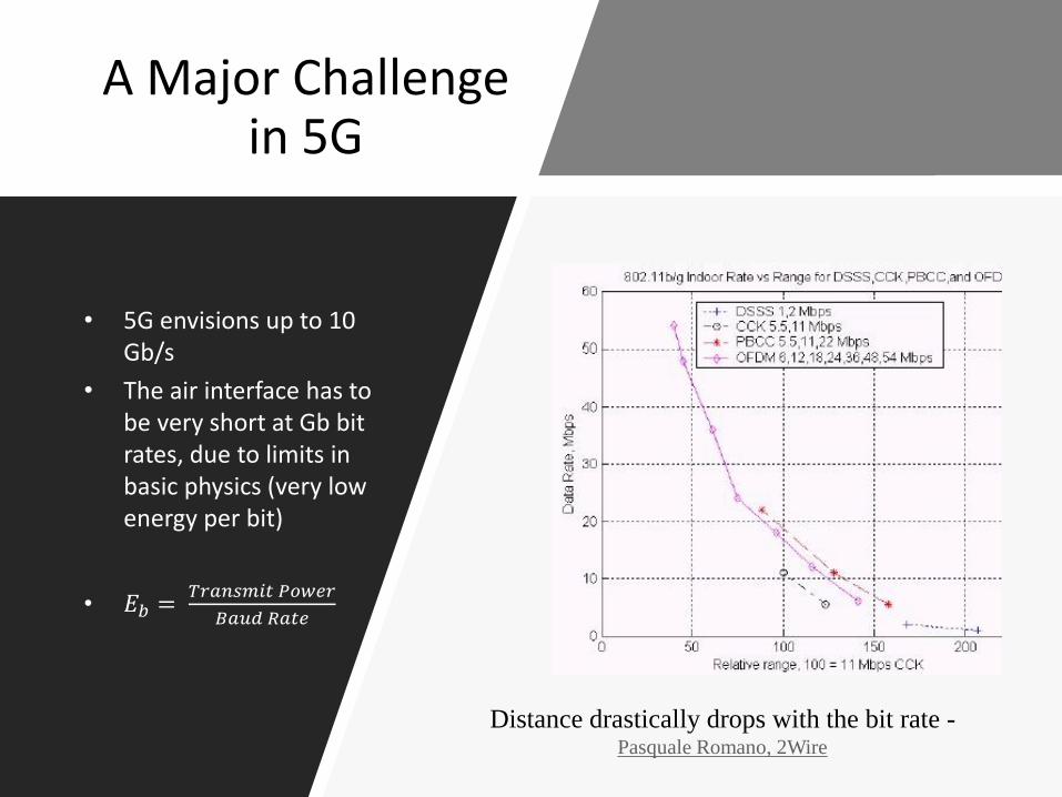
• 5G envisions up to 10 Gb/s
• The air interface has to be very short at Gb bit rates, due to limits in basic physics (very low energy per bit)
• 𝐸𝑏 =𝑇𝑟𝑎𝑛𝑠𝑚𝑖𝑡 𝑃𝑜𝑤𝑒𝑟
𝐵𝑎𝑢𝑑 𝑅𝑎𝑡𝑒
Distance drastically drops with the bit rate -Pasquale Romano, 2Wire
Optical Techniques
• Bring the radio access points closer to the user
– Fiber-Wireless (Radio over Fiber) systems
– Optical feeders for distributed antennas
– Integration with PON and, HFC networks
• Optical wireless techniques
– Visible light communications (VLC)
– Infrared wireless communications
– Point to point/Distributed
– Indoor/outdoor
Key Issues in OW
• Primarily for downlink – IOT needs more uplink
• Line of sight and short range
• Very short channel coherent time (outdoors)
• Detection issue. Optical reception is difficult than RF receivers
• High level of ambient light noise (SNR < 0)
• Intensity modulated optical signals are scalars.
– Only the Amplitude can be changed (Unipolar) while radio signals are vectors
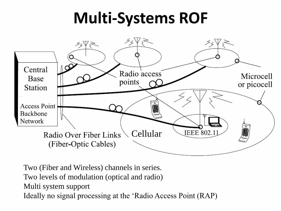
Multi-Systems ROF
Two (Fiber and Wireless) channels in series.
Two levels of modulation (optical and radio)
Multi system support
Ideally no signal processing at the ‘Radio Access Point (RAP)
Cellular
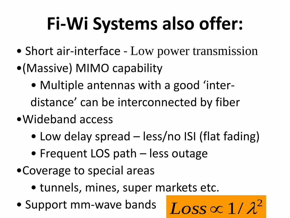
• Short air-interface - Low power transmission
•(Massive) MIMO capability
• Multiple antennas with a good ‘inter-
distance’ can be interconnected by fiber
•Wideband access
• Low delay spread – less/no ISI (flat fading)
• Frequent LOS path – less outage
•Coverage to special areas
• tunnels, mines, super markets etc.
• Support mm-wave bands
Fi-Wi Systems also offer:
2/1 Loss
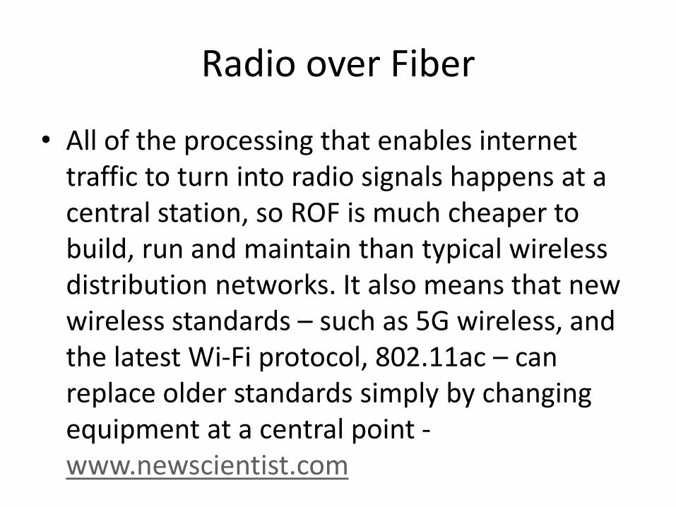
Radio over Fiber
• All of the processing that enables internet traffic to turn into radio signals happens at a central station, so ROF is much cheaper to build, run and maintain than typical wireless distribution networks. It also means that new wireless standards – such as 5G wireless, and the latest Wi-Fi protocol, 802.11ac – can replace older standards simply by changing equipment at a central point -www.newscientist.com
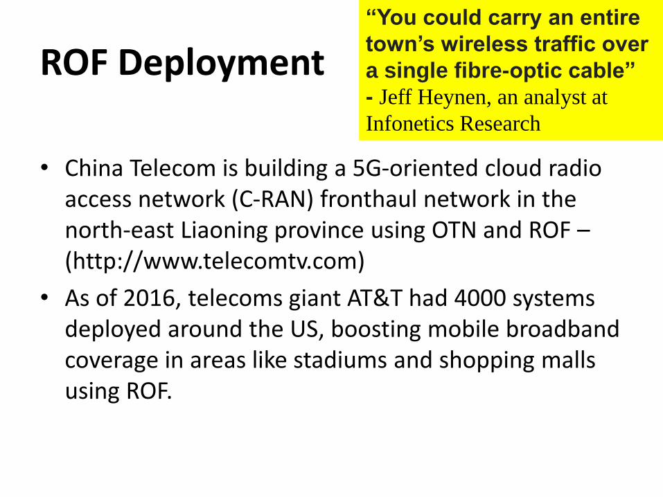
“You could carry an entire
town’s wireless traffic over
a single fibre-optic cable”
- Jeff Heynen, an analyst at
Infonetics Research
ROF Deployment
• China Telecom is building a 5G-oriented cloud radio access network (C-RAN) fronthaul network in the north-east Liaoning province using OTN and ROF –(http://www.telecomtv.com)
• As of 2016, telecoms giant AT&T had 4000 systems deployed around the US, boosting mobile broadband coverage in areas like stadiums and shopping malls using ROF.
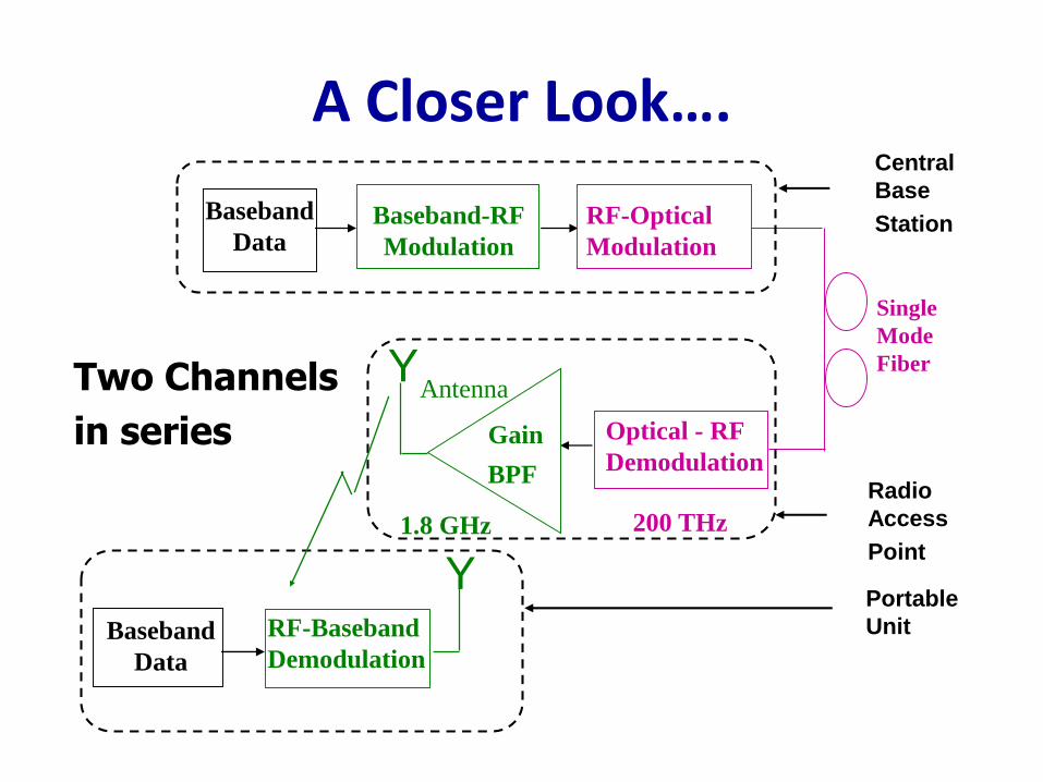
A Closer Look….
Y
Single
Mode
Fiber
Baseband
DataBaseband-RF
Modulation
RF-Optical
Modulation
Optical - RF
DemodulationGain
BPF
Antenna
200 THz1.8 GHz
RF-Baseband
Demodulation
YBaseband
Data
Radio
Access
Point
Central
Base
Station
Portable
Unit
Two Channels
in series
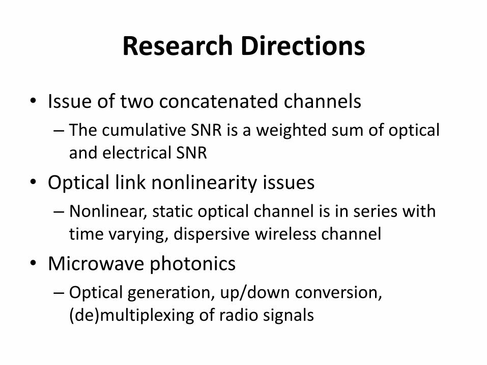
Research Directions
• Issue of two concatenated channels
– The cumulative SNR is a weighted sum of optical and electrical SNR
• Optical link nonlinearity issues
– Nonlinear, static optical channel is in series with time varying, dispersive wireless channel
• Microwave photonics
– Optical generation, up/down conversion, (de)multiplexing of radio signals
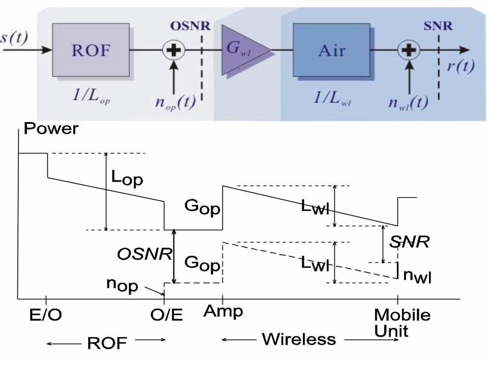
AM-AM & AM-PM Distortion
0
0.1
0.2
0.3
0.4
0.5
0.6
0.7
0.8
0 0.5 1 1.5 2 2.5 3 3.5
Input RF Power (mW)
Ou
tpu
t R
F P
ow
er
(mW
)
0
20
40
60
80
100
120
140
160
Ph
as
e S
hif
t (D
eg
ree
s)
Output Power (mW) Phase (Deg)
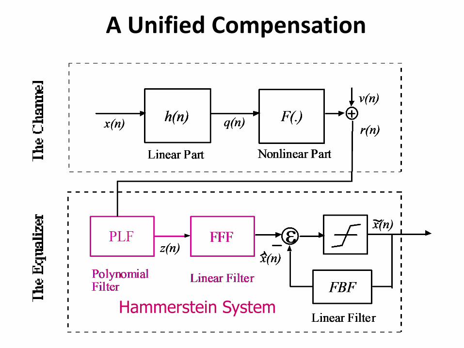
A Unified Compensation
Hammerstein System
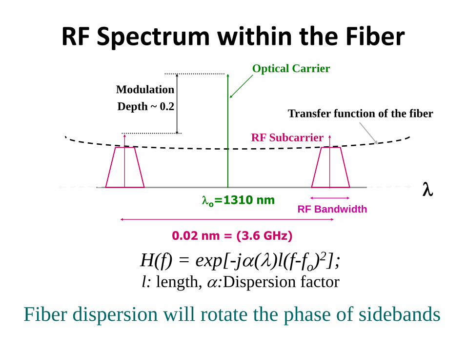
Fiber dispersion will rotate the phase of sidebands
o=1310 nm
0.02 nm = (3.6 GHz)
Transfer function of the fiber
Optical Carrier
RF Subcarrier
RF Bandwidth
Modulation
Depth ~ 0.2
RF Spectrum within the Fiber
H(f) = exp[-j()l(f-fo)2];
l: length, :Dispersion factor
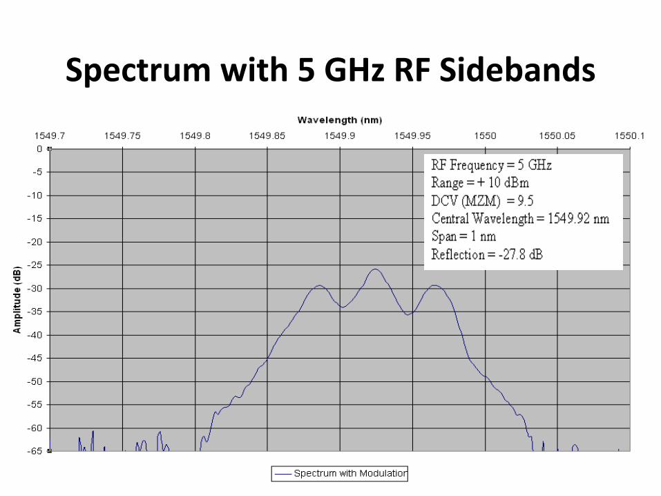
Spectrum with 5 GHz RF Sidebands
Tuesday, October 31, 2017
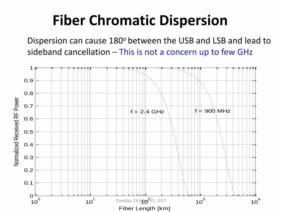
Fiber Chromatic DispersionDispersion can cause 180o between the USB and LSB and lead to sideband cancellation – This is not a concern up to few GHz
100
101
102
103
104
0
0.1
0.2
0.3
0.4
0.5
0.6
0.7
0.8
0.9
1
Fiber Length [km]
Nor
mal
ized
Rec
eive
d R
F P
ower
f = 2.4 GHz f = 900 MHz
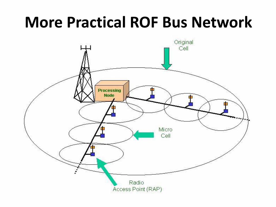
More Practical ROF Bus Network
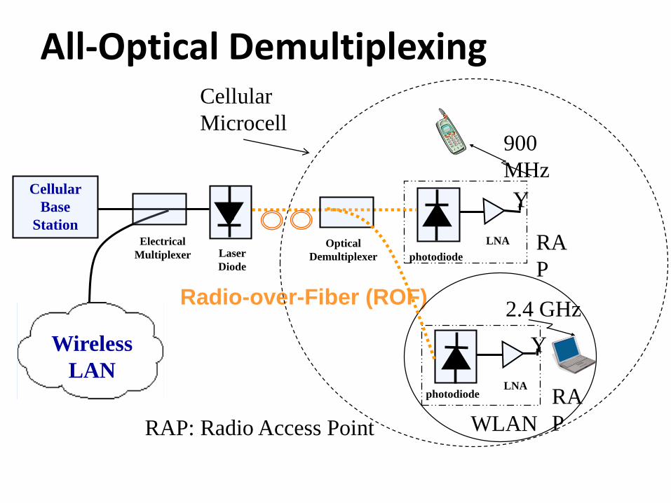
All-Optical Demultiplexing
Radio-over-Fiber (ROF)
Cellular
Microcell900
MHz
WLAN
2.4 GHz
Electrical
MultiplexerOptical
Demultiplexer
Cellular
Base
Stations
Laser
Diode
Y
LNA
Y
LNA
photodiode
photodiode
RA
P
RA
PRAP: Radio Access Point
Wireless
LAN
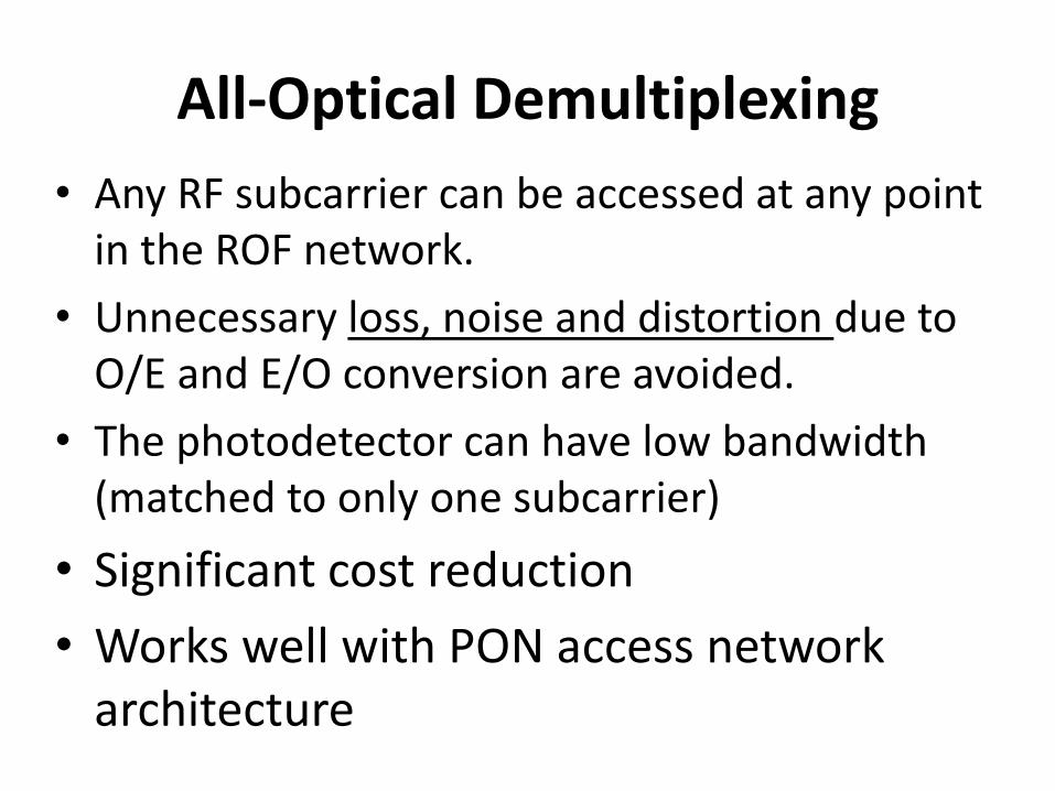
All-Optical Demultiplexing
• Any RF subcarrier can be accessed at any point in the ROF network.
• Unnecessary loss, noise and distortion due to O/E and E/O conversion are avoided.
• The photodetector can have low bandwidth (matched to only one subcarrier)
• Significant cost reduction
• Works well with PON access network architecture
Tuesday, October 31, 2017
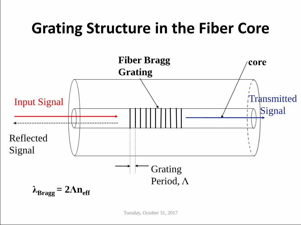
Grating Structure in the Fiber Core
Fiber Bragg
Grating
Input Signal
Reflected
Signal
Transmitted
Signal
Grating
Period, ΛλBragg = 2Λneff
Tuesday, October 31, 2017
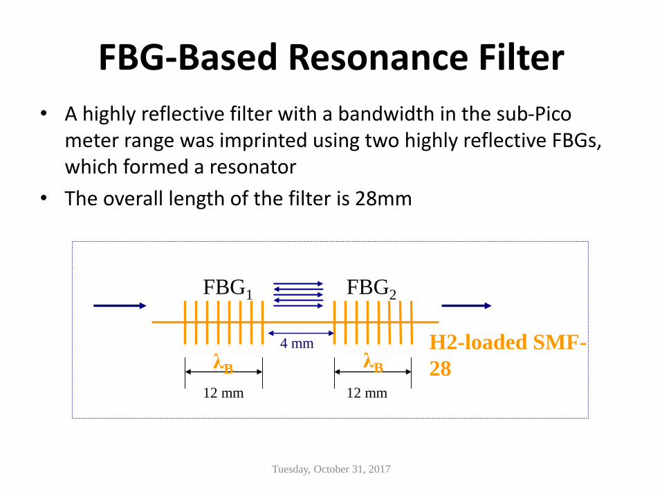
• A highly reflective filter with a bandwidth in the sub-Pico meter range was imprinted using two highly reflective FBGs, which formed a resonator
• The overall length of the filter is 28mm
FBG-Based Resonance Filter
FBG1 FBG2
12 mm 12 mm
4 mm H2-loaded SMF-
28λB λB
Tuesday, October 31, 2017
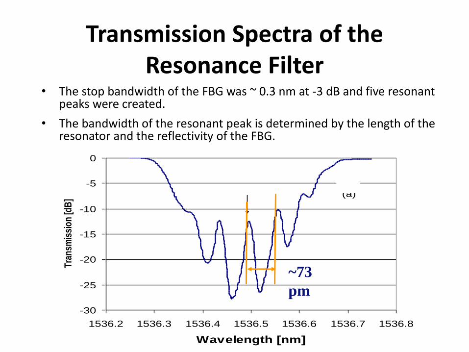
Transmission Spectra of the Resonance Filter
• The stop bandwidth of the FBG was ~ 0.3 nm at -3 dB and five resonant peaks were created.
• The bandwidth of the resonant peak is determined by the length of the resonator and the reflectivity of the FBG.
-30
-25
-20
-15
-10
-5
0
1536.2 1536.3 1536.4 1536.5 1536.6 1536.7 1536.8
Wavelength [nm]
Tra
nsm
issi
on
[dB
] (a)
~73
pm
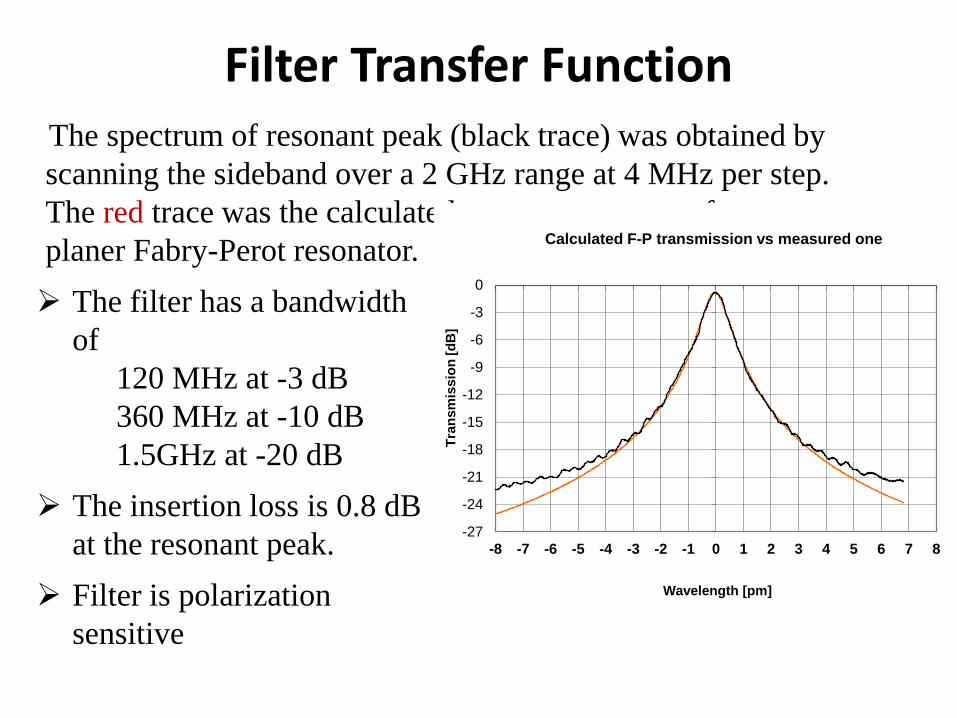
Filter Transfer FunctionThe spectrum of resonant peak (black trace) was obtained by
scanning the sideband over a 2 GHz range at 4 MHz per step.
The red trace was the calculated resonant spectrum from a
planer Fabry-Perot resonator.
The filter has a bandwidth
of
120 MHz at -3 dB
360 MHz at -10 dB
1.5GHz at -20 dB
The insertion loss is 0.8 dB
at the resonant peak.
Filter is polarization
sensitive
-27
-24
-21
-18
-15
-12
-9
-6
-3
0
-8 -7 -6 -5 -4 -3 -2 -1 0 1 2 3 4 5 6 7 8
Tra
ns
mis
sio
n [
dB
]
Wavelength [pm]
Calculated F-P transmission vs measured one
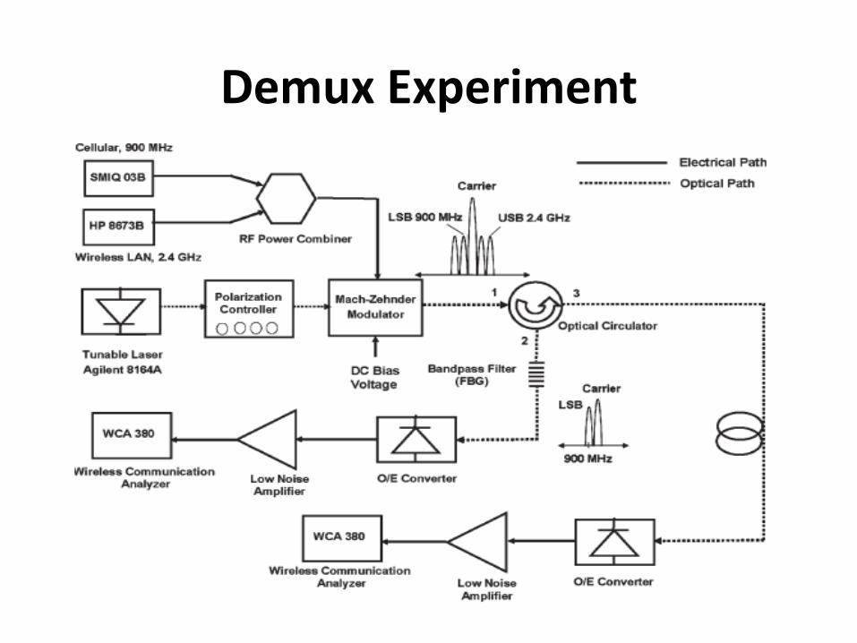
Demux Experiment
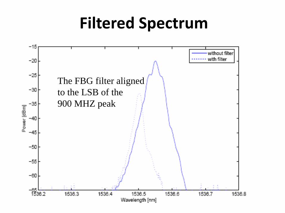
Filtered Spectrum
The FBG filter aligned
to the LSB of the
900 MHZ peak
Tuesday, October 31, 2017
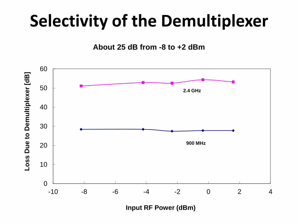
Selectivity of the Demultiplexer
0
10
20
30
40
50
60
-10 -8 -6 -4 -2 0 2 4
Lo
ss
Du
e t
o D
em
ult
iple
xer
[dB
]
Input RF Power (dBm)
About 25 dB from -8 to +2 dBm
2.4 GHz
900 MHz
Tuesday, October 31, 2017
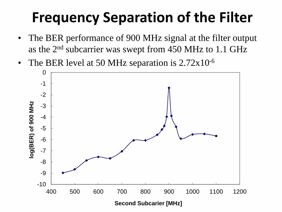
Frequency Separation of the Filter
-10
-9
-8
-7
-6
-5
-4
-3
-2
-1
0
400 500 600 700 800 900 1000 1100 1200
log
(BE
R)
of
90
0 M
Hz
Second Subcarier [MHz]
• The BER performance of 900 MHz signal at the filter output
as the 2nd subcarrier was swept from 450 MHz to 1.1 GHz
• The BER level at 50 MHz separation is 2.72x10⁻⁶
o=1310 nm
0.02 nm = (3.6 GHz)
Transfer function of the fiber
Optical Carrier
RF Subcarrier
RF Bandwidth
Modulation
Depth ~ 0.2
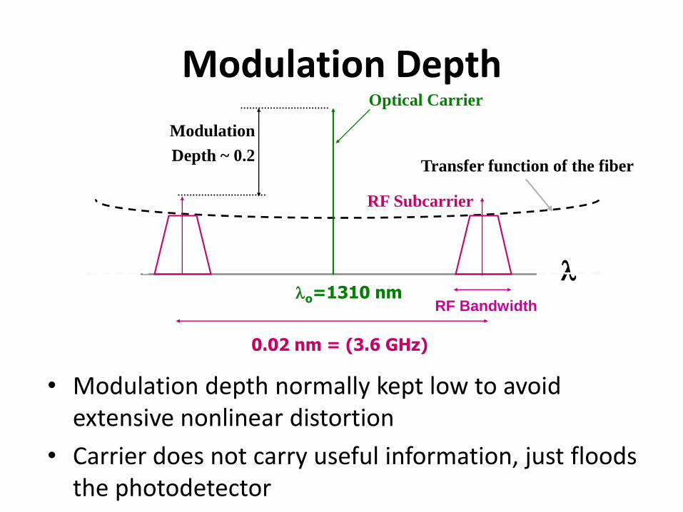
Modulation Depth
• Modulation depth normally kept low to avoid extensive nonlinear distortion
• Carrier does not carry useful information, just floods the photodetector
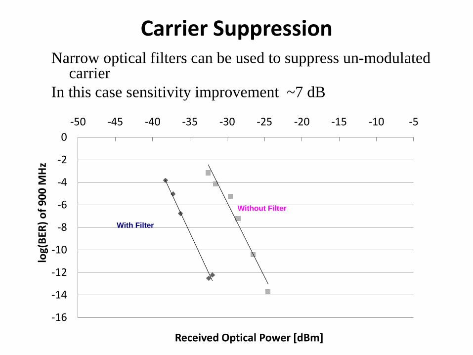
Carrier Suppression
-16
-14
-12
-10
-8
-6
-4
-2
0
-50 -45 -40 -35 -30 -25 -20 -15 -10 -5
log(
BER
) o
f 9
00
MH
z
Received Optical Power [dBm]
With Filter
Without Filter
Narrow optical filters can be used to suppress un-modulated carrier
In this case sensitivity improvement ~7 dB
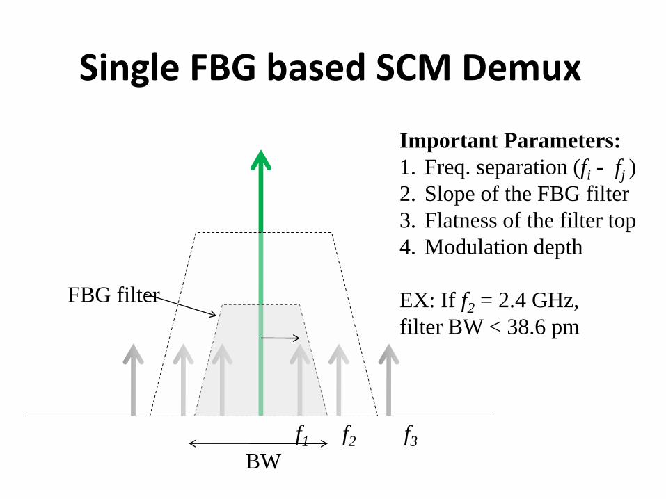
Single FBG based SCM Demux
f1 f2 f3
Important Parameters:
1. Freq. separation (fi - fj )
2. Slope of the FBG filter
3. Flatness of the filter top
4. Modulation depth
EX: If f2 = 2.4 GHz,
filter BW < 38.6 pm
FBG filter
BW
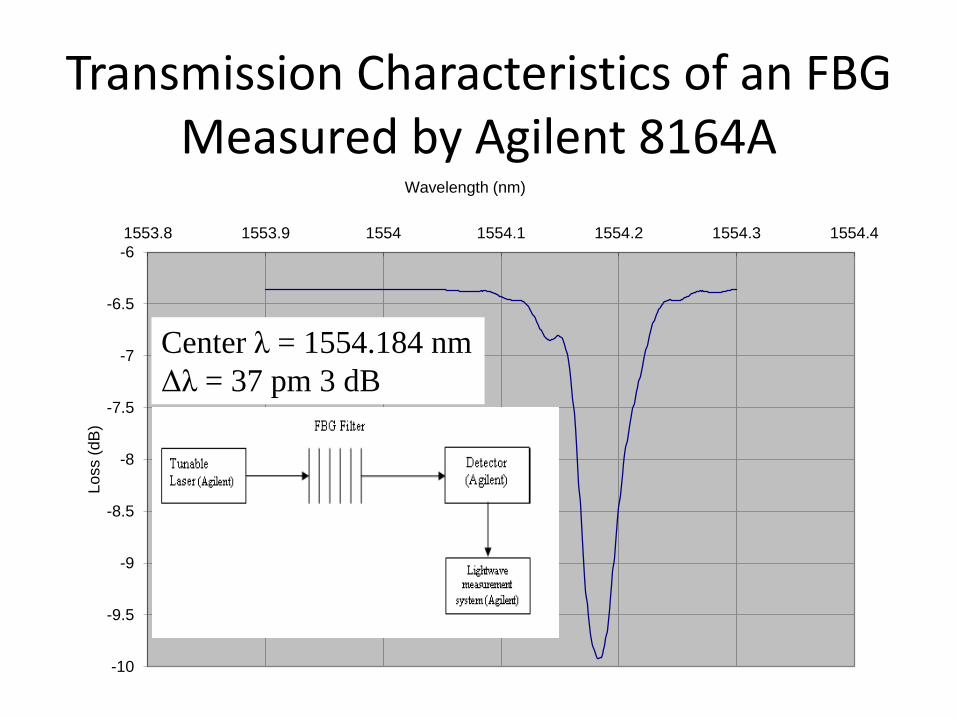
Transmission Characteristics of an FBG Measured by Agilent 8164A
-10
-9.5
-9
-8.5
-8
-7.5
-7
-6.5
-6
1553.8 1553.9 1554 1554.1 1554.2 1554.3 1554.4
Lo
ss (
dB
)
Wavelength (nm)
Center λ = 1554.184 nm
Δλ = 37 pm 3 dB
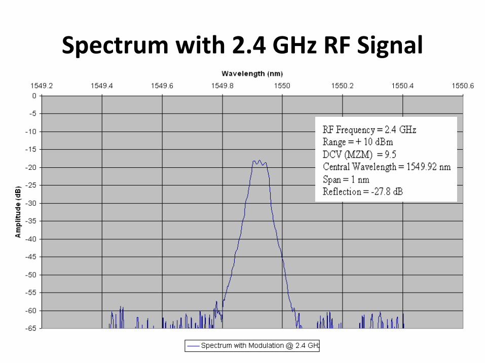
Spectrum with 2.4 GHz RF Signal
Conclusions
• Radio over Fiber is an attractive approach for wideband wireless access
• Fiber has ample bandwidth
• Lots of existing dim/dark fiber
• Supporting multiple standards is possible
• Major concerns are– High loss and noise due to concatenated channels
– Nonlinear distortion and limited dynamic range of the ROF link
• Some emerging areas like coherent modulation will improve the situation