optical networks survivability - ufpa · optical networks, survivability, cicek cavdar, kth 7...
TRANSCRIPT

Optical Networks Survivability
6 September 2012, Belem, Para, Brazil Dr. Cicek Cavdar, [email protected]
Optical Networks Lab (ONLab) Royal Institute of Technology, Stockholm, Sweden
Special thanks to Biswanath Mukherjee from UC-Davis, Aysegul Yayimli from ITU, for the class material.

Optical Networks, Survivability, Cicek Cavdar, KTH 2
Introduction n Equipment failures may occur in a network and
disrupt traffic. n A duct is a bidirectional physical pipe between
two nodes. ¨ In practice, fibers are put into cables, which are buried
into ducts under the ground. n A fiber cut usually occurs due to a duct cut
during construction or destructive natural events, such as earthquakes, etc.
n All the lightpaths that traverse the failed fiber will be disrupted. ¨ A fiber cut can lead to tremendous traffic loss.

Optical Networks, Survivability, Cicek Cavdar, KTH 3
Types of Failure

Optical Networks, Survivability, Cicek Cavdar, KTH 4
Types of Failures n If a fiber supports:
¨ 160 wavelength channels, ¨ each wavelength operating at 10 Gbps (OC-192),
a fiber cut can lead to 1.6 Tbps data loss. n Fiber is laid in bundles (cables),
¨ each cable carrying as many as 864 fiber strands, ¨ each duct carrying many bundles
(perhaps 10 or higher), a duct cut can lead to huge data loss.
Optical Networks, Survivability, Cicek Cavdar, KTH 5
Types of Failure n A central office (CO) can also fail where OXCs
are located, because of catastrophic events such as fire or flooding. This is referred to as node failure.
n Node failures are rare but the disruption will be very significant if it occurs.
n Channel failure is also possible in optical WDM networks. ¨ Caused by the failure of transmitting and/or receiving
equipment operating on that channel.

Optical Networks, Survivability, Cicek Cavdar, KTH 6
Failure Rates n The table shows some typical data on network
component failure rates and failure-repair times, according to Bellcore. § FIT (failure-in-time): the average number of failures in 109 hours § Tx: optical transmitters § Rx: optical receivers § MTTR: mean time to repair.

Optical Networks, Survivability, Cicek Cavdar, KTH 7
Network Survivability n Network survivability becomes a critical concern
in network design and its real-time operation. ¨ High frequency of fiber cut, and ¨ The tremendous traffic loss a failure may cause.
n We need to design effective methods to recover from failures of network links and nodes.
n An individual channel failure can be handled locally: ¨ by quickly switching to another idle local channel, ¨ or, as a link failure when no idle channel is available.

Optical Networks, Survivability, Cicek Cavdar, KTH 8
Single vs. Multiple Failures n Most of the research work on survivability in
WDM networks focus on the recovery from a single link or node failure. ¨ One failure is repaired before another failure is
assumed to occur in the network. ¨ This is known as the assumption of single failure
scenario. n Multiple, near-simultaneous failures are also
possible in a realistic network, and appropriate recovery methods can be designed.
Optical Networks, Survivability, Cicek Cavdar, KTH 9
Shared Risk Groups n Shared Risk Groups (SRG) express the risk relationship
that associates all the optical channels with a single failure.
n An SRG may consist of: ¨ all optical channels in a single fiber ¨ all optical channels through all the fibers wrapped in the same
cable n Since a fiber may run through several conduits, an
optical channel may belong to several SRG. n The provisioning algorithms must exploit SRG maps to
discover SRG-diverse routes so that, after any conduit is cut, there is always at least one viable route remaining.
n This constraint is the SRG constraint.
Optical Networks, Survivability, Cicek Cavdar, KTH 10
Shared-Risk Link Group n The SRG concept can be generalized to include
a group of nodes and links that are in close proximity.
n A large scale disaster covering a wide geographical region may disrupt all members of the SRG simultaneously.
n Since link failure is the dominant failure scenario, shared-risk link group (SRLG) is a commonly-used form of SRG.
Optical Networks, Survivability, Cicek Cavdar, KTH 11
Fault Management n Survivability can be provided in many layers in
the network. ¨ e.g., ATM, IP, SONET/SDH.
n The fault-management schemes in each layer have their own functionalities and characteristics.
n In an optical network, line terminals can detect the failures in milliseconds: ¨ a loss of signal on an optical link or a high bit-error
rate (BER).
Fault Management n The optical layer can handle some faults more
efficiently. ¨ A fiber cut results in the loss of all the traffic streams
carried by the fiber. ¨ Without optical-layer protection, each traffic stream
will be restored independently by the client layers. ¨ The network-management system may be flooded
with a large number of messages (failure notification, traffic rerouting, etc.) for this single failure.
n Fewer entities need to be rerouted if the optical layer can quickly restore the traffic.
Optical Networks, Survivability, Cicek Cavdar, KTH 12
Optical Networks, Survivability, Cicek Cavdar, KTH 13
Fault Management in WDM Mesh Networks n There are two types of fault-recovery
mechanisms: ¨ protection ¨ restoration.
n If backup resources (routes and wavelengths) are pre-computed and reserved in advance, we call it a protection scheme.
n If another route and a free wavelength have to be discovered dynamically whenever a failure occurs, we call it a restoration scheme.

Optical Networks, Survivability, Cicek Cavdar, KTH 14
Protection vs. Restoration n Dynamic restoration schemes are more efficient
in utilizing network capacity. ¨ They do not allocate spare capacity in advance, ¨ They provide resilience against different kinds of
failures (including multiple failures). n Protection schemes have faster recovery time.
¨ They can guarantee recovery from disrupted services they are designed to protect against.
Optical Networks, Survivability, Cicek Cavdar, KTH 15
Path vs. Link Protection n protection can be divided into two groups:
¨ path protection ¨ link protection.
n In path protection, the traffic is rerouted through a backup route once a link failure occurs on its working (primary) path.
n The primary and backup paths for a connection must be link-disjoint. ¨ No single link failure can affect both of these paths.
n In link protection, the traffic is rerouted only around the failed link.
n Path protection leads to efficient utilization of backup resources and lower end-to-end propagation delay for the recovered route.
n Link protection provides faster protection-switching time.

Optical Networks, Survivability, Cicek Cavdar, KTH 16
Path vs. Link Protection

Optical Networks, Survivability, Cicek Cavdar, KTH 17
Dedicated vs. Shared Protection n Protection schemes can be:
¨ dedicated, or ¨ shared.
n In dedicated protection, sharing is not allowed between backup bandwidth.
n In shared protection, backup bandwidth can be shared on some links, ¨ as long as their protected segments (links, paths) are mutually
diverse or not in the same SRG. n OXCs on backup paths are not configured until the
failure occurs if shared protection is used. n So, recovery time in shared protection is longer
but it can achieve better resource efficiency than dedicated protection.

Optical Networks, Survivability, Cicek Cavdar, KTH 18
1+1 Protection In dedicated protection: n If traffic is transmitted simultaneously on both
primary and backup paths, the destination simply selects one of the two signals for reception.
n If one path is cut, the destination switches over to the other path and continues to receive the data.
n This form of protection is usually referred to as 1+1 protection. ¨ Provides very fast recovery and requires no signaling
protocol between the two end nodes.

Optical Networks, Survivability, Cicek Cavdar, KTH 19
1:1 Protection n Traffic is only transmitted on the primary path,
the source and destination nodes both switch over to the backup path when the primary path is cut.
n This form of protection is referred to as 1:1 protection. ¨ The backup bandwidth can be used to carry low-
priority preemptable traffic during normal operation. n Shared protection scheme is also referred to as
M:N protection. ¨ M primary paths may share N backup paths.

Optical Networks, Survivability, Cicek Cavdar, KTH 20
Example

Optical Networks, Survivability, Cicek Cavdar, KTH 21
Example

Optical Networks, Survivability, Cicek Cavdar, KTH 22
Example

Optical Networks, Survivability, Cicek Cavdar, KTH 23
Reverting vs. Non-reverting n Protection schemes can be:
¨ reverting or ¨ non-reverting.
n In both schemes, if a failure occurs, traffic is switched from the primary path to the backup path.
n In reverting, the traffic is switched back to its primary path after the failure on the primary path is repaired.
n In non-reverting, the traffic stays on the backup path for the remaining service time.
n Reverting allows the network to return to its original state once the failure is restored.

Optical Networks, Survivability, Cicek Cavdar, KTH 24
Reverting, Non-reverting n Dedicated protection schemes can be either
reverting or non-reverting. n Only reverting may be applied for a shared
protection scheme. n Since multiple connections are sharing the
common backup bandwidth, the backup bandwidth must be freed up as soon as possible after the original failure has been repaired.
n Reverting, however, will cause an additional distraction on the data flow.
Optical Networks, Survivability, Cicek Cavdar, KTH 25
Restoration n Dynamic restoration can be classified as link, sub-path,
or path based, depending on the type of rerouting. n In link restoration, the end nodes of the failed link
dynamically discover a route around the link, for each connection that traverses the link.
n In path restoration, when a link fails, the source and the destination node of each connection that traverses the failed link are informed about the failure. ¨ The source and destination nodes of each connection
independently discover a backup route on an end-to-end basis. n In sub-path restoration, when a link fails, the upstream
node of the failed link detects the failure and discovers a backup route from itself to the corresponding destination node for each disrupted connection.

Optical Networks, Survivability, Cicek Cavdar, KTH 26
Summary

Optical Networks, Survivability, Cicek Cavdar, KTH 27
Fault Management in SONET n SONET networks can provide high availability to end-to-
end connections through the use of extensive protection techniques.
n This requires a signaling protocol, called an automatic protection-switching (APS) protocol.
n Much of the carrier infrastructure today uses SONET/SDH rings. ¨ Multiple nodes are interconnected with a single physical ring.
n A ring is a 2-connected topology, and provides two disjoint paths between any pair of nodes that do not have any nodes or links in common except the source and destination nodes.
n These rings are called self-healing rings (SHRs). ¨ They can automatically detect failures and quickly reroute traffic
away from failed links or nodes by using the other half of the ring.
Optical Networks, Survivability, Cicek Cavdar, KTH 28
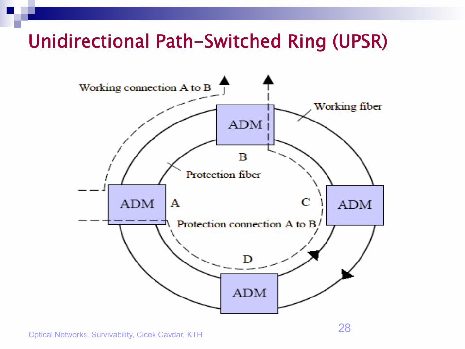
Unidirectional Path-Switched Ring (UPSR)

Optical Networks, Survivability, Cicek Cavdar, KTH 29
UPSR n The adjacent nodes are connected by two fibers. n For example:
¨ The fiber in the clockwise direction may be used as the working fiber and
¨ The other in the counter-clockwise direction is used as the protection fiber.
n For each SONET connection, traffic is sent both on the working fiber and on the protection fiber.
n The destination monitors both the working and protection fibers and selects the better signal between the two.
n Suppose that the destination receives traffic from the working fiber under normal operation. ¨ If there is a link or node failure on the working path, the
destination will switch over to the protection fiber and continue to receive the data.
Optical Networks, Survivability, Cicek Cavdar, KTH 30
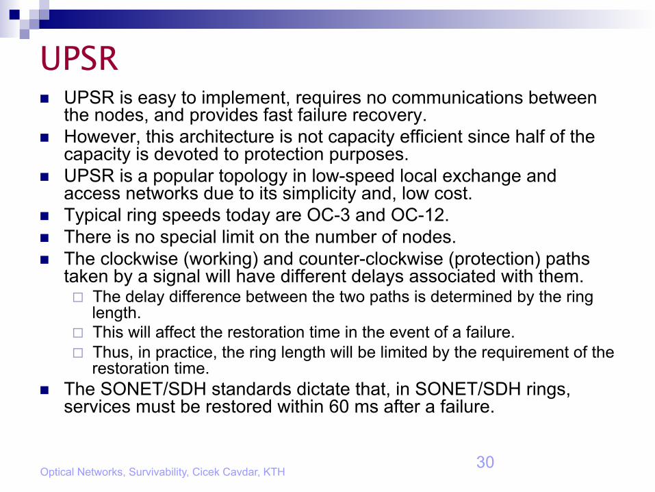
UPSR n UPSR is easy to implement, requires no communications between
the nodes, and provides fast failure recovery. n However, this architecture is not capacity efficient since half of the
capacity is devoted to protection purposes. n UPSR is a popular topology in low-speed local exchange and
access networks due to its simplicity and, low cost. n Typical ring speeds today are OC-3 and OC-12. n There is no special limit on the number of nodes. n The clockwise (working) and counter-clockwise (protection) paths
taken by a signal will have different delays associated with them. ¨ The delay difference between the two paths is determined by the ring
length. ¨ This will affect the restoration time in the event of a failure. ¨ Thus, in practice, the ring length will be limited by the requirement of the
restoration time. n The SONET/SDH standards dictate that, in SONET/SDH rings,
services must be restored within 60 ms after a failure.

Optical Networks, Survivability, Cicek Cavdar, KTH 31
Bidirectional Line-Switched Ring (BLSR)

Optical Networks, Survivability, Cicek Cavdar, KTH 32
BLSR n Two adjacent nodes in the ring are connected by four fibers,
¨ two for working traffic and ¨ two for protection traffic.
n The traffic between two nodes will be routed via the shortest path. n For example, the traffic for node A to node B is routed clockwise and
the traffic from B to A is routed counter-clockwise. n When a working fiber fails, the traffic is routed onto the protection
fiber between the two nodes on the same link. n This scheme is referred to as span switching. n If the working fibers and protection fibers between two nodes fail
simultaneously, which is the common case since the working fibers and the protection fibers between two nodes are usually routed jointly, the traffic between the two nodes is routed around the ring on the protection fiber.
n This scheme is referred to as ring switching.
Optical Networks, Survivability, Cicek Cavdar, KTH 33
Ring Cover in WDM Mesh Networks n Optical networks based on a single physical ring
are favored for their fast restoration since rings use a simple switching mechanism which permits restoration in about 50-60 ms.
n Unfortunately, they are rather capacity-inefficient and require at least 100% capacity redundancy by their nature.
n Mesh-based networks require much less spare capacity but more complex protection mechanisms are required, which leads to slow restoration speed.
Ring Cover in WDM Mesh Networks n To achieve the restoration speed of rings in a
mesh-based network topology, one solution is to cover the whole physical mesh network using multiple logical rings.
n This scheme is referred to as ring cover scheme. n In the logical rings, nodes are still physical
nodes but links are usually composed of one or multiple wavelength channels.
n The imposed logical rings may behave like physical self-healing rings by themselves or may be used only for protection purpose.
Optical Networks, Survivability, Cicek Cavdar, KTH 34
Optical Networks, Survivability, Cicek Cavdar, KTH 35
Ring Cover n If the logical rings behave like physical self-healing rings,
both UPSR and BLSR- style covers can be applied. n The end-to-end traffic in the mesh network falls into two
types: ¨ intra-ring traffic and ¨ inter-ring traffic.
n The intra-ring traffic is operated as regular traffic in a single self-healing ring.
n The inter-ring traffic is more expensive. ¨ Extra switching and add/drop operations are needed at the node
crossed over by two or more rings. n The inter-ring traffic is segmented by the rings it
traverses, and each segment is protected by the bandwidth in the same ring.
Optical Networks, Survivability, Cicek Cavdar, KTH 36
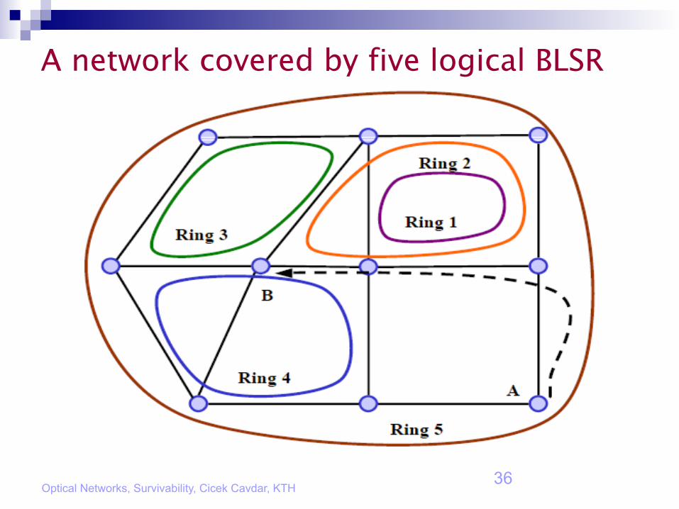
A network covered by five logical BLSR

Optical Networks, Survivability, Cicek Cavdar, KTH 37
Stacked Rings n In the figure:
¨ Node A and node B are not covered by the same ring: ¨ So, the traffic from node A to node B needs to traverse multiple rings. ¨ Traffic from node A to node B can be routed via rings 5 and 2. ¨ It can also take other routes through other rings: using ring 5 and 4.
n This type of interconnected logical rings is usually called stacked rings.
n In the horizontal dimension, adjacent rings provide extended geographic coverage compared to a single physical ring.
n In the vertical dimension, the rings are stacked on top of each other on some links, thereby providing increased network capacity for the area covered by the ring stack.
n This vertical stacking is achieved through the use of WDM. ¨ One fiber can carry multiple, stacked rings by using different
wavelengths to transmit the data.

Optical Networks, Survivability, Cicek Cavdar, KTH 38
Protection Cycle n Protection cycle (p-cycle) has been investigated in recent
years as a variation of ring-cover techniques. n In a p-cycle, not only these on-cycle links could be
protected by each other in a self-healing-ring manner, but the chordal (or straddling links) could also be protected.
n A straddling link is an off-cycle link having p-cycle nodes as end-points.
n In the case of a straddling link failure, two node-disjoint paths around the p-cycle running between the two end nodes can be used to protect the failed link.
n A p-cycle can be more capacity-efficient than a BLSR or UPSR since the on cycle capacity is used to protect both on-cycle link failures and the failures of straddling links.

Optical Networks, Survivability, Cicek Cavdar, KTH 39
P-Cycles
Optical Networks, Survivability, Cicek Cavdar, KTH 40
Survivable Routing and Wavelength Assignment (S-RWA) n The problem of finding a link-disjoint primary-backup
path pair and assigning a proper wavelength channel to each path is known as the survivable routing and wavelength assignment (S-RWA) problem.
n Usually, a path-pair with least cost from a source to a destination is preferred to carry the traffic with protection.
n The path cost for an unprotected lightpath is defined to be the sum of the costs of the links on the path.
n Similarly, the path cost of a dedicated-path-protected connection is the sum of the costs of the primary and backup lightpaths.

Optical Networks, Survivability, Cicek Cavdar, KTH 41
S-RWA n The path-pair can be:
¨ Selected from a set of preplanned alternate routes, or ¨ Dynamically computed according to current network state.
n Depending on different traffic-engineering considerations for dynamic traffic, different cost functions can be applied to network links: ¨ constant 1 (to minimize hop distance), ¨ the length of the links (to minimize propagation delay), ¨ the fraction of the available capacity on the links (to balance
network load), ¨ the network cost (total equipment cost plus operational cost) on
the links (to minimize cost), ¨ etc.

Optical Networks, Survivability, Cicek Cavdar, KTH 42
S-RWA n The wavelength-assignment (WA) problem can be
considered after the routing of the pair of primary-backup paths has been fixed.
n Different WA heuristics have been proposed in the literature.
n WA can also be jointly considered with the route computation of both primary and backup paths.
n The problem of computing a pair of link-disjoint paths in a WDM network with wavelength-continuity constraint is NP-complete.
n When a network has full wavelength-conversion capability, the problem is reduced to an optimal routing problem for a link-disjoint path pair.

Optical Networks, Survivability, Cicek Cavdar, KTH 43
Computing Link-Disjoint Paths n Two-step algorithm:
¨ The primary path is computed using a shortest-path algorithm. ¨ The edges along the primary path are removed. ¨ The backup path is computed by finding a shortest path in the
reduced graph. n The two-step algorithm has some potential weaknesses:
¨ Its computation is sequential, and ¨ It does not allow backtracking to re-compute the primary path if
necessary. n As a result, it may not always find a pair of link-disjoint
paths between the source and the destination nodes even if such paths exist.
n Also, the paths found by the two-step algorithm may not be optimal, i.e., the total cost of the two paths may not be minimal.

Optical Networks, Survivability, Cicek Cavdar, KTH 44
Example n An example where the two-step algorithm fails to
compute a pair of link-disjoint paths from node 0 to node 5.
n Such a pair of paths actually exists.

Optical Networks, Survivability, Cicek Cavdar, KTH 45
Bhandari’s Algorithm n A polynomial time algorithm for simultaneously
computing two link-disjoint paths between a node pair. (Also referred to as the one-step algorithm.)
n The total cost of the two paths computed by this algorithm has been proved to be minimum. ¨ We refer to this path pair as the Optimal Path Pair (OPP).

Optical Networks, Survivability, Cicek Cavdar, KTH 46
Example n Numbers next to links in the figure represent link costs. n Number next to a node u represent the shortest path
distance between the nodes 0 and u: d(0, u). n The dashed line gives the shortest-path tree rooted at
node 0. n We can determine that the shortest path from node 0 to
node 5 is T = (0, 1, 4, 5). n After graph transformation, the shortest path between
nodes 0 and 5 is T = (0, 3, 4, 1, 2, 5). n After removing the interlacing link (1, 4), (c) shows the
two link-disjoint paths (0, 3, 4, 5) and (0, 1, 2, 5).

?
For questions, please send e-mail: [email protected]
Note: In the presentation, most material are cited from related sources. Since some material cited here may be confidential, or not be allowed to be circulated, please directly contact their own sources if you will use them.
Optical Networks, Survivability, Cicek Cavdar, KTH