optical networks - İtÜweb.itu.edu.tr/~gencata/courses/on/onslides/onintro.pdfthis trend gave rise...
TRANSCRIPT
A. YayımlıİTÜ, Dept. Computer Engineering
2016
OPTICAL NETWORKS
Introduction
2
Optical Networking In the 1980s telecommunications carriers began
migrating much of the physical layer of their intercity networks to fiberoptic cable.
Optical fiber is a lightweight cable that provides low-loss transmission.
Its most significant benefit is its tremendous potential capacity.
This trend gave rise to optical networks and the field of optical networking.
3
Optical Networking An optical network is composed of the fiber-optic
cables that carry channels of light. The cables are combined with the optical
components deployed along the fiber to process the light.
The capabilities of an optical network are necessarily tied to the physics of light, and the technologies for manipulating lightstreams.
4
WDM One of the earliest technological advances was the
ability to carry multiple channels of light on a single fiber. Each lightstream, or wavelength, is carried at a different
optical frequency and multiplexed (= combined) onto a single fiber.
This is known as wavelength division multiplexing (WDM).
The earliest WDM systems supported fewer than ten wavelengths on a single fiber.
Since 2000, this number has rapidly grown to over 100 wavelengths per fiber, providing a tremendous growth in network capacity.
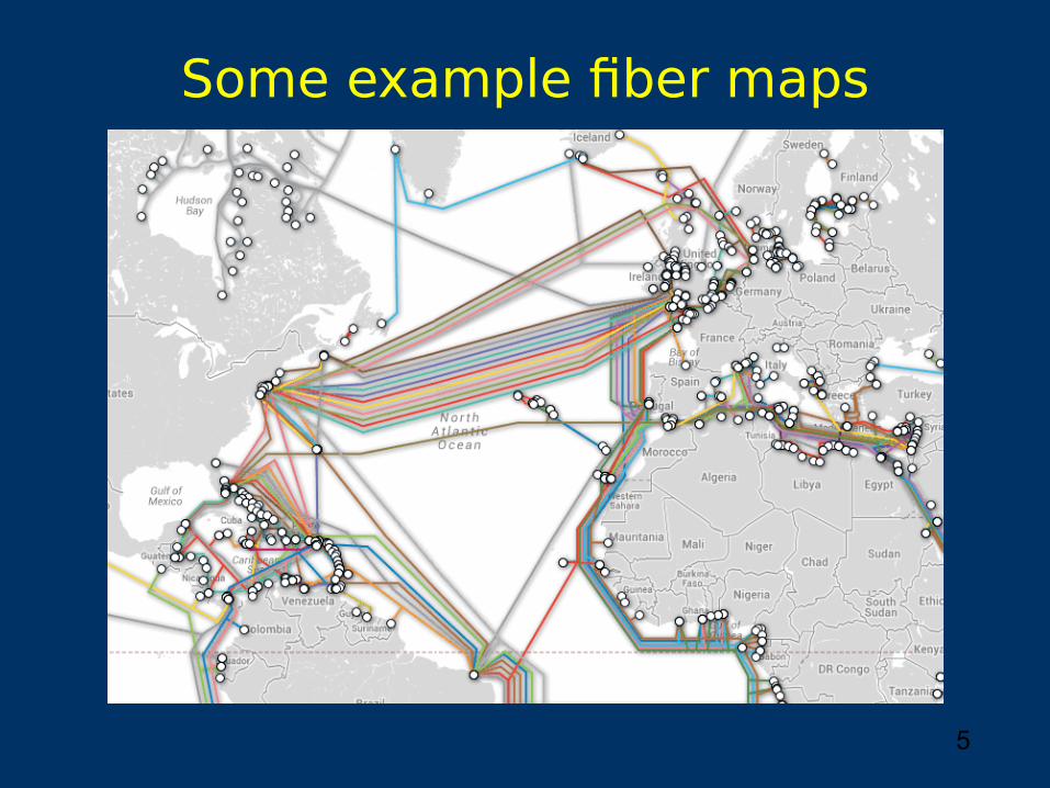
5
Some example fiber maps
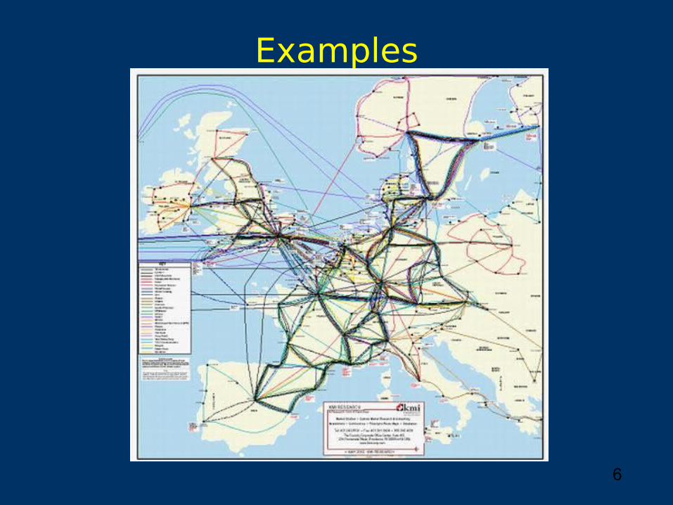
6
Examples
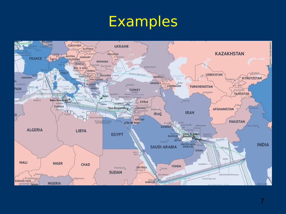
7
Examples
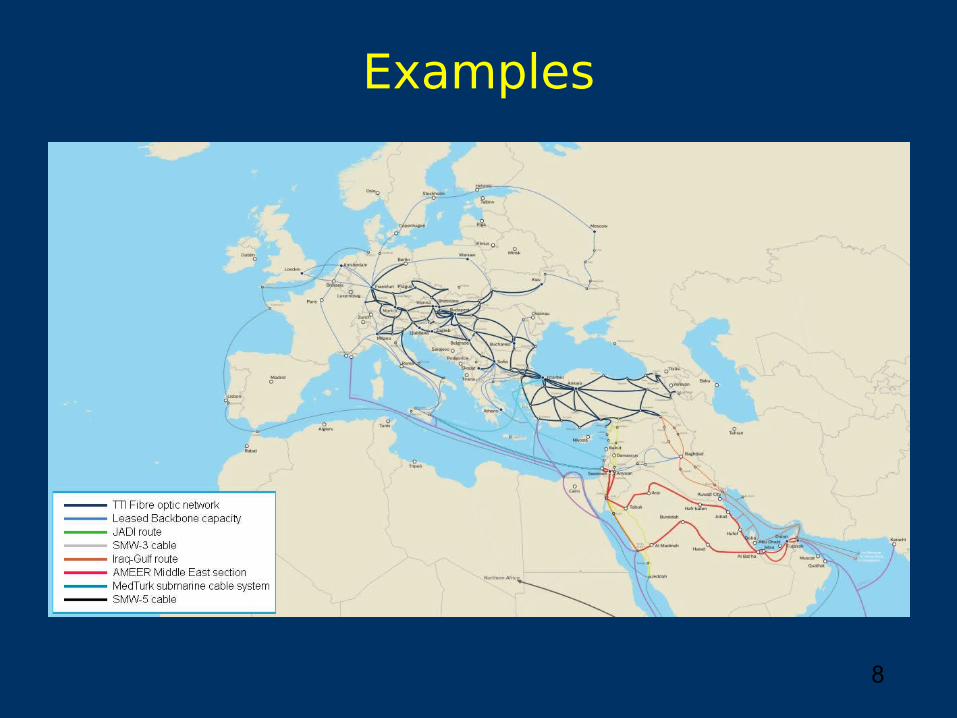
8
Examples
9
EDFA A key enabler of cost-effective WDM systems was the
development of the erbium-doped fiber amplifier (EDFA). Prior to the deployment of EDFAs, each wavelength on a
fiber had to be individually regenerated, at roughly 40 km intervals.
In contrast, EDFAs, deployed at roughly 80 km intervals, optically amplify all of the wavelengths on a fiber at once.
Early EDFA systems allowed optical signals to be transmitted on the order of 500 km before needing to be individually regenerated.
More recent EDFA systems allowed this distance to be increased to 1,500–2,500 km.
10
Increasing bit rate In the mid-1990s, the maximum bit rate of a
wavelength was roughly 2.5 Gb/s. This has since ramped up to 10, 40, 100 Gb/s. 400 Gb/s and 1Tb/s rates are likely to be
deployed in the 2015-2020 timeframe. Increased wavelength bit rate combined with a
greater number of wavelengths per fiber has expanded the capacity of optical networks by several orders of magnitude over a period of 25 years.
11
Optical bypass Optical-bypass technology eliminates much of the
required electronic processing. It allows a signal to remain in the optical domain for
all, or much, of its path from source to destination. Achieving optical bypass required advancements in
areas such as optical amplification, optical switching, transmission formats, and techniques to mitigate optical impairments.
Commercialization of optical bypass technology began in the mid-to-late 1990s.
12
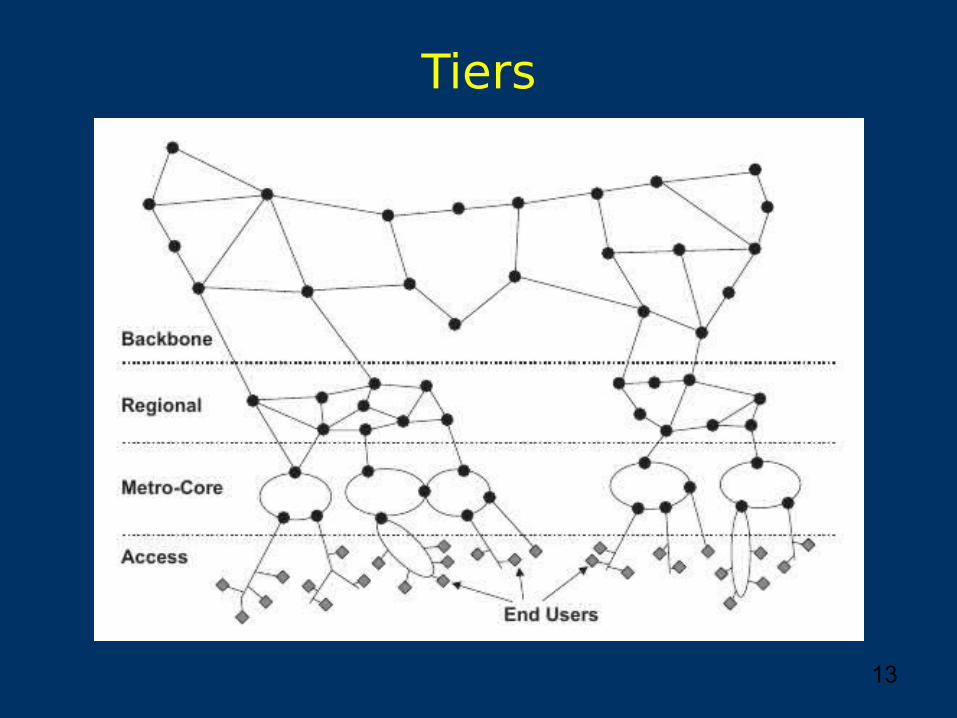
Tiers It is useful to segment the network into multiple
geographic tiers. Key differentiators among the tiers:
the number of customers served the required capacity, and the geographic extent.
13
Tiers
14
Access Tier At the edge of the network, closest to the end
users, is the access tier. It distributes/collects traffic to/from the customers of
the network. Access network generally serves tens to hundreds of
customers. It span a few kilometers. It can be subdivided into:
business access and residential access, or metro access and rural access.
15
Metro Tier The metro-core tier is responsible for
aggregating the traffic from the access networks. Typically interconnects a number of tele-
communications central offices or cable distribution head-end offices.
A metro-core network aggregates the traffic of thousands of customers.
It spans tens to hundreds of kilometers.
16
Core/Backbone Tier Moving up the hierarchy, multiple metro-core
networks are interconnected via regional networks. A regional network carries the portion of the traffic that
spans multiple metro-core areas, and is shared among hundreds of thousands of customers
A geographic extent of several hundred to a thousand kilometers.
Interregional traffic is carried by the backbone network. Backbone networks may be shared among millions of
customers. They typically span thousands of kilometers.
17
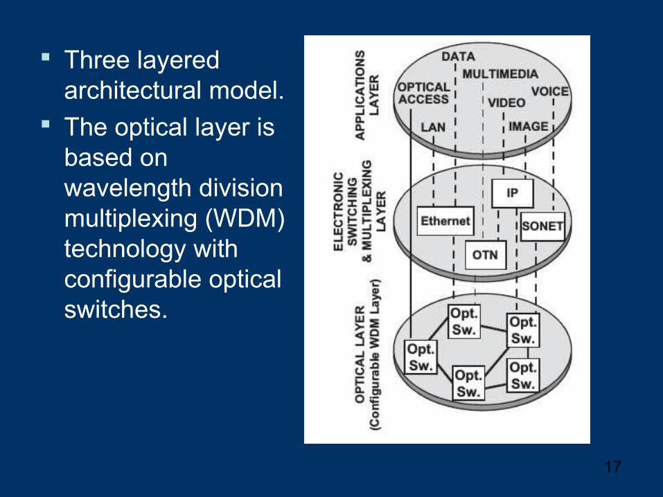
Three layered architectural model.
The optical layer is based on wavelength division multiplexing (WDM) technology with configurable optical switches.
18
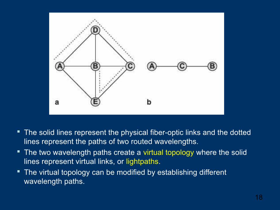
The solid lines represent the physical fiber-optic links and the dotted lines represent the paths of two routed wavelengths.
The two wavelength paths create a virtual topology where the solid lines represent virtual links, or lightpaths.
The virtual topology can be modified by establishing different wavelength paths.
19
TE vs. NE vs. NP Traffic Engineering:
“Put the traffic where the bandwidth is” Network Engineering:
“Put the bandwidth where the traffic is” Network Planning:
“Put the bandwidth where the traffic is forecasted to be”
20
Traffic Engineering Essentially a routing problem
packets, packet flows, circuits
on-line dynamic problem, quick decision making Metric: blocking probability
21
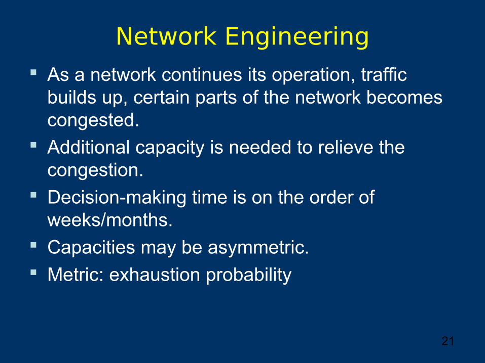
Network Engineering As a network continues its operation, traffic
builds up, certain parts of the network becomes congested.
Additional capacity is needed to relieve the congestion.
Decision-making time is on the order of weeks/months.
Capacities may be asymmetric. Metric: exhaustion probability
22
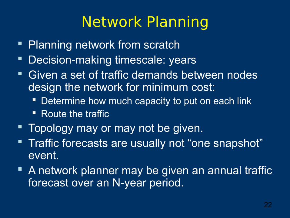
Network Planning Planning network from scratch Decision-making timescale: years Given a set of traffic demands between nodes
design the network for minimum cost: Determine how much capacity to put on each link Route the traffic
Topology may or may not be given. Traffic forecasts are usually not “one snapshot”
event. A network planner may be given an annual traffic
forecast over an N-year period.
23
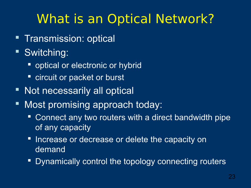
What is an Optical Network? Transmission: optical Switching:
optical or electronic or hybrid circuit or packet or burst
Not necessarily all optical Most promising approach today:
Connect any two routers with a direct bandwidth pipe of any capacity
Increase or decrease or delete the capacity on demand
Dynamically control the topology connecting routers
24
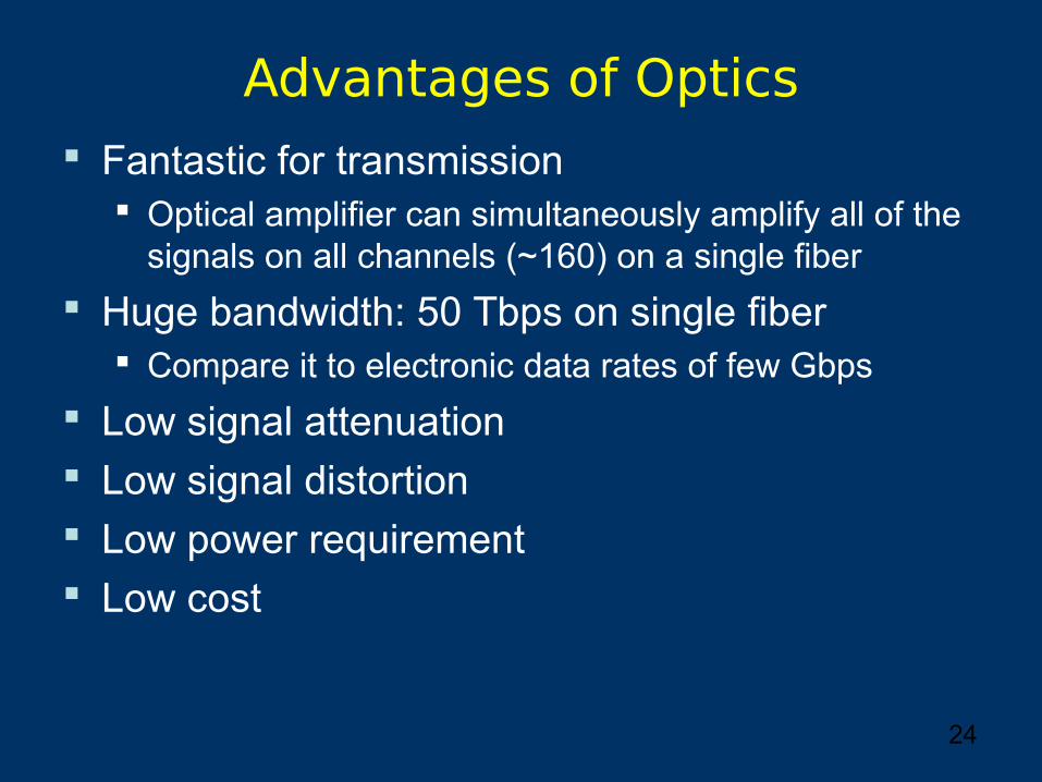
Advantages of Optics Fantastic for transmission
Optical amplifier can simultaneously amplify all of the signals on all channels (~160) on a single fiber
Huge bandwidth: 50 Tbps on single fiber Compare it to electronic data rates of few Gbps
Low signal attenuation Low signal distortion Low power requirement Low cost
25
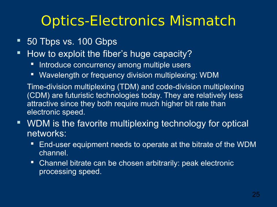
Optics-Electronics Mismatch 50 Tbps vs. 100 Gbps How to exploit the fiber’s huge capacity?
Introduce concurrency among multiple users Wavelength or frequency division multiplexing: WDM
Time-division multiplexing (TDM) and code-division multiplexing (CDM) are futuristic technologies today. They are relatively less attractive since they both require much higher bit rate than electronic speed.
WDM is the favorite multiplexing technology for optical networks: End-user equipment needs to operate at the bitrate of the WDM
channel. Channel bitrate can be chosen arbitrarily: peak electronic
processing speed.
26
WDM The optical transmission spectrum is carved up
into a number of non-overlapping wavelength bands.
Each wavelength supports a single communication channel operating at any electronic speed.
Challenge is to design and develop appropriate network architectures, protocols, and algorithms.
27
Research on Optical WDM Networks
Considerable activity over the past years. Check out the magazines and transactions: IEEE
Communications, IEEE Network, ToN, JSAC, JLT, Optical Networking Magazine, Jrn. Photonic Networks, …
Overwhelming attendance at the WDM centered conferences and workshops. ICC, Globecom, Infocom, OFC, ECOC, ONDM, …
Many experimental prototypes are being deployed and tested by telecom providers in US, Europe and Japan.
28
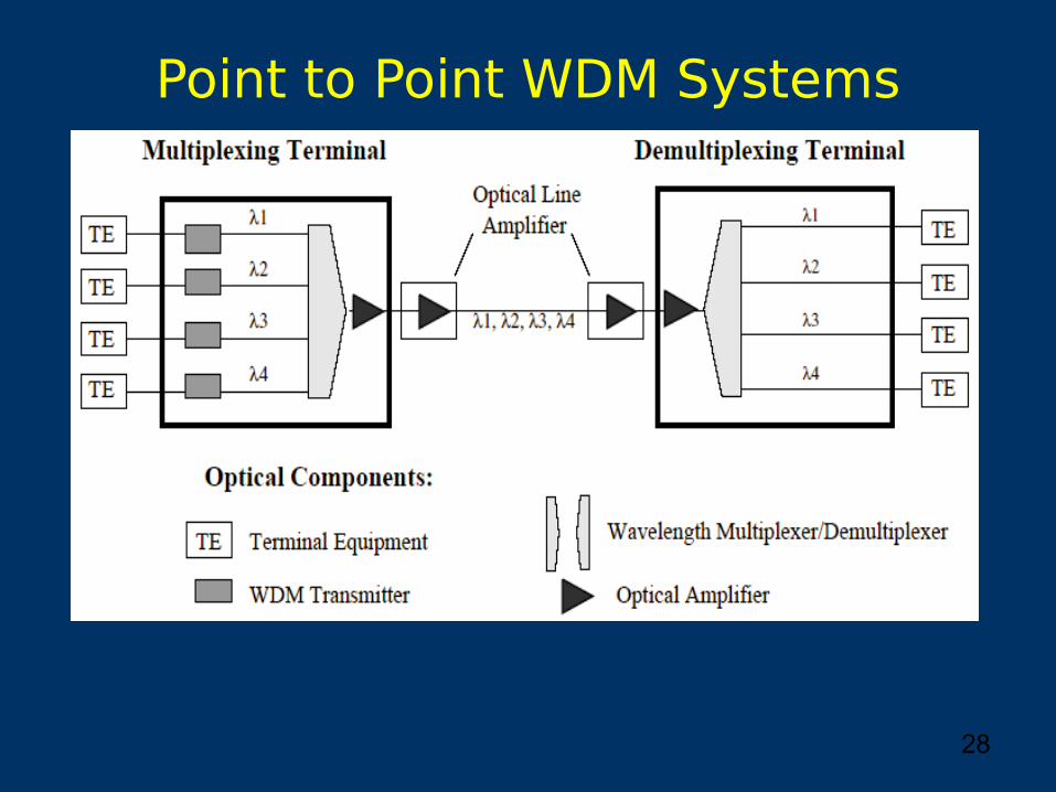
Point to Point WDM Systems
29
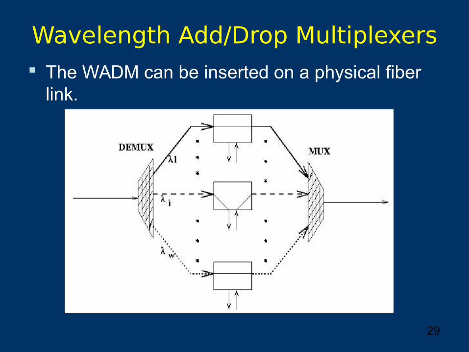
Wavelength Add/Drop Multiplexers The WADM can be inserted on a physical fiber
link.
30
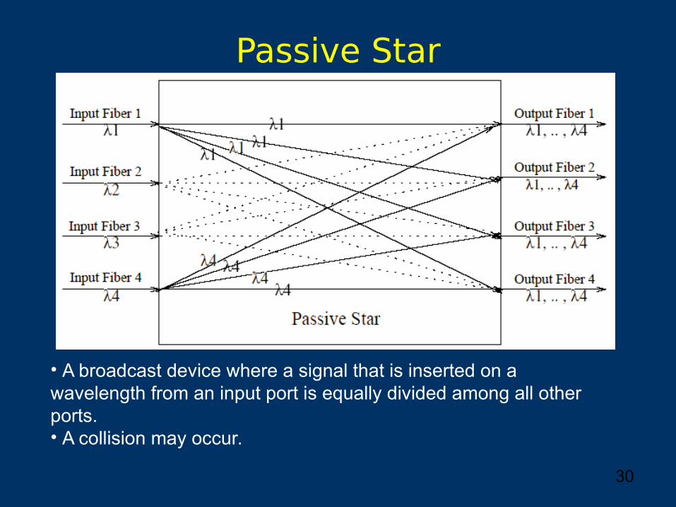
Passive Star
• A broadcast device where a signal that is inserted on a wavelength from an input port is equally divided among all other ports.• A collision may occur.
31
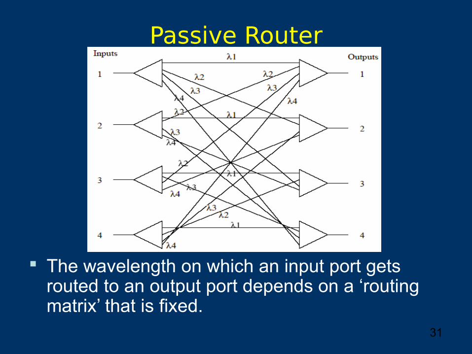
Passive Router
The wavelength on which an input port gets routed to an output port depends on a ‘routing matrix’ that is fixed.
32
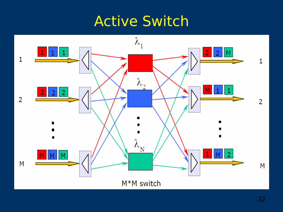
Active Switch