optical fiber _material science10
TRANSCRIPT
8/7/2019 Optical Fiber _material science10
http://slidepdf.com/reader/full/optical-fiber-material-science10 1/30
Optical Fiber

8/7/2019 Optical Fiber _material science10
http://slidepdf.com/reader/full/optical-fiber-material-science10 2/30
What is an optical fiber?
• Optical fibers are very fine fibers of glass.
• Usually glass “core” ---- size -----roughly 50 micrometres (diameter)
glass "cladding" ---- size ------ 120 micrometres (diameter).
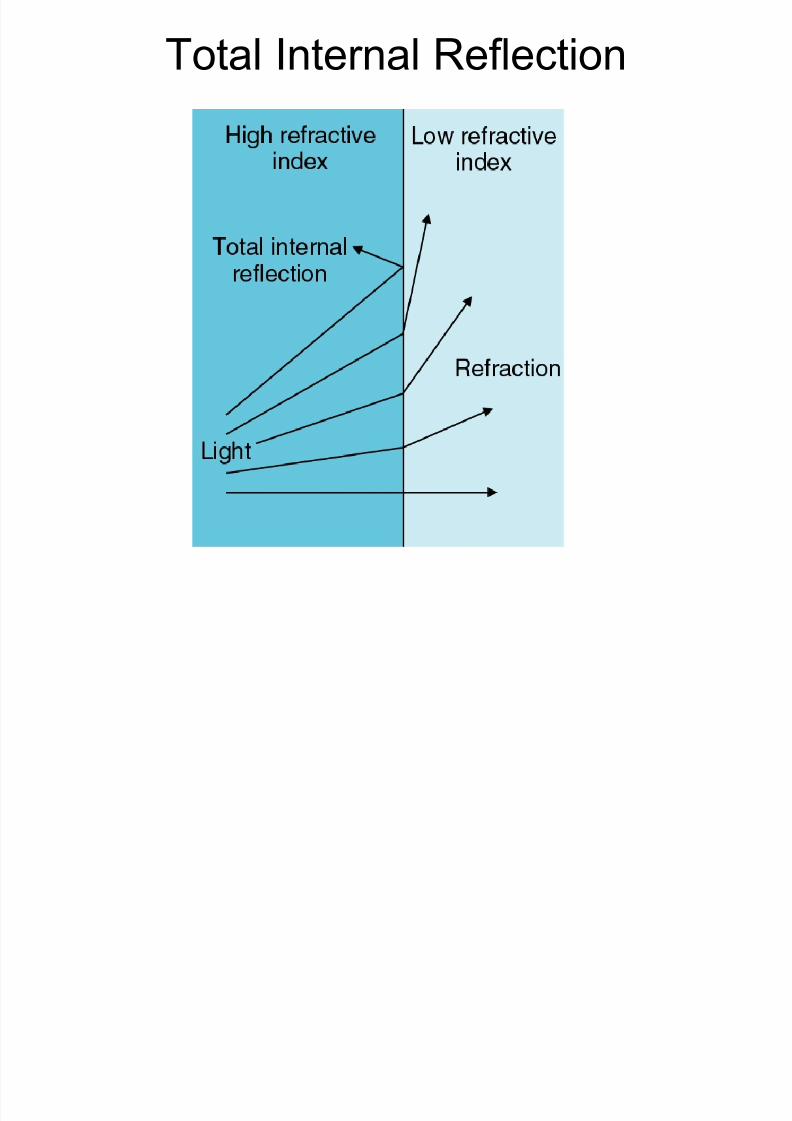
• They make use of total internal reflection to confine light within the
core of the fiber.

8/7/2019 Optical Fiber _material science10
http://slidepdf.com/reader/full/optical-fiber-material-science10 3/30
Structure of a Fibre
• The core has a higher refractive index than the cladding. --- TIR.
• The cladding is not just a mere covering but controls critical angle.
• Optical Fibres are optical waveguides. So optical fibres can beused to make light bend round corners
8/7/2019 Optical Fiber _material science10
http://slidepdf.com/reader/full/optical-fiber-material-science10 4/30
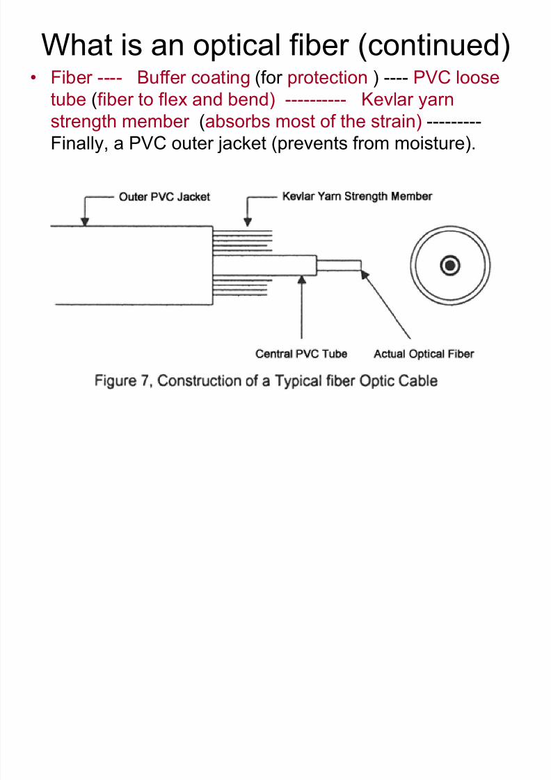
What is an optical fiber (continued)• Fiber ---- Buffer coating (for protection ) ---- PVC loose
tube (fiber to flex and bend) ---------- Kevlar yarn
strength member (absorbs most of the strain) ---------
Finally, a PVC outer jacket (prevents from moisture).
8/7/2019 Optical Fiber _material science10
http://slidepdf.com/reader/full/optical-fiber-material-science10 5/30
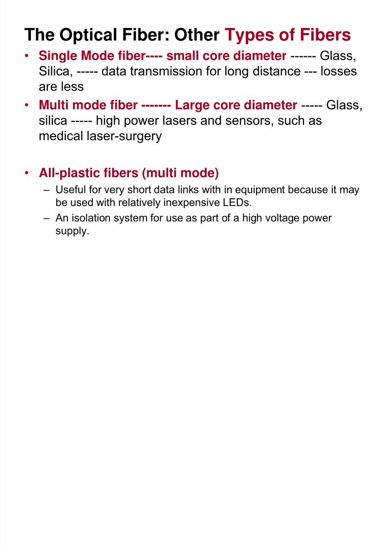
The Optical Fiber: Other Types of Fibers• Single Mode fiber---- small core diameter ------ Glass,
Silica, ----- data transmission for long distance --- losses
are less
• Multi mode fiber ------- Large core diameter ----- Glass,silica ----- high power lasers and sensors, such as
medical laser-surgery
• All-plastic fibers (multi mode)
– Useful for very short data links with in equipment because it may
be used with relatively inexpensive LEDs.– An isolation system for use as part of a high voltage power
supply.
8/7/2019 Optical Fiber _material science10
http://slidepdf.com/reader/full/optical-fiber-material-science10 6/30
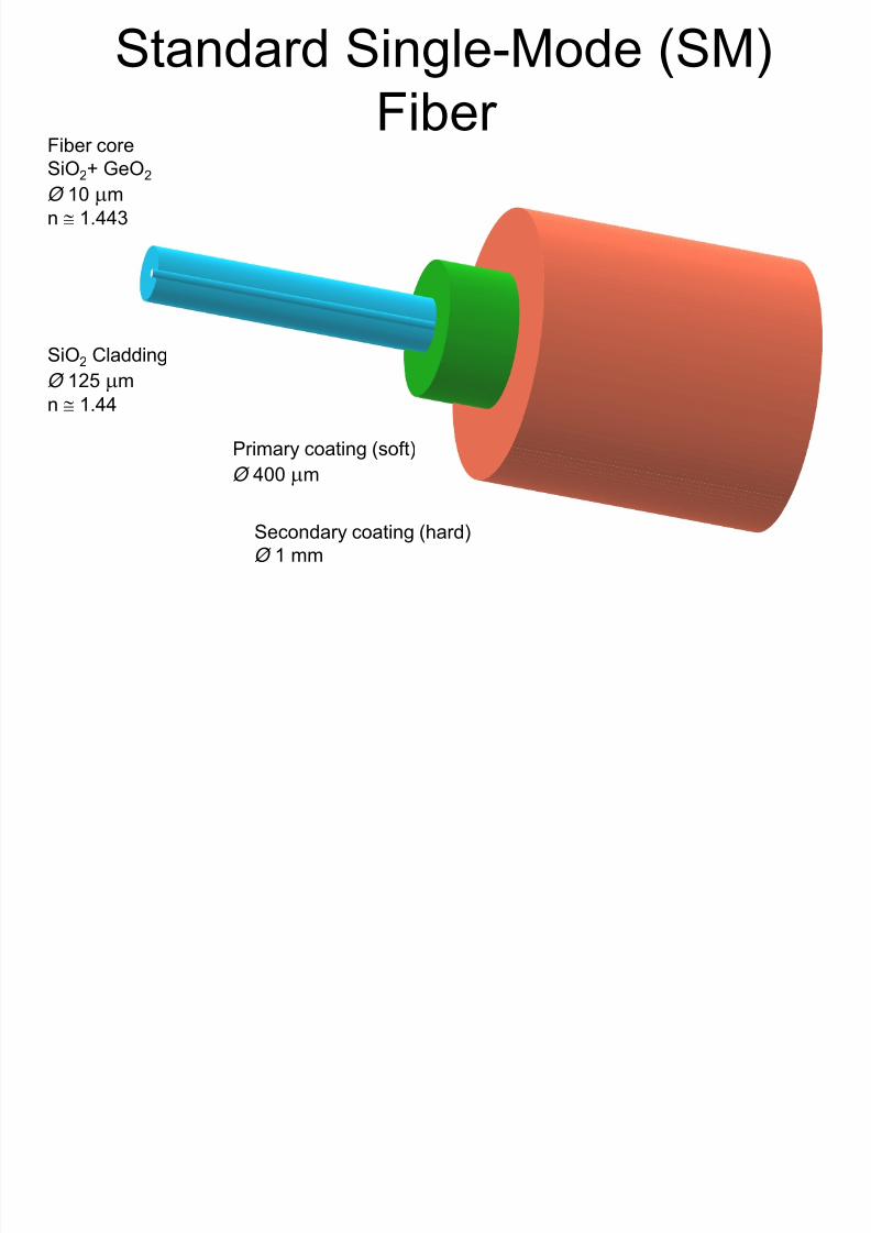
Standard Single-Mode (SM)
Fiber Fiber core
SiO2+ GeO2
Ø 10 μm
n ≅ 1.443
SiO2 Cladding
Ø 125 μm
n ≅ 1.44
Primary coating (soft)Ø 400 μm
Secondary coating (hard)
Ø 1 mm

8/7/2019 Optical Fiber _material science10
http://slidepdf.com/reader/full/optical-fiber-material-science10 7/30
Optical Fibers in brief
• An optical fiber consists of a high-index glasscore in a low-index glass sheath
• When light tries to leave the high-index core at
a shallow angle, it experiences total internalreflection
• Light bounces endlessly through the core and
emerges from the end of the fiber
• If the glass is pure and perfect enough, the
light may travel for many kilometers throughthe fiber

8/7/2019 Optical Fiber _material science10
http://slidepdf.com/reader/full/optical-fiber-material-science10 8/30
History of Fiber optics
During 1930, ideas were developed with this fiberoptic such as transmitting images through a fiber.
• During the 1960s, Lasers were introduced asefficient light sources
• In 1970s , All plastic fibers experienced excessive
optical loss. This motivated the scientists to developglass fibers.
• Applications such as medical environment to the
broadcasting industry. It is used to transmit voice,
television, images and data signals through small
flexible threads of glass or plastic.
8/7/2019 Optical Fiber _material science10
http://slidepdf.com/reader/full/optical-fiber-material-science10 9/30
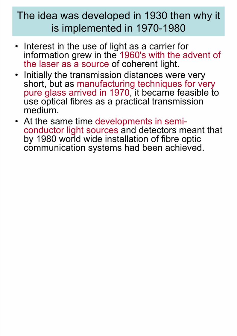
The idea was developed in 1930 then why it
is implemented in 1970-1980• Interest in the use of light as a carrier for
information grew in the 1960's with the advent of
the laser as a source of coherent light.• Initially the transmission distances were very
short, but as manufacturing techniques for very
pure glass arrived in 1970, it became feasible touse optical fibres as a practical transmissionmedium.
• At the same time developments in semi-conductor light sources and detectors meant thatby 1980 world wide installation of fibre opticcommunication systems had been achieved.
8/7/2019 Optical Fiber _material science10
http://slidepdf.com/reader/full/optical-fiber-material-science10 10/30
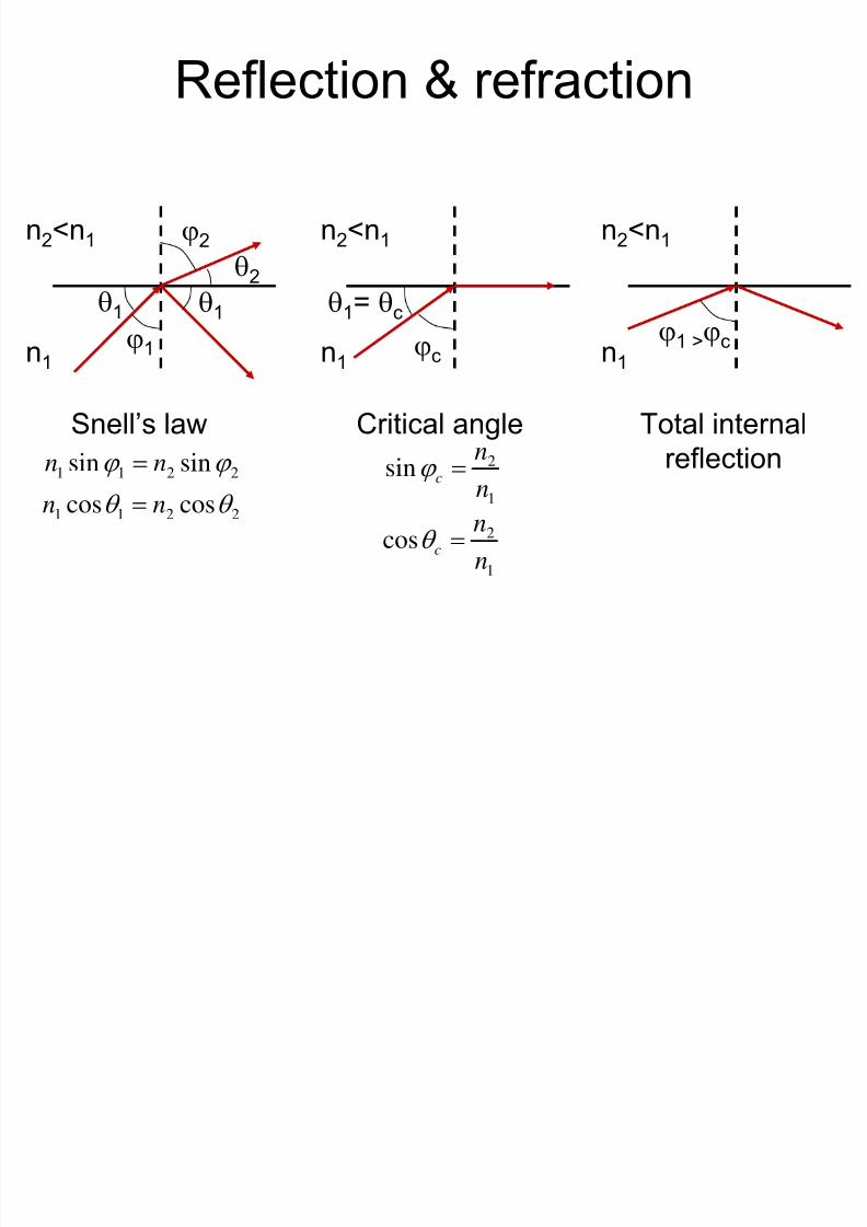
Reflection & refraction
n2<n1
n1
θ1 θ1
ϕ1
θ2
ϕ2
Snell’s law
2211 sinsin ϕ ϕ nn =
2211 coscos θ θ nn =
n2<n1
n1
θ1= θc
ϕc
Critical angle
1
2sinnn
c =ϕ
1
2cos
n
nc =θ
n2<n1
n1 ϕ1 >ϕc
Total internal
reflection
8/7/2019 Optical Fiber _material science10
http://slidepdf.com/reader/full/optical-fiber-material-science10 11/30
Total Internal Reflection
8/7/2019 Optical Fiber _material science10
http://slidepdf.com/reader/full/optical-fiber-material-science10 12/30
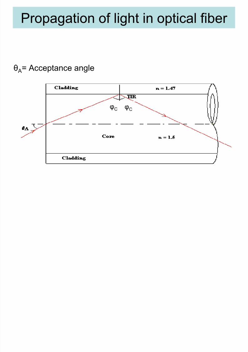
Propagation of light in optical fiber
θA= Acceptance angle
φC φC

8/7/2019 Optical Fiber _material science10
http://slidepdf.com/reader/full/optical-fiber-material-science10 13/30
Show that Numerical Aperture
1
2sinn
nc =ϕ Critical angle:
Maximum entrance angle:r A
n
nθ θ sinsin
0
1max, =
Multimode fiber
n1
n2
θA
n0
n0
2
2
2
1
2
111max,0 sin1cossinsin nnnnnnNA ccr A −=−===≡ ϕ ϕ θ θ
1
21
2
1
2
2
2
1
21
2
: if
n
nn
n
nn
nnn
−≈
−≡Δ
=≈Δ≈−= 2
2
2
2
1 nnnNA
°≈⇒= 61.0 max,ANAIf θ
φcθr
2
2
2
10 sin nnnNA A −== θ
Where ∆ is called fractional refractive index change

8/7/2019 Optical Fiber _material science10
http://slidepdf.com/reader/full/optical-fiber-material-science10 14/30
Modes & Rays
waveguide
d
θ2 θ1 θ0
m=0 m=2m=1
( )d
mk mx
π 1,
+= ⎟⎟⎠
⎞⎜⎜⎝
⎛ = −
0
,1sinnk
k mx
mθ

8/7/2019 Optical Fiber _material science10
http://slidepdf.com/reader/full/optical-fiber-material-science10 15/30
V-parameter
• V number: determines how many modes a
fiber supports
• Single-mode fiber:
( ) NAa
nna
V
λ
π
λ
π 22 2
2
2
1 =−=
405.2≤V
8/7/2019 Optical Fiber _material science10
http://slidepdf.com/reader/full/optical-fiber-material-science10 16/30
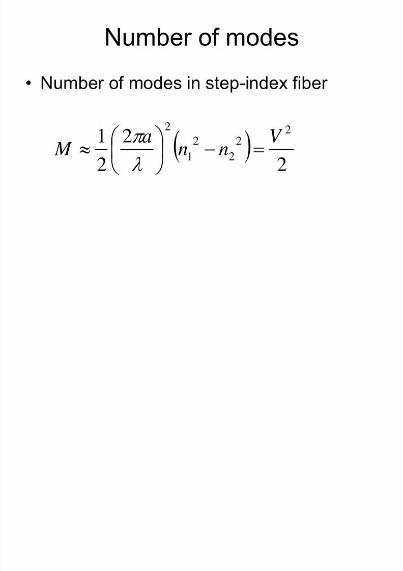
Number of modes
• Number of modes in step-index fiber
( ) 2
2
2
1 22
2
2
1
2V
nna
M =−⎟⎠
⎞
⎜⎝
⎛ ≈λ
π
8/7/2019 Optical Fiber _material science10
http://slidepdf.com/reader/full/optical-fiber-material-science10 17/30
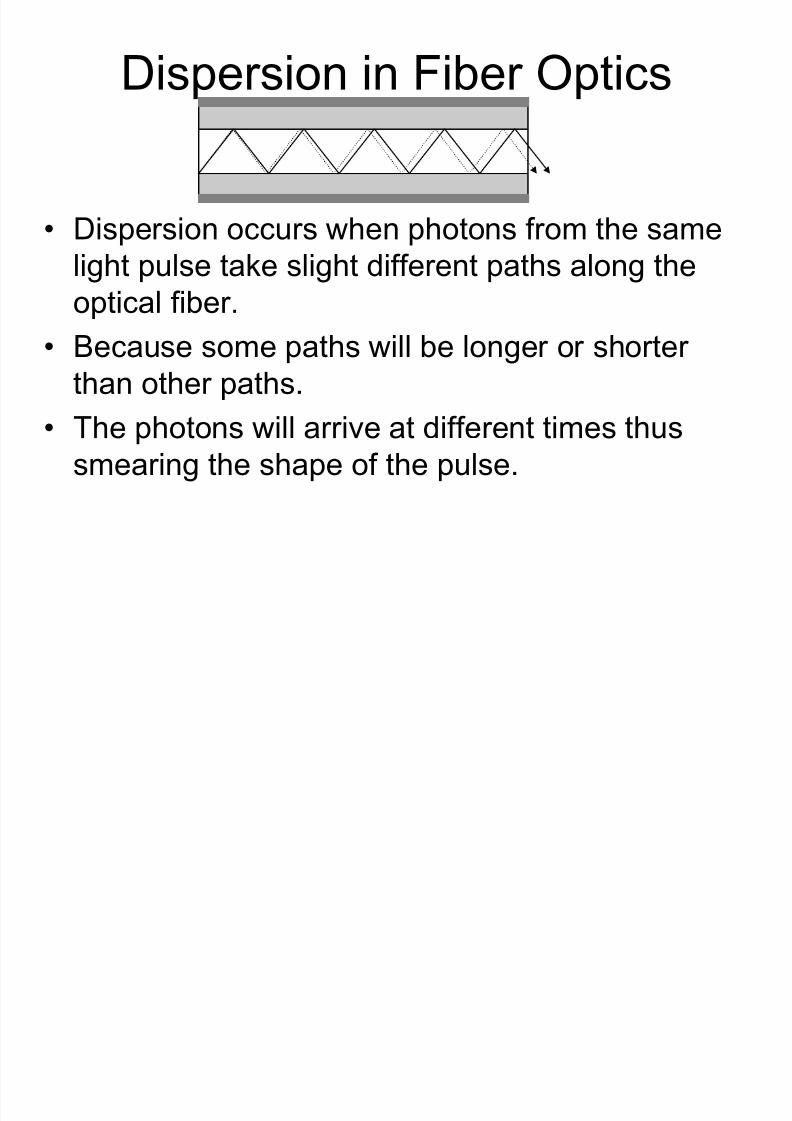
Dispersion in Fiber Optics
• Dispersion occurs when photons from the same
light pulse take slight different paths along the
optical fiber.• Because some paths will be longer or shorter
than other paths.
• The photons will arrive at different times thussmearing the shape of the pulse.
8/7/2019 Optical Fiber _material science10
http://slidepdf.com/reader/full/optical-fiber-material-science10 18/30
Dispersion Continued …
Normal fiber optic cable is called
multimode because photons can takedifferent paths along it.
The more expensivemonomode
fibre opticovercomes dispersion by having a core so
thin that the light can only take one path
along it.

8/7/2019 Optical Fiber _material science10
http://slidepdf.com/reader/full/optical-fiber-material-science10 19/30
8/7/2019 Optical Fiber _material science10
http://slidepdf.com/reader/full/optical-fiber-material-science10 20/30
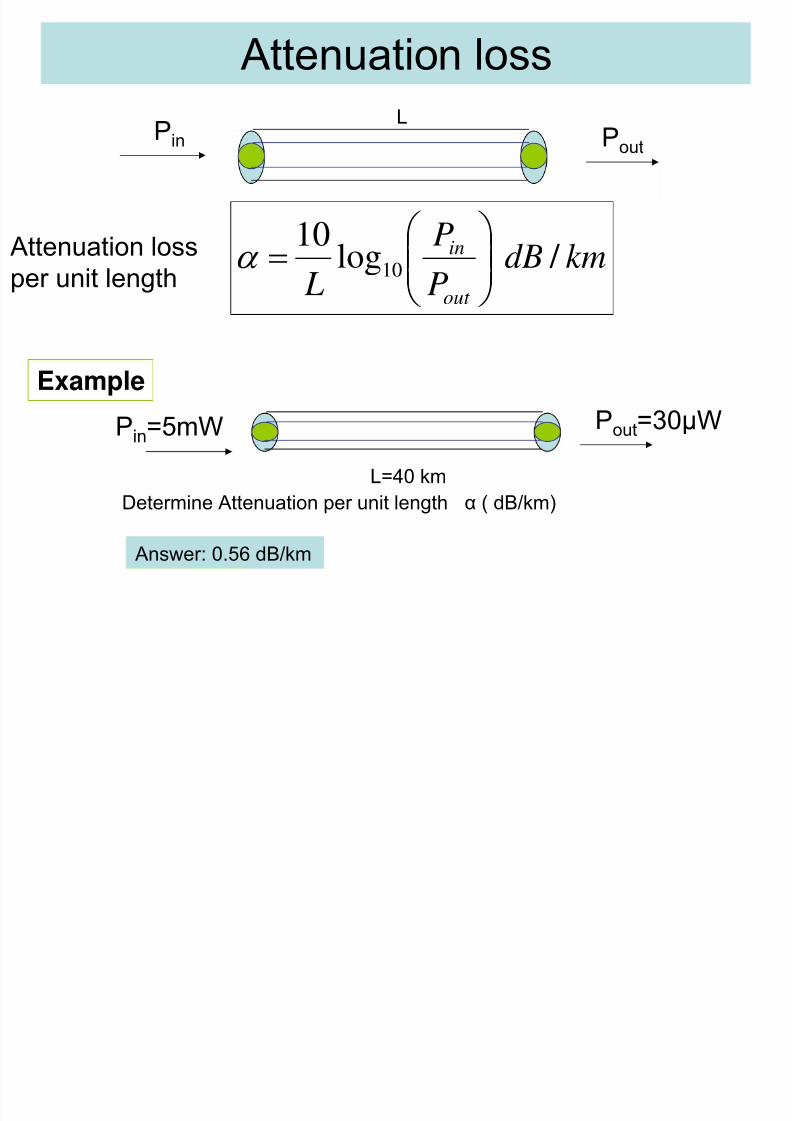
Attenuation loss
Pin Pout
kmdBP
P
L out
in / log10
10 ⎟⎟⎠
⎞⎜⎜⎝
⎛ =α
Example
Pin=5mW Pout=30µW
L=40 km
Determine Attenuation per unit length α ( dB/km)
Answer: 0.56 dB/km
Attenuation loss
per unit length
L

8/7/2019 Optical Fiber _material science10
http://slidepdf.com/reader/full/optical-fiber-material-science10 21/30
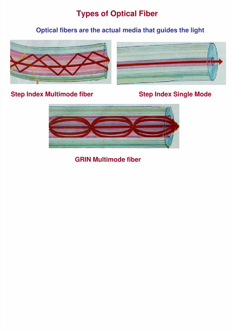
Types of Optical Fiber
• Glass fiber
– Step Index Fiber • Single mode (SM Fiber)
• Multimode (MM Fiber)
– Graded Index Fiber
• Plastic fiber
8/7/2019 Optical Fiber _material science10
http://slidepdf.com/reader/full/optical-fiber-material-science10 22/30
Step Index Single Mode
GRIN Multimode fiber
Step Index Multimode fiber
Types of Optical Fiber
Optical fibers are the actual media that guides the light
8/7/2019 Optical Fiber _material science10
http://slidepdf.com/reader/full/optical-fiber-material-science10 23/30
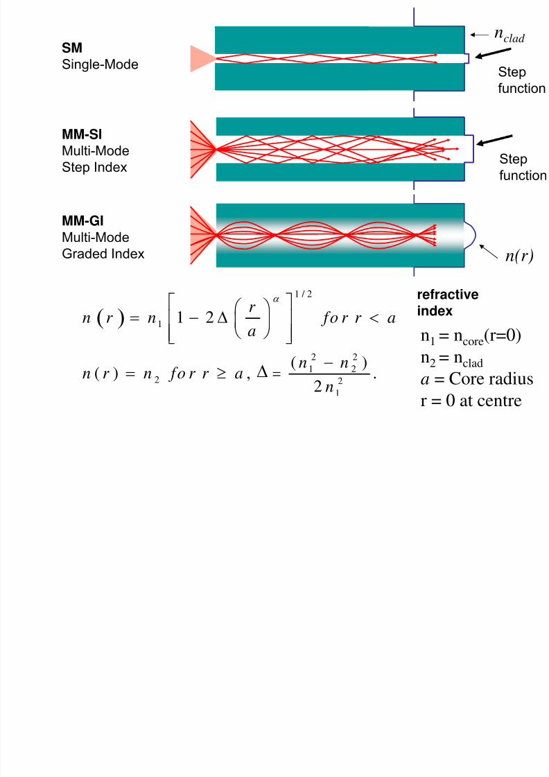
refractiveindex
SMSingle-Mode
MM-SI
Multi-ModeStep Index
MM-GIMulti-Mode
Graded Index
n1 = ncore(r=0)
n2 = nclada = Core radius
r = 0 at centre
Stepfunction
Step
function
nclad
n(r)
( )
1 / 2
1
2 2
1 22 2
1
1 2
( )( ) , .2
r n r n fo r r a
a
n nn r n fo r r an
α ⎡ ⎤⎛ ⎞= − Δ <⎢ ⎥⎜ ⎟⎝ ⎠⎢ ⎥⎣ ⎦
−= ≥ =∆
8/7/2019 Optical Fiber _material science10
http://slidepdf.com/reader/full/optical-fiber-material-science10 24/30
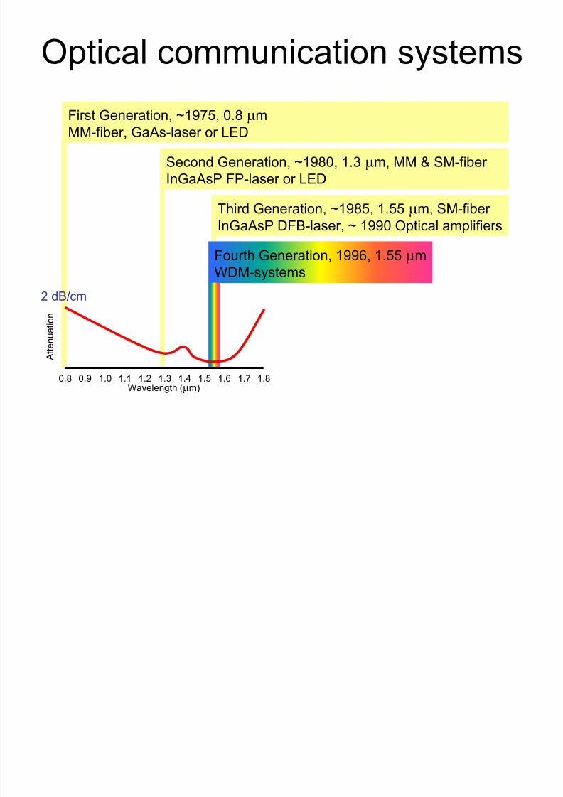
Optical communication systems
First Generation, ~1975, 0.8 μm
MM-fiber, GaAs-laser or LED
Second Generation, ~1980, 1.3 μm, MM & SM-fiber
InGaAsP FP-laser or LED
Third Generation, ~1985, 1.55 μm, SM-fiber
InGaAsP DFB-laser, ~ 1990 Optical amplifiers
Fourth Generation, 1996, 1.55 μm
WDM-systems
1.80.8 1.0 1.2 1.4 1.60.9 1.1 1.3 1.5 1.7Wavelength (μm)
At t e nu a t io n
2 dB/cm
Th d t f fib ti
8/7/2019 Optical Fiber _material science10
http://slidepdf.com/reader/full/optical-fiber-material-science10 25/30
The advantages of fiber optic over
wire cable
• Thinner
• Higher carrying capacity
• Less signal degradation
• Light signal
• Low power
• Flexible
• Non-flammable• Lightweight
Di d t f fib ti

8/7/2019 Optical Fiber _material science10
http://slidepdf.com/reader/full/optical-fiber-material-science10 26/30
Disadvantage of fiber optic over
copper wire cable• Optical fiber is more expensive per meter
than copper • Optical fiber can not be join together as
easily as copper cable. It requires trainingand expensive splicing and measurement
equipment.
8/7/2019 Optical Fiber _material science10
http://slidepdf.com/reader/full/optical-fiber-material-science10 27/30
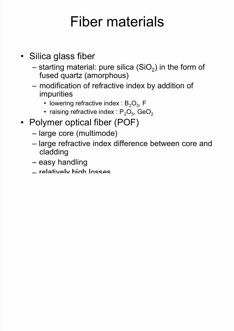
Fiber materials
• Silica glass fiber – starting material: pure silica (SiO2) in the form of
fused quartz (amorphous)
– modification of refractive index by addition of
impurities• lowering refractive index : B2O3, F
• raising refractive index : P2O5, GeO2
• Polymer optical fiber (POF)– large core (multimode)
– large refractive index difference between core and
cladding– easy handling
–
8/7/2019 Optical Fiber _material science10
http://slidepdf.com/reader/full/optical-fiber-material-science10 28/30
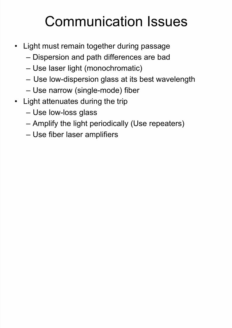
Communication Issues
• Light must remain together during passage
– Dispersion and path differences are bad
– Use laser light (monochromatic)
– Use low-dispersion glass at its best wavelength
– Use narrow (single-mode) fiber • Light attenuates during the trip
– Use low-loss glass
– Amplify the light periodically (Use repeaters)– Use fiber laser amplifiers
8/7/2019 Optical Fiber _material science10
http://slidepdf.com/reader/full/optical-fiber-material-science10 29/30
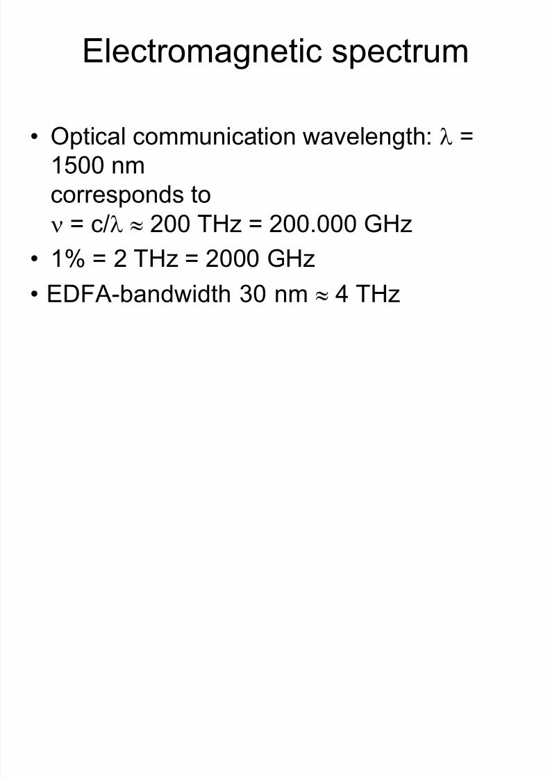
Electromagnetic spectrum
• Optical communication wavelength: λ =1500 nm
corresponds to
ν = c/λ ≈ 200 THz = 200.000 GHz
• 1% = 2 THz = 2000 GHz
• EDFA-bandwidth 30 nm ≈ 4 THz

8/7/2019 Optical Fiber _material science10
http://slidepdf.com/reader/full/optical-fiber-material-science10 30/30
1.80.8 1.0 1.2 1.4 1.60.9 1.1 1.3 1.5 1.7
Wavelength (μm)
At
tenuation (d
B/km)
0.2
0.5
1.0
1.5
0.16 dB/km
Rayleigh
scattering
IR band edge
OH--peak
UVabsorption
0.70.6
Fiber attenuation (SiO2)