optical coatings - tydex research&industrial optics · 16 domostroitelnaya str. 194292 st....
TRANSCRIPT

16 Domostroitelnaya str. 194292 St. Petersburg, Russia www.tydex.ru
Phone: 7-812-3318702 Fax: 7-812-3092958 E-mail: [email protected]
The Fresnel reflection at the boundary of media with different refractive indices and interference in thin films allow the optical components reflecting and transmitting properties to be selectively and controllably changed. The reflection from the surface of the optical part in the selected spectral range can be escalated or suppressed by applying special optical coatings. Additionally, the applied films can modify the physical properties of the optical component surface, for example, to increase its resistance to moisture and/or dust.
Tydex makes a wide range of optical coatings for our components from all processed materials. The spectrum is from near UV to far IR and millimeter range. The electron beam and resistive evaporation with ionic surface cleaning of parts and ion assisting are used at Balzers BAK-760 (Liechtenstein), VU-1AI and VU-2MI (Belarus) installations for depositing the optical coatings.
Our coatings are not limited to a standard set of designs. On the contrary, we try our best to satisfy the customer’s requirements. Please contact us and we will do our best to solve your problem as fully as possible.
I. METAL MIRRORS
Metal mirrors are used when high reflection in a wide spectral range is necessary. The reflectance of metal mirrors, unlike dielectric ones, does not depend very much on polarization the angle of incidence of light. The main disadvantages of metallic mirrors, in comparison with dielectric ones, are a slightly smaller reflection coefficient at given wavelengths and a significantly smaller radiation resistance.
1. Aluminum Mirrors
Aluminum mirrors remain the most commonly used metal mirrors due to its good reflection from UV to far IR and THz range, low cost and high resistance to external influences. Contacting with air, aluminum forms a layer of Al2O3 oxide a few nanometers thick. The layer is optically transparent, very dense and chemically stable. This layer provides the highest chemical resistance of aluminum film, but can not protect it from mechanical influences. If no such effects are expected on the mirror, an aluminum layer without protection can be used. Such mirrors are extremely useful, for example, inside scientific instruments, when the protective layer can be a source of undesirable interference or absorption.
But often additional protection of the reflective layer is required.
1.1. Protected Aluminum1.1.1. Aluminum mirrors with SiO2 and SiO protective coating are among the most commonly used. This coating is mechanically strong enough for most applications, but reduces a bit the reflection in the UV. In addition, it has some absorption by 3 μm (water) and by 9-11 μm (Si-O bond).
Wavelength, μm Average reflectance, % Damage threshold, J/cm2, 50 ns pulse
0.25-20.0 >90 0.25-0.3
1.1.2. As SiO2, and even more SiO, demonstrates high absorption at wavelengths shorter than 250 nm, such mirrors are bad in deep UV. For mirrors operating in the 200-250 nm range, it is preferable to use the MgF2 layer as a protection. It reduces the absorption loss in protection, but its mechanical strength is lower. Another important factor of losses in the GUF is scattering; for reducing it aluminum should be sprayed in a special way.
1.2. Enhanced AluminumInstead of a single-layer protection, it is possible to make a multilayer structure on the top of the aluminum film, which will slightly increase the reflection in the visible or near-IR range. Outside the «amplification» range, the reflection will be lower than that of bare aluminum. The damage threshold also remains at the level of unprotected aluminum.
Optical Coatings
Fig. 1.1. Reflection spectrum of an aluminum film with SiO2 protective coating.
Fig. 1. Reflection of an unprotected aluminum film.
Fig. 1.2.А. Reflection of “enhanced” aluminum.

16 Domostroitelnaya str. 194292 St. Petersburg, Russia www.tydex.ru
Phone: 7-812-3318702 Fax: 7-812-3092958 E-mail: [email protected]
Wavelength, μm Average reflectance, % Damage threshold, J/cm2, 50 ns pulse
0.4-0.7 >93 0.25-0.3
1.3. Metal-dielectric Mirrors
By increasing the number of dielectric layers on top of the aluminum film, reflection above 99% in the required spectral region can be achieved. A high-grade dielectric mirror is created on top of the aluminum film. The advantage of this design in comparison with the standard dielectric mirror is a high reflection in the entire spectral range and a lower sensitivity of the structure to a change in the angle of incidence and polarization of light. But the damage threshold of these structures remains low, for this reason they are not to be used in power optics.
2. Silver Mirrors
Silver mirrors differ from aluminum ones by a higher reflection in the visible and infrared ranges, but noticeably worse reflection in UV. Unlike Al2O3, silver oxide does not form a strong and stable film on the surface of silver and can not provide either mechanical or chemical protection of the metal. That is why the use of silver mirrors without a protective layer is almost impossible even when the mirror is protected from mechanical influences.
Fig. 1.2.В. Comparison of reflection of enhanced, standard and unprotected aluminum films.
Fig. 1.3. Reflection of a metal-dielectric mirror.
Wavelength, μm Average reflectance, % Damage threshold, J/cm2, 50 ns pulse
0.4-0.73-15
>95>98 0.25-0.3
2.1. Silver with Protection
Protecting the silver layer with a dielectric film makes the structure mechanically and chemically resistant.
Fig. 2.1. Reflection of a silver film with a protective coating.
Optical Coatings
2.2. “Sealed” Silver
Even the smallest pores in the protective film allow the silver to chemically interact with air, acid gases and water. The lifetime of silver mirrors can be significantly reduced by the heavy loads from the environment, such as high temperature and humidity, high industrial air pollution. The application of an additional protective layer in a special additional process allows to «seal» the pores in the protective film (also on the edges of the mirror) and significantly prolong the service life of the product. This can be especially important for equipment located in hard-to-reach places. Optically, this coating is virtually indistinguishable from standard p-silver.
3. Gold Mirrors
Gold mirrors are most often used in the infrared range. For light with wavelengths shorter than 600 nm, the reflection from gold is very low. Gold is chemically neutral, so even without a protective layer; it practically does not interact with atmospheric gases and water. This allows gold to be used without protection in scientific instruments, when interference or absorption lines in protective layers can be undesirable. But it should be remembered that the gold layer is extremely soft and can easily be damaged mechanically. For most applications, gold should be covered with an oxide protective structure.
Wavelength, μm Average reflectance, % Damage threshold, J/cm2, 50 ns pulse
0.6-20 >98 0.25-0.3
16 Domostroitelnaya str. 194292 St. Petersburg, Russia www.tydex.ru
Phone: 7-812-3318702 Fax: 7-812-3092958 E-mail: [email protected]
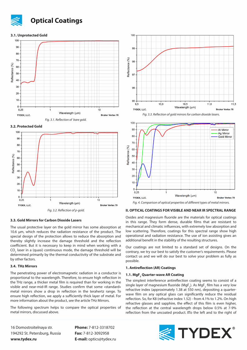
3.1. Unprotected Gold
3.2. Protected Gold
3.3. Gold Mirrors for Carbon Dioxide Lasers
The usual protective layer on the gold mirror has some absorption at 10.6 μm, which reduces the radiation resistance of the product. The special design of the protection allows to reduce the absorption and thereby slightly increase the damage threshold and the reflection coefficient. But it is necessary to keep in mind when working with a CO2 laser in a (quasi) continuous mode, the damage threshold will be determined primarily by the thermal conductivity of the substrate and by other factors.
3.4. THz Mirrors
The penetrating power of electromagnetic radiation in a conductor is proportional to the wavelength. Therefore, to ensure high reflection in the THz range, a thicker metal film is required than for working in the visible and near-mid-IR range. Studies confirm that some «standard» metal mirrors show a drop in reflection in the terahertz range. To ensure high reflection, we apply a sufficiently thick layer of metal. For more information about the product, see the article THz Mirrors.
The following spectrum helps to compare the optical properties of metal mirrors, discussed above.
Fig. 3.1. Reflection of bare gold.
Fig. 3.2. Reflection of p-gold.
Fig. 3.3. Reflection of gold mirrors for carbon dioxide lasers.
Optical Coatings
Fig. 4. Comparison of optical properties of different types of metal mirrors.
II. OPTICAL COATINGS FOR VISIBLE AND NEAR IR SPECTRAL RANGE
Oxides and magnesium fluoride are the materials for optical coatings in this range. They form dense, durable films that are resistant to mechanical and climatic influences, with extremely low absorption and low scattering. Therefore, coatings for this spectral range show high operational and radiation resistance. The use of ion assisting gives an additional benefit in the stability of the resulting structures.
Our coatings are not limited to a standard set of designs. On the contrary, we try our best to satisfy the customer’s requirements. Please contact us and we will do our best to solve your problem as fully as possible.
1. Antireflection (AR) Coatings
1.1. MgF2 Quarter-wave AR CoatingThe simplest interference antireflection coating seems to consist of a single layer of magnesium fluoride (MgF2). As MgF2 film has a very low refractive index (approximately 1.38 at 550 nm), depositing a quarter-wave film on any optical glass can significantly reduce the residual reflection. So, for K8 (refractive index 1.52) - from 4.1% to 1.2%. On high refractive glasses and sapphire, the effect of this film is even higher, the reflection at the central wavelength drops below 0.5% at 7-9% reflection from the uncoated product. ITo the left and to the right of
16 Domostroitelnaya str. 194292 St. Petersburg, Russia www.tydex.ru
Phone: 7-812-3318702 Fax: 7-812-3092958 E-mail: [email protected]
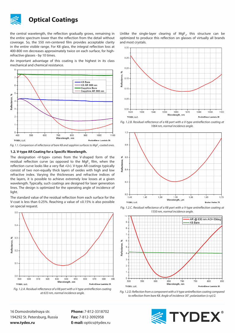
the central wavelength, the reflection gradually grows, remaining in the entire spectrum lower than the reflection from the detail without coverage. So, the 550 nm-centered film provides acceptable clarity in the entire visible range. For K8 glass, the integral reflection loss at 400-800 nm decreases approximately twice on each surface, for high-refractive glasses - by 10 times.
An important advantage of this coating is the highest in its class mechanical and chemical resistance.
1.2. V-type AR Coating for a Specific Wavelength.The designation «V-type» comes from the V-shaped form of the residual reflection curve (as opposed to the MgF2 film, when the reflection curve looks like a very flat «U»). V-type AR coatings typically consist of two non-equally thick layers of oxides with high and low refractive index. Varying the thicknesses and refractive indices of the layers, it is possible to achieve extremely low losses at a given wavelength. Typically, such coatings are designed for laser generation lines. The design is optimized for the operating angle of incidence of light.
The standard value of the residual reflection from each surface for the V-coat is less than 0.25%. Reaching a value of ≤0.15% is also possible on special request.
Fig. 1.1. Comparison of reflectance of bare K8 and sapphire surfaces to MgF2-coated ones.
Fig. 1.2.A. Residual reflectance of a K8 part with a V-type antireflection coating at 633 nm, normal incidence angle.
Optical Coatings
Unlike the single-layer clearing of MgF2, this structure can be optimized to produce this reflection on glasses of virtually all brands and most crystals.
Fig. 1.2.B. Residual reflectance of a K8 part with a V-type antireflection coating at 1064 nm, normal incidence angle.
Fig. 1.2.C. Residual reflectance of a K8 part with a V-type antireflection coating at 1550 nm, normal incidence angle.
Fig. 1.2.D. Reflection from a component with a V-type antireflection coating compared to reflection from bare K8. Angle of incidence 30°, polarization (s+p)/2.

16 Domostroitelnaya str. 194292 St. Petersburg, Russia www.tydex.ru
Phone: 7-812-3318702 Fax: 7-812-3092958 E-mail: [email protected]
1.3. Dual-band W-type AR Coatings
Two-way AR multilayer coatings are required when the optical components must provide very high transmittance at two different wavelengths. For example, when it is necessary to ensure that the fundamental wavelength of the laser generation and the second harmonic pass through the optical element. The presence of two «dips» in the spectrum of residual reflection of this coating makes it look like the letter W, which gives the name to this family of coatings. Structurally these coatings consist of 4 layers formed by three materials with different refractive indices.
1.4. Broadband Antireflection (BBAR) Coating
Low reflection in a wide spectral range is achieved by using the structures of three to six layers consisted usually of three or more materials with different refractive indices.
However, it should be remembered outside the narrow operating range the reflection from this structure will be higher than from the uncoated surface.
Fig. 1.3.А. Residual reflectance of a K8 surface with a W-type AR coating at 1064 and 532 nm, angle of incidence 0°.
Fig. 1.3.В. W-type AR coating for 532 and 1064 nm, angle of incidence 0°.
Optical Coatings
2. Highly Reflective Coatings
2.1. Dielectric Mirrors
High reflective (mirror) coatings consist of a sufficient number of pairs of equal-thickness layers of dielectric materials. The thickness of the layers and the number of pairs are determined on the basis of the condition for obtaining the required reflection at the central working wavelength and at the working angle of incidence. The width of the reflection zone is determined by the ratio of the refractive indices of the dielectrics used and is about 10-12% of the working wavelength. Such mirrors are created for working with lasers, when high reflection at one wavelength and high radiation resistance are required. Reflection from such structures in the working range exceeds 99% (typical for metals does not exceed 95%), and the radiation resistance is several Joules per cm2 (vs. 0.3 J/cm2 for metals). These coatings are usually designed for a 0 or 45 degree angle of incidence, but can be optimized for almost any other angle. For example, for our off-axis parabolic mirrors, dielectric designs are optimized for an operating angle of incidence equal to half the off-axis angle of the parabola.
Fig. 1.4.A. Residual reflectance of a TF-9 part with a broadband AR coating for 400-700 nm range, normal angle of incidence.
Fig. 1.4.B. Residual reflectance of a K8 part with a broadband AR coating for 1.2-2 μm range, angle of incidence 45°, (s+p)/2.

16 Domostroitelnaya str. 194292 St. Petersburg, Russia www.tydex.ru
Phone: 7-812-3318702 Fax: 7-812-3092958 E-mail: [email protected]
Fig. 2.1.A. Highly reflective dielectric mirror, 1064 nm, angle of incidence 0°.
Fig. 2.1.B. Dielectric mirror for 750-850 nm range, angle of incidence 22.5°. Residual transmitssion is shown. Polarization (s+p)/2.
Fig. 2.1.C. Dielectric mirror for 2.1 μm wavelength, angle of incidence 45°, (s+p)/2.
Optical Coatings
2.2. Dual-band Highly Reflective Coating
The design obtained as a result of successive deposition of two dielectric mirrors on the same substrate will have a high reflection at two wavelengths, although its radiation resistance will noticeably decrease. These mirrors are convenient to use when the system uses two lasers or a laser and its harmonic. A typical problem is channeling the sewage of the 1064-nm working beam and the 633-nm pilot imaging beam.
2.3. Broadband Highly-reflective Coatings
Sputtering on one substrate two dielectric mirrors centered on two close wavelengths, it is possible to obtain a product with a broad, even reflection spectrum. These coatings are in demand for working with tunable lasers (for example, Ti: Sa), especially at high angles of incidence, as well as for products that provide high reflection in a wide range of working angles.
Metal and metal-dielectric broadband highly-reflective coatings are used as well.
Fig. 2.2. Dual wavelength high-reflective mirror.
Fig. 2.3. Highly reflective “double” mirror for 700-900 nm range, angle of incidence 45°, (s+p)/2. Also shown the spectrum of the same mirror at normal incidence.

16 Domostroitelnaya str. 194292 St. Petersburg, Russia www.tydex.ru
Phone: 7-812-3318702 Fax: 7-812-3092958 E-mail: [email protected]
3. Beamsplitter Coatings
3.1. «Cold/Hot» Mirrors and Cut-off Filters
Besides the main reflection zone, the classical dielectric mirror has side maxima that are on the spectrum both to the left and to the right of the working wavelength.
By varying some layers of the «classical» packet, we can, without changing the reflection in the working spectral region, redistribute these side maxima, suppressing them either in the shortwave or in the long wave region. This way, it is possible to provide a sufficiently high transmission in the region to the left or right of the main mirror region. Depending on the side where the side peak was suppressed, these structures are called either cold or hot mirrors. «Hot» mirrors reflect infrared radiation, letting the visible. Such mirrors are used in projection systems to reduce the thermal load.
The same construction can be used to create a cutoff filter and protect a photodetector from unwanted radiation.
Fig. 3.1.А. Dielectric mirror and side peaks of reflection.
Fig. 3.1.В. A “cold” mirror. Reflection range 1.15-1.35 μm, S-pol, transmittance range 1.5-2.5 μm, P-pol. On KI quartz substrate, angle of incidence 45°.
Optical Coatings
Fig. 3.1.С. Cutoff filter. Transmission over 85% within 3.25-3.75 μm range (second side with AR coating). Transmission less than 0.1% below 2.5 μm. Germanium substrate.
A spectrum of bare germanium is provided for comparison.
3.2. Beamsplitting and Combining DesignThey are similar to «cold/hot» mirrors and allow to reduce the lasers beams at different wavelengths.
3.3. Polarization Splitters
At non-zero angles of incidence, S-polarized light is reflected much more effectively than P-polarized light. Also the high-reflection zone for P-polarized light gets narrower much faster than for S-polarized light. This effect allows creation of mirrors that strongly reflect S-polarized and transmit P-polarized radiation.
Fig. 3.3. Polarization splitter. High reflection at 2.05 μm, s-pol, high transmissivity at 2.2 μm, p-pol. Angle of incidence 50°.

16 Domostroitelnaya str. 194292 St. Petersburg, Russia www.tydex.ru
Phone: 7-812-3318702 Fax: 7-812-3092958 E-mail: [email protected]
3.4. Laser Output Mirrors
It is necessary to spray a sufficient number of film pairs with high and low refractive indices to get a dielectric totally reflector. With a smaller number of pairs, the reflection will be lower, but a part of the light will pass through the mirror. These designs practically do not absorb light, and the losses for scattering in them are minimal. Selecting the number of pairs, as well as the thickness and material of the last layer, one can achieve almost any ratio of transmission and reflection. These designs are ideally suited to work as output mirrors in laser cavities, removing the maximum possible power from the resonator and supporting a standing wave in it.
3.5. Broadband Semi-reflective (Beamsplitting) Coatings
Partially-reflective coatings for broadband applications are made in the same way. A typical application is a beam divider that directs part of the light from the object to the eyepiece, and the rest of the energy to the photodetector. Another example is the energy divider in the white light interferometer.
Fig. 3.4. Beam splitting coating R=(50 ±1)% at 1064 nm, angle of incidence 0° .
Fig. 3.5. Beam splitting coating for 1.5-3.5 μm range (s+p)/2, 45° AOI. KI quartz substrate.
Optical Coatings
3.6. THz Splitters
Dielectric mirrors can be used to solve the problem of separating the generated THz radiation and residual radiation from a Ti-sapphire pump laser. This mirror should consist of transparent materials in the THz range deposited on a substrate transparent in teraherts (usually silicon or crystalline quartz). Read more in the THz Spectral Splitters section.
III. IR COATINGS
Quarter-wave films used as IR coatings are 10 to 20 times thicker than those for visible region. Therefore, levels of stress and absorption, while negligible in the visible region, become limiting factors in the design of the IR coatings. Most oxides exhibit too high absorbance in the IR spectral region, and MgF2 produces films with exceeding levels of physical stress. Besides that IR substrates usually have high refraction indices. Therefore, high-performance film-forming materials are required to produce efficient interference structures. «Visible» materials can not be used as the main ones for the formation of optical IR coatings.
The main film-forming materials for the IR range are fluorides, chalcogenides and semiconductors. These materials tend to have significantly worse mechanical and climatic stability parameters than oxides and MgF2, as well as poorly tolerated ion assisting. To improve the performance of coatings, in many cases it is necessary to introduce additional functional layers and interlayers and to seek a compromise between strength, efficiency and damage threhold.
1. Simple IR Coatings
1.1. Single-layer Quarter-wave AR Coatings
The key advantage of quarter-wave films is the fact that even outside the zone of enlightenment they do not degrade the transmission of the part. The maximum bleaching is achieved when the refractive index of the bleached material and the film deposited are correctly matched. A classic film of magnesium fluoride, even if it could be applied with the required thickness for IR, would not provide an effective antireflection effect on IR substrates because of its too low refractive index. However, some analogs of a single layer can be made for the IR range. For example, a single-layer film of zinc sulphide on germanium is a sufficiently effective antireflection coating, and inferiority is the second only to a diamond-like coating.
Fig. 1.1.А. Reflection from silicon and germanium surfaces treated with ZnS film, as compared to reflection from bare surfaces.

16 Domostroitelnaya str. 194292 St. Petersburg, Russia www.tydex.ru
Phone: 7-812-3318702 Fax: 7-812-3092958 E-mail: [email protected]
Optical Coatings
One can see the refractive index of the film is nearly perfect for germanium, but somewhat too high for silicon. Lead fluoride has high spectral efficiency when used as a single-layer antireflection coating on silicon.
The film has nearly perfect refractive index for silicon. The reflection at the minimum does not exceed 0.5%. The film also has good anti-reflection properties on zinc selenide. Its refractive index is too low for germanium.
1.2. Waterproof Coating on Salts
A variant of a single-layer IR coating can be considered a protective coating on potassium bromide and other salt crystals (NaCl, KCl, etc.). Low refractive index of salts and their wide range of transparency make it practically impossible to improve their optical properties by film deposition. To protect optical components from salt crystals, an inorganic film is applied to their surface. This film is thin enough for all interference effects to remain in the short-wave inoperative region.
Fig. 1.1.В. ZnS film on silicon and germanium surfaces. Maximum antireflection efficiency zone.
Fig. 1.1.С. Reflection from zinc selenide, silicon and germanium surfaces coated with lead fluoride film.
Fig. 1.2. KBr window transmission bare and protected. The transmittance is margin-ally lower, no “organic” absorption bands are introduced.
1.3. V-type AR Coating for a Single Wavelength
Like their counterparts for the visible spectral range, V-type antireflection coatings are based on a design of two films with high and low refractive index. As for visible structures, varying the thicknesses and refractive indices of the layers, it is possible to optimize the design for a given substrate, the wavelength, and the angle of incidence of light. As in the «visible» case, the reflection from this structure outside the narrow operating range will be higher than from the surface without coverage. Usually these structures are used for clarification at laser wavelengths or at working wavelengths of gas analyzers.
1.4. AR Coating for Er:YAG @ 2.94 μm
A particular case of a V-type anti-reflection coating is coating for Er:YAG lasing @ 2.94 μm. This wavelength coincides with the peak of absorption of water, which is almost always present within the pores of oxide structures. By using hydrophobic IR materials, it is possible to produce a structure with lower absorption than a V-type oxide coating for the same wavelength.
Fig. 1.3. AR coating on zinc selenide at 10.6 μm (used with CO2 laser).

16 Domostroitelnaya str. 194292 St. Petersburg, Russia www.tydex.ru
Phone: 7-812-3318702 Fax: 7-812-3092958 E-mail: [email protected]
2. Broadband IR Coatings
2.1. Broadband AR Coating for 3-5 μm Range
One of the most widely used spectral ranges is the so-called “first atmospheric window” between 3 and 5 μm. It is sometimes narrowed to 3.7-4.8 μm. A lot of optical materials, such as silicon, zinc selenide, germanium, fluorite, sapphire and IR quartz are used at these wavelengths. For all these materials Tydex offers high-performance broadband coating, which has sufficient resistance to working outdoors under non-extreme conditions. Multilayer structures are used, containing no less than three materials with different refractive indices.
On silicon and germanium this coating can be combined with DLC on the front surface of the product. For more details refer to the article about DLC (Diamond-like Coating).
Fig. 1.4. AR coating at 2.94 μm on germanium, silicon and calcium fluoride.
Fig. 2.1.А. Broadband AR coating for the first atmospheric window applied to key IR materials.
Optical Coatings
Fig. 2.1.В. Transmission of a silicon window. Diamond-like coating on the front side, broadband AR coating on the back side.
2.2. Broadband AR Coating for 7-14 μm Range
In the second atmospheric window, 7-14 microns, germanium and zinc selenide are used as a material for manufacturing optics. In some cases silicon can be used. For this range we propose constructively the same design of AR coatings as for 3-5 μm, but the thickness of the interference layers becomes approximately 2.5 times larger. It makes the coatings somewhat less resistant and requiring for more accurate handling. Higher performance parameters can be achieved by dropping some of the spectral efficiency. After 11 μm the substrates and the sputtered structures show appreciable absorption.
Fig. 2.2.A. Residual reflection of Ge plate with two-side AR coating for 7-14 μm range.

16 Domostroitelnaya str. 194292 St. Petersburg, Russia www.tydex.ru
Phone: 7-812-3318702 Fax: 7-812-3092958 E-mail: [email protected]
Fig. 2.2.B. Transmitssion of Ge plate with two-side AR coating for 7-14 μm range.
Fig. 2.2.C. Residual reflection of ZnSe plate with two-side AR coating for 7-14 μm range.
Fig. 2.2.D. Transmission of ZnSe plate with two-side AR coating for 7-14 μm range.
Optical Coatings
Similarly to the case of the first atmospheric window, when used on silicon and germanium, this coating can be combined with DLC on the front side of the component.
Fig. 2.2.E. Transmission of Ge plate with DLC on the front side, 7-14 μm AR coating on the back side.
2.3. Broadband AR Coating for 3-5 + 8-12 μm Range
In some cases both infrared bands are channeled by a common optical system. For these cases we offer enlightenment in both ranges. Since it is impossible to clear both these channels simultaneously by a single layer, the use of resistant DLC or ZnS for the front surface is excluded. We have developed and manufactured wide-band illumination for both ranges for germanium substrates, which has an acceptable resistance to outdoor operation under non-extreme conditions.
Fig. 2.3. 3-5 and 8-12 μm antireflection coating on germanium.

16 Domostroitelnaya str. 194292 St. Petersburg, Russia www.tydex.ru
Phone: 7-812-3318702 Fax: 7-812-3092958 E-mail: [email protected]
Fig. 2.3.А. 3-5 and 8-12 μm antireflection coating for zinc selenide.
3. Super Broadband IR Coatings
3.1. Broadband AR Coating for 1.6-15 μm Range
Optical components of Fourier spectrometers must provide the widest possible transparency range. The most widely used material for such components, besides salts, is zinc selenide. We have developed and regularly produced an antireflection coating for this material which improves the transmission of products in the range from 1.6 to 15 μm.
Fig. 3.1. Transmission of a ZnSe window with two-side broadband ARcoating for 1.6-15 μm range.
If it is desirable for the customer to attenuate the visible and near-IR radiation to eliminate unwanted light, we offer a «dark» AR coating, effectively suppressing the undesirable range.
Optical Coatings
Fig. 3.1.А. Visible and near IR transmission of a “dark” AR Coating for 1.6-14 μm range.
3.2. Super Broadband ar coating for Germanium and 2.5-25 μm Range
Elements of high refractive materials are needed for ATR spectroscopy . The Fresnel losses at the input to such an ATR element and at the output from it substantially weaken the signal. There is a need to reduce the Fresnel losses in the widest possible spectral range. We have developed and produced this an AR coating for germanium ATR probes.
Fig. 3.2. Transmission of a Ge probe with AR coating as compared to a bare component.
4. IR Mirrors4.1. IR MirrorsBasically IR mirrors are arranged in the same way as oxide ones. They consist of alternating quarter-wave layers of materials with high and low refractive indices. The high contrast of refractive indices of IR materials allows to spray relatively broadband mirrors with a smaller number of pairs of layers in comparison with «visible» structures. The large thickness of the layers and the specificity of IR materials impose certain limitations on the design of the coatings. These mirrors are much thicker than the oxide structures for the visible range, and they have somewhat larger scattering at a substantially lower radiation resistance. Their main application is the separation or combination of spectral ranges, rather than the channeling of high-energy laser beams.

16 Domostroitelnaya str. 194292 St. Petersburg, Russia www.tydex.ru
Phone: 7-812-3318702 Fax: 7-812-3092958 E-mail: [email protected]
Fig. 4.1.А. Interference mirror for 2.1-3.3 μm range on ZnSe substrate.
Fig. 4.1.В. Interference mirror for 7-11 μm range on Si substrate, angle of incidence 45°. The mirror is transparent in THz range.
4.2. THz-10600
Dielectric IR mirrors can be used to solve the problem of separating the generated THz radiation and the residual radiation from the CO2 pump laser: the mirror should consist of transparent materials in the THz range deposited on a substrate transparent in teraherts (usually silicon or crystalline quartz). For more details please refer to the THz Spectral Splitters section.
4.3. Solar-blind Coatings
Another important application of interference IR mirrors is NIR cutoff. This problem arises, for example, when producing pyrgeometers - instruments for measuring the temperature of the earth’s surface. For conducting correct measurements it is necessary to cut out direct sunlight from the thermal radiation of the earth’s surface. Sunlight is energetically concentrated mainly in the range 0.2 - 5 microns. For the reradiated energy, the intensity peak is in the region of 15 μm (depending on the temperature), and it is important to pass the radiation to 45-50 μm. The exact cut-off wavelength can vary somewhat depending on the design features and the use of the finished product. It is selected in the range 4.5-5.5 μm. A family of the coatings, cutting light to the left of 5 microns and passing through 5-45 microns, was called the solar blind (filter-cutting) filters.
Optical Coatings
Similarly to usual “cold” dielectric mirrors, a solar blind coating is designed as an interference mirror with several additional layers enhancing its spectral characteristics in the long-wavelength area. Most of the film-forming IR materials show significant absorption above 12-15 μm. To ensure high transmission in the long-wave zone up to 45 μm, only suitable materials should be used in the design.
Fig. 4.3. Transmission of Si sample with a single-side Solar Blind coating and two-side Solar Blind + DLC coatings.
These filter coatings are widely used in pyrgeometers, instruments that measure effective radiation of the earth’s surface.
Our meniscal lenses with solar blind coating have been successfully tested as a part of a pyrgeometer by the Physical-meteorological observatory at Davos, Switzerland.
5. Beam SplittersAn interference structure can be used to increase the reflection of a surface in a wide spectral range while retaining partial transparency in the same range, i. e. to split the light beam between reflection and transmission. We have mastered the production of such parts based on semi-reflecting non-metallic interference structures.
6. Beam Splitter Coatings for FourierThe dividers for the Fourier spectrometers should not only divide the IR spectrum, but also have a division zone of the calibration laser, as a rule, it is tipically 633 nm. For more detailed information please refer to the article Substrates for the FTIR Beam Splitters.
Fig. 5. 50/50 beam splitter on a barium fluoride substrate.

16 Domostroitelnaya str. 194292 St. Petersburg, Russia www.tydex.ru
Phone: 7-812-3318702 Fax: 7-812-3092958 E-mail: [email protected]
Fig. 6.А. An example of a splitter coating on ZnSe substrate. Angle of incidence 45°.
Fig. 6.В. An example of a splitter coating on KBr substrate. Angle of incidence 30°.
Optical Coatings
IV. DIAMOND-LIKE OR HARD CARBON COATING
Diamond-like coating (DLC) or Hard Carbon Coating seems to be the most robust of all optical coatings. It is extremely resistant to salts, acids, alkalis, and most organic solvents. High mechanical hardness and low coefficient of friction make this film extremely resistant to abrasion. DLC has very good adhesion to germanium and silicon.
This coating is more often used on the outer surfaces of silicon and germanium optics of thermal imagers used in military equipment and/or operating under extreme climatic conditions. DLC protects external optical surfaces from the abrasive action of dust particles in the air, from sea water and salt, from engine oil and fuel, high humidity, improper handling etc.
The film is characterized by moderate absorption and scattering levels throughout the entire IR spectral range. Index of refraction of the diamond-like film in the IR is about 1.95. That’s why DLC film applied by special methods, combines outstanding protective properties with a good antireflection effect.
Being a single-layer coating, it can be optimized for a specific wavelength range (usually 3-5 or 8-14 μm bands) by adjusting layer thickness.
Fig. 1. Transmission of germanium parts with two-side DLC and DLC-BBAR. 1 mm thickness.
Fig. 2. Reflection of a DLC-coated germanium part.
Fig. 3. Transmission of silicon parts with two-side DLC and DLC-BBAR.

16 Domostroitelnaya str. 194292 St. Petersburg, Russia www.tydex.ru
Phone: 7-812-3318702 Fax: 7-812-3092958 E-mail: [email protected]
Fig. 4. Reflection of a DLC silicon part.
Optical Coatings
Specification
Chemical Properties
Composition carbon, hydrogen
Structure A composite of sp3-hybridized (tetragonal diamond-like lattice), sp2-hybridized (trigonal graphite-like lattice) and amorphous carbon
Reactivity Inert to acids, alkalis, solvents, salts, wa-ter and other reagents at ambient tem-perature. Combusts above 400°C.
Physical Properties
Density 1.8-2.1 г/сm3
Specific thermal conductivity 10 W/сm × K
Thermal expansion coefficient 9 × 10⁻⁶/°C
Resistivity Several MOhm × cm
Dielectric constant ~ 4-11
Permeability Impenetrable to hydrogen and other gases
Optical Properties
Optical transparency Near to middle IR
Refractive index 1.85 - 2.0
Other Properties
Operating temperature range from -60°C to +400°C
Biological compatibility Does not cause cellular breakdown or inflammation
Durability Good adhesion to substrate, resistant to hard abrasion and mechanical impacts, high humidity, high and low temperatures, heat shock, saline vapors, saline solutions, insoluble in water, resistant to atmospheric condensation, dust and sand, some acids, lube and fuel oils per standards: MIL-C-675C, MIL-STD-810
V. THz COATINGS
1. Parylene AR Coating for THz Range
The technology of vacuum synthesis of a parylene film on the surface of electronic boards and assemblies is well known. The resulting film protects the electronics from moisture and pollution.
According to our instructions, on the basis of «microelectronic» technology, a special aparatus has been developed that makes it possible to synthesize a parylene film of a given thickness with the highest uniformity on optical surfaces of arbitrary geometry.
The film has a refractive index of about 1.64 in the far IR and terahertz ranges. Its absorption and scattering in these spectral regions are negligible, the absorption bands are localized in the near and middle IR.
This film provides a significant increase in transmission (reduction of reflection) of THz optics made of high-resistance silicon, crystalline quartz and sapphire. It is possible to apply quarter-wave single-layer antireflection coatings to different ranges from 45 μm to 2000 μm.
Fig. 1. Transmition of a parylene film. Absorption bands are localized between 3.4-22 μm. Film thickness 14 μm.
Fig. 2. Crystalline quartz window with two-side parylene AR coating centered at 158 μm.
16 Domostroitelnaya str. 194292 St. Petersburg, Russia www.tydex.ru
Phone: 7-812-3318702 Fax: 7-812-3092958 E-mail: [email protected]
Optical Coatings
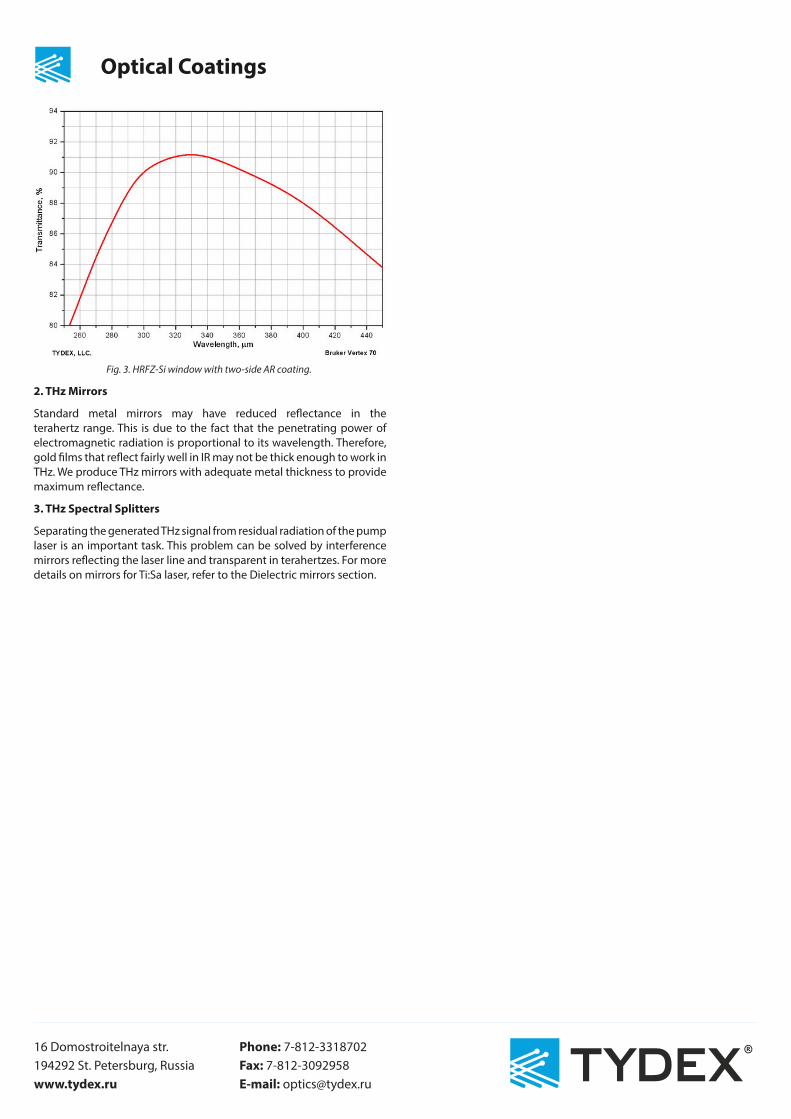
Fig. 3. HRFZ-Si window with two-side AR coating.
2. THz Mirrors
Standard metal mirrors may have reduced reflectance in the terahertz range. This is due to the fact that the penetrating power of electromagnetic radiation is proportional to its wavelength. Therefore, gold films that reflect fairly well in IR may not be thick enough to work in THz. We produce THz mirrors with adequate metal thickness to provide maximum reflectance.
3. THz Spectral Splitters
Separating the generated THz signal from residual radiation of the pump laser is an important task. This problem can be solved by interference mirrors reflecting the laser line and transparent in terahertzes. For more details on mirrors for Ti:Sa laser, refer to the Dielectric mirrors section.