optical burst switching - unimoremcasoni/tecnologie/obs_noe.pdf · aggregation function can...
TRANSCRIPT

Optical Burst SwitchingA tutorial from E-photon/ONe
The VD1 OBS taskforceSpeaker: Prof. Maurizio Casoni

2 e-photon/ONE WP7
Contributors
Universidad Pública de Navarra : D. Morato, M. Izal, E. Magaña and J. Aracil
DEIS-UniBo: Carla Raffaelli, Maurizio Casoni (Department ofInformation Engineering, University of Modena and Reggio Emilia)
Telenor/NTNU: Harald Øverby, Norvald Stol, Steinar Bjørnstad
UPC: Miroslaw Klinkowski, Davide Careglio, Josep Solé i Pareta

3 e-photon/ONE WP7
Contributors
Univ of Essex : R. Nejabati, D. Simeonidou, M. O’Mahony
RACTI-Univ. of Patras: K. Christodoulopoulos, K. Vlachos
Bilkent Univ.: Kaan Dogan, Nail Akar, Ezhan Karasan
TID: Juan Fernández-Palacios, Óscar González

4 e-photon/ONE WP7
Contributors
Universität Stuttgart: Christoph M. Gauger, Guoqiang Hu

5 e-photon/ONE WP7
Content
Introduction to OBSBurst switch architecturesEvolution of existing backbones to OBS -RoutingPerformance evaluation of contention resolution schemesTraffic models

6 e-photon/ONE WP7
Contents
TCP over OBSAnalytical techniques for OBSOBS testbedsResilience

7 e-photon/ONE WP7
OBS tutorial
Introduction to OBS

8 e-photon/ONE WP7
Motivations
Changes in traffic profile– P2P file downloading vs. multimedia streaming– grid networking
Wavelength-Switched Networks– low network utilization and flexibility
Problems in Optical Packet-Switched Networks– lack of optical buffering– need for fast packet switching and header
processing

9 e-photon/ONE WP7
OBS approach
Main design objectives– decreasing complexity of OPS with still employed statistical
multiplexing in optical domain– building a buffer-less network– user data travels transparently as an optical signal and cuts
through the switches at very high ratesSolution– sending a header in order to temporary reserve a wavelength path– after that, sending an optical burst (a block of IP packets) through
the networkThanks to the great variability in the duration of bursts, the OBS can be view as lying between OPS (one-way reservation) and WS networks (two-way reservation)

10 e-photon/ONE WP7
OBS Timing Overview
Granularity determines switching technology and vice versa switching time << mean burst duration
Tell-and-Wait: Granularity determines end-to-end signaling distance end-to-end propagation < mean burst duration
Access rate (assembly delay) determines granularity
End-to-end Signaling
SwitchingTechnology
1 100 1 10 100 1 10 100nano sec micro sec milli sec
10
SOAsMEMS
TWCs
second1 10 100
Granularity burstpacket
nation
metro
campus
world
dynamic circuit
Burst Assembly edge delay assumption:core rate approx. 10*access rate
HH
I, U
ST, 2
003

11 e-photon/ONE WP7
OBS networkControl and data information travel separately on different channelsData coming from legacy networks are aggregated into a burst unit in edge nodeThe control packet is sent first in order to reserve the resources in intermediate nodesThe burst follows the control packet with some offset time, and it crosses the nodes remaining in the optical domain
OBS network
WDM linksLegacy networks
Control channels
Data channels
offset
...
OBS node
Burst size: kB ÷ MB
Switching times:ms ÷ µs
Out-of-band signal.
Reserv. manager
Assembly manager

12 e-photon/ONE WP7
OBS principles
Variable-length packets, named burstsAsynchronous node operationA strong separation between the control and data planes– Control burst (with control information)
transmitted on dedicated control channel and processed electronically
– Data burst transmitted and switched all-optical way

13 e-photon/ONE WP7
Burst Signaling Protocols
Burst transmission is preceded by a setup message to reserve resourcesSignaling packets undergo E/O conversion at every hop while burst data travel transparentlyTwo different types of protocols– Tell-and-Wait (TAW): two-way reservation schemes– Tell-and-Go (TAG): one-way reservation schemes

14 e-photon/ONE WP7
TAW-two way reservation schemes
The data bursts is transmitted after an end-to-end connections is established– SETUP is send to hard reserve resources– ACK packet acknowledges the reservation– In case of failure – setup phase can be repeated
Main drawbacks: Long round trip timeSolutions:– burst size estimation -> earlier transmission of SETUP– “timed” and “in advance” mechanism ->
increase burst acceptance probabilitydecrease the number of setup retransmissions

15 e-photon/ONE WP7
TAG-one way reservation schemesSignaling messages travel ahead of the data-burst Burst is transmitted after a time offset that prevents a burst from entering the switch before the configuration is finishedClassification of TAG Variants determined by the start/release policy:
– Start of Reservation:• Immediate-explicit: reservation starts immediately after the reception of
the SETUP.• Delayed-implicit: reservation start by the beginning of the data
– Release mechanism (tearing down)• Implicit: based on burst length information.• Explicit: use a release control packet.
Implicit (start/release) has two options for getting the information about the bust length based on :
• the SETUP packet or• the arriving burst itself.
16 e-photon/ONE WP7
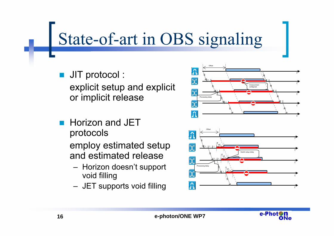
State-of-art in OBS signaling
JIT protocol :explicit setup and explicit or implicit release
Horizon and JET protocolsemploy estimated setup and estimated release– Horizon doesn’t support
void filling– JET supports void filling
t
S
S
S
t
t
tδ
δ
δ
Processing delay
Crossconnectconfigured
Offset
t
S
R
R
r
r
R
r
R
t
S
S
S
t
t
t
Tset
Tset
Tsetδ
δδ
δ
Switch setup delay
δ δ
Offset
t
S
Processing delay

17 e-photon/ONE WP7
Edge Node
Consist of electronic router and OBS interfaceFunctions– Electronic data buffering and processing– Burst Aggregation (BA), responsible for collecting data from legacy
networks and building the burst unit• impact on the overall network operation by the control of the burst
characteristics• in order to reduce the burst loss probabilities in the network the
aggregation function can segmentate data bursts for the purpose of their partially dropping in core nodes when contention occures
– Setting up the pre-transmission offset time• in simple fixed offset scheme, the offset time is calculated as a sum of
the total processing time at all the intermediate hops• offset time is one of the crucial OBS network parameter, since his
incorrect estimation has impact on data lost– Sending the control packet– Sending the burst

18 e-photon/ONE WP7
Core Node
Hardware requirements– O/E/O conversion for header processing– λ-conversion– switching speeds fast enough– eventually optical buffering (FDLs)
Operation– Processing of incoming control packets (electronically) and
sending it to the next node that lays on the routing path– Reservation of optical resources for transferring the burst
• Just-In-Time (JIT)• Horizon Reservation Mechanism (HRM)• Just-Enough-Time (JET) – the most efficient but of high complexity
– Fast optical switching with wavelength conversion and optical buffering (when available and necessary)
– Dealing with contention resolution (by a proper scheduling algorithm)

19 e-photon/ONE WP7
OBS tutorial
Burst switch architectures
20 e-photon/ONE WP7
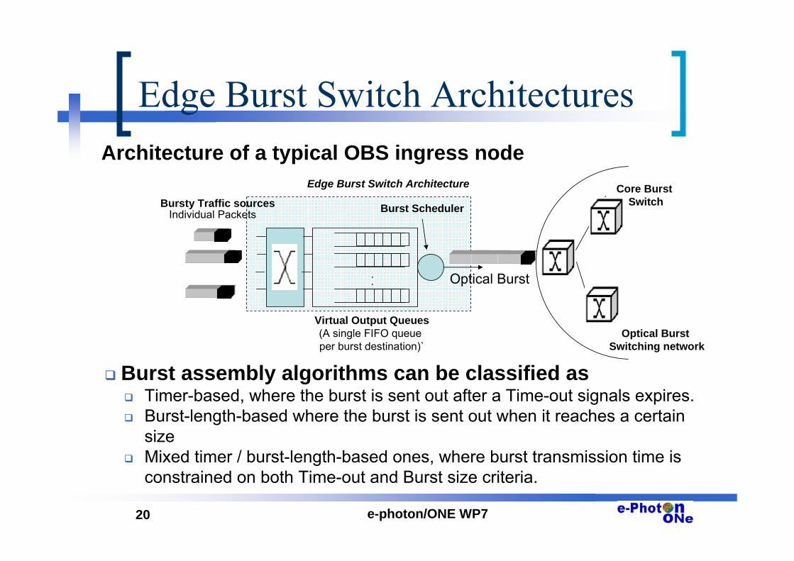
Edge Burst Switch Architectures Architecture of a typical OBS ingress node
Burst assembly algorithms can be classified asTimer-based, where the burst is sent out after a Time-out signals expires.Burst-length-based where the burst is sent out when it reaches a certain sizeMixed timer / burst-length-based ones, where burst transmission time is constrained on both Time-out and Burst size criteria.
Virtual Output Queues(A single FIFO queue per burst destination)`
..
Burst Scheduler
Optical Burst
Optical Burst Switching network
Core Burst SwitchBursty Traffic sources
Individual Packets
Edge Burst Switch Architecture

21 e-photon/ONE WP7
Core Burst Switch Architectures
Different nodes design: according to contention resolution mechanism– time domain: using Fiber-
Delay-Lines (Feed-forward and/or Feedback)
– wavelength domain via wavelength conversion
– space domain via deflection to another fiber output
Example of OBS node using feedback FDLs and tunable wavelength converters.

22 e-photon/ONE WP7
FDL Architectures
1
N ….
Input(N+M)x(N+M)
OBS switch
1
N….
1
M….
1
M….
Output
• In the feed-forward method, bursts are fed into fiber delay lines of different lengths and when they come out, they have to be switched out.
• In the feedback scheme, a burst may re-circulate as long as there is a bandwidth shortage at the output ports.
1
N
….
1
….
N
….
Input Output
NxN OBS switch

23 e-photon/ONE WP7
Implementation example of a feed forward FDLs Burst Switch architecture
Concept: Use a branch of delays per input port to scheduler packets/burst to resolve contention at the switch fabric input. Each delay branch consist of 2m-1 delay blocks, where m = logT. (For convenience T is a power of m).
The ith block consists of a three-state (or two 2x2) optical switch and three fiber delay paths, corresponding to delays equal to 0, 2i and 2i+1 slots.
The Burst Scheduler Architecture

24 e-photon/ONE WP7
OBS tutorial
Evolution of existing backbones to OBS Routing in OBS

25 e-photon/ONE WP7
Network Topology: Previous steps before OBS deployment
Scenario 0: Opaque networkLayer 1 networks are mainly based on SDH technology
Ethernet is replacing ATM as main Layer 2 technology
Stacks of SDH Metro Backbone rings
DXC DXC
ADMADM
ADMADM
..
.
ADMADM
ADMADM
..
.
DXCDXC
ADMADM
ADMADM
..
.
ADMADM
ADMADM
..
.
ADMADM
ADMADM
..
.
ADMADM
ADMADM
..
.
ADMADM
ADMADM
..
.
ADMADM
ADMADM
..
.ADMADM
ADMADM
.
.
.
ADMADM
ADMADM
.
.
.
ADMADM
ADMADM
.
.
.
ADMADM
ADMADM
.
.
.
ADMADM
ADMADM
.
.
.
ADMADM
ADMADM
.
.
.
ADMADM
ADMADM
.
.
.
ADMADM
ADMADM
.
.
.
ADMADM
ADMADM
.
.
.
ADMADM
ADMADM
.
.
.
ADMADM
ADMADM
.
.
.
ADMADM
ADMADM
.
.
.
Metro Backbone Node
Stacks of SDH Metro Access rings
Access Node
Backbone network based on PtP DWM links and
SDH rings

26 e-photon/ONE WP7
Network Topology: Previous steps before OBS deployment
> 100 METRO ACCESS NODES
...
NETWORK “B”
...
METRO BACKBONE
METRO ACCESS
NETWORK “A”
METRO BACKBONE COMPOSED OF TWO DIFFERENT NETWORKSMetro PoP
DSLAM
Current Metro Transmission Networks are based on
stacked SDH rings
Scenario 0: Opaque networkDual Homing configuration

27 e-photon/ONE WP7
Network Topology: Previous steps before OBS deployment
IP Multiservice Access Nodes (e.g xDSL, FTTH,
Wireless, etc)
•OXCDXC•OXCDXC •OXCDXC•OXCDXC
•OXCDXC•OXCDXC •OXCDXC•OXCDXC
•OXCDXC•OXCDXC
...
...
...
......
...
...
ROADMROADMROADMROADM
ROADMROADM
ROADMROADMROADMROADM
ROADMROADM
CWDM link
Several fibre links
GMPLS Mesh
ROADMROADM ROADMROADM
Optoelectronic Digital Cross Connects
Scenario 1: Hybrid NetworkCore and metro backbone networks are based on a GMPLS mesh composed of OEO DXCs
Metro Access rings are based on DWDM rings composed of ROADMs

28 e-photon/ONE WP7
Network Topology: Previous steps before OBS deployment
IP Multiservice Access Nodes (e.g xDSL, FTTH,
Wireless, etc)
•OXCOXC •OXCOXC
•OXCOXC
ROADMROADM
ROADMROADM
GMPLS Network
ROADMROADM
ROADMROADM
•OXCOXC•OXCOXC
Metro Backbone Node
Metro Access Node
IP Multiservice Access Nodes (e.g xDSL, FTTH,
Wireless, etc)
•OXCOXC•OXCOXC •OXCOXC•OXCOXC
•OXCOXC•OXCOXC
ROADMROADM
ROADMROADM
GMPLS Network
ROADMROADM
ROADMROADM
•OXCOXC•OXCOXC•OXCOXC•OXCOXC
Metro Backbone Node
Metro Access Node
Scenario 2: WS NetworkEvolution towards an all optical Layer 1 network composed of OXC and ROADMs with GMPLS
capabilities

29 e-photon/ONE WP7
OBS networks are expected to be deployed in long term scenarios with dramatically increased traffic demands and higher flexibility and granularity requirements
A natural, simple and low cost evolution from WS to OBS scenarios may be achieved by gradually updating the ROADMs and OXCspreviously used in the WS scenario in order to support optical burst transmission.
Therefore, in a first step, OBS networks may have similar topologies than WS (i.e metro access rings and core meshes).
Network Topology: First OBS deployments

30 e-photon/ONE WP7
OBS network topologies will be strongly affected by the previous network evolution
Currently, European transmission networks are mainly based on traditional SDH topologies (i.e SDH rings interconnected by DXCs).
The appearance of GMPLS is favoring the migration from static SDH ring architectures with protection mechanisms towards more flexible SDH meshed backbone network architectures including GMPLS restoration
In the short term, SDH technology is expected to be gradually migrated to Wavelength Switching (WS) due to the following drivers:
– Technological availability (appearance of the first ROADMs and OXCs)
– CAPEX and OPEX reduction, mainly due to automation and transparency, and increase of revenue coming from new services (Optical VPNs)
A feasible trend could be the evolution towards metro aggregation rings based on ROADMs and connected through a core mesh composed by OXCs with full GMPLS support.
Network Topology: Previous steps before OBS deployment

31 e-photon/ONE WP7
Network Topology: First OBS deployments
IP Multiservice Access Nodes (e.g xDSL, FTTH,
Wireless, etc)
GMPLS Network
Metro Backbone Node
Metro Access Node
•OXCOBSOXC•OXCOBSOXC
•OXCOBSOXC•OXCOBSOXC
•OXCOBSOXC•OXCOBSOXC
•OXCOBSOXC•OXCOBSOXC
•OXCOBSOXC•OXCOBSOXC
•ROADMOBSROADM•ROADMOBSROADM
•ROADMOBSROADM•ROADMOBSROADM
•ROADMOBSROADM•ROADMOBSROADM
Scenario 3: Optical Burst Switching (OBS) network –Optical equipment is updated in order to support optical burst transmission

32 e-photon/ONE WP7
Routing: OBS features
Some OBS features need to be taken into account in the routing strategy:– Calculation of the optimal value of the offset time (time
between the arrival of the control packet and the arrival of the burst)
– Contention in nodes. Buffering is still very limited.
Goals of routing in OBS– Reduce contention in nodes– Improve performance

33 e-photon/ONE WP7
Source routing
Where is routing performed?– Source and hop-by-hop routing
Source Routing– The routing decision is performed in the ingress router. The path is
not changed in the intermediate nodes.– The control packet contains the information of all the hops of the
path– The optimal value of the offset time can be calculated accurately,
because the number of hops is known – In order to consider network state, flooding the network with
congestion information is needed– Traffic engineering techniques can be used (GMPLS approach)

34 e-photon/ONE WP7
Hop-by-hop Routing
Hop-by-hop routing– Routing decision in performed in every node– The whole path and the number of hops is unknown – The value of the offset time must be estimated ( the number
of hops is not known).– Possibility to use routing algorithms of IP networks
• Need to adapt metrics to OBS– It is possible to use local congestion information (there is no
need to flood the network)

35 e-photon/ONE WP7
Contention Resolution
Performance evaluation of contention resolution schemes

36 e-photon/ONE WP7
Contention resolution
Burst loss possible due to statistical multiplexingApplication of OBS in high-speed metro/core networks– lost data has to be retransmitted on end-to-end basis (e.g. TCP)– very low burst loss probability required
need for highly effective contention resolution
Domains of contention resolutionWavelength domain wavelength conversion
• very effective as all WDM channels shared among all bursts• but: low burst loss probabilities only for many λs
additional schemes necessary, combinations beneficialTime domain fiber delay lines (FDLs)Space domain deflection/alternative routingSegmentation only conflicting part of burst dropped

37 e-photon/ONE WP7
Contention resolution
Reservation of buffer FDL and output wavelength– PreRes: early reservation of output together with buffer, no reloop– PostRes: reservation of output only after buffering time b
offset δ new burst
reserved
buffer FDL
reservationrequest
output λ
OK
NO
output λ
buffered burst
reserved
buffer FDLbuffered burst
buffered burst
FDL delay b
offset δ
expanded offset b + δPreRes
PostResb
Use of FDL buffer in case of blocked output wavelength

38 e-photon/ONE WP7
FDL buffer dimensioning
Combination of FDL and converters: Conv firstDelay b of FDL 1 should be a few mean burst lengths hIncreasing FDL count improves performanceLower load or more wavelengths per output make FDL more efficient
FDL Buffer
with λ conversion
Shared FDL buffer, PreResDelay of FDL 1: bDelay of FDL i: i*b

39 e-photon/ONE WP7
Case Study: Shared Conv Pool
Significant converter savings possibleFor realistic load values up to 50-75% savings possible
N=1 is case of share-per-output pool
Share-per-node converter poolM = 16 wavelengths per fiberN output fibersC convertersConversion ratio = C / (M*N)

40 e-photon/ONE WP7
Case study: Optimized CR
Combination of FDL buffers and shared converter poolsStrategy for selecting resources has significant impact
– Red: strategy that minimizes converters (minConv)– Blue: strategy that minimizes FDL usage (minDelay)
……
…
……
1
NC
… …
1
2
N
1
2
N
M
…
1
NF
…
…
M
Share-per-nodeM = 8 wavelengths N = 8 output fibersNC tun. convertersNF FDLsrC=NC/(MN)
41 e-photon/ONE WP7
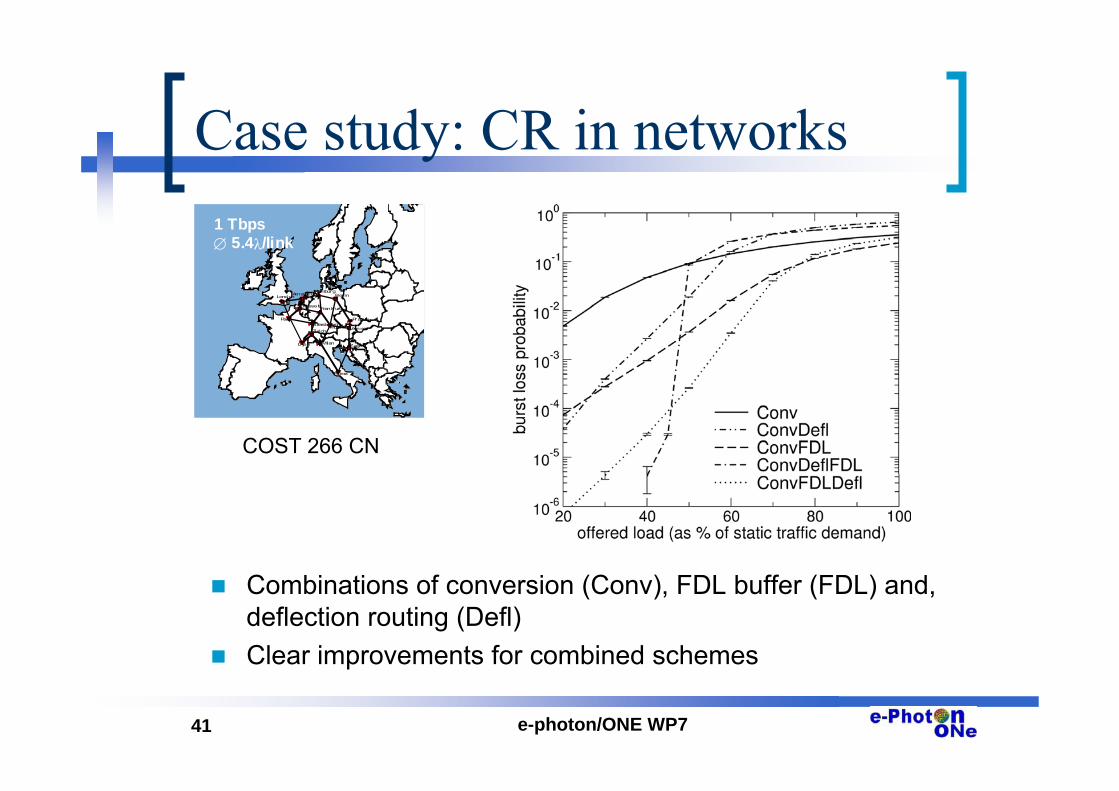
Case study: CR in networks
Combinations of conversion (Conv), FDL buffer (FDL) and, deflection routing (Defl)Clear improvements for combined schemes
London
Par is
Brussels
HamburgAmsterdam
Strasbourg
Zurich
Lyon Milan
Munich
Frankf urt
Berlin
Prague
Vienna
Zagreb
Roma
1 Tbps∅ 5.4λ/link
COST 266 CN

42 e-photon/ONE WP7
OBS tutorial
Traffic models

43 e-photon/ONE WP7
Traffic models for OBS
The generated OBS traffic depends on– Burstification algorithm– Input traffic features:
• Long-range dependence• Instantaneous burstiness
No single traffic model can portray all possible scenarios!

44 e-photon/ONE WP7
Bustification algorithms
Time-based, burst-size based or mixed-time-size basedIn all cases input traffic goes through demultiplex and then burst formation queues

45 e-photon/ONE WP7
Traffic models
Long-range dependence happens from a cutoff timescale, beyond which traffic may show independent incrementsFor time-based burstifiers only the number of bytes per interval mattersFor burst-size-based burstifiers the packet arrival dynamics matter

46 e-photon/ONE WP7
Burst size
For time-based burstifiers: Gaussian (or Gamma)For burst-based burstifiers: Constant

47 e-photon/ONE WP7
Long-range dependence
Long-range dependence is inherited at large timescales only but at short timescales the statistical interleaving of bursts produces independent traffic

48 e-photon/ONE WP7
Burst interarrival time
If many burstifier queues are statistically multiplexed to the same wavelength: Poisson at the burstifier output!

49 e-photon/ONE WP7
OBS tutorial
TCP over OBS
50 e-photon/ONE WP7
Basic TCP control functions
Flow control– the TCP window size is used to prevent
the sender from flooding the receiverCongestion control– TCP window is dynamically updated in
relation to the network state as perceivedby the sender

51 e-photon/ONE WP7
TCP Congestion Control
Congestion window adaptation– Additive increase/multiplicative decrease
ssthresh = 8 ssthresh = 10
cwnd = 20
After timeout
0
5
10
15
20
25
0 3 6 9 12 15 20 22 25
Time (round trips)
Con
gest
ion
win
dow
(seg
men
ts)

52 e-photon/ONE WP7
TCP loss detection Retransmission Time Out (RTO)Triple duplicate ACKs (TCP Reno)– Fast retransmit/Fast recovery
Con
gest
ion
win
dow
(seg
men
ts) fast retransmittriple dup acks
Time (s)

53 e-photon/ONE WP7
Impact of OBS network on TCP
Edge node• Assembly algorithms
– Mixed flow/ per flow– Time out, threshold-based
Core node• Scheduling algorithms• Contention resolution schemes
– Wavelength domain – Time domain
Network• Routing algorithms
– Deflection routing– QoS routing
TCP performance (throughput, fairness)
is influenced by OBS networks

54 e-photon/ONE WP7
Classes of TCP sources
Fast source
– All segments of the maximumwindow are emitted in Tb
Slow sources
– At most one segment emitted in Tb
Medium source
ba
m TB
LW≤
a
mb
a BLWT
BL
<<
ba
TBL
≥
Optical bursts
Ba (bit/s) access network rate, L (bit) segment length, Wm (bit) maximum window size, Tb (s) burstification time out
cr1

Diapositiva 54
cr1 TCP performance depends on the number of segments collected in a single burst. This in its turn depends on access speed. Iit is convenient to classify sources in relation to speed into three main classes: fast, slow, intermediate.carla, 7/21/2005

55 e-photon/ONE WP7
Burst loss
Multiple segment losses– Depend on the level of aggregation of segments
in a burstRetransmission time out is the mainindication of loss for fast sources– Congestion window shrinks to 1 MSS when a
burst is lostSlow sources recover mainly by means of fast recovery/fast restransmit
Burst loss is a consequence of contention in core nodes
cr2

Diapositiva 55
cr2 TCP performance are mainly determined by reaction of the TCP sources to burst loss. Burst losses are caused by contention in core nodes and cause correlated multiple segment losses in the general intermediate case. As a consequence the main reaction is retransmission time out. On the other hand slow sources recover mainly by means of fast recovery/fast restrasmit because of absence of correlation in segment losses.carla, 7/21/2005

56 e-photon/ONE WP7
Correlation benefit
Effect related to correlated segmentdelivery– Fast/medium source
Fast window reopening is due toconcentrated acksCongestion window quickly reaches itsmaximum value
cr3

Diapositiva 56
cr3 The correlation benefits arise as a consequence of correlated delivery of the segments in the same burst. This delivery causes fast reopening ofthe congestion window for fast and intermediate sourcescarla, 7/21/2005

57 e-photon/ONE WP7
TCP send rate for different sources
Bo = 2.5 Gb/secRTT =600 msMax window size Wmax=128 MSSMSS = 512 bytesTb= 3 ms
0.10.0001 0.001 0.01Burst Loss Probability
TCP
Sen
dra
te (b
it/se
c)
0
1.0e+06
8.0e+05
6.0e+05
4.0e+05
2.0e+05
Ba=200 Mb/s (fast)Ba=100 Mb/s (medium)
Ba=1 Mb/s (slow)
IR ERTCP
SourceTCP
Receiver
Access link
Ba Bo
Optical Core Switch
Optical link
Optical Core Network
IWU IWU
More segments are in a burst, the higher the
TCP performance

58 e-photon/ONE WP7
Variable delay
Delay due to burst assembly task• Edge architecture• Algorithm employed (Time out, threshold-based,…)
Delay due to the presence of FDLs• Core architecture
Delay due to the scheduling algorithm

59 e-photon/ONE WP7
Modeling TCP throughput A simple model is able to calculate throughput as a functionof burst loss probability p– p is a Bernoulli r.v.– Aggregation is accounted through the average number of
segment in a burst E[N]The average TCP throuhput is calculated starting from the formula
– where E[Y] is the average number of segments transmitted in bursts during the interval I between two time out periods and E[R] is the average number of segments transmitted duringthe time out period ZTO
The result is
][][][][
TOTCP ZEIEREYEB
++
=
)( pFBTCP =p is due to losses
arising in the network and in the core nodes

60 e-photon/ONE WP7
OBS tutorial
Analytical techniques for OBS
61 e-photon/ONE WP7
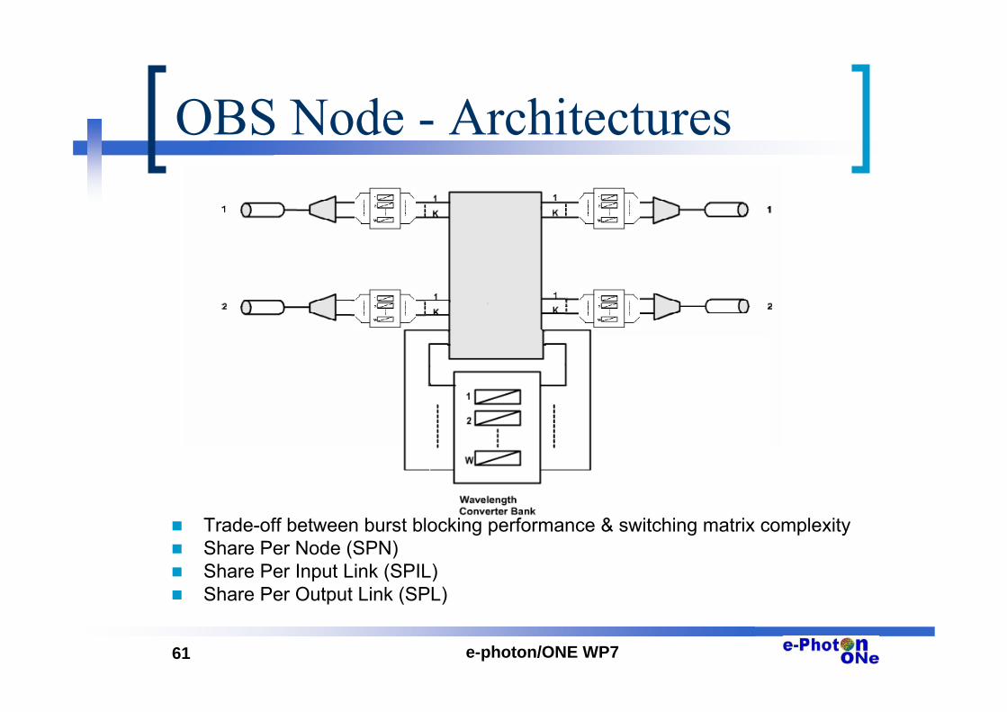
OBS Node - Architectures
Trade-off between burst blocking performance & switching matrix complexityShare Per Node (SPN)Share Per Input Link (SPIL)Share Per Output Link (SPL)

62 e-photon/ONE WP7
OBS Node Model – SPLK wavelength channels per fiber. A Wavelength Converter (WC) bank of size 0 < W < K per output fiber; (Share Per output Line).Burst arrival process is Poisson with rate λ.The wavelength channel they arrive on is uniformly distributed on (1,K). Burst durations are exponentially distributed with mean 1/µ.A new burst arriving at the switch on wavelength w and destined to output line k
– is forwarded to output line k without using a converter if channel w is available, else
– is forwarded to output line k using one of the free WCs in the converter bank and using one of the free wavelength channels selected at random, else
– is blocked

63 e-photon/ONE WP7
OBS Node Analysis
W = K, Full Wavelength Conversion (FWC)– M/M/K/K loss system with offered load r=λ/µ– Erlang-B loss formula
W=0, No Wavelength Conversion– K independent M/M/1/1 loss systems each with offered load
r=λ/µK0 < W < K, Partial Wavelength Conversion (PWC)– Can one have an exact analysis?– Seek numerically stable and efficient computational
schemes

64 e-photon/ONE WP7
OBS Node Analysis
Formulated as the steady-state solution of a structured Markov chainKnown as nonhomogeneous QBD(Quasi-Birth-Death-Process) in the applied probability literatureStable and efficient way to solve based on block LU factorizationsComputational complexity lessthan O(K W3 ) compared the brute
force approach O(K3 W3)
0 1
0 1 2
1 2
1
1
,
0, 1
K
K K
K
b K i wi W
A UD A U
Q D AU
D AxQ xe
iP x e xK
−
−
=
⎡ ⎤⎢ ⎥⎢ ⎥⎢ ⎥=⎢ ⎥⎢ ⎥⎢ ⎥⎣ ⎦
= =
= +∑
O
O O

65 e-photon/ONE WP7
SPL - PWC Results
Model can be used for – Rapid production of burst loss curves– Iterative methods for finding cost-optimal choices for the pair
(K,W) so as to satisfy a QoS requirement in terms of burst loss

66 e-photon/ONE WP7
Network-wide Study – Reduced Load Fixed Point Approximations
Reduced offered loads are obtained by
where
– I(i,j,r) 1 or 0 whether or not i ∈ r and link i strictly precedes link j along route r
– B vector of blocking probabilitiesEvaluate Bj’s by using ρj’s on each link by using the PWC model described before, denoted as PWC(ρj,Wj,K )
By successive iterations, approximate blocking probabilities could be obtained.
( ), ,j j jB PWC W K= ρ
( )1
1
1 ( , , ) ,j
J
j j r ir R i
I i j r Bρ µ λ−
∈ =
= − ×∑ ∏

67 e-photon/ONE WP7
OBS tutorials
OBS testbeds

68 e-photon/ONE WP7
Core OBS Node Technology
Traditionally OBS switches are based on slow switching technology (e.g. MEM)– Suitable for long bursts with large offset time– Not suitable for networks with large number of users
transmitting small data bursts• Not efficient for short bursts with short offset time
Combination of fast and slow optical switching technology is emerging for future OBS networks– SOA based switch technology for fast switching– MEM based switch technology for slow switching

69 e-photon/ONE WP7
Core OBS Node Architecture
SOA
6dB
GCSR Tun. Laser
DI: 6.45cm
Label Extraction
10%
90%
Optical Packet Switch input
F P G A b o a r d
λ0
D/A
CD
/A C
IC
IR
λ1 λ4
EAM÷4
Optical Burst Switch Control
Serial to parallel
Parallel to serial
AW
G
IM
PM
λconv1
λconv2
λconv3
λconv4
SOA
SOA
SOA
SOA
1
Pow
er m
on
Com
bine
r
Pow
er
adju
stm
ent
CCU
2
Pow
er m
on
Com
bine
r
Pow
er
adju
stm
ent
Pow
er m
on
Com
bine
r
Pow
er
adju
stm
ent
3
SMU1Pow
er m
on
1
8
1
8
1
8
8 1
EDFA
EDFA
EDFA
Drop
λ9
λ16
λ9
λ16
λ9
λ16
81
Pow
er m
on
1
2
3
Pow
er m
on
SMU8
EDFA
EDFA
EDFA
CDU8x8
1
Pow
er m
on
Com
bine
r
Pow
er
adju
stm
ent
2
Pow
er m
on
Com
bine
r
Pow
er
adju
stm
ent
Pow
er m
on
Com
bine
r
Pow
er
adju
stm
ent
3
MEMPow
er m
on
1
8
1
8
1
8
1
8
1
8
1
8
8 1
EDFA
EDFA
EDFA
ADD
λ9
λ16
λ9
λ16
λ9
λ16
81
Pow
er m
on
1
2
3
Pow
er m
on
MEM8
EDFA
EDFA
EDFA
8x8
MEM basedslow switch
SOA basedfast switch
OXCm xm
Contro l Header ProcessingO E
l1
λ n
λ 1
λ n
l m
λ 1
Fast Switch
OXCm xm
OXCm xm
Fast Switch
…
…
…

70 e-photon/ONE WP7
User data (electronic packets) are aggregated in optical bursts based on:• Destination address • Class of service
Optical bursts are scheduled for transmission based on :• Number of bytes per optical burst• Maximum experienced delay
Optical control packet and wavelength are assigned based on:• Destination address and class of service • Information from control plane (lookup table)
Class-basedTraffic aggregation
Optical Burst construction /scheduling
Wavelengthtable
Burst control Packetinsertion
E/Oconversion
Optical fibre
Edge OBS Node Functionality

71 e-photon/ONE WP7
Edge OBS Node Architecture
Client Traffic
ClientTraffic
GigabitEthernetInterface
Traffic Aggregation
Header(BCH)
Lookup Table
Header(BCH)
Generator
Data BurstBuffer
Wavelengthlookup table
NetworkProcessor
4×3.1 Gbps
3.1 Gbps
High-precisionDAC
High-precisionDAC
High-precisionDAC
Impedance matching
Impedance matching
Impedance matching
GCSR Laser
Coupler
Reflector
Phase
MUX
λ1
λ1, λ2λ3, λ4
Coupler
12.5 Gbps
AW
G
Gigabit Ethernet
High-Speed FPGA with embedded
processor(VIRTEX II Pro)
Tuneable Laser Controller
Optical amplifier 3db coupler Polarization controller Mach-Zehnder modulatorOptical amplifier 3db coupler Polarization controller Mach-Zehnder modulator
Class-based Optical burst Assembly
Burst Control Header (BCH)
Data Burst
Control planesignalling (UNI)
1543.7nm1536.6nm
BCH Data Burst16400 bytes
Offset time18uSec

72 e-photon/ONE WP7
Optical Burst Construction (Results)
The length of payload is variable : 3KBytes, 16KBytesOptical Burst size are multiple integral of 100 bytesOptical Bursts modulate in four different wavelengths (1536.6, 1543.7, 1546.1, 1548.5 nm)Programmable BCP (length here =80 bytes=preamble+label+burst length+offsettime+wavelength)Offset time variable Guard band between two adjacent bursts is variable based on the traffic load
λ11543.71536.6λ2
BCP Data Burst16200 bytesOffset time
18uSec
λ1 λ2 λ3 λ4 λ1
5uS/div BCH@
3.125Gbps
Data Burst@
12.5Gbps

73 e-photon/ONE WP7
Edge & Core Routers
Burst Generator
+Tuneable laser
Fast SOA-Based
Switch
SlowMem-based
Switch

74 e-photon/ONE WP7
OBS tutorial
Resilience

75 e-photon/ONE WP7
Resilience – OBS challenges (1)
Main rationale for an OBS network:– Use of packet based information transport
is increasing.– Resilience functionality comparable to
SDH/SONET must be present in packet based optical networks.
Disruption of service delivery due to:– Fibre cuts.– Component/node failure.

76 e-photon/ONE WP7
Resilience – OBS challenges (2)
Specific Resilience challenges for OBS:– Use of offset time reservation protocol
=> vulnerability to loss of both control packet and data bursts.
– Detecting failures by detecting loss of control messages => increased overhead and congestion due to need of frequent control message transmission.
– No optical RAM for buffering during restoration.
77 e-photon/ONE WP7
Resilience - Main approaches
Two main approaches:– Fault avoidance: minimize the probability
of faults in the network.– Fault tolerance: continue to provide the
intended service even when faults occur.Faults can never be completely avoided =>Goal: We should aim at building a fault-tolerant (survivable) OBS network.

78 e-photon/ONE WP7
Resilience - Fault-tolerance (1)
Building fault-tolerance into a network by adding redundancy at different levels:
Redundancy
Component redundancy Node redundancy Network redundancy
Active or passive spare components used in a node.Duplicated links between two nodes.
Duplication of a full switching node; active or passive operation.
End-to-end redundant paths used in the network; back-up may be pre-planned.

79 e-photon/ONE WP7
Resilience - Fault-tolerance (2)
Mechanisms to achieve network redundancy involves control signalling and have slower response times than (local) mechanisms to achieve component or node redundancy.Coordination between mechanisms at different levels is important (e.g. avoid rerouting of traffic end-to-end if a local mechanism may be sufficient to handle the problem).
Any fault must be reported to the control level for follow-up (e.g. change of spare part).

80 e-photon/ONE WP7
Resilience - Differentiation (1)
We should aim at differentiated Resilience:– To optimize resource utilization.– To enable price discrimination.
The Resilience level and performance level should be independently chosen:– A service with high performance (e.g. real-time)
demands may have low Resilience demands.– A given service may have different Resilience
demands in different situations or contexts.

81 e-photon/ONE WP7
Resilience – Differentiation (2)
CoSn
CoS2
CoS1
DC1 DC2 DCn
Service a
Service b
Service-session a1
Service-session a2
Service class
Service-session b1
Notation
Resilience class
A ”service-session” is a given service used in a given situation or context.

82 e-photon/ONE WP7
Resilience - Differentiation (3)
Examples:High picture-quality video-telephony:– High performance demands (wrt. real-time and packet loss)– Moderate to low Resilience demands depending on context.
Messaging services:– Have in general very low performance demands.– May have very high Resilience demands if used in a business
context.Regular phone call vs. Emergency phone call:– Both have the same performance demands
(high real-time demands but moderate packet loss demands)– Regular phone call has moderate Resilience demands;
Emergency phone call has very high Resilience demands.i.e. even the same service may have very different Resilience
demands in different contexts.

Optical Burst SwitchingA tutorial from E-photon/ONe
The VD1 OBS taskforce