optical axis alignment for three-aspherical mirrors system using five parallel laser beams and...
TRANSCRIPT
INTERNATIONAL JOURNAL OF PRECISION ENGINEERING AND MANUFACTURING Vol. 14, No. 3, pp. 381-386 MARCH 2013 / 381
© KSPE and Springer 2013
Optical Axis Alignment for Three-Aspherical MirrorsSystem Using Five Parallel Laser Beams and MoiréMethod
Der-Chin Chen1,#
1 Department of Electrical Engineering, Feng Chia University, 100, Wenhwa Road, Seatwen, Taichung, Taiwan, ROC, 40724# Corresponding Author / E-mail: [email protected], TEL: +886-4-2451-7250, Ext. 3845, FAX: +886-4-2451-6842
KEYWORDS: Alignment, Aspherical mirror, Effective focal length
In this paper, a new optical technique involving the five parallel laser beams alignment device and moiré method was developed to
rapidly and accurately align the optical axis of three-aspherical mirrors system (TAMS). In this method, the optical axis of a first
aspherical mirror is made parallel to the “five incident parallel laser beams” in the plane of incidence. The height and orientation
of the first aspherical mirror are fine tuned and the alignment is assured by examining the direction of these five reflected laser beams.
The optical axes of second and third aspherical mirror are aligned by five parallel laser beams in accordance with the configuration
parameter of optical system in sequence. The effective focal length (EFL) of the TAMS was measured by moiré method and image
formula. This novel method is used to align the optical axis of TAMS and the EFL deviation estimated has an accuracy of 1%.
Manuscript received: August 22, 2012 / Accepted: December 4, 2012
1. Introduction
Reflective optical systems provide superior thermal stability and
radiation resistance and offer lower image defects arising from
chromatic aberration. The reflective optical systems provide superior
performance over refractive optical systems as it can be made far more
compact and operated on a wider spectral range. Compared with the
refractive system, an all-reflective system increasing the number of
elements provides additional opportunities to eliminate or correct more
aberrations. It is widely used in evaluating the performance of optical
system and is applied to the reflecting telescope, and extreme
ultraviolet (EUV) lithographic projection. As three-aspherical mirrors
system (TAMS) becomes more complex, precise optical axis alignment
becomes more challenging as well. The manufacturing and alignment
of TAMS usually involves a sophisticated and expensive optical
instrument, such as laser unequal path interferometer, autocollimator or
knife edge method, which identify TAMS’s characteristics like effective
focal length, back focal length, and other optical parameter.1-4 Above
traditional optical instruments aligning the optical axis of TAMS cost
much of time. Because of the above concerns, a new optical technique
was designed to align the optical axis of the TAMS using the five
parallel laser beams and measure the EFL of TAMS by moir method.
There are some advantages in this method: (1) It is a rapid and simple
alignment method. (2) It simplifies the electro-optics system and lowers
the cost. (3) The different wavelengths of laser diodes are used to
enable getting wider spectral range of optical system alignment. (4)
The five parallel laser beams arrangement, it adjusts the optical axis of
TAMS with more freedoms of orientation. This is a rapid method for
measuring the EFL deviation up to 1% accuracy after aligning the
optical axis of the TAMS.
2. Basic principle
TAMS that consists of three mirrors and two thicknesses is
indicated in the Fig. 1. Three mirrors, named first aspherical mirror,
second aspherical mirror and third aspherical mirror, are arranged in
TAMS configuration that reflects light from the object to the image
through three mirrors in order. There is at least one intermediate image
formed between the first and third mirror and at least one of the three
aspherical mirrors is non-rotationally symmetric. The radiuses of three
mirrors are labeled r1, r2 and r3, the axial distance between first mirror
to second mirror is d1, the axial distance between the second mirror to
third mirror is d2. The conic constants of three surfaces are k1, k2 and
DOI: 10.1007/s12541-013-0053-7

382 / MARCH 2013 INTERNATIONAL JOURNAL OF PRECISION ENGINEERING AND MANUFACTURING Vol. 14, No. 3
k3 and the aperture sizes of three mirrors are labeled h1, h2 and h3. The
surface profile parameters of optical system can be described as three
parts: (1) the first obstacle ratio is given by: α1 = l2/f1 = h2/h1, where α1
is the obstacle ratio of the second mirror relative to the first mirror, l2
is the axial distance of vertex point of second mirror to the focal point
of first mirror and f1 is the focal length of first mirror. (2) similarly, the
second obstacle ratio is given by: α2 = l3/l’2 = h3/h2, where α2 is the
obstacle ratio of third mirror relative to second mirror, l’2 is axial
distance of the vertex point of second mirror to the focal point
combining the first mirror with the second mirror, l3 is axial distance
of the vertex point of third mirror to the focal point combining the first
mirror with the second mirror. (3) eventually, the magnification
equations are β1 = l’2/l2 ≒u2/u’2 and β2 = l’3/l3≒ u3/u’3, where β1 is
the magnification of second mirror, β2 is the magnification of third
mirror; l’3 is the vertex point of third mirror to the focal point of TAMS
axial distance. The structure parameters of optical system are derived
by the ynu paraxial ray tracing in Gaussian optics.5,6 These structure
parameters are given by the expression:
(1)
(2)
(3)
(4)
(5)
where f is the focal length of TAMS. When the following aberration
parameters, the spherical aberration, coma, astigmatism given by
system, the surface profile parameters α1, α2, β1, β2 and conic constant
of three surfaces could be designed. Then the solution of system
structure parameter will be calculated by the above five equations and
configuration parameters. When α1 > 1, α2 < 0, β1 < 1, and β2 > 0,
TAMS with at least one intermediate image located between the first
and third mirrors is one type of three TAMS solution. Besides above
eight alignment configuration parameters of TAMS, the concerns about
the depth of focus (DOF) in the process of alignment to the optical axis
should be deliberated.
The concept of depth of focus rests on the assumption that for a
given optical system, there exist a blur (due to defocusing) of small
enough size such that it will not adversely affect the performance of the
system. The depth of focus, shown in Fig. 2, is the amount by which the
image may be shifted longitudinally (δ) with respect to the reference
plane and which will introduce no more than the acceptable blur. The
size of the DOF of lens using geometry optics could be obtained.
In Fig. 2, D is the distance from exit pupil to the reference plane,
and B is the diameter of the blur spot or linear blur. Then it shows
(6)
where ψ is called angular blur.
Apparently, if reference plane is sit on the image plane, then B = 0,
and ψ = 0.
According to the analysis of DOF, this paper selects the smallest
blur that serves as the focal point to implement the alignment to the
optical axis and measurement of focus length.7
3. The optical alignment system
We develop a specific technique to align the optical axis of the
TAMS by five parallel laser beams and then measure its EFL by moiré
method. This alignment system can applies to UV ~ IR regions with
the different wavelengths of alignment laser diode. The optical
alignment system in Fig. 3 is composed of as followings: (1) the
TAMS as shown in Fig. 4(a), (2) the alignment device as shown in Fig.
r1
2
β1β2
-----------f=
r2
2α1
1 β+1
( )β2
-----------------------f=
r3
2α1α2
1 β+2
( )----------------- f=
d1
r1
2---- 1 α
1–( )=
d2
r1
2----α
1β1
1 α2
–( )=
ψB
D----=
Fig. 1 Three-aspherical mirrors system
Fig. 2 Depth of focus δ of optical system
Fig. 3 The configuration of the optical alignment system
INTERNATIONAL JOURNAL OF PRECISION ENGINEERING AND MANUFACTURING Vol. 14, No. 3 MARCH 2013 / 383
4(b) and (c), (3) pinhole and the line grating and (4) optical table and
mount. Functions of four parts are simply described as follows.
3.1 Three-aspherical mirrors system
The objective of alignment to TAMS, the main part of the optical
alignment system and consisting of three aspherical mirrors, is to adjust
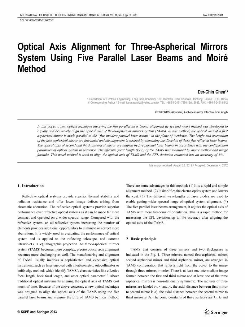
three dimensional optical alignments. Fig. 4(a) shows the photograph
of TMAS under alignment and use for the reflective collimator of a
dynamic infrared scene projector system.
3.2 Alignment device
The alignment device includes five parallel semiconductor lasers,
the rotation mechanism, precise adjustable holder and the fixture. The
semiconductor laser beams on the fixture are made parallel each other
with precise adjustable holder and perpendicular to the surface fixture.
An adjustable holder for mounting and orienting the semiconductor
laser is set by a removable retaining laser within a mount of ring.
The rotation mechanism adjusts the initially horizontal laser beams
to any direction as shown Fig. 4(b). For example, the three laser beams
lines horizontally, i.e., #1, #2, and #3 from right to left and the three
laser beams lines vertically, i.e., #5, #2, and #4 from up to down as
shown in Fig. 4(b). In the rotation mechanism, it can rotate any degree
to adjust the three-dimensioned optical axis of TAMS at any tilted and
yawed angle.
3.3 Pinhole and grating
The pinhole has a size of 30ìm. When the diffraction pattern of
concentric circular rings was appeared, the laser beam passes through
the pinhole accurately. The diffraction patterns formed by a pinhole
consist of a central bright spot surrounded by a series of bright and dark
rings. We can describe the pattern in terms of the angle θ, representing
the radius angle of each ring. If the aperture diameter is W (mm) and
the wavelength is λ (mm), the radius angle θ of the first dark ring is
given by sin θ = 1.22 (λ/W). With this diffraction technique, the
pinhole is used to precise align laser beam parallel to the TAMS of the
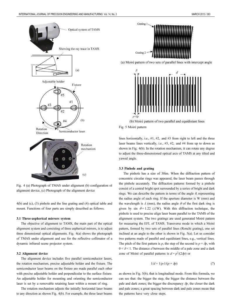
alignment system. The two gratings are used generated Moiré pattern
for measuring the EFL of TAMS. Transverse mode in which a Moiré
pattern, formed by two sets of parallel lines (Ronchi grating), one set
inclined at an angle to the other is shown in Fig. 5(a). Let us consider
two patterns made of parallel and equidistant lines, e.g., vertical lines.
The pitch of the first pattern is p, the step of the second is p + δp, with
0 < δ < 1. The distance d between the middle of a pale zone and a dark
zone of Moiré of parallel patterns is d = p2/(2δp) or
1/d = 1/p-1/(p + δp) (7)
as shown in Fig. 5(b), that is longitudinal mode. From this formula, we
can see that: the bigger the step, the bigger the distance between the
pale and dark zones; the bigger the discrepancy δp, the closer the dark
and pale zones; a great spacing between dark and pale zones mean that
the patterns have very close steps.
Fig. 4 (a) Photograph of TMAS under alignment (b) configuration of
alignment device, (c) Photograph of the alignment device
Fig. 5 Moiré pattern
384 / MARCH 2013 INTERNATIONAL JOURNAL OF PRECISION ENGINEERING AND MANUFACTURING Vol. 14, No. 3
4. Experiments and Results
The conditions and specifications used for the experiment are listed
in Table 1. These specifications consist of three parts, TAMS that has
75 mm EFL, two linear gratings and a CCD camera. Due to
sophisticated experiments, experimental procedures are divided into
two parts as following:
4.1 Pre-Experiment
Pre-Experiment of five semiconductor laser beams fine adjustment:
(1) The fixture of alignment device is vertically (perpendicular) put on
the optical table such that laser beam #2 is nearly parallel to the
surface of the optical table.
(2) The precise adjustable holder is fine adjusted to make the laser
beam #2 parallel to the surface of the optical table. To check the
parallelism, the pinhole is moved on the optical table from
position 1 to position 2 (about 50 cm distance) with a fixed height
and the pinhole diffraction pattern that the laser beam passes
through the pinhole accurately was observed. Above method is
repeated until the laser beam #4, #5, #3 and beam #1 are parallel
to the surface of the optical table, respectively.
(3) The plane mirror is put on the optical table at 3 meter distance
from the alignment device. To adjust the plane mirror, the
reflected beam #2 is made parallel to the optical table. To check
the plane mirror perpendicular to the optical table, a piece of paper
was used to chop reflected beam #2. The reflected beam #2 must
be coaxial to the incident laser beam #2 by adjusting the precise
adjustable holder.
(4) Step (3) is repeated until the reflected laser beam #4, #5, #3 and
#1 are coaxial to the incident laser beam #4, #5, #3 and #1,
respectively.
4.2 Experiment with TAMS
The TAMS alignment experiment can be divided into two main parts.
Part 1: the optical axis of first aspherical mirror alignment
(1) The first (1st) aspherical mirror is adjusted at first so that its optical
axis is in the incident plane made by three horizontal parallel
incident laser beams.
(2) The1st aspherical mirror is adjusted again so that the three
horizontal parallel reflected beams come to a focus at the same
point, i.e., the saggital optical plane of the 1st aspherical mirror
was found.
(3) Three vertical parallel incident beams are parallel to optical axis by
adjusting the 1st aspherical mirror and the three vertical reflected
beams also come to a focus at the same point obtained in (1), i.e.,
the tangential optical plane of the 1st aspherical mirror is found.
(4) The horizontal focal point and vertical focal point are gone to one
point together.
(5) Capture the focus pattern at the reference plane (ref. Fig.2) with
the CCD camera. The reference plane is moved from left to right
of the image plane to see if it fits Eq. (6).
Part 2: the alignment of the optical axis of the second (2nd) and third
(3rd) aspherical mirror in sequence
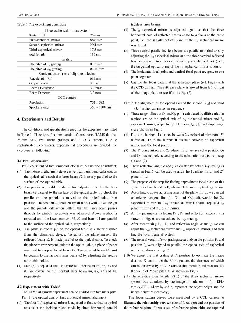
(1) These tangent lines at Q2 and Q3 point calculated by differentiation
method are on the optical axis of 2nd aspherical mirror and 3rd
aspherical mirror, respectively. The point Q2 ,Q3 and slope angle
θ are shown in Fig. 6.
(2) D21 is the horizontal distance between 2nd aspherical mirror and 3rd
mirror and D3 is the horizontal distance between 3rd aspherical
mirror and the focal point.
(3) The 1st plane mirror and 2nd plane mirror are seated at position Q2
and Q3, respectively according to the calculation results from step
(1) and (2).
(4) These reflection angle α and γ, calculated by optical ray tracing as
shown in Fig. 6, can be used to align the 1st plane mirror and 2nd
plane mirror.
(5) The purpose of the step for finding approximate focal plane of this
system is solved based on D3 obtainable from the optical ray tracing.
(6) According to above adjusting result of the plane mirror, we can get
optimizing tangent line (at Q2 and Q3), afterwards the 2nd
aspherical mirror and 3rd aspherical mirror should replaced 1st
plane mirror and 2nd plane mirror.
(7) All the parameters including D21, D3 and reflection angle α, γ as
shown in Fig. 6, are calculated by ray tracing.
(8) After ascertaining D21, D3 and reflection angle α and γ, we can
adjust the 2nd aspherical mirror and 3rd aspherical mirror, and then
find the focal plane of system.
(9) The normal vector of two gratings separately at the position P1 and
position P2 were aligned to parallel the optical axis of aspherical
mirror, as shown in Fig. 7.
(10) We adjust the first grating at P1 position to optimize the image
distance X2 and to get the Morie pattern, the sharpness of which
can be observed by a CCD camera that monitor and measure it’s
the value of Moiré pitch d, as shown in Fig. 7.
(11) The effective focal length (EFL) of the three aspherical mirror
system was calculated by the image formula (m = h2/h1= EFL/
x1 = -x2/EFL, where h1 and h2 represent the object height and the
image height respectively.)
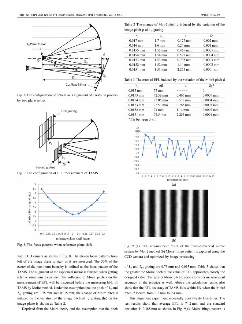
The focus pattern curves were measured by a CCD camera to
illustrate the relationship between size of focus spot and the position of
the reference plane. Focus sizes of reference plane shift are captured
Table 1 The experiment conditions
Three-aspherical mirrors system
System EFL 75 mm
First-aspherical mirror 88.6 mm
Second-aspherical mirror 29.4 mm
Third-aspherical mirror 17.5 mm
total length 110 mm
Grating
The pitch of 1st grating 0.75 mm
The pitch of 2nd grating 0.015 mm
Semiconductor laser of alignment device
Wavelength (λp) 635 nm
Output power 3 mW
Beam Divergence < 2 mrad
Beam Dimeter 3.3 mm
CCD camera
Resolution 752 × 582
Spectral range 350 ~ 1100 nm
INTERNATIONAL JOURNAL OF PRECISION ENGINEERING AND MANUFACTURING Vol. 14, No. 3 MARCH 2013 / 385
with CCD camera as shown in Fig. 8. The eleven focus patterns from
left of the image plane to right of it are measured. The 30% of the
center of the maximum intensity is defined as the focus pattern of the
TAMS. The alignment of the aspherical mirror is finished when getting
relative minimum focus size. The influence of Moiré pitches on the
measurement of EFL will be discussed before the measuring EFL of
TAMS by Moiré method. Under the assumption that the pitch of 1st and
2nd grating are 0.75 mm and 0.015 mm, the change of Moiré pitch d
induced by the variation of the image pitch of 1st grating (h2) on the
image plane is shown as Table 2.
Deprived from the Moiré theory and the assumption that the pitch
of 1st and 2nd grating are 0.75 mm and 0.015 mm, Table 3 shows that
the greater the Moiré pitch d, the value of EFL approaches closely the
designed value. The greater Moiré pitch d serves to better measurement
accuracy in the practice as well. Above the calculation results also
show that the EFL accuracy of TAMS falls within 1% when the Moiré
pitch d locates from 1.2 mm to 2.4 mm.
This alignment experiment repeatedly does twenty five times. The
test results show that average EFL is 74.2 mm and the standard
deviation is 0.388 mm as shown in Fig. 9(a). Moiré fringe pattern is
Fig. 6 The configuration of optical axis alignment of TAMS in process
by two plane mirror
Fig. 7 The configuration of EFL measurement of TAMS
Fig. 8 The focus patterns when reference plane shift
Table 2 The change of Moiré pitch d induced by the variation of the
image pitch p of 1st grating
h2 x2 d δp
0.017 mm 1.7 mm 0.127 mm 0.002 mm
0.016 mm 1.6 mm 0.24 mm 0.001 mm
0.0155 mm 1.55 mm 0.465 mm 0.0005 mm
0.0154 mm 1.54 mm 0.577 mm 0.0004 mm
0.0153 mm 1.53 mm 0.765 mm 0.0003 mm
0.0152 mm 1.52 mm 1.14 mm 0.0002 mm
0.0151 mm 1.51 mm 2.265 mm 0.0001 mm
Table 3 The error of EFL induced by the variation of the Moiré pitch d
h2 efl d δp*
0.015 mm 75 mm ~~~~~~ 0
0.0155 mm 72.58 mm 0.465 mm 0.0005 mm
0.0154 mm 73.05 mm 0.577 mm 0.0004 mm
0.0153 mm 73.53 mm 0.765 mm 0.0003 mm
0.0152 mm 74 mm 1.14 mm 0.0002 mm
0.0151 mm 74.5 mm 2.265 mm 0.0001 mm
*δ is between 0 to 1
Fig. 9 (a) EFL measurement result of the three-aspherical mirror
system by Moiré method (b) Moiré fringe pattern is captured using the
CCD camera and optimized by image processing

386 / MARCH 2013 INTERNATIONAL JOURNAL OF PRECISION ENGINEERING AND MANUFACTURING Vol. 14, No. 3
captured using the CCD camera and its phase information is extracted.
The Moiré fringe pattern that optimized by image processing are
showed in Fig. 9(b). The experimental results indicate that the new
alignment device and moiré method is a rapid method for aligning and
measuring the EFL deviation up to 1% accuracy after aligning the
TAMS.
5. Conclusion
This new technique has effectively developed by using the five
parallel laser beams alignment device and moiré method to align the
optical axis of the TAMS. The EFL of the TAMS was measured by
moiré method and image formula. The measuring accuracy of EFL is
sensitive to the environmental conditions and Moiré pattern profile.
Also, its measuring accuracy is greatly affected by the algorithm
choices for Moiré pattern image processing. By utilizing the merging
geometry center approximation for moiré image processing, it indeed
succeeds in increasing accuracy of measuring EFL. This novel method
is used to align the optical axis of the TAMS and the EFL deviation has
an accuracy of 1%.The advantages of the alignment techniques are: (1)
it is simple to operate; (2) it simplifies the optical test system and
lowers the cost and (3) it is less expensive to maintain the equipments.
ACKNOWLEDGEMENTS
The authors would like to give a great thanks to National Science
Council (NSC101-2623-E-035-003-D) in Taiwan which offers funds
for this research.
REFERENCES
1. Chen, D.-C., “Portable Alignment Device for an Off-Axis Parabolic
Mirror Optical Axis Adjustment,” Int. J. Precis. Eng. Manuf., Vol.
13, No. 1, pp. 33-37, 2012.
2. Chrzanowski, K., “Evaluation of infrared collimators for testing
thermal imaging systems,” Opto-Electronics Review, Vol. 15, No. 2,
pp. 82-87, 2007.
3. Orlenko, E. A. and Cherezova, T. Y., “Off-axis parabolic mirrors: A
method of adjusting them and of measuring and correcting their
aberrations,” J. Opt. Technol., Vol. 72, No. 4, pp. 306-312, 2005.
4. Lee, Y. H., “Alignment of off-axis parabolic mirrors with two parallel
He-Ne Laser beams,” Opt. Eng., Vol. 31, pp. 2287-2292, 1992.
5. Seidl, K., Knobbe, J., and Grüger, H., “ Design of an all-reflective
unobscured optical-power zoom objective,” Applied Optics, Vol. 48,
No. 21, pp. 4097-4107, 2009.
6. Smith, W. J., “Image Formation, Chapter 2 in Modern Optical
Engineering, 4th ed.,” McGraw-Hill, New York, 2007.
7. Welfoed, W. T., “Aberrations of optical systems,” Adam Hilger, p.
38, 1986.