optibar pm 5060 c - krohne pm 5060 c technical datasheet pressure transmitter for the measurement of...
TRANSCRIPT
OPTIBAR PM 5060 COPTIBAR PM 5060 COPTIBAR PM 5060 COPTIBAR PM 5060 C Technical DatasheetTechnical DatasheetTechnical DatasheetTechnical Datasheet
Pressure transmitter for the measurement of process pressure and level with metallic measuring cell
• Fully universal up to 1000 bar • Broad selection of process connections also for hygienic applications• Modular converter platform for all applications
© KROHNE 04/2015 - 4003437001 - TD OPTIBAR PM 5060 C R01 en
TD_OPTIBAR_PM_5060_en_150423_TD_OPTIBAR_PM_5060_R01.book Page 1 Thursday, April 23, 2015 10:45 AM

CONTENTS
2 www.krohne.com 04/2015 - 4003437001 - TD OPTIBAR PM 5060 C R01 en
OPTIBAR PM 5060 C
1 Product features 4
1.1 OPTIBAR pressure transmitter........................................................................................ 41.2 Options.............................................................................................................................. 51.3 Measuring principle.......................................................................................................... 8
1.3.1 Piezoresistive or strain gauge measuring cell....................................................................... 81.3.2 Metallic - ceramic measuring cell.......................................................................................... 9
2 Technical data 10
2.1 Technical data................................................................................................................. 102.2 Dimensions and weights ................................................................................................ 172.3 Pressure ranges............................................................................................................. 32
2.3.1 Piezoresistive or strain gauge measuring cell..................................................................... 322.3.2 Metallic - ceramic measuring cell........................................................................................ 33
3 Installation 34
3.1 Intended use ................................................................................................................... 343.2 Installation specifications .............................................................................................. 343.3 Venting ............................................................................................................................ 353.4 Measurement setup for measuring the process pressure ........................................... 363.5 Measurement setup for measuring steam .................................................................... 373.6 Measurement setup for measuring fluids ..................................................................... 383.7 Measurement setup for level measurement ................................................................. 383.8 External housing............................................................................................................. 39
4 Electrical connections 40
4.1 Safety instructions.......................................................................................................... 404.2 Notes for electrical cables ............................................................................................. 40
4.2.1 Requirements for signal cables supplied by the customer ................................................. 414.2.2 Laying electrical cables correctly......................................................................................... 414.2.3 Cable preparation ................................................................................................................. 414.2.4 Cable entry 1/2-14 NPT (female) .......................................................................................... 424.2.5 Connector pin assignment.................................................................................................... 424.2.6 Connection to the feed unit................................................................................................... 444.2.7 Cable shield and grounding .................................................................................................. 44
4.3 Electrical connection...................................................................................................... 454.3.1 Connection in the terminal compartment ............................................................................ 454.3.2 Single chamber housing ....................................................................................................... 464.3.3 Double chamber housing...................................................................................................... 474.3.4 Double chamber housing Ex d ia .......................................................................................... 48
5 Order information 49
5.1 Order code ...................................................................................................................... 49
TD_OPTIBAR_PM_5060_en_150423_TD_OPTIBAR_PM_5060_R01.book Page 2 Thursday, April 23, 2015 10:45 AM

CONTENTS
3www.krohne.com04/2015 - 4003437001 - TD OPTIBAR PM 5060 C R01 en
OPTIBAR PM 5060 C
6 Notes 54
TD_OPTIBAR_PM_5060_en_150423_TD_OPTIBAR_PM_5060_R01.book Page 3 Thursday, April 23, 2015 10:45 AM

1 PRODUCT FEATURES
4
OPTIBAR PM 5060 C
www.krohne.com 04/2015 - 4003437001 - TD OPTIBAR PM 5060 C R01 en
Product features
1.1 OPTIBAR pressure transmitter
The OPTIBAR PM 5060 C features a fully welded metallic measuring diaphragm that comes in a variety of materials. Flush process connections allow for gap-free installation, particularly for hygienic applications. A piezoresistive sensor element with internal transmission fluid is used in measuring ranges up to 40 bar / 580 psi. Starting at a measuring range of 100 bar / 1450 psi, a thin-film sensor element is used. It can measure the process pressure up to a measuring range of 1000 bar / 14503 psi on the back of an Elgiloy® diaphragm without any additional filling liquid.
All process connections are approved up to a medium temperature of 105°C / 221°F and special versions allow for process temperatures up to 200°C / 392°F.
The OPTIBAR PM 5060 C is also used with diaphragm seals.
Highlights• Measuring range up to 1000 bar• Fully welded metallic process diaphragm• Flush mounted, hygienic process connections for the food industry• Process temperatures up to 200°C / 392°F• Extremely quick step response times < 85 ms• Universal modularity of the entire OPTIBAR process series• Quick start-up for all applications• Extensive diagnostic and parameterization functions on the display and adjustment module
or the user-friendly and free DTM
Industries• General process technology• Power generation• Chemical• Petrochemical• Environmental technology• Water and wastewater• Food• Pharmaceutical industry
Applications• Level monitoring in the food production• Monitoring of supply pressure in pipelines• Dry-run protection of delivery pumps• Pressure monitoring of compressors
TD_OPTIBAR_PM_5060_en_150423_TD_OPTIBAR_PM_5060_R01.book Page 4 Thursday, April 23, 2015 10:45 AM

PRODUCT FEATURES 1
5
OPTIBAR PM 5060 C
www.krohne.com04/2015 - 4003437001 - TD OPTIBAR PM 5060 C R01 en
1.2 Options
The OPTIBAR process pressure series allows free choice of pressure sensors, process connections, electronics and housings - so that each device is perfectly adapted to each measuring task.
1 The optional display and adjustment module make it possible to start-up the converter entirely on site. With double chamber housings it can be installed on the side or on the top.
2 The converter can be configured using the optional display and adjustment module as well as by way of PACTwareTM via HART® or the optionally available USB module. Regardless of the selected option, user guidance and navigation are absolutely identical.
3 There are a variety of converters available and they can be used regardless of the housing or sensor selected. In addition to the standard configuration with 2-wire 4...20 mA and superimposed HART® (version 7) signal, Foundation Fieldbus and Profibus PA can be selected depending on the application.
4 Note that not all approvals are available with all housings.
5 The OPTIBAR process pressure series comprises relative and absolute pressure sensors with metallic and ceramic measuring cells as well as a differential pressure measuring cell with metallic diaphragm for any application in industrial process measuring technology.
TD_OPTIBAR_PM_5060_en_150423_TD_OPTIBAR_PM_5060_R01.book Page 5 Thursday, April 23, 2015 10:45 AM

1 PRODUCT FEATURES
6
OPTIBAR PM 5060 C
www.krohne.com 04/2015 - 4003437001 - TD OPTIBAR PM 5060 C R01 en
The plastic housing is cost-effective and features a low net weight. Converters can only be used in hazardous areas in intrinsically safe operation.
The standard housing for all pressure transmitters – it is perfectly equipped for industrial use and can be used in hazardous areas for all protection types.
Figure 1-1: Plastic housing
1 Single chamber2 Double chamber
Figure 1-2: Aluminium housing
1 Single chamber2 Double chamber
TD_OPTIBAR_PM_5060_en_150423_TD_OPTIBAR_PM_5060_R01.book Page 6 Thursday, April 23, 2015 10:45 AM

PRODUCT FEATURES 1
7
OPTIBAR PM 5060 C
www.krohne.com04/2015 - 4003437001 - TD OPTIBAR PM 5060 C R01 en
For applications that place particular demands on the mechanical robustness of the converter. These housings can be used with all protection types for hazardous areas.
Recommended for applications requiring the corrosion resistance of stainless steel but not the mechanical robustness of a stainless steel precision casting housing. Also suitable for hygienic applications that require an IP69K protection class for steam jet cleanings. Converters can only be used in hazardous areas in intrinsically safe operation.
Figure 1-3: Stainless steel housing (precision casting)
1 Single chamber2 Double chamber
Figure 1-4: Stainless steel housing (electro-polished)
1 Single chamber
TD_OPTIBAR_PM_5060_en_150423_TD_OPTIBAR_PM_5060_R01.book Page 7 Thursday, April 23, 2015 10:45 AM
1 PRODUCT FEATURES
8
OPTIBAR PM 5060 C
www.krohne.com 04/2015 - 4003437001 - TD OPTIBAR PM 5060 C R01 en
1.3 Measuring principle
1.3.1 Piezoresistive or strain gauge measuring cell
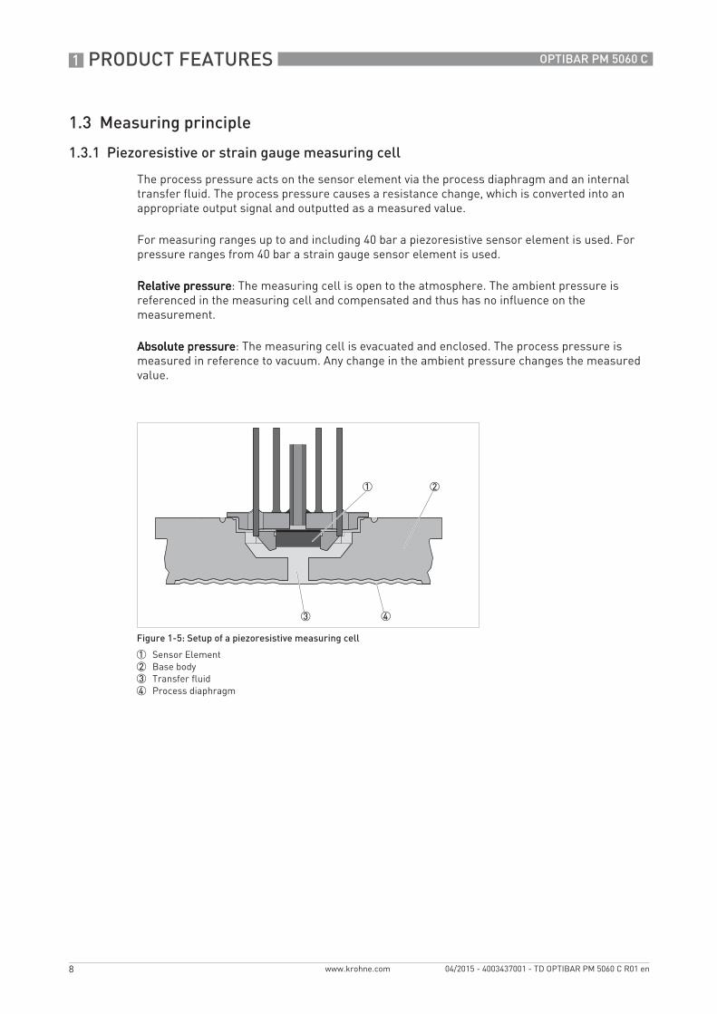
The process pressure acts on the sensor element via the process diaphragm and an internal transfer fluid. The process pressure causes a resistance change, which is converted into an appropriate output signal and outputted as a measured value.
For measuring ranges up to and including 40 bar a piezoresistive sensor element is used. For pressure ranges from 40 bar a strain gauge sensor element is used.
Relative pressureRelative pressureRelative pressureRelative pressure: The measuring cell is open to the atmosphere. The ambient pressure is referenced in the measuring cell and compensated and thus has no influence on the measurement.
Absolute pressureAbsolute pressureAbsolute pressureAbsolute pressure: The measuring cell is evacuated and enclosed. The process pressure is measured in reference to vacuum. Any change in the ambient pressure changes the measured value.
Figure 1-5: Setup of a piezoresistive measuring cell
1 Sensor Element2 Base body3 Transfer fluid4 Process diaphragm
TD_OPTIBAR_PM_5060_en_150423_TD_OPTIBAR_PM_5060_R01.book Page 8 Thursday, April 23, 2015 10:45 AM

PRODUCT FEATURES 1
9
OPTIBAR PM 5060 C
www.krohne.com04/2015 - 4003437001 - TD OPTIBAR PM 5060 C R01 en
1.3.2 Metallic - ceramic measuring cell
For small measuring ranges or higher temperature ranges, the measurement unit is the ceramic capacitive measuring cell. This consists of a special temperature compensating isolating diaphragm system.
Figure 1-6: Setup of metallic-ceramic measuring cell
1 Process diaphragm2 Isolating liquid3 FeNi adapter4 Metallic - ceramic measuring cell
TD_OPTIBAR_PM_5060_en_150423_TD_OPTIBAR_PM_5060_R01.book Page 9 Thursday, April 23, 2015 10:45 AM
2 TECHNICAL DATA
10
OPTIBAR PM 5060 C
www.krohne.com 04/2015 - 4003437001 - TD OPTIBAR PM 5060 C R01 en
Technical data
2.1 Technical data
• The following data is provided for general applications. If you require data that is more relevant to your specific application, please contact us or your local sales office.
• Additional information (certificates, special tools, software,...) and complete product documentation can be downloaded free of charge from the website (Downloadcenter).
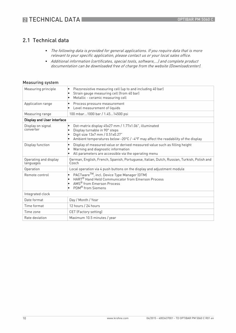
Measuring systemMeasuring principle • Piezoresistive measuring cell (up to and including 40 bar)
• Strain gauge measuring cell (from 40 bar)• Metallic - ceramic measuring cell
Application range • Process pressure measurement• Level measurement of liquids
Measuring range 100 mbar...1000 bar / 1.45...14500 psi
Display and User interfaceDisplay and User interfaceDisplay and User interfaceDisplay and User interface
Display on signal converter
• Dot-matrix display 45x27 mm / 1.77x1.06", illuminated• Display turnable in 90° steps• Digit size 13x7 mm / 0.51x0.27"• Ambient temperatures below -20°C / -4°F may affect the readability of the display
Display function • Display of measured value or derived measured value such as filling height• Warning and diagnostic information• All parameters are accessible via the operating menu
Operating and display languages
German, English, French, Spanish, Portuguese, Italian, Dutch, Russian, Turkish, Polish and Czech
Operation Local operation via 4 push buttons on the display and adjustment module
Remote control • PACTwareTM, incl. Device Type Manager (DTM)• HART® Hand Held Communicator from Emerson Process• AMS® from Emerson Process• PDM® from Siemens
Integrated clock
Date format Day / Month / Year
Time format 12 hours / 24 hours
Time zone CET (Factory setting)
Rate deviation Maximum 10.5 minutes / year
TD_OPTIBAR_PM_5060_en_150423_TD_OPTIBAR_PM_5060_R01.book Page 10 Thursday, April 23, 2015 10:45 AM

TECHNICAL DATA 2
11
OPTIBAR PM 5060 C
www.krohne.com04/2015 - 4003437001 - TD OPTIBAR PM 5060 C R01 en
Measuring accuracy Process pressureProcess pressureProcess pressureProcess pressure
Reference conditions acc. to DIN 61298-1
• Ambient temperature (constant): +18...+30°C / +64...+86°F• Relative humidity (constant): 45...75%• Ambient pressure (constant): 860...1060 mbar / 12.5...15.4 psi• Measuring accuracy according to IEC 61298-2 (terminal based)• Curve characteristic: linear• Vertical mounting position, measuring diaphragm pointing down• Effect of mounting position (piezoresistive or strain gauge measuring cell): dependent on
process connection and diaphragm seals • Effect of mounting position (metallic - ceramic measuring cell): < 5 mbar / 0.5 kPa /
0.07 psig• Deviation at current output due to strong, high-frequency electromagnetic fields within
the scope of EN 61326 (<± 150 µA)
Reference accuracyacc. to DIN EN 60770
Applies to the digital interfaces (HART®, Profibus PA, Foundation Fieldbus) as well as for the analogue 4…20 mA current output and refers to the set measuring span. Turn down (TD) is the relation of nominal range/set measuring span.[% of the set span]
Accuracy class 0.075% 0.10% 0.20%
TD of 1:1 to 5:1 < ±0.075% < ±0.10% < ±0.20%
TD > 5:1 < ±0.015% x TD < ±0.02% x TD < ±0.04% x TD
Effect of ambient or medium temperature
Ambient temperature effect on zero and span in relation to the set measuring span. Applies to the digital interfaces (HART®, Profibus PA, Foundation Fieldbus) as well as for the analogue 4…20 mA current output.[% of the set span]
Piezoresistive or strain gauge measuring cellPiezoresistive or strain gauge measuring cellPiezoresistive or strain gauge measuring cellPiezoresistive or strain gauge measuring cell
Turn Down In the compensated temperature range 10…+70°C / +50…+158°F
Outside the compensated temperature range
TD 1:1 < ±0.05% per 10K typ. < ±0.05% per 10K
TD to 5:1 < ±0.10% per 10K -
TD to 10:1 < ±0.15% per 10K -
Metallic - ceramic measuring cellMetallic - ceramic measuring cellMetallic - ceramic measuring cellMetallic - ceramic measuring cell
Ambient or medium temperature
Accuracy class 0.10% Accuracy class 0.20%
-40...0°C / -40...+32°F < ±0.375 + 0.375 x TD < ±0.65 + 0.65 x TD
0...100°C / +32...+212°F < ±0.075 + 0.075 x TD < ±0.20 + 0.20 x TD
100...120°C / +212...+248°F < ±0.125 + 0.125 x TD < ±0.25 + 0.25 x TD
Effect of mounting position
A position-dependent zero offset can be corrected.
≤0.1 mbar per 10° inclination
Long-term stabilityacc. to DIN 16086and IEC 60770-1
Applies to the digital interfaces (HART®, Profibus PA, Foundation Fieldbus) as well as for the analogue 4…20 mA current output. [% of URL]
Time period Piezoresistive or strain gauge measuring cell
Metallic - ceramic measuring cell
1 year <0.1% x TD <0.05% x TD
5 years <0.1% x TD
10 years <0.2% x TD
Dynamic output behaviour These parameters depend on the fill fluid, temperature and, if applicable, the diaphragm seal.
TD_OPTIBAR_PM_5060_en_150423_TD_OPTIBAR_PM_5060_R01.book Page 11 Thursday, April 23, 2015 10:45 AM

2 TECHNICAL DATA
12
OPTIBAR PM 5060 C
www.krohne.com 04/2015 - 4003437001 - TD OPTIBAR PM 5060 C R01 en
Damping 63% of the input variable 0…999 seconds, adjustable in 0.1 second steps.
Operating conditionsTemperatureTemperatureTemperatureTemperature
Version Ambient temperature Storage and transport temperature
Standard version -40...+80°C / -40...+176°F -60...+80°C / -76...+176°F
IP66 / IP68 version(1 bar / 14.5 psi)
-20...+80°C / -4...+176°F -20...+80°C / -4...+176°F
IP68 version (25 bar / 362 psi), connection cable PUR
-20...+80°C / -4...+176°F -20...+80°C / -4...+176°F
IP68 version (25 bar / 362 psi), connection cable PE
-20...+60°C / -4...+14°F -20...+60°C / -4...+140°F
Temperature deratingTemperature deratingTemperature deratingTemperature derating metallic - ceramic measuring cell
Version Medium temperature Maximum ambient temperature
+150°C / +302°F +110°C / +230°F +80°C / +176°F
+150°C / +302°F +60°C / +140°F
+180°C / +356°F +150°C / +302°F +80°C / +176°F
+180°C / +356°F +65°C / +149°F
+200°C / +392°F +160°C / +320°F +80°C / +176°F
+200°C / +392°F +65°C / +149°F
Further operating conditionsIngress protection acc. to IEC 529 / EN 60529Ingress protection acc. to IEC 529 / EN 60529Ingress protection acc. to IEC 529 / EN 60529Ingress protection acc. to IEC 529 / EN 60529
Plastic (PBT) Single chamber IP66 / IP67 NEMA 6P
Double chamber IP66 / IP67 NEMA 6P
Aluminium Single chamber IP66 / IP67 NEMA 6P
IP68 (1 bar / 14.5 psi) -
Double chamber IP66 / IP67 NEMA 6P
Stainless steel (electro-polished)
Single chamber IP69K -
Single chamber IP66 / IP67 NEMA 6P
Stainless steel (precision casting)
Single chamber IP66 / IP67 NEMA 6P
IP68 (1 bar / 14.5 psi) -
Double chamber IP66 / IP67 NEMA 6P
Stainless steel Sensor for external housing IP68 (25 bar / 362.6 psi) -
VibrationVibrationVibrationVibration
Reference conditions Single chamber housing, aluminium
Vibration resistanceacc. to EN 60068-2-6
4 g at 5...200 Hz
Shock resistantaccording to EN 60068-2-27
100 g, 6 ms (mechanical shock)
TD_OPTIBAR_PM_5060_en_150423_TD_OPTIBAR_PM_5060_R01.book Page 12 Thursday, April 23, 2015 10:45 AM

TECHNICAL DATA 2
13
OPTIBAR PM 5060 C
www.krohne.com04/2015 - 4003437001 - TD OPTIBAR PM 5060 C R01 en
MaterialsGasketsGasketsGasketsGaskets
Sealing Standard version Version with extended temperature range
Version for oxygen application
Without sealing (for process connection acc. to EN 837)
-40...+105°C / -40...+221°F - -40...+60°C / -40...+140°F
FKM (VP2/A) -20...+105°C / -4...+221°F -20...+150°C / -4...+302°F -20...+60°C / -4...+140°F
EPDM (A+P 75, 5/KW75F) -30...+105°C / -22...+221°F -30...+150°C / -22...+302°F -30...+60°C / -22...+140°F
FFKM (Perlast® G75S) -15...+105°C / +5...+221°F -15...+150°C / +5...+302°F -15...+60°C / +5...+140°F
FEPM (Fluoraz® SD 890) -5...+105°C / +23...+221°F - -5...+60°C / +23...+140°F
Wetted parts (piezoresistive or strain gauge measuring cell)Wetted parts (piezoresistive or strain gauge measuring cell)Wetted parts (piezoresistive or strain gauge measuring cell)Wetted parts (piezoresistive or strain gauge measuring cell)
Process connection 316 L / 1.4404
Diaphragm 316 L / 1.4404
Diaphragm for measuring range from 100 bar, non-flush version
Elgiloy® 2.4711
Gasket process connection G1/2 (EN 837)
Thread G1/2 (EN 837) Aramid fibres, bound with NBR
Thread G1 1/2 (DIN 3852-A) Aramid fibres, bound with NBR
M44 x 1.25 (DIN 13), M30 x 1.5 FKM, FFKM and EPDM
FKM (VP2/A, A+P 70.16), EPDM (A+P 75.5/KW75F), FFKM (Perlast® G75S), FEPM (Fluoraz® SD890
Wetted parts (metal/ceramic measuring cell)Wetted parts (metal/ceramic measuring cell)Wetted parts (metal/ceramic measuring cell)Wetted parts (metal/ceramic measuring cell)
Process connection 316 L / 1.4404
Diaphragm Alloy C-276, optional: gold coated 20 μ, gold/rhodium coated 5 μ/1 μ
Gasket process connection G1 1/2 (DIN 3852-A)
Klingersil C-4400
M44 x 1.25 (DIN 13) FKM, FFKM, EPDM
TD_OPTIBAR_PM_5060_en_150423_TD_OPTIBAR_PM_5060_R01.book Page 13 Thursday, April 23, 2015 10:45 AM

2 TECHNICAL DATA
14
OPTIBAR PM 5060 C
www.krohne.com 04/2015 - 4003437001 - TD OPTIBAR PM 5060 C R01 en
Materials for food applicationsMaterials for food applicationsMaterials for food applicationsMaterials for food applications
Surface quality
Aseptic connections Ra< 0.8 µm
Non-wetted partsNon-wetted partsNon-wetted partsNon-wetted parts
Electronics housing Plastic PBT (Polyester), powder coated die-cast aluminium, 316 L / 1.4404
External housing Plastic PBT (polyester) and 316 L / 1.4404
Base, wall mount external housing
Plastic PBT (polyester) and 316 L / 1.4404
Gasket between base and wall mount
EPDM (permanently attached)
Housing cover sealing ring
Silicone (aluminium or plastic housing), NBR (stainless steel housing)
Inspection window in housing cover (display, adjustment module)
Polycarbonate (UL746-C listed)
Ground terminal 316 Ti, 316 L / 1.4404
Connection cable, master and slave sensor
PE and PUR
Nameplate carrier on connecting cable
PE hard
Connection cable for IP68 (1 bar) version
PE
Process connectionThread from G1/2 and 1/2-14 NPT (female)
Flanges from DN 25 (DIN) / 1" (ASME)
Flanges with extension from DN 25 (DIN) / 1" (ASME)
Internal transfer fluid (piezoresistive or strain gauge measuring cell)
Pressure port with inner diaphragm• Silicone oil ≤ 40 bar / 580 psi• Halocarbon oil for oxygen applications ≤ 40 bar / 580 psi • Dry measuring cell (without fill fluid) for pressure ranges ≥ 60 bar / 870 psi
Pressure ports with flush diaphragm• Synthetic oil (Neobee) up to 250 bar (FDA-listed for the food industry)• Silicone oil for G1/2" and G1" process connections (LU, P6, C5)
Other connections ISO 2852 / DIN 32676, DIN 11851, Neumo BioConnect / BioControl, Varivent, DRD, SMS and PMC
Tightening torquesTightening torquesTightening torquesTightening torques
Maximum tightening torques for NPT cable gland and conduit pipe
Plastic housing 10 Nm / 7.4 ft lb
Aluminium housing 50 Nm / 37 ft lb
Stainless steel housing 50 Nm / 37 ft lb
TD_OPTIBAR_PM_5060_en_150423_TD_OPTIBAR_PM_5060_R01.book Page 14 Thursday, April 23, 2015 10:45 AM

TECHNICAL DATA 2
15
OPTIBAR PM 5060 C
www.krohne.com04/2015 - 4003437001 - TD OPTIBAR PM 5060 C R01 en
Electrical connectionsMechanical - StandardMechanical - StandardMechanical - StandardMechanical - Standard
Cable gland M20 x 1.5 mm
cable diameter 5...9 mm / 0.20...0.35"6...12 mm / 0.24...0.47"10...14 mm / 0.39...0.55"
Cable entry Blind plug: M20 x 1.5 mm, 1/2-14 NPT
Closing cap: M20 x 1.5 mm, 1/2-14 NPT
Connector option: M12 x 1, Harting HAN 7D,8D, 7/8" FF
Wire cross-section Solid wire with cords: 0.2 mm...2.5 mm2 / AWG 24...14
Cord with wire end sleeve: 0.2 mm...1.5 mm2 / AWG 4...16
Mechanical - IP66 / IP68 (1 bar)Mechanical - IP66 / IP68 (1 bar)Mechanical - IP66 / IP68 (1 bar)Mechanical - IP66 / IP68 (1 bar)
Connection cable
Construction Four wires, one pressure compensation capillary, one suspension cable, screen braiding, metal foil and cable jacket
Wire cross-section 0.5 mm2 / AWG 20
Wire resistance < 0.036 Ω/m
Tensile strength < 1200 N / 270 lbf
Standard length 5 m / 16.40 ft
Max. length 25 m / 82.02 ft
Min. bending radius 25 mm / 0.98" at 25°C / 77°F
Diameter ca. 8 mm / 0.31"
Colour Non-Ex version: black
Ex version: blue (optional)
Mechanical - IP68 (25 bar)Mechanical - IP68 (25 bar)Mechanical - IP68 (25 bar)Mechanical - IP68 (25 bar)
Connecting cable between IP68 device and external housing
Construction Four wires, one pressure compensation capillary, one suspension cable, screen braiding, metal foil and cable jacket
Wire cross-section 0.5 mm2 / AWG 20
Wire resistance < 0.036 Ω/m / 0.011 Ω/ft
Standard length 5 m / 16.40 ft
Max. length 25 m / 82.02 ft
Min. bending radius 25 mm / 0.98" at 25°C / 77°F
Diameter ca. 8 mm / 0.31"
Colour Blue
Cable entry / Connector
External housing 1 x cable gland M20 x 1.5 (cable Ø 5...9 mm), 1 x blind plug M20 x 1.5 or
1 x connector (depending on version), 1 x blind plug M20 x 1.5
Spring load terminals for wire cross-section up to
2.5 mm2 / AWG 14
TD_OPTIBAR_PM_5060_en_150423_TD_OPTIBAR_PM_5060_R01.book Page 15 Thursday, April 23, 2015 10:45 AM
2 TECHNICAL DATA
16
OPTIBAR PM 5060 C
www.krohne.com 04/2015 - 4003437001 - TD OPTIBAR PM 5060 C R01 en
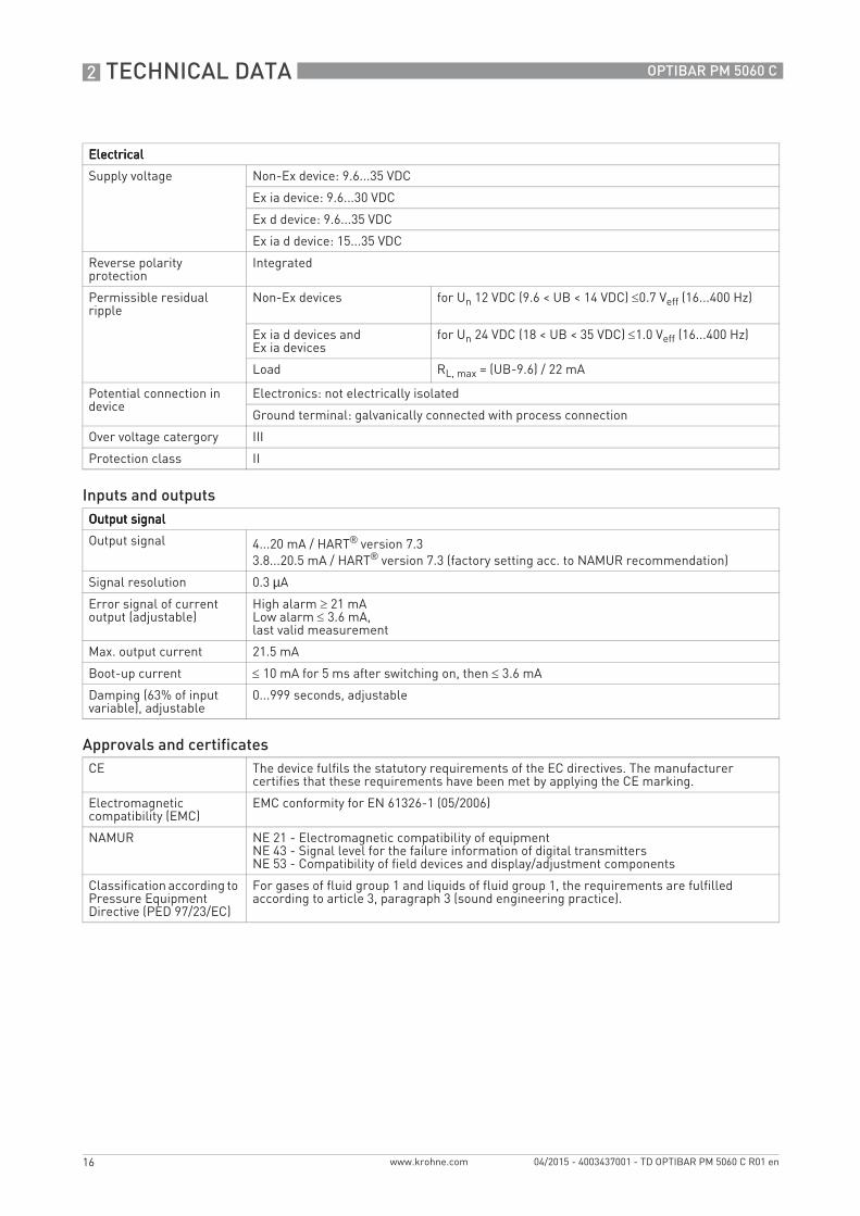
ElectricalElectricalElectricalElectrical
Supply voltage Non-Ex device: 9.6...35 VDC
Ex ia device: 9.6...30 VDC
Ex d device: 9.6...35 VDC
Ex ia d device: 15...35 VDC
Reverse polarity protection
Integrated
Permissible residual ripple
Non-Ex devices for Un 12 VDC (9.6 < UB < 14 VDC) ≤0.7 Veff (16...400 Hz)
Ex ia d devices and Ex ia devices
for Un 24 VDC (18 < UB < 35 VDC) ≤1.0 Veff (16...400 Hz)
Load RL, max = (UB-9.6) / 22 mA
Potential connection in device
Electronics: not electrically isolated
Ground terminal: galvanically connected with process connection
Over voltage catergory III
Protection class II
Inputs and outputsOutput signalOutput signalOutput signalOutput signal
Output signal 4...20 mA / HART® version 7.33.8...20.5 mA / HART® version 7.3 (factory setting acc. to NAMUR recommendation)
Signal resolution 0.3 µA
Error signal of current output (adjustable)
High alarm ≥ 21 mALow alarm ≤ 3.6 mA,last valid measurement
Max. output current 21.5 mA
Boot-up current ≤ 10 mA for 5 ms after switching on, then ≤ 3.6 mA
Damping (63% of input variable), adjustable
0...999 seconds, adjustable
Approvals and certificatesCE The device fulfils the statutory requirements of the EC directives. The manufacturer
certifies that these requirements have been met by applying the CE marking.
Electromagnetic compatibility (EMC)
EMC conformity for EN 61326-1 (05/2006)
NAMUR NE 21 - Electromagnetic compatibility of equipmentNE 43 - Signal level for the failure information of digital transmittersNE 53 - Compatibility of field devices and display/adjustment components
Classification according to Pressure Equipment Directive (PED 97/23/EC)
For gases of fluid group 1 and liquids of fluid group 1, the requirements are fulfilled according to article 3, paragraph 3 (sound engineering practice).
TD_OPTIBAR_PM_5060_en_150423_TD_OPTIBAR_PM_5060_R01.book Page 16 Thursday, April 23, 2015 10:45 AM

TECHNICAL DATA 2
17
OPTIBAR PM 5060 C
www.krohne.com04/2015 - 4003437001 - TD OPTIBAR PM 5060 C R01 en
2.2 Dimensions and weights
Figure 2-1: Aluminium housing
1 Single chamber2 Double chamber
Dimension [mm] Dimension [inch]
a 116 4.57
b 86 3.39
c 116 4.57
d 87 3.43
e 86 3.39
f 120 4.72
With integrated display and adjustment module the height of the housing increases by 9 mm / 0.35 inch.
Housing version Weight [kg] Weight [lb]
Single chamber, aluminium 0.83 1.84
Double chamber, aluminium 1.24 2.73
TD_OPTIBAR_PM_5060_en_150423_TD_OPTIBAR_PM_5060_R01.book Page 17 Thursday, April 23, 2015 10:45 AM

2 TECHNICAL DATA
18
OPTIBAR PM 5060 C
www.krohne.com 04/2015 - 4003437001 - TD OPTIBAR PM 5060 C R01 en
Figure 2-2: Aluminium housing in IP66 / IP68 version (1 bar)
1 Single chamber2 Double chamber
Dimension [mm] Dimension [inch]
a 150 5.91
b 86 3.39
c 116 4.57
d 105 4.13
e 120 4.72
f M20 x 1.5
g M20 x 1,5 / 1/2-14 NPT
h M16 x 1.5
g
h
e
f f
With integrated display and adjustment module the height of the housing increases by 9 mm / 0.35 inch.
TD_OPTIBAR_PM_5060_en_150423_TD_OPTIBAR_PM_5060_R01.book Page 18 Thursday, April 23, 2015 10:45 AM
TECHNICAL DATA 2
19
OPTIBAR PM 5060 C
www.krohne.com04/2015 - 4003437001 - TD OPTIBAR PM 5060 C R01 en
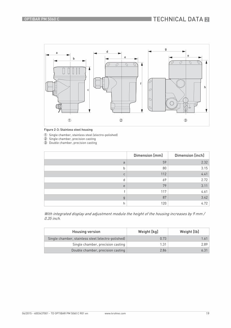
Figure 2-3: Stainless steel housing
1 Single chamber, stainless steel (electro-polished)2 Single chamber, precision casting3 Double chamber, precision casting
Dimension [mm] Dimension [inch]
a 59 2.32
b 80 3.15
c 112 4.41
d 69 2.72
e 79 3.11
f 117 4.61
g 87 3.42
h 120 4.72
With integrated display and adjustment module the height of the housing increases by 9 mm / 0.35 inch.
Housing version Weight [kg] Weight [lb]
Single chamber, stainless steel (electro-polished) 0.73 1.61
Single chamber, precision casting 1.31 2.89
Double chamber, precision casting 2.86 6.31
TD_OPTIBAR_PM_5060_en_150423_TD_OPTIBAR_PM_5060_R01.book Page 19 Thursday, April 23, 2015 10:45 AM
2 TECHNICAL DATA
20
OPTIBAR PM 5060 C
www.krohne.com 04/2015 - 4003437001 - TD OPTIBAR PM 5060 C R01 en
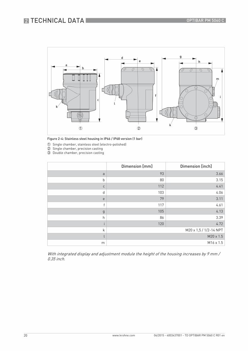
Figure 2-4: Stainless steel housing in IP66 / IP68 version (1 bar)
1 Single chamber, stainless steel (electro-polished)2 Single chamber, precision casting3 Double chamber, precision casting
Dimension [mm] Dimension [inch]
a 93 3.66
b 80 3.15
c 112 4.41
d 103 4.06
e 79 3.11
f 117 4.61
g 105 4.13
h 86 3.39
i 120 4.72
k M20 x 1,5 / 1/2-14 NPT
l M20 x 1.5
m M16 x 1.5
e
f
g
h
i
With integrated display and adjustment module the height of the housing increases by 9 mm / 0.35 inch.
TD_OPTIBAR_PM_5060_en_150423_TD_OPTIBAR_PM_5060_R01.book Page 20 Thursday, April 23, 2015 10:45 AM

TECHNICAL DATA 2
21
OPTIBAR PM 5060 C
www.krohne.com04/2015 - 4003437001 - TD OPTIBAR PM 5060 C R01 en
Figure 2-5: Stainless steel (electro-polished) in IP69K version
Dimension [mm] Dimension [inch]
a 59 2.32
b 80 3.15
c 104 4.10
With integrated display and adjustment module the height of the housing increases by 9 mm / 0.35 inch.
Housing version Weight [kg] Weight [lb]
Single chamber, stainless steel (electro-polished) 0.73 1.61
TD_OPTIBAR_PM_5060_en_150423_TD_OPTIBAR_PM_5060_R01.book Page 21 Thursday, April 23, 2015 10:45 AM

2 TECHNICAL DATA
22
OPTIBAR PM 5060 C
www.krohne.com 04/2015 - 4003437001 - TD OPTIBAR PM 5060 C R01 en
Figure 2-6: Plastic housing
1 Single chamber2 Double chamber
Dimension [mm] Dimension [inch]
a 69 2.72
b 79 3.11
c 112 4.41
d 84 3.31
e 79 3.11
f 112 4.41
With integrated display and adjustment module the height of the housing increases by 9 mm / 0.35 inch.
Housing version Weight [kg] Weight [lb]
Single chamber, plastic 0.40 0.88
Double chamber, plastic 0.51 1.13
TD_OPTIBAR_PM_5060_en_150423_TD_OPTIBAR_PM_5060_R01.book Page 22 Thursday, April 23, 2015 10:45 AM
TECHNICAL DATA 2
23
OPTIBAR PM 5060 C
www.krohne.com04/2015 - 4003437001 - TD OPTIBAR PM 5060 C R01 en
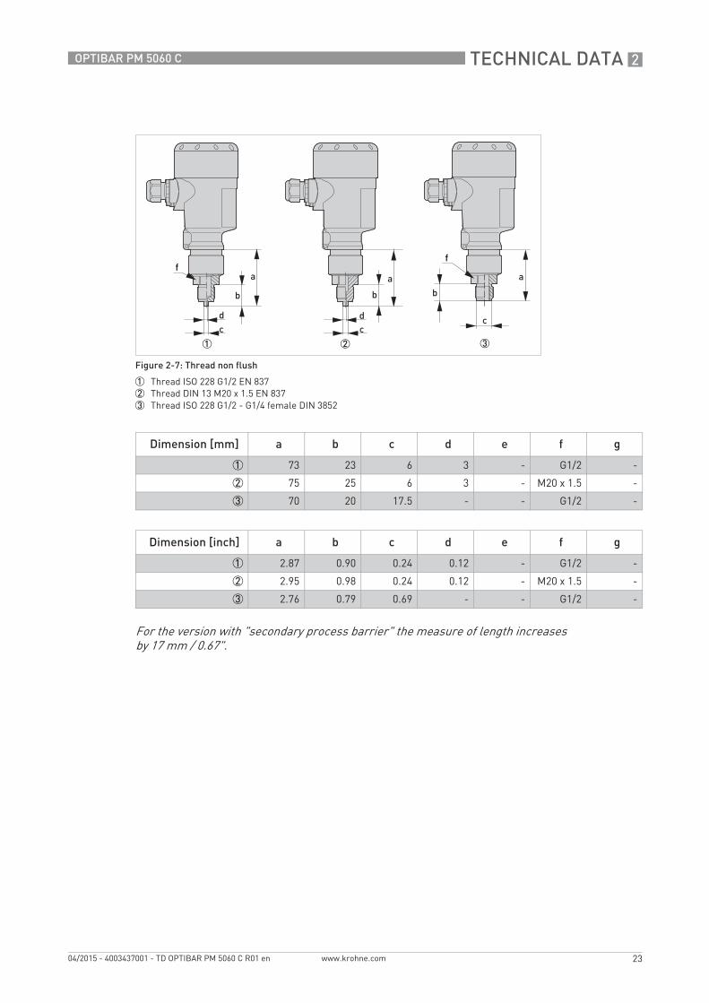
Figure 2-7: Thread non flush
1 Thread ISO 228 G1/2 EN 8372 Thread DIN 13 M20 x 1.5 EN 8373 Thread ISO 228 G1/2 - G1/4 female DIN 3852
Dimension [mm] a b c d e f g
1 73 23 6 3 - G1/2 -
2 75 25 6 3 - M20 x 1.5 -
3 70 20 17.5 - - G1/2 -
Dimension [inch] a b c d e f g
1 2.87 0.90 0.24 0.12 - G1/2 -
2 2.95 0.98 0.24 0.12 - M20 x 1.5 -
3 2.76 0.79 0.69 - - G1/2 -
ff
For the version with "secondary process barrier" the measure of length increases by 17 mm / 0.67".
TD_OPTIBAR_PM_5060_en_150423_TD_OPTIBAR_PM_5060_R01.book Page 23 Thursday, April 23, 2015 10:45 AM
2 TECHNICAL DATA
24
OPTIBAR PM 5060 C
www.krohne.com 04/2015 - 4003437001 - TD OPTIBAR PM 5060 C R01 en
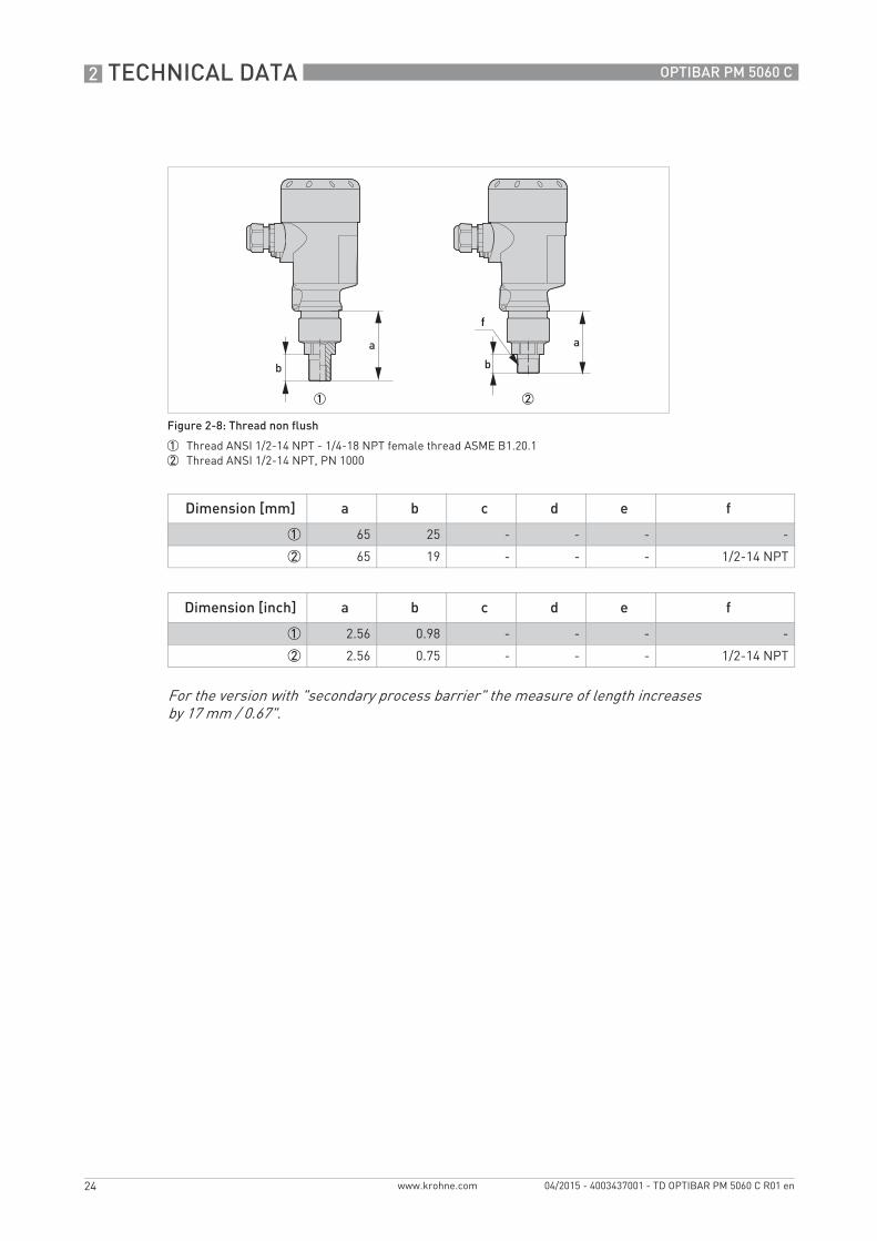
Figure 2-8: Thread non flush
1 Thread ANSI 1/2-14 NPT - 1/4-18 NPT female thread ASME B1.20.12 Thread ANSI 1/2-14 NPT, PN 1000
Dimension [mm] a b c d e f
1 65 25 - - - -
2 65 19 - - - 1/2-14 NPT
Dimension [inch] a b c d e f
1 2.56 0.98 - - - -
2 2.56 0.75 - - - 1/2-14 NPT
f
For the version with "secondary process barrier" the measure of length increasesby 17 mm / 0.67".
TD_OPTIBAR_PM_5060_en_150423_TD_OPTIBAR_PM_5060_R01.book Page 24 Thursday, April 23, 2015 10:45 AM
TECHNICAL DATA 2
25
OPTIBAR PM 5060 C
www.krohne.com04/2015 - 4003437001 - TD OPTIBAR PM 5060 C R01 en
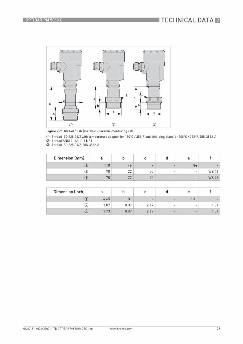
Figure 2-9: Thread flush (metallic - ceramic measuring cell)
1 Thread ISO 228 G1/2 with temperature adapter for 180°C / 356°F and shielding plate for 200°C / 392°F, DIN 3852-A2 Thread ANSI 1 1/2-11.5 NPT 3 Thread ISO 228 G1/2, DIN 3852-A
Dimension [mm] a b c d e f
1 118 46 - - 84 -
2 78 22 55 - - WS 46
3 78 22 55 - - WS 46
Dimension [inch] a b c d e f
1 4.65 1.81 - - 3.31 -
2 3.07 0.87 2.17 - - 1.81
3 1.73 0.87 2.17 - - 1.81
e
f f
TD_OPTIBAR_PM_5060_en_150423_TD_OPTIBAR_PM_5060_R01.book Page 25 Thursday, April 23, 2015 10:45 AM
2 TECHNICAL DATA
26
OPTIBAR PM 5060 C
www.krohne.com 04/2015 - 4003437001 - TD OPTIBAR PM 5060 C R01 en
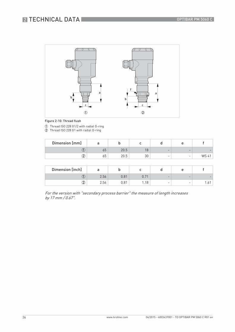
Figure 2-10: Thread flush
1 Thread ISO 228 G1/2 with radial O-ring2 Thread ISO 228 G1 with radial O-ring
Dimension [mm] a b c d e f
1 65 20.5 18 - - -
2 65 20.5 30 - - WS 41
Dimension [inch] a b c d e f
1 2.56 0.81 0.71 - - -
2 2.56 0.81 1.18 - - 1.61
f
For the version with "secondary process barrier" the measure of length increasesby 17 mm / 0.67".
TD_OPTIBAR_PM_5060_en_150423_TD_OPTIBAR_PM_5060_R01.book Page 26 Thursday, April 23, 2015 10:45 AM

TECHNICAL DATA 2
27
OPTIBAR PM 5060 C
www.krohne.com04/2015 - 4003437001 - TD OPTIBAR PM 5060 C R01 en
Figure 2-11: Hygienic connection 150°C / 302°F
1 Clamp DN50 2" PN16, DIN 32676 / ISO 28522 Hygienic connection with grooved union nut F40 PN253 Varivent N50-40 PN25, 316 L
Dimension [mm] a b c d e f
1 80 - 64 - - -
2 82 - 78 - - -
3 80 - 84 - - -
Dimension [inch] a b c d e f
1 3.15 - 2.52 - - -
2 3.23 - 3.07 - - -
3 3.15 - 3.31 - - -
For the version with a temperature range up to 150°C / 302°F the measure of length increasesby 28 mm / 1.1".
For the version with "secondary process barrier" the measure of length increasesby 17 mm / 0.67".
TD_OPTIBAR_PM_5060_en_150423_TD_OPTIBAR_PM_5060_R01.book Page 27 Thursday, April 23, 2015 10:45 AM
2 TECHNICAL DATA
28
OPTIBAR PM 5060 C
www.krohne.com 04/2015 - 4003437001 - TD OPTIBAR PM 5060 C R01 en
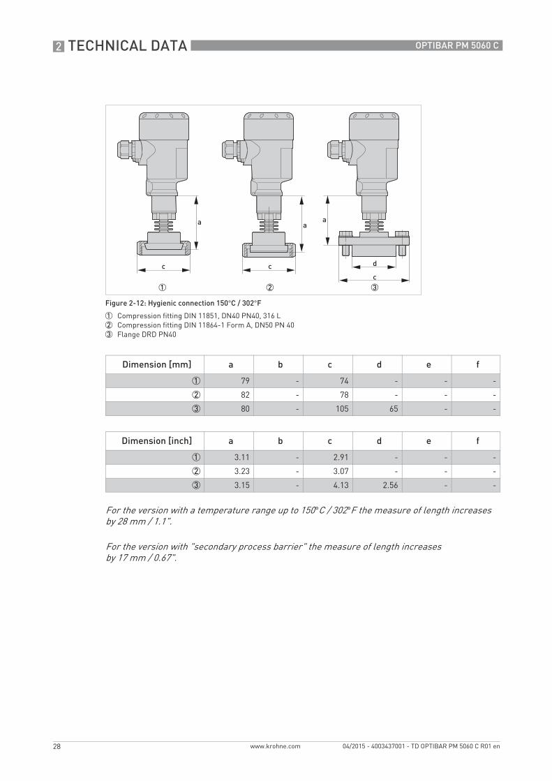
Figure 2-12: Hygienic connection 150°C / 302°F
1 Compression fitting DIN 11851, DN40 PN40, 316 L2 Compression fitting DIN 11864-1 Form A, DN50 PN 403 Flange DRD PN40
Dimension [mm] a b c d e f
1 79 - 74 - - -
2 82 - 78 - - -
3 80 - 105 65 - -
Dimension [inch] a b c d e f
1 3.11 - 2.91 - - -
2 3.23 - 3.07 - - -
3 3.15 - 4.13 2.56 - -
For the version with a temperature range up to 150°C / 302°F the measure of length increasesby 28 mm / 1.1".
For the version with "secondary process barrier" the measure of length increasesby 17 mm / 0.67".
TD_OPTIBAR_PM_5060_en_150423_TD_OPTIBAR_PM_5060_R01.book Page 28 Thursday, April 23, 2015 10:45 AM
TECHNICAL DATA 2
29
OPTIBAR PM 5060 C
www.krohne.com04/2015 - 4003437001 - TD OPTIBAR PM 5060 C R01 en
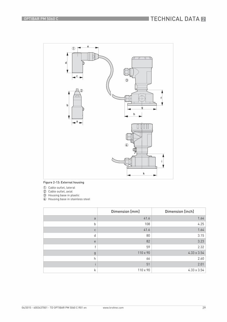
Figure 2-13: External housing
1 Cable outlet, lateral2 Cable outlet, axial3 Housing base in plastic4 Housing base in stainless steel
Dimension [mm] Dimension [inch]
a 41.6 1.64
b 108 4.25
c 41.6 1.64
d 80 3.15
e 82 3.23
f 59 2.32
g 110 x 90 4.33 x 3.54
h 66 2.60
i 51 2.01
k 110 x 90 4.33 x 3.54
e
f
g
h
i
k
TD_OPTIBAR_PM_5060_en_150423_TD_OPTIBAR_PM_5060_R01.book Page 29 Thursday, April 23, 2015 10:45 AM
2 TECHNICAL DATA
30
OPTIBAR PM 5060 C
www.krohne.com 04/2015 - 4003437001 - TD OPTIBAR PM 5060 C R01 en
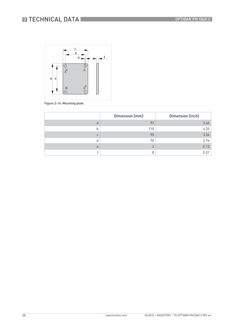
Figure 2-14: Mounting plate
Dimension [mm] Dimension [inch]
a 93 3.66
b 110 4.33
c 90 3.54
d 70 2.76
e 3 0.12
f 8 0.31
e f
TD_OPTIBAR_PM_5060_en_150423_TD_OPTIBAR_PM_5060_R01.book Page 30 Thursday, April 23, 2015 10:45 AM

TECHNICAL DATA 2
31
OPTIBAR PM 5060 C
www.krohne.com04/2015 - 4003437001 - TD OPTIBAR PM 5060 C R01 en
Flange connection acc. to DIN 2501 or ASME B16.5
Figure 2-15: Dimensions - Flange
1 Flange connection acc. to DIN 25012 Flange connection acc. to ASME B16.5
efg
h
i
Dimension [mm] a b c d e f g h i
DN40 PN40 Form C 80 4 x Ø 18 18 3 88 110 150 - -
DN50 PN40 Form C 80 4 x Ø 18 20 3 102 125 165 - -
DN50 PN40 Form Cwith extension
80 4 x Ø 18 20 3 102 125 165 38 10...200
DN80 PN40 Form C 80 8 x Ø 18 24 3 138 180 200 - -
2" Class 150 lb RF 80 4 x Ø 19.1 19.1 3.2 91.9 120.7 152.4 - -
3" Class 150 lb RF 80 8 x Ø 19.1 23.9 3.2 127 152.4 190.5 - -
Dimension [inch] a b c d e f g h i
DN40 PN40 Form C 3.15 4 x Ø 0.71 0.71 0.12 3.46 4.33 5.91 - -
DN50 PN40 Form C 3.15 4 x Ø 0.71 0.79 0.12 4.02 4.92 6.50 - -
DN50 PN40 Form Cwith extension
3.15 4 x Ø 0.71 0.79 0.12 4.02 4.92 6.50 1.5 0.39...7.87
DN80 PN40 Form C 3.15 8 x Ø 0.71 0.95 0.12 5.43 6.30 7.87 - -
2" Class 150 lb RF 3.15 4 x Ø 0.75 0.75 0.13 3.62 4.75 6 - -
3" Class 150 lb RF 3.15 8 x Ø 0.75 0.94 0.13 5 6 7.50 - -
TD_OPTIBAR_PM_5060_en_150423_TD_OPTIBAR_PM_5060_R01.book Page 31 Thursday, April 23, 2015 10:45 AM
2 TECHNICAL DATA
32
OPTIBAR PM 5060 C
www.krohne.com 04/2015 - 4003437001 - TD OPTIBAR PM 5060 C R01 en
2.3 Pressure ranges
2.3.1 Piezoresistive or strain gauge measuring cell
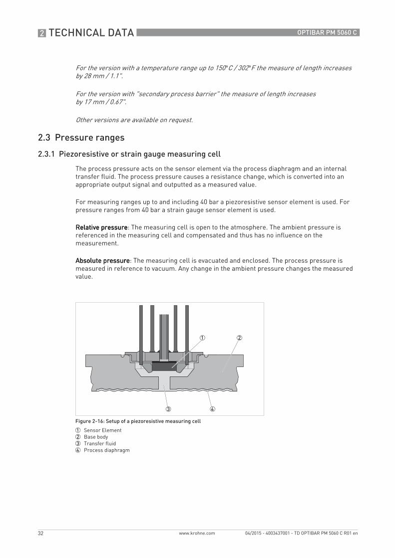
The process pressure acts on the sensor element via the process diaphragm and an internal transfer fluid. The process pressure causes a resistance change, which is converted into an appropriate output signal and outputted as a measured value.
For measuring ranges up to and including 40 bar a piezoresistive sensor element is used. For pressure ranges from 40 bar a strain gauge sensor element is used.
Relative pressureRelative pressureRelative pressureRelative pressure: The measuring cell is open to the atmosphere. The ambient pressure is referenced in the measuring cell and compensated and thus has no influence on the measurement.
Absolute pressureAbsolute pressureAbsolute pressureAbsolute pressure: The measuring cell is evacuated and enclosed. The process pressure is measured in reference to vacuum. Any change in the ambient pressure changes the measured value.
For the version with a temperature range up to 150°C / 302°F the measure of length increasesby 28 mm / 1.1".
For the version with "secondary process barrier" the measure of length increasesby 17 mm / 0.67".
Other versions are available on request.
Figure 2-16: Setup of a piezoresistive measuring cell
1 Sensor Element2 Base body3 Transfer fluid4 Process diaphragm
TD_OPTIBAR_PM_5060_en_150423_TD_OPTIBAR_PM_5060_R01.book Page 32 Thursday, April 23, 2015 10:45 AM
TECHNICAL DATA 2
33
OPTIBAR PM 5060 C
www.krohne.com04/2015 - 4003437001 - TD OPTIBAR PM 5060 C R01 en
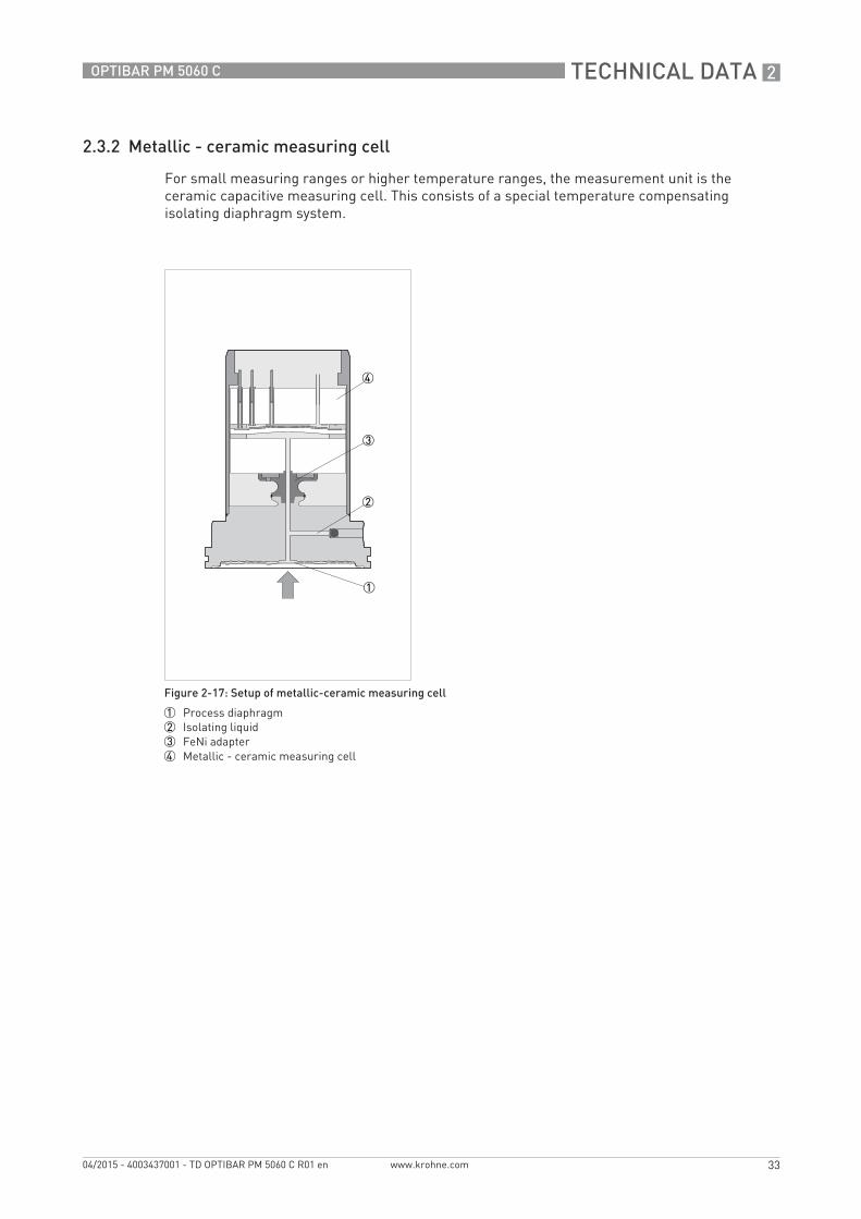
2.3.2 Metallic - ceramic measuring cell
For small measuring ranges or higher temperature ranges, the measurement unit is the ceramic capacitive measuring cell. This consists of a special temperature compensating isolating diaphragm system.
Figure 2-17: Setup of metallic-ceramic measuring cell
1 Process diaphragm2 Isolating liquid3 FeNi adapter4 Metallic - ceramic measuring cell
TD_OPTIBAR_PM_5060_en_150423_TD_OPTIBAR_PM_5060_R01.book Page 33 Thursday, April 23, 2015 10:45 AM
3 INSTALLATION
34
OPTIBAR PM 5060 C
www.krohne.com 04/2015 - 4003437001 - TD OPTIBAR PM 5060 C R01 en
Installation
3.1 Intended use
The OPTIBAR PM 5060 C process pressure transmitter is suitable for measuring the process pressure and level of gases, vapours and liquids. The available measurement ranges and the respective permissible overloads are indicated on the nameplate. For details refer to Technical data on page 10. To observe the intended use, adhere to the following points:
• Observe the instructions in this document.• Comply with the technical specifications (for further information refer to Technical data on
page 10).• Only suitably qualified personnel may install and operate the device.• Observe the generally accepted standards of good practice.
3.2 Installation specifications
The accuracy of the measurement is only guaranteed if the transmitter and accompanying impulse line(s), if any, have been correctly installed. In addition, extreme ambient conditions including large fluctuations in temperature, vibrations and shocks should be kept as far away as possible from the measuring equipment.
For devices used in hazardous areas, additional safety instructions apply.
Responsibility for the use of the measuring devices with regard to suitability, intended use and corrosion resistance of the used materials against the measured fluid lies solely with the operator.
The manufacturer is not liable for any damage resulting from improper use or use for other than the intended purpose.
Observe the relevant directives, ordinances, standards and accident prevention regulations (e.g. VDE/VDI 3512, DIN 19210, VBG, Elex V, etc.).
TD_OPTIBAR_PM_5060_en_150423_TD_OPTIBAR_PM_5060_R01.book Page 34 Thursday, April 23, 2015 10:45 AM

INSTALLATION 3
35
OPTIBAR PM 5060 C
www.krohne.com04/2015 - 4003437001 - TD OPTIBAR PM 5060 C R01 en
3.3 Venting
The ventilation for the electronics housing is assured via a filter element in the vicinity of the cable glands, which is permeable to air but water-absorbent.
In order to ensure effective ventilation, the filter element must be always free of deposits.
Do not use a high-pressure cleaner to clean the housing. The filter element may become damaged and as a result moisture can penetrate into the housing. The exception to this is the IP69K single chamber housing.
1 Single chamber housing, plastic, stainless steel precision casting2 Single chamber housing, aluminium3 Single chamber housing, stainless steel electro-polished4 Double chamber housing, plastic5 Double chamber housing, aluminium6 Single chamber housing IP69k7 Filter element
TD_OPTIBAR_PM_5060_en_150423_TD_OPTIBAR_PM_5060_R01.book Page 35 Thursday, April 23, 2015 10:45 AM
3 INSTALLATION
36
OPTIBAR PM 5060 C
www.krohne.com 04/2015 - 4003437001 - TD OPTIBAR PM 5060 C R01 en
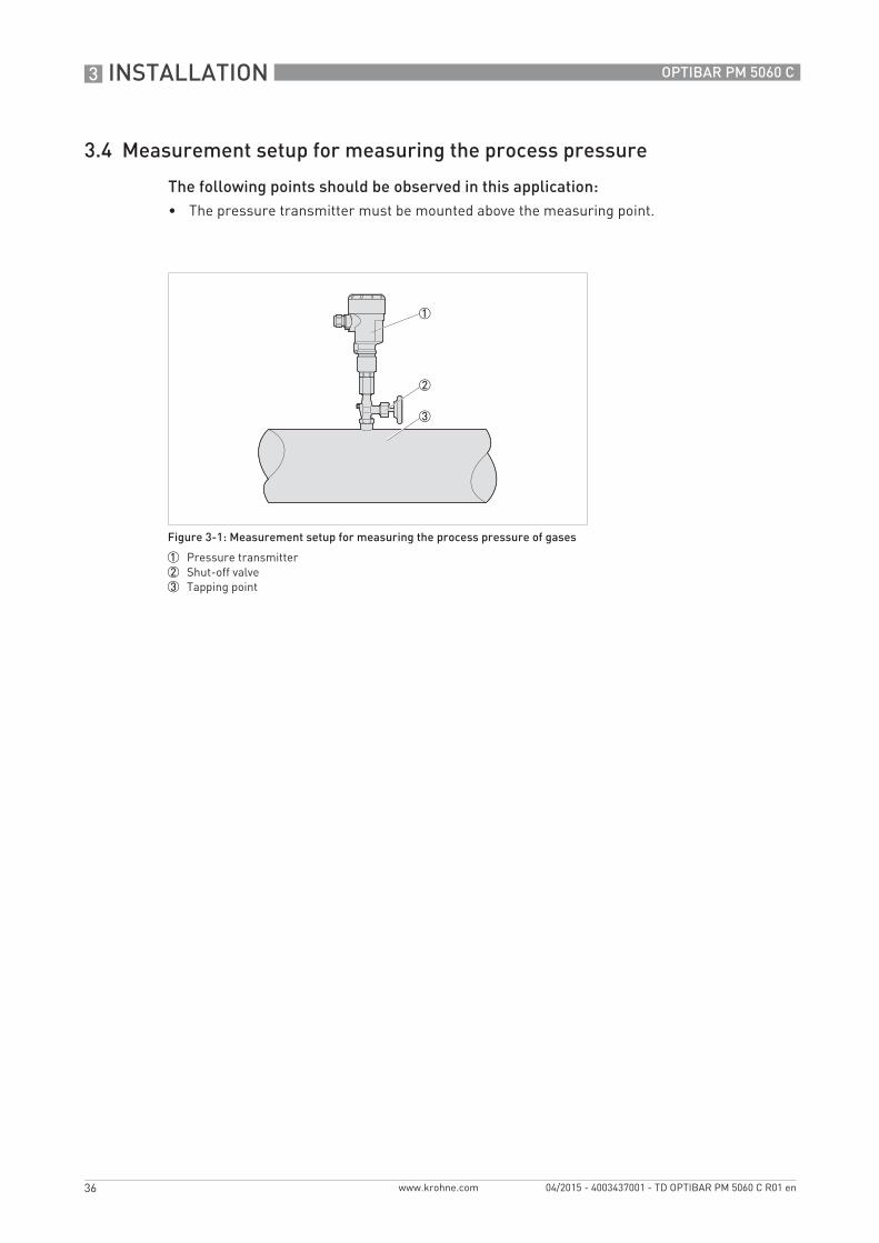
3.4 Measurement setup for measuring the process pressure
The following points should be observed in this application:• The pressure transmitter must be mounted above the measuring point.
Figure 3-1: Measurement setup for measuring the process pressure of gases
1 Pressure transmitter2 Shut-off valve3 Tapping point
TD_OPTIBAR_PM_5060_en_150423_TD_OPTIBAR_PM_5060_R01.book Page 36 Thursday, April 23, 2015 10:45 AM

INSTALLATION 3
37
OPTIBAR PM 5060 C
www.krohne.com04/2015 - 4003437001 - TD OPTIBAR PM 5060 C R01 en
3.5 Measurement setup for measuring steam
The following points should be observed in this application:• The pressure transmitter should be connected via a syphon to protect the measuring cell
from non-permitted high temperatures.• Siphon to be kept free of insulation.• When using superheated steam, the siphon must be filled with water prior to start-up.
Figure 3-2: Measurement setup for measuring steam
1 Pressure transmitter2 Shut-off valve3 Syphon4 Tapping point
TD_OPTIBAR_PM_5060_en_150423_TD_OPTIBAR_PM_5060_R01.book Page 37 Thursday, April 23, 2015 10:45 AM
3 INSTALLATION
38
OPTIBAR PM 5060 C
www.krohne.com 04/2015 - 4003437001 - TD OPTIBAR PM 5060 C R01 en
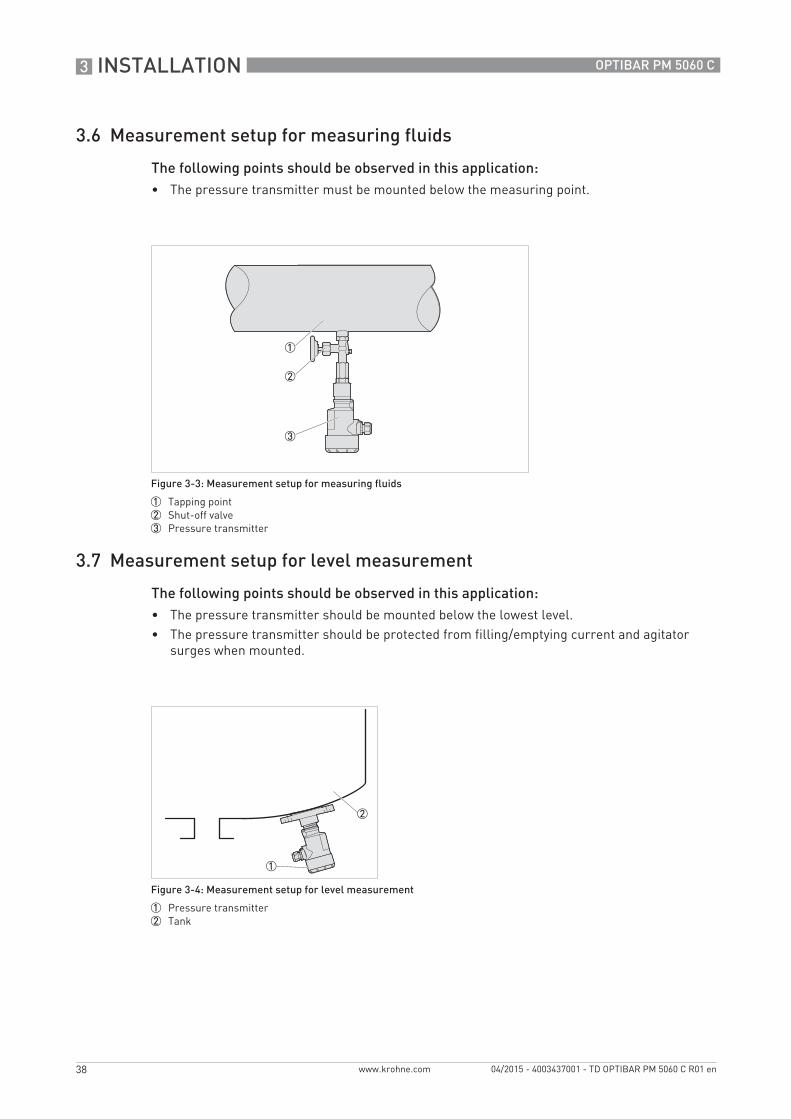
3.6 Measurement setup for measuring fluids
The following points should be observed in this application:• The pressure transmitter must be mounted below the measuring point.
3.7 Measurement setup for level measurement
The following points should be observed in this application:• The pressure transmitter should be mounted below the lowest level.• The pressure transmitter should be protected from filling/emptying current and agitator
surges when mounted.
Figure 3-3: Measurement setup for measuring fluids
1 Tapping point2 Shut-off valve3 Pressure transmitter
Figure 3-4: Measurement setup for level measurement
1 Pressure transmitter2 Tank
TD_OPTIBAR_PM_5060_en_150423_TD_OPTIBAR_PM_5060_R01.book Page 38 Thursday, April 23, 2015 10:45 AM
INSTALLATION 3
39
OPTIBAR PM 5060 C
www.krohne.com04/2015 - 4003437001 - TD OPTIBAR PM 5060 C R01 en
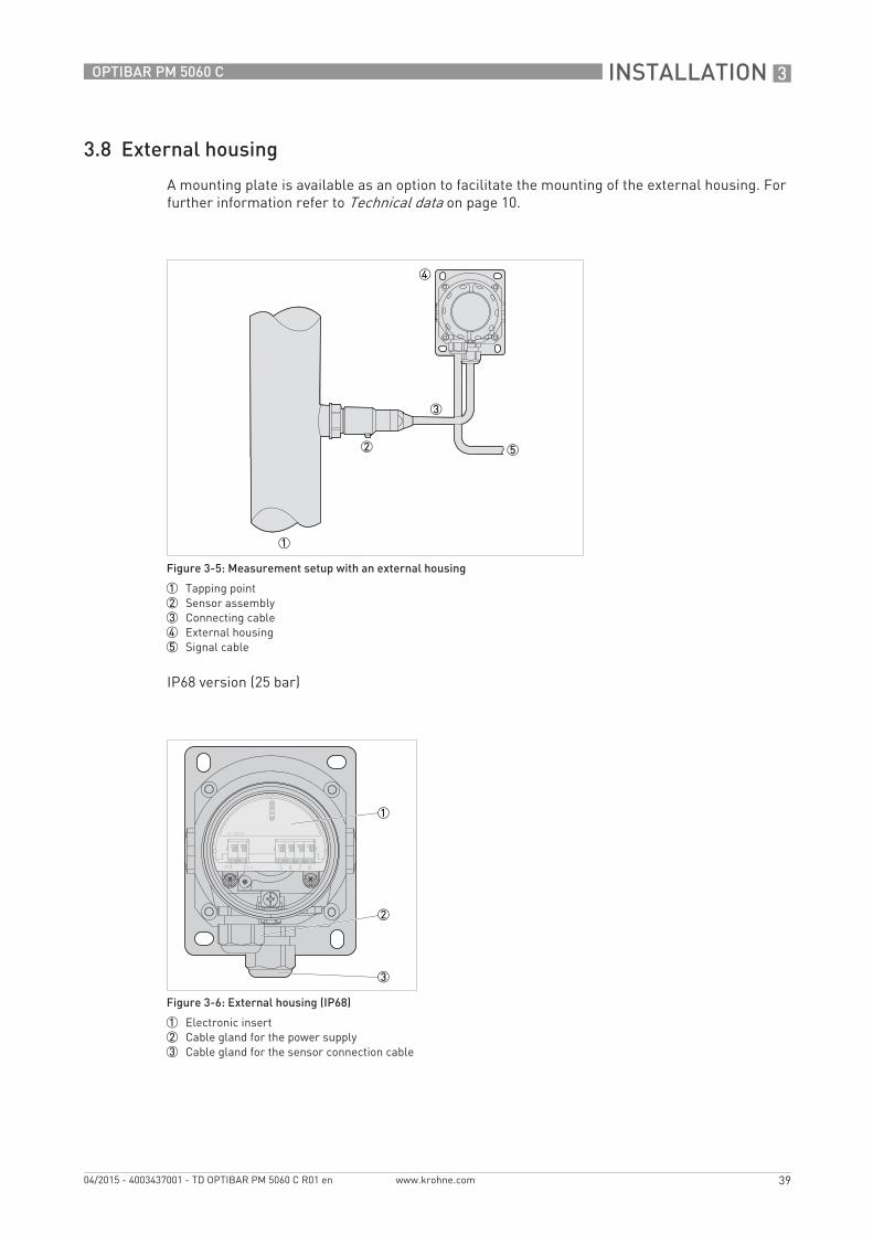
3.8 External housing
A mounting plate is available as an option to facilitate the mounting of the external housing. For further information refer to Technical data on page 10.
IP68 version (25 bar)
Figure 3-5: Measurement setup with an external housing
1 Tapping point2 Sensor assembly3 Connecting cable4 External housing5 Signal cable
Figure 3-6: External housing (IP68)
1 Electronic insert2 Cable gland for the power supply3 Cable gland for the sensor connection cable
TD_OPTIBAR_PM_5060_en_150423_TD_OPTIBAR_PM_5060_R01.book Page 39 Thursday, April 23, 2015 10:45 AM
4 ELECTRICAL CONNECTIONS
40
OPTIBAR PM 5060 C
www.krohne.com 04/2015 - 4003437001 - TD OPTIBAR PM 5060 C R01 en
Electrical connections
4.1 Safety instructions
4.2 Notes for electrical cables
All work on the electrical connections may only be carried out with the power disconnected. Take note of the voltage data on the nameplate!
Observe the national regulations for electrical installations!
Observe without fail the local occupational health and safety regulations. Any work done on the electrical components of the measuring device may only be carried out by properly trained specialists.
Look at the device nameplate to ensure that the device is delivered according to your order. Check for the correct supply voltage printed on the nameplate.
The device must be grounded to a spot in accordance with regulations in order to protect personnel against electric shocks.
Cables may only be connected when the power is switched off! Since the transmitter has no switch-off elements, overcurrent protection devices, lightning protection and/or energy isolating devices must be provided by the customer.
TD_OPTIBAR_PM_5060_en_150423_TD_OPTIBAR_PM_5060_R01.book Page 40 Thursday, April 23, 2015 10:45 AM
ELECTRICAL CONNECTIONS 4
41
OPTIBAR PM 5060 C
www.krohne.com04/2015 - 4003437001 - TD OPTIBAR PM 5060 C R01 en
4.2.1 Requirements for signal cables supplied by the customer
If the signal cable was not ordered, it is to be provided by the customer. The following requirements regarding the electrical specifications of the signal cable must be observed:
Specifications for standard signal cables• Test voltage: ≥ 500 VAC RMS (750 VDC)• Temperature range: -40...+105°C / -40...+221°F• Capacity: ≤ 200 pF/m / 61 pF/ft• Inductance: ≤ 0.7 µH/m / 0.2 µH/ft• Use cable with round cross section.• A cable outer diameter of 5…9 mm / 0.2…0.35" ensures the seal effect of the cable gland. If
you are using cable with a different diameter or cross-section, exchange the seal or use a suitable cable gland.
• We generally recommend the use of a shielded cable for HART® multidrop mode.
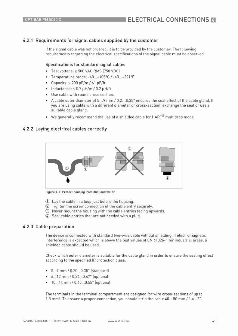
4.2.2 Laying electrical cables correctly
1 Lay the cable in a loop just before the housing.2 Tighten the screw connection of the cable entry securely.3 Never mount the housing with the cable entries facing upwards.4 Seal cable entries that are not needed with a plug.
4.2.3 Cable preparation
The device is connected with standard two-wire cable without shielding. If electromagnetic interference is expected which is above the test values of EN 61326-1 for industrial areas, a shielded cable should be used.
Check which outer diameter is suitable for the cable gland in order to ensure the sealing effect according to the specified IP protection class.
• 5...9 mm / 0.20...0.35" (standard)• 6...12 mm / 0.24...0.47" (optional)• 10...14 mm / 0.40...0.55" (optional)
The terminals in the terminal compartment are designed for wire cross-sections of up to 1.5 mm². To ensure a proper connection, you should strip the cable 40…50 mm / 1.6...2".
Figure 4-1: Protect housing from dust and water
TD_OPTIBAR_PM_5060_en_150423_TD_OPTIBAR_PM_5060_R01.book Page 41 Thursday, April 23, 2015 10:45 AM
4 ELECTRICAL CONNECTIONS
42
OPTIBAR PM 5060 C
www.krohne.com 04/2015 - 4003437001 - TD OPTIBAR PM 5060 C R01 en
4.2.4 Cable entry 1/2-14 NPT (female)
With plastic housings, the NPT cable gland or the conduit steel tube must be screwed without grease into the thread. For further information about max. torque for all housings refer to Technical data on page 10.
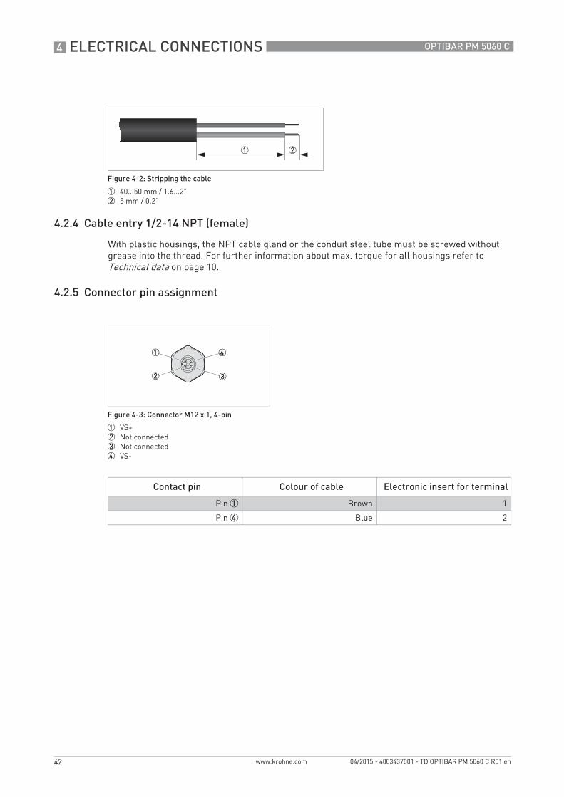
4.2.5 Connector pin assignment
Figure 4-2: Stripping the cable
1 40...50 mm / 1.6...2"2 5 mm / 0.2"
Figure 4-3: Connector M12 x 1, 4-pin
1 VS+2 Not connected3 Not connected4 VS-
Contact pin Colour of cable Electronic insert for terminal
Pin 1 Brown 1
Pin 4 Blue 2
TD_OPTIBAR_PM_5060_en_150423_TD_OPTIBAR_PM_5060_R01.book Page 42 Thursday, April 23, 2015 10:45 AM
ELECTRICAL CONNECTIONS 4
43
OPTIBAR PM 5060 C
www.krohne.com04/2015 - 4003437001 - TD OPTIBAR PM 5060 C R01 en
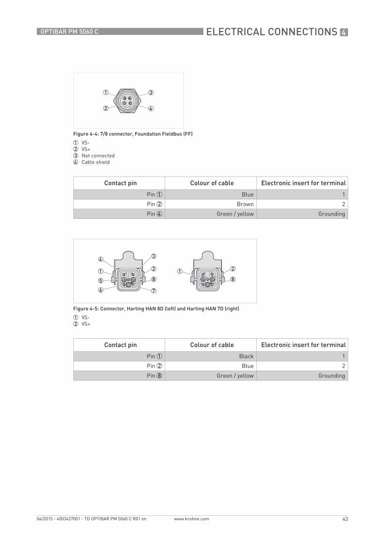
Figure 4-4: 7/8 connector, Foundation Fieldbus (FF)
1 VS-2 VS+3 Not connected4 Cable shield
Contact pin Colour of cable Electronic insert for terminal
Pin 1 Blue 1
Pin 2 Brown 2
Pin 4 Green / yellow Grounding
Figure 4-5: Connector, Harting HAN 8D (left) and Harting HAN 7D (right)
1 VS-2 VS+
Contact pin Colour of cable Electronic insert for terminal
Pin 1 Black 1
Pin 2 Blue 2
Pin 8 Green / yellow Grounding
TD_OPTIBAR_PM_5060_en_150423_TD_OPTIBAR_PM_5060_R01.book Page 43 Thursday, April 23, 2015 10:45 AM
4 ELECTRICAL CONNECTIONS
44
OPTIBAR PM 5060 C
www.krohne.com 04/2015 - 4003437001 - TD OPTIBAR PM 5060 C R01 en
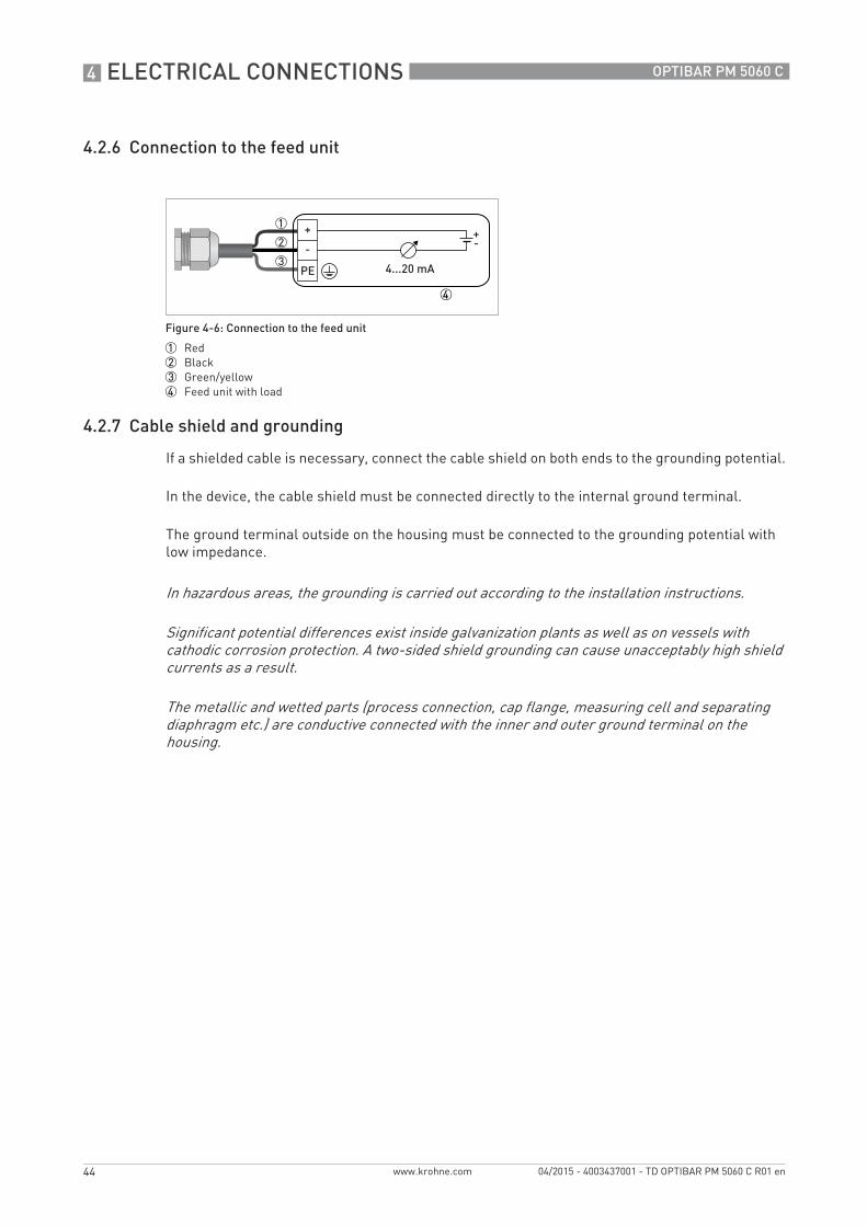
4.2.6 Connection to the feed unit
4.2.7 Cable shield and grounding
If a shielded cable is necessary, connect the cable shield on both ends to the grounding potential.
In the device, the cable shield must be connected directly to the internal ground terminal.
The ground terminal outside on the housing must be connected to the grounding potential with low impedance.
Figure 4-6: Connection to the feed unit
1 Red2 Black3 Green/yellow4 Feed unit with load
In hazardous areas, the grounding is carried out according to the installation instructions.
Significant potential differences exist inside galvanization plants as well as on vessels with cathodic corrosion protection. A two-sided shield grounding can cause unacceptably high shield currents as a result.
The metallic and wetted parts (process connection, cap flange, measuring cell and separating diaphragm etc.) are conductive connected with the inner and outer ground terminal on the housing.
TD_OPTIBAR_PM_5060_en_150423_TD_OPTIBAR_PM_5060_R01.book Page 44 Thursday, April 23, 2015 10:45 AM

ELECTRICAL CONNECTIONS 4
45
OPTIBAR PM 5060 C
www.krohne.com04/2015 - 4003437001 - TD OPTIBAR PM 5060 C R01 en
4.3 Electrical connection
The connection of the power supply and the signal output is carried out via spring-loaded terminals in the housing. The display and adjustment module is connected via contact pins with the interface adapter.
4.3.1 Connection in the terminal compartment
Procedure• Unscrew the housing cover.• If present, remove the display and adjustment module by turning it to the left.• Loosen union nut of the cable gland.• For preparation of connection cable refer to Cable preparation on page 41.• Push the cable through the cable gland into the terminal compartment.• Insert the wire ends into the open terminals according to the wiring plan. Flexible cores with
cable end sleeves as well as solid cores can be inserted directly into the terminal openings. In case of flexible cores, press the spring terminal with a small screwdriver to open the terminal opening.
• Check the proper hold of the wires in the terminals by lightly pulling on them.• Connect the cable shield to the internal ground terminal, connect the outer ground terminal to
the customer/plant equipotential bonding.• Tighten the union nut of the cable gland. The sealing ring must completely enclose the cable.• Screw the housing cover back on.
TD_OPTIBAR_PM_5060_en_150423_TD_OPTIBAR_PM_5060_R01.book Page 45 Thursday, April 23, 2015 10:45 AM
4 ELECTRICAL CONNECTIONS
46
OPTIBAR PM 5060 C
www.krohne.com 04/2015 - 4003437001 - TD OPTIBAR PM 5060 C R01 en
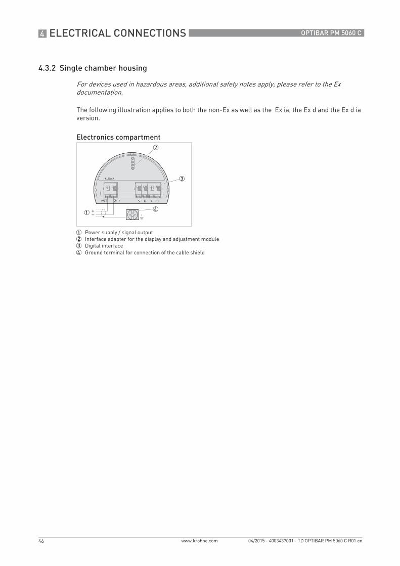
4.3.2 Single chamber housing
The following illustration applies to both the non-Ex as well as the Ex ia, the Ex d and the Ex d ia version.
For devices used in hazardous areas, additional safety notes apply; please refer to the Ex documentation.
Electronics compartment
1 Power supply / signal output2 Interface adapter for the display and adjustment module3 Digital interface4 Ground terminal for connection of the cable shield
TD_OPTIBAR_PM_5060_en_150423_TD_OPTIBAR_PM_5060_R01.book Page 46 Thursday, April 23, 2015 10:45 AM

ELECTRICAL CONNECTIONS 4
47
OPTIBAR PM 5060 C
www.krohne.com04/2015 - 4003437001 - TD OPTIBAR PM 5060 C R01 en
4.3.3 Double chamber housing
The following illustration applies to both the non-Ex as well as the the Ex ia, and the Ex d version.
For devices used in hazardous areas, additional safety notes apply; please refer to the Ex documentation.
Electronics compartment
1 Internal connection to terminal compartment2 Interface adapter for the display and adjustment module
Terminal compartment
1 Power supply / signal output2 Interface adapter for the display and adjustment module3 Ground terminal for connection of the cable shield
TD_OPTIBAR_PM_5060_en_150423_TD_OPTIBAR_PM_5060_R01.book Page 47 Thursday, April 23, 2015 10:45 AM

4 ELECTRICAL CONNECTIONS
48
OPTIBAR PM 5060 C
www.krohne.com 04/2015 - 4003437001 - TD OPTIBAR PM 5060 C R01 en
4.3.4 Double chamber housing Ex d ia
For devices used in hazardous areas, additional safety notes apply; please refer to the Ex documentation.
Electronics compartment
1 Power supply / signal output2 Interface adapter for the display and adjustment module3 Digital interface
Terminal compartment
1 Power supply / signal output2 Ground terminal for connection of the cable shield
TD_OPTIBAR_PM_5060_en_150423_TD_OPTIBAR_PM_5060_R01.book Page 48 Thursday, April 23, 2015 10:45 AM

ORDER INFORMATION 5
49
OPTIBAR PM 5060 C
www.krohne.com04/2015 - 4003437001 - TD OPTIBAR PM 5060 C R01 en
Order information
5.1 Order code
OPTIBAR PM 5060 COPTIBAR PM 5060 COPTIBAR PM 5060 COPTIBAR PM 5060 C
The characters of the order code highlighted in light grey describe the standard.
VGK5VGK5VGK5VGK5 4444 ApprovalApprovalApprovalApproval
AX Non-Ex zone Europe WX Non-Ex zone Europe
AC ATEX II 1G, 1/2G, 2G Ex ia IIC T6 WC IEC Ex ia IIC T6 Ga, Ga/Gb, Gb
AD ATEX II 1/2G, 2G Ex d ia IIC T6 WD IEC Ex d ia IIC T6, Ga/Gb, Gb
AE ATEX II 1/2G, 2G Ex d IIC T6 WE IEC Ex d IIC T6, Ga/Gb, Gb
AR ATEX II 1D, 1/2D,1/3D,2D IP66 WR IEC Ex t IIIC T... IP66
AH ATEX II 1G, 1/2G 2G Ex ia IIC + II 1D, 1/2D, 1/3D, 2D IP66
WH IEC Ex ia IIC T6 + IEC Ex t IIIC T... IP66
AT ATEX II 1G, 1/2G, 2G Ex ia IIC + 1/2/-D Ex t IIIC IP67/66
W1 IEC Ex d ia IIC T6 + IEC Ex t IIIC T... IP66
A1 ATEX II 1/2G, 2G Ex d ia IIC + II 1D, 1/2D, 1/3D, 2D IP66
WL IEC Ex d IIC T6 + IEC Ex t IIIC T... IP66
AL ATEX II 1/2G, 2G Ex d IIC + II 1D, 1/2D, 1/3D, 2D IP66
AS ATEX II 1/2/-D Ex t IIIC IP67/66 T.. Da/Db/-
Process connection / MaterialProcess connection / MaterialProcess connection / MaterialProcess connection / Material
DU Thread ISO228 G1/2 EN837-1, 316 L
LS Thread ISO228 G1/2, PN 1000, DIN 3852-E, 316 L
LF Thread ANSI 1/2-14 NPT (female) - 1/4-18 NPT (female), 316 L
DL Thread ANSI 1/2-14 NPT (female), 316 L
LY Thread ANSI 1/2-14 NPT (female), PN1000, 316 Ti
C2 Thread DIN 13 M20x1.5, EN 837-1, 316 L
LU Thread ISO228 G1/2 DIN 3852, with radial O-ring, flush, 316 L
P6 Thread ISO228 G1/2 DIN 3852, flush, Alloy C-276
C5 Thread ISO 228 G1, DIN 3852, 316 L
AT Clamp DN40 (1 1/2") PN16, DIN 32676 / ISO 2852
AR Clamp DN50 (2") PN16, DIN 32676 / ISO 2852, 316 L
ES Hygienic connection with clamp F40, PN25, 316 L
AA Flange DRD PN40, 316 L
FR Varivent® N, N40 - 50 PN25, 316 L
E5 Compression fitting DIN 11851, DN25, PN40, 316 L
EZ Compression fitting DIN 11851, DN40, PN40, 316 L
NB Compression fitting DIN 11851, DN50, PN25, 316 L
FA SMS, DN38, PN6, 316 L
FB SMS, DN51, PN6, 316 L
E2 Compression fitting DIN 11864-1 Form A, DN40, PN40, 316 L
E3 Compression fitting DIN 11864-1 Form A, DN50, PN40, 316 L
FD NEUMO Biocontrol, DN50 PN16, 316 L
FE NEUMO Biocontrol, DN65 PN16, 316 L
FH NEUMO BioConnect, DN80 PN25, 316 L
EV DB40L - DB50L, PN40, 316 L
TD_OPTIBAR_PM_5060_en_150423_TD_OPTIBAR_PM_5060_R01.book Page 49 Thursday, April 23, 2015 10:45 AM

5 ORDER INFORMATION
50
OPTIBAR PM 5060 C
www.krohne.com 04/2015 - 4003437001 - TD OPTIBAR PM 5060 C R01 en
N8 Flange DN25, PN40, Form B1, EN 1092-1, 316L
B3 Flange DN32, PN40, Form C, DIN 2501, 316 L
A8 Flange DN40, PN40, Form C, DIN 2501, 316 L
B2 Flange DN50, PN40, Form C, DIN 2501, 316 L
BP Flange DN65, PN40, Form C, DIN 2501, 316 L
B5 Flange DN80, PN40, Form C, DIN 2501, 316 L
CD Flange DN100, PN40, Form C, DIN 2501, 316 L
A6 Flange DN150, PN40, Form C, DIN 2501, 316 L
BW Flange 1" 150lb RF, ASME B16.5, 316 L
CA Flange 2" 150lb RF, ASME B16.5, 316 L
BG Flange 2" 300lb RF, ASME B16.5, 316 L
CB Flange 3" 150lb RF, ASME B16.5, 316 L
B4 Flange 3" 600lb RF, ASME B16.5, 316 L
BB Flange 4" 150lb RF, ASME B16.5, 316 L
B9 Flange DN15 16K FF, JIS B2200, 316 L
B7 Flange DN25 20K FF, JIS B2200, 316 L
cF Flange DN50 10K FF, JIS B2200, 316 L
BV Flange DN50 16K FF, JIS B2200, 316 L
CG Flange DN80 10K FF, JIS B2200, 316 L
CP Flange DN100 16K FF, JIS B2200, 316 L
Diaphragm / Fill fluidDiaphragm / Fill fluidDiaphragm / Fill fluidDiaphragm / Fill fluid
S 316 L, (1.4404), Silicone oil
E Elgiloy (2.4711), without
Gasket / TemperatureGasket / TemperatureGasket / TemperatureGasket / Temperature
S without, -40...+105°C / -40...+221°F
E without, -40...+150°C / -40...+302°F
1 FKM: -20...+105°C / -4...+221°F
3 EPDM: -30...+105°C / -22...+221°F
P FFKM: -15...+105°C / +5...+221°F
A FKM: -20...+150°C / -4...+302°F
C EPDM: -30...+150°C / -22...+302°F
K FFKM: -15...+150°C / +5...+302°F
Pressure typePressure typePressure typePressure type
A Absolute pressure
G Gauge pressure
Measuring rangeMeasuring rangeMeasuring rangeMeasuring range
C 0...400 mbar / 0...5.8 psi
D 0...1 bar / 0...14.5 psi
E 0...2.5 bar / 0...36 psi
G 0...10 bar / 0...145 psi
H 0...25 bar / 0...363 psi
K 0...40 bar / 0...580 psi
L 0...100 bar / 0...1450 psi
N 0...250 bar / 0...3630 psi
TD_OPTIBAR_PM_5060_en_150423_TD_OPTIBAR_PM_5060_R01.book Page 50 Thursday, April 23, 2015 10:45 AM

ORDER INFORMATION 5
51
OPTIBAR PM 5060 C
www.krohne.com04/2015 - 4003437001 - TD OPTIBAR PM 5060 C R01 en
M 0...600 bar / 0...8700 psi
P 0...1000 bar / 0...14500 psi
T -1...0 bar / -14.5...0 psi
U -1...1.5 bar / -14.5...21.8 psi
W -1...10 bar / -14.5...145 psi
X -1...25 bar / -14.5...363 psi
1 -1...40 bar / -14.5...580 psi
2 -1...100 bar / -14...1450 psi
Y Customer specific measuring range
AdjustmentAdjustmentAdjustmentAdjustment
0 Nominal range %
1 Nominal range mbar
2 Nominal range bar
3 Nominal range psi
4 Nominal range Pa
5 Nominal range kPa
6 Nominal range Mpa
7 Nominal range mmH20
8 Nominal range inH20
A Nominal range mmHG
B Nominal range inHG
C Nominal range mm (density 1)
D Nominal range cm (density 1)
E Nominal range m (density 1)
F Nominal range in (density 1)
G Nominal range ft (density 1)
Y Customer specific adjustment for pressure
Accuracy classAccuracy classAccuracy classAccuracy class
H 0.075%
E 0.1%
S 0.2%
ElectronicsElectronicsElectronicsElectronics
H 2-wire 4...20 mA / HART®
A 2-wire 4...20 mA / HART® with SIL (in preparation)
F Foundation Fieldbus
P Profibus PA
Supplementary electronicsSupplementary electronicsSupplementary electronicsSupplementary electronics
X Without
HousingHousingHousingHousing
K Plastic (PBT), DIN single chamber
R Plastic (PBT), DIN double chamber
A Aluminium, DIN single chamber
D Aluminium, DIN double chamber
8 316 L (electro-polished), DIN single chamber
TD_OPTIBAR_PM_5060_en_150423_TD_OPTIBAR_PM_5060_R01.book Page 51 Thursday, April 23, 2015 10:45 AM
5 ORDER INFORMATION
52
OPTIBAR PM 5060 C
www.krohne.com 04/2015 - 4003437001 - TD OPTIBAR PM 5060 C R01 en
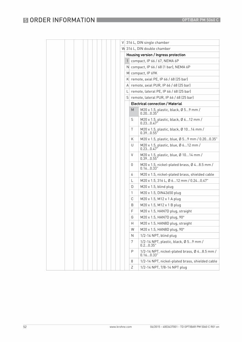
V 316 L, DIN single chamber
W 316 L, DIN double chamber
Housing version / Ingress protectionHousing version / Ingress protectionHousing version / Ingress protectionHousing version / Ingress protection
1 compact, IP 66 / 67, NEMA 6P
N compact, IP 66 / 68 (1 bar), NEMA 6P
M compact, IP 69K
K remote, axial PE, IP 66 / 68 (25 bar)
A remote, axial PUR, IP 66 / 68 (25 bar)
L remote, lateral PE, IP 66 / 68 (25 bar)
S remote, lateral PUR, IP 66 / 68 (25 bar)
Electrical connection / MaterialElectrical connection / MaterialElectrical connection / MaterialElectrical connection / Material
M M20 x 1.5, plastic, black, Ø 5...9 mm / 0.20...0.35"
S M20 x 1.5, plastic, black, Ø 6...12 mm / 0.23...0.47"
T M20 x 1.5, plastic, black, Ø 10...14 mm / 0.39...0.55"
K M20 x 1.5, plastic, blue, Ø 5...9 mm / 0.20...0.35"
U M20 x 1.5, plastic, blue, Ø 6...12 mm / 0.23...0.47"
V M20 x 1.5, plastic, blue, Ø 10...14 mm / 0.39...0.55"
0 M20 x 1.5, nickel-plated brass, Ø 4...8.5 mm / 0.16...0.33"
6 M20 x 1.5, nickel-plated brass, shielded cable
L M20 x 1.5, 316 L, Ø 6...12 mm / 0.24...0.47"
D M20 x 1.5, blind plug
1 M20 x 1.5, DIN43650 plug
C M20 x 1.5, M12 x 1 A plug
B M20 x 1.5, M12 x 1 B plug
F M20 x 1.5, HAN7D plug, straight
G M20 x 1.5, HAN7D plug, 90°
H M20 x 1.5, HAN8D plug, straight
W M20 x 1.5, HAN8D plug, 90°
N 1/2-14 NPT, blind plug
7 1/2-14 NPT, plastic, black, Ø 5...9 mm / 0.2...0.35"
P 1/2-14 NPT, nickel-plated brass, Ø 4...8.5 mm / 0.16...0.33"
8 1/2-14 NPT, nickel-plated brass, shielded cable
Z 1/2-14 NPT, 7/8-14 NPT plug
TD_OPTIBAR_PM_5060_en_150423_TD_OPTIBAR_PM_5060_R01.book Page 52 Thursday, April 23, 2015 10:45 AM
ORDER INFORMATION 5
53
OPTIBAR PM 5060 C
www.krohne.com04/2015 - 4003437001 - TD OPTIBAR PM 5060 C R01 en
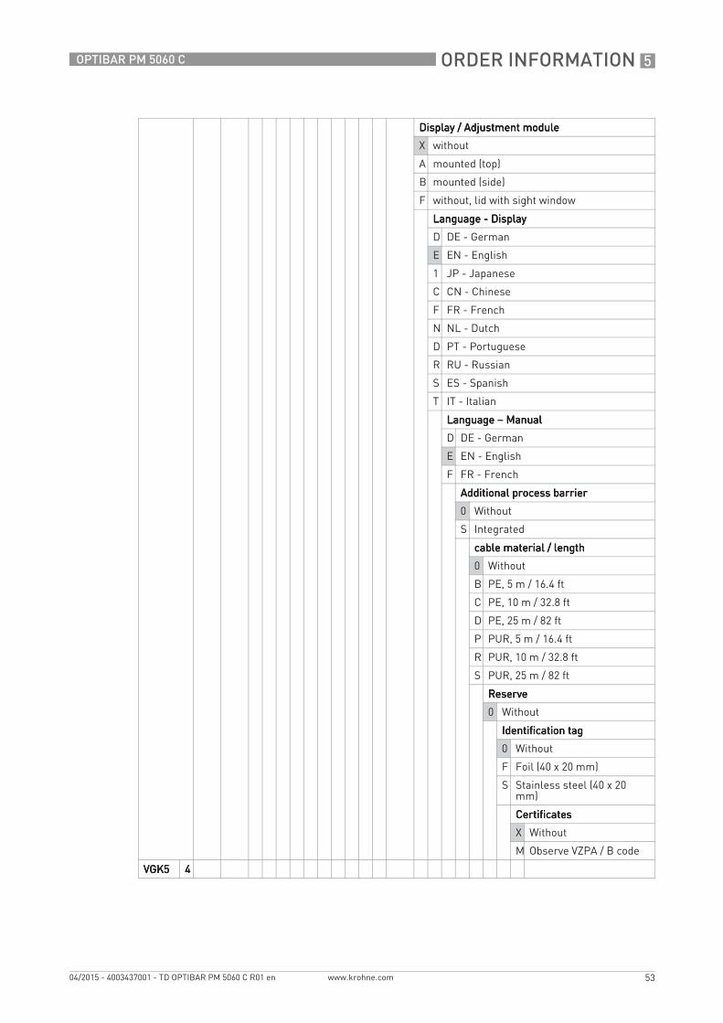
Display / Adjustment moduleDisplay / Adjustment moduleDisplay / Adjustment moduleDisplay / Adjustment module
X without
A mounted (top)
B mounted (side)
F without, lid with sight window
Language - DisplayLanguage - DisplayLanguage - DisplayLanguage - Display
D DE - German
E EN - English
1 JP - Japanese
C CN - Chinese
F FR - French
N NL - Dutch
D PT - Portuguese
R RU - Russian
S ES - Spanish
T IT - Italian
Language Language Language Language – Manual Manual Manual Manual
D DE - German
E EN - English
F FR - French
Additional process barrierAdditional process barrierAdditional process barrierAdditional process barrier
0 Without
S Integrated
cable material / lengthcable material / lengthcable material / lengthcable material / length
0 Without
B PE, 5 m / 16.4 ft
C PE, 10 m / 32.8 ft
D PE, 25 m / 82 ft
P PUR, 5 m / 16.4 ft
R PUR, 10 m / 32.8 ft
S PUR, 25 m / 82 ft
ReserveReserveReserveReserve
0 Without
Identification tagIdentification tagIdentification tagIdentification tag
0 Without
F Foil (40 x 20 mm)
S Stainless steel (40 x 20 mm)
CertificatesCertificatesCertificatesCertificates
X Without
M Observe VZPA / B code
VGK5VGK5VGK5VGK5 4444
TD_OPTIBAR_PM_5060_en_150423_TD_OPTIBAR_PM_5060_R01.book Page 53 Thursday, April 23, 2015 10:45 AM

6 NOTES
54
OPTIBAR PM 5060 C
www.krohne.com 04/2015 - 4003437001 - TD OPTIBAR PM 5060 C R01 en
Notes
TD_OPTIBAR_PM_5060_en_150423_TD_OPTIBAR_PM_5060_R01.book Page 54 Thursday, April 23, 2015 10:45 AM

NOTES 6
55
OPTIBAR PM 5060 C
www.krohne.com04/2015 - 4003437001 - TD OPTIBAR PM 5060 C R01 en
TD_OPTIBAR_PM_5060_en_150423_TD_OPTIBAR_PM_5060_R01.book Page 55 Thursday, April 23, 2015 10:45 AM
KROHNE product overview
• Electromagnetic flowmeters
• Variable area flowmeters
• Ultrasonic flowmeters
• Mass flowmeters
• Vortex flowmeters
• Flow controllers
• Level meters
• Temperature assemblies
• Pressure transmitters
• Analysis products
• Products and systems for the oil & gas industry
• Measuring systems for the marine industry
Head Office KROHNE Messtechnik GmbHLudwig-Krohne-Str. 547058 Duisburg (Germany)Tel.:+49 203 301 0Fax:+49 203 301 103 89 [email protected]
© K
RO
HN
E 04
/201
5 -
4003
4370
01 -
TD
OP
TIB
AR
PM
506
0 C
R01
en
- Su
bjec
t to
chan
ge w
ithou
t not
ice.
The current list of all KROHNE contacts and addresses can be found at:www.krohne.com
KK
K
TD_OPTIBAR_PM_5060_en_150423_TD_OPTIBAR_PM_5060_R01.book Page 56 Thursday, April 23, 2015 10:45 AM