opportunities and challenges for power electronics in pv ... · power electronics: example: dc -dc...
TRANSCRIPT

NREL is a national laboratory of the U.S. Department of Energy, Office of Energy Efficiency and Renewable Energy, operated by the Alliance for Sustainable Energy, LLC.
Opportunities and Challenges for Power Electronics in PV Modules
National Centerfor
Photovoltaics
ARPA E WorkshopFebruary 8, 2011
Arlington, VASarah KurtzChris Deline
John WohlgemuthBill Marion
Jennifer Granata
NREL/PR-5200-50826

Outline What are we talking about?
– Power electronics: DC-DC converters, smart bypass diodes, microinverters– Imperfect solar cells– Ways to implement power electronics in module
Opportunities: Enables new technologies/approaches– Non-uniform thin film and thin silicon wafers that sometimes crack– High-shading configurations– Potential to mitigate safety issues– System-level savings
Challenges: Daunting for some implementations; easier for others– Efficiency – parasitic losses can be greater than benefits– Cost – goal is to reduce cost of power electronics by factor of two, while
increasing performance– Reliability – could be a nightmare
Conclusions
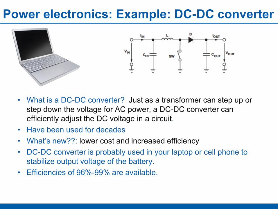
Power electronics: Example: DC-DC converter
• What is a DC-DC converter? Just as a transformer can step up or step down the voltage for AC power, a DC-DC converter can efficiently adjust the DC voltage in a circuit.
• Have been used for decades• What’s new??: lower cost and increased efficiency• DC-DC converter is probably used in your laptop or cell phone to
stabilize output voltage of the battery. • Efficiencies of 96%-99% are available.

Imperfect Solar Cells
• A solar cell may produce less electricity because of reduced photocurrent.
• Today’s thinner Si cells sometimes crack.
• Could power electronics help?
• Solar cells may fail in lots of ways. • Usually the fill factor (squareness
of the curve) is reduced• Increased series resistance may be
most common, but not always• Usually, all parameters are affected• Could power electronics help?
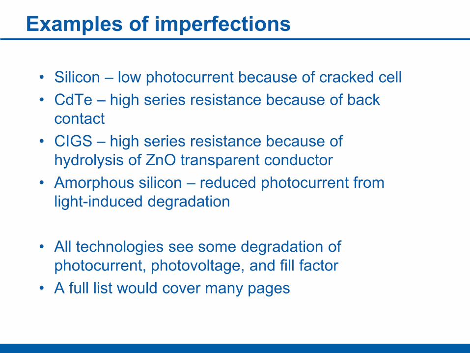
Examples of imperfections
• Silicon – low photocurrent because of cracked cell• CdTe – high series resistance because of back
contact • CIGS – high series resistance because of
hydrolysis of ZnO transparent conductor• Amorphous silicon – reduced photocurrent from
light-induced degradation
• All technologies see some degradation of photocurrent, photovoltage, and fill factor
• A full list would cover many pages

Wiring in modules – examples incorporating power electronics-+ Bypass diodes
Conventional wiring
-+ Power electronics
String-level electronics
+ -
Cell-level electronics
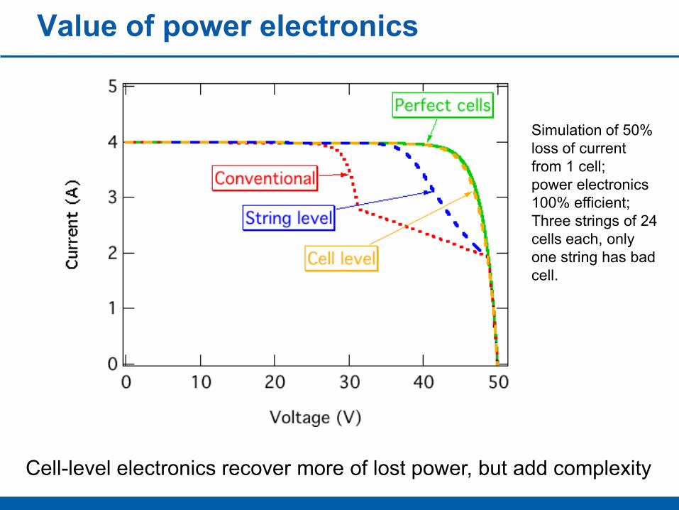
Value of power electronics
Simulation of 50% loss of current from 1 cell; power electronics 100% efficient; Three strings of 24 cells each, only one string has bad cell.
Cell-level electronics recover more of lost power, but add complexity
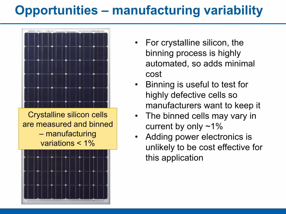
Opportunities – manufacturing variability
Crystalline silicon cells are measured and binned
– manufacturing variations < 1%
• For crystalline silicon, the binning process is highly automated, so adds minimal cost
• Binning is useful to test for highly defective cells so manufacturers want to keep it
• The binned cells may vary in current by only ~1%
• Adding power electronics is unlikely to be cost effective for this application
Opportunities – manufacturing variability
Most thin-film cells cannot be binned; variability can be large, especially for new products, providing possible opportunity for
power electronics
• Strips in thin-film modules cannot be binned
• Variability across thin-film module can be high
• Opportunity for power electronics, but challenging to implement
• Adding power electronics to each cell will require redesign of module
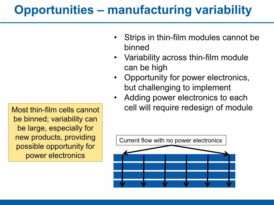
Current flow with no power electronics
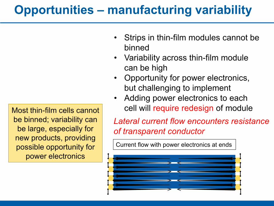
Opportunities – manufacturing variability
Most thin-film cells cannot be binned; variability can be large, especially for new products, providing possible opportunity for
power electronics
• Strips in thin-film modules cannot be binned
• Variability across thin-film module can be high
• Opportunity for power electronics, but challenging to implement
• Adding power electronics to each cell will require redesign of module
Current flow with power electronics at ends
Lateral current flow encounters resistance of transparent conductor

Opportunities – degradation variability
Immature thin-film PV designs show variable degradation – opportunity for power electronics?
Thin-film modules deployed in Florida

Opportunities – enables new technologies
Thinner silicon cells have lower cost but are observed to crack sometimes
+ DC-DC converters can mitigate issues if thin cells break
- May be a temporary problem: broken cells are undesirable –need to avoid breakage
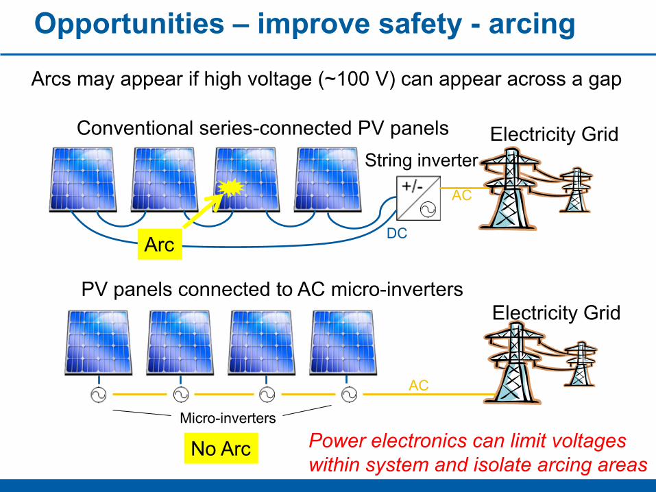
Opportunities – improve safety - arcing
Arcs may appear if high voltage (~100 V) can appear across a gap
String inverterElectricity GridConventional series-connected PV panels
DC
AC
PV panels connected to AC micro-invertersElectricity Grid
AC
Micro-inverters
Arc
No Arc Power electronics can limit voltages within system and isolate arcing areas

Opportunities – improve safety – hot spotsHot spots can be caused by shading1. Shading blocks flow of current2. Shaded cell goes into reverse bias3. Bypass diode protects cell4. If bypass diode fails, heating may be severe5. Smart electronics may be more effective
Shaded cell is forced into reverse bias
-+ Bypass diodes
Shaded cell is forced into reverse bias; power dissipation can be severe; can cause thermal runaway or accelerated degradation
“Hot-spot test” is part of qual test
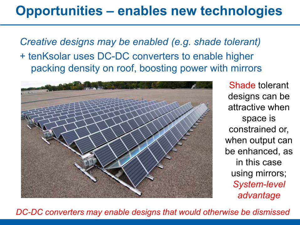
Opportunities – enables new technologies
Creative designs may be enabled (e.g. shade tolerant)+ tenKsolar uses DC-DC converters to enable higher
packing density on roof, boosting power with mirrors
DC-DC converters may enable designs that would otherwise be dismissed
Shade tolerant designs can be attractive when
space is constrained or,
when output can be enhanced, as
in this case using mirrors; System-level advantage
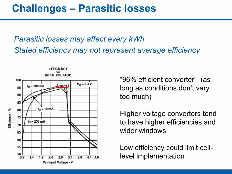
Challenges – Parasitic losses
Parasitic losses may affect every kWhStated efficiency may not represent average efficiency
“96% efficient converter” (as long as conditions don’t vary too much)
Higher voltage converters tend to have higher efficiencies and wider windows
Low efficiency could limit cell-level implementation
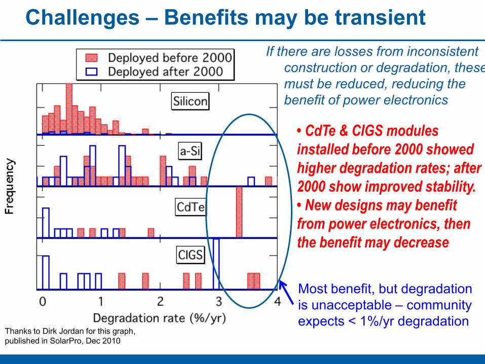
Challenges – Benefits may be transientIf there are losses from inconsistent
construction or degradation, these must be reduced, reducing the benefit of power electronics
• CdTe & CIGS modules installed before 2000 showed higher degradation rates; after 2000 show improved stability. • New designs may benefit from power electronics, then the benefit may decrease
Thanks to Dirk Jordan for this graph, published in SolarPro, Dec 2010
Most benefit, but degradation is unacceptable – community expects < 1%/yr degradation
Challenges – Cost
At cell level, any increase in cost needs to be offset by increased performance
If used to replace bypass diodes, then cost target is equal or less than diode cost (~0.1 cent/W)
If power electronics can replace the inverter, then cost goal is half of current cost.
Two strategies:- Look for ways to avoid cost (materials or processing)- Look for ways to increase power so that higher cost can
be tolerated
Challenges – Reliability
At cell level, power electronics that fail will be a nightmareToday’s inverters are weakest part of the system, but are tolerated because replacement can be simple. Elecctronics embedded in the module must match the reliability of the module
At string level, power electronics could be in junction box, making them replaceable, but replacement for a field would still be a nightmare
At module level, reliability is still important, but replacement becomes more feasible, especially if devices are self diagnostic
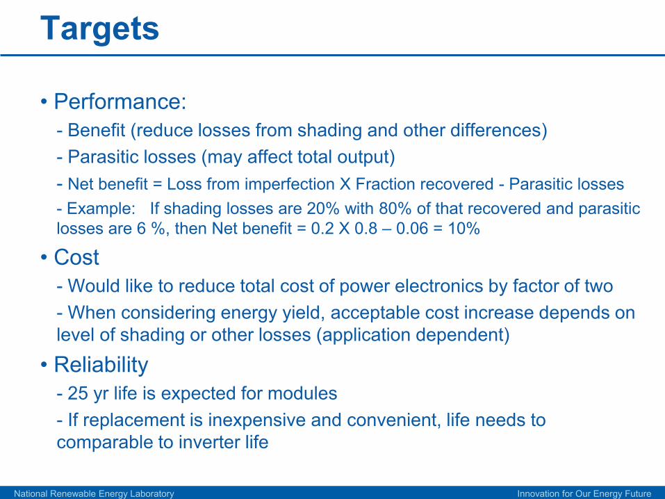
Targets
• Performance:- Benefit (reduce losses from shading and other differences) - Parasitic losses (may affect total output)- Net benefit = Loss from imperfection X Fraction recovered - Parasitic losses- Example: If shading losses are 20% with 80% of that recovered and parasitic losses are 6 %, then Net benefit = 0.2 X 0.8 – 0.06 = 10%
• Cost- Would like to reduce total cost of power electronics by factor of two- When considering energy yield, acceptable cost increase depends on level of shading or other losses (application dependent)
• Reliability- 25 yr life is expected for modules- If replacement is inexpensive and convenient, life needs to comparable to inverter life
National Renewable Energy Laboratory Innovation for Our Energy Future
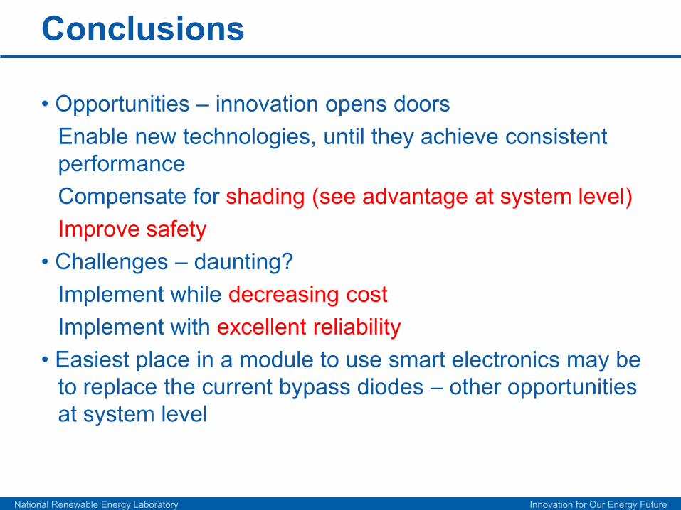
Conclusions
• Opportunities – innovation opens doorsEnable new technologies, until they achieve consistent performance Compensate for shading (see advantage at system level)Improve safety
• Challenges – daunting?Implement while decreasing costImplement with excellent reliability
• Easiest place in a module to use smart electronics may be to replace the current bypass diodes – other opportunities at system level
National Renewable Energy Laboratory Innovation for Our Energy Future
Resources
National Renewable Energy Laboratory Innovation for Our Energy Future
http://www.nrel.gov/docs/fy11osti/50003.pdf
[email protected]@[email protected]@sandia.gov