operator's manual unic hydraulic craneunic hydraulic crane operator's manual model...
TRANSCRIPT

UNIC HYDRAULIC CRANEOPERATOR'S MANUAL
MODEL
OMURV346-C 201008A
HEAD OFFICE : Nihonbashi nishikawa Bldg, 5-3, Nihonbashi 1-chome, Chuo-ku, Tokyo 103-0027, Japan
URV346-C


A FEW WORDS BEFORE YOU READ THIS MANUAL:THIS MANUAL'S PURPOSE IS TO EMPHASIZE TO YOU THE SAFETY
ASPECTS OF OPERATING THE UNIC CRANE. OURGOAL IS TO DESCRIBE EQUIPMENT,EXPLAIN THE OPERATING
CHARACTERISTICS, AND TO PROVIDE EXAMPLES OF PROCEDURESYOU WILL ENCOUNTER IN DAY TO DAY OPERATlONS.
SAFETY IS OF PRIME CONCERN TO FURUKAWA UNIC CORPORATlON.THISMANUAL WAS WRITTEN TO PROMOTE YOUR SAFETY AND THE
SAFETY OF OTHERS.
NOTICE
COPYRIGHT 1990, FURUKAWA UNIC CORPORATION.ALL ILLUSTRATIONS AND SPECIFICATIONS CONTAINED IN THISMANUAL ARE BASED ON THE LATEST PRODUCT INFORMATION
AVAILABLE AT THE TlME OF PUBLICATlON. RIGHT IS RESERVED TOMAKE CHANGES AT ANY TIME, WITHOUT NOTICE,lNSPECIFICATIONS, MATERIALS AND DESCRIPTIONS.
FURUKAWA UNIC CORPORATION, Nihonbashi nishikawa Bldg.,5-3,Nihonbashi 1-chome,Chuo-ku, Tokyo 103-0027,Japan
MADE IN JAPAN
[Caution]CHANGES OR MODIFICATlONS TO THE CRANE NOT EXPRESSLYAPPROVED BY THE MANUFACTURER COULD VOID THE WARRANTY.


TABLE OF CONTENTS
■ SAFETYSAFETY RULES …………………………………………………………………………… 1- 1
■ OPERATOR'S STATION1.INTRODUCTION ………………………………………………………………………… 2- 12. DESCRIPTION OF MAJOR EQUIPMENTS ………………………………………… 2- 2
2-1. Names of Crane Parts …………………………………………………………… 2- 23. SPECIFICATIONS ……………………………………………………………………… 2- 34. OPERATIONS …………………………………………………………………………… 2- 5
4-1. CONTROLS IDENTIFICATION …………………………………………………… 2- 54-2. OPERATING INSTRUCTIONS …………………………………………………… 2-104-3. MAXIMUM LOAD AND BOOM ANGLE CHART ……………………………… 2-144-4. GENERAL RULES ………………………………………………………………… 2-204-5. OPERATING THE UNIT …………………………………………………………… 2-214-6. LIFTING THE LOAD ……………………………………………………………… 2-284-7. ROADING THE UNIT ……………………………………………………………… 2-29
5.PLACARDS ……………………………………………………………………………… 2-30
■MAINTENANCE SECTION1. PERIODIC MAINTENANCE …………………………………………………………… 3- 12. PERIODIC MAINTENANCE/DAlLY ………………………………………………… 3- 2
2-1. WALK-AROUND INSPECTION …………………………………………………… 3- 22-2. INSPECTION FOR FUNCTION …………………………………………………… 3- 32-3. WIRE ROPE INSPECTION………………………………………………………… 3- 4
3.PERIODIC MAINTENANCE/WEEKLY ……………………………………………… 3- 64.PERIODIC MAINTENANCE/MONTHLY ……………………………………………… 3- 7
4-1. LUBRICATE SWING BEARING ………………………………………………… 3- 74-2. CHECK GEAR OIL LEVEL ……………………………………………………… 3- 74-3. LUBRICATE WIRE ROPE FOR BOOM EXTENSION ………………………… 3- 8
5.PERIODIC MAINTENANCE/ANNUAL ……………………………………………… 3- 95-1. CHANGE GEAR OIL ……………………………………………………………… 3- 95-2. CHECKING SWING BEARING MOUNTING BOLTS ………………………… 3-10
6. PERIODIC MAINTENANCE/REPLACEMENT OF EXPENDABLE PARTS ……… 3-11
■ OTHERS1.RECOMMENDED GREASE …………………………………………………………… 4- 12.RECOMMENDED GEAR OIL ………………………………………………………… 4- 13. RECOMMENDED HYDRAULIC OIL ………………………………………………… 4- 24.HYDRAULIC CIRCUIT ………………………………………………………………… 4- 35.EMERGENCY RELEASE ……………………………………………………………… 4- 4


■ SAFETY

1-1
SAFETY RULESYour safety depends on the condition of the crane and the use of proper operating proce-dures.The checks and maintenance procedures described in this manual will help to keep your crane in reliable condition. Use of the recommended operating procedures will help you avoid unsafe practices.Danger and warning notes have been included throughout this manual to help you avoid in-jury and to prevent damage to the equipment.These notes are not intended to cover all eventualities; lt would be impossible to anticipate and evaluate all possible applications and methods of operation for this equipment.lt is important that any procedure not specifi cally recommended be thoroughly evaluated from the standpoint of safety before it is placed in practice.
YOU MUST NOT OPERATE THIS CRANE UNLESS:1. You have been trained in the safe operation of this crane.2. You read,understand and follow the safety and operating recommendations contained
in the crane manufacturer's manuals, your employer's work rules and applicable gov-ernment regulations.
BEFORE THE OPERATION

1-2
ELECTROCUTION HAZARDTHIS CRANE IS NOT INSULATED
DEATH OR SERIOUS INJURY WILL RESULT FROM CONTACT OR INADEQUATE CLEARANCE.
● Maintain safe clearances from electrical lines. Allow for boom, electrical line, and load line swaying.
● This crane does not provide protection from contact with or proximity to an electrically charged conductor.
● Maintain a clearance of at least 10 feet between any part of the crane, loadline or load and any elctrical line carrying up to 50,000 volts. One foot additional clearance is required for every additional 30,000 volts or less.
DANGER

1-3
WARNING
FAILURE TO OBEY THE FOLLOWING CAN RESULT IN DEATH OR SERIOUS INJURY.● Do not operate any outrigger unless you or a signal person can see that all personnel are
clear of the outrigger and its ground contact point.● For crane stability use only solid, level surface with outriggers properly extended.● Crane must be level. (If it is necessary to operate the crane with the vehicle on elevated
track then consult the relevant load charts for guidance.)● Operate all controls slowly and smoothly.● Never operate the crane with personnel under boom or load.● Keep at least 3 wraps of load line on winch drum.● Do not overload.
Always know your operating radius, and the actual weight of load being lifted.● Never hoist personnel on hook, load or any device attached to loadline.● For travel, boom and outriggers must be in stowed position.

1-4
CAUTION
● Inspect vehicle and crane including operation, prior to use daily.● Failure to allow oil to warm up may cause damage to pump and slow response to func-
tion controls.● Play loadline out before extending or lowering boom.● When operating unit, keep boom clear or overhead obstructions.● Keep load under boom tip.
Do not side load boom or drag loads. Avoid free swinging loads.
● Disengage P.T.O. before driving truck.● Do not modify or alter this crane without written UNIC factory approval.
Use only UNIC approved or factory supplied attachments or spare parts on this crane.● Crane must be mounted on factory recommended chassis. If remounted or rebuilt, the
crane must be recertifi ed.


■ OPERATOR'S STATION

2-1
1.INTRODUCTIONThis manual is furnished with your UNIC crane. Its purpose is to acquaint you with the safety rules, operating characteristics and equipment checks. To properly utilize the fullpotential of your crane, we feel you must:
If the crane is supplied with optional equipment, read and understand additional instructions supplied by FURUKAWA UNIC CORPORATION or the authorized dealer.
Note: OSHA prohibits the alteration or modifi cation of this crane without written factory approval.
FURUKAWA UNIC CORPORATION cranes are manufactured in accordance with the ap-plicable portions of OSHA regulation, #1910.180 and 1926.550 as in effect at date of manu-facture.
1. Observe all safety rules.2. Understand the equipment.3. Do not operate this crane until you read and understand this manual.
The UNIC crane is hydraulically powered and consists of a base and independent outrig-gers. Each outrigger is independently controlled and has double acting cylinders to actuate its legs. A hydraulic motor, driven through a worm gear assembly, powers the rotating bull gear attached to the turntable. The units are equipped with dual control stations, hoist winch, and multistage extending boom assembly. The power source is provided by the truck engine driving the hydraulic pump with a transmission mounted P.T.O. (Power-Take-Off) .
■ GENERAL DESCRIPTION
You are the key safety factor in achieving good performance and long life of the unit.Even though you may be experienced in crane operations, you must read, understand and follow the instructions in this manual. Learn to operate the unit in a safe and effi cient man-ner.
■ OPERATOR RESPONSIBILITY

2-2
2. DESCRIPTION OF MAJOR EQUIPMENTS2-1. Names of Crane Parts
16
17
9
10
11
12
13
14
8
3 6 5
4
2
118
7
15
No. Descri ption
1 Boom
2 Column
3 Base
4 Hoist winch
5 Slewing gear
6 Topping cylinder
7 Telescoping cylinder
8 Outrigger
9 Boom topping control lever
No. Descri ption
10 Winch control lever
11 Boom telescoping control lever
12 Swing control lever
13 Outrigger control lever (Street side)
14 Outrigger control lever (Curb side)
15 Hook block
16 Warning horn
17 Wire rope
18 Boom angle indicator

2-3
3. SPECIFICATIONSCRANE CAPACITY:LIFTING CAPACITY : Max. 8000 Ibs. at 6.8 ft. with 4 part loadline.HOOK HEIGHT ABOVE GROUND : Max. 52.0 ft. (Approx.)WORKING RADIUS : Min. 2.4 ft. to Max. 47.3 ft.
BOOM: 6-section box beam type telescoping boom with boomangle indicator.
Boom Length All booms retracted; 11.9 ft. Second stage extended; 19.2 ft. Third stage extended; 26.4 ft. Fourth stage extended; 33.6 ft. Fifth stage extended; 40.7 ft. Sixth stage extended; 47.9 ft.Boom Telescoping Cylinder; Double acting type with counterbalance valve. Boom extending speed; 36.0 ft/20 sec.Boom Raising Cylinder; Double acting type with counterbalance valve. Boom raising speed; 1° to 78°/7 sec.
WINCH: Hydraulic motor driven, spur gear reduction, with automatic mechanical brake.
Single Line Pull ; 2000 lbs.Hoisting Speed Single line speed; 249 ft/min. at 4th layer. Hook speed; 62.3 ft/min. at 4th layer with 4 part loadline.Hook Block; 8000 Ibs. capacity, 2 sheaves with latch.Hydraulic Motor; Axial plunger type.Wire Rope Construction ; 6 × 26 Warrington-seale (ISO 2408) Diameter × Length; 5/16 in. × 279 ft. Breaking force; 37.4 KN
SWING: Hydraulic motor driven, worm and spur gears reduction,worm self-locking brake.
Swing Range; 360° continuous rotation on a ball bearing race.Hydraulic Motor; Trochoid type.Swing Speed; 2.5rpm.

2-4
OUTRIGGERS: Vertical jacks and horizontal beams.Vertical Jacks; Double acting hydraulic cylinders with pilot-operated check
valves.Horizontal Beams; Drive side: Fixed
Curb side: manually extendable and retractable type.
Outrigger Span Retracted; 6.99 ft. Extended; 10.34 ft.
Note: The fi gures in relation to the speed are on the basis of no-load running at rated oil fl ow condition.
HYDRAULIC SYSTEM:Control Valve; Multiple control valve, spring centered, spool-type, with
pressure relief valve.Pressure relief valve setting; 2,990 psi.Recommended Hydraulic Pump Rated pressure; 2,990 psi. Rated delivery; 15.9 gal/min.
ANTI TWO-BLOCK SYSTEMThis system senses the presence of the load block in closeproximity to the boom tip and automatically interrupts theoperation of those boom functions which could bring theload block in contact with the boom tip.Those boom functions which could be used to move theload block away from the boom tip remain operational.This system is fully automatic and does not have any typeof manual overriding.
ELECTRICAL SYSTEM 12 volt DC.

2-5
4-1. CONTROLS IDENTIFICATION
A. CAB CONTROLS
4. OPERATIONS
The P.T.O. / pump control is located within the driver's reach. The P.T.O. is engaged when the knob is moved up and disengaged when the knob is moved in.The truck gear shift must be in the neutral position when the P.T.D. is to be engaged.
Disengage P.T.O. before driving truck. Failure to do so will cause damage to the trans-mission and pump.
Note; The park brake must be fi rmly set before leaving the cab to begin operation. If the ground surface is icy, slick or sloped, you will be required to help stabilize the truck with wheel chocks.
CAUTION

2-6
B. CRANE MANUAL CONTROLSThe UNIC CRANE can be operated with the operator control station. The controls on the base side are; boom raise, hoist, telescope and boom swing and outrigger system. All con-trols and direction of actuation for desired movement are identifi ed by the information placard mounted on knob of the control lever.
To slewclockwise
To slewcounter-clockwise
Swing lever
Boom extention lever
To retract boom To extend boom
Hook hoisting lowering lever
To hoist hook To lower hook
Boom topping lever
To raise boom To lower boom
Boom: To raise boom, move lever to left; To lower boom, move lever to right.
Hoist: To hoist hook, move lever to left; To lower hook, move lever to right.
Extension: To retract boom, move lever to left; To extend boom, move lever to right.
Swing: To rotate boom clockwise, move lever to left; To rotate boom counter- clockwise, move lever to right.
Note: Controls must be used together to achieve combinations of movements. For instance, the boom extension and loadline (hoist) must be used together to maintain clearance between boom tip and hook block.

2-7
C. OUTRIGGER CONTROLS
WARNING1. Stand clear of outriggers to avoid crushing injury.2. Do not operate outriggers without determining clearance from obstructions or per-
sonnel.3. Never lower or raise any outrigger unless you or the signal person assisting you
can see the outrigger shoe and the ground where the outrigger will make contact and can confi rm the area is clear of all personnel.
4. Failure to follow this procedure may result in a serious crushing injury to workmen, property damage, or crane instability.
Extend Retract
Outrigger (curb side)
Extend
Outrigger (street side)
Retract
Outriggers: To extend outrigger cylinder, move lever to left; To retract outrigger cylinder, move lever to right.

2-8
★ Set up the outriggers in the following manner.
(3) Move the outrigger control lever to push to extend the outrigger cylinders.
(4) In order to brace the vehicle, for crane op-eration adjust the extension of each out-rigger cylinder by the control lever.
(5) After setting up the vehicle, return the control levers to the neutral positions.
(1) Pull out the pin to extend the outrigger lat-erally. The pin is secured with a chain and locating cotter pin.
(2) After the outrigger has been extended, re-turn the lock pin back into place and check to confi rm that the pin is inserted securely into the hole by pushing the outrigger in.
(Minimum extended state)
①
② Lock pin
Handle
③
(Maximum extended state)
Lock pin
Lock hole forretracting
CAUTIONWhen pulling out the stay lock pin, be sure to lift the handle up and support the out-rigger with your hand to extract the lock pin.

2-9
D. WARNING HORNThe warning horn switch is installed to horn on curb side only as well as remote of the crane body. The horn of the vehicle will sound to warn if the switch is pressed. Warn the co-worker near the load when starting crane operation or anyone who has entered the swinging range during crane operation.
Warning horn switch

2-10
4-2. OPERATING INSTRUCTIONS
A. TRAININGIt is extremely important that you have a thorough knowledge of all the operating character-istics of your crane.This crane will not be safe if improperly used!
B. SAFETY DEVICESCertain safety devices on your UNIC crane are described below. These devices will help to maintain control of a load should power or hydraulic line failure occur. You must understand the function and operation of these devices so that a continual check on their performance can be made.
WARNING
1. You have been trained in the safe operation of this crane.2. You read, understand and follow the safety and operating recommendations con-
tained in the crane manufacturer’s manuals, your employer’s work rules and ap-plicable government regulations.
YOU MUST NOT OPERATE THIS CRANE UNLESS:
CAUTIONShould any of these devices fail to function, stop all operations and consult your au-thorized UNIC dealer.This crane can be overloaded by an operator who fails to follow the instructions con-tained in this manual.

2-11
■ BOOM LIFT CYLINDER HOLDING VALVEA holding valve is subplate mounted to the cylinder base. This valve holds the boom in the elevated position should power or hydraulic pressure line failure occur. Should any of these happen, "STOP NOW". If the boom creeps down, consult your authorized UNIC dealer.
■ EXTENSION CYLINDER HOLDING VALVEA holding valve is subplate mounted to the cylinder rod end for more than 2nd stage ex-tension. This valve holds the cylinder in the extended position should power or hydraulic pressure line failure occur. If the boom creeps in under the load, consult your authorized UNIC dealer.
■ OUTRIGGER CYLINDER HOLDING VALVEAll outriggers are equipped with internal cartridge type lock valves. If outriggers creep up under load, or down while roading, consult your authorized UNIC dealer.
■ WINCH SAFETY BRAKETo determine if the brake is working, raise the load a few feet and release control lever. Shut truck engine off ; Actuate winch control lever in down direction. If the load creeps down, consult your authorized UNIC dealer.
■ SWING DRIVE BRAKE (ROTATION GEAR BOX)The rotation gear drive will have a worm self-locking brake.

2-12
■ ANTI TWO-BLOCKAn anti-two-block system senses the presence of the load block in close proximity to the boom tip and will automatically interrupt the operation of those boom functions which could bring the load block in contact with the boom tip. Those boom functions which could be used to move the load block further from the boom tip remain operational.
C. COLD WEATHER OPERATIONIn winter and cold weather, the crane must not be operated immediately after engaging the P.T.O.
CAUTIONFailure to allow oil to warm up may cause damage to pump and slow response to function controls.
D. WORK SITE POSITIONThe best possible work site should always be sought when you are positioning the crane. An ideal location is where the ground is fi rm, level and dry, and situated in close proximity to the work station. The site also should be as free of overhead obstructions as possible. Maintain safe clearances from electrical power lines and apparatus. You must allow for boom and platform sway, rock or sag and electrical line and loadline swaying.

2-13
E. OUTRIGGER POSITIONINGBefore conducting any boom operation you must extend all outriggers to a fi rm and level surface. In the event that other conditions exist such as: loose or sandy soil; crusty or frosty surface with soft soil underneath; icy or slick pavement; sloping surfaces, etc., you will be required to restrict operations. In some areas you may be able to level your crane with the use of outrigger pads or blocks. These pads must be made of adequate material.
F. LOAD HANDLING OPERATIONSBefore moving a load, you must study the capacity placards carefully and adhere to the load capacities and radii of operation given. The information provided on this load chart is based on 85% of tipping. During operations when lifting, swinging, or extending the load the controls should always be metered when beginning or terminating movement to prevent sudden start-ing or stopping which imposes undue shock loads on the equipment. This is especially true when handling heavy loads.The controls should be metered to begin slow continuous movement, then slowly increased to desired operating speed. Never hold a control lever in the open position after the function has reached the end of its travel. This will impose unnecessary stresses on the components, reduce service life, and generate heat in the hydraulic oil.

2-14
4-3. MAXIMUM LOAD AND BOOM ANGLE CHART
The maximum load charts shown are located on the operator console. Their purpose is to show you the load capacities at the various radii or boom angle and hook heights.
The boom angle indicator is located on the boom just above the operator’s station. Its pur-pose is to show the boom angle. This information may be used in conjunction with the load charts.

2-15
Boom(1) Boom(2)
Boom(3)
All booms are completely retracted.
Boom(2) is extended.
Boom is extended to the mark on the side plate of Boom(3).
Boom is extended to where 2nd mark on the side plate of Boom(3) is visible.
Boom is extended to where 3rd mark on the side plate of Boom(3) is visible.
Boom (2),(3),(4),(5) and (6) are all extended to their extremes.
Boom(4)
Boom(5)
Boom(6)
Boom(1) Boom(2)
Boom(3)
Boom(4)
Boom(5)
Boom(6)
Boom(1) Boom(2)
Boom(1) Boom(2)
Boom(3)
Boom(4) Boom(5)
Boom(6)
Boom(3)
Boom(4)
Boom(4)
Boom(5)
Boom(1) Boom(2) Boom(3) Boom(5)
Boom(1) Boom(2) Boom(3) Boom(5)
Boom(6)
Boom(6)
Boom(4) Boom(6)
OPERATING CONDITIONS OF BOOMSThe booms start to extend with the outer boom and to retract with the top boom.
(1) 6- section boom. The booms (2) and (3) extend in the order stated, and then the booms (4) , (5) and (6) extend simultaneously. The booms (6) , (5) and (4) retract fi rst simultaneously and then the booms (3) and (2) retract in the order stated.

2-16
Note: Load chart date provided in this manual refl ects the design capacity of the crane. The capacity of the crane is also affected by the confi guration of the vehicle and operation-al conditions : super elevated track, outriggers 2/3 deployed. Direction must be taken from supplemental load charts provided on or with each vehicle. In some applications crane capacity will be de-rated.

2-17
★ The following example is an example of how to use the load chart.
1. Extend the 3nd stage boom completely.2. Using the boom angle indicator as your guide, raise boom to 60° elevation. As can be seen, the
boom radius is approximately 13 feet and the hook height is approximately 28 feet. By looking at the load chart, the boom capacity is 3100 Lbs. This capacity must be re-duced for some optional equipment.
RANGE DIAGRAM60
5 10 15 20 25 30 35 40 45 50
5
10
15
20
25
30
35
40
45
50
55
1ST STAGE 2ND 3RD 4TH 5TH 6TH
0
BOOM ANGLE
78°70°
60°
50°
40°
30°
20°
10°
1°
CAUTION: BOOM DEFLECTIONS NOT SHOWN.
BOOM RADIUS IN FEET FROM CENTER OF ROTATION
HEIG
HT IN
FEE
T FR
OM
GRO
UND
B00M
RAD
IUS
IN FE
ET
BOOM
RAD
IUS
& AN
GLE
BOOM
LENG
TH1S
T STA
GE2N
D ST
AGE
3RD
STAG
E4T
H ST
AGE
5TH
STAG
E6T
H ST
AGE
C-51
4023
-V37
6-A1
6.88
8.910111316
18.522
25.729
32.936
44
6 8,000
47.3
40.1
BOOM
(FT.)
8,0006,3005,500
4,4004,900
8,0008,0006,3005,500
4,4004,900
3,6002,9002,400
4,9004,900
3,9004,400
3,1002,4002,0001,6001,400
2,3002,3002,3001,9001,7001,4001,2001,000900
1,4001,4001,100900800700600550500
700600550500
RADIUS
450400350350300300
ALL BOOMS RETRACTED
2ND STAGE EXTENDED
(LBS.)
3RD STAGE EXTENDED
(LBS.)
4TH STAGE EXTENDED
(LBS.)
5TH STAGE EXTENDED
(LBS.)
6TH STAGE EXTENDED
(LBS.)(LBS.)

2-18
WARNING
Note: The maximum load chart shows the maximum load including load handling equipment such as slings, buckets, hook block, etc., and the weight of material being handled.The weight of load handling equipment must be deducted from the maximum load rating to determine how much pay load you can lift.
It is important that you know the weight of any material that you attempt to handle.This can be determined by use of a dynamometer or scales.
DETERMINING LOAD RADIUS

2-19
LOAD CHART URV346-C
B00M RADIUS IN FEET
BOOM RADIUS
& ANGLE
BOOM LENGTH
1ST STAGE
2ND STAGE
3RD STAGE
4TH STAGE
5TH STAGE
6TH STAGE
C-514023-V376-A1
B00M RADIUS IN FEET
BOOM RADIUS
& ANGLE
BOOM LENGTH
1ST STAGE
2ND STAGE
3RD STAGE
4TH STAGE
5TH STAGE
6TH STAGE
C-514024-V376-A1
ROPE AND REEVING MAX.LIFT IN POUNDS
KEEP AT LEAST3 WRAPS OF
LOADLINE ON DRUMAT ALL TIMES.
USE ONLY 5/16"
DIAMETER WIRE ROPEON THIS MACHINE.
MINIMUM BREAKING STRENGTH9,520 LBS.
CAUTION!
6.88
8.910111316
18.522
25.729
32.936
44
6 8,000
47.3
40.1
RATED LOADS
BOOM
(FT.)
8,0006,3005,500
4,400
8,000PART IV
4,900
8,0008,0006,3005,500
4,4004,900
3,6002,9002,400
4,9004,900
3,9004,400
3,1002,4002,0001,6001,400
2,3002,3002,3001,9001,7001,4001,200
C-514025-V376-A1
1,000900
1,4001,4001,100900800700600550500
700600550500
RADIUS
450400350350300300
ALL BOOMS RETRACTED
2ND STAGE EXTENDED
(LBS.)
3RD STAGE EXTENDED
(LBS.)
4TH STAGE EXTENDED
(LBS.)
5TH STAGE EXTENDED
(LBS.)
6TH STAGE EXTENDED
(LBS.)(LBS.)
1. RATED LOADS SHOWN ON CHART ARE MAXIMUM ALLOWABLE LOADS WITH THE OUTRIGGERS FULLY EXTENDED ON A FIRM LEVEL GROUND AND BASED ON THE ACTUAL WORKING RADIUS INCLUDING THE DEFLECTION OF THE BOOM.2. WEIGHTS OF HOOK (70Lbs.), SLINGS, AND ANY ACCESSORIES TO THE BOOM OR LOADLINE MUST BE DEDUCTED FROM THE RATED LOADS.3. WHEN A LOAD IS LIFTED IN THE VEHICLE FRONT, OPERATE THE CRANE WITH A LOAD LESS THAN 25% OF THE RATED LOADS.
HOOK
SLINGS+
LOAD
RATED LOAD
+
=
CAUTION!
RANGE DIAGRAM60
5 10 15 20 25 30 35 40 45 50
5
10
15
20
25
30
35
40
45
50
55
1ST STAGE 2ND 3RD 4TH 5TH 6TH
0
BOOM ANGLE
78°70°
60°
50°
40°
30°
20°
10°
1°
CAUTION: BOOM DEFLECTIONS NOT SHOWN.
BOOM RADIUS IN FEET FROM CENTER OF ROTATION
HEIGHT IN FEET FROM GROUND
B-523167-V376-A1
BOOM ANGLE CHART

2-20
4-4. GENERAL RULES
1. Always operate controls to lower the loadline while extending or lowering the boom. This will maintain clearance between boom tip and hook block.
2. Make certain loadline is not twisted or kinked, and that loadline is properly seated on drum and in sheave.
3. During winching, meter all controls and apply power smoothly. No sudden acceleration or deceleration.
4. When raising a load, raise it a few inches and allow controls to return to neutral to deter-mine if brake on winch is working properly.
5. You must not make side pulls with the boom. This type of loading can damage the boom and rotation mechanism.
CAUTIONThe boom and loadline must form a straight line between boom and load.
6. When lifting a load, you must always make certain that three (3) full wraps of rope remain on winch drum before raising the boom. Maintain tension on the loadline at all times to prevent rope from becoming twisted or kinked and to keep cable properly seated on drum and sheaves. The proper maintenance and care of the wire rope loadline on your UNIC TRUCK CRANE is most important. Refer to standard ANSI / ASME B30.5 - 1982 for wire rope inspection and maintenance procedures as well as special provisions for han-dling maximum rated loads with rotation resistant ropes. Loadline loop and drum wedge must be properly seated inside winch drum before winding loadline on drum.
Only wire rope shall be used on the lifting winch.
CAUTION

2-21
4-5. OPERATING THE UNIT
Now that you are familiar with the controls and function of the UNIC crane, practice making some typical lifts. As with any piece of equipment, practice is required to develop the coordi-nation and knowledge necessary for smooth and effi cient operation.
A. INITIATING OPERATION1. If possible, position the unit at the job site in such a manner as to assure all work opera-
tions can be performed without repositioning the truck (see “work site position”). However, strict observance of load weight radius and maximum load rating must always be complied with.
2. Set brake securely.3. Engage PTO.4. Position wheel chocks.5. Extend all outriggers to make fi rm contact with ground. (see “outrigger positioning.”) Pro-
vide outrigger pads if terrain is soft or if outriggers tend to sink into ground.6. Position yourself at the operator’s console and accelerate the truck engine to desired
speed. Maximum pump speed should not exceed 2,000 R.P.M.7. Bring the hydraulic oil up to operating temperature. (see “cold weather operation.”)8. Check all controls for proper operations. During all operations, the controls should be me-
tered to prevent sudden starting and stopping.
WARNINGFailure to meter your controls induces undue shock loads on the equipment which may result in structural failure or overturning of the crane.Death or serious injury may result.

2-22
B. CRANE MANUAL CONTROLS
To slewclockwise
To slewcounter-clockwise
Swing lever
Boom extention lever
To retract boom To extend boom
Hook hoisting lowering lever
To hoist hook To lower hook
Boom topping lever
To raise boom To lower boom
To lower the boom················ Move the control lever to right.To raise the boom················· Move the control lever to left.To stop the boom·················· Release the control lever, and it will automatically
return to the neutral position and the boom stop moving.
★ Play loadline out before extending or lowering boom. Failure to do so may cause loadline to break and / or damage the crane.
★ Operate the control lever as slowly as possible. Do not operate the lever jerkily especially when a cargo is being hoisted. Failure to do so can cause the crane to break or overturn due to a shock load.
Boom Topping
CAUTION

2-23
To slewclockwise
To slewcounter-clockwise
Swing lever
Boom extention lever
To retract boom To extend boom
Hook hoisting lowering lever
To hoist hook To lower hook
Boom topping lever
To raise boom To lower boom
To lower················ Move the control lever to right.To hoist················· Move the control lever to left.To stop·················· Release the control lever, and it will return to the neutral position and the
mechanical automatic brake will be actuated to stop hoisting or lowering the cargo.
★ Do not keep lowering (playing out the wire rope) after the cargo (hook) has landed on the ground. Failure to do so can cause disordered windings of rope around the drum, and shortening the service life.
★ If the fi rst layer is not properly wound on the drum, the wire rope may easily stick in the gaps in the second and subsequent layers, causing winding disorder. Operate slowly and assure proper winding of the fi rst layer on the drum.
Hook Hoisting and Lowering
CAUTION

2-24
To slewclockwise
To slewcounter-clockwise
Swing lever
Boom extention lever
To retract boom To extend boom
Hook hoisting lowering lever
To hoist hook To lower hook
Boom topping lever
To raise boom To lower boom
To extend the boom ················· Move the lever to right.To retract the boom ················· Move the lever to left.To stop the boom· ················· Return the lever to the neutral position, and the boom will
stop operating.
★ Play out loadline before extending or lowering.★ The boom extension and loadline must be used together to maintain clearance
between boom tip and hook block.★ When the ANTI- TWO- BLOCK system functions, Play out loadline to reset.
Boom Telescoping
CAUTION

2-25
To slewclockwise
To slewcounter-clockwise
Swing lever
Boom extention lever
To retract boom To extend boom
Hook hoisting lowering lever
To hoist hook To lower hook
Boom topping lever
To raise boom To lower boom
To rotate boom counter clockwise ·········· Move the lever to right.
To rotate boom clockwise ·········· Move the lever to left.
To stop s winging ·········· Return the lever to the neutral position, and the turntable will stop.
★ Swing operations should be performed at low speed without using the accelerator.
★ Operate the control lever slowly so that the crane starts and stops swinging smooth-ly. Jerky lever operation can cause the load to swing and bump against the crane or the vehicle to turn over.
★ The longer the boom or the lower the el-evation of the boom, the faster the swing speed of the load. Therefore, swing the crane slowly.
★ When swinging the boom over the front, it may be necessary to raise the boom to clear the cab.
Swing
CAUTION

2-26
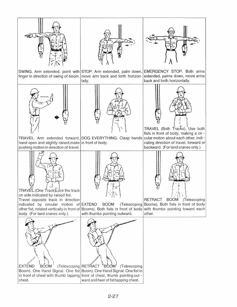
C. OPERATOR'S COMMUNICAUTION CHART (ANSI / ASME B30.5)
2-27

2-28
4-6. LIFTING THE LOAD
Always inspect hook block, loadline, and/or any load handling equipment before operation for damage or excessive wear.
Follow the recommended procedures for work site position, outrigger positioning, and control metering.
The following general instructions should be adhered to each time a lifting operation is per-formed.
WARNINGIt is important that you know the weight of any material that you attempt to handle. This can be determined by use of a dynamometer or scales.
■ STEPS TO LIFTING A LOAD
1. Determine what the total load weighs.
Note: Total load includes the weight of the material being lifted plus any material handling devices such as slings, load blocks, etc.
2. Consult the maximum load chart on your crane and determine the correct boom radius allowed based upon your load weight.
3. Rotate the boom tip until it is directly over the material to be lifted.
4. Attach loadline to material and begin operation.

2-29
4-7. ROADING THE UNIT
Never leave the work site or reposition the truck crane without fi rst securing the boom in road travel position.
Before leaving the work site or repositioning the crane at the work site, always:
1. Retract all boom. Attach block hook to storage loop on the trestle. Stow booms in a horizontal position parallel with truck frame.
2. Hoist in winch until slack is taken up.3. Fully retract all outriggers.
The outrigger should be stored in the fol-lowing manner.(1) Move the outrigger lever to pull to re-
tract the outrigger cylinders.(2) After the outrigger cylinders on both
sides have retracted fully, pull out the lock pin along the guide then hold the the handle to push in the outrigger for storage.
(3) After the outrigger has been stored entirely, return the lock pin back into place to lock the outrigger sliding arm securely. Secure lock pin with the cot-ter pin.
4. Disengage power take off (P.T.O.).5. Secure any load or lifting attachments to
the fl atbed.
Retract outriggercylinder
Push inoutrigger
Handle
Lock pin
②
①
③ Confirm that lockpin is returned towhere it was.
CAUTION

2-30
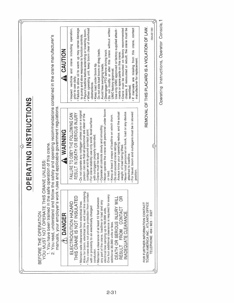
5.PLACARDS
B00M RADIUS IN FEET
BOOM RADIUS
& ANGLE
BOOM LENGTH
1ST STAGE
2ND STAGE
3RD STAGE
4TH STAGE
5TH STAGE
6TH STAGE
C-514023-V376-A1
B00M RADIUS IN FEET
BOOM RADIUS
& ANGLE
BOOM LENGTH
1ST STAGE
2ND STAGE
3RD STAGE
4TH STAGE
5TH STAGE
6TH STAGE
C-514024-V376-A1
ROPE AND REEVING MAX.LIFT IN POUNDS
KEEP AT LEAST3 WRAPS OF
LOADLINE ON DRUMAT ALL TIMES.
USE ONLY 5/16"
DIAMETER WIRE ROPEON THIS MACHINE.
MINIMUM BREAKING STRENGTH9,520 LBS.
CAUTION!
6.88
8.910111316
18.522
25.729
32.936
44
6 8,000
47.3
40.1
RATED LOADS
BOOM
(FT.)
8,0006,3005,500
4,400
8,000PART IV
4,900
8,0008,0006,3005,500
4,4004,900
3,6002,9002,400
4,9004,900
3,9004,400
3,1002,4002,0001,6001,400
2,3002,3002,3001,9001,7001,4001,200
C-514025-V376-A1
1,000900
1,4001,4001,100900800700600550500
700600550500
RADIUS
450400350350300300
ALL BOOMS RETRACTED
2ND STAGE EXTENDED
(LBS.)
3RD STAGE EXTENDED
(LBS.)
4TH STAGE EXTENDED
(LBS.)
5TH STAGE EXTENDED
(LBS.)
6TH STAGE EXTENDED
(LBS.)(LBS.)
1. RATED LOADS SHOWN ON CHART ARE MAXIMUM ALLOWABLE LOADS WITH THE OUTRIGGERS FULLY EXTENDED ON A FIRM LEVEL GROUND AND BASED ON THE ACTUAL WORKING RADIUS INCLUDING THE DEFLECTION OF THE BOOM.2. WEIGHTS OF HOOK (70Lbs.), SLINGS, AND ANY ACCESSORIES TO THE BOOM OR LOADLINE MUST BE DEDUCTED FROM THE RATED LOADS.3. WHEN A LOAD IS LIFTED IN THE VEHICLE FRONT, OPERATE THE CRANE WITH A LOAD LESS THAN 25% OF THE RATED LOADS.
HOOK
SLINGS+
LOAD
RATED LOAD
+
=
CAUTION!
RANGE DIAGRAM60
5 10 15 20 25 30 35 40 45 50
5
10
15
20
25
30
35
40
45
50
55
1ST STAGE 2ND 3RD 4TH 5TH 6TH
0
BOOM ANGLE
78°70°
60°
50°
40°
30°
20°
10°
1°
CAUTION: BOOM DEFLECTIONS NOT SHOWN.
BOOM RADIUS IN FEET FROM CENTER OF ROTATION
HEIGHT IN FEET FROM GROUND
B-523167-V376-A1
Rated Loads Chart,Operator Console,1
Range Diagram,Operator Console,1
Boom Angle RH, Boom base, 1
Boom Angle LH, Boom base, 1
2-31
1

2-32
LBSFURUKAWA UNIC
CORPORATIONTOKYO JAPAN
MADE IN JAPAN
MODEL
SPEC.
CAPACITY
SERIAL NO.
CODE NO.
8000
URV346-C Crane Model Name Plate,Column, 1
Grease, 10
Emergency, 2
Working Lamp, 1
Molybdenum grease, 1
1

2-33
1
1
1
1
1
1

2-34
1
2

2-35
CAUTION FOR TRAVELLINGCHECK TO RETRACT THE HORI-ZONTAL BEAMS COMPLETELY TO MIN.SPAN.
CHECK TO FIX THE CATCHER.
CHECK TO APPEAR “BLUE MARK” OF LOCK LEVER FULLY OUTSIDE AND NOT TO PULL OUT THE HORI-ZONTAL BEAMS
1.
2.
3.088483070
CAUTION FOR TRAVELLING, 1

2-36
16
17
9
1011
12,138
8
8
3
6
5
4
2
1
18
19
20
22
23
24
25
26
7
29
28
31
PLACARD LOCAUTION CHART
No. Part Name Part No. Q'ty1 Crane Model Name Plate 602104560 12 Placard (Raise / Lower) 080A86010 13 Placard (Hoist) 080A86020 14 Placard (Telescoping) 080A86030 15 Placard (Swing) 080B81120 16 Placard (Outrigger Street Side) 080A86050 17 Placard (Outrigger Curb Side) 080A86040 18 Placard (Grease) 080581060 109 Placard (Horn) 08J081240 1
10 Placard (Caution, O / R Operation) 08V883040 211 Placard (Hook) 08A481140 212 Placard (Boom Angle R.H.) C-514023 113 Placard (Boom Angle L.H.) C-514024 114 Placard (Rated Loads) C-514025 115 Placard (Operating Instructions) 08A481080 116 Placard (UNIC) 090B81250 2
No. Part Name Part No. Q'ty17 Placard (340) 090G81090 218 Placard (Electrocution Hazard) 088F81090 219 Placard (Danger, O / R Operation) 088F81050 220 Placard (Replacement Warning) 088F81070 221 Placard (Electrocution Hazard ) 088F81110 122 Placard (Caution, Inspect Vehicle) 08A481090 223 Placard (Danger, Two Blocking) 08A481110 224 Placard (Hydraulic Release) 08V883030 125 Placard (Working Lamp) 08V883020 126 Placard (Overwinding Alarm) 602103291 127 Placard (Range Diagram) B-523167 128 Placard (Hoisting Personnel) 08A481130 229 Placard (Ride Load Line) 08A481120 230 Placard (Molybden grease) 08AB83010 131 Placard (Caution For Travelling) 088483070 2


■MAINTENANCE SECTION

3-1
1. PERIODIC MAINTENANCEThe life of any piece of construction equipment is greatly infl uenced by operating techniques and the quality of the care it receives.Routine checks and service are essential for preventing breakdowns, maintaining perfor-mance and keeping operation costs down. Also, lubrication is an important part of any good maintenance program.Intervals on the periodic maintenance are for operating in normal conditions. If you operate your machine in diffi cult conditions, you should service it at shorter intervals.
While lubricating and/or servicing, be sure to hang a caution tag on the control lever to prevent the crane from being operated by the other personal.
CAUTION

3-2
2. PERIODIC MAINTENANCE/DAlLYDaily inspection to be made before operation.Making the inspection before operation results in using the machine safely or prevents fail-ures.
2-1. WALK-AROUND INSPECTIONFor operator personnel safety and maximum service life of the machine, make a thorough walk- around inspection before starting the engine.Inspect each part of the crane according to the following service schedule.
Device Servicing item
1 Hydraulic oil reservoir Oil leakage
2 Hydraulic pumpLoose mounting
Oil leakage
3 OutriggersCracks in welded parts
Oil leakage
4 Base Fastening tightness of crane body mounting bolts
5 Control Valve Oil leakage
6 Swing device Loose bolts and nuts
7 Hydraulic piping Oil leakage from joints
8 Topping cylinderDamage in fulcrum pin and boss
Oil leakage
9 BoomDamage of fulcrum pin and boss
Cracks in welded parts
10 Sheave pinDamage of fulcrum pin and boss
Rust on boss
11 HookRotation of hook
Damage of sheave
12 Hook latchTension of spring
Deformation and damage
13 Others Sling wire and other equipment necessary for crane operation
14 Control lever Control lever return

3-3
2-2. INSPECTION FOR FUNCTION
1. Check that each moving part of the crane operates smoothly.2. Check that the Anti- two block device operates correctly.3. Check that the warning horn switch operates correctly.4. Check that the winch brake operates correctly.

3-4
2-3. WIRE ROPE INSPECTION
Wire rope in active service should be visually inspected once every working day. A thorough inspection of such rope should be made at least once a month and dated records kept as to rope condition.Replace the rope according to the following standard.
(1) In running ropes, six randomly distributed broken wires in one rope lay, or three broken wires in one strand in one rope lay. (A rope lay is the length along the rope in which one strand makes a complete revolution around the rope.)
(2) In pendants or standing ropes, evidence of more than one broken wire in one lay.
(3) Abrasion, scrubbing, or peening causing loss of more than 1/3 of the original diameter of the outside wires.
(4) Evidence of severe corrosion.(5) Severe kinking, severe crushing, or other
damage resulting in distortion of the rope structure.
(6) Evidence of any heat damage from a torch or arc caused by contact with electrical wires.
(7) Reduction from nominal rope diameter of more than 1/64 in. (0.4 mm) for diameters 5/16 in. (8.0 mm); Marked reduction in diameter indicates dete-rioration of the core, resulting in lack of prop-er support for the load carrying strands. Excessive rope stretch or elongation may also be an indication of internal deteriora-tion.
(8) Evidence of "bird caging" or other distortion resulting in some members of the rope struc-ture carrying more load than others.
(9) Noticeable rusting or development of broken wires in the vicinity of attachments. (Note: If this condition is localized in an operating rope and the section in question can be eliminated by making a new attachment, this can be done rather than replacing the entire rope.)

3-5
When passing a wire rope end through the wire socket, be sure to pass it as indicated by the arrow on the wire socket. If it is passed in the opposite direction, the wire rope will be kept bent, which results in a shorter rope life.Do not forget to mount the wedge and wire clip.The arrow on the wire socket must face out-ward as shown above when it is mounted on the boom.
★ Adjustment when wire rope is twisted.
Under tension, wire rope turns in the untwisting direction. If two or more wire ropes are hooked together, they tend to be twisted, particularly while they are new. They will be free of twisting as they become used.If the wire ropes are twisted, adjust them as described below:① Extend the boom fully.② Set the boom to an angle of about 65°.③ Free the boom of load.④ Then, check how many turns the wire ropes are twisted.⑤ Remove the wire socket, and turn the wire
socket in the untwisting direction as many turns as the wire ropes were twisted multiplied by the number of wire ropes. Remember, however, that the wire socket may be turned only 4 turns at a time.
⑥ Attach the wire socket, wind the hoist to full hoist and unwind. Repeat this a few times, and see’ if the wire ropes are no longer twist-ed. If they were still twisted, repeat the same ad-justment.
CAUTION

3-6
3.PERIODIC MAINTENANCE/WEEKLYLUBRICATE THE FITTINGS
Thoroughly clean grease nipples before lubrication.When supplying grease into a bushing, be sure to pump the grease gun until old grease is forced out of the bushing.
①
⑦
② ③ ④⑤
⑥
Application Lubricant Procedure
① Boom slide plate [undersides of inner boom] Molybdenum grease Brush
② Boom foot pin Chassis grease Grease gun
③ Topping cylinder upper support pin Chassis grease Grease gun
④ Topping cylinder lower support pin Chassis grease Grease gun
⑤ Winch drum gear Chassis grease Grease gun
⑥ Rotation gear teeth Chassis grease Brush
⑦ Control lever (pins on both sides and bearing) Chassis grease Grease gun

3-7
4.PERIODIC MAINTENANCE/MONTHLY4-1. LUBRICATE SWING BEARING
4-2. CHECK GEAR OIL LEVEL
Use chassis grease.Be sure to fi ll grease into the bearing while turning it.
for winch gear box and swing gear box.
Grease nipple
Vent plugWinch gear box
Gear oilfiller port
Lavel gauge
Vent plugGear oilfiller port
Lavel gauge
Swing gear box
Level gauge
Upper limit
Lower limitOil surface
1. Remove the vent plug for fi ller port.2. Fill oil up to the middle of the oil level
gauge.3. Install the vent plug.
1. Remove the vent plug for fi ller port.2. Fill oil up to a level between upper and
lower limit marks of the oil level gauge. Check oil level not by tighten up the oil level gauge cap but by just inserting the gauge in the fi ller port.
3. Install the vent plug.
★ WINCH GEAR BOX ★ SWING GEAR BOX

3-8
4-3. LUBRICATE WIRE ROPE FOR BOOM EXTENSION
Spray the rope grease suffi ciently to the wire ropes with the boom fully extended.

3-9
5.PERIODIC MAINTENANCE/ANNUAL5-1. CHANGE GEAR OIL
★ The gear oil should be changed after 6 months of initial operation, and once a year there-after.
for winch gear box and swing gear box
CAUTIONHot oil and components can cause injury.Do not allow hot oil or components to contact skin.
1. Remove the drain plug and drain oil. lnstall the drain plug.
2. Remove the vent plug for fi ller port.3. Fill new oil up to the middle of the oil
level gauge.4. Install the vent plug.
1. Remove the drain plug and drain oil. lnstall the drain plug.
2. Remove the vent plug for fi ller port.3. Fill oil up to a level between upper and
lower limit marks of the oil level gauge. Check oil level not by tighten up the oil level gauge cap but by just inserting the gauge in the fi ller port.
4. Install the vent plug.
Drain plug
Vent plugWinch gear box
Gear oilfiller port
Lavel gauge
Drain plug
Vent plugGear oilfiller port
Lavel gauge
Swing gear box
★ WINCH GEAR BOX ★ SWING GEAR BOX

3-10
5-2. CHECKING SWING BEARING MOUNTING BOLTS
When the swing device of this machine gives out unusual noise during operation or traveling, or when a gap is produced on the mounting sur-face, contact our authorized service shop for re-pairing.
Mounting bolts

3-11
6. PERIODIC MAINTENANCE/REPLACEMENT OF EXPENDABLE PARTS
Replace the following parts periodically in order that the strength and quality of the original machine may be maintained.When you replace the above parts, contact UNIC CORPORATION or the authorized deal-er.

■ OTHERS
4-1
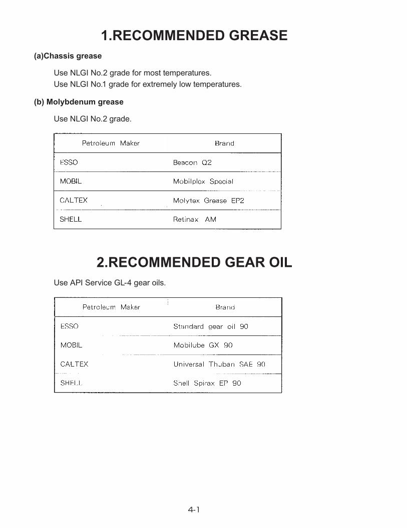
1.RECOMMENDED GREASE(a)Chassis grease
Use NLGI No.2 grade for most temperatures.Use NLGI No.1 grade for extremely low temperatures.
(b) Molybdenum grease
Use NLGI No.2 grade.
2.RECOMMENDED GEAR OILUse API Service GL-4 gear oils.

4-2
3. RECOMMENDED HYDRAULIC OILUse industrial- type hydraulic oil; ISO VG 46 for temperatures above 32F. ISO VG 22 for temperatures below 32F.

4-3
4.HYDRAULIC CIRCUIT
STRAINER
PUMP
OIL RESERVERCONTROL VALVE
2990psi
BOOM
HOIST
EXTENTION
SWING
FILTERCOUNTERBALANCE VALVE
HOISTMOTOR
TWO-BLOCKVALVE
COUNTERBALANCE VALVE
CURBSIDE
STREETSIDE
PILOTCHECK VALVE
OUTRIGGERCYLINDER
SLEWING MOTOR
BOOM TOPPINGCYLINDER
TELESCOPINGCYLINDER
G.PRc1/4(PT1/4)

4-4
5.EMERGENCY RELEASEWhen the crane can not be operated due to a malfunction in the ANTI TWO-BLOCK SYS-TEM and/or in the AUTOMATIC OVER-LOAD PROTECTION SYSTEM, release the auto-matic stop and store the crane.Remove the cover of the alarm and turn the switch [OFF] to release it.When the crane fails to make raising/lowering because the boom has gone beyond the maxi-mum boom angle as a result that the boom was raised with the engine speed excessively increased by the accelerator at a proximity of maximum boom angle, turn off the emergency release switch to lower the boom and then turn it on again to restore crane operation.


HEAD OFFICE : Nihonbashi nishikawa Bldg, 5-3, Nihonbashi 1-chome, Chuo-ku, Tokyo 103-0027, Japan