operator’s manual supplement 96-0202 revision e...
TRANSCRIPT

,
Haas Automation Inc.2800 Sturgis Road
Oxnard, CA 93030-8933U.S.A. | HaasCNC.com
To get translated versions of this Manual:1. Go to www.HaasCNC.com2. See Owner Resources (bottom of page)3. Select Manuals and Documentation
© 2013 Haas Automation, Inc. All Rights Reserved. Copy by Permission Only. Copyright Strictly Enforced.
UMC-750
Operator’s Manual Supplement96-0202
Revision EOctober 2013
EnglishOriginal Instructions


i
© 2013 Haas Automation, Inc.
All rights reserved. No part of this publication may be reproduced, stored in a retrieval system, ortransmitted, in any form, or by any means, mechanical, electronic, photocopying, recording, orotherwise, without the written permission of Haas Automation, Inc. No patent liability is assumed withrespect to the use of the information contained herein. Moreover, because Haas Automation strivesconstantly to improve its high-quality products, the information contained in this manual is subject tochange without notice. We have taken every precaution in the preparation of this manual;nevertheless, Haas Automation assumes no responsibility for errors or omissions, and we assume noliability for damages resulting from the use of the information contained in this publication.

ii

iii
LIMITED WARRANTY CERTIFICATE
Haas Automation, Inc.
Covering Haas Automation, Inc. CNC Equipment
Effective September 1, 2010
Haas Automation Inc. (“Haas” or “Manufacturer”) provides a limited warranty on all newmills, turning centers, and rotary machines (collectively, “CNC Machines”) and theircomponents (except those listed below under Limits and Exclusions of Warranty)(“Components”) that are manufactured by Haas and sold by Haas or its authorizeddistributors as set forth in this Certificate. The warranty set forth in this Certificate is alimited warranty, it is the only warranty by Manufacturer, and is subject to the terms andconditions of this Certificate.
Limited Warranty Coverage
Each CNC Machine and its Components (collectively, “Haas Products”) are warranted byManufacturer against defects in material and workmanship. This warranty is provided onlyto an end-user of the CNC Machine (a “Customer”). The period of this limited warranty isone (1) year. The warranty period commences on the date the CNC Machine is installed atthe Customer’s facility. Customer may purchase an extension of the warranty period froman authorized Haas distributor (a “Warranty Extension”), any time during the first year ofownership.
Repair or Replacement Only
Manufacturer’s sole liability, and Customer’s exclusive remedy under this warranty, withrespect to any and all Haas products, shall be limited to repairing or replacing, at thediscretion of the Manufacturer, the defective Haas product.
Disclaimer of Warranty
This warranty is Manufacturer’s sole and exclusive warranty, and is in lieu of all otherwarranties of whatever kind or nature, express or implied, written or oral, including, but notlimited to, any implied warranty of merchantability, implied warranty of fitness for aparticular purpose, or other warranty of quality or performance or noninfringement. All suchother warranties of whatever kind are hereby disclaimed by Manufacturer and waived byCustomer.

iv
Limits and Exclusions of Warranty
Components subject to wear during normal use and over time, including, but not limited to,paint, window finish and condition, light bulbs, seals, wipers, gaskets, chip removal system(e.g., augers, chip chutes), belts, filters, door rollers, tool changer fingers, etc., are excludedfrom this warranty. Manufacturer’s specified maintenance procedures must be adhered toand recorded in order to maintain this warranty. This warranty is void if Manufacturerdetermines that (i) any Haas Product was subjected to mishandling, misuse, abuse,neglect, accident, improper installation, improper maintenance, improper storage, orimproper operation or application, (ii) any Haas Product was improperly repaired orserviced by Customer, an unauthorized service technician, or other unauthorized person,(iii) Customer or any person makes or attempts to make any modification to any HaasProduct without the prior written authorization of Manufacturer, and/or (iv) any HaasProduct was used for any non-commercial use (such as personal or household use). Thiswarranty does not cover damage or defect due to an external influence or matters beyondthe reasonable control of Manufacturer, including, but not limited to, theft, vandalism, fire,weather condition (such as rain, flood, wind, lightning, or earthquake), or acts of war orterrorism.
Without limiting the generality of any of the exclusions or limitations described in thisCertificate, this warranty does not include any warranty that any Haas Product will meet anyperson’s production specifications or other requirements, or that operation of any HaasProduct will be uninterrupted or error-free. Manufacturer assumes no responsibility withrespect to the use of any Haas Product by any person, and Manufacturer shall not incurany liability to any person for any failure in design, production, operation, performance, orotherwise of any Haas Product, other than repair or replacement of same as set forth in thewarranty above.
Limitation of Liability and Damages
Manufacturer will not be liable to Customer or any other person for any compensatory,incidental, consequential, punitive, special, or other damage or claim, whether in an actionin contract, tort, or other legal or equitable theory, arising out of or related to any Haasproduct, other products or services provided by Manufacturer or an authorized distributor,service technician, or other authorized representative of Manufacturer (collectively,“authorized representative”), or the failure of parts or products made by using any HaasProduct, even if Manufacturer or any authorized representative has been advised of thepossibility of such damages, which damage or claim includes, but is not limited to, loss ofprofits, lost data, lost products, loss of revenue, loss of use, cost of down time, businessgood will, any damage to equipment, premises, or other property of any person, and anydamage that may be caused by a malfunction of any Haas product. All such damages andclaims are disclaimed by Manufacturer and waived by Customer. Manufacturer’s soleliability, and Customer’s exclusive remedy, for damages and claims for any causewhatsoever shall be limited to repair or replacement, at the discretion of Manufacturer, ofthe defective Haas Product as provided in this warranty.

v
Customer has accepted the limitations and restrictions set forth in this Certificate, including,but not limited to, the restriction on its right to recover damages, as part of its bargain withManufacturer or its Authorized Representative. Customer realizes and acknowledges thatthe price of the Haas Products would be higher if Manufacturer were required to beresponsible for damages and claims beyond the scope of this warranty.
Entire Agreement
This Certificate supersedes any and all other agreements, promises, representations, orwarranties, either oral or in writing, between the parties or by Manufacturer with respect tosubject matter of this Certificate, and contains all of the covenants and agreementsbetween the parties or by Manufacturer with respect to such subject matter. Manufacturerhereby expressly rejects any other agreements, promises, representations, or warranties,either oral or in writing, that are in addition to or inconsistent with any term or condition ofthis Certificate. No term or condition set forth in this Certificate may be modified oramended, unless by a written agreement signed by both Manufacturer and Customer.Notwithstanding the foregoing, Manufacturer will honor a Warranty Extension only to theextent that it extends the applicable warranty period.
Transferability
This warranty is transferable from the original Customer to another party if the CNCMachine is sold via private sale before the end of the warranty period, provided that writtennotice thereof is provided to Manufacturer and this warranty is not void at the time oftransfer. The transferee of this warranty will be subject to all terms and conditions of thisCertificate.
Miscellaneous
This warranty shall be governed by the laws of the State of California without application ofrules on conflicts of laws. Any and all disputes arising from this warranty shall be resolvedin a court of competent jurisdiction located in Ventura County, Los Angeles County, orOrange County, California. Any term or provision of this Certificate that is invalid orunenforceable in any situation in any jurisdiction shall not affect the validity or enforceabilityof the remaining terms and provisions hereof, or the validity or enforceability of theoffending term or provision in any other situation or in any other jurisdiction.

vi
Customer Feedback
If you have concerns or questions regarding this Operator’s Manual, please contact us onour website, www.HaasCNC.com. Use the “Contact Haas” link and send your commentsto the Customer Advocate.
You also can find an electronic copy of this manual and other useful information on ourwebsite under the “Owner’s Resources” tab. Join Haas owners online and be a part of thegreater CNC community at these sites:

vii
Customer Satisfaction Policy
Dear Haas Customer,
Your complete satisfaction and goodwill are of the utmost importance to both HaasAutomation, Inc. and the Haas distributor (HFO) where you purchased your equipment.Normally, your HFO will rapidly resolve any concerns you have about your salestransaction or the operation of your equipment.
However, if your concerns are not resolved to your complete satisfaction, and you havediscussed your concerns with a member of the HFO’s management, the General Manager,or the HFO’s owner directly, please do the following:
Contact Haas Automation’s Customer Service Advocate at 805-988-6980. So that we mayresolve your concerns as quickly as possible, please have the following informationavailable when you call:
• Your company name, address, and phone number• The machine model and serial number• The HFO name, and the name of your latest contact at the HFO• The nature of your concern
If you wish to write Haas Automation, please use this address:
Haas Automation, Inc. U.S.A.2800 Sturgis RoadOxnard CA 93030Att: Customer Satisfaction Manageremail: [email protected]
Once you contact the Haas Automation Customer Service Center, we will make every effortto work directly with you and your HFO to quickly resolve your concerns. At HaasAutomation, we know that a good Customer-Distributor-Manufacturer relationship will helpensure continued success for all concerned.
International:
Haas Automation, EuropeMercuriusstraat 28, B-1930Zaventem, Belgiumemail: [email protected]
Haas Automation, AsiaNo. 96 Yi Wei Road 67,Waigaoqiao FTZShanghai 200131 P.R.C.email: [email protected]

viii

ix
Declaration of Conformity
Product: CNC Milling Centers (Vertical and Horizontal)*
*Including all options factory- or field-installed by a certified Haas Factory Outlet (HFO)
Manufactured By: Haas Automation, Inc.
2800 Sturgis Road, Oxnard, CA 93030 805-278-1800
We declare, in sole responsibility, that the above-listed products, to which this declarationrefers, comply with the regulations as outlined in the CE directive for Machining Centers:
• Machinery Directive 2006/42/EC• Electromagnetic Compatibility Directive 2004/108/EC• Low Voltage Directive 2006/95/EC• Additional Standards:
– EN 60204-1:2006/A1:2009– EN 614-1:2006+A1:2009– EN 894-1:1997+A1:2008– EN 13849-1:2008/AC:2009– EN 14121-1:2007
RoHS: COMPLIANT by Exemption per producer documentation. Exempt by:
a) Large scale stationary industrial toolb) Monitoring and control systemsc) Lead as an alloying element in steel, aluminum, and copper
Person authorized to compile technical file:
Patrick GorisAddress: Haas Automation Europe
Mercuriusstraat 28, B-1930Zaventem, Belgium

x
USA: Haas Automation certifies this machine to be in compliance with the OSHA and ANSIdesign and manufacturing standards listed below. Operation of this machine will becompliant with the below-listed standards only as long as the owner and operator continueto follow the operation, maintenance, and training requirements of these standards.
• OSHA 1910.212 - General Requirements for All Machines• ANSI B11.5-1983 (R1994) Drilling, Milling, and Boring Machines• ANSI B11.19-2003 Performance Criteria for Safeguarding• ANSI B11.23-2002 Safety Requirements for Machining Centers and Automatic
Numerically Controlled Milling, Drilling, and Boring Machines• ANSI B11.TR3-2000 Risk Assessment and Risk Reduction - A Guideline to Estimate,
Evaluate, and Reduce Risks Associated with Machine Tools
CANADA: As the original equipment manufacturer, we declare that the listed productscomply with regulations as outlined in the Pre-Start Health and Safety Reviews Section 7of Regulation 851 of the Occupational Health and Safety Act Regulations for IndustrialEstablishments for machine guarding provisions and standards.
Further, this document satisfies the notice-in-writing provision for exemption from Pre-Startinspection for the listed machinery as outlined in the Ontario Health and Safety Guidelines,PSR Guidelines dated April 2001. The PSR Guidelines allow that notice in writing from theoriginal equipment manufacturer declaring conformity to applicable standards is acceptablefor the exemption from Pre-Start Health and Safety Review.
Original Instructions
ETL LISTEDCONFORMS TONFPA STD 79
ANSI/UL STD 508UL SUBJECT 2011
CERTIFIED TO CAN/CSA STD C22.2 N O.73
9 7 0 0 8 4 5
All Haas CNC machine tools carry the ETL Listed mark, certifying that they conform to the NFPA 79 Electrical Standard for Industrial Machinery and the Canadian equivalent, CAN/CSA C22.2 No. 73. The ETL Listed and cETL Listed marks are awarded to products that have successfully undergone testing by Intertek Testing Services (ITS), an alternative to Underwriters' Laboratories.
The ISO 9001:2008 certification from ISA, Inc. (an ISO registrar) serves as an impartial appraisal of Haas Automation’s quality management system. This achievement affirms Haas Automation’s conformance with the standards set forth by the International Organization for Standardization, and acknowledges the Haas commitment to meeting the needs and requirements of its customers in the global marketplace.

xi
How to Use This Manual
To get the maximum benefit of your new Haas machine, read this manual thoroughly andrefer to it often. The content of this manual is also available on your machine control underthe HELP function.
IMPORTANT: Before you operate the machine, read and understand the Operator’sManual Safety chapter.
Declaration of WarningsThroughout this manual, important statements are set off from the main text with an iconand an associated signal word: “Danger,” “Warning,” “Caution,” or “Note.” The icon andsignal word indicate the severity of the condition or situation. Be sure to read thesestatements and take special care to follow the instructions.
Description Example
Danger means that there is a condition or situation that will cause death or severe injury if you do not follow the instructions given. DANGER: No step. Risk of electrocution, bodily
injury, or machine damage. Do not climb or stand on this area.
Warning means that there is a condition or situation that will cause moderate injury if you do not follow the instructions given. WARNING: Never put your hands between the
tool changer and the spindle head.
Caution means that minor injury or machine damage could occur if you do not follow the instructions given. You may also have to start a procedure over if you do not follow the instructions in a caution statement.
CAUTION: Power down the machine before you do maintenance tasks.
Note means that the text gives additional information, clarification, or helpful hints.
NOTE: Follow these guidelines if the machine is equipped with the optional extended Z-clearance table.

xii
Text Conventions Used in this Manual
Description Text Example
Code Block text gives program examples. G00 G90 G54 x0. Y0.;
A Control Button Reference gives the name of a control key or button that you are to press.
Press [CYCLE START].
A File Path describes a sequence of file system directories.
Service > Documents and Software >...
A Mode Reference describes a machine mode. MDI
A Screen Element describes an object on the machine’s display that you interact with.
Select the SYSTEM tab.
System Output describes text that the machine control displays in response to your actions.
PROGRAM END
User Input describes text that you should enter into the machine control.
G04 P1.;

Contents
Chapter 1 Introduction . . . . . . . . . . . . . . . . . . . . . . . . . . . . 11.1 Overview . . . . . . . . . . . . . . . . . . . . . . . . . . . 11.2 Axis Definitions . . . . . . . . . . . . . . . . . . . . . . . . 21.3 UMC-750 Specifications. . . . . . . . . . . . . . . . . . . . 3
Chapter 2 Integrated Coolant Tank . . . . . . . . . . . . . . . . . . . . . 52.1 Introduction . . . . . . . . . . . . . . . . . . . . . . . . . . 5
2.1.1 Coolant Pump Location . . . . . . . . . . . . . . . . 52.2 Coolant Tank Clean-Out. . . . . . . . . . . . . . . . . . . . 6
Chapter 3 Wireless Intuitive Probing System (WIPS). . . . . . . . . . . . 93.1 UMC WIPS Basics . . . . . . . . . . . . . . . . . . . . . . 9
Chapter 4 Machine Rotary Zero Point (MRZP) Offsets . . . . . . . . . . 114.1 Introduction . . . . . . . . . . . . . . . . . . . . . . . . . . 11
4.1.1 Check MRZP Offsets with WIPS . . . . . . . . . . . 114.2 Parameter Change . . . . . . . . . . . . . . . . . . . . . . 13
Chapter 5 G234 - Tool Center Point Control (TCPC) . . . . . . . . . . . 155.1 Introduction . . . . . . . . . . . . . . . . . . . . . . . . . . 15
Chapter 6 G254 - Dynamic Work Offset (DWO) . . . . . . . . . . . . . . 196.1 Introduction . . . . . . . . . . . . . . . . . . . . . . . . . . 19
Chapter 7 Setting Work and Tool Offsets . . . . . . . . . . . . . . . . . 237.1 Set the B-Axis Work Offset . . . . . . . . . . . . . . . . . . 237.2 Set the C-Axis Work Offset . . . . . . . . . . . . . . . . . . 237.3 Set the X-, Y-, and Z-Axis Work Offsets Manually . . . . . . 247.4 Set the X-, Y-, and Z-Axis Work Offsets with WIPS . . . . . . 28
xiii

Chapter 8 C-Axis Rotary Unwind and Setting 247 . . . . . . . . . . . . 318.1 C-Axis Rotary Unwind . . . . . . . . . . . . . . . . . . . . . 318.2 247 - Simultaneous XYZ Motion in Tool Change . . . . . . . 31
Chapter 9 Other Information . . . . . . . . . . . . . . . . . . . . . . . . 339.1 Machine and Post-Processor Information . . . . . . . . . . . 33
9.1.1 G141 3D+ Cutter Compensation (Group 07) . . . . . 35
Index . . . . . . . . . . . . . . . . . . . . . . . . . . . . . . . 39
xiv

Introduction
Chapter 1: Introduction
1.1 OverviewThis operator’s manual supplement describes the unique features and functions of theUMC-750. Refer to the Mill Operator’s Manual (P/N 96-8000) for machine and controloperation.
Specific details about the UMC-750 itself, including information that is beyond the scope ofthis document, can be found at www.HaasCNC.com.
1

1.2 Axis DefinitionsThis diagram illustrates the (5) axes available on the UMC-750.
B
C-35°
+110°
- +
2
Introduction
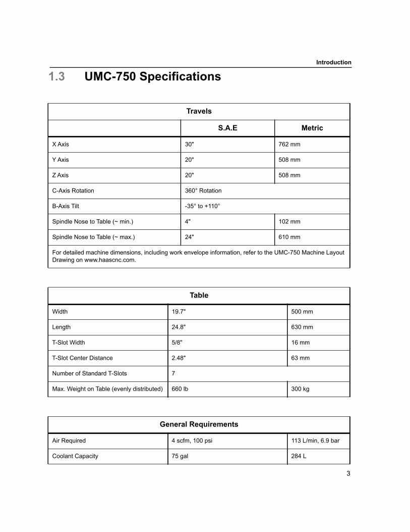
1.3 UMC-750 Specifications
Travels
S.A.E Metric
X Axis 30" 762 mm
Y Axis 20" 508 mm
Z Axis 20" 508 mm
C-Axis Rotation 360° Rotation
B-Axis Tilt -35° to +110°
Spindle Nose to Table (~ min.) 4" 102 mm
Spindle Nose to Table (~ max.) 24" 610 mm
For detailed machine dimensions, including work envelope information, refer to the UMC-750 Machine Layout Drawing on www.haascnc.com.
Table
Width 19.7" 500 mm
Length 24.8" 630 mm
T-Slot Width 5/8" 16 mm
T-Slot Center Distance 2.48" 63 mm
Number of Standard T-Slots 7
Max. Weight on Table (evenly distributed) 660 lb 300 kg
General Requirements
Air Required 4 scfm, 100 psi 113 L/min, 6.9 bar
Coolant Capacity 75 gal 284 L
3

Power Requirement, Low Voltage 195-260 VAC / 100A
Power Requirement, High Voltage 354-488 VAC / 50A
Machine Weight 18,000 lb 8165 kg
Standard Features
Tool Center Point Control (TCPC), Dynamic Work Offsets (DWO), Remote Jog Handle*, Second Home*, Macros*, Spindle Orientation (SO)*, Coordinate Rotation and Scaling (COORD)*, TSC-Ready, Wireless Intuitive Probing System (WIPS)*Refer to the Mill Operator’s Manual (96-8000) for information on these features.
General Requirements
4

Integrated Coolant Tank
Chapter 2: Integrated Coolant Tank
2.1 IntroductionThe UMC-750 coolant tank is integrated into the machine base.
F2.1: UMC -750 Integrated Coolant Tank
2.1.1 Coolant Pump Location
The coolant pumps are on the tool changer side of the machine, behind the chip conveyor.The standard coolant box filter is mounted below the standard coolant pump.
5

Coolant Pump Location
F2.2: UMC-750 Coolant Pump Location: [1] Chip Tray, [2] Gate Filter, [3] Coolant Box Filter, [4] Standard Coolant Pump, [5] TSC Coolant Pump
2.2 Coolant Tank Clean-OutTo clean out the coolant tank:
1. Remove the coolant pumps.
2. Remove and empty the coolant box filter.
3. Remove and empty the chip tray.
4. Remove and clean the gate filter.
5. Use a wet/dry vacuum or similar device to remove the used coolant from the tank.
6. For more thorough cleaning, open the coolant tank access panels in the bottom of the work space.
2
4
5
3
1
6

Integrated Coolant Tank
F2.3: Coolant Tank Access Panels
7. Add coolant to the tank and install the gate filter, coolant box filter, chip tray, and coolant pumps. Install the coolant tank access panels if you removed them.
7

Coolant Pump Location
8
Wireless Intuitive Probing System (WIPS)
Chapter 3: Wireless Intuitive Probing System (WIPS)
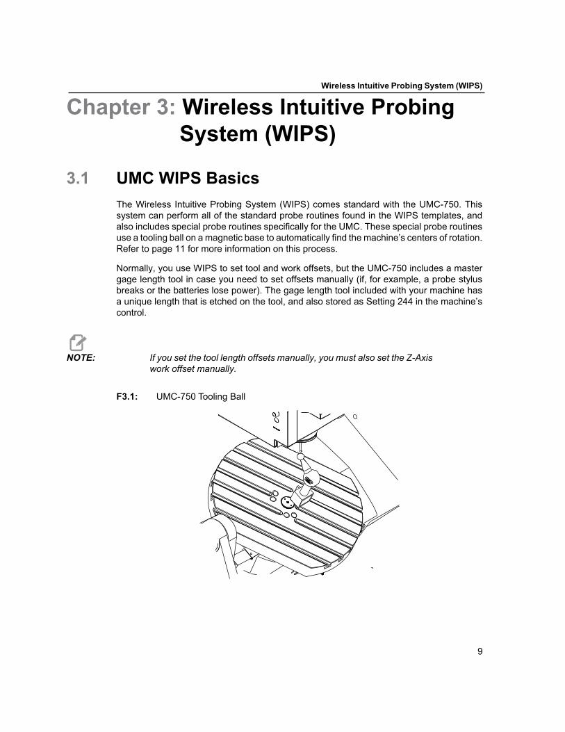
3.1 UMC WIPS BasicsThe Wireless Intuitive Probing System (WIPS) comes standard with the UMC-750. Thissystem can perform all of the standard probe routines found in the WIPS templates, andalso includes special probe routines specifically for the UMC. These special probe routinesuse a tooling ball on a magnetic base to automatically find the machine’s centers of rotation.Refer to page 11 for more information on this process.
Normally, you use WIPS to set tool and work offsets, but the UMC-750 includes a mastergage length tool in case you need to set offsets manually (if, for example, a probe stylusbreaks or the batteries lose power). The gage length tool included with your machine hasa unique length that is etched on the tool, and also stored as Setting 244 in the machine’scontrol.
NOTE: If you set the tool length offsets manually, you must also set the Z-Axiswork offset manually.
F3.1: UMC-750 Tooling Ball
9

10

Machine Rotary Zero Point (MRZP) Offsets
Chapter 4: Machine Rotary Zero Point (MRZP) Offsets
4.1 IntroductionThe Machine Rotary Zero Point (MRZP) Offsets are control parameters that define thecenters of rotation for the rotary table relative to the home positions of the linear axes.Parameters 1306, 1307, and 1308 define:
1306 – Machine Rotary Zero Point X Offset
The location of the B-Axis rotary center point, relative to the X-Axis home position.
1307 – Machine Rotary Zero Point Y Offset
The location of the C-Axis rotary center point, relative to the Y-Axis home position.
1308 – Machine Rotary Zero Point Z Offset
The location of the B-Axis rotary center point, relative to the Z-Axis home position.
The value stored in each of these parameters is the distance from the home position of alinear axis to the center of rotation of a rotary axis. The units are in inches, scaled by10,000. For example, the default value for 1306 is -150000, representing an offset of -15.0"from machine X Zero. These parameter values are always in inches, regardless of the unitsselected in Setting 9.
The initial MRZP offsets are set at the factory. Over time, you may need to check and adjustthese parameters, due to environmental factors, machine use, or in the event of a machinecrash. This section tells you how to make sure the MRZP offsets are correct.
NOTE: These instructions assume that the probe system is installed andcorrectly calibrated. Refer to the Haas WIPS Manual (96-10002) forthe calibration procedure.
4.1.1 Check MRZP Offsets with WIPS
The MRZP offsets can change over time. To make sure the UMC-750 MRZP Offsets arecorrect:
11

Check MRZP Offsets with WIPS
1. Record the original value of Parameter 1314, and then change it to 0. Refer to page 13 for more information on changing parameter values.
WARNING: Parameters define machine operations in very specific ways. If youmust change parameters, change only those for which you havespecific and explicit factory instructions, such as those given here.
2. Place the tooling ball on the table.
IMPORTANT: To make sure the tooling ball post does not interfere with the probe,position the ball post at an angle of approximately 45 degrees to the XAxis.
F4.1: Tooling Ball Set at 45 Degrees Relative to X
3. Place the work probe in the spindle.
4. Position the work probe over the gage ball.
5. Press [MDI/DNC]. Press [PROGRAM], and then select the VQC tab.
6. Highlight MRZP SET from the VQC Menu, and then press [ENTER]. 7. Highlight FINISH MRZP SET, and then press [ENTER]. 8. Follow the prompts to generate the probe program. Enter MDI mode and press
[CYCLE START].
X~45°
12

Machine Rotary Zero Point (MRZP) Offsets
9. The probe automatically places values in macro variables 106 through 108 and 121 through 123. These variables show the machine rotary zero point axis travel distance from the home position in the X, Y, and Z Axes.
10. If the MRZP locations have changed through foundation settling or other external influences on the machine, enter the values from macro variables 106, 107, and 108 into Parameters 1306, 1307, and 1308. Remember that 10 units = 0.001".
11. Change Parameter 1314 back to its original value.
4.2 Parameter Change
WARNING: Parameters define machine operations in very specific ways. Neverchange a parameter, except under explicit factory instructions.Incorrectly set parameters can cause severe damage to your machineand void the warranty.
1. Change Setting 7 to OFF.a. Press [SETTING/GRAPHIC] until the Settings menu appears.b. Press [7], and then press the [DOWN] cursor arrow.
c. Press the [RIGHT] cursor arrow to change the setting to OFF.
d. Press[ ENTER] to save the change.
2. Press [EMERGENCY STOP].3. Press [PARAMETER/DIAGNOSTIC].4. Type the number of the parameter that you want to change.
5. Press the [DOWN] cursor arrow.
6. Record the parameter’s current value, in case you need to change it back.
7. Type the new parameter value.
8. Press [ENTER] to save the change.
9. Repeat steps 3 through 7 for any other parameters that you need to change.
10. Reset [EMERGENCY STOP].11. Press [RESET].12. Change Setting 7 back to ON.
13

Check MRZP Offsets with WIPS
14

G234 - Tool Center Point Control (TCPC)
Chapter 5: G234 - Tool Center Point Control (TCPC)
5.1 IntroductionG234 Tool Center Point Control (TCPC) is a software feature in the Haas CNC control thatallows a machine to correctly run a contouring 4- or 5-axis program when the workpiece isnot located in the exact location specified by a CAM-generated program. This eliminatesthe need to repost a program from the CAM system when the programmed and the actualworkpiece locations are different.
The Haas CNC control combines the known centers of rotation for the rotary table (MRZP)and the location of the workpiece (e.g., active work offset G54) into a coordinate system.TCPC makes sure that this coordinate system remains fixed relative to the table; when therotary axes rotate, the linear coordinate system rotates with them. Like any other worksetup, the workpiece must have a work offset applied to it. This tells the Haas CNC controlwhere the workpiece is located on the machine table.
The conceptual example and illustrations in this section represent a line segment from afull 4- or 5-axis program.
NOTE: For clarity, the illustrations in this section do not depict workholding.Also, as conceptual, representative drawings, they are not to scaleand may not depict the exact axis motion described in the text.
The straight line edge highlighted in Figure F5.1 is defined by point (X0, Y0, Z0) and point(X0, Y1, Z0). Movement along the Y Axis is all that is required for the machine to create thisedge. The location of the workpiece is defined by work offset G54.
15

F5.1: G234 and G54
In Figure F5.2, the B and C Axes have been rotated 15 degrees each. To create the sameedge, the machine will need to make an interpolated move with the X, Y, and Z Axes.Without TCPC, you would need to repost the CAM program for the machine to correctlycreate this edge.
F5.2: G234 with TCPC Off and the B and C Axes Rotated
TCPC is invoked in Figure F5.3. The Haas CNC control knows the centers of rotation forthe rotary table (MRZP), and the location of the workpiece (active work offset G54). Thisdata is used to produce the desired machine motion from the original CAM-generatedprogram. The machine will follow an interpolated X-Y-Z path to create this edge, eventhough the program simply commands a single-axis move along the Y Axis.
X0, Y0, Z0
(G54)
X0, Y1, Z0
X
Y
Z
16

G234 - Tool Center Point Control (TCPC)
F5.3: G234 with TCPC On and the B and C Axes Rotated
G234 Program Example
%O00003 (TCPC SAMPLE)G20G00 G17 G40 G80 G90 G94 G98G53 Z0.T1 M06G00 G90 G54 B47.137 C116.354 (POSITION ROTARY AXES)G00 G90 X-0.9762 Y1.9704 S10000 M03 (POSITION LINEAR AXES)G234 H01 Z1.0907 (TCPC ON WITH LENGTH OFFSET 1, APPROACH IN Z-AXIS)G01 X-0.5688 Y1.1481 Z0.2391 F40.X-0.4386 Y0.8854 Z-0.033X-0.3085 Y0.6227 Z-0.3051X-0.307 Y0.6189 Z-0.3009 B46.784 C116.382X-0.3055 Y0.6152 Z-0.2966 B46.43 C116.411X-0.304 Y0.6114 Z-0.2924 B46.076 C116.44X-0.6202 Y0.5827 Z-0.5321 B63.846 C136.786X-0.6194 Y0.5798 Z-0.5271 B63.504 C136.891X-0.8807 Y0.8245 Z-0.3486X-1.1421 Y1.0691 Z-0.1701X-1.9601 Y1.8348 Z0.3884G49 (TCPC OFF)G00 G53 Z0.G53 B0. C0.G53 Y0.M30%
G234 Programmer’s Notes
X0, Y1, Z0
X0, Y0, Z0
17

These key presses and program codes will cancel G234:
• [EMERGENCY STOP]• [RESET]• [HANDLE JOG]• [LIST PROGRAM]• M02 – Program End• M30 – Program End and Reset• G43 – Tool Length Compensation +• G44 – Tool Length Compensation -• G49 – G43 / G44 / G143 Cancel
These codes will NOT cancel G234:
• M00 – Program Stop• M01 – Optional Stop
These key presses and program codes impact G234:
• G234 invokes TCPC and cancels G43. • When using tool length compensation, either G43 or G234 must be active. G43 and
G234 cannot be active at the same time.• G234 cancels the previous H-code. An H-code must therefore be placed on the same
block as G234. • G234 cannot be used at the same time as G254 (DWO).
These codes ignore 234:
• G28 – Return to Machine Zero Through Optional Reference Point• G29 – Move to Location Thru G29 Reference Point• G53 – Non-Modal Machine Coordinate Selection• M06 – Tool Change
G234 (TCPC) is intended for simultaneous 4- and 5-axis contouring programs. An activework offset (G54, G55, etc.) is required to use G234.
18

G254 - Dynamic Work Offset (DWO)
Chapter 6: G254 - Dynamic Work Offset (DWO)
6.1 IntroductionG254 Dynamic Work Offset (DWO) is similar to TCPC, except that it is designed for usewith 3+1 or 3+2 positioning, not for simultaneous 4- or 5-axis machining. If the programdoes not make use of the B and C Axes, there is no need to use DWO.
CAUTION: The B-Axis value of the work offset you use with G254 MUST be zero.
With DWO, you no longer need to set the workpiece in the exact position as programmedin the CAM system. DWO applies the appropriate offsets to account for the differencesbetween the programmed workpiece location and the actual workpiece location. Thiseliminates the need to repost a program from the CAM system when the programmed andactual workpiece locations are different.
The control knows the centers of rotation for the rotary table (MRZP) and the location of theworkpiece (active work offset). This data is used to produce the desired machine motionfrom the original CAM-generated program. Therefore, it is recommended that G254 beinvoked after the desired work offset is commanded, and after any rotational command toposition the 4th and 5th axes.
After G254 is invoked, you must specify an X, Y, and Z Axis position before a cuttingcommand, even if it recalls the current position. The program should specify the X and YAxis position in one block and the Z Axis in a separate block.
CAUTION: Cancel G254 with G255 immediately after use and before ANY rotarymotion. Be sure to cancel G254 with G255 when your program doessimultaneous 4- or 5-axis machining.
CAUTION: DWO does not synchronize any motion. It is strongly recommendedthat you cancel G254 and retract the cutting tool to a safe locationwhen the workpiece is repositioned.
NOTE: For clarity, the illustrations in this section do not depict workholding.
19

The block in Figure F6.1 was programmed in the CAM system with the top center holelocated at the center of the pallet and defined as X0, Y0, Z0.
F6.1: Original Programmed Position
In Figure F6.2, the actual workpiece is not located in this programmed position. The centerof the workpiece is actually located at X1, Y-1, Z0, and is defined as G54.
F6.2: Center at G54, DWO Off
DWO is invoked in Figure F6.3. The control knows the centers of rotation for the rotary table(MRZP), and the location of the workpiece (active work offset G54). The control uses thisdata to apply the appropriate offset adjustments to make sure that the proper toolpath isapplied to the workpiece, as intended by the CAM-generated program. This eliminates theneed to repost a program from the CAM system when the programmed and actualworkpiece locations are different.
X0, Y0, Z0
X1, Y-1, Z0
20

G254 - Dynamic Work Offset (DWO)
F6.3: Center with DWO On
G254 Program Example
%O00004 (DWO SAMPLE) G20G00 G17 G40 G80 G90 G94 G98G53 Z0. T1 M06 G00 G90 G54 X0. Y0. B0. C0. (G54 is the active work offset for the actual workpiece location) S1000 M03G43 H01 Z1. (Start feed 1.0 above face of part Z0.)G01 Z-1.0 F20. (Feed into part 1.0)G00 G53 Z0.B90. C0. (ROTARY POSITIONING) G254 (INVOKE DWO) X1. Y0. Z2. (Start feed 1.0 above face of part Z1.0)G01 Z0. F20. (Feed into part 1.0 )G00 G53 Z0. G255 (CANCEL DWO) B90. C-90. (ROTARY POSITIONING) G254 (INVOKE DWO) X1. Y0. Z2. (Start feed 1.0 above face of part Z1.0)G01 Z0. F20. (Feed into part 1.0 )G255 (CANCEL DWO) B0. C0. M30 %
G254 Programmer’s Notes
These key presses and program codes will cancel G254:
X0, Y0, Z0
21

• [EMERGENCY STOP]• [RESET]• [HANDLE JOG]• [LIST PROGRAM]• G255 – Cancel DWO• M02 – Program End• M30 – Program End and Reset
These codes will NOT cancel G254:
• M00 – Program Stop• M01 – Optional Stop
Some codes ignore G254. These codes will not apply rotational deltas:
• *G28 – Return to Machine Zero Through Optional Reference Point• *G29 – Move to Location Thru G29 Reference Point• G53 – Non-Modal Machine Coordinate Selection• M06 – Tool Change
*It is strongly recommended that you not use G28 or G29 while G254 is active, nor whenthe B and C Axes are not at zero.
1. G254 (DWO) is intended for 3+1 and 3+2 machining, where the B and C Axes are used to position only.
2. An active work offset (G54, G55, etc.) must be applied before G254 is commanded.3. All rotary motion must be complete before G254 is commanded.4. After G254 is invoked, you must specify an X-, Y-, and Z-Axis position prior to any
cutting command, even if it recalls the current position. It is recommended to specify the X and Y Axes in one block, and the Z Axis in a separate block.
5. Cancel G254 with G255 immediately after use and before ANY rotary motion.6. Cancel G254 with G255 any time simultaneous 4- or 5-axis machining is performed.7. Cancel G254 with G255 and retract the cutting tool to a safe location before the
workpiece is repositioned.
22

Setting Work and Tool Offsets
Chapter 7: Setting Work and Tool Offsets
7.1 Set the B-Axis Work OffsetIf the fixture or workpiece requires you to adjust the B Axis to achieve the proper alignmentfor machining, use this procedure to adjust and record the B-Axis work offset.
CAUTION: Do not use a B-Axis offset if your program uses Dynamic Work Offsets(G254). The B-Axis offset value must be zero.
1. Adjust the B Axis until the workpiece is positioned to the same orientation established in the program. Typically, the top surface of the fixture or workpiece will be perpendicular to the Z Axis.
2. Press [OFFSET] until the Work Zero Offset table appears. Press the cursor arrow keys to scroll to the work offset value used in the program (G54 in this example).
3. Highlight the B AXIS column. Press [PART ZERO SET] to record the offset.
7.2 Set the C-Axis Work Offset
NOTE: If the fixture or workpiece requires you to adjust the C Axis to achievethe proper alignment for machining, use the following procedure toadjust and record the C-Axis work offset.
23

F7.1: Setting the C-Axis Workpiece Orientation
1. Place the workpiece on the platter (workholding not shown). Adjust the C Axis until the workpiece is positioned to the same orientation established in the program. Typically, a reference feature on the fixture or workpiece is parallel to the X or Y Axis.
2. Press [OFFSET] until the Work Zero Offset table appears. Press the cursor arrow keys to scroll to the work offset value used in the program (G54 in this example).
3. Highlight the C AXIS column. Press [PART ZERO SET] to record the offset.
7.3 Set the X-, Y-, and Z-Axis Work Offsets Manually
NOTE: Use this procedure if the WIPS probe is disabled.
NOTE: Refer to the Haas Mill Operator’s Manual for basic offset andtoolsetting methods.
24

Setting Work and Tool Offsets
1. Jog the X and Y Axes to the zero position established in the program.
F7.2: UMC-750 X- and Y-Axis Zero Position
2. Press [OFFSET] until the WORK ZERO OFFSET table displays. Press the cursor arrow keys to scroll to the work offset value used in the program (G54 in this example).
3. Select the X AXIS column of your work coordinate offset and press [PART ZERO SET] to set the X-Axis zero position.
F7.3: X-Axis Zero Position Set
4. Press [PART ZERO SET] again to set the Y-Axis zero position.
25

F7.4: Y-Axis Zero Position Set
5. Determine a tool set plane to be used for setting all tool length offsets; for example, use the top surface of the workpiece.
F7.5: Example Tool Set Plane (Top of the Part)
6. Load the master gage tool included with WIPS into the spindle.
26

Setting Work and Tool Offsets
F7.6: Master Gage Tool
7. Make sure that the B and C Axes are at the same work zero point set earlier. (G00 G90 G54 B0 C0)
8. Select the Z AXIS column of your work coordinate offset.
9. Jog the Z Axis to the tool set plane. Make sure that the end of the gage tool you are using just touches the tool set plane. You will touch-off all of your tools on this surface.
27

F7.7: Jog the End of the Gage Tool to the Tool Set Plane
10. With the Z-Axis column of the work offset used in the program highlighted (G54 in this example), press [PART ZERO SET].
11. Subtract the length of the master gage tool supplied with the machine from the Z-Axis work offset. Enter this value as the offset.
For example, if the Z-Axis work offset is -7.0000 and the master gage tool length is 5.0000, the new Z-Axis work offset is -12.0000.
12. Touch-off each of the tools in your program to the Z set plane to establish their length offsets.
7.4 Set the X-, Y-, and Z-Axis Work Offsets with WIPSIf you are not using the WIPS system, go to the Set the X-, Y-, and Z-Axis Work OffsetsManually section, starting on page 23.
NOTE: Make sure that the tool setting probe and the work probe arecalibrated. Refer to the Haas WIPS manual (96-10002) for thecalibration procedure.
28

Setting Work and Tool Offsets
F7.8: UMC-750 Work Offset with WIPS
F7.9: UMC Z-Axis Work Zero Offset Start
1. Load the work probe into the spindle.
2. Make sure that the B and C Axes are at the same work zero point set earlier. (G00 G90 G54 B0 C0). Refer to the Set the B-Axis Work Offset and Set the C-Axis Work Offset sections if these values are not correct.
3. Set the X- and Y-Axis offsets using the standard WIPS templates as appropriate. Refer to the WIPS manual for more information.
4. Position the work probe tip approximately 0.25" (6 mm) above the Z-Axis zero surface.
5. In MDI mode, press [OFFSET] until the WORK ZERO OFFSET display is active. Select your work coordinate offset (G54, G55, etc.)
0.25"(6 mm)
29

6. Press the [RIGHT] cursor arrow until you reach the PROBE ACTION sub-menu.
7. Type 11, and then press [ENTER] to assign the Single Surface probe action to the offset.
8. Press the [RIGHT] cursor arrow to access the WORK PROBE INPUTS table. Highlight the Z distance field.
9. Type -.5 (or -12 if the control is set to metric measurements), and then press [ENTER].
10. Press [CYCLE START]. The probe measures the distance to the top of the part and records the value in the Z-Axis work offset.
11. Use the tool setting probe to set each of your tool length offsets.
30
C-Axis Rotary Unwind and Setting 247
Chapter 8: C-Axis Rotary Unwind and Setting 247
8.1 C-Axis Rotary UnwindThis feature allows you to return the C Axis to zero within 360 degrees, saving time andmotion. The C Axis will need to have rotated at least 360 degrees for the unwind feature tobe a benefit.
To use this feature, Setting 108 must be set to ON, and Parameter 499:10 must be set to 1.The unwind command must be an incremental (G91) Home command (G28).
For example, if the C Axis has rotated a total of 960 degrees through the course of aprogram, a C-axis zero return command without the unwind feature will cause the axis torotate back through all 960 degrees of rotation before the Haas CNC control considers theaxis at home.
With C-Axis Rotary Unwind enabled, the C Axis rotates toward zero just enough to reachits home position; all previous revolutions are ignored. In the example of 960 degrees ofrotation, the C Axis rotates a negative 240 degrees and stops at the machine homeposition.
For example:
G54 G01 F100. C960. (C AXIS TURNS 960 DEGREES CLOCKWISE)G28 G91 C0. (C AXIS ROTATES 240 DEGREES COUNTER-CLOCKWISE TO HOME)
8.2 247 - Simultaneous XYZ Motion in Tool ChangeSetting 247 is a control feature that requires the Z Axis to move to the tool change positionfirst, followed by the X and Y Axes. If Setting 247 is OFF, the Z Axis will retract first, followedby X- and Y-Axis motion. This feature can be useful in avoiding tool collisions for somefixture configurations. If Setting 247 is ON, the axes will move simultaneously. This maycause collisions between the tool and the workpiece, due to B- and C-Axis rotations. It isstrongly recommended that this setting remain OFF on the UMC-750, due to the highpotential for collisions.
31

32

Other Information
Chapter 9: Other Information
9.1 Machine and Post-Processor Information
NOTE: Refer to the machine layout drawing available at www.HaasCNC.comfor UMC dimensions, weight, and anchoring patterns.
NOTE: Refer to the sections on G234 Tool Center Point Control, G254Dynamic Work Offset, and C-Axis Rotary Unwind before you configurea post processor for this machine. If you have questions, e-mail themto [email protected].
Mill Type 5-Axis Vertical Mill
Model Number UMC-750
Number of Simultaneous Axes Five (X, Y, Z, B, C)
Axes Configuration Table / Table with C Axis mounted on B Axis
Axis Travel Limit X 30.00" (762 mm) Y 20.00" (508 mm) Z 20.00" (508 mm) B +110°/-35° C ± 13,320°
Control Specifications
Programmed Unit inch / mm
Data Transmission DNC, FNC, USB, Hard Drive, NET SHARE (with Ethernet option)
Data Port RS-232, USB, RJ45 (Ethernet option)
33

Program Format G and M code
Circular Interpolation Code G02 (CW) and G03 (CCW) I, J, K, or R. When I, J, and K are used to specify arc center, R cannot be used. 2D mode only, not supported during 5-axis motion.The I, J, K addresses are the distances from the starting point to the center of the arc. Only I, J, or K specific to the selected plane are allowed (G17 uses IJ, G18 uses IK and G19 uses JK). The X, Y, and Z commands specify the end point of the arc. If the X, Y, or Z location for the selected plane is not specified, the endpoint of the arc is the same as the starting point for that axis.The R-value defines the distance from the starting point to the center of the circle. Use a positive R-value for radii of 180° or less, and a negative R-value for radii more than 180°.
Optional Through-Spindle Coolant M88 TSC on, M89 TSC off.
Flood coolant M08 Flood on, M09 Flood off
Program Identifier O12345 Letter O followed by 5 digits 0-9
Program Structure % Beginning and end of the file
Onnnn Program number
General Notes
Parameter 1306 Machine Rotary Zero Point X Offset
Stores the location of the B-Axis rotary center point in the X Axis
Parameter 1307 Machine Rotary Zero Point Y Offset
Stores the location of the C-Axis rotary center point in the Y Axis
Parameter 1308 Machine Rotary Zero Point Z Offset
Stores the location of the B-Axis rotary center point in the Z Axis
3D+ Cutter Compensation Cutter compensation use of G41, G42 is not supported in the 3D toolpaths. G141 cutter compensation is supported for 3D and 5-axis. G141 requires X, Y, Z, I, J, and K be output, and is only supported in G90. G40 cancels G141 (see below).
34

Other Information
9.1.1 G141 3D+ Cutter Compensation (Group 07)
X - X-Axis commandY - Y-Axis commandZ - Z-Axis commandA - A-Axis command (optional)B - B-Axis command (optional)D - Cutter Size Selection (modal)I - X-Axis cutter compensation direction from program pathJ - Y-Axis cutter compensation direction from program pathK - Z-Axis cutter compensation direction from program pathF - Feedrate
This feature performs three-dimensional cutter compensation.
The form is:
G141 Xnnn Ynnn Znnn Innn Jnnn Knnn Fnnn Dnnn
Subsequent lines can be:
G01 Xnnn Ynnn Znnn Innn Jnnn Knnn Fnnn ;
Or
G00 Xnnn Ynnn Znnn Innn Jnnn Knnn ;
Rotary Axis Brakes M10 Engage 4th-Axis Brake (B-axis)M11 Release 4th-Axis Brake (B-axis)M12 Engage 5th-Axis Brake (C-axis)M13 Release 5th-Axis Brake (C-Axis). The post needs to command M11 and M13 just before any simultaneous rotary and linear axis motion begins. This will unlock the brakes to the B and C Axes.The Post needs to command M10 and M12 to lock the B and C Axes brakes after any simultaneous rotary and linear axis motion. B/C brakes must be engaged when doing any non 5-axis motion.
Inverse Time Feed Mode G93 A feedrate is required for each motion block. Maximum feed value is F45000.0000
Feed Per Minute Mode G94 Maximum feedrate is 650.00 ipm (16.5 m/min)
Using a tight cut tolerance (or linearization tolerance) in the 3D and 5-axis CAM toolpaths will allow smooth flowing contours and more accurate parts. On all Haas machines, in G00 Rapid Motion Positioning mode, each axis specified moves at its maximum speed until that axis reaches its target position. Generally, rapid motion will not be in a straight line, and all axes will not necessarily complete their motions at the same time. The machine will wait until all motions are complete before starting the next command.To achieve linear positioning, program the positioning movement with a G01 and the maximum feedrate (650 ipm / 16.5 m/min).
35

G141 3D+ Cutter Compensation (Group 07)
Some CAM systems are able to output the X, Y, and Z with values for I, J, K. The I, J, andK values tell the control the direction in which to apply the compensation at the machine.Similar to other uses of I, J, and K, these are incremental distances from the X, Y, and Zpoint called.
The I, J, and K specify the normal direction, relative to the center of the tool, to the contactpoint of the tool in the CAM system. The I, J, and K vectors are required by the control tobe able to shift the toolpath in the correct direction. The value of the compensation can bein a positive or negative direction.
The offset amount entered in radius or diameter (Setting 40) for the tool will compensatethe path by this amount, even if the tool motions are 2 or 3 axes. Only G00 and G01 canuse G141. A Dnn will have to be programmed; the D-code selects which tool wear diameteroffset to use. A feedrate must be programmed on each line if in G93 Inverse TimeFeed mode.
With a unit vector, the length of the vector line must always equal 1. In the same way thata unit circle in mathematics is a circle with a radius of 1, a unit vector is a line that indicatesa direction with a length of 1. Remember, the vector line does not tell the control how far tomove the tool when a wear value is entered, just the direction in which to go.
Only the endpoint of the commanded block is compensated in the direction of I, J, and K.For this reason, this compensation is recommended only for surface toolpaths having atight tolerance (small motion between blocks of code). G141 compensation does notprohibit the toolpath from crossing over itself when excessive cutter compensation isentered. The tool will be offset, in the direction of the vector line, by the combined valuesof the tool offset geometry plus the tool offset wear. If compensation values are in diametermode (Setting 40), the move will be half the amount entered in these fields.
For best results, program from the tool center using a ball nose endmill.
G141 Example:
N1 T1 M06 ;N2 G00 G90 G54 X0 Y0 Z0 A0 B0 ;N3 G141 D01 X0.Y0. Z0. (RAPID POSIT WITH 3 AX C COMP) ;N4 G01 G93 X.01 Y.01 Z.01 I.1 J.2 K.9747 F300. (FEED INV TIME) ;N5 X.02 Y.03 Z.04 I.15 J.25 K.9566 F300. ;N6 X.02 Y.055 Z.064 I.2 J.3 K.9327 F300. ;... ;N10 X2.345 Y.1234 Z-1.234 I.25 J.35 K.9028 F200. (LAST MOTION) ;N11 G94 F50. (CANCEL G93) ;N12 G0 G90 G40 Z0 (Rapid to Zero, Cancel Cutter Comp) ;N13 X0 Y0 ;N14 M30 ;
In the above example, we can see where the I, J, and K were derived by plugging thepoints into the following formula:
36

Other Information
AB = [(x2-x1)2 + (y2-y1)2 + (z2-z1)2], a 3D version of the distance formula. Looking at lineN5, we will use 0.15 for x2, 0.25 for y2, and 0.9566 for Z2. Because I, J, and K areincremental, we will use 0 for x1, y1, and z1.
F9.1: Unit Vector Example: The commanded line endpoint [1] is compensated in the direction of the vector line [2](I,J,K), by the amount of the Tool Offset Wear.
AB=[(.15)2 + (.25)2 + (.9566)2]AB=[.0225 + .0625 + .9151]AB=1AB=1
A simplified example is listed below:
N1 T1 M06 ;N2 G00 G90 G54 X0 Y0 ;N3 G43 H01 Z1. ;N4 G141 D01 X0. Y0. Z0. (RAPID POSIT WITH 3 AX C COMP) ;N5 G01 X10. Y0 I0. J-1. K0. F300. ;N6 G40 Z1.0 (Rapid to Zero, Cancel Cutter Comp) ;N7 M30 ;
In this case, if the wear value (DIA) for T01 is set to -.02, then the tool will move from X0.Y0. Z0. (Line N4) to X10. Y.01. The J value told the control to compensate the endpoint ofthe programmed line only in the Y Axis.
Line N5 could have been written using only the J-1. (not using I0. K0.), but a Y value mustbe entered if a compensation is to be made in this axis (J value used).
1
2
37

G141 3D+ Cutter Compensation (Group 07)
38

Index
Numerics3D cutter compensation (G141)............ 34, 35
unit vector example ............................ 36
Aair requirement ........................................ 3axis definitions......................................... 2
Cc-axis rotary unwind................................. 31coolant capacity ....................................... 3coolant pumps
location............................................. 5coolant tank ............................................ 5
access panels .................................... 6
Ddynamic work offset (G254)....................... 19
programmer’s notes ........................... 21
Iinverse time feed (G93) ............................ 35
Llinear axis (x,y,z) offsets
setting manually ................................ 24setting with WIPS............................... 28
Mmachine rotary zero point (MRZP) .............. 11
check with WIPS ............................... 11
Pparameters
changing values ................................ 13post processing ...................................... 33
linear positioning and.......................... 35rotary axis brakes and ........................ 35
power requirements................................... 4
Ssetting 247............................................. 31
Ttool center point control (G234) .................. 15
G54 and .......................................... 16programmer’s notes ........................... 18
tooling ball ............................................... 9
WWIPS...................................................... 9
master gage length tool........................ 9work offsets, setting
b axis .............................................. 23c axis .............................................. 23
39

40