operator’s manual & parts list - … · vator swing stand lowered connect the lower lift...
TRANSCRIPT

Ser. 1225 thru __ Printed in U.S.A.
PBREV0106
OPERATOR’S MANUAL & PARTS LIST
AERA-vator MODEL AE80
FIRST PRODUCTS INC.
164 Oakridge Church Rd. Tifton, Georgia 31794 U.S.A.
Phone (229) 382-4768 Outside GA 1-800-363-8780
Fax (229) 382-0506 Web: www.1stproducts.com Email: [email protected]
CE

INTRODUCTION
Thank you for purchasing an AREA-vator. This piece of equipment has been carefully engineered and manufactured to provide years of reliable service. The AERA-vator is one of the most unique and versatile pieces of equipment on the mar-ket today. It is designed for the practices of turf cultivation, seed bed preparation, and bare soil conditioning in your toughest soils. We recommend that you carefully read the owners and operators manual prior to opera-tion. Also ensure that all future operators read this manual and become fully trained be-fore allowing them to use or maintain this equipment. Time spent becoming acquainted with the safe operation, performance, and maintenance of the AERA-vator will add longer life and greater satisfaction to your new purchase. This machine is designed with safety in mind. However, if the machine is handled care-lessly and not as instructed it can be a dangerous piece of equipment. Observe all safety information in this manual and decals on the equipment. You the operator are responsi-ble when operating this equipment. The illustrations and data used in the manual were current at time of printing. The manu-facturer reserves the right to make changes or add improvements to its products at any time without incurring any obligation to make such changes to products manufactured previously.
REMEMBER SAFETY IS ALWAYS FIRST !
ATTENTION:
• Read and understand the instructions and warnings carefully before using this machine.
• Read the warranty located on page 16. Fill in the required information on the
warranty registration provided and return to the address on the front of this manual. The warranty registration must be returned to validate warranty.
1
TABLE OF CONTENTS
SAFETY SYMBOLS......................................................................................................................................3 SAFETY DECALS .........................................................................................................................................4 OPERATION SAFETY ..................................................................................................................................5 OPERATOR INSTRUCTIONS ......................................................................................................................6
UNDERSTANDING HOW THE SWING HITCH OPERATES (PRIOR TO HITCHING TO TRACTOR) .........7 CORRECTLY ADJUSTING THE HITCH TO THE TRACTOR..............................................................7
PRE-OPERATION CHECK LIST..................................................................................................................8 MAINTENANCE SAFETY............................................................................................................................9 OPERATOR MAINTENANCE....................................................................................................................10 AE-80 ROTOR SHAFT SERVICE INSTRUCTIONS.................................................................................11
Rotor Shaft Removal .................................................................................................................................11 Rotor Shaft Disassembly ...........................................................................................................................11 Rotor Hub Disassembly.............................................................................................................................12 Rotor Hub Re-Assembly ...........................................................................................................................13 Rotor Shaft Re-Assembly..........................................................................................................................13 Rotor Shaft Installation .............................................................................................................................15 Tine Replacement......................................................................................................................................15
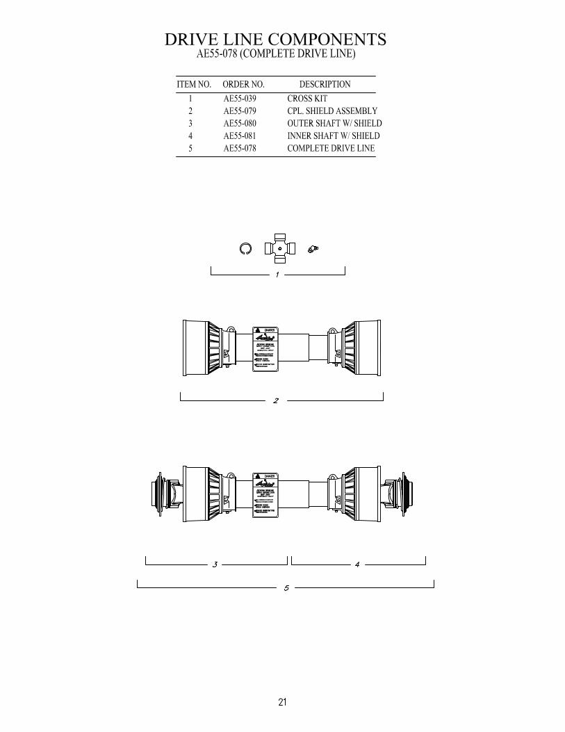
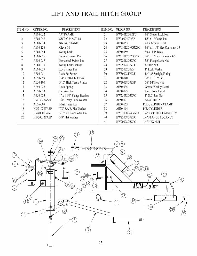
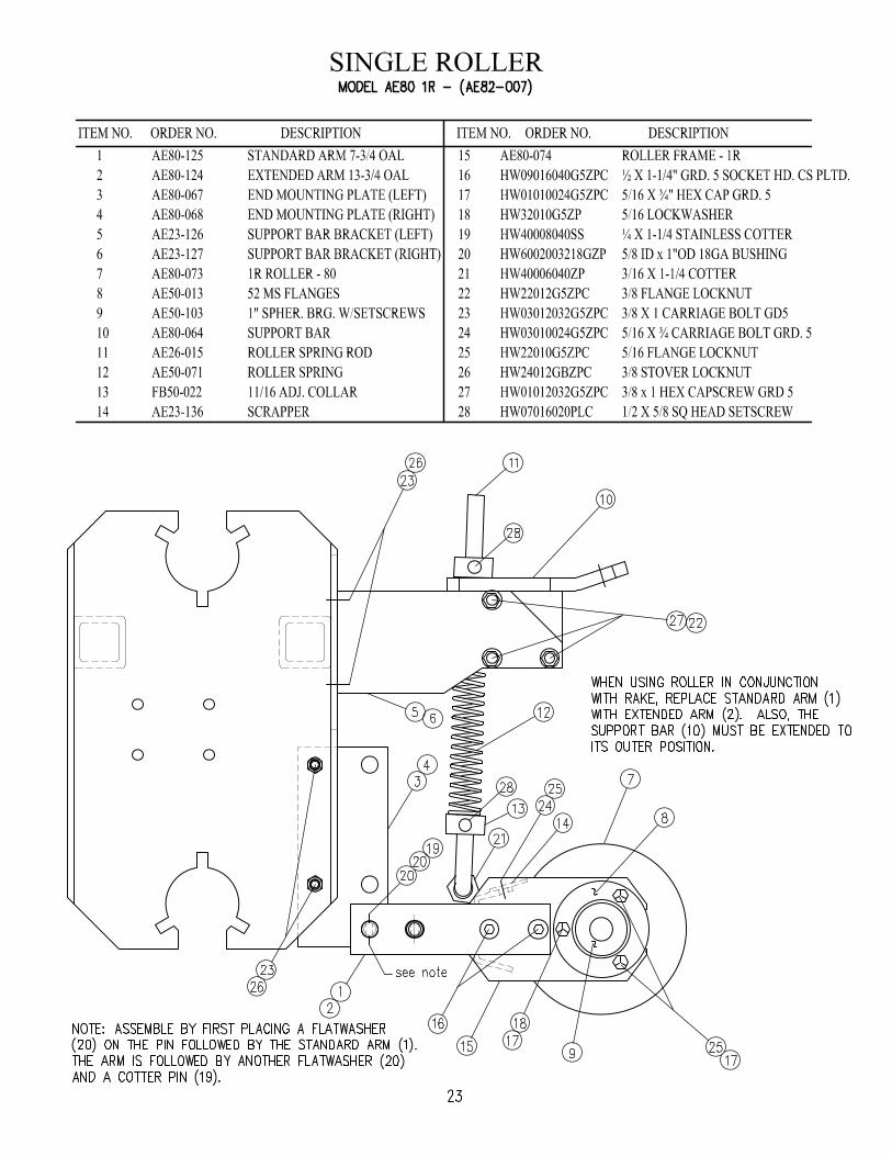
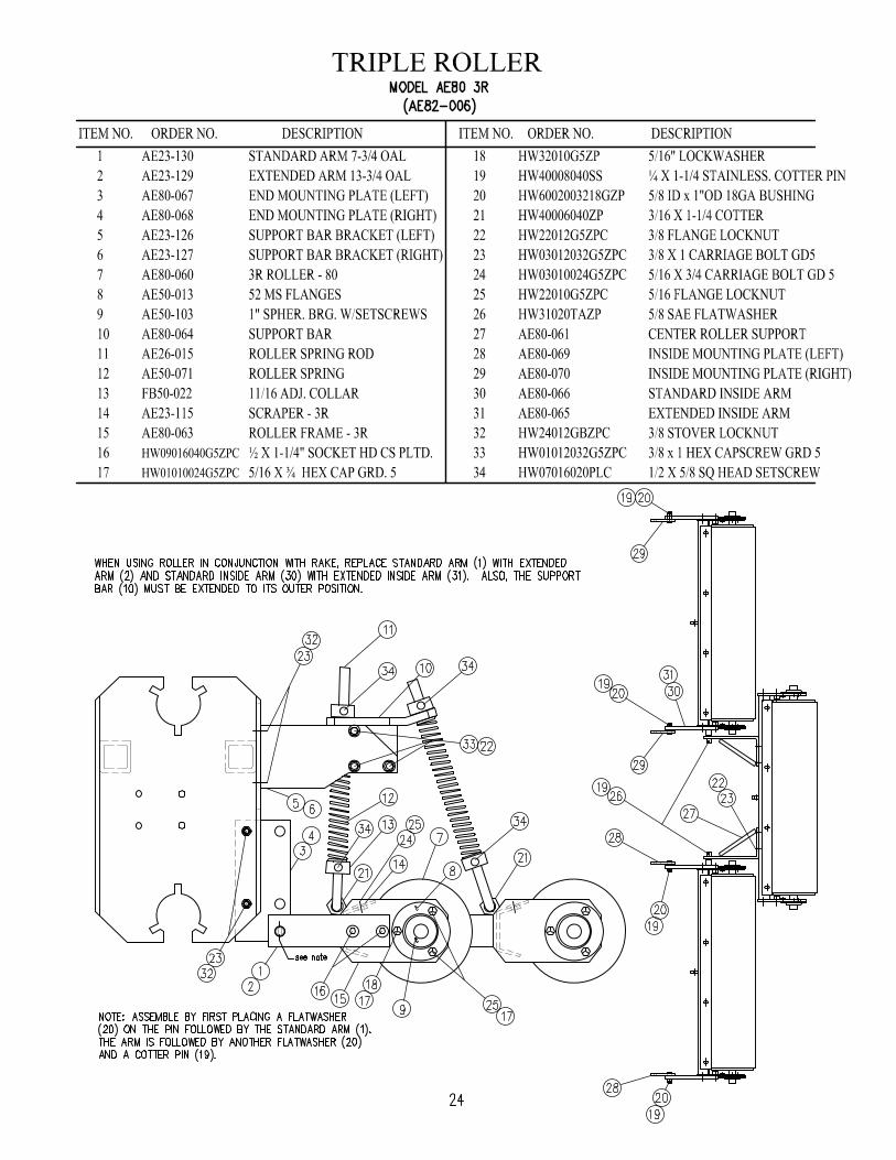
WARRANTY INFORMATION...................................................................................................................16 MAIN FRAME ASSEMBLY PARTS LIST ................................................................................................17 MAIN FRAME ASSEMBLY .......................................................................................................................18 DRIVE TRAIN COMPONENTS .................................................................................................................19 ROTOR ASSEMBLY ...................................................................................................................................20 DRIVE LINE COMPONENTS.....................................................................................................................21 LIFT AND TRAIL HITCH GROUP ............................................................................................................22 SINGLE ROLLER ........................................................................................................................................23 TRIPLE ROLLER.........................................................................................................................................24 RAKE............................................................................................................................................................25 MODEL 400-7FP SEEDER..........................................................................................................................26 BRUSH ASSEMBLY ...................................................................................................................................27 SEED HOPPER PARTS LIST......................................................................................................................28 SEEDER HOPPER........................................................................................................................................29 AE80 AERA-vator Specifications:................................................................................................................30
2

SAFETY SYMBOLS
This is a standard safety alert symbol meaning ATTENTION ! BECOME ALERT ! YOUR SAFETY IS INVOLVED !
CAUTION Indicates hazardous situation, injury may occur, used to alert against carelessness.
WARNING Indicates potentially hazardous situation. Death or serious injury may occur if proper procedures are not followed.
DANGER Indicates most hazardous situation. Death or serious injury will occur if proper pro-cedures are not followed.
3

OPERATION SAFETY
• Your Safety Is Always First! Familiarize yourself with the safety symbols and de-cals on pages 3 and 4.
• All operators should read and understand the following sections of this manual
prior to adjusting, maintaining, hitching to, or operating the AERA-vator: OPERATION SAFETY, OPERATOR INSTRUCTIONS, PRE-OPERATION CHECKS, MAINTENANCE CHECKS, MAINTENANCE SAFETY, OPERATOR MAINTENANCE.
• In addition, remove and read the drive line safety and maintenance manual taped to
the drive line shield. After reading the drive line manual, place it inside this manual for reference.
• For the safety and instruction of all operators, keep this manual stored on the AERA-
vator at all times. • Never attempt to adjust, maintain, or remove debris from any moving part of this ma-
chine while it is attached to a tractor or other power source with the engine running. • After operating, always disengage the power take off and switch the engine off prior
to dismounting from the tractor or other power source and approaching the unit. • Prior to starting, always inspect operating area for any hazards such as large rocks,
steep slopes, low tree branches or wires. Flag objects difficult to see such as irriga-tion heads and water meters.
• Instruct all people in the work area to stay clear of the unit. • Perform all pre-operation checks (page 8) prior to start up. • Never engage the power take off while the rotors are off the ground. Always disen-
gage the power take off before lifting the unit. High-speed rotors create a flying ob-ject hazard when they are lowered to the ground.
Figure 1. Tractor Roll Over/Thrown Object Warning
WARNING* TO PREVENT A THROWN OBJECT HAZARD, DO NOT ENGAGE PTO IN LIFTED POSITION. * TO PREVENT A ROLL OVER HAZARD, DO NOT LIFT UNIT ON HILLSIDE.
5
• Consult your tractor Operator's Manual regarding operation on slopes. Do not lift the unit while the tractor is moving (or parked) sideways on slopes above 5°. The swing hitch may allow the unit to swing to the downhill side and cause the tractor to roll over. On slopes from 5° to 15° always aim the tractor uphill before lifting the unit. We do not recommend the unit being used on slopes above 15°.
• Use extreme care and maintain moderate ground speed when transporting or operat-
ing on slopes, over rough surfaces, or close to trees ditches and fences. • Only operate during daylight hours or with good artificial light. • The AERA-vator is not equipped for highway use. Be careful of traffic when operat-
ing near or crossing roadways.
OPERATOR INSTRUCTIONS
• The AE-80 AERA-vator is designed to attach to a tractor with a category one three point hitch, 540 PTO, and a minimum of 35 horsepower. However, additional at-tachments (roller, seeder, etc.) may require a larger tractor for increased lifting capac-ity. Check the tractor owner and operator’s manual for lift capacity. The weight of the AE-80 and its attachments are listed in Specifications, page 31.
• Before hitching to the AERA-vator familiarize yourself with all of the tractors control
functions. Be prepared to stop the tractor movement, PTO operation, and the engine quickly in an emergency.
6
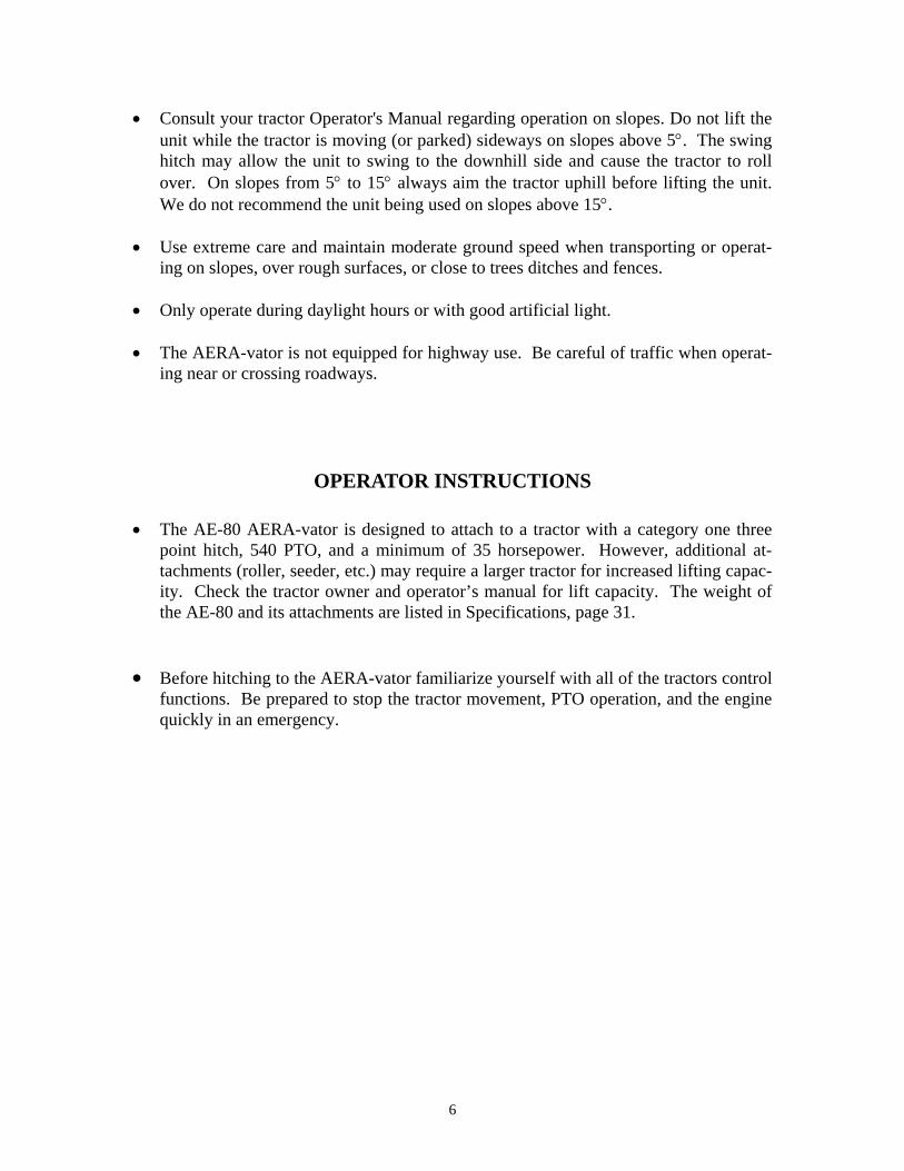
UNDERSTANDING HOW THE SWING HITCH OPERATES (PRIOR TO HITCHING TO TRACTOR)
With the swing stand lowered and the swing mast rearward to disengage the swing lock, grasp the hitch pins and rotate the “A” frame to simulate opera-tion in a sharp turn. Release the hitch pins and slowly pull the swing mast forward as it would be pulled by the top link during lifting. Notice how one mast chain tightens causing the “A” frame and unit to realign and the spring on the lock link is compressed to make the swing lock engage upon align-ment. Now push the swing mast rearward against the lock link tab to disengage the swing lock and loosen the chains to allow sharp turns again. This demonstrates how the top link of the tractor lift system switches the AERA-vator between the trail and lift modes.
Figure 2. Swing Hitch Operation
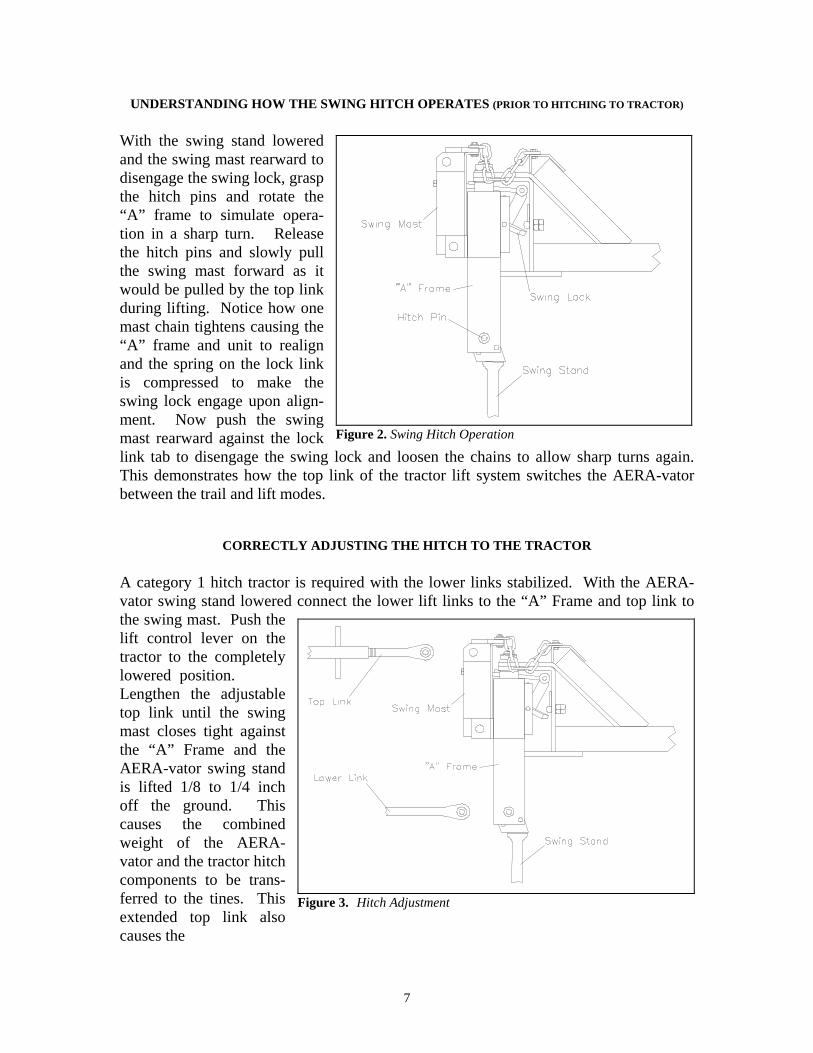
CORRECTLY ADJUSTING THE HITCH TO THE TRACTOR
A category 1 hitch tractor is required with the lower links stabilized. With the AERA-vator swing stand lowered connect the lower lift links to the “A” Frame and top link to the swing mast. Push the lift control lever on the tractor to the completely lowered position. Lengthen the adjustable top link until the swing mast closes tight against the “A” Frame and the AERA-vator swing stand is lifted 1/8 to 1/4 inch off the ground. This causes the combined weight of the AERA-vator and the tractor hitch components to be trans-ferred to the tines. This extended top link also causes the
Figure 3. Hitch Adjustment
7

AERA-vator to tilt backwards when lifting allowing gravity to assist the swing chains in aligning the unit with the tractor. DO NOT ADD ADDITIONAL WEIGHT TO THE AERA-vator OR APPLY DOWN PRESSURE TO THE TRACTOR LIFT LINKS DURING OPERATION. • The geometry of tractor lift linkages varies, and a trial run over uneven ground is rec-
ommended. Ideally the swing lock will not engage when aerating over the crown of a hill and the tractor hitch is always free to float upward at all times. The tines should clear curbs etc., when lifted.
• When lowering for operation, lower slowly until the tines touch the ground. Then
swiftly push the lift control lever on the tractor to the completely lowered position to instantly unlock the hitch. This is especially true when lowering the unit in a sharp turn. Failure to do this may cause the swing hitch not to disengage, resulting in dam-age to the machine and/or turf damage. In the event the unit should fail to unlock for trail mode, stop the tractor and repeat the lowering procedure.
DO NOT TURN THE TRACTOR WITH THE AERA-vator IN THE GROUND AND THE SWING LOCK ENGAGED. DAMAGE TO EQUIPMENT MAY OCCUR! • When operating diagonally downhill or transversely (sideways) on a hillside slope
above 5° the mast chains will not swing the unit uphill to center and lock on the trac-tor when the unit is lifted. Occasionally the unit will swing farther to the downhill side of the tractor creating the hazard of tractor roll over. If the tractor ever seems unstable, immediately lower the hitch and steer the tractor uphill or on a more level surface where it will center and lock when lifted.
• Do not back the unit up with the AERA-vator touching the ground. Always disen-
gage the PTO, raise the unit, back to desired location and then lower the machine and engage the PTO.
• The operating ground speed of the tractor will depend on the amount of soil agitation
required. Slower tractor ground speed (lower gears) will be used for renovating in extremely hard dry ground. Faster tractor ground speeds (higher gears) will be used for aeration work in normal conditions. To reduce the amount of soil agitation simply reduce the engine RPM. Three to four miles per hour is the most common speed range.
PRE-OPERATION CHECK LIST (With the AERA-vator lowered and the tractor engine switched off...)
• Be sure that the implement is hitched to the tractor properly with all pins in place. • Pin the swing stand in the up position.
8

• Be sure the driveline is correctly assembled. (The end stenciled as the tractor end is connected to the tractor and not to the AERA-vator). Check to see that the end yokes are locked to the tractor PTO and gearbox shafts. Drive shields must turn freely on the driveline.
• See that all shields are correctly installed. • Remove any debris caught in the rotors. • Check gearbox oil level before first operation and every 200 hours of operation there-
after. (Refer to operator maintenance section.)
MAINTENANCE SAFETY
• Never attempt to clean, adjust, lubricate or perform any maintenance on the AERA-vator while it is attached to the tractor or any other power source with the engine run-ning.
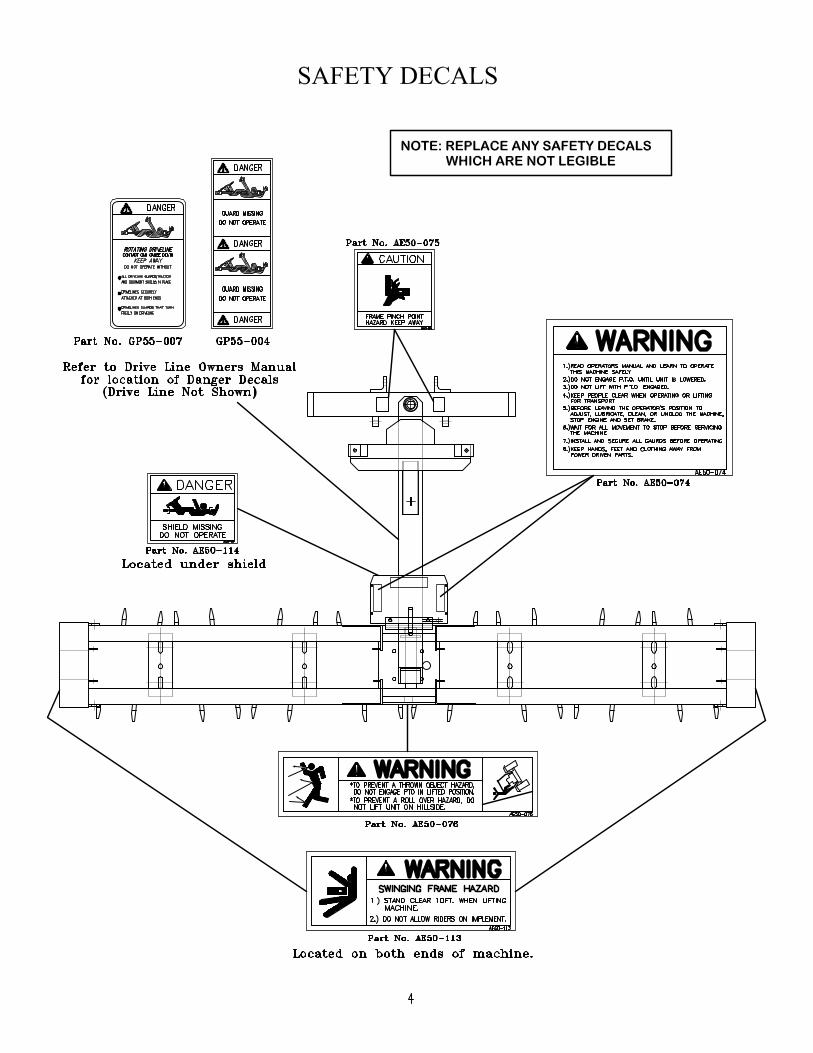
• Read and understand all safety decals prior to performing any maintenance.
Replace any safety decals which are not legible. • Never attempt to clean, adjust, lubricate or perform any maintenance on the AERA-
vator while it is attached to the tractor in the raised position unless safety blocks are inserted under the frame.
• When not attached to the tractor,
always use the lifting hook to hoist the machine for mainte-nance. (See Figure 4). Use ex-treme caution when using lifting hook because center of gravity is affected by additional attach-ments and the unit may shift rearward. Do NOT hoist the machine with the seeder at-tached.
• When installing tines, performing
any rotor shaft service, or remov-ing debris from the rotors, ensure that the rotor shaft does not rotate because a serious pinch injury could occur.
Figure 4. Swing Stand/Lifting Hook
9

OPERATOR MAINTENANCE • Check gearbox oil level before first operation and every 200 hours of operation there-
after. With frame level, remove oil level plug on front left side of gear box using 5/16” x 6” allen wrench through slots in the frame post. If required, add 90w-gear oil through plug in top of box until it appears at oil level plug. Replace both plugs se-curely.
• Grease driveline parts after the number hours use as shown in the following chart.
Figure 5 Drive Line Lube Chart
• The hitch flex joints at the top of the “A” frame and above the gearbox (see page 18) should be lubricated before first operation and weekly thereafter.
• After the first two hours of operation tighten all tines to 210-ft. lbs. Check for loose
tines daily. • When replacing lost or worn tines use a 15/16” extra deep socket (Socket is available
through our repair parts. Order # AE60T003) and torque to 210 ft. lbs. • CHECK BELT TENSION every 4 hrs. of operation for the first 12 hrs. and every
100 hrs. thereafter. Also, tighten belts if shaft hesitation is noticed during operation. Over tightening belts may cause damage to the machine. Be sure to re-install belt shield after servicing.
• Use the applicable parts break down illustration pp.17-30 for maintenance removal,
and assembly instructions. • The AERA-vator shaft and rotor bearings are sealed and permanently lubricated re-
quiring no routine maintenance.
CAUTION BE SURE ALL SAFETY SHIELDS ARE INSTALLED PRIOR TO RETURNING THIS MACHINE TO SERVICE.
10

AE-80 ROTOR SHAFT SERVICE INSTRUCTIONS (Clean the machine thoroughly with a pressure washer)
Rotor Shaft Removal (This will require a tractor with 3-point lift or overhead hoist. For safety reasons, only lift the Aera-vator approximately two inches above the work surface, never place hands or feet between the machine and the work surface).
The AE80 consists of two complete shaft assemblies and each shaft assembly can be removed separately. The following instructions are directed toward the removal of a single shaft. However, both shafts can be removed at the same time by completing each step of the procedure on each shaft before proceeding to the next. Alternatively, one shaft can be removed and then the other. 1. Remove belt cover, skid shoe and drive belts. 2. Remove 1/2” carriage bolts holding center-bearing support to main frame. 3. Remove 3/8" carriage bolts holding end rotor shaft bearing, drive end. (See Figure 6) 4. Move frame slightly to right and lift off of rotor shaft assembly.
Rotor Shaft Disassembly 1. Remove the 1-1/8" hex jam nut from the shaft end nearest to the damaged component. 2. Only remove the rotors and spacers required to reach the damaged component. Wipe the
shaft clean before each rotor is removed. Each rotor bearing has two separate cones with a hex bore adapter pressed in each. Each cone is held in position by an internal grease seal, which allows the cones to be moved apart slightly. When they are moved apart any dirt allowed inside the hex adapters can fall between the cones and contaminate the bearing. If the cones are forced apart the internal seals become ruined and irreplaceable.
A B B C C C C B B A
Figure 6. Rotor Shaft Assembly
11

2. Clean and inspect parts as they are removed and set aside in their order of removal to simplify
re-assembly.
Figure 7. Rotor Shaft Disassembly
Rotor Hub Disassembly 1. With a pry bar remove the external seals (Figure 8) on both sides. Generally, seals are damaged and are not reused.
STEP 3
EXTERNAL SEAL - STEP 1SNAP RING - STEP 2
PRESS RAM
PRESS TOOLAE60T007
TOOL CAPAE60T008
PRESSTABLE
Figure 8. Rotor Hub Disassembly
2. Remove the snap rings on both sides. 3. Press used bearing and adapter assembly out.
12
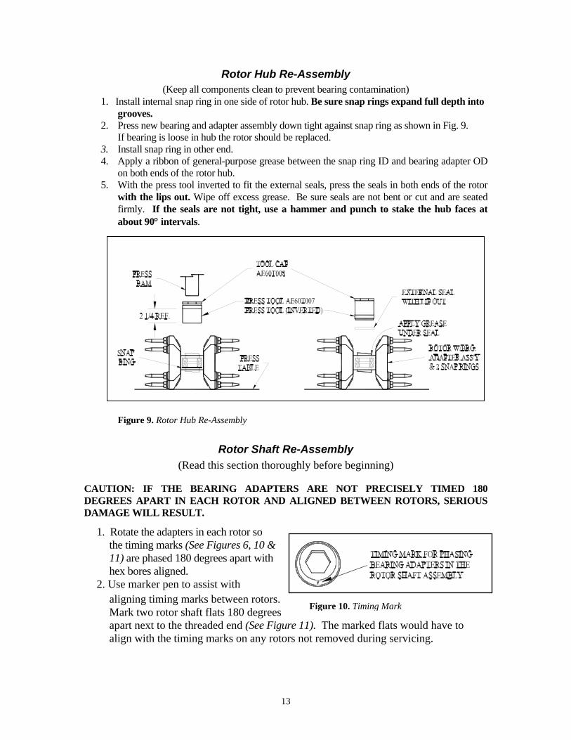
Rotor Hub Re-Assembly (Keep all components clean to prevent bearing contamination)
1. Install internal snap ring in one side of rotor hub. Be sure snap rings expand full depth into grooves.
2. Press new bearing and adapter assembly down tight against snap ring as shown in Fig. 9. If bearing is loose in hub the rotor should be replaced. 3. Install snap ring in other end. 4. Apply a ribbon of general-purpose grease between the snap ring ID and bearing adapter OD
on both ends of the rotor hub. 5. With the press tool inverted to fit the external seals, press the seals in both ends of the rotor
with the lips out. Wipe off excess grease. Be sure seals are not bent or cut and are seated firmly. If the seals are not tight, use a hammer and punch to stake the hub faces at about 90° intervals.
Figure 9. Rotor Hub Re-Assembly
Rotor Shaft Re-Assembly (Read this section thoroughly before beginning)
CAUTION: IF THE BEARING ADAPTERS ARE NOT PRECISELY TIMED 180 DEGREES APART IN EACH ROTOR AND ALIGNED BETWEEN ROTORS, SERIOUS DAMAGE WILL RESULT.
1. Rotate the adapters in each rotor so the timing marks (See Figures 6, 10 & 11) are phased 180 degrees apart with hex bores aligned.
Figure 10. Timing Mark
2. Use marker pen to assist with aligning timing marks between rotors. Mark two rotor shaft flats 180 degrees apart next to the threaded end (See Figure 11). The marked flats would have to align with the timing marks on any rotors not removed during servicing.
13

SPACER
TIMING MARKON BRG. ADAPTER
REVOLVED VIEW OFBRG. ADAPTER FACE
MARK SHAFT FLATS180° APART
Figure 11.
3. Install the required components in the sequence shown in Figure 11, double checking the timing mark locations and spacer lengths (see following table) as each rotor is installed.
SPACER LENGTH PART NO.
A 3 51/64” AE24-027 B 7 1/4” AE24-011 C 3 9/16” AE24-028
CAUTION: CLEAN THE ROTOR SHAFT THOROUGHLY REMOVING ANY BURRS THAT WOULD KEEP THE ROTOR ASSEMBLIES FROM SLIDING ON FREELY. IF A BEARING ADAPTER JAMS, THE INTERNAL BEARING SEAL COULD BE FORCED OUT AND IT IS NOT REPLACEABLE. NOTE: THE SPACERS MUST BE FULLY SEATED IN EACH ADAPTER COUNTERBORE BEFORE TIGHTENING. DO NOT FORGET TO PLACE THE BEARING STAMPINGS ON EACH OF THE SHAFT BEARINGS DURING REASSEMBLY. ALSO, THE 3/8" CARRIAGE BOLTS SHOULD BE PLACED IN THE BEARING STAMPINGS ON THE DRIVE END OF THE SHAFT BEFORE THE PULLEY IS REPLACED. 4. Replace the 1-1/8" hex jam nut and rotate each rotor occasionally as the nut is torqued to 350 ft-lbs. If any rotor locks up, the bearing adapters in the rotor are probably not phased 180 degrees apart or the spacers are not fully seated.
14

Rotor Shaft Installation 1. Roll Rotor Shaft Assembly into position under frame bearing holes with pulley on drive end. 2. Carefully lower unit in small increments while keeping both bearing flanges on the side of the
frame end plate and center bearing support. 3. Note that as the frame ends and center bearing support are carefully lowered down beside
each pair of bearing flanges it is necessary to push the unit away from the pulley end. This al-lows the frame end to pass the carriage bolts sticking through both bearing flanges next to the pulley.
4. When the frame ends align with the carriage bolt holes and the bearing flanges, pull the unit toward the pulley end to assemble nuts on carriage bolts.
5. Install bolts and nuts in center bearing support and other end plate being careful to align car-
riage bolt shoulders with the square holes in bearing flanges (hand tighten). 6. Tighten all bearing flange bolts 30-35 Ft-Lbs. 7. Tighten 3 bolts connecting center bearing support to frame 50-55 Ft. Lbs. 8. Install and tighten drive belts. Tighten both bolts in belt idler bracket 30-35 Ft. Lbs. 9. Install Skid Shoe and tighten bolts 15-20 Ft. Lbs. 10. Install Belt Cover and tighten bolts 8-12 Ft. Lbs. 11. Run the machine and check for loose or improperly installed components.
Tine Replacement Assemble tines to rotor as shown below (Fig 12). Torque tines to 210 ft-lbs.
TO 210 FT-LBS.NOTE: TORQUE TINES
5/8 LOCK WASHER
HW20020G5ZPC5/8 NF HEX NUT
GRADE 8
AE50-058 (TINE)
HW32020G8ZP
AE50-058 (TINE)
Figure 12. Tine Replacement
15
WARRANTY INFORMATION
ONE YEAR LIMITED WARRANTY
FIRST PRODUCTS INC. WARRANTS THIS PRODUCT TO BE FREE OF DEFECTS IN MATERIALS AND WORKMANSHIP FOR A PERIOD OF TWELVE MONTHS FROM THE ORIGINAL DELIVERY DATE. THIS WARRANTY DOES NOT COVER PARTS CAUSED TO BE DEFICIENT DUE TO NORMAL WEAR, MISUSE, ACCIDENTS, OR LACK OF PROPER
AINTENANCE. M ANY PARTS THOUGHT TO BE DEFECTIVE MUST BE RETURNED TO THE DEALER/DISTRIBUTOR FOR WARRANTY CONSIDERATION JOINTLY WITH FACTORY REPRESENTATIVES. A RETURN AUTHORIZATION NUMBER MUST BE OBTAINED AND CLEARLY MARKED ON ALL PACKAGES OF PARTS REQUIRING RETURN TO THE FACTORY. THE OBLIGATION OF FIRST PRODUCTS INC. UNDER THIS WARRANTY SHALL BE EXCLUSIVELY LIMITED TO REPLACEMENT OF PARTS DETERMINED TO BE DEFECTIVE BY FIRST PRODUCTS INC. WITH FREIGHT PREPAID. IN NO EVENT SHALL FIRST PRODUCTS INC. BE LIABLE FOR INDIRECT, INCIDENTAL, OR CONSEQUENTIAL DAMAGES IN CONNECTION WITH THE USE OF THIS PRODUCT. FIRST PRODUCTS INC. RESERVES THE RIGHT TO MAKE CHANGES OR ADD IMPROVEMENTS TO ITS PRODUCTS AT ANY TIME WITHOUT OBLIGATION TO MAKE SUCH CHANGES OR IMPROVEMENTS ON PRODUCTS SOLD PREVIOUSLY.
16


AE80 AERA-vator Specifications: WEIGHT (Basic Unit) 932 LBS. w/DRIVE SHAFT
Standard Mount 1R Roller - 6-5/8”dia. w/SCRAPER 259 LBS.
Extended Mount 1R Roller - 6-5/8”dia. w/SCRAPER 263 LBS.
Standard Mount 3R Roller - 6-5/8”dia. w/SCRAPER 315 LBS.
Extended Mount 3R Roller - 6-5/8”dia. w/SCRAPER 326 LBS.
Rake - 1 7/8” TINE SPACING APPROX 53 LBS.
Brush – 76” Wide, Polypropylene Bristle 56 LBS. (1R ROLLER only)
Seeder (84” Wide) Empty 298 LBS.
OVERALL WIDTH 88”
WORKING WIDTH 80”
GEARBOX 1:1 RT. ANGLE
END DRIVE 2 BX BELTS
TINE VIBRATION FREQUENCY @540 PTO RPM = 800 CYCLES/MIN.
SIDE TO SIDE TINE TRAVEL 1 3/8 INCHES
VIBRATING DEPTH 3 1/2 INCHES
AERATION DENSITY 6 HOLES/SQ. FT
HEAVY DUTY LIFT/TRAIL HITCH 3 FT TURN RADIUS (APPROX.)
TINES 9/16 x 3 1/2” FORGED AND HARDENED
ROTOR BEARINGS DOUBLE SEALED TAPERED ROLLER
DRIVE LINE 1 3/8 SPLINE w/SAFETY SHIELD
FINISH - BASIC UNIT BLACK AND GREY ACRYLIC
SEEDER HOPPER
RED POLYESTER
HOPPER CAPACITY 9.4 Cubic Ft.
HOPPER BOTTOM & SLIDE STAINLESS STEEL (MICRO-PRECISION MATED)
SEED FEED ROTOR PRECISION NEOPRENE
SEED DISTRIBUTION 30 OUTLETS WITH SPLASH PLATE
RATE CONTROL PRECISION CAM GAUGE
SEEDER DRIVE ELECTRIC DRIVE – (CONNECTS TO TRACTOR BATTERY)
TRACTOR REQUIRED: HP AND PTO SPEED
3 PT. LIFT HITCH
35 HP – 540 RPM CAT 1
SPECIFICATIONS SUBJECT TO CHANGE WITHOUT NOTICE
30