operator's manual - manac
TRANSCRIPT

Operator’smanual
CautionThis manual
contains importantsafety information.
Read manualcarefully.
Keep manualwith Manac’s
semitrailerat all times.
Manac semitrailer
303
8051
10/
2011
www.manac.us

Operator’s instructions
This manual has been prepared to assist you in retaining the safety, dependability, and performancethat are built into Manac trailers. It is essential that thissemitrailer receives periodic inspections, maintenance,and service parts replacement. This manual includessafety checks that the operator should perform periodically. It is important that every semitrailer ownerand/or operator have an organized SemitrailerPreventive Maintenance (TPM) program. United Statesand Canada Departments of Transportation require bylaw that the maintenance records be kept on every commercial highway vehicle. It is to your advantage tobe able to show that regularly scheduled TPM
inspection checks have been made on every piece of equipment operated.
Not only will a regular TPM program assure you thatyou will get the most from your Manac semitrailer, butalso you may place yourself in a favorable legal positionin the event of an accident involving this equipment.
Read this manual carefully. Should you have any questions, contact a Manac Semitrailer factory representative immediately for the answers. This manualshould be kept with the semitrailer and should remainwith the semitrailer when it is sold.
Operator’s instructions Operator’s instructions
3

Operator’s instructions 3
Coupling 5
Uncoupling 10
Normal use 12
Certification plate 13
Pre-trip check list 14
Electrical system 16
Typical wiring diagram 17
Slider running gear 18
Care and adjustment of brakes 19
Air system and brake operation 19
Tires 20
Tire loads 20
Proper use of steps and hand-holds 21
Rims and wheels 22
Spindle axle nut instructions 26
Wheels 28
Leaf-spring suspension 30-31
Air suspension 32
Suspension safety and inspection 33
Exhaust (dump) valve operation 34-35
Reporting safety defects 36
• • • • • • • • • • • • • • • • • •
• • • • • • • • • • • • • • • • • • • • • • • •
• • • • • • • • • • • • • • • • • • • • • • •
• • • • • • • • • • • • • • • • • • • • • •
• • • • • • • • • • • • • • • • • • • •
• • • • • • • • • • • • • • • • • • • •
• • • • • • • • • • • • • • • • • • • •
• • • • • • • • • • • • • • • • • •
• • • • • • • • • • • • • • • • • • •
• • • • • • • • • • • • • • •
• • • • • • • • • • • • • • •
• • • • • • • • • • • • • • • •
• • • • • • • • • • • • • • • • • • • • • • • •
• • • • • • • • • • • • • • • •
• • • • • • • • • • • • • • • • • • • • •
• • • • • • • • • • • • • • • • • • • • • • •
• • • • • • • • • • • • •
• • • • • • • • • • • • • • • • • • • •
• • • • • • • • • • • • •
• • • • • • • • • • • • •
• • • • • • • • • • • • • • • • •
Table of contents
4
� • • • • • • • • • • • • • • • • • • • • • • • •
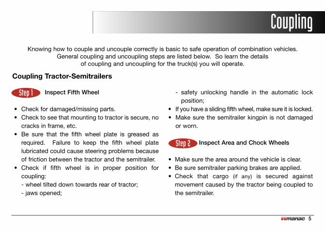
Knowing how to couple and uncouple correctly is basic to safe operation of combination vehicles. General coupling and uncoupling steps are listed below. So learn the details
of coupling and uncoupling for the truck(s) you will operate.
Coupling Tractor-Semitrailers
Inspect Fifth Wheel
• Check for damaged/missing parts.• Check to see that mounting to tractor is secure, no
cracks in frame, etc.• Be sure that the fifth wheel plate is greased as
required. Failure to keep the fifth wheel plate lubricated could cause steering problems because of friction between the tractor and the semitrailer.
• Check if fifth wheel is in proper position for coupling:- wheel tilted down towards rear of tractor;- jaws opened;
- safety unlocking handle in the automatic lock position;
• If you have a sliding fifth wheel, make sure it is locked.• Make sure the semitrailer kingpin is not damaged
or worn.
Inspect Area and Chock Wheels
• Make sure the area around the vehicle is clear.• Be sure semitrailer parking brakes are applied.• Check that cargo (if any) is secured against
movement caused by the tractor being coupled to the semitrailer.
Step 1
Step 2
Coupling
5

Position Tractor
• Back the tractor directly in front of the semitrailer. (Never
back under the semitrailer at an angle, because you might
push the semitrailer sideways and damage the support legs.)
• Check position, using outside mirrors, by looking down both sides of the semitrailer.
Back Slowly
• Back until fifth wheel just touches the semitrailer.• Do not hit the semitrailer.
Secure Tractor
• Put on the parking brake.• Put transmission in neutral.
Check Semitrailer Coupler Height
• The semitrailer should be low enough so that it israised slightly by the tractor when the tractor is backedunder it. Raise or lower the semitrailer as needed. (Ifsemitrailer is too low, tractor may strike and damage nose of the
semitrailer; if semitrailer is too high, it may not couple correctly.)
• Check that the kingpin and fifth wheel are aligned.
Step 3
Step 4
Step 5
Step 6
6
Coupling Height CautionIt is important to verify before coupling your
Manac semitrailer if fifth wheel coupling heightis compatible with the semitrailer coupling
height. Too high or too low fifth wheel coupling height may result in premature
wearness, tires, brakes, bearings etc. Also toohigh coupling height may result to an overall
dimension higher than 13’6”.
SAMPLE
CAUTION13’6” HIGHMAXIMUMFIFTH WHEEL
HEIGHT47”

Connect Air Lines to Semitrailer
• Check glad hand seals and connect tractor supply(emergency) air line to semitrailer supply (emergency)
glad hand.• Check glad hand seals and connect tractor control
(service) air line to semitrailer control (service) glad hand.• Make sure air lines are safely supported where
they will not be crushed or caught while tractor is backing under the semitrailer.
Supply Air to Semitrailer
• From the cab, push in “Air Supply” knob or move tractor protection control valve from the “Emergency” to the “Normal” position to supply air to the semitrailer brake system.
• Wait until the air pressure is normal.• Check brake system for crossed air lines:
- shut engine off so you can hear leaks in the brake system;
- apply and release semitrailer brakes. Listen forsound of semitrailer brakes being applied andreleased. You should hear the brakes move whenapplied and air escape when the brakes are released;
- check air brake system pressure gauge for signsof major air loss;
• When you are sure semitrailer brakes are working,start engine.
• Make sure air pressure is up to normal.
Lock Semitrailer Brakes
• Pull out the “Air Supply” knob or move the tractor protection control valve from “Normal” to “Emergency”.
Back Under Semitrailer
• Use lowest reverse gear.• Back tractor slowly under semitrailer to avoid
hitting the kingpin too hard.• Stop when the kingpin is locked into the fifth wheel.
Step 10
Step 8
Step 7
Step 9
7

Check Connection for Security
• Raise semitrailer support legs slightly off ground.• Pull tractor gently forward while the semitrailer
brakes are still applied.
Secure Vehicle
• Put transmission in neutral.• Put parking brakes on.• Shut off engine and take the key with you so
someone else will not move the tractor-semitrailerwhile you are under it.
Inspect Coupling
• Use a flashlight if necessary.• Make sure there is no space between upper coupler
and fifth wheel. If there is space, something is wrong(kingpin may be on top of closed fifth wheel jaws; semi-
trailer could come loose very easily).
• Go under semitrailer and look into the back of thefifth wheel. Make sure the fifth wheel jaws haveclosed around the shank of the kingpin.
• Check that the locking lever is in “lock” position.• Check that the safety catch is in position over
locking lever. (On some fifth wheels, the catch must be
put in place by hand.)
• If the coupling is not right, do not drive the coupledunit; get it fixed.
Connect the Electrical Cord and Check Air lines
• Plug the electrical cord into the semitrailer and fasten the safety catch.
• Check both air lines and electrical line for signs ofdamage. Repair or replace if necessary.
• Make sure air and electrical lines will not hit anymoving parts of vehicle.
Step 11
Step 14Step 12
Step 13
8

Raise Semitrailer Support Legs (Landing Gear)
• Use low-gear range (if so equipped) to begin raising the support legs. Once free of weight, switch to the high-gear range.
• Raise the support legs all the way up. (Never drive
with support legs only part way up as they may catch on
railroad tracks or other things.)
• After raising the support legs, properly secure thecrank handle.
• With the front of the semitrailer supported by thetractor:- check for enough clearance between rear of
tractor frame and support legs. (When tractor turns
sharply, it must not hit the support legs or their bracing);
- check that there is adequate clearance betweenthe top of the tractor tires and the underside of the semitrailer.
Step 15
9
Connector wiring changeNotice for all tractor-semitrailer owners and users
Federal Motor Vehicle Safety Standard No. 121, Air BrakeSystems, was amended by the National Highway TrafficSafety Administration of DOT requiring that truck tractorsmanufactured on/or after March 1, 1997, provide constantpower for a semitrailer’s antilock brake system (ABS).Some manufacturers will provide this feature prior to theeffective date. These tractors using a single 7-way electricalconnector will have constant power for ABS on the centerpin when the key switch is on. Tractor-semitrailer ownersand users who presently use the center pin for auxiliarypower for equipment other than semitrailer ABS (for example:dome lights, backing lights, bottom dumps, sliding undercarriages,air ride dump valves, etc.) will be affected by this change. Incertain uses of this constantly powered center pin connector, unexpected or unintended activation of thisequipment may be hazardous or result in personal injury.Before connecting your semitrailer to a tractor, make surethat the constantly powered center pin will not unintentionallyturn on semitrailer equipment. If you have any questionsabout your present wiring, or how to rewire your vehicles,you should contact the tractor supplier and/or MANACCustomer Service Department.
C a u t i o n

Step 3
Step 4
Uncoupling Tractor-SemitrailersThe following steps willl help you to uncouple safely.
Position Rig
• Make sure surface of parking area can support weight of semitrailer.
• Place tractor in a straight line with the semitrailer.(Pulling out at an angle can damage the support legs.)
Ease Pressure on Locking Jaws
• Shut off semitrailer air supply to lock semitrailer brakes.• Ease pressure on fifth wheel locking jaws by
backing up gently (this will help you release the fifth wheel
locking lever).• Put parking brakes on while tractor is pushing
against the kingpin. This will hold rig with pressureoff the locking jaws.
Lower The Support Legs
• Lower the support legs until they make firm contact withthe ground. Turn crank in low gear a few extra turns. This will lift some weight off the tractor. (Do not lift semitrailer off the fifth wheel.) This will:- make it easier to unlatch fifth wheel;- make it easier to couple next time.
Disconnect Air Lines and Electrical Cable
• Disconnect air lines from semitrailer. Connect airline glad hands to dummy couplers at back of cab,or couple them together.
• Hang electrical cable with plug down to prevent moisture from entering it.
• Make sure lines are supported so they will not be damaged while driving the tractor.
Step 1
Step 2
10
Uncoupling

Unlock Fifth Wheel
• Raise release handle lock.• Pull the release handle to “open” position.• Keep legs and feet clear of the rear tractor wheels
to avoid serious injury in case the vehicle moves.
Pull Tractor Partially Clear of Semitrailer
• Pull tractor forward until fifth wheel comes out from under the semitrailer.
• Stop with tractor frame under semitrailer (prevents
semitrailer from falling to ground, if support legs should
collapse or sink).
Secure Tractor
• Apply parking brakes.• Place transmission in neutral.
Inspect Semitrailer Support
• Make sure ground is supporting semitrailer.• Make sure support legs are not damaged.
Pull Tractor Clear of Semitrailer
• Release parking brakes.• Check and drive tractor clear.
Step 5
Step 6
Step 8
Step 9
Step 7
11

1. this semitrailer was built to carry cargo within the limitations of weight ratings shown on the certifica-tion/identification plate. These ratings, GAWR andGVWR are:
a. the GAWR (gross axle weight rating) is the structural capability of the lowest rated member of the running gear components: suspension and spring system, hub, wheels and drums, rims, bearings, brakes, axles or tires.
b. the GVWR (gross vehicle weight rating) is the structural capability of the semitrailerwhen supported by the kingpin and axleswith the load uniformly distributed throughoutthe cargo space.
c. this semitrailer will carry a total payload ofthe Gross Vehicle Weight Rating (GVWR) less the weight of the semitrailer.
2. the cargo should be properly loaded, blocked, andbraced to prevent load shifts and to comply withthe existing regulations of the North AmericanCargo Securement Harmonisation.
CautionThe maximum load indicated
on the certification/identification plate may or may not be a legal load on the highway
you plan to use.
Normal useThis Manac semitrailer was designed for operation within legal highway speed limits on reasonable road
surfaces for the type of service it was built to perform in accordance with the following:
12

13
SAMPLE
MANUFACTURED BY:FABRIQUÉ PAR:
MANAC TRAILERS USA INC.MANAC TRAILERS USA INC.
AU/IN USA
DATE: 08/2011
GVWRPNBV
V.I.N.
SINGLESIMPLE
LB77000 KG34927 MODEL SGH42
TYPE TRA/REMTRA/REM
AXLESESSIEUX
FRONT 21000 9525 11R24 5 (G) 24.5X8.25 100 689 X
21000 9525 11R24 5 (G) 24.5X8.25 100 689 XREAR
GAWRPNBE
LB KG
TIRESPNEUS
RIMSJANTES
COLD INFL. PRESSUREPRESS. GONFL. À FROID
PSI KPA
DUALJUMELÉS
5MC314226CP013847
THIS VEHICLE CONFORMS TO ALL APPLICABLE US FEDERAL MOTOR VEHICLE SAFETY STANDARDS IN EFFECT ON THE DATE OF MANUFACTURE
SHOWN ABOVE.
''THIS VEHICLE CONFORMS TO ALL APPLICABLE STANDARDS PRESCRIBED UNDER THE CANADIAN MOTOR VEHICLE SAFETY REGULATIONS IN AFFECT
ON THE DATE OF MANUFACTURE/ CE VÉHICULE EST CONFORME À TOUTES LES NORMES QUI LUI SONT APPLICABLES EN VERTU DU RÉGLEMENT
SUR LA SÉCURITÉ DES VÉHICULES AUTOMOBILES DU CANADA EN VIGUEUR À LA DATE DE SA FABRICATION''
Certification plate

INSIDE
Parking brake (apply)
START ENGINEOil pressure (light or gauge)Air pressure (gauge)Low air warning device:• air pressure below 40 psi, check on pressure build-up. • air pressure above 60 psi, deplete air until warning device works.Instrument panel (telltale lights or buzzers)
HornWindshield wiper and washerHeater-defrosterMirrorsSteering wheel (excessive play)Apply semitrailerbrakes in emergencyTurn on all lights, including 4-way flasherFire extinguisher andwarning devices.
Pre-trip check list
14
BUREAU OF MOTOR CARRIER SAFETY
WASHINGTON, D.C.
Open letter to all Truck Drivers
The brochure has been prepared as part of our continuing effort to
improve the safety of operation on the highway of commercial motor
vehicles. We fully recognize that you, as a professional truck driver,
play a key part in our mutual effort to reduce deaths, injuries, and
property damage accidents involving trucks.
In order to assist you in doing a better job, we have prepared a pre-
trip check list designed to provide a safe, sequential, and timesaving
procedure to ckeck your truck - thus helping to assure you a safe
trip. This list includes the Federal regulatory pretrip check require-
ments. However, and more importantly, it is intended to provide
you, the professional driver, with a reminder to do what you should
always do - check your equipment before each trip.
The recommended procedure can be likened to a pilot performing
his preflight check on the aircraft before takeoff. Much of the pre-
flight check is a visual inspection, and the same type procedure can
be equally effective in a truck precheck.
Remember - you, the driver, are in the best position to know your
truck - you are truly the first line of defense against unsafe vehicles.
Sincerlely yours,
Director of Motor Carrier Safety
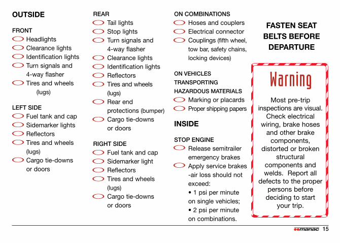
OUTSIDE
FRONTHeadlightsClearance lightsIdentification lightsTurn signals and 4-way flasherTires and wheels
(lugs)
LEFT SIDEFuel tank and capSidemarker lightsReflectorsTires and wheels (lugs)Cargo tie-downs or doors
REARTail lights Stop lightsTurn signals and 4-way flasherClearance lightsIdentification lightsReflectorsTires and wheels (lugs)Rear end protections (bumper)Cargo tie-downs or doors
RIGHT SIDEFuel tank and capSidemarker lightReflectorsTires and wheels (lugs)Cargo tie-downs or doors
ON COMBINATIONSHoses and couplersElectrical connectorCouplings (fifth wheel,tow bar, safety chains, locking devices)
ON VEHICLES
TRANSPORTING
HAZARDOUS MATERIALS
Marking or placardsProper shipping papers
INSIDE
STOP ENGINERelease semitrailer emergency brakes Apply service brakes-air loss should not exceed:• 1 psi per minute on single vehicles;• 2 psi per minute on combinations.
FASTEN SEATBELTS BEFOREDEPARTURE
WarningMost pre-trip
inspections are visual.Check electrical
wiring, brake hosesand other brake
components, distorted or broken
structural components andwelds. Report all
defects to the properpersons beforedeciding to start
your trip.
15

Electrical system
16
Caution See “Connector wiring change” page 9.
GRD RETURN TO TOWING VEH.
CLR, S.M. AND ID LAMPS
LEFT TURN SIG. + HAZARD
STOP LAMPS + ANTILOCK (ABS)
RIGHT TURN SIG. + HAZARD
TAIL + LICENCE PLATE LAMPS
ABS CONTINUOUS SHARED POWER+ STEERABLE AUTO-LIFT CONTROL
+ DOME LAMPS
WHT / BLANC
BLK / NOIR
YEL / JAUNE
RED / ROUGE
GRN / VERT
BRN / BRUN
BLU / BLEU
MISE À LA MASSE
G. GABARIT, POSITION & IDENTIFICA.
CLIGNOTANT GAUCHE + F. URGENCE
F. FREINAGE + FREINS ABS
CLIGNOTANT DROIT + F. URGENCE
F. ARRIÈRE + LAMPE PL. D’IMMATRI.
ALIMENTATION CONTINU DE L’ABS+ CONTRÔLE DE L’AUTO-VIREUR+ LAMPES DE TOIT
WHT / BLANC
BLK / NOIR
YEL / JAUNE
RED / ROUGE
GRN / VERT
BRN / BRUN
BLU / BLEU
GRD RETURN TO TOWING VEH.
DOOR LOCK + DROP VALVE
ABS MALFUNCTION SIGNAL
AIR LIFT
2nd AIR-LIFT + BLOW DOWN
BACK-UP LAMPS
NOT USE
MISE À LA MASSE
BARRURE PORTE + VALVE DE PURGE
SIGNAL D’ERREUR SYSTÈME ABS
SUSPENSION LEVANTE
2e SUSP. LEVANTE + VIDAGE D’AIR
LAMPES DE RECUL
NON UTILISÉE
The lights and wiring system on a Manac semitrailer meetor exceed all federal and state requirements in effect at the timeof manufacture. Wherever required by law, lights and reflectorsare marked by the manufacturer to indicate the appropriatespecification with which each complies.
For optimum performance and long life from the semitrailer’slights and wiring, follow this inspection procedure:
• Clean all reflectors and lights. See that all lights burnproperly. Replace all burned out lights and broken reflectors.Factory approved replacement parts should be used, andreplacement bulbs of equal candlepower should be used forsafety.
• Inspect all wiring to see that it is not frayed and that it isproperly supported and protected, with all connections tight.See that the light cable is clear and long enough to permitjack-knife parking. Be certain that the cable is supported so thatit cannot be pinched or entangled by the lower and uppercouplers. Keep the 7-way plug on the light cable and the 7-wayconnnector on the semitrailer, free of corrosion.
• Never replace fuses or breakers with metal foil or otherdevices.
Usual electrical front plug configurations used by ManacV
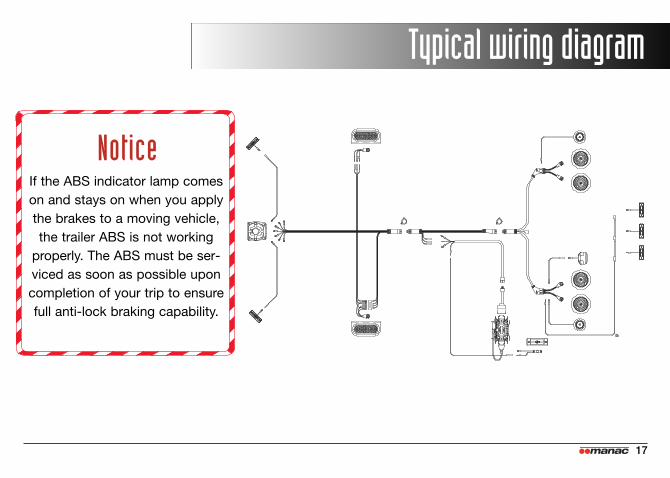
Typical wiring diagram
17
NoticeIf the ABS indicator lamp comeson and stays on when you applythe brakes to a moving vehicle,the trailer ABS is not working
properly. The ABS must be ser-viced as soon as possible upon completion of your trip to ensurefull anti-lock braking capability.

Slider running gear
18
Reposition the slider
1.Set the tractor and semitrailer brakes.2.Remove the stop bar and move to desired position.
(Picture A)3.Determine whether the slider has on air assisted or a
manual pin release system. (Picture B)4. Air assisted: disconnect the safety glad hand. Connect
the truck tractor safety glad hand to the third auxiliary glad hand. Pins will disengage. (See decal on front)
5. Manual pins: release the operating handle for mechanicalpin release. (See decal on semitrailer side)
6.Gently rock the semitrailer forward and rearward tofully retract the pins.
7. Slide the slider to the desired position by ONLY releasingthe tractor brakes and carefully moving the semitraileruntil the slider contacts the stop bar.
8.Release the operating handle.9.Visually check all locking pins for proper engagement.
Chamfered ends of the pins must project through the body rail at all four locations. (Picture C)
10.Locate the stop bar directly behind the slider system. (Picture D)
11.Check pin engagement by gently rocking the semitrailerforward and rearward.
CautionFailure to properly secure slider box to body railcan cause loss of vehicle control that can resultin death or serious injury and property damage.
A B
C D

Care and adjustment of brakes
19
The semitrailer brake systems will perform safely and efficiently only as long as you maintain them properlyand do not abuse them. Semitrailer brakes should beinspected frequently and adjusted, if needed, in connectionwith a Semitrailer Preventive Maintenance program.
Out-of-adjustment brakes can cause increased stoppingdistance, shorter brake component life, and a tendencyfor the semitrailer, and the truck tractor equipment tojack-knife.
Air system and brake operation• Inspect the glad hands for seal damage and crackedhousings. Inspect the air hoses for cracking and for frayedconnections. Replace or repair damaged components.• Keep the air system clean. Air tanks should be draineddaily to remove moisture and other contaminants,especially during cold weather operations.• Use of additives as antifreeze in the air brake system isnot recommended. They may result in deterioration ofvalve seals and effect performance of the brake system.• Keep the air system tight. The air system cannot becharged properly if there are leaks in reservoirs, lines,hoses or valves.
• Run the tractor engine until the air brake systempressure gauge shows at least 105 psi. With theengine off, listen for air leaks and check the gaugereading with no brakes applied. Remember that seriousair losses are extremely hazardous conditions thatmight cause accidents or breakdowns.
CautionDo not operate this vehicle with any brakedefects or with brakes not well adjusted.

Tires
20
Do not over inflate. Check for proper inflation with anaccurate gauge when the tires are cold. Check thespare too. Inspect tires for nails and other objectsembedded in the rubber, and for stones and otherobjects lodged between duals.
Examine tires to see that they are free of breaks andother defects. Examine new and retread tires forsigns of failure during the break in period. Dual tireson any axle end should have the same diameter.
The total load per tire must not exceed the tire manu-facturer’s specified load carrying capacity at statedinflation pressures for tires and rims. For your information, Manac has assigned Gross Axle WeightRatings (GAWR) for each semitrailer.(See “Certification plate” page 13.)
The GAWR and tire information shown on the vehiclecertification plate was applicable at the time the semi-trailer was manufactured. If the tires or other componentsof the running gear have been changed or alteredsince the semitrailer was manufactured, the GAWRmay have changed.
Tire loads

Proper use of steps and hand-holds
21
Proper use of steps and hand-holds
Use all steps and hand-holds with extreme caution.Such components are subject to wear, damage andenvironmental conditions. Make sure these componentsare firmly attached and properly maintained. If you suspect that they are not, do not use them. If steps are wet, iced or for some reason seem to beslippery, they must not be used.
Climbing Practices
1. Face inward (toward the semitrailer)at all times while climbing upand going down.
2. Maintain a three-point contactat all times.
3. Wear slip-resistant footwear.
Warning1. Do not climb steps which are not firmly attached
and properly maintained.2. Do not climb or go down steps with any item
in your hands.3. Do not use a tractor not equipped with a safe,
adequate climbing system to access the semi-trailer’s front wall steps.
4. Do not step on tires, fenders, tractor frames, or mudflap supports.
5. Do not step over air and electrical lines between the tractor and the semitrailer. Disconnect and properly store if necessary.
6. Do not use an access system if wet, iced, or for any reason seems to be slippery.
7. Do not use a semitrailer front wall access system tostart, inspect, or maintain any heating or cooling unit.
8. Do not climb higher than necessary to open, secure or close the vent door.
9. Do not remain on a semitrailer access system whileit is being coupled to or uncoupled from a tractor.
10. Do not jump from the semitrailer to the ground.

Rims and wheels
22
Check all parts for damage, including wheels andring clamp. Insure that studs, nuts and mountingfaces of hub and wheels are clean and free fromgrease. Replace any defective part.
Mount single wheel or inner dual wheel (also, outerdual wheel for hubtype mounting) over studs, beingcareful not to damage stud threads. Draw up nutsalternately into the sequence shown at right. Do nottighten them fully, however. This procedure will permit the uniform seating of nuts and ensure theeven face-to-face contact of wheels and hub.
Tighten nuts fully, using the same alternatesequence. Mount the outer wheel (for double capmounting) and repeat the entire procedure. In eachcase, be sure to tighten wheel nuts only to the torquelevel recommended in the table below and to maintainthem at that level through planned, periodic checks.
Rim nuts should be rechecked for proper torque after vehicle has been operated for 50-100 miles, andevery 2,000 to 10,000 miles thereafter, as well as during regular maintenance checks. Do not intermixwheel types. Insufficient mounting torque can cause wheel shimmy, resulting in damage to parts andextreme tire tread wear and that can result in death or serious injury. Excessive mounting torque cancause studs to break and discs to crack in the stud hole area.
Note

23
Nut tightening recommended practice for wheel/rims installation
1
2
3
7
5
10
4
8
9
6
1
2
3
7
5
4
8
6
1
2
3
5
4
1
2
3
5 4
6
5 SPOKES 6 SPOKES
Nut tightening sequence.
8 STUDS 10 STUDS
200-260
450-500
D
RECOMMENDED TORQUE
S
DRY THREADS
SPOKE WHEELS
DISC WHEELS
ft-lb
Check torque every 10,000 miles (max.)
After the first 50 to 100 miles
of operation, retightenagain to avoid rim slippage, wheel
damage or loss of rims.
Caution

24
4. Replace damaged parts. Ensure that replacements are made with the proper sizes and types of rims and rings.
5. Inflate tires only to recommended air pressures.
Cracks in the wheel disc, between stud holes orhand holes. These are caused by loose wheel nuts,improper installation procedures and use of incorrectsizes or types of attaching parts.
Cracks through side ring, spreading laterallythrough the entire section. These are caused byimproper mounting and demounting techniques,impact with road obstructions and excessive clamping torques.
Sprung side ring, resulting from improper mountingprocedures.
Erosion and chipping of bead seat of lock ring,resulting from excessive corrosion. This may occurwith this part as well as others if protective measuresare not taken.
Replace damaged parts.Ensure that replacements are made with the proper
sizes and types of rims and rings.
1. Check all metal surfaces thoroughly while making tire inspections, including areas between duals andon inboard side of wheel. Watch for: a. excessive rust or corrosion build-upb. cracks in metalc. bent flanges, resulting from road obstructionsd. deep rim tool marks on rings or in gutter areas e. loose, missing or damaged nuts or clampsf. bent or stripped studsg. damaged or missing rim drive platesh. matched rim parts
2. Pull damaged rims or wheels.
3. Mark damaged or hazardous areas so that the part will be removed from service.
Rim and wheel maintenance during tire inspections
CautionExcessively corroded or cracked rims or rings
can be dangerous. Deflate tires prior to the removal of rims or wheels from the vehicle.
25
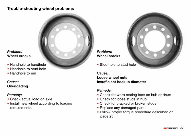
Problem:Wheel cracks
• Handhole to handhole• Handhole to stud hole• Handhole to rim
Cause:Overloading
Remedy:• Check actual load on axle• Install new wheel according to loading
requirements.
Problem:Wheel cracks
• Stud hole to stud hole
Cause:Loose wheel nutsInsufficient backup diameter
Remedy:• Check for worn mating face on hub or drum • Check for loose studs in hub• Check for cracked or broken studs• Replace any damaged parts• Follow proper torque procedure described on
page 23.
Trouble-shooting wheel problems

2 NUTSSYSTEM HUB STD
SPINDLETHREAD
Lubricatespindlethread
Nutpreparation
Removethe keeper
from the nut
Inner Nut
Fine
Coarse
PRO-TORQNUT SYSTEM
HUBCONMETPRESET
Fine orCoarse
yes
yes
Bolt
+ 200lbs-pi
-1 turn
Nobackoff
+ 300lbs-pi
Un-bolt Bolt
+ 50lbs-pi
Release
- 1/4turn
- 1/8turn
A. B. C.
HUB STDFine
Coarse
HUBCONMETPRESET
Fine orCoarse
yes
yes
Spindle axle nut instructions
26

yes
yes
Lockwasher
(Peak facing exterior)
D.Verification
Make sure that the wheel
turns freelyafter each spindle nut tightening
I.Lockingdevice
Install thekeeper
(orange sidefacing out).The keywaytang must be
in the axlekeyway
Bend 2 starsof the star
washertowardsouter nut
G.
0.001 to 0.005
0.000 to 0.004
0.001 to 0.003
0.001 to 0.003
Acceptableend play
(in)
H.Star
washer
yes
yes
E.
+ 300lbs-pi
Outer Nut
Bolt
+ 350lbs-pi
Nobackoff
- Backoff until
it isloose
Nobackoff
Nobackoff
+ 200lbs-pi
+ 200lbs-pi
+ 100lbs-pi
(*5 times)
Un-bolt Bolt Release
-1/10 turn(1/10=1 stud)
- ? turn
F.
27

Wheels
28
Oil lubricated wheel bearing
Check hub gaskets and seals for oil leaks prior to eachtrip. Leaking seal can result in ruined wheel bearingsand possible failure of the axle-wheel assembly.
Check oil level in hubs prior to every trip. Add oil whenlevel is low, only to the level indicated by the mark onthe hub cap. Too much oil can damage the wheelbearings. Use synthetic oil grade 50 (transmission), oran equivalent mineral oil based product.
CautionCracked wheels, loose lug nuts or missing studs are extremely hazardous conditions that are likely
to cause accidents or breakdowns.
OIL LEVEL LINE

12
6
39
29
Grease or semi-fluid grease wheel bearing
Manac recommends, as a minimum, during routine PMservice, to inspect the inner side of the hub for obviousleakage. Correct leakage problem if occuring. Also, itis necessary to insure, at every 60 000 miles, that theouter bearing is getting lubricated and that there isenough grease in the hub. This is especially importantwith the wheel-end systems using the smaller outerbearing. A visual inspection through the inspectionplug or after removing the hubcap should be made. Ifinadequate grease is suspected (obvious lack ofgrease) pull the outer bearing to make sure of anadequate amount of grease. Replenish if necessary. Ifthere is any sign of overheating or component damage,the wheel-end system should be redone.
Axle alignment
Axle alignment must be checked at regular intervals. Ifthe semitrailer is not tracking properly, this should bereported to the Maintenance Department.
GREASE LEVEL LINE

30
Check the equalizer to see that there are noobstructions to movement during operation. If equalizermovement is restricted by an obstruction, the axle“walk” will not be sufficient and damage will result.
Check wear pads in hangers. If they are wearingthin, install new wear pads or the spring will causepermanent damage to the hanger ifself. Do not operatewith broken spring leaves.
CautionBroken spring leaves, missing or loose U-bolts,
or other defective conditions likely to cause axle shift, are hazardous and likely to cause
accidents or breakdowns.
Leaf-spring suspensionLeaf-spring suspension

The air suspension height is controlled by a height control valve that maintains a constant semitrailerheight by pressurizing or exhausting air in the airsprings as needed to support the load being carried.
You must build up and maintain your semitrailer’s air pressure higher that 65 psi before operating the semi-trailer. The air protection valve won’t operate until youhave 70 psi in the system. This valve automaticallymaintains a safe air brake pressure higher than 70 psito even air loss due to a failure in the suspension system.
If an air-spring failure occurs on one side, it is recommended to completely deflate the suspensionand temporarily operate on the air spring’s internal rubber bumpers, to allow your semitrailer to be movedto the nearest shop for repairs.
To deflate or cut off the air pressure to the damaged airspring, disconnect the height control valve actuatinglevers from their link assemblies and rotate to the vertical down position.
Caution• Do not operate the vehicle without air pressure in the air springs.• A semitrailer parked for any length of time with a payload and supported by the landing gear legs should be
lowered on to the air spring internal bumpers.• For safe loading and unloading, lower the vehicle on to the air spring internal bumpers.
31

Quad axle unitAccording to regulations for quad axle unit, a ratiovalve may be required. This ratio valve manages theground pressure of the steering axle with the one ofthe tridem within 1 100 lbs. (500 KG). Check with yourState, Province, and/or Territory authority to know thelocal requirements.
The ratio valves are factory-calibrated, however werecommend testing the calibration twice a year.
Calibration procedure:
• To Localize the ratio valve (part no 223-626)usually mounted close by steering-axle.
• Install gauge on optional gauge port.
• Loose lock nut.
• Read pressure of tridem suspension bag. (P)
• Use the pressure (P) multiply by factor (F) obtainedfrom your Manac Service shop to find the ratio (R)pressure for your specific unit. (P x F = R)
• Turn clockwise or counterclockwise the adjustment screw until reading the pressure (R) on optional gauge.
• Make sure to tighten lock nut.
Note: This procedure must be done with loaded unit.
Air suspension
Lock nut
Adjustementscrew
Optional gaugeport
32

A
A = Ride height
A A
AIR RESERVOIR
AIR SPRINGS
HEIGHT CONTROL VALVE
BRAKE PROTECTION VALVE
A
Suspension inspection
During regular vehicle maintenance, visually inspectthe following items:
• all fasteners including the pivot bolts and U-bolts for security as applicable to your suspension
• all welds including axle connnection pivot, beam, bracket and frame attachment
• structure: integrity of vehicle frame, suspension beams and brackets
• broken or leaking shock absorbers • air springs for chafing, rubbing, or damage• air system valves, piping and fittings (see top figure)• suspension ride height (see bottom figure)
Suspension safety and inspection
33

Docking process
A-WITH auto reset
1. Once the semitrailer has been backed up to theloading dock, apply the semi-trailer’s parkingbrakes.
2. Manually activate the exaust valve inside control box. Begin the loading/unloading process as usual.
B-WITHOUT auto reset
1. Before backing up to the loading dock, manuallyactivate the exhaust valve.
2. Back the semitrailer up to the loading dock, allowingthe suspension to drain as you move backwards.
3. Apply the semitrailer’s parking brakes after the air pressure has been completely drained; chock the semitrailer wheels and begin the loading/unloading process as usual.
Note 1: If the semitrailer is equipped with an automatic exhaust valve, air in the suspension will be drained at the parking brakes application.
Prior To Loading, Unloading Or Prolonged Parking
In many cases, trailers that are equipped with air suspensions also incorporate valving that allows the suspension’s air pressure to be exhausted (dumped) for loading, unloading or when the semitrailer is parkedfor a prolonged period of time. The following steps describe a typical sequence of operations involving theuse of an automatically or manually controlled exhaust (dump) valve:
Note
Exhaust (dump) valve operation
34

Exhaust (dump) valve operation
35
Drive-out process
1. Couple the tractor and semitrailer, if needed.
2. Raise the support legs, if needed, prior to inflating the suspension’s air spring (bags).
3. Activate the exhaust (dump) valve.
4. Unchock the wheels, release the parking brakes and pull away from the loading dock after the semi-trailer reaches normal operating height.
Note 2: If the semitrailer is equipped with an auto-reset valve, air pressure in the bags will settle after taking offthe parking brakes.
Note 3: If the semitrailer is equipped with an automatic exhaust valve, air pressure in the bags will settle aftertaking off the parking brakes.
Note

If you believe that this vehicle contains a safety defect,you may contact the manufacturer, NHTSA or both.
This vehicle was designed and quality inspected toconform with industry standards and all applicableNational Highway Traffic Safety Administration safetystandards. Manac warrants this vehicle to be free fromdefects in materials and workmanship when manufac-tured. If you detect a defect that could cause an accidentor could cause injury or death, you should advise:
Oran, MO8593 State Highway 77P.O. Drawer KOran MO 62771 USAToll free: 1 800 545-5086T. : 573 262-2166F. : 573 262-3480
If you believe your vehicle has a defect which couldcause a crash or could cause injury or death, youshould immediately inform the National Highway TrafficSafety Administration (NHTSA) in addition to notifyingManac.
If NHTSA receives similar complaints, it may open aninvestigation and if it finds that a safety defect exists ina group of vehicles, it may order a recall and remedycampaign. However, NHTSA cannot become involvedin individual problems between you, your dealer, orManac.
To contact NHTSA you may either call the Auto SafetyHotline, toll free, at 1 (800) 424-9393 (or 202-366-0123)in Washington, D.C. area or write to: NHTSA, U.S.Department of Transportation, Washington, D.C.20590. You can also obtain other information aboutmotor vehicle safety from the Hotline.
Reporting safety defects
36

Oran, MO8593 State Highway 77P.O. Drawer KOran MO 62771 USAToll free: 1 800 545-5086T. : 573 262-2166F. : 573 262-3480