operator’s manual k2 combicutter -...
TRANSCRIPT

TKS Operator’s manual
1
K2 CombiCutter EN, issue 2 2013-06 988726
Operator’s manualK2
CombiCutter

TKS Operator’s manual
2

TKS Operator’s manual
3
CE – Declaration of conformityWe,T. Kverneland & Sønner AS,Kvernelandsvegen 100N-4355 KvernelandNorway
declare that the product:
TKS - K2 CombiCutter
has been built in conformity with the Machine Directive 2006/42/EC and meets the relevant fundamental health and safety requirements.
Kverneland, 20 June 2013
Tønnes Helge KvernelandGeneral Manager
Enter the serial number of the machine here:
T. Kverneland & Sønner AS, manufacturer of agricultural products, reserves the right to change the design and/ or specifi cation of its products without prior warning.This does not imply any obligation to modify previously supplied machines.

TKS Operator’s manual
4
GuaranteeThis TKS product is guaranteed against manufacturing and material defects for one year.
If the owner wishes a defect to be covered by the product guarantee, he or his representative must inform the dealer of this when ordering parts and/ or repairs. Claims must be reported within the guarantee period.The dealer must complete a claims form for each case covered by a guarantee and send it to TKS or TKS’s distributor/ importer within the 10th of the month following the one in which the defect was reported.The defective parts shall be marked with the claim number and be kept for up to 6 months so that TKS or TKS’s distributor/ importer can inspect them.Since TKS products are used outside the manufacturer’s control, we can only guarantee the product quality, and not that it will perform its function, nor are we liable for any consequential damage.
The guarantee is not valid if: a) third party spare parts are used, or the product is repaired or altered without the approval of TKS. b) the operating and servicing instructions have not been followed. c) the machine has been used for other purposes than those for which it is designed. d) the damage occurs as a result of external forces such as high voltage fl uctuations due to a low supply voltage, lightning or other electrical phenomena.
The guarantee does not cover damage due to normal wear and tear.Offi cial safety regulations specify requirements that apply to the users/ owners and manufacturers of this machine, relating to the careful review of safety hazards that may arise when this type of machine is used correctly. Therefore, TKS and our importer/ distributor are not responsible for the functioning of components that are not shown in the spare parts catalogue for this product. TKS reserves the right to change the design of the product without this implying any obligations in relation to previously supplied machines.
NB! It must be possible to identify all enquiries relating to this product by the product’s serial num-ber; see page 8 on Machine identifi cation.
TKS Operator’s manual
5
ContentCE - Declaration of conformity . . . 3
Guarantee. . . . . . . . . . . . . . . . . . . 4
Introduction. . . . . . . . . . . . . . . . . . 7
Machine identifi cation. . . . . . . . . . 8
Dimensions wide CombiCutter . . 9
Dimensions narrow CombiCutter 10
Important dimensions when . . . . . .
installing a K2 CombiCutter . . . . 11
Technical data . . . . . . . . . . . . . . 18
Model description . . . . . . . . . . . . 19
Safety . . . . . . . . . . . . . . . . . . . . . 20
1 Installing the rails . . . . . . . . . . . . . . . . 26
1.1 Recommended rail sizes on . . . . . . . . .
1-rail suspension . . . . . . . . . . . . . . . . 27
1.2 Recommended rail sizes on . . . . . . .
2-rails suspension. . . . . . . . . . . . . . . . . . . 27
2 Installing a ceiling-mounted
K2 CombiCutter . . . . . . . . . . . . . . . . . 28
2.1 Ceiling-mounted unit on . . . . . . . . . . . .
2 rails IPE 120 . . . . . . . . . . . . . . . . . . 28
2.2 Ceiling-mounted unit on . . . . . . . . . . . .
1 rail . . . . . . . . . . . . . . . . . . . . . . . . . . 28
2.3 Turning corners on a rail . . . . . . . . . 29
2.4 Installing a stationary machine . . . . 30
2.5 Installing the power supply . . . . . . . 31
2.6 Installing a power cable on a wire . . 32
2.7 Cable drum. . . . . . . . . . . . . . . . . . . . 32
2.8 Cable carriages . . . . . . . . . . . . . . . . 32
2.9 Conversion of traverser carriage . . . . . .
on rail with points. . . . . . . . . . . . . . . . 33
3 Installing the power supply . . . . . . . . 34
3.1 Copper wires 400V/230V . . . . . . . . . 36
3.2 Installing the conductor rail. . . . . . . . 37
3.3 Conductor rail with end joint . . . . . . . 38
3.4 Conductor rail with . . . . . . . . . . . . . . . .
central connection . . . . . . . . . . . . . . 45
4 Installing traverser carriages . . . . . . 48
5 Attaching the cart . . . . . . . . . . . . . . . 49
5.1 Installing the safety chain . . . . . . . . . 51
6 Installing equipment on traverser . . . .
carriages on 2-rails . . . . . . . . . . . . . . . 52
7 Installing the reservoir . . . . . . . . . . . . 55
8 Use of the machine. . . . . . . . . . . . . . . 57
9 The CombiCutter control . . . . . . . . . . 58
10 Wireless radio I/R operation K2 . . . . 59
10.1 I/R operation K2 for all functions . . . 60
11 Autofi lling K2 CombiCutter. . . . . . . . 62
12 Multi -function time relay . . . . . . . . . 64
12.1 Frequency converter. . . . . . . . . . . . 64
12.2 Motor protection device . . . . . . . . . . .
for Cutter motor . . . . . . . . . . . . . . . . . 65

TKS Operator’s manual
6
13 Frequency converter . . . . . . . . . . . . . 66
13.1 Programming and operating. . . . . . . . .
the converter. . . . . . . . . . . . . . . . . . . 67
14 Circuit diagram . . . . . . . . . . . . . . . . . 69
15 Troubleshooting the CombiCutter . . 75
16 Maintenance and care . . . . . . . . . . . . 76
17 Model description and area of . . . . . . .
use on the spreader unit. . . . . . . . . . 84
18 Use of the machine w/spreader unit 86
19 Main measurement for machine. . . . . .
with spreader unit . . . . . . . . . . . . . . . 88
20 Width adjustment on spreader unit . 89
21 Remote control . . . . . . . . . . . . . . . . . 90
22 Use of adjusment on spreader unit . .
med radiostryring . . . . . . . . . . . . . . . 91
23 Maintenance and care. . . . . . . . . . . . 92
24 Circuit diagram . . . . . . . . . . . . . . . . . 93
24.1 Circuit diagram for spreader unit . . 97
24.2 Circuit diagram for autofi lling. . . . . . 98
Recycling - waste to resource - . . . . . . . . 101
Notes . . . . . . . . . . . . . . . . . . . . . . . . . . . . 103

TKS Operator’s manual
7
IntroductionCongratulations on buying your new TKS product. You have chosen a functional, high quality product. A network of helpful dealers will be able to advise you on its use, as well as provide servicing and spare parts.All TKS products are designed, tested and built in close cooperation with farmers and machine workshops to ensure optimal effi ciency and reliability.
Please read this instruction manual carefully and familiarise yourself with the machine‘s manner of operation before starting to use it. There are many conditions and variables that can affect the machine’s functionality and manner of operation. It is therefore vital that you consider all known conditions and adapt usage according to these. A good understanding of the machine‘s manner of operation and performance, together with a high degree of knowledge with regard to feeding and feed types/consistencies will ensure the best possible result. The machine is a highly advanced feed robot that operates without the need for supervision and must be used in accordance with the applicable instructions from the manufacturer and other regulations in force at any given time.
By being thorough and making the necessary adaptations to local conditions, you will ensure the best possible results.
Yours faithfullyTKS AS
T. Kverneland & Sønner AS,Kvernelandsvegen 100N-4355 KvernelandNorway
www.tks-as.noe-post : [email protected] : + 47 51 77 05 00Fax : + 47 51 48 72 28

TKS Operator’s manual
8
Machine identifi cationThe machine’s serial number and the address of the manufacturer are written on the machine. See the illustration on this page.Please use the information on the name plate when making any enquiries about spare parts or servicing.This product is CE marked. This mark, along with the associated written EU confi rmation, means that the product fulfi ls current health and safety requirements, and complies with the following directives: Machine Directive 2006/42/EC
IKO2_40

G
A
B CD
E
FK L
HI
M N
J
P
QR
TKS Operator’s manual
9
Dimensions wide CombiCutter
K2_02
All measurements are in mm
MM
A1 2670 TROLLEY (SHORT)
A2 3170 TROLLEY (LONG)
B 1185 INTERNAL
C 1580 HEIGH STD.
D1 2250 INTERNAL (LONG)
D2 1750 INTERNAL (SHORT)
E1 2922 EXTERNAL (SHORT)
E2 3422 EXTERNAL (LONG)
F 1354 INTERNAL
G 1590 EXTERNAL
I 4624 EXTERNAL 1M SECTION
J 3448 INTERNAL M. 1M SECTION
K 952 INTERNAL
L 1185 INTERNAL
M 1470 EXTERNAL
N 1755 MASHINE + CROSS CONVEYOR
P 550 WORKING HEIGHT BRUSH
Q1 400 LOADING HEIGHT WITOUT/CROSS CONVEYOR (SHORT)
Q2 780 LOADING HEIGHT W/CROSS CONVEYOR (LONG)
R 1800 BEAM WIDTH

A
B
C
C
D
TKS Operator’s manual
10
Dimensions narrow CombiCutter
K2_14
All measurements are in mm
MM
A 2244 INTERNAL
B 1202 INTERNAL
C 1202 EXTERNAL
D 964 INTERNAL

1630
1500 C-C
1660
947
732
195
0
715
3049 (LANG 3549)2439
145
5 190
0
3620 Long3120 Short
300
300
300
3300
2950
3620
2200
1250
55025
0
300
300
2200 Long1700 Short
TKS Operator’s manual
11
Important dimensions when installing a K2 CombiCutter
Floor-cart
IK1_01
2100
2-r
ails
2300
1-r
ail
3300 Long2800 Short
IK1_05
200
500-
700 25
0-45
0
TKS Operator’s manual
12
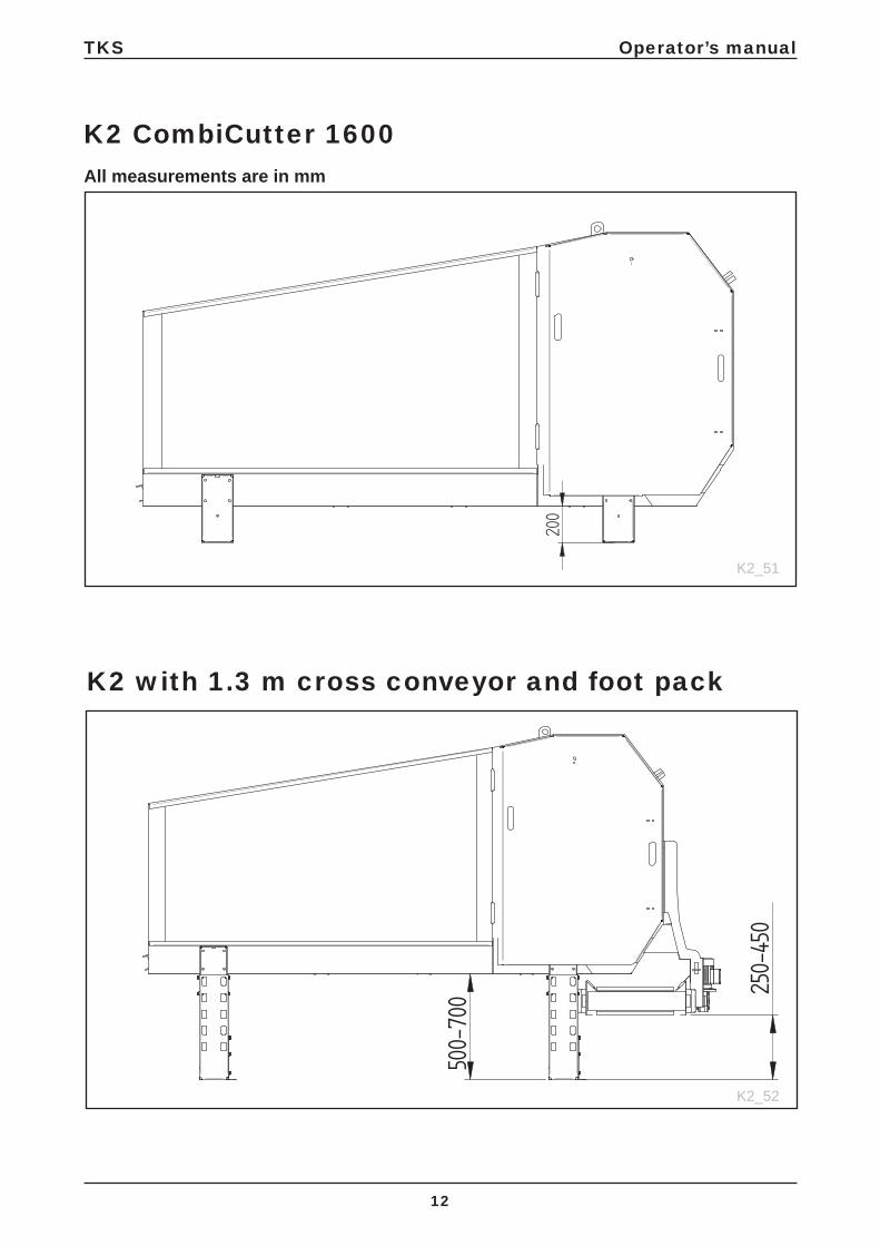
All measurements are in mm
K2 CombiCutter 1600
K2 with 1.3 m cross conveyor and foot pack
K2_51
K2_52

1000
-120
0
750-
950
11001360
TKS Operator’s manual
13
K2/R2 with frame cross conveyor
K2/R2 with frame, cross conveyor and conveyor
K2_53
K2_54

1
3
24
TKS Operator’s manual
14
K2 with weighing cell unit1 Weighing cell amplifi er2 Weighing cell foot3 Junction box 4 weighing 4 10 m cable, shielded 4x0.25
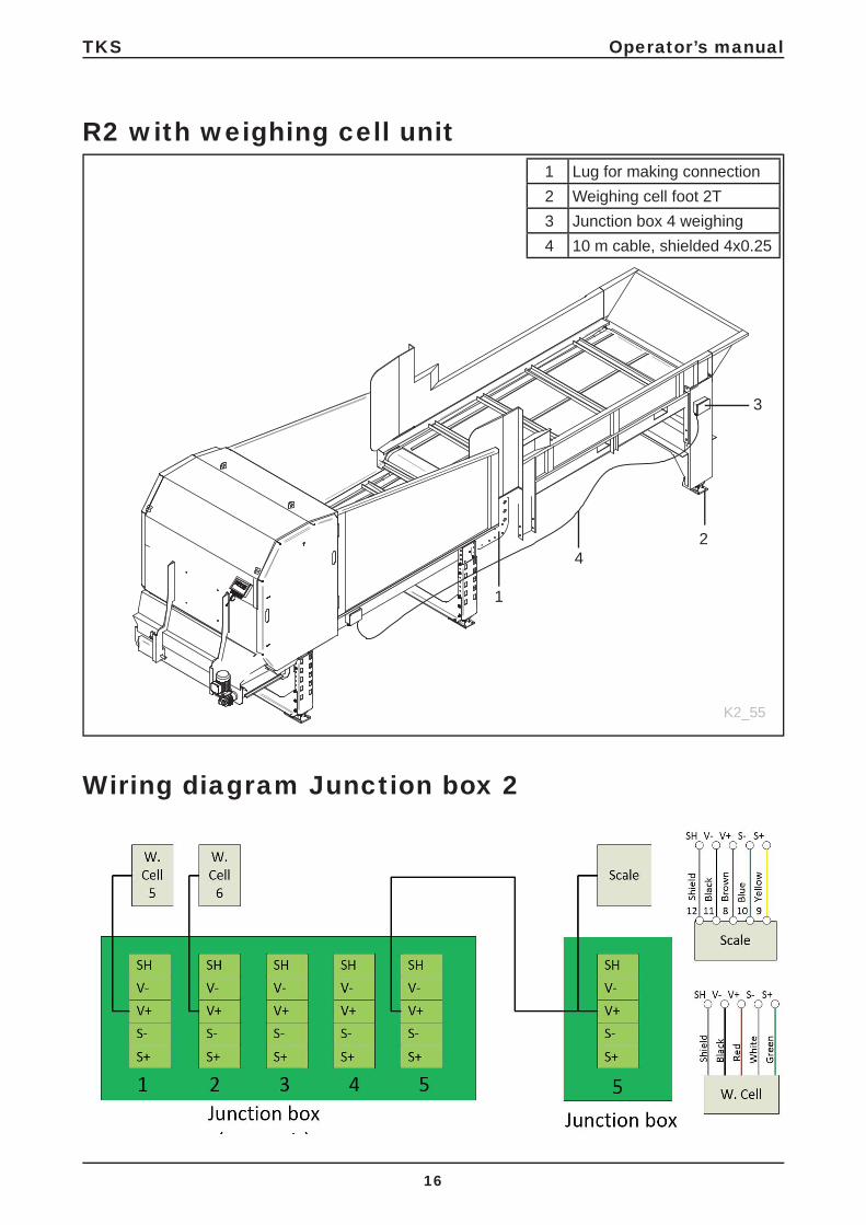
Wiring diagram Junction box
K2_55

TKS Operator’s manual
15
Confi guring the weighing cell amplifi erCode Value Function3 15 Filter4 150 Max. change in kg23 4 Number of weighing cells26 2000 Weighing cell capacity 2,000 kg32 0 Min. voltage34 U Voltage output (0–10 V)38 8000 Max. weight24 2 Convert mV to kg20 100 Empty weight. 10049 7 Measure frequency
1
2
3
4
TKS Operator’s manual
16
K2_55
R2 with weighing cell unit
Wiring diagram Junction box 2
1 Lug for making connection2 Weighing cell foot 2T3 Junction box 4 weighing 4 10 m cable, shielded 4x0.25
TKS Operator’s manual
17
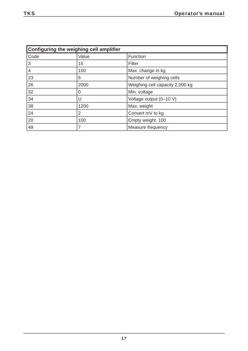
Confi guring the weighing cell amplifi erCode Value Function3 15 Filter4 150 Max. change in kg23 6 Number of weighing cells26 2000 Weighing cell capacity 2,000 kg32 0 Min. voltage34 U Voltage output (0–10 V)38 1200 Max. weight24 2 Convert mV to kg20 100 Empty weight. 10049 7 Measure frequency

TKS Operator’s manual
18
Technical data
WEIGHT K2 CombiCutter SHORT 1100 Kg
WEIGHT K2 CombiCutter LONG 1160 Kg
POWER
CONVEYOR BELT 0,55 KW (FREQUENCY- POWERED
SHREDDER DRUM 7,5 KW
CROSS CONVEYOR 0,9 KW
CEILING RAILS (X2) 0,40 KW (FREQUENCY- POWERED
MOTOR FOR FEED BRUSH 0,4 KW
ELECTRICITY
CONTROL CURRENT 24 V (DC)
VOLTAGE 230/240 V (N/BY 400V)
VOLTAGE TOLERANCE +/- 10%
CURRENT CONSUMPTION 230 V 30 RATED CURRENT TOT. RECOMMENDED FUSE 40 A
CURRENT CONSUMPTION 400 V 25 RATED CURRENT TOT. RECOMMENDED FUSE 30 A
FEED INDICATOR - CONVEYOR BELT SHREDDER DRUM MEASUREMENT

TKS Operator’s manual
19
Model description and area of useThe TKS CombiCutter has been designed to shred/ cut silage, round bales, square bales and most types of forage. The machine can be delivered as a stationary machine (placed over a feed hatch or on its own stand).It can also be supplied as a cart that runs along the fl oor or for mounting on ceiling rails. These versions have two speeds.
The CombiCutter has a 750 mm diameter drum. It also has a rotating conveyor belt. The machine is supplied with a standard knife-set:1600 = 62 knifes1200 = 24 knifes
The K2 CombiCutter shreds/ cuts most types of round bales and silage, with the size it cuts to being dependent on the consistency and nature of the feed.
The machine runs very silently, and due to its large drum the main engine only requires 7.5 kW of power. The conveyor belt has its own geared engine. The speed of the conveyor belt can be adjusted using an converter. This gives you a lot of fl exibility. The conveyor belt can be adjusted to the correct pressure against the drum for whatever type of feed. The machine can be equipped with optional side doors when you want to load it with feed. The machine’s control panel is at the front, but during operation it can be pulled out so that you can run the machine at the same time as seeing what is happening to the feed.
NOTE! The recommendations contained in this instruction manual are based on normal use. Individual users may encounter situations that require a different approach from the guidelines given here. Changes to the machine and equipment as a result of such situations do not give grounds for claims against the manufacturer or supplier.
The climate, temperature, type of grass, time at which it was cut, baling equipment and conservation method used are some of the issues that may affect the functioning and performance of the machine. It is important to make any necessary adjustments, and to set up the machine for the relevant conditions.This will produce the best possible results.
Extra equipment:Cross conveyor: 0,7m (K2 1200) - 1,0m - 1,3m - 1,7mDouble feedbrushSection extension - wide and narrowPendant controlPowered ceilingsFloor cartAuto controlMagazine

TKS Operator’s manual
20
Safety Please pay particular attention to this symbol. It means that there is a safety risk, and describes precautions that should be taken in order to avoid accidents.
Before operating, adjusting or repairing the machine, the user, technician or owner should familiarise himself with the safety instructions contained in this installation manual.Pay attention and be careful when handling agricultural machinery. Read and take note of the safety instructions in this manual.
Safety at work is your responsibility!
General safety instructions
Please read and understand these general safety instructions.
There is a risk of stones being thrown upwards and backwards when the machine is in operation.
Use of the machineThe machine must only be used for the purpose for which it is designed.
OperationThe operator of the machine must stay at the end of the machine where the control panel is located.
Providing notifi cation in the barnThe operator must familiarise himself with how the machine works and functions, so that it can be used safely and properly.
How the machine worksThe operator must familiarise himself with how the machine works and functions, so that it can be used safely and properly.
Keep a safe distanceHumans and animals must be kept away from the machine when it is in operation.Keep your distance from working, rotating and moving parts.
Be safety consciousNever enter the machine when it is in operation. When performing maintenance, disconnect the power supply.

TKS Operator’s manual
21
GuardsCheck that all shields are sound and correctly installed. Do not start the machine before doing this. Damaged screens must be repaired or replaced immediately.
Spare parts For safety reasons we recommend that you only use original spare parts. The use of third-party spares invalidates the product guarantee.
MaintenanceEnsure that the machine is properly maintained and is kept in good condition. Never attempt to change the mechanical workings of the machine.
The area in which the machine is operating Must be physically sealed off or locked to prevent danger to humans or animals.
Control panelThe power supply must be cut off before opening the panel.
Direction of rotationThe arrow (A) indicates which way the drumrotates.The sticker indicating the rotational direction ofthe drum should be put on the left-hand side.
NOTE!If the rotational direction is wrong, you mustswitch two phases in the main power supply.
IK1_02
A

TKS Operator’s manual
22
Additional safety instructions
The machine is marked with warning signs. If these signs are damaged, they must be replaced. The order number is shown on the illustrations in this section. See Fig. 6 for their location on the machine.
Warning sign UH220532 (Fig. 1)Caution! Read and understand the instruction manual before using the machine, and before making any adjustments or performing any maintenance.
Warning sign UH220544 (Fig. 2)Risk of crushing injury. Keep a safe distance from the area between the Kombikutter and reservoir.
Warning sign UH220526 (Fig. 3)You may damage your fi ngers if you trap them between the chain and the chain wheel.
Warning sign UH220527 (Fig. 4)Risk of cutting your hand. There is a risk of cutting your hand on the drum’s knives when the drum is in operation.
Warning sign UH220539 (Fig. 5)Risk of breaking your fi ngers. You risk breaking your fi ngers if you trap them between the conveyor and the base.
Fig. 1
Fig. 2
Fig. 3
Fig. 4
Fig. 5

TKS Operator’s manual
23
988010
Fig. 6
Warning sign 988010 (Fig. 6)NB! The conveyor belt must be kept tight, andthe screws on the belt must be retightened.

UH220544
UH220532
UH220526
UH220527
UH220539
UH220539
988010
UH220544
988010
UH220307
UH220307
UH220527
UH220307
TKS Operator’s manual
24
Overview of safety risks
IKO2_03
Fig. 7

TKS Operator’s manual
25
Lifting the machine with a crane
Only use approved lifting equipment.The machine must be lifted from the points marked with a lifting symbol.
Caution! Ensure that no-one is under or close to the machine when it is being lifted.Lift the machine using a strap attached to the main frame of the machine, so that the lift is balanced. Check that the straps are properly fi xed before starting the lift.Use an extra strap to help keep the machine in position.
New machine – caution
Read the instruction manual. Be particularly careful when starting a new machine for the fi rst time. Installationfaults.Be particularly careful when starting a new machine for the fi rst time. Installation faults, incorrect operation, etc. may lead to expensive repairs and loss of earnings. The TKS product guarantee does not cover damage resulting from failure to follow the recommendationscontained in the instruction manual.Please pay particular attention to this symbol. It is used to highlight important information, to help prevent incorrect installation andoperation.
Pay particular attention to the following when commissioning a new machine:Check that the machine is correctly installed and that it is not damaged. Check that electric cables are long enough and positioned such that they can follow the movements of the machine without being damaged.
Lubricate the machine where shown in Section 14 on Maintenance.
1440
TKS Operator’s manual
26
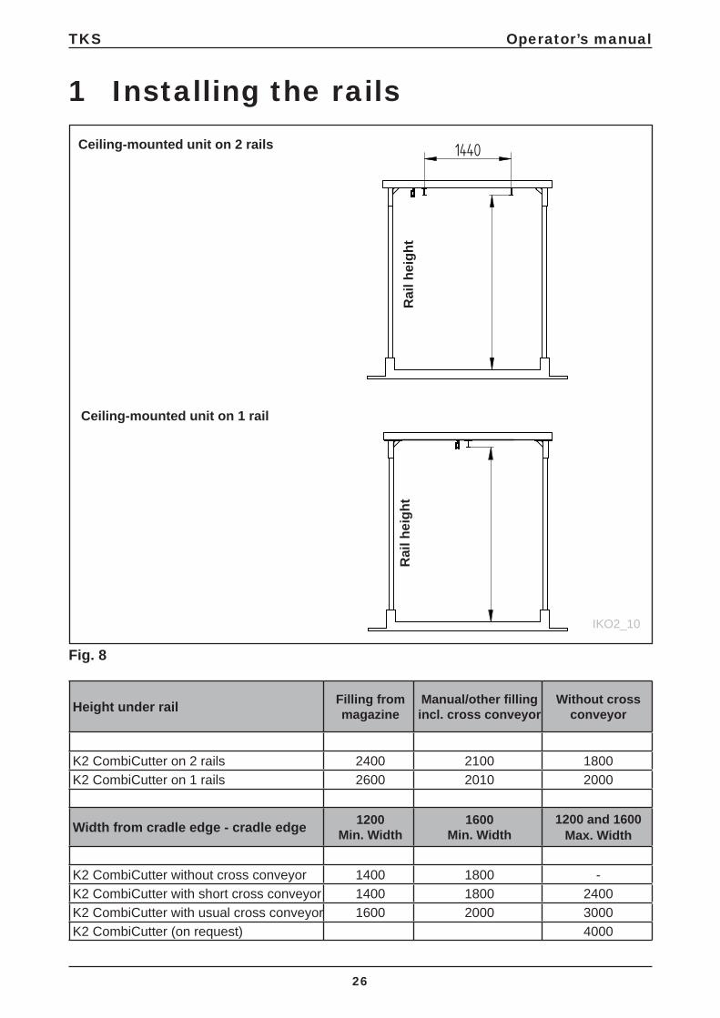
1 Installing the rails
Rai
l hei
ght
Height under rail Filling frommagazine
Manual/other fi lling incl. cross conveyor
Without cross conveyor
K2 CombiCutter on 2 rails 2400 2100 1800K2 CombiCutter on 1 rails 2600 2010 2000
Width from cradle edge - cradle edge 1200Min. Width
1600Min. Width
1200 and 1600Max. Width
K2 CombiCutter without cross conveyor 1400 1800 -K2 CombiCutter with short cross conveyor 1400 1800 2400K2 CombiCutter with usual cross conveyor 1600 2000 3000K2 CombiCutter (on request) 4000
Rai
l hei
ght
Fig. 8
IKO2_10
Ceiling-mounted unit on 2 rails
Ceiling-mounted unit on 1 rail

TKS Operator’s manual
27
Rail size Length between portalIPE 120 Max 1,5 m (Not recommended from TKS)IPE 160 Max 3,5 mIPE 220 Max 5,0 m
1.1 Recommended rail sizes/portal spacing on 1-rail suspension
1.2 Recommended rail sizes/portal spacing on 2-rails suspension
M6 M8 M10 M12 M16 M20 M22 M24
1,1 kpm 2,8 kpm 5,2 kpm 9,1 kpm 22,6 kpm 44,0 kpm 59,7 kpm 76,0 kpm
For other rail portals please contact TKS
Rail size Length between portalIPE 120 Max 3,0 mIPE 160 Max 5,0 mIPE 220 Max 7,0 m
Torque for K80 bolts (8.8)
Important notes regarding assembling of TKS’ monorails• The rail must be dimensioned to accord with the load (P) and the suspension distance (I), and must be checked for any wheel pressure restriction.• The building structure must be able to bear the load of the rail system in question. • The TKS rail system comes with full strength in the joints (IPE120/160).
When TKS rails are used in rail tracks, most of the attachment points must be on the lower face of the rail. For rail tracks with a bend, there must be a suspension at the beginning, middle and end of the bend.
Important: It is important to regularly check the tightening torque of bolt connections. (at least once a year).

TKS Operator’s manual
28
Fig. 9
Fig. 10
2 Installing a ceiling-mounted K2 CombiCutterIf the Kombikutter is delivered for ceiling mounting, it is fi tted with trolley attachments. The trolleysare supplied separately. When installing, the rails must be fi tted fi rst. See the brochure on“lifting equipment” for advice. Then the trolleys are threaded on to the rail. Fit end stoppers to the ends of the rail. Then hang the machine from the trolleys. Ensure that the Kombikutter cannot drive so close to the end wall that it constitutes a risk of crushing injuries. Use a padded buffer.Finally install the power supply as appropriate.
2.1 Ceiling-mounted unit on 2 rails IPE 120
Machine on the two rails will run only on the straight rails. If possible, therails can be hung directly from the ceiling, using the fi ttings that are most appropriate for your ceiling. If the ceiling cannot be used, you will need to install beams to hang the rails from; contact your dealer for details of systems and prices.The distance between fi xings can be 3.0 m for IPE 120 rails and 4.0 m for IPE 160 rails. Where the unit is lowered, it must be attached to the ceil-ing at all corners.The unit mounted on dual ceil-ing rails has 2 powered trolleys and 2 unpow-ered trolleys. The trolleys have two speeds. The standard speeds are 6/25 m/min. See Fig. 9
2.2 Ceiling-mounted unit on 1 rail
If mounted on a single rail, the unit can turncorners and cope with TKS points.NB! If you don’t achieve suffi cient power, you will need to reduce the speed, increase the engine size or use 4-wheel drive. It is important for their to be pressure on the drive wheels.Filling can be done on corners, arcs or using a rail opener. The rail can either be the IPE 160 with up to 3.5 m between fi xings or IPE 120 with up to 2 m between fi xings. To install the rails, use the TKS ceiling fi ttings for the relevant type of ceiling. The unit mounted on 1 rail has two powered trolleys.The trolleys have 2 speeds. The standard speeds are 6/25 m/min.See Fig. 10
IKO2_01
IKO2_01

DDD
B
C
A
C
A
TKS Operator’s manual
29
E
F
E
F
Short Long
A 200 cm 220 cm
B 100 cm* 120 cm*
C 100 cm* 120 cm*
D 280 cm 320 cm
E 160 cm 160 cm
F 200 cm 220 cm
Fig. 11
2.3 Turning corners on a rail
Measure the clearances very carefully. Build aframework of boards with the correct externaldimensions. See Fig. 11
*Minimum dimensions

TKS Operator’s manual
30
2.4 Installing a stationary machine
If the CombiCutter is to be used in a stationaryposition, it is normal to position the machineover a feed hatch so that you can release thefeed directly on to the feed tray. Alternativelyyou can build it up, so that it is possible to gainaccess under it with a wheelbarrow, wheeledgrab or fork. You can also use a grass conveyorbelt where appropriate.Install the machine somewhere that it will beeasy to load it with feed. It is usual to use a railsystem and a TKS electric hoist with a hook orhydraulic grab, a tractor with a spear for roundbales or similar to fi ll it with round bales.To make it easier to clean spillage from underthe machine, it is an advantage to raise themachine 10-15 cm up from the fl oor. Themachine is supplied with standard feet that canbe replaced.The machine must be fi rmly planted and positioned on a level surface.

TKS Operator’s manual
31
2.5 Installing the power supply
All electrical installation must be done by aqualifi ed electrician.Use power supply cables of a suitablediameter (at least 6 mm²).
Attention! Please remove the plug socket andassure that the fuse box is disconnected beforeopening it.The type of power supply you use should refl ectyour power requirements, the type of installation and any structural issues.The installation procedure for stationarymachines is simplest, requiring a socket for themachine’s power supply cable.
For carts that run along the fl oor, you can use a cable on a wire if the cart only runs in a straightline. A cable drum should be used if there arestraight sections and corners.
Ceiling-mounted units can be installed with all types of power supply.
NB!• It is essential for the drum to rotate in the
correct direction. See drawing• Damage caused by the drum rotating in the
wrong direction can lead to the V-belt coming off
• If the machine is started with the drum rotating in the wrong direction, open the cover and check the V-belt.
Power requirement of cable drum
Cable Drum
mm² Stretched out Max. 15m Max. 34m Max. 60m
4 x 6 40 A 15 - 35 A 34m - 30 A 60m - 25 A
Power consumption: 230V 400VFloor cart 2 X 1,5 kW 9,0 A 5,0 ACeiling-mounted unit 2 X 0,4 kW 4,0 A 2,5 ACutter engine (extra equipment) (5,5 kW) 21 A 15 ACutter engine 7,5 kW 27 A 18 AFeeder 0,55 kW 2,7 A 1,5 AFuse size 40 A 30 ACross conveyor 0,9 kW 4,5 A 2,5 A
TKS Operator’s manual
32
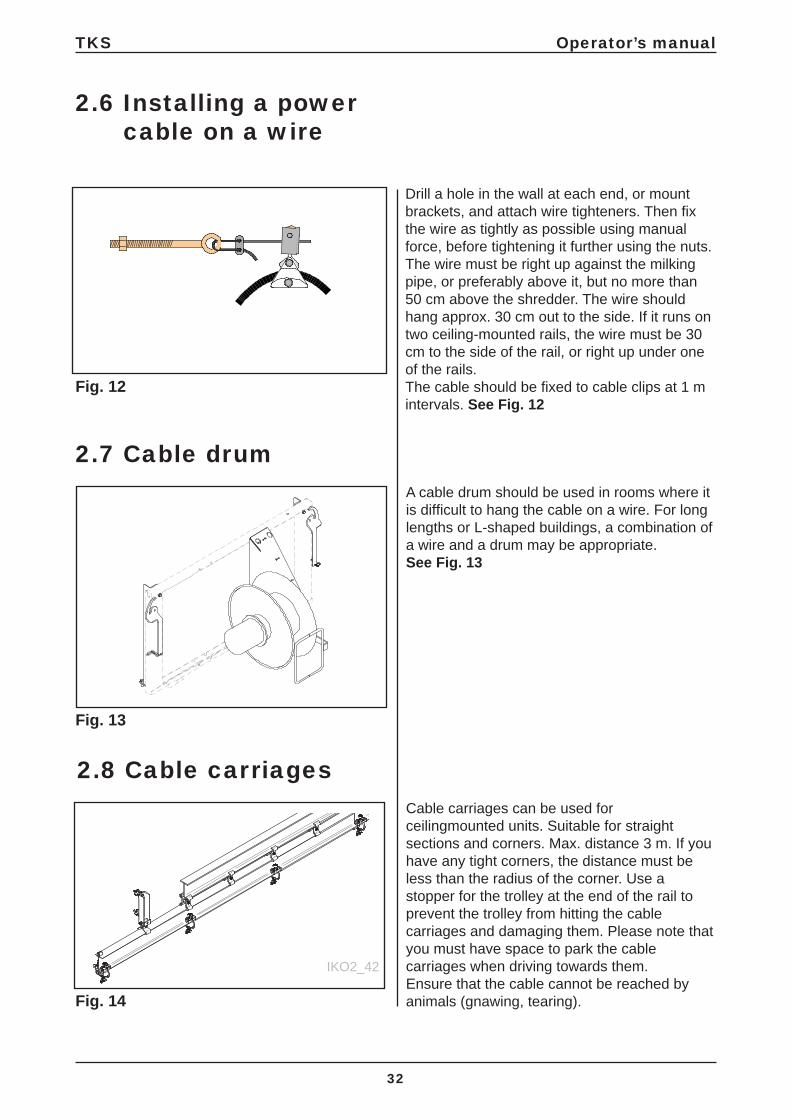
2.8 Cable carriagesCable carriages can be used forceilingmounted units. Suitable for straightsections and corners. Max. distance 3 m. If youhave any tight corners, the distance must beless than the radius of the corner. Use a stopper for the trolley at the end of the rail toprevent the trolley from hitting the cablecarriages and damaging them. Please note that you must have space to park the cable carriages when driving towards them.Ensure that the cable cannot be reached byanimals (gnawing, tearing).
2.6 Installing a power cable on a wire
Drill a hole in the wall at each end, or mountbrackets, and attach wire tighteners. Then fi xthe wire as tightly as possible using manualforce, before tightening it further using the nuts.The wire must be right up against the milkingpipe, or preferably above it, but no more than50 cm above the shredder. The wire shouldhang approx. 30 cm out to the side. If it runs ontwo ceiling-mounted rails, the wire must be 30cm to the side of the rail, or right up under oneof the rails.The cable should be fi xed to cable clips at 1 mintervals. See Fig. 12
2.7 Cable drumA cable drum should be used in rooms where itis diffi cult to hang the cable on a wire. For longlengths or L-shaped buildings, a combination ofa wire and a drum may be appropriate. See Fig. 13
Fig. 13
Fig. 12
Fig. 14
IKO2_42

A
B
C
TKS Operator’s manual
33
2.9 Conversion of traverser carriage on rail with points
In the case of a rail with points, you have to change to a different bracket: from A to B. See fi gures 1 and 3 (bracket supplied).• The motor has to be turned so that junction
box C faces downwards. See fi gures 3 and 4.
Bilde 1
Bilde 2
Bilde 3
Bilde 4

TKS Operator’s manual
34
3 Installing the power supplyThe most common and best method of supplying power to a K2 CombiCutter is to use powered rails. These consist of a rail with a copper strip on the inside, and a transformer (slide) that follows the unit during operation. See Fig. 15
The narrow fi xing must be attached every 2 meters on the rail. See Fig. 15b
IKO2_11
Fig. 15
Fig. 15b Fig. 15a

300
TKS Operator’s manual
35
The wide fi xing must be attached at the correct distance from the rail holding the traverse carriage.See Fig. 16
IKO2_12
Fig. 16

L3
V
L1
NL2
A
B
C
L3
V
L1
L2
A
B
L3
V
L1
L2
A
B
N
V
V
IK2_13
IK2_13
IK2_13
TKS Operator’s manual
36
Grounded (A) should be inserted where there is a yellow stripe (B) along the outside of the rail. The yellow stripe should be continuous along the entire length of the rail.
= GROUNDEDL1 = PHASEL2 = PHASEL3 = PHASEN = NEUTRAL CONDUCTOR V = HEATING
An additional safety bar (C) on the rail ensures that the current collector cannot be installed the wrong way around and cause a short circuit or incorrect impulses.
Each copper wire should be fi xed to the tightening screws in the switch box at the end, before an authorised electrician completes the rest of the process.
Incase of humid locations or temperature fl uctuations, heat trace cable should be installed.
Heat trace cable is fi tted in one of the rails marked V in center track.
Heating cables should be fi tted on one side only , and in the central track.
3.1 Copper wires 400V/230V
Fig. 17a
Fig. 17b
Fig. 17c
400V 3-pole + N (Straight rail)
400V curve 3 pole + N
230V 3 pole
Max. 2000mm Min. 500mm
B
A
TKS Operator’s manual
37
Fig. 18
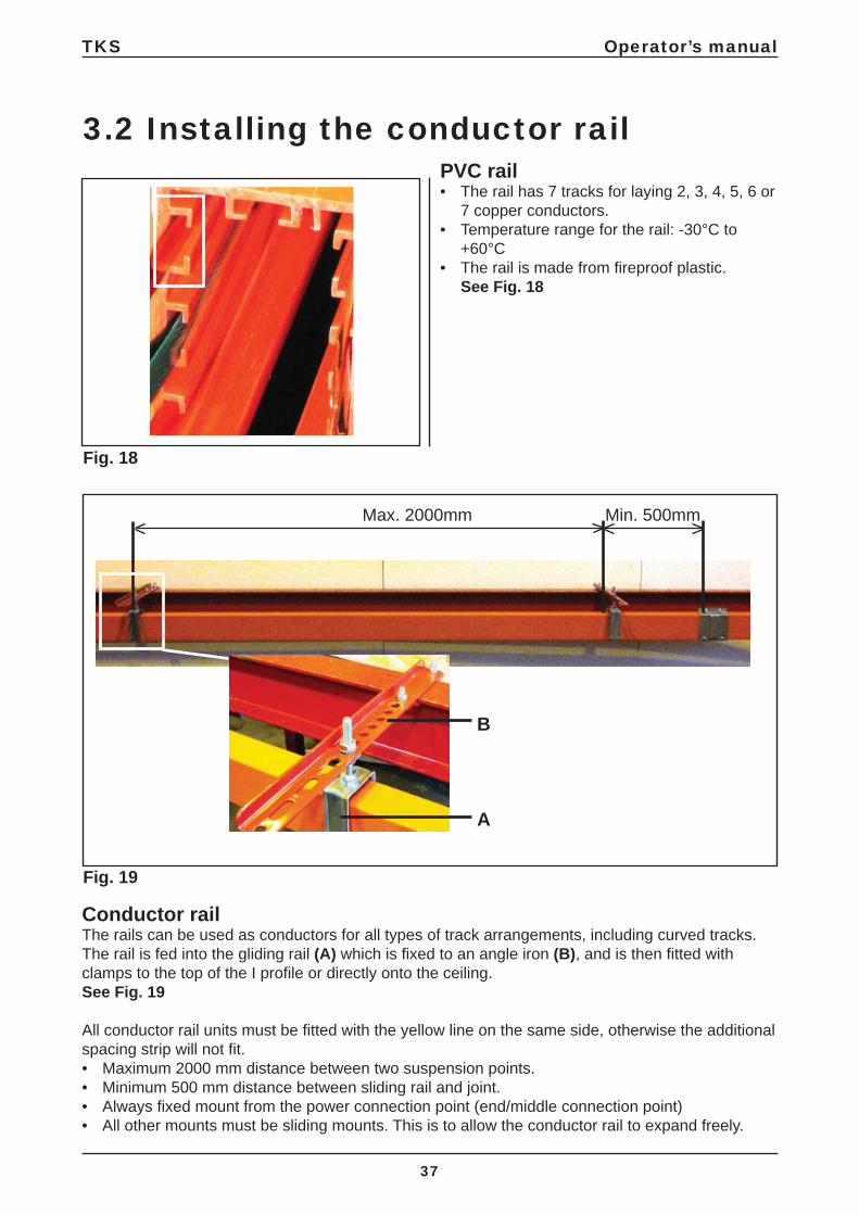
3.2 Installing the conductor railPVC rail• The rail has 7 tracks for laying 2, 3, 4, 5, 6 or
7 copper conductors.• Temperature range for the rail: -30°C to
+60°C• The rail is made from fi reproof plastic.
See Fig. 18
Conductor railThe rails can be used as conductors for all types of track arrangements, including curved tracks.The rail is fed into the gliding rail (A) which is fi xed to an angle iron (B), and is then fi tted with clamps to the top of the I profi le or directly onto the ceiling. See Fig. 19
All conductor rail units must be fi tted with the yellow line on the same side, otherwise the additional spacing strip will not fi t.• Maximum 2000 mm distance between two suspension points.• Minimum 500 mm distance between sliding rail and joint.• Always fi xed mount from the power connection point (end/middle connection point) • All other mounts must be sliding mounts. This is to allow the conductor rail to expand freely.
Fig. 19

TKS Operator’s manual
38
Fig. 21
3.3 Conductor rail with end joint
Fig. 20
T50 insulation tapeJoints between two rail lengths should be covered with T50 insulation tape. See Fig. 20
Joint clampThe joint clamp is fi tted with barbs that fi x the rail into position when the two parts are pushed together. This enables you to join the conductor rail together quickly and safely.Once the rail is in place we recommend that the current collector is laid through the rail to ensure that the joints are working properly, this must be done after the copper conductors are marked. Check that the track along the rail is clear and not distorted by the joint clamps (the track should be 10 mm). If necessary, you can adjust the track by bending the joint clamp until you achieve the required clearance. See Fig. 21

500mm
A
TKS Operator’s manual
39
Fig. 23
Fig. 24
Fig. 22
Angle ironThe rail is fi xed to an angle iron, which is then fi tted with clamps to the top of the I profi le or directly onto the ceiling. See Fig. 22
End jointsMove the sleeve to the end switch box at the end of the rail. See Fig. 23
SleeveOnce the sleeve has been positioned at the end of the conductor rail it must be fi xed using the appropriate screws (A).The distance between end terminal box and fi xed suspension should be 500 mm.See Fig. 24

TKS Operator’s manual
40
Fig. 26
Fig. 27
Fig. 25
TrolleyLay the copper wire from the end of the track using a trolley. The trolley is not supplied.
Picture 1 Attach the trolley to a ø6 hole in the copper wires.
Pictures 2–3 Feed the trolley into the conductor rail and pull it through the rail until it reaches the other side. See Fig. 25
Copper wiresThe trolley pulls the copper wires through the conductor rail until the bent end pushes against the rail. See Fig. 26
A
B
C
Copper wire connectionsThe copper strips are then connected to the various currents and their associated wires.See symbols and abbreviations for copper wires on page 29, Fig. 17a - 17b - 17c
A 400V 3-pole + NB 400V 3-pole + N (Straight rail)C 230V 3-pole
See Fig. 27
1
2
3

A
A
TKS Operator’s manual
41
Fig. 29
Fig. 28
Heating cableHeating cables with insulation strips are fed into the conductor rail. See Fig. 28The green insulation strip (A) must face inwards on the conductor rail.
Heating cable connectionsThe heating cable is connected to a terminal block with a 230V – 10/16A separate circuit.See Fig. 29
Suspension clampFit the fi xed suspension clamp (A) near the end joint. See Fig. 30

TKS Operator’s manual
42
Fig. 32
Fig. 33
Fig. 31
Fitting the rubber sealInsert the protective membrane rail into the horizontal track underneath the conductor rail either manually or, in the case of long pieces of membrane, by using specialist equipment (consult TKS).The rubber seal should be fi tted to both sides to achieve a better enclosure rating (IP44)See Fig. 31
Current collectorThe current collectors are inserted into the casing on the conductor rail. The current collector is controlled by a link bracket attached to the traversing carriage or trolley. Individual adaptation may be necessary depending on where it is located.
NB!Ensure the cable does not pull the current collector trolley askew.See Fig. 32
ChainOn each bracket a chain should be fi tted that will pull the collector horizontally. It is important that the chain pulls parallel with the opening in the conductor rail. See next picture.See Fig. 33

A
TKS Operator’s manual
43
Fig. 35
Fig. 36
Fig. 34
Even pull on the chainIt is important that the chain (A) pulls evenly (not skewed) and slightly downwards (1–3 cm).This is particularly important when operating in curves.See Fig. 34
Rubber sealEnsure that the inserting part of the rubber seal is laid inside the track on the end casing.See Fig. 35
End casingStraighten the construction and fi x the end casing using the appropriate screws.See Fig. 36

25mm
TKS Operator’s manual
44
Fig. 38
Fig. 37
Copper conductorsThe ends of the copper conductors should be cut 25 mm outside the rail. See Fig. 37
Conductor rail with end joint
ConnectorFit the end plug. Fix the joint clamp over the in-sulation tape and adjust it to obtain the required clearance.See Fig. 38
500mm 500mm
A
B
C
TKS Operator’s manual
45
Fig. 41
Fig. 39
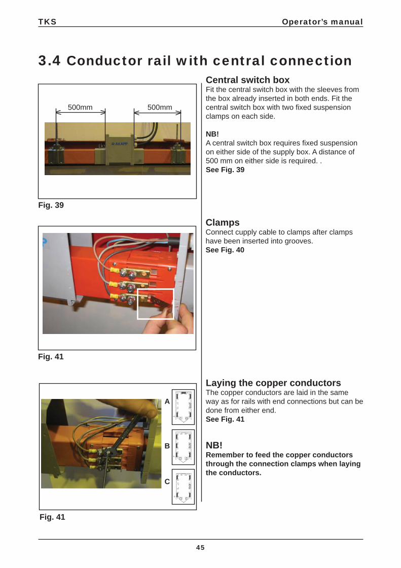
Central switch boxFit the central switch box with the sleeves from the box already inserted in both ends. Fit the central switch box with two fi xed suspension clamps on each side.
NB!A central switch box requires fi xed suspension on either side of the supply box. A distance of 500 mm on either side is required. . See Fig. 39
3.4 Conductor rail with central connection
ClampsConnect cupply cable to clamps after clamps have been inserted into grooves.See Fig. 40
Laying the copper conductorsThe copper conductors are laid in the same way as for rails with end connections but can be done from either end.See Fig. 41
NB!Remember to feed the copper conductors through the connection clamps when laying the conductors.
Fig. 41
25mm
TKS Operator’s manual
46
Fig. 42
Fig. 43
Fig. 41
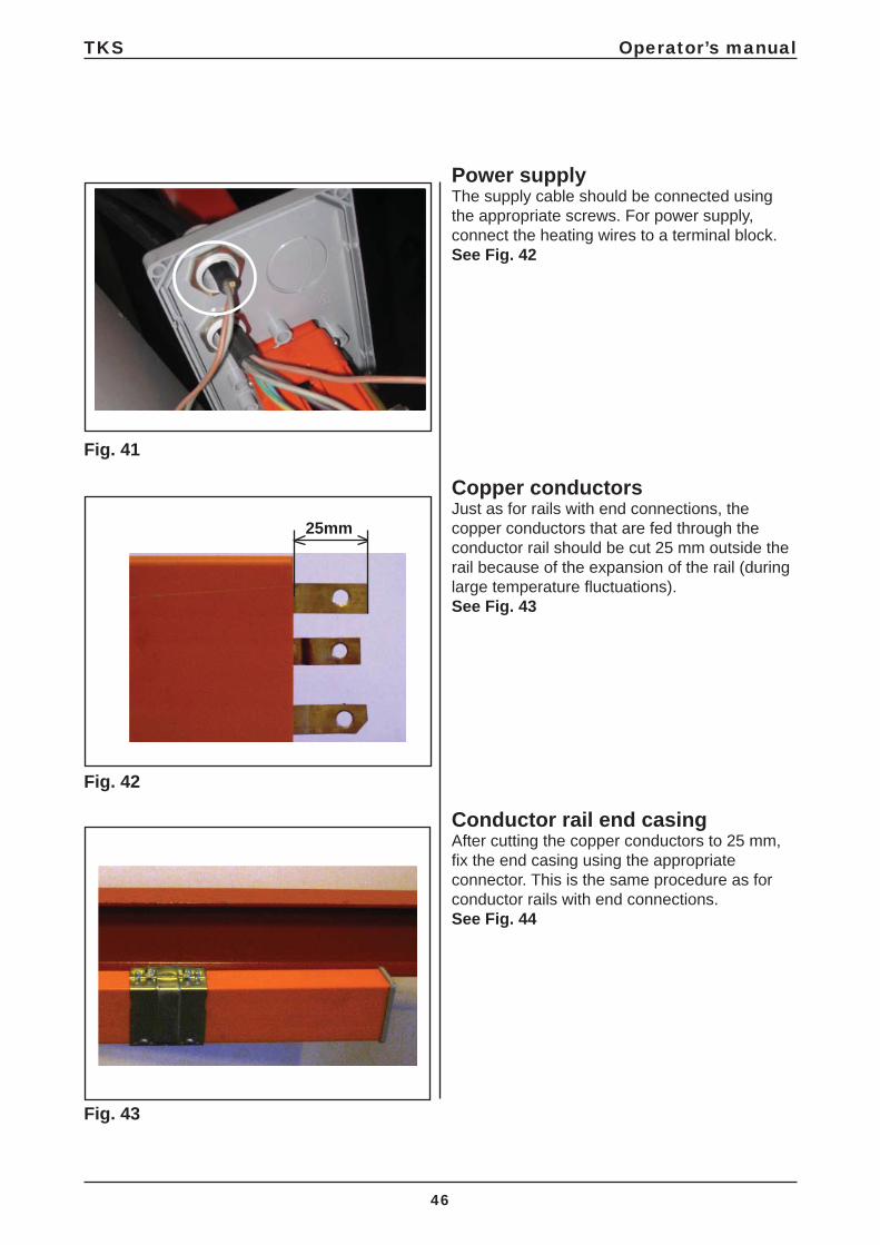
Power supplyThe supply cable should be connected using the appropriate screws. For power supply, connect the heating wires to a terminal block. See Fig. 42
Conductor rail end casingAfter cutting the copper conductors to 25 mm, fi x the end casing using the appropriate connector. This is the same procedure as for conductor rails with end connections. See Fig. 44
Copper conductorsJust as for rails with end connections, the copper conductors that are fed through the conductor rail should be cut 25 mm outside the rail because of the expansion of the rail (during large temperature fl uctuations).See Fig. 43

TKS Operator’s manual
47
Fig. 45
Fig. 44
Rubber sealInsert the rubber seal by hand or use specialist equipment in the case of long pieces. See Fig. 45
Central switch box The central connection should be fi xed to the conductor rail using the appropriate screws.See Fig. 46
Maintenance and inspectionIt is recommended that the current collector is inspected after 1 month of operation, then every 1000 km or once a year thereafter.
NB!Sweep the protective membrane along the conductor rail with a brush/sponge to prevent wear and verdigris on the copper conductors due to dust and moisture.

B
TKS Operator’s manual
48
4 Installing traverser carriagesThe traverser carriages for the cart are supplied loose. These are attached from the end of the rail. Motorised traverser carriages must be at the front of the cart. See Fig. 47
Fig. 47
IK2_18
REAR
FRONT

A
B
C
IK2_24
TKS Operator’s manual
49
Fig. 48
5 Attaching the cartBefore suspending the cart from the traverser carriages, it is a good idea to adjust the ceiling rails to the correct height, to avoid having to use a jack to adjust this later. Critical factors with regard to the istallation height are:• The longitudinal rail – or if applicable the buffer at the rear if the machine (1rail) – must
be a suffi cient height when the cart collects a new round bale from a reservoir.• The machine’s side dispenser must be at a suffi cient height to prevent it getting stuck in
the forage and forage movement.
Height from the base (sidewall) and up to the upper edge of the rail channel. This is an absolute minimum measurement. See Fig. 48
A = recommended measure 350mm B = recommended measure 500mm C = minimum measurement 1650 mm, applies to a round bale diameter of 1250 mm. This measurement increases for larger round bale diameters.Less risk of sealing between cross conveyor and machine
Double rail
L
TKS Operator’s manual
50
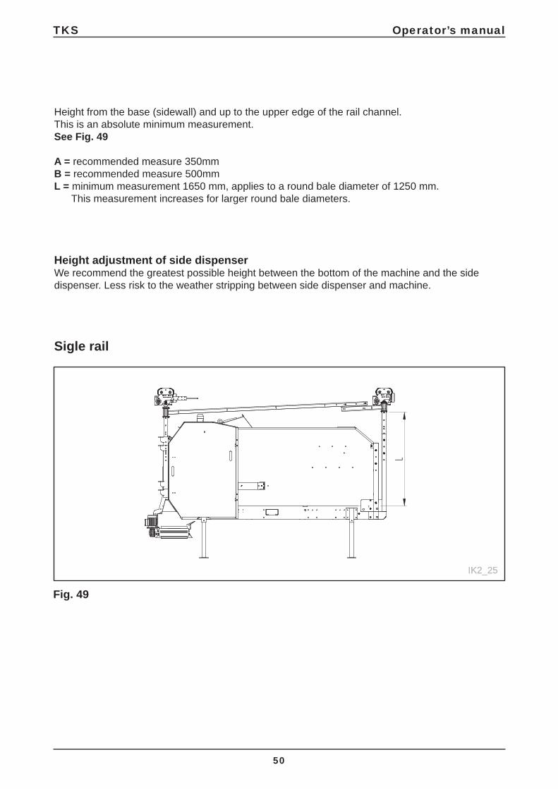
Height from the base (sidewall) and up to the upper edge of the rail channel. This is an absolute minimum measurement. See Fig. 49
A = recommended measure 350mmB = recommended measure 500mmL = minimum measurement 1650 mm, applies to a round bale diameter of 1250 mm. This measurement increases for larger round bale diameters.
Height adjustment of side dispenser We recommend the greatest possible height between the bottom of the machine and the side dispenser. Less risk to the weather stripping between side dispenser and machine.
Sigle rail
IK2_25IK2_25
Fig. 49

B
D
E
IK2_70
AC
TKS Operator’s manual
51
IK2_28
5.1 Installing the safety chain• The robot is screwed in place with bolt A in eye nut B • NB! There needs to be clearance between locknut C and pipe E• Tighten locknut C to eye nut B • To fi nish, secure the bolt using pin D
The cart should be screwed in place in both front and back with bolts in the eye nuts. Fit the chain through the pulley axle and boom. See Fig. 50

C
IK2_21
D
TKS Operator’s manual
52
Fig. 51a
6 Installing equipment on traverser carriages on 2-rails Several items has to be mounted to the trolleys. See Fig. 51
These items are:• Currency transformer for power supply through the powered rails• Bar connecting the front and back traverser carriages togetherThe back and front traverser carriages are
C CLAMP FOR POWER
D BRACE BAR
REAR
FRONT
FRONTREAR

IK2_22
C
D
TKS Operator’s manual
53
Installing equipment on traverser carriages on 1-rail
C CLAMP FOR POWER
D BRACE BAR
Fig. 51b
REAR
FRONT
FRONTREAR

IK2_19
IK2_20
IK2_23
A
TKS Operator’s manual
54
Fig. 52
Fig. 53
Fig. 54
Rear and front trolley are connected with a brace. The bar is fi rst attached to the traverser carriage, then the channels arescrewed to the outside of the bar. This onlyapplies to 2-rail systems. See Fig. 52
The clamp for the power transformer isattached. The bar provided is fi rst screwed tothe traverser carriage, and then the clamp isinserted into the threaded hole using pliers.See Fig. 53
A chain is attached to each arm to pull the transformer in a horizontal direction. It is important that the chain is straight (not bent) and that it hangs slightly downwards. See Fig. 54
IKO2_17
TKS Operator’s manual
55
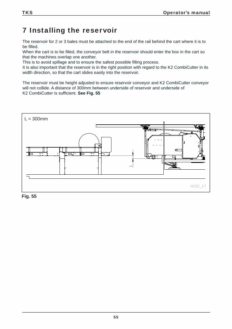
7 Installing the reservoirThe reservoir for 2 or 3 bales must be attached to the end of the rail behind the cart where it is to be fi lled.When the cart is to be fi lled, the conveyor belt in the reservoir should enter the box in the cart so that the machines overlap one another. This is to avoid spillage and to ensure the safest possible fi lling process.It is also important that the reservoir is in the right position with regard to the K2 CombiCutter in its width direction, so that the cart slides easily into the reservoir. The reservoir must be height adjusted to ensure reservoir conveyor and K2 CombiCutter conveyor will not collide. A distance of 300mm between underside of reservoir and underside of K2 CombiCutter is suffi cient. See Fig. 55
Fig. 55
L = 300mm
IK2_26
TKS Operator’s manual
56
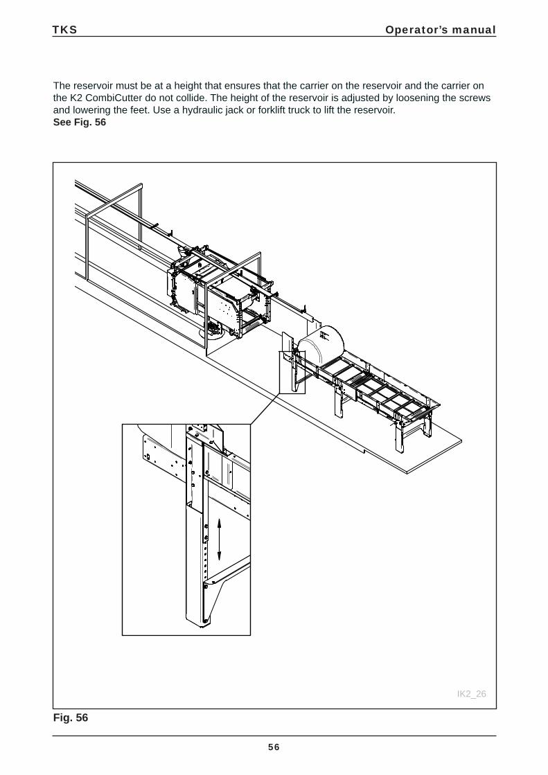
The reservoir must be at a height that ensures that the carrier on the reservoir and the carrier onthe K2 CombiCutter do not collide. The height of the reservoir is adjusted by loosening the screws and lowering the feet. Use a hydraulic jack or forklift truck to lift the reservoir. See Fig. 56
Fig. 56

TKS Operator’s manual
57
8 Use of the machineThe drum can only turn one way. Round bales can be put in whatever way you like, but we recommend putting them in so that they can rotate in the direction of the dispenser. There must not be any round bales or silage up against the drum when you start it.
Customised adjustments are the key to good results.
Check list for commissioning the machine
HIGHLY IMPORTANT! • The power supply must have a high enough
voltage during all phases, and fuses and power cables must be big enough.
• The power supply must be connected to the CombiCutters’s control panel by an authorised electrician. Adjust the overload protection relay, based on your measure-ments and the power rating of the equipment.
• Start the engine of the drum from the control panel. Check that the cutting drum is rotating in the right direction. If you need to switch the phases, you must do this on the power supply cable coming from the fuse box.
• Never start the drum’s engine when there are bales lying against the drum. Reverse the conveyor belt so that the drum is free when it is started.
• The cutter is equipped with frequency control for the speed of the conveyor belt. The conveyor belt can also be operated manually both forwards and backwards.
• If using chopped silage, the machine must not be overloaded (not above the top of the drum).
Depending on how it is used/ the type of feed, adjustments may be needed in order to customise it to your conditions.
It is very important to adjust the feed speed to local conditions, so as to avoid choking the drum.This is very important if you want to achieve good results. You will need to use trial and error here.
The speed is infi nitely adjustable using the potentiometer on the control panel.
F A B C D E
A E
B
C
F
G
H
TKS Operator’s manual
58
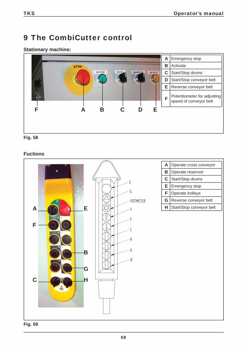
9 The CombiCutter controlStationary machine:
Fuctions
Fig. 58
Fig. 59
A Emergency stop
B Activate
C Start/Stop drums
D Start/Stop conveyor belt
E Reverse conveyor belt
F Potentiometer for adjusting speed of conveyor belt
A Operate cross conveyor
B Operate reservoir
C Start/Stop drums
E Emergency stop
F Operate trolleys
G Reverse conveyor belt
H Start/Stop conveyor belt

A B
D E F
C
C
A
IG
E
F
H
B
D
TKS Operator’s manual
59
Fig. 60
A Activation button
B Main stop switch
C Start drum
D Stop drum
E Activation function conveyer belt
F Hold function conveyer belt return
G Trolley forward
H Trolley back
I 2 x speed (Trolley)
Fig. 61
A Radio
B Off
C Manual
D Forward
E Off
F Return
10 Wireless radio I/R operation K2• When switches are in position (A) the radio will work.• Position (C) is for the manual operation of the carriages, and facilitates the use of positions (D)
and (F). See Fig. 60
To activate the radio, point the remote control at the TKS sticker on the operating panel.See Fig. 60
• Press and hold button (A) while holding the remote control 10 cm from the operating panel (TKS sticker).
• Then IR will be activated, and radio control can be used.• By pressing and holding function (I) at the same time as (G) or (H), two carriage speeds will be
activated.• If the functions have not been activated in some time, the radio must be reactivated. See Fig. 61

TKS Operator’s manual
60
10.1 I/R operation K2 for all functionsOperation of side dispenserThe side dispenser will start at the same time as the drum when switch C is pressed. The direction is random.To change the direction of the side dispenser, stop the drum by pressing switch D. The direction of the side dispenser will change when the drum is restarted.Pressing switches D and C quickly will not stop the drum.The conveyor belt must be started after the direction has changed.
• Remember to start the conveyor belt after the direction of the side dispenser has been changed.• If the drum is stopped, the side dispenser will stop when the stop switch is pressed.

TKS Operator’s manual
61
76
1 3
2
4 5
TKS Operator’s manual
62
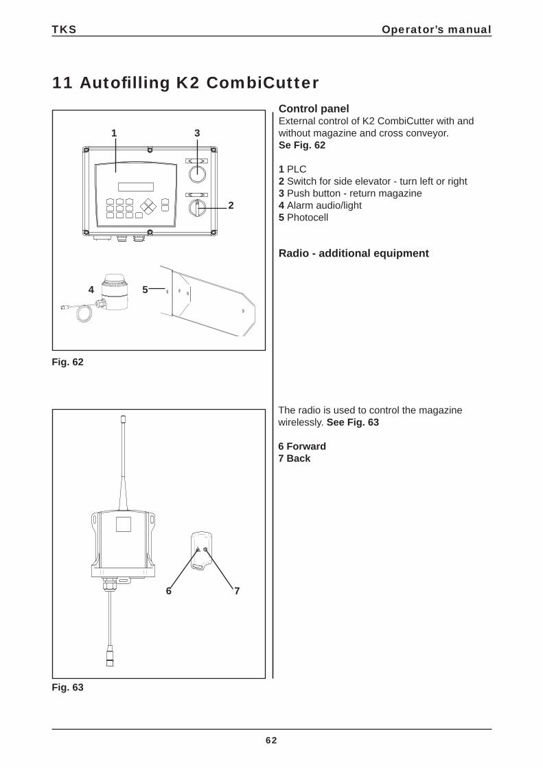
11 Autofi lling K2 CombiCutterControl panelExternal control of K2 CombiCutter with and without magazine and cross conveyor.Se Fig. 62
1 PLC 2 Switch for side elevator - turn left or right 3 Push button - return magazine4 Alarm audio/light5 Photocell
Radio - additional equipment
The radio is used to control the magazine wirelessly. See Fig. 63
6 Forward7 Back
Fig. 63
Fig. 62

TKS Operator’s manual
63
Status:Stand by – readyStart feed dispensing – feed dispensing startsFeed dispensing – feed dispensing in progressStop feed dispensing – feed dispensing stopsFilling – fi lling from tank is activated
Menu:Manual controlSettings
Manual controlKeys:1 – Drum2 – Reversal of the conveyor belt3 – Conveyor belt moves forward4 – Magazine forward5 – Cross conveyor
Settings in window 1:Start time – Start time for feed dispensing after receipt of signal.Belt start – Start time for belt after the drum has started.
Belt rwd – Time, reversal of the conveyor belt after feed dispensing has fi nished.Side el stp – Delay time for side elevator after feed dispensing has fi nished.
Fill delay – Time, fi lling delay after the photocell is active.
Fill stp d – Delay time after the photocell has operated.

B A
A B
C
D
D
F
10 s
E
3 s
TKS Operator’s manual
64
With the factory settings, the machine works as follows:If the pressure against the cutting drum becomes to high, the conveyor belt stops for 2 seconds before restarting. The speed of the conveyor belt can be adjusted (infi nitely) on the converter.If you have diffi cult feed, such as frozen round bales, it may be a good idea to reduce the speed of the conveyor belt and adjust the time relay.
A Current meter A Current meter B Frequency converter for conveyor belt C Frequency converter fl oor cart/ceiling rail operation D Location of multifunction timer F Motor protection device for cutter motor See Fig. 64
Setting for the multifunction timer must be as shown in Fig. 64, and need not normally be changed. When TIME is at 1 and RANGE is 1 s, the time delay is 1 second once overpressure against the cutter roller is reached.
12 Multi-function time relay
12.1 Frequency converter
The speed of the conveyor belt allows for infi nitely variable adjustment, in order to regulate the feed speed to the machine. Use the switch on the left-hand side of the auto control cabinet, marked F in Fig. 58, or D in Fig. 59 on machines with a remote control panel. The speed can be adjusted from 0 to 50 Hz and the value can be seen in the frequency converter display. See Fig. 65/B Current meter The pressure against the cutter roller is deter-mined by the current meter. See Fig. 65/A Strømmåler The pressure against the cutter roller is determined by the current meter. See Fig. 65/A Factory settings: 230V - 60% 400V - 35% If this is adjusted too high, the motor protection device on the cutter motor will trip.If this is adjusted too high, the motor protection device on the cutter motor will trip.
Fig. 64
Fig. 65
Rotate knob FUNCTION to Dr
Rotate knob TIME to 1
Rotate knob RANGE to 1s

A
B
TKS Operator’s manual
65
12.2 Motor protection device for cutter motorAdjustment knob for current strength. See Fig. 66/A
Check that the motor protection device has been set to the same as the A value on the motor’s rating plate (maximum of 10% above)This may vary from motor to motor.
Normal setting:5,5 kW cutter motor 230V = 21A 400V = 15A7,5kW cutter motor 230V = 27A 400V = 18A NB! Remember that the power supply network and power supply cables must be suffi ciently well dimensioned to prevent voltage drop, as the machine’s performance will deteriorate dramatically in such a situation. Use a 6 mm2 power supply cable and minimum 32 amp fuses. See also chapter 2.5: Installing the power supply.
Automatic reset of motor protection device. All buttons in the upper position. Se Fig. 67/B
Fig. 66
Fig. 67

TKS Operator’s manual
66
13 Frequency converter
The converter determines how the conveyor belt presses the feed against the drum. The converter is pre-programmed by TKS.
Fig. 68a
Omron J7
Fig. 68b
Yasakawa J1000
1 Press the blue mode button. The indicator light will move from left to right. Repeat until the red indicator comes on for PRGM. The display will show e.g. n01.
2 Press the arrow buttons up or down until you reach the required parameter, e.g. n60.
3 Press the arrow buttons up or down until you reach the required value, e.g. 80
4 Press the arrow buttons up or down until you reach the required value, e.g. 80
5 Press the yellow Enter button to save the new value. Wait a short while. The display will show n60
6 Press the blue mode button, and the green indicator light for FREF will come on.
If access is required to check the setting, this is performed in the following manner:
TKS Operator’s manual
67
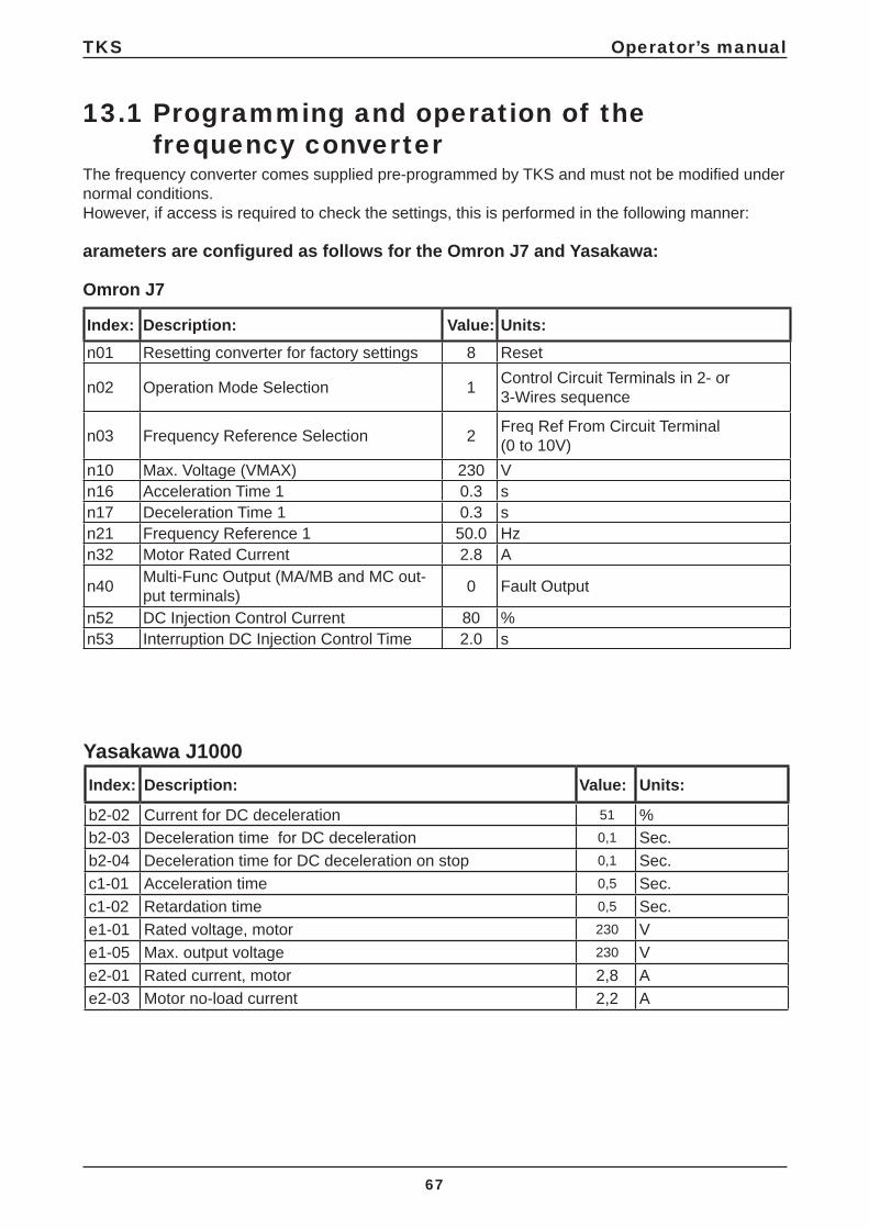
The frequency converter comes supplied pre-programmed by TKS and must not be modifi ed under normal conditions.However, if access is required to check the settings, this is performed in the following manner:
arameters are confi gured as follows for the Omron J7 and Yasakawa:
Omron J7
13.1 Programming and operation of the frequency converter
Index: Description: Value: Units:n01 Resetting converter for factory settings 8 Reset
n02 Operation Mode Selection 1 Control Circuit Terminals in 2- or 3-Wires sequence
n03 Frequency Reference Selection 2 Freq Ref From Circuit Terminal (0 to 10V)
n10 Max. Voltage (VMAX) 230 Vn16 Acceleration Time 1 0.3 sn17 Deceleration Time 1 0.3 sn21 Frequency Reference 1 50.0 Hzn32 Motor Rated Current 2.8 A
n40 Multi-Func Output (MA/MB and MC out-put terminals) 0 Fault Output
n52 DC Injection Control Current 80 %n53 Interruption DC Injection Control Time 2.0 s
Index: Description: Value: Units:
b2-02 Current for DC deceleration 51 %b2-03 Deceleration time for DC deceleration 0,1 Sec.b2-04 Deceleration time for DC deceleration on stop 0,1 Sec.c1-01 Acceleration time 0,5 Sec.c1-02 Retardation time 0,5 Sec.e1-01 Rated voltage, motor 230 Ve1-05 Max. output voltage 230 Ve2-01 Rated current, motor 2,8 Ae2-03 Motor no-load current 2,2 A
Yasakawa J1000
TKS Operator’s manual
68
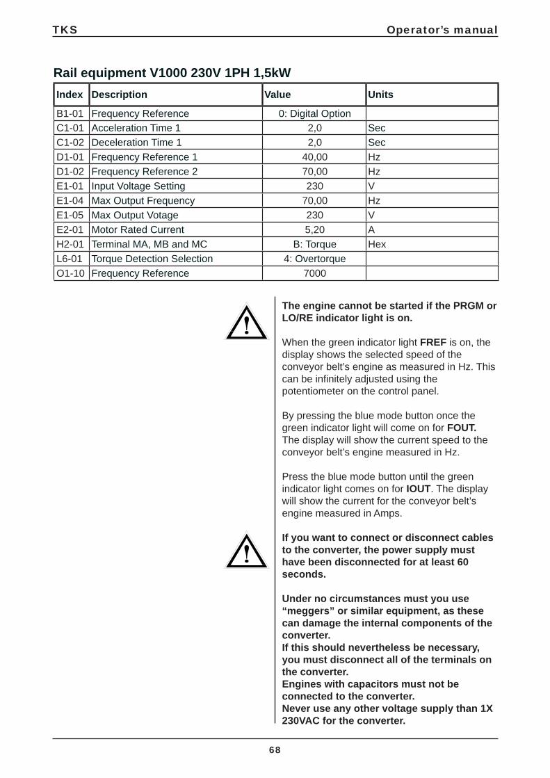
The engine cannot be started if the PRGM or LO/RE indicator light is on.
When the green indicator light FREF is on, the display shows the selected speed of the conveyor belt’s engine as measured in Hz. This can be infi nitely adjusted using the potentiometer on the control panel.
By pressing the blue mode button once the green indicator light will come on for FOUT.The display will show the current speed to the conveyor belt’s engine measured in Hz.
Press the blue mode button until the green indicator light comes on for IOUT. The display will show the current for the conveyor belt’s engine measured in Amps.
If you want to connect or disconnect cables to the converter, the power supply must have been disconnected for at least 60 seconds.
Under no circumstances must you use “meggers” or similar equipment, as these can damage the internal components of the converter. If this should nevertheless be necessary, you must disconnect all of the terminals on the converter. Engines with capacitors must not be connected to the converter. Never use any other voltage supply than 1X 230VAC for the converter.
Index Description Value Units
B1-01 Frequency Reference 0: Digital OptionC1-01 Acceleration Time 1 2,0 SecC1-02 Deceleration Time 1 2,0 SecD1-01 Frequency Reference 1 40,00 HzD1-02 Frequency Reference 2 70,00 HzE1-01 Input Voltage Setting 230 VE1-04 Max Output Frequency 70,00 HzE1-05 Max Output Votage 230 VE2-01 Motor Rated Current 5,20 AH2-01 Terminal MA, MB and MC B: Torque HexL6-01 Torque Detection Selection 4: OvertorqueO1-10 Frequency Reference 7000
Rail equipment V1000 230V 1PH 1,5kW
TKS Operator’s manual
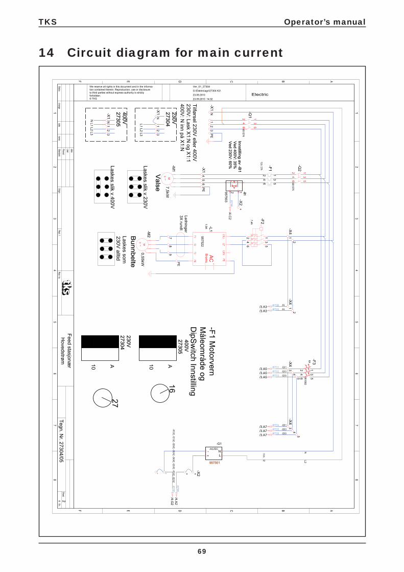
69
14 Circuit diagram for main current
TKS Operator’s manual
70
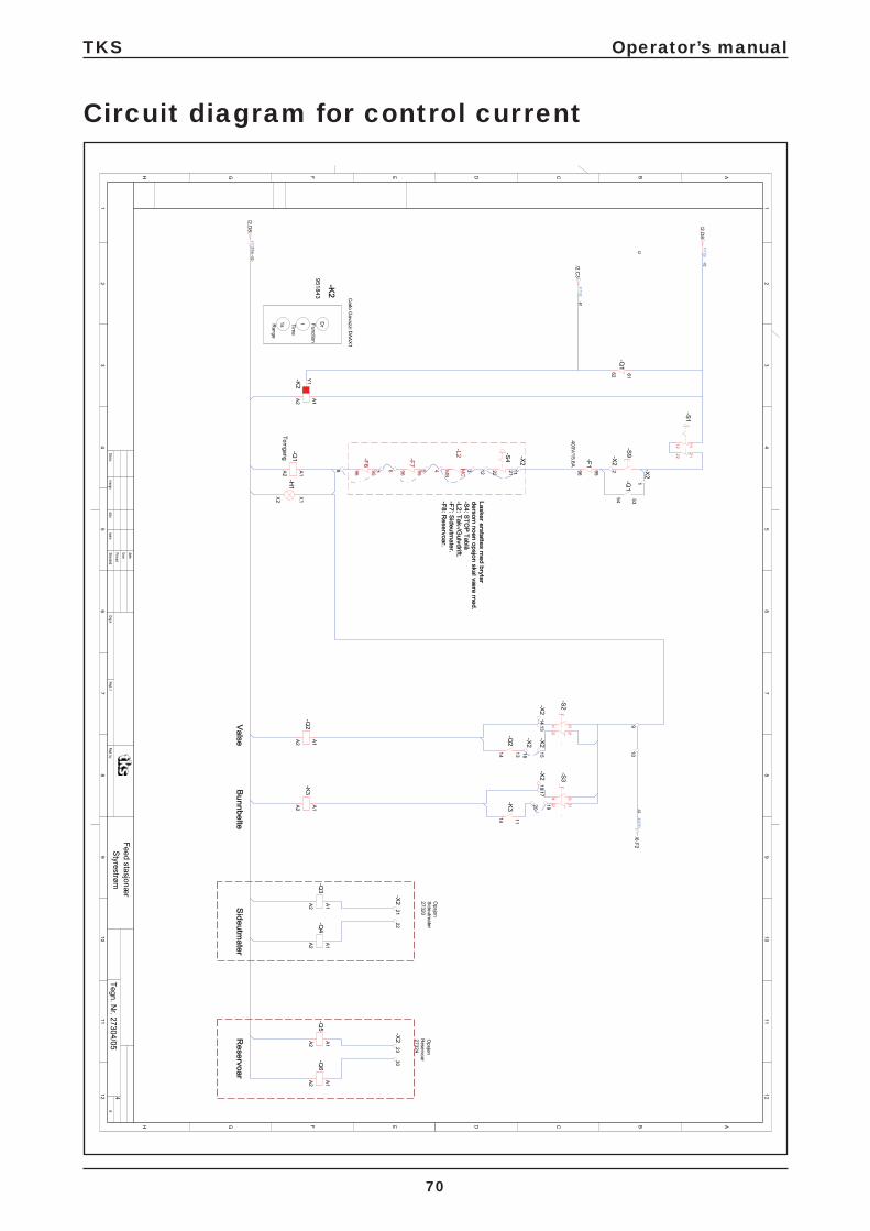
Circuit diagram for control current

TKS Operator’s manual
71
Circuit diagram for options

TKS Operator’s manual
72
Circuit diagram for frequency converter

TKS Operator’s manual
73
Circuit diagram for pendant control

TKS Operator’s manual
74
Circuit diagram wireless radio I/R operation K2
I/R re
ceiv
er
Rem
ote
cont
rol c
abin
et
EL-
Wat
ch T
KS
rece
iver
I/R
868
.0
Wire
less
radi
o I/R
ope
ratio
n 27
563

TKS Operator’s manual
75
Description of fault: Reason and corrective measure:• Cutter/ shredder drum has a
tendency to get stuck when you run the conveyor belt.
• A possible reason is that the drum is rotating in the wrong direction, which may result in feed getting stuck between the drum and the conveyor belt.
• Change the direction of the engine (it should ro-tate upwards as seen from the back).
• You can change the direction of rotation by switching 2 wires in the engine.
• Cutter/ shredder drum is unable to start with feed in the machine.
• Check that no feed is pressed against the drum. Reverse any feed clear of the drum.
• Check that the drum’s engine is correctly connected in relation to the voltage supply.
• 230V = triangular connection, and 400V = star connection
• Cutter/ shredder runs slowly, and only a small amount of feed comes out
• The knives on the drum are blunt.• Sharpen them with an angle grinder or other
suitable tool. (Do not grind the knives when they are hot, as they are factory tempered).
• The machine is overloaded and is unable to rotate the feed properly.
• Remove some of the feed to allow the drum to rotate.
• The cutter/ shredder engine is running, but the drum is not rotating.
• Check the chain and transmission on the back cover.
• NB! Remember to turn off the power supply to the machine before removing the cover.
• The cutter/ shredder drum’s engine won’t start
• Check the power supply. • The overload protection relay has been tripped. • There is a fault with the control panel or cable
(contact an electrician).
• The conveyor belt does not move forwards, but does reverse.
• Check the converter for alarms. (Cf. the separate troubleshooting guide for the converter). Check that the speed can be adjusted. (Dial on control panel, potentiometer). When the dial is turned, the value on the display of the converter should in-crease or decrease. If the display does not react, check and if necessary replace the potentiometer.
• The conveyor belt’s engine runs, but the conveyor belt does not move forwards or backwards
• There is a problem with the transmission from the chain.
• Check the chain and the transmission.
15 Troubleshooting the CombiCutterThis troubleshooting guide deals with the most likely problems that may occur with the machine.

TKS Operator’s manual
76
16 Maintenance and careNB!Always pull out the plug before inspecting, maintaining or repairing the machine.
• You should clean the conveyor belt, cogwheels, axles and bearing casings as required and at least once a year.
IMPORTANT!• Do not tighten the conveyor belt to tight or
askew. Ensure that drive chains are also kept tight. Check them regularly for slack or damage.
• Bearing journals and chains should be lubricated every 24 operating hours or at least once a month.
• Ensure that electrical equipment is not sub-jected to excessive temperature fl uctuations. This can lead to condensation and short circuits.
• The oil in the worm gears should not be exposed to temperatures below minus 30 degrees C. If the machine needs to run normally at below -30o C, contact the manufacturer for advice and guidance
• The knives on the drum are made of tempered steel with a precision engineered cutting edge. Check the edge regularly for damage or wear and tear. You can sharpen the blades while the knives are still attached to the drum. This is easy to do by dragging an angle grinder across the inside of each knife blade.

A
B
4
5
2
3
1
6
C
TKS Operator’s manual
77
Fig. 69
Lubrication
Recommended grease: Ruysdael WR2 Q8 oils Recommended oil: Shell Tivela oil
Component/ location Quantity Action Operating 1 Grease nipple - bearing operating side conveyor 1 Lubrication 10 h2 Grease nipple - bearing return side conveyor belt 1 Lubrication 10 h3 Grease nipple- bearing for drum 1 Lubrication 10 h4 Grease nipple- bearing drum 1 Lubrication 10 h5 Grease nipple - bearing conveyor belt 1 Lubrication 10 h6 Lubrication of chain 1 Lubrication 24 h
AGIP KLUBER SHELL MOBIL
Telium VSF 320 Syntheso D220 EP Tivela Oil WB Glygoil 30 SHC 630
Oil change on wormsAmmount 0,14 litre

988010
A
B
TKS Operator’s manual
78
Fig. 70
Tightening the conveyor belt
It is important to keep the conveyor belt tight. This should be checked at regular intervals. Tighten the conveyor belt by turning the adjustment screw on the back of the machine. See Fig. 70
OBS!It is important to retighten it after only 1-2 bales/ cut bales because of varnish etc. that gets rubbed off and makes the belt slack.
Remember to tighten it the same number of turns on both sides.Run the conveyor belt without any load after tightening it to check that everything is working properly.
• A Adjusting screw
NB!Bottom chain B must be tensioned until the entire bottom girder can be seen from the side.See Fig. 71
Fig. 71
Maintenance and inspection of current collectorIt is recommended that the current collector is inspected after 1 month of operation, then every 1,000 km or once a year thereafter.
• Sweep the protective membrane along the conductor rail with a brush/sponge • Inspect brushes • Remove copper strip and clean • Clean cart

A
B
TKS Operator’s manual
79
Tightening the chain of the drum and conveyor belt
Check the tightness of the drum’s chain at regular intervals and retighten the drive chain at the same time.See Fig. 72
• A Adjusting screw• B Sprocket
NB! The chains must be lubricated once a week.
Fig. 72

TKS Operator’s manual
80
Service instructions for K2 CombiCutterGeneral Safety instructions.
• Turn off main powerswitch • Disconnect main powersupply or turn off master fuse.• When working under rail-suspended machine, use safetyramp under to prevent crushing.• Do not work under unsecured machine.
Bottom belt:
• Release tension, check bearrings /plummer blocks. Change if worn
K2 – Chain wheelK2 – Drive shaftConfi guration
• 273079• 273071
(1600)• 273176
(1200)
Measure-ment A must not exceed 70 mm
• Check chain wheels. If worn (slots are more than 70mm) or damaged – change
• NB! When changing Chain wheels, also consider changing chain and chainconnectors.
Check the voltage and the voltage parameters.Replace the frequency converter.
• 273086• 265018
• Chain / Chainconnectors• Inspect for wear/damage. One can
remove max. 2 chain links on each side, before complete bottombelt must be replaced. Remove only when normal tensioning is fully
K2 – Chain 17 linksK2 – Chain 15 linksK2 – Links 20 pcs.
• 921471• 921475• 921420
• Adjustment of bottombelt. Check tracking and slack to be equal on both sides. Normal slack is when whole chain is visible under the machine.
• NB! When changing parts on bottombelt or drivechain, consider changing all related parts.
• Inspect drive-chain and chain-ensioner. The chain and chain wheel must be oiled at all times. (Saw chain oil can be used for this purpose.)
• Check chain wheel for wear.
ve-side conveyor beltK2 – Chain lock ¾”K2 – Chain ¾”K2 – Chain wheel ¾” Z 12K2 – Chain wheel ¾” Z 28
• 650004• 921577• 270456• 273237
A

TKS Operator’s manual
81
• Lubricate all bearings; ensure that the bearings receive
• lubrication. Minimum 3-4 pumps with grease gun.
• Inspect all lubrication hoses. • Replace defective/damaged lubrica-
tion points and hoses.
Recommended grease :Ruysdael WR2 Q8 or equivalent
• Change oil on gearbox at least every second year. Check regularly for leakage or extraordinary noises.Heavy use needs inspection more often.
Oil: Shell Tivela oil S – 220gearmotor valseK2 – gearmotor Bottom belt
• 3,2 liter
• 2,1 liter
Drum(Roller:)
• For inspection of drum-bearrings, use a beam to lift/bend drum. If loose or any dissonance when operated, change bearings.
• Turn cutter-drum. Inspect that knives do not touch counter-knives.
Drum-bearing • 273017
• Check V-belts. Change when worn / K2 – V-belt • 922267
• Damaged or missing knives must be replaced. All blunt knives must be grinded.
• Grinding should be done at least for every 200 bales or when needed.
K2 – blade setALWAYS enter your serial number, year of manufac-ture, and the number of knives
• 27080
• Check roller screens for damage/ wear. Make sure that there is no material/silage between the end of the roller
Innercover • 270045
Rail-suspension:
• On monorails, make sure safety-chains are mounted to prevent fall, if main suspension bolt breaks.
• Inspect chain tension and thighten if necessary (slack between 1 – 2,5 cm).
• Inspect trolleywheels and bearings. • Check width of trolleywheels
against width of I-beam (Beam +5mm max.)
K1 / K2 – chainK1 / K2 – chainlock
• 921501• 921502

TKS Operator’s manual
82
• Inspect gearbox for leakage. Check bolts and suspension
K2 – worm • 409025
• NB! The thrust bearing (swivel) of a rail must be well lubricated; also check that the suspension bolt pin is in place and well secured.
BearingPin
• 932002• 921605
• Carefully check the suspension, bolts and bearing.
• Replace these at the slightest sign of wear.
Side-conveyor:
• Remove rubberbelt. Clean drums and frame
K2 – belt L 3760 mmbelt L 2760 mmbelt L 2160 mm
• 270343• 270320• 270314
• Check bearings for slack, noise and wearing. Replace if worn.
• Gearbox is checked for leakage an noise.
K2 – worm K2 – drum returndrum drive
• 409015
• 270347• 270342
• Visual inspection of rubberbelt K24 pcs. Bearings
• 932510
• Mount rubberbelt and thigthen. Slack should be from 2 – 3 cm.
K24 pcs. rotarycups
• 270845
Electrical system:
• Check cables for breaks, pinching damage, wear, and possible chew marks from mice and rats.
• Carry out function tests on all emergency stop devices.
• Test motorprotections.• Start motors manually. Hold in the
blue button on protectionrelay until motor stops.
Conductor rail:
• Remove the current collector, clean it and replace the carbon brushes if they are worn.
• NOTE! If there is less than 2 mm to the wear mark, the carbon brushes should be replaced.

TKS Operator’s manual
83
• Check the copper strips in the con-ductor rail. If they arecorroded, you can contact TKS to hirea cleaning trolley
•
• Check heating cables/strips for function, if installed.

TKS Operator’s manual
84
17 Model description and area of use on the spreader unitThe TKS spreader unit is an alternative piece of equipment designed to spread straw, hay, paper and sawdust. It can also be used to spread other light materials.The spreader unit is fi tted to the side member under the drum at the front of the K2 CombiCutter.The spreader blades are driven by 2 motors which are mounted on the underside of the spreader unit.
The K2 CombiCutter with spreader unit is rail-mounted to the ceiling above the livestock (min. 1.5 m above ground level).The spreader unit is equipped with 2 plates on each side and these can be adjusted according to the desired spread range (2–7 m).
At the front of the robot is the conveyor belt with drum which rotates and cuts the material.The roller drum, which is driven by a worm with a motor, is fi tted above the cutter roller. This forces the excess material further down inside the drum and then out onto the spreader unit.
A back plate is fi tted to the rear of the K2 CombiCutter, the purpose of which is to keep the spreading material in place and the back plate forces the spreading material forwards.
The roller drum with blades rotates upwards and cuts the material.The machine is very quiet and, because of the large roller, the power consumption of the main motor is only 7.5 kW. The conveyor belt has its own gear motor. The speed of the K2 CombiCutter with spreader unit can be adjusted with a frequency converter. This makes the forward traction extremely fl exible.
The spreading material can be loaded on either side by moving the frames from left to right.
All functions of the machine are controlled via remote control.
PLEASE NOTE! The instructions given in this operator’s manual apply to standard operating conditions. Individual circumstances may arise at the premises of the user that deviate from the instructions provided here. Changes to the machines and equipment as a result of such circumstances shall not be grounds for making a claim against the manufacturer or supplier.
Climate, temperature, material, moisture, mown/cutting length and bale size are some factors that may affect the functionality and performance of the machine. It is important to adapt and adjust the machine to suit local conditions.This is important to achieve the best possible result.
TKS Operator’s manual
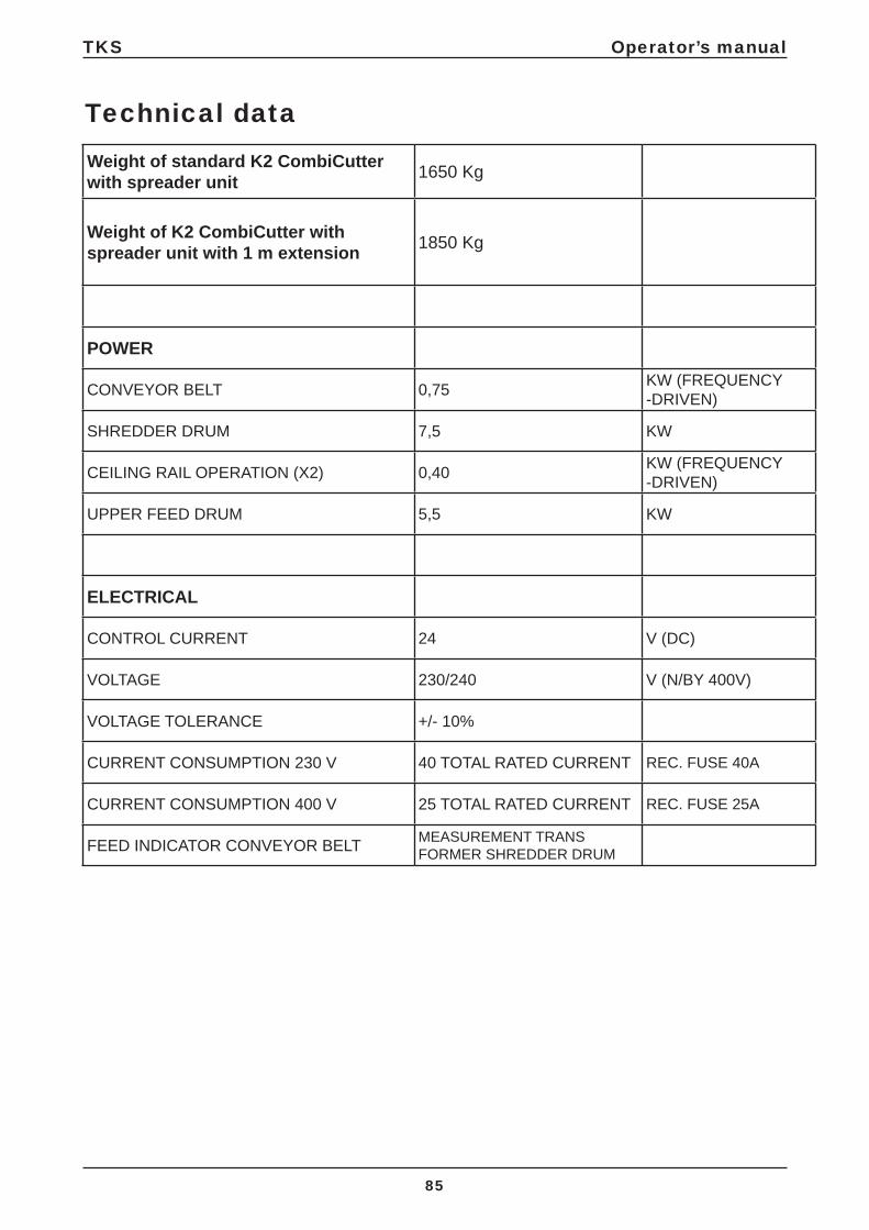
85
Technical dataWeight of standard K2 CombiCutter with spreader unit 1650 Kg
Weight of K2 CombiCutter with spreader unit with 1 m extension 1850 Kg
POWER
CONVEYOR BELT 0,75 KW (FREQUENCY -DRIVEN)
SHREDDER DRUM 7,5 KW
CEILING RAIL OPERATION (X2) 0,40 KW (FREQUENCY -DRIVEN)
UPPER FEED DRUM 5,5 KW
ELECTRICAL
CONTROL CURRENT 24 V (DC)
VOLTAGE 230/240 V (N/BY 400V)
VOLTAGE TOLERANCE +/- 10%
CURRENT CONSUMPTION 230 V 40 TOTAL RATED CURRENT REC. FUSE 40A
CURRENT CONSUMPTION 400 V 25 TOTAL RATED CURRENT REC. FUSE 25A
FEED INDICATOR CONVEYOR BELT MEASUREMENT TRANSFORMER SHREDDER DRUM

TKS Operator’s manual
86
18 Use of the machine with spreader unitThe drum can only turn one way. Round bales can be put in whatever way you like, but we recommend putting them in so that they can rotate in the direction of the dispenser. OBS! There must not be any round bales or silage up against the drum when you start it.
Customised adjustments are the key to good results.
Check list for commissioning the machinew/spreader unit
HIGHLY IMPORTANT! • The power supply must have a high enough
voltage during all phases, and fuses and power cables must be big enough.
• The power supply must be connected to the CombiCutters’s control panel by an authorised electrician. Adjust the overload protection relay, based on your measure-ments and the power rating of the equipment.
• Start the engine of the drum from the control panel. Check that the cutting drum is rotating in the right direction. If you need to switch the phases, you must do this on the power supply cable coming from the fuse box.
• Never start the drum’s engine when there are bales lying against the drum. Reverse the conveyor belt so that the drum is free when it is started.
• The cutter is equipped with frequency control for the speed of the conveyor belt. The conveyor belt can also be operated manually both forwards and backwards.
• Ensure that the end switch is connected to the operating panel. See Fig. 73
Depending on how it is used/ the type of feed, adjustments may be needed in order to customise it to your conditions.
It is very important to adjust the feed speed to local conditions, so as to avoid choking the drum.This is very important if you want to achieve good results. You will need to use trial and error here.Here it is a case of “practice makes perfect”.
Fig. 73
TKS Operator’s manual
87
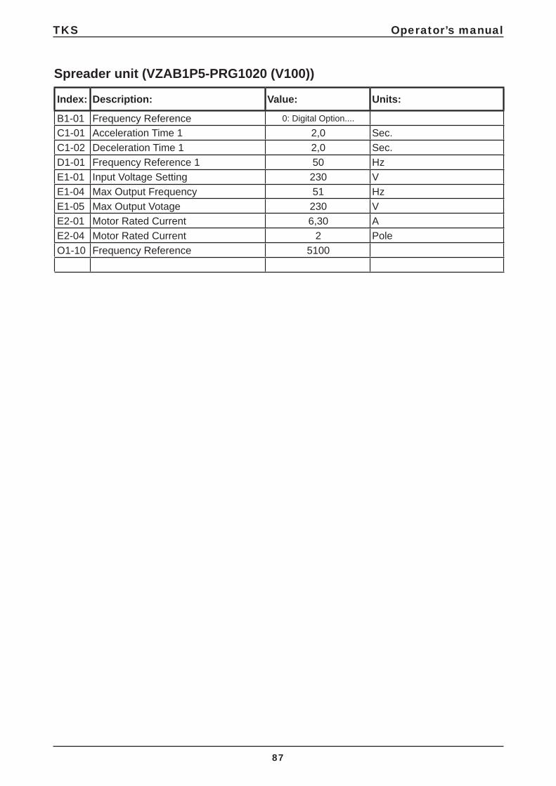
Index: Description: Value: Units:
B1-01 Frequency Reference 0: Digital Option....
C1-01 Acceleration Time 1 2,0 Sec.C1-02 Deceleration Time 1 2,0 Sec.D1-01 Frequency Reference 1 50 HzE1-01 Input Voltage Setting 230 VE1-04 Max Output Frequency 51 HzE1-05 Max Output Votage 230 VE2-01 Motor Rated Current 6,30 AE2-04 Motor Rated Current 2 PoleO1-10 Frequency Reference 5100
Spreader unit (VZAB1P5-PRG1020 (V100))

5000
6000
2440
2000
4488
1290
1800
1500
3430
3200
1250
1760
3940
1000
TKS Operator’s manual
88
19 Main measurements for machine with spreader unit• The distance from the ground to the suspended cart must be at least 1,500 mm. • Alternative round bale sizes: 1,200 – 1,500 – 1,800 mm• Max. size of square bales: 3,200x1,250 mm
All measurements are in mm
Fig. 74

5000
6000
2440
2000
2 -
7m
1500
MIN
3380
3600
A
A
B
CE
D
IKS_02
F
TKS Operator’s manual
89
20 Width adjustment on spreader unit• The spreading width can be adjusted by changing the angle of the side plates A. Once the side
plates have been adjusted, you can achieve a spreading width which can vary from 2 to 7 m. • The speed of disc B can be changed on operating panel C.• When dispensing round bales, you can also move back plate D back when 1/3 of the round bale
has been scattered. This is so that the spreading material does not collect on top of machine E.• The speed of the spreader unit is adjusted using switch F on the converter on the operating
panel.
Fig. 75

H
B
A
E D
C
G
F
1
2
32
3
TKS Operator’s manual
90
Functions
A Start roller
B START/STOP conveyor belt
C STOP all
D Roof operation – outward
E Roof operation – return
F Activated – maintain roof operation
G Conveyor belt – return
H Emergency stop
21 Remote control
Fig. 76
TKS Operator’s manual
91
22 Use of radio-controlled spreader unit
NB!• To activate radio control, release the
emergency stop and activate radio con-trol by pressing F.
• Fit end switch 1 to the traversing carriage as shown in the drawing.
• Fit resets 2 and 3 to the rail at each end of the track.
• For automatic roof operation, hold in E or D (outward – return) and F (Activated – maintain roof operation) simultaneously. Switch off automatic operation by pressing C. The carriage will stop automatically when it reaches a reset.
• Press A to start the spreader unit and roller, followed by B (START/STOP conveyor belt). For automatic operation of the machine, hold in E or D (outward – return) and F (Activated – maintain roof operation) simultaneously.
The machine will then start to spread automatically until it reaches the next reset. The machine will then stop. Press C to switch off automatic operation.
If the emergency stop has been used, press F to restart the machine (a green light is then displayed on the pendant control).
The spreader unit can be operated manually:• Press A to start the spreader unit and roller.• Press B to start/stop the conveyor belt.• Press E or D for roof operation.• Press C to stop the machine.
See Fig. 76

TKS Operator’s manual
92
23 Maintenance and care
NB!Always pull out the plug before inspecting, maintaining or repairing the machine.
• Remove any remaining material from the conveyor belt and spreader unit daily. This can also be removed using compressed air.
• Check that all the blades of the drum are in place. If any blades should be missing, you must replace these with new ones. This is to prevent the spreading material from entering the drum.
• Clean the conveyor belt, chain wheels, shafts and bearing shields as and when necessary and at least once a week.
IMPORTANT!• When tightening the conveyor belt, it is
important that it is not pulled too tight or crooked.Ensure that the drive chains also remain tight. Check these regularly for slackness and damage.
• Bearing journals and chains should be lubricated every 24 operating hours or at least once a month.
• Ensure that electrical equipment is not subjected to excessive temperature fl uctuations. This can lead to condensation and short circuits.
• The oil in the worm gears should not be exposed to temperatures below minus 30 degrees C. If the machine needs to run normally at below -30o C, contact the manufacturer for advice and guidance
• The drum blades are made from hardened special steel and have precision-milled cutting edges. Check the edges regularly for damage and wear and tear. The blades must be detached before sharpening. This is easily performed with an angle grinder by drawing it across the inside of each blade edge.
• NB! Keep the machine clean of dust as this constitutes a fi re hazard. It is important to clean the machine’s drums, spreading discs, conveyor belt and rear shields once a week. TKS recommends cleaning with pressurised air rather than using a high pressure washer.

TKS Operator’s manual
93
24 Circuit diagram for main current

TKS Operator’s manual
94
Circuit diagram for control current

TKS Operator’s manual
95
Circuit diagram for frequency converter

TKS Operator’s manual
96
Circuit diagram for relay replaces

TKS Operator’s manual
97
24.1 Circuit diagram for spreader unit

TKS Operator’s manual
98
24.2 Circuit diagram for K2 CombiCutter autofi lling

TKS Operator’s manual
99
Circuit diagram for K2 CombiCutter autofi lling

TKS Operator’s manual
100
Circuit diagram for K2 CombiCutter autofi lling

TKS Operator’s manual
101
Recycling- waste to resource -
TKS’s products rely on electrical and electronic components in order to work. These fall under the generic term of EE products. TKS’s products use typical components such as cables, switches, motors, control units, etc.
When TKS products are thrown away those components containing contaminants should be treated and sorted in such a way that they do not pollute the environment. Contaminants should be taken care of safely.
Distributors are obliged to accept EE waste from products in the range of goods they sell. This waste should be kept safe and sent on to an approved waste recipient or treatment plant.EE waste must be sorted and transported in such a way that it is not damaged or destroyed.
If you need further information on the treatment of EE waste, please contact your distributor.
RegardsTKS AS

TKS Operator’s manual
102

TKS Operator’s manual
103
Notes

www.tks-as.no
T. Kverneland & Sønner AS,Kvernelandsvegen 100N-4355 KvernalandNorway e-post : [email protected] +47 51 77 05 00Fax +47 51 48 72 28
TKS is a family owned company with a strong brand name.We are providing our customers with a unique and complete range of high quality products.
TKS Operator’s manual
104