operator’s manual - hwei teh operators manual d12 m… · welcome aboard volvo penta marine...
TRANSCRIPT

OPERATOR’S MANUALD12

CALIFORNIA
Proposition 65 Warning
Diesel engine exhaust and some of its constituents are knownto the State of California to cause cancer, birth defects, andother reproductive harm.
This operator’s manual is also available in the following languages:
Diese Betriebsanleitung ist auch auf Deutsch erhältlich.Ein Bestellcoupon ist am Ende der Be-triebsanleitung zu finden.
Ce manuel d’instructions peut être commandé en français.Vous trouverez un bon de commande à la fin du manuel d’instructions.
Este libro de instrucciones puede soli-citarse en español.El cupón de pedido se encuentra al final del libro.
Den här instruktionsboken kan bestäl-las på svenska.Beställningskupong finns i slutet av instrukti-onsboken.
Questo manuale d’istruzioni può esse-re ordinato in lingua italiana.Il tagliando per l’ordinazione è riportato alla fine del manuale.
Dit instructieboek kan worden besteld in het Nederlands.De bestelcoupon vindt u achter in het instruc-tieboek
Denne instruktionsbog kan bestilles på dansk.Bestillingskupon findes i slutningen af instruk-tionsbogen.
Tämän ohjekirjan voi tilata myös suo-menkielisenä.Tilauskuponki on ohjekirjan lopussa.
Este manual de instruções pode ser encomendado em português.O talão de requerimento encontra-se no fim do manual.
Áõôü ôï åã÷åéñßäéï ÷ñÞóçò äéáôßèåôáé óôçí áããëéêÞ ãëþóóá.Ãéá íá ðáñáããåßëåôå Ýíá áíôßôõðï, óõìðëçñþóôå ôç öüñìá ðïõ âñßóêåôáé óôï ôÝëïò áõôïý ôïõ åã÷åéñéäßïõ ÷ñÞóçò.
Данное руководство оператора имеется на русском языках.Для получения инструкции на нужном языке заполните форму в конце инструкции.
Bu kullanýcý el kitabý Türkçe diller-inde mevcuttur.Birnüshasýný sipariþ etmek için kullanýcý el kitabýnýn sonundaki formu doldurun.

Welcome aboardVolvo Penta marine engines are used all over the world. They are used in all possible operating conditions for professional as well as leisure purposes. That’s not surprising.
After 100 years as an engine manufacturer the Volvo Penta name has become a symbol of reli-ability, technical innovation, top of the range performance and long service life. We also believe that this is what you demand and expect of your Volvo Penta engine.
We would like you to read this operator’s manual thoroughly and consider the advice we give on operation and maintenance before your maiden voyage so that you will be ensured of fulfilling your expectations. Please pay attention to the safety instructions contained in the manual.
As owner of a Volvo Penta marine engine, we would also like to welcome you to a worldwide network of dealers and service workshops to assist you with technical advice, service require-ments and replacement parts. Please contact your nearest authorized Volvo Penta dealer for assistance.
We also invite you to visit our home page on the Internet at www.volvopenta.com
With warm regards
AB VOLVO PENTA

�
© �006 AB VOLVO PENTAWe reserve the right to make modifications without prior notice. Printed on environmentally compatible paper.
(Cover: Department of transport (shipping), license 9809095)
Contents
Stopping the engine ........................................... 50 Stop ..................................................................... 50 Cold weather precautions .................................... 51 Laying up ............................................................. 51
Maintenance schedule ....................................... 5�
Maintenance ........................................................ 54 Engine, general ................................................... 54 Lubrication system .............................................. 57 Freshwater system .............................................. 61 Seawater system ................................................. 66 Fuel system ......................................................... 70 Electrical system ................................................. 76 Reverse gear ....................................................... 81 Accessoties ......................................................... 83
Laying up/Launching ......................................... 84 Inhibiting .............................................................. 84 Bringing out of storage ........................................ 85
In case of emergency ......................................... 86 Starting with auxiliary batteries ........................... 86 Emergency shifting .............................................. 87 Fault-tracing ......................................................... 88 Diagnostic function .............................................. 89
Fault register ....................................................... 9�
Technical data ..................................................... 100 Engine ................................................................. 100 Reverse gear ....................................................... 10�
Safety information .............................................. 3 General information ............................................ 3 Boat trips ............................................................. 4 Care and maintenance ........................................ 6
Introduction ......................................................... 8 Running in ........................................................... 8 Fuel and oils ........................................................ 8 Certified engines ................................................. 9 Warranty information ........................................... 9 Identification number .......................................... 10
Presentation ........................................................ 11 Technical description ........................................... 11 Orientation ........................................................... 1�
Instruments ......................................................... 13 Instruments .......................................................... 13 Ignition lock .......................................................... 13 Start/stop panel ................................................... 13 Alarm display (optional extra) .............................. 14 EVC control panel................................................ 17 EVC system tachometer ...................................... 18 EVC system display (optional extra) .................... �7
Controls ............................................................... 35 Single lever control .............................................. 35 Two lever control .................................................. 37
Starting the engine ............................................. 38 Before starting ..................................................... 38 General information about starting ...................... 38 Starting method ................................................... 39
Operation ............................................................. 41 Reading instruments ........................................... 41 Alarm ................................................................... 4� Cruising speed .................................................... 4� Synchronising engine speed ............................... 43 Changing the helm station ................................... 43 Operation ............................................................. 45 Low speed ........................................................... 46 Trolling ................................................................. 47 Propeller shaft brake ........................................... 48 Extra equipment .................................................. 49

3
Safety informationRead this chapter very carefully. It has to do with your safety. This describes how safety information is presented in the instruction book and on the product. It also gives you an introduction to the basic safety rules for using and looking after the engine.
Check that you heave received the correct instruction book before you read on. If not, please contact your Volvo Penta dealer.
Incorrect operation can lead to personal injury and damage to products or property. So read the instruction book through very carefully before you start the engine or do any maintenance or service work. If there is still something which is unclear or if you feel un-sure about it, please contact your Volvo Penta dealer for assistance.
This symbol is used in the instruction book and on the product, to call your attention to the fact that this is safety information. Always read such information very carefully.
Safety texts in the instruction book have the following order of priority:
WARNING! Warns for the risk of personal injury, major damage to product or property, or serious malfunctions if the instruction is ignored.
IMPORTANT! Is used to call attention to things which could cause damage or malfunctions to product or property.
NOTE! Is used to call attention to important information, to facilitate work processes or operation.
This symbol is used on our products in some cases and refers to important information in the instruction book. Make sure that warning and information symbols on the engine are clearly visible and legible. Replace symbols which have been damaged or painted over.

4
Safety information
Safety advice for boat operation
Your new boatRead the instruction books and other information carefully, which came with your new boat. Learn to handle the engine, controls and other equipment in a safe and correct manner.
If this is your first boat, or a type of boat you are not experienced in using, we recommend that you practi-ce operating the boat in peace and quiet. Get to know the way the boat reacts to sea and to the controls under different speed, sea and loading conditions be-fore you cast off for your first “real” maiden voyage.
Remember that the captain of every boat is required by law to know and to observe applicable rules for traffic and safety at sea. Get to know the rules which apply to you and your waters, by contacting the rele-vant authority or sea safety organisation.
It is a good idea to go on some kind of boat operation course. We recommend that you contact a regional boat or sea safety organisation to find a suitable course.
Accidents and near missesLife saving statistics show that inadequate care of boats and engines, and deficiencies in safety equip-ment are frequent causes of accidents and near misses at sea.
Make sure that your boat and engine are maintained in accordance with the advice in each instruction book, and that the necessary safety equipment is on board, and is in working condition.
Daily checksMake it a habit to give the engine and engine bay a visual check before driving (before starting the engine) and after operation (when you have stop-ped the engine). This helps you to quickly discover whether any leakage of fuel, coolant, oil or any other abnormal event has happened, or is about to happen.
ManoeuvringAvoid sudden or surprising rudder movements and gear shifting. There is a risk that passengers could fall over, or overboard.
A rotating propeller can cause severe injury. Check that there is nobody in the water before you engage forward / astern (reverse) drive. Never drive close to bathers or in areas where you could reasonably ex-pect that people could be in the water.
Fuel fillingThere is always a risk of fire and explosion during fuel filling. Smoking is not permissible, and the engi-ne should be stopped.
Never over-fill the tank.
Shut the tank cap securely. Only use the fuel recom-mended in the instruction book. The wrong grade of fuel can cause malfunctions or stop the engine. In a diesel engine, it can also cause the regulation rod to bind and the engine will over-rev, entailing a strong risk of personal injury and machinery damage.
Do not start the engine.Do not start the engine if you suspect a fuel or LPG leak in the boat, close to explosive media, or if there is a spillage of explosive media. An explosive envi-ronment entails a risk of fire and/or explosion.

5
Safety information
Carbon monoxide poisoningWhen a boat moves forwards, an area of low pres-sure air forms behind the boat. In adverse conditions, this low pressure can be so strong that the boat’s own exhaust fumes are sucked into the cockpit or cabin, which entails a risk of carbon monoxide poiso-ning for all aboard.
The problem of low-pressure suction is worst in high, wide boats with a square transom. But even in other types of boats, low-pressure suction can be a pro-blem in some conditions, such as if you drive with the hood up. Other factors which increase the low-pres-sure effect are wind conditions, load distribution, pit-ching, trimming, open windows and ventilators etc.
Most modern boats are designed so that the problem of low-pressure suction is very rare, however. If low-pressure suction does occur anyway, do not open hatches or ventilators in the forward part of the boat. Strangely enough, this makes the problem worse. Try changing speed, trimming or load distribution instead. Also try taking down/opening the hood or modifying it in some other manner. Ask your boat dealer for ad-vice about the best solution for your particular boat.
Remember● Safety equipment: Life jackets for everybody aboard, communication equipment, emergency
rockets, approved fire extinguisher, first aid kit, life buoy, anchor, paddle, torches etc.
● Spare parts and tools: Impeller, fuel filters, fuses, tape, hose clamps, engine oil, propeller and tools for the jobs you could be expected to have to do.
● Take your chart out and study your planned route. Calculate distance and fuel consumption. Listen to weather reports.
● Tell your friends/relatives about route plans if you undertake a long journey. Remember to notify changed plans or delays.
● Inform everybody aboard about where the safety equipment is located, and how it works. Make sure that there is more than one person aboard who can start and operate the boat safely.
This list can be extended, since the need for safety equipment varies with the type of boat, and where or how it is used etc. We recommend that you ask a regional boat or sea safety organisation for more detailed maritime safety information.

6
Safety information
Safety advice for care and maintenance work
PreparationsKnowledgeThe Instruction Book contains instructions for doing the most common service and maintenance tasks in a safe and correct manner. Read them carefully be-fore starting work.
Literature for more major tasks is available from your Volvo Penta dealer.
Never do a job if you are not entirely sure about how to do it. Contact a Volvo Penta dealer for assistance ins-tead.
Stop the engine.Stop the engine before opening or removing the engine hatch/hood. Care and maintenance work should be done with the engine stopped unless otherwise speci-fied.
Prevent the engine from being started by cutting the current with the battery isolator, or remove the cable from the battery positive pole before you start service work. Fix a notice by the helmsman’s seat to say that work is in progress.
Working with, or going close to a running engine is a safety risk. Loose clothes, long hair, fingers or dropped tools can catch on rotating components and cause severe injury. Volvo Penta recommends that all service work which requires the engine to be running should be done by a Volvo Penta authorised work-shop.
Lifting the engineThe existing lugs on the engine (or reverse gear) should be used for lifting. Always check that the lifting devices are in good condition and that they have the correct capacity for the lift (engine weight together with reverse gear and auxiliaries, if fitted). The engine should be lifted with an adjustable lifting boom for safe handling. All chains or cables should be parallel to each other and should be as square as possible to the top of the engine. Please note that auxiliary equipment installed on the engine could change its centre of gravity. Special lifting devices may then be needed to obtain the correct balance and safe handling. Never do any work on an engine which just hangs from a lifting device.
Before startingRe-install all guards which have been removed during service work, before re-starting the engine. Make sure that there are no tools or other objects left behind on the engine.
Never start a turbocharged engine without the air filter in place. The rotating compressor turbine in the turbocharger can cause severe injury. There is also a risk that foreign bodies could be sucked in and cause machinery damage.
Fire and explosionFuel and lubrication oilAll fuel, most lubricants and many chemicals are flammable. Always read and observe the advice on the packages.
Work on the fuel system must be done with the eng-ine cold. Fuel leakage and spills on hot surfaces or electrical components can cause fires.
Store oil and fuel soaked rags and other flammable material in a fire-proof manner. Oil soaked rags can self-ignite in certain circumstances.
Never smoke when filling fuel, lubrication oil or close to fuel filling stations or the engine bay.
Non-original spare partsComponents in fuel systems and electrical systems on Volvo Penta engines are designed and manufactu-red to minimise the risk of explosions and fire, in ac-cordance with applicable legal requirements.
The use of non-original spare parts can cause a fire.
BatteriesBatteries contain and give off an explosive gas, espe-cially when charged. This gas is very flammable and highly explosive.
Smoking, open flames or sparks must never occur in or near to batteries or the battery locker.
Incorrect connection of a battery cable or start cable can cause a spark which can be sufficient, in its turn, to make the battery explode.
Start sprayNever use start spray or similar products as a star-ting aid. Explosions could occur in the inlet manifold. Danger of personal injury.

7
Safety information
Hot surfaces and fluidsA hot engine always offers the risk of burns. Be on your guard against hot surfaces, such as the ex-haust manifold, turbocharger, sump, charge air pipe, starting heater, hot coolant and hot lubricating oil in pipes and hoses.
Carbon monoxide poisoningOnly start the engine in a well-ventilated area. When operated in a confined space, exhaust fumes and crankcase gases must be ventilated.
ChemicalsMost chemicals, such as glycol, rust preventer, con-servation oils, degreasers etc. are hazardous. Always read and observe the advice on the packages.
Some chemicals, such as conservation oils, are flam-mable and also hazardous to breathe. Ensure good ventilation and use a protective mask for spraying. Al-ways read and observe the advice on the packages.
Store chemicals and other hazardous material out of the reach of children. Hand in surplus or used chemi-cals to a recycling station for destruction.
Cooling systemThere is always a risk of water entry when any work is done on the seawater system. For this reason, stop the engine and close the sea cocks before you start work.
Avoid opening the coolant filling cap when the engine is hot. Steam or hot coolant can spray out and cause scalding.
If the filler cap, coolant hose etc., still has to be ope-ned or removed when the engine is hot, undo the filler cap slowly and carefully, to let the pressure out before removing the filler cap completely and starting work. Note that the coolant can still be hot and cause scalding.
Lubrication systemHot oil can cause burns. Avoid skin contact with hot oil. Make sure that the oil system is de-pressurised before starting work. Never start or run the engine with the oil filler cap removed, because of the risk of oil spil-lage.
Fuel systemAlways protect your hands when searching for leaks. Fluids which leak under pressure can force their way into body tissue and cause severe injury. Risk of blood poisoning (septicaemia).
Always cover the alternator if it is located beneath the fuel filters. Fuel spillage can damage the alternator.
Electrical systemCut the currentBefore any work is done on the electrical system, the engine must be stopped and the current cut by switching off the battery isolator. Shore current for engine heaters, battery chargers or other auxiliary equipment connected to the engine must be discon-nected.
BatteriesBatteries contain a highly corrosive electrolyte. Pro-tect your eyes, skin and clothes during charging and other handling of batteries. Always use protective goggles and gloves. If this comes into contact with your skin, wash at once with soap and a lot of water. If you get battery acid in your eyes, flush at once with
8
IntroductionThis instruction book has been prepared to give you the greatest possible benefit from your Volvo Penta marine engine. It contains the information you need to be able to operate and maintain the engine safely and correctly. Please read the instruction book carefully and learn to handle the engine, controls and other equipment in a safe manner before you cast off on your maiden voyage.
Always have the instruction book available. Store it safely and do not forget to hand it over to the next owner if you sell your boat.
Environmental careAll of us want to live in a clean, healthy environment. Where we can breathe clean air, see healthy trees, have clean water in lakes and seas, and be able to enjoy the sunlight without fearing for our health. Un-fortunately, this is not self-evident these days, it is something all of us must work hard for.
As a manufacturer of marine engines, Volvo Penta has particular responsibility and for this reason, en-vironmental care is a core value in our product deve-lopment. Volvo Penta has a wide engine programme these days, where considerable progress has been made in reducing exhaust fumes, fuel consumption, engine noise etc.
We hope that you will be want to preserve these values. Always observe the advice in the instruction book about fuel grades, operation and maintenance, to avoid unnecessary environmental impact. Please contact your Volvo Penta dealer if you notice any changes such as increased fuel consumption or in-creased exhaust smoke.
Moderate your speed and distance so that wake and noise do not disturb or damage animal life, moored boats, jetties etc. Leave the archipelago and harbours in the same state you would like to find them. Re-member to always hand in drained oil, coolant, paint and wash residue, used batteries etc. for destruction at a recycling station.
If we all pull together, we can make a valuable contri-bution to the environment together.
Higher oil consumption is normal during the running in period. For this reason, check the oil level more frequently than normally recommended.
After the first period of operation, the specified war-ranty inspection “First service inspection” can be done. For more information: Please refer to the War-ranty and Service book.
Fuel and oilsOnly use the fuels and oils recommended in the in-struction book. Other grades can cause malfunctions, increased fuel consumption and eventually even shorten the life of the engine.
Always change the oil, oil filter and fuel filter at the specified intervals.
Running inThe engine must be “run in” during its first 10 hours, as follows:
Use the engine in normal operation. Full load should only be applied for short periods. Never run the engine for a long period of time at constant speed during this period.
Service and spare partsVolvo Penta marine engines are designed for high reliability and long life. They are built to withstand a marine environment, but also to have the smal-lest possible environmental impact. Through regular service and use of Volvo Penta original spare parts, these qualities are retained.
Volvo Penta’s world-wide network of authorised dea-lers is at your service. They are Volvo Penta product specialists, and have the accessories, original spa-res, test equipment and special tools needed for high quality service and repair work.
Always observe the maintenance intervals in the instruction book, and remember to note the engine/transmission identification number when you order service and spare parts.

9
Introduction
Certified enginesIf you own or operate an emission certified engine it is important to be aware of the following:
Certification means that an engine type has been checked and approved by the relevant authority. The engine manufacturer guarantees that all engines made of the same type are equivalent to the certified engine.
This makes special demands on the care and maintenance you give your engine, as follows:
● Maintenance and service intervals recommended by Volvo Penta must be complied with.
● Only Volvo Penta original spares may be used.
● Service on injection pumps, pump settings and injectors must always be done by an authorised Volvo Penta workshop.
● The engine must not be converted or modified, except for the accessories and service kits which Volvo Penta has approved for the engine.
● Installation changes to the exhaust pipe and engi-ne air inlet ducts must not be done.
● No seals may be broken by unauthorised personnel.
The general advice in the instruction book about ope-ration, care and maintenance apply.
IMPORTANT! Late or inadequate maintenance/service or the use of spare parts not approved by Volvo Penta will invalidate AB Volvo Penta’s responsibility for the engine specification being in accordance with the certificated variant.
Volvo Penta accepts no responsibility or liabi-lity for any damage or costs arising due to the above.
WarrantyYour new Volvo Penta marine engine is covered by a limited warranty, under the conditions and instruc-tions compiled in the Warranty and Service book.
Please note that AB Volvo Penta’s liability is limited to the specification in the Warranty and Service book. Read it carefully, as soon as possible after delivery. It includes important information about war-ranty cards, service, maintenance, which it is the responsibility of the owner to know, check and carry out. If this is not done, AB Volvo Penta may fully or partly refuse to honour its warranty undertakings.
Please contact your Volvo Penta dealer if you have not received a Warranty and Service book, or a customer copy of the warranty card.

10
Introduction
Identification numbersThere are type plates on the engine and transmission, marked with identification numbers. This information must always be used a reference when service and spare parts are ordered. You will probably find similar plates on your boat and its equipment. Note this information below, make a copy of the page and store it in a safe place, so that you can have the information available if the boat is stolen.
The appearance and location of the type plates is shown below. The figures in brackets refer to the location of the identification number on the type plate.
EngineProduct designation (1) D12D-C MHSerial and base engine number (�) .................................................................................
Product number (3) ..........................................................................................................
Control unit“Dataset” (parameter file) (4) ...........................................................................................
Main software (5) .............................................................................................................
Certification, IMO
Reverse gearProduct designation (6) ..................................................................................................
Serial number (7) .............................................................................................................
Product number (8) ..........................................................................................................
Reverse gear plate
Engine plate
Warranty decal
Decal, control unit
6, 7, 8
THIS ENGINE TYPE IS CERTIFIED
ACC. TO IMO NOx TECHNICAL
CODE ANNEX VI
Certification decal
D12D-C MHRATED POWER: xxx kW
RATED SPEED: xxxx RPM
MSW: xxxxxxx (5)
DST 1: xxxxxxxx (4)
DST �: xxxxxxxx (4)
SPEC. NO: xxxxxx (3)
11
PresentationThe D1�D-C MH is an in-line, direct injection 6-cylinder marine diesel engine.
The engine has electronically controlled fuel injection, a turbocharger, aftercooler, heat exchanger and thermo-statically controlled freshwater cooling, electronically controlled engine speed control and shifting.
The exhaust manifold and turbocharger are freshwater cooled to reduce heat radiation to the engine room
Technical description
Engine and cylinder block– The cylinder block and cylinder head are manu-
factured of alloyed cast iron
– Induction hardened crankshaft journalled in seven main bearings
– Replaceable wet cylinder liners
– Gallery oil cooled cast aluminium pistons
– Three piston rings, including a “keystone” type top ring
– Induction hardened overhead camshaft with roller rocker arms
– Four valves per cylinder
– Replaceable valve seats and valve guides
Fuel system – Microprocessor based fuel supply control unit
– Gear driven fuel feed pump
– Centrally located unit injectors with electromag-netically controlled fuel valves
– Spin-on fine fuel filter with water trap
Lubrication system – Freshwater cooled oil cooler
– Gear driven oil pump
– Side mounted or rear mounted full flow and by-pass oil filters of spin-on type
Turbocharging system– Turbocharger with freshwater cooled turbine hous-
ing
Cooling system– Tube heat exchanger ( or 1- circuit keel cooling)
with expansion tank
– Plate type freshwater cooled aftercooler
– Gear driven seawater pump
Electrical system – �4V electrical system, alternator (60A) with
charge sensor
– Engine mounted emergency stop button
– Power modul

1�
Presentation
D12D-C MH
1. Alternator �. Expansion tank 3. Level glass, coolant 4. Coolant filler cap 5. Charge air cooler (located beneath
cover) 6. Air filter 7. Oil cooler, reverse gear 8. Crankcase breather filters 9. Heat exchanger 10. Control unit (located behind heat
exchanger) 11. Seawater pump
D12D-C MH
1. Exhaust pipe, dry �. Turbocharger 3. Fine fuel filter with water trap 4. Emergency stop button 5. Oil filler cap 6. Coolant pump 7. Oil sump 8. Oil cooler, engine (loc. in engine
block) 9. Lubrication oil filter 10. By-pass filter for lubrication oil 11. Coolant filter 1�. Oil dipstick, engine 13. Oil filler cap 14. Oil drain pump (optional) 15. Starter motor 16. Reverse gear Twin Disk MG5114 DC
1 2 3 4 5 6 7
891011
1 2 3 4 5
67910
1112
13151614
8
13
InstrumentsThis chapter describes the instrument and control panels sold by Volvo Penta for your engine.
If you want to supplement the instrumentation, or if your boat is equipped with instruments not described here, or you are not sure about their function, please contact your Volvo Penta dealer.
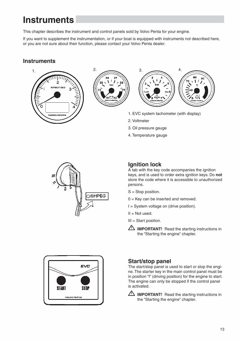
1. EVC system tachometer (with display)
�. Voltmeter
3. Oil pressure gauge
4. Temperature gauge
Ignition lockA tab with the key code accompanies the ignition keys, and is used to order extra ignition keys. Do not store the code where it is accessible to unauthorized persons.
S = Stop position.
0 = Key can be inserted and removed.
I = System voltage on (drive position).
II = Not used.
III = Start position.
IMPORTANT! Read the starting instructions in the “Starting the engine” chapter.
�. 3. 4.1.
Instruments
Start/stop panelThe start/stop panel is used to start or stop the engi-ne. The starter key in the main control panel must be in position “I” (driving position) for the engine to start. The engine can only be stopped if the control panel is activated.
IMPORTANT! Read the starting instructions in the “Starting the engine” chapter.

14
Instruments
Alarm display (optional extra) The following warning lamps should never light up during operation. On the other hand, the warning lamps light up when the starter key is first turned to the drive position. Check that all lamps function. When the engine has started, all lamps should have gone out. The lamps flash if the diagnostic function has registered malfunction. When the fault has been acknowledged, the lamp gives continuous light.
NOTE! Warning lamps should never light up during operation
Oil pressure (red indication) If the oil pressure lamp lights up during operation, the oil pressure in the engine is too low. Stop the engine at once.
Check the oil level in the engine. Please refer to “Maintenance: Lubrication” to check and top the oil up.
Also check that the oil filters are not blocked. Please refer to “Maintenance: Lubrication system”
Please refer to the “If something happens” chapter, and you will find detailed information about recom-mended action in the “Diagnostic function” section.
WARNING! Continued operation when the oil pressure is too low can cause serious engine damage.
Water in fuel filter (orange indication) If the lamp lights up, there is too much water in the water trap in the fuel filters.
Empty the water trap underneath the secondary fuel filter. Please refer to “Maintenance: Fuel sys-tem”.
Please refer to the “In case of emergency” chapter, and you will find detailed information about recom-mended action in the “Diagnostic function” section.

15
Instruments
Battery (orange indication) The battery lamp lights up if the alternator is not charging. Stop the engine if this lamp lights up during operation. If the lamp lights up, this can be due to a fault in the electrical system or because the alterna-tor drive belt is slack.
Check the alternator drive belts. Please refer to “Maintenance: Engine, general”.
Also check that there is no poor contact/broken wires.
Please refer to the “If something happens” chapter, and you will find detailed information about recom-mended action in the “Diagnostic function” section.
WARNING! Do not continue operation if there is any problem with the alternator drive belts. This could cause serious engine damage.
Coolant temperature (red indication) The coolant temperature lamp lights up when the coolant temperature is too high. Stop the engine if this lamp lights up during operation.
Check the coolant level. Please refer to “Mainte-nance: Fresh water system”.
Check that the sea water filter is not blocked. Please refer to “Maintenance: Sea water system”
Also check the impeller in the sea water pump. Please refer to “Maintenance: Sea water system”.
Please refer to the “If something happens” chapter, and you will find detailed information about recom-mended action in the “Diagnostic function” section.
WARNING! Do not open the coolant filler cap when the engine is warm, except in emergen-cies. Steam or hot fluid could spray out.

16
Instruments
Coolant level (orange indication) The coolant lamp lights up when the coolant level is too low.
Check coolant level. Please refer to “Maintenan-ce: Lubrication system”.
Please refer to the “If something happens” chapter, and you will find detailed information about recom-mended action in the “Diagnostic function” section.
Oil level (orange indication) The oil level lamp lights up when the oil level is too low.
Check the oil level. Please refer to “Maintenance: Fresh water system”.
Please refer to the “If something happens” chapter, and you will find detailed information about recom-mended action in the “Diagnostic function” section.
Serious fault (red indication) The lamp lights up when a serious fault occurs.
Please refer to the “If something happens” chapter, and you will find detailed information about recom-mended action in the “Diagnostic function” section.
Fault (orange indication) The lamp lights up when a fault occurs.
Please refer to the “If something happens” chapter, and you will find detailed information about recom-mended action in the “Diagnostic function” section.

17
Instruments
Tachometer display selection (twin installa-tion, port or starboard tachometer)
Is used to select which of the engines menu systems should be navigable from the control panel. The menu is shown on the display of the corresponding engines tachometer. Select port or starboard.
Indication (red/green):
Off: Not possible to navigate in menu.
Lit: Possible to navigate in menu for selected en-gine, port (red), starboard (green).
Multifunction button
Used to increase or decrease the instrument’s and panel’s backlighting.
Depress the button for at least 1 second to turn the backlighting on or off. The backlighting can be adjust-ed in five stages by pressing the multifunction button.
If the button is pressed on a inactive control panel, operating information is shown on the display(s) and it is possible to navigate in the menus.
Back button
Used to back a step in the menu.
IMPORTANT! Always press the buttons firmly, and for at least one second each time.
Activation button
Used to activate and lock the control panel and helm-station.
Indication (red):
Off: Control panel not activated.
Lit: Control panel activated.
Flashes: Control panel not activated due to the con-trol lever not being in neutral or the system has been locked from another control panel.
Padlock
The padlock symbol lights if the control panel is
locked manually by depressing the -button, or if exchange has been activated by routine ”Change of control panel during journey”.
Lit: The system is locked and the engine can only be controlled from the activated control panel.
Neutral button
Used to disengage the drive so that the engine speed can be increased without driving (warming up).
Indication (green):
Off: Drive engaged.
Lit: Control lever in neutral position.
Flashes: Drive disengaged or system in calibration mode.
Navigation wheel
Used to navigate through the menus shown on the tachometer EVC system display. Navigate through the menus by turning the wheel. Depress the wheel to confirm a selection.
EVC control panelThe control panel is used in combination with the EVC system tachometer. The tachometer display shows oper-ating information and menus that can be navigated from the control panel.

18
Instruments
EVC System Tachometer
IntroductionVolvo Penta EVC System Tachometer presents rel-evant boat and engine information to the helmsman. Information is presented on a display in the tachom-eter.
Information is depending on engine model, number of sensors and type of accessories.
Using the instrument
Start-up screenThis is the start-up screen for the EVC System Ta-chometer. After a few seconds the first item in MAIN MENU will appear.
Main menu
Navigating the menusNavigate the menus by turning NAVIGATION WHEEL clockwise or counter-clockwise. Views with a POIN-TING HAND-symbol indicates a SUB-MENU. To enter a SUB-MENU, push NAVIGATION WHEEL.
Speed (Optional) Boat speed. Requires multisensor or GPS.
Water temp (Optional) Water temperature. Requires multisensor.
Depth (Optional)Water depth. Requires multisensor.
Trip menu (Optional)Shows trip information. Requires the following:
- Multisensor or NMEA 0183/NMEA �000 compat-ible component (plotter, GPS, paddle wheel etc)
- Fuel level sender
- Trip computer software
Gauges menu Shows data parameters.
Settings menuThe SETTINGS MENU allows the user to set various options for the EVC System and to calibrate various parameters.
Faults list Number after word FAULTS indicates number of faults stored in FAULTS LIST. List is reset when sys-tem is rebooted.
NOTE! Faults list is not shown if no faults are registered.
Main menu structure
Trip menu
Gauges menu
Settings menu
Faults list
19
Instruments
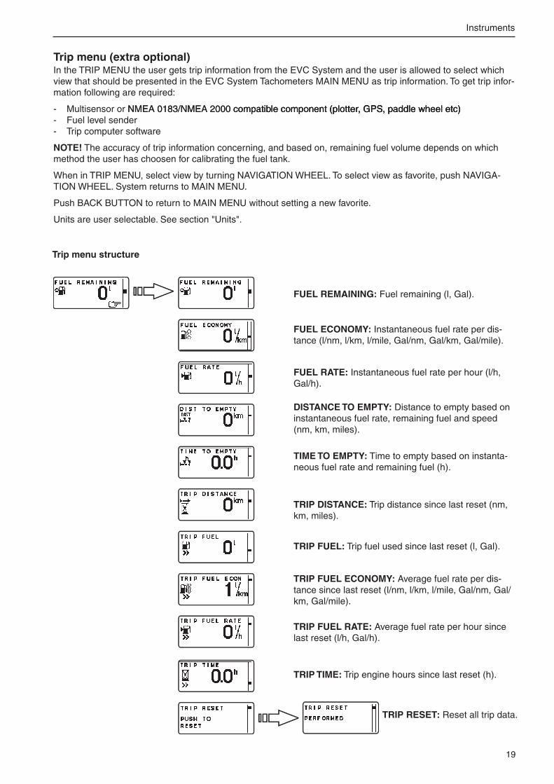
Trip menu (extra optional)In the TRIP MENU the user gets trip information from the EVC System and the user is allowed to select which view that should be presented in the EVC System Tachometers MAIN MENU as trip information. To get trip infor-mation following are required:
- Multisensor or NMEA 0183/NMEA �000 compatible component (plotter, GPS, paddle wheel etc)NMEA 0183/NMEA �000 compatible component (plotter, GPS, paddle wheel etc) compatible component (plotter, GPS, paddle wheel etc) - Fuel level sender - Trip computer software
NOTE! The accuracy of trip information concerning, and based on, remaining fuel volume depends on which method the user has choosen for calibrating the fuel tank.
When in TRIP MENU, select view by turning NAVIGATION WHEEL. To select view as favorite, push NAVIGA-TION WHEEL. System returns to MAIN MENU.
Push BACK BUTTON to return to MAIN MENU without setting a new favorite.
Units are user selectable. See section "Units".
TRIP RESET: Reset all trip data.
FUEL REMAINING: Fuel remaining (l, Gal).
FUEL ECONOMY: Instantaneous fuel rate per dis-tance (l/nm, l/km, l/mile, Gal/nm, Gal/km, Gal/mile).
FUEL RATE: Instantaneous fuel rate per hour (l/h, Gal/h).
DISTANCE TO EMPTY: Distance to empty based on instantaneous fuel rate, remaining fuel and speed (nm, km, miles).
TIME TO EMPTY: Time to empty based on instanta-neous fuel rate and remaining fuel (h).
TRIP DISTANCE: Trip distance since last reset (nm, km, miles).
TRIP FUEL: Trip fuel used since last reset (l, Gal).
TRIP FUEL ECONOMY: Average fuel rate per dis-tance since last reset (l/nm, l/km, l/mile, Gal/nm, Gal/km, Gal/mile).
TRIP FUEL RATE: Average fuel rate per hour since last reset (l/h, Gal/h).
TRIP TIME: Trip engine hours since last reset (h).
Trip menu structure

�0
Instruments
Gauges menuIn GAUGES MENU the user gets information from analogue senders, placed on the engine. If the data is not available the parameter will not be displayed.
When in GAUGES MENU, select view by turning NAVIGATION WHEEL. To select view as favorite, push NAVI-GATION WHEEL. System returns to MAIN MENU.
Push BACK BUTTON to return to MAIN MENU without setting a new favorite.
VOLTAGE: (V)
ENGINE HOURS: (h)
ENGINE RPM: (RPM)
COOLANT TEMP: (°C, °F)
ENGINE OIL PRESSURE: (kPa, PSI)
EXHAUST TEMP: (°C, °F)
TURBO PRESSURE: (kPa, PSI)
TRANSMISSION OIL TEMPERATURE: (°C, °F)
RUDDER ANGLE: (°)
FUEL LEVEL: (%)
FRESH WATER LEVEL: (%)
Gauges menu structure
�1
Instruments
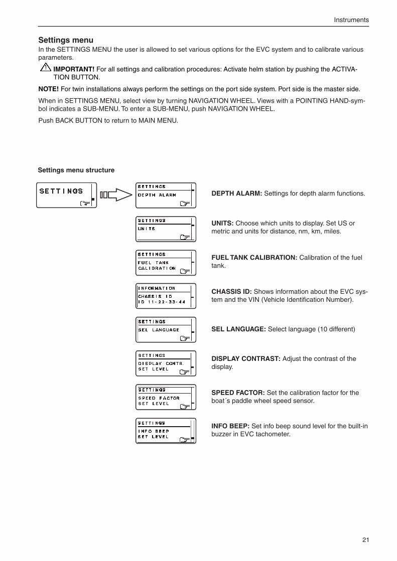
Settings menuIn the SETTINGS MENU the user is allowed to set various options for the EVC system and to calibrate various parameters.
IMPORTANT! For all settings and calibration procedures: Activate helm station by pushing the ACTIVA-TION BUTTON.
NOTE! For twin installations always perform the settings on the port side system. Port side is the master side.
When in SETTINGS MENU, select view by turning NAVIGATION WHEEL. Views with a POINTING HAND-sym-bol indicates a SUB-MENU. To enter a SUB-MENU, push NAVIGATION WHEEL.
Push BACK BUTTON to return to MAIN MENU.
INFO BEEP: Set info beep sound level for the built-in buzzer in EVC tachometer.
DEPTH ALARM: Settings for depth alarm functions.
UNITS: Choose which units to display. Set US or metric and units for distance, nm, km, miles.
FUEL TANK CALIBRATION: Calibration of the fuel tank.
CHASSIS ID: Shows information about the EVC sys-tem and the VIN (Vehicle Identification Number).
SEL LANGUAGE: Select language (10 different)
DISPLAY CONTRAST: Adjust the contrast of the display.
SPEED FACTOR: Set the calibration factor for the boat´s paddle wheel speed sensor.
Settings menu structure

��
Instruments
DEPTH ALARM, ON/OFFDepth alarm can be switched ON/OFF.
SET DEPTHAdjust the depth alarm value by turning the NAVIGA-TION WHEEL. The value can be adjusted at a resolu-tion of 0.1 m or 1 ft.
Once adjustment value is reached, the data is stored by pushing NAVIGATION WHEEL.
DEPTH OFFSETThe depth sounder can be placed somewhere on the hull that gives another depth than the desired depth. You can then add or subtract a distance so that the display shows the depth from, for example, the lowest point on the boat, or from the surface.
Adjust the depth offset value by turning the NAVIGA-TION WHEEL. The value can be adjusted at a resolu-tion of 0.1 m or 1 ft.
Once adjustment value is reached, the data is stored by pushing NAVIGATION WHEEL.
Depth alarm pop-upThe depth alarm pop-up will appear when the depth is less than the depth alarm setpoint. The pop-up shows the actual depth.
Acknowledge depth alarm by pushing NAVIGATION WHEEL.
The depth alarm pop-up will re-appear every 30 sec-onds until the depth increases and exceeds the depth alarm setpoint.
Depth alarm (extra optional)All depth alarm functions are accessed through this menu. A multisensor needs to be installed.
Depth alarm signal lossIf the depth alarm is enabled and the depth signal is lost, for instance in the case of sensor malfunction, the depth alarm signal loss pop-up will appear.
Depth sounder
Waterline
Lowest point

�3
Instruments
Select units and language Choose which units and languages to display.
NOTE! Language and unit settings must be performed in all EVC system tachometers.
US or METRIC1. Activate helm station by pushing the ACTIVATION
BUTTON.
�. Select SETTINGS from MAIN MENU by turn-ing NAVIGATION WHEEL. Push NAVIGATION WHEEL to enter SETTINGS MENU.
3. Select UNITS and push NAVIGATION WHEEL.
4. Select US OR METRIC and push NAVIGATION WHEEL.
5. Set US or METRIC units by turning NAVIGATION WHEEL and confirm by pushing NAVIGATION WHEEL.
DISTANCE1. Activate helm station by pushing the ACTIVATION
BUTTON.
�. Select SETTINGS from MAIN MENU by turn-ing NAVIGATION WHEEL. Push NAVIGATION WHEEL to enter SETTINGS MENU.
3. Select UNITS and push NAVIGATION WHEEL.
4. Select DISTANCE and push NAVIGATION WHEEL.
5. Set distance unit: km, nm or miles and confirm by pushing NAVIGATION WHEEL.
LANGUAGE1. Activate helm station by pushing the ACTIVATION
BUTTON.
�. Select SETTINGS from MAIN MENU by turn-ing NAVIGATION WHEEL. Push NAVIGATION WHEEL to enter SETTINGS MENU.
3. Select SEL LANGUAGE and push NAVIGATION WHEEL.
4. Select language and confirm by pushing NAVIGA-TION WHEEL.

�4
Instruments
Fuel tank calibrationThere are two possible calibration methods for the fuel tank. One approximative, FULL TANK CALIBRATION, and one more precise, FUEL MULTIPOINT CALIBRATION. A fuel level sender need to be installed.
NOTE! If FUEL TANK CALIBRATION is not shown in SETTINGS MENU, please contact your Volvo Penta dealer.
FUEL MULTIPOINT CALIBRATIONWhen FUEL MULTIPOINT CALIBRATION is select-ed, the fuel level sender is calibrated in five equally divided steps; �0% full (pos 1), 40% full (pos �), 60% full (pos 3), 80% full (pos 4) and 100% full (pos 5)
NOTE! To perform multipoint calibration, fuel tankTo perform multipoint calibration, fuel tank must be LESS than �0% full. If calibration skips POS 1 and goes directly to POS �, the fuel tank contains to much fuel and the calibration will not be correct.
1. Activate helm station by pushing the ACTIVA-TION BUTTON.
�. Select SETTINGS from MAIN MENU by turn-ing NAVIGATION WHEEL. Push NAVIGATION WHEEL to enter SETTINGS MENU.
3. Select FUEL TANK CALIBRATION and push NAVIGATION WHEEL.
4. Select FUEL MULTIPOINT CALIBRATION by turning NAVIGATION WHEEL. Push NAVIGA-TION WHEEL to enter FUEL MULTIPOINT CALI-BRATION.
NOTE! The fuel multipoint calibration procedure dif-fers depending on EVC software release.
5A. If the number after “POS” in the display is flashing:
Fill fuel tank with displayed volume (POS 1) and push NAVIGATION WHEEL. Add fuel (do not reset the pump) up to displayed volume for each POS until the tank i filled.
Push BACK BUTTON to return to SETTINGS MENU.
5B. If the number after “POS” is not flashing:
Fill fuel tank with displayed volume (POS 1) and push NAVIGATION WHEEL. Repeat procedure for each POS until the tank is filled.
Push BACK BUTTON to return to SETTINGS MENU.
�5
Instruments
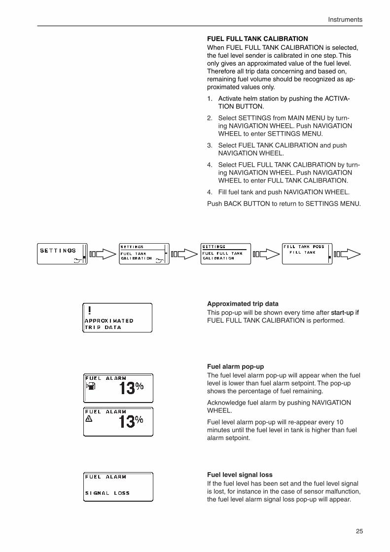
FUEL FULL TANK CALIBRATIONWhen FUEL FULL TANK CALIBRATION is selected, the fuel level sender is calibrated in one step. This only gives an approximated value of the fuel level. Therefore all trip data concerning and based on, remaining fuel volume should be recognized as ap-proximated values only.
1. Activate helm station by pushing the ACTIVA-TION BUTTON.
�. Select SETTINGS from MAIN MENU by turn-ing NAVIGATION WHEEL. Push NAVIGATION WHEEL to enter SETTINGS MENU.
3. Select FUEL TANK CALIBRATION and push NAVIGATION WHEEL.
4. Select FUEL FULL TANK CALIBRATION by turn-ing NAVIGATION WHEEL. Push NAVIGATION WHEEL to enter FULL TANK CALIBRATION.
4. Fill fuel tank and push NAVIGATION WHEEL.
Push BACK BUTTON to return to SETTINGS MENU.
Fuel alarm pop-upThe fuel level alarm pop-up will appear when the fuel level is lower than fuel alarm setpoint. The pop-up shows the percentage of fuel remaining.
Acknowledge fuel alarm by pushing NAVIGATION WHEEL.
Fuel level alarm pop-up will re-appear every 10 minutes until the fuel level in tank is higher than fuel alarm setpoint.
Fuel level signal lossIf the fuel level has been set and the fuel level signal is lost, for instance in the case of sensor malfunction, the fuel level alarm signal loss pop-up will appear.
Approximated trip dataThis pop-up will be shown every time after start-up ifstart-up ifif FUEL FULL TANK CALIBRATION is performed.
�6
Instruments
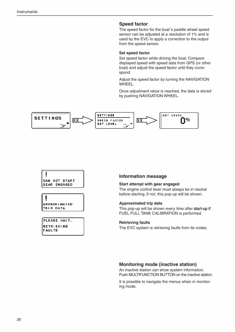
Speed factorThe speed factor for the boat´s paddle wheel speed sensor can be adjusted at a resolution of 1% and is used by the EVC to apply a correction to the output from the speed sensor.
Set speed factorSet speed factor while driving the boat. Compare displayed speed with speed data from GPS (or other boat) and adjust the speed factor until they corre-spond.
Adjust the speed factor by turning the NAVIGATION WHEEL.
Once adjustment value is reached, the data is stored by pushing NAVIGATION WHEEL.
Information message
Start attempt with gear engagedThe engine control lever must always be in neutral before starting. If not, this pop-up will be shown.
Approximated trip dataThis pop-up will be shown every time after start-up ifstart-up ifif FUEL FULL TANK CALIBRATION is performed.
Retrieving faultsThe EVC system is retrieving faults from its nodes.
Monitoring mode (inactive station)An inactive station can show system information. Push MULTIFUNCTION BUTTON on the inactive station.
It is possible to navigate the menus when in monitor-ing mode.

�7
Instruments
EVC System Display (extra optional)IntroductionVolvo Penta EVC system display is an instrument which displays operating information about the engi-ne and allows you to communicate with the engine’s electrical system.
Operation information is shown on an LCD display. The driver can select the display mode operative on the display with the aid of the five buttons on the front of the instrument.
The four buttons at the furthest left are used to dis-play operating information in different ways. The but-ton at the furthest right is used to adjust the display contrast and to access the so-called configuration menu. Various settings etc. can be done in it. You can also use the configuration menu to reach the display mode SYSTEM INFORMATION (which can also be reached via button �, please refer to the schedule below). This display mode functions in the same way as the display in the tachometer (EVC System Tacho-meter).
Before the display is used, it may be necessary to modify the way that the display shows operating in-formation, to comply with user requirements. You can see the settings that can be changed in the section about the configuration menu.
Structure of the display functions
Button 1 Engine(10 different fuel informa-tion)
Button � Multi (display in several win-dows)
Button 3 Trip
Button 4 Graph(display as graphs)
Fuel consumpti-on/time
Fuel consumption
Trip fuel consumption
Numerical display
Instrument display
Zeroing of trip infor-mation
Button 1 de-pressed
Button � depressed
Button 4 de-pressed
Graph display 1
Graph display �
Graph display 3
Button 5
Contrast/Con-figuration
Button 5 depressed for > 3 sec
Button 5depressed
1 � 3 4 5
Contrast
Button 3 de-pressed
Keep button 3 depressed for 3 sec.
Trip info. Configuration menu- System information- Settings- System
System information
More fuel info. available More displays available

�8
Instruments
Display after starting screenDisplay mode ENGINE (button 1) is always shown after the starting screen when the display is first star-ted up (more information about this display mode can be found below in the instructions). Once the display has been used, it will always show the display mode when it starts up, that was selected when the display was last switched off.Figure for single engine
installationFigure for twin engine installation
Connection faultIf the display does not register transfer of operating information from the electrical system, the pop-up window will flash CONNECTION LOST When opera-ting information has been registered/reset, the pop-up window disappears.
Start imageThis is the starting image that is shown on the display for a brief period after starting.
If the unit gives a constant audible warning after star-ting, the self-test has failed. The unit will still work, but may behave in an unexpected manner.
Symbols for operating information
Turbocharge pressure (current)
Induction air temperature
Exhaust temperature
Voltage
Oil pressure, reverse gear
Oil temperature, reverse gear
Fuel level
Differential pressure, oil filter
Engine speed
Coolant temperature
Engine temperature
Fuel pump pressure
Oil pressure
Coolant temperature
Speed
Fuel consumption/time

�9
Instruments
Set display contrastPress button 5 (furthest right) to set display contrast. Then press the appropriate buttons to adapt the le-vels, then save the settings by pressing EXIT. The display unit has 5 contrast settings.
Configuration menu (button 5)(depressed for longer than 3 s)The configuration menu is used to:
- access the display mode SYSTEM INFORMA-TION.
- do various settings for the display.
- reach information and functions for servicing the display.
Please refer to the configuration menu structure be-low and read the following section, which explains each section in the menu.
Note! The port engine or both engines must have the ignition switched on when display settings are chan-ged.
Configuration menu structure
System Information
Language (8 available)Bleep ON, OFF Engine PORT, STARBOARD TWIN, SINGLEEngine series D1/D�, >D�Settings GLOBAL, LOCALDisplay
Units
Settings
System
Engine [�500 rpm: 9000 r/min] in stages of 500 rpmSpeed On, offSpeed [10 KNOT: 100 KNOT] in stages of 10 (in appropriate units)Graph interval �MIN, 10MIN, 30MIN, 60MIN, � H, 4 H, 8 H
Read more about this display mode on the next page
Speed Knots, mph, km/hrDistance NM, Miles, kmOil pressure kPa, psiTurbo pressure kPa, psiFuel consumption Liter/hr, Gal(US)/hr, IGal/hrTemperature degrees C, degrees FVolume Liter, Gal(US), Imperial GallonsDepth (std distance) m, ft
Menu SYSTEMis for ser-vice technicians
The UNITS menu is only available if LOCAL has been selected in the menu SETTINGS
Demo Com Viewer Prog. tx About

30
Instruments
SettingsMenu SETTINGS is used to do various settings for the display.
- Language: This is where you select the language that the display should use (8 different languages are available).
- Bleep: This is where you select whether a beep should be heard when any button is depressed. ON/OFF.
- Engine: This is where you select the engine for which operating data will be displayed. SINGLE, PORT, STARBOARD or TWIN.
- Engine series: This is where you select the engi-ne for which the display has been installed D1/D�, >D�. The display is pre-set for use with engines larger than D�.
Display mode System InformationSYSTEM INFORMATION is a display mode that functions in the same way as the display in the tacho-meter (EVC System Tachometer). You navigate round these functions, using the buttons on the free-stan-ding control panel.
In display mode SYSTEM INFORMATION there are several functions:
- Display of operating information, information mes-sages and alarm (note! The display is adapted to suit the size of the panel in the tachometer).
- Settings for displaying operating information in this display mode.
- All calibrations.
Detailed instructions for the functions in display mode SYSTEM INFORMATION are found in the section about the tachometer in this owner’s manual .
Information message and alarmThe display automatically switches to display mode SYSTEM INFORMATION when the electrical sys-tem needs to show information messages or alarms. Instructions about how information messages and alarms should be handled are found in the section about the tachometer and in the section ”In case of emergency” in this owner’s manual.
SYSTEM INFORMATION display mode for twin engine installations
Control panel
SYSTEM INFORMATION display mode for sin-gle engine installations
Alarm example
31
Instruments
- Display: This is where you set the measurement intervals of the speedometers and tachometers. Rpm engine: [�500 rpm: 9000 r/min] in stages of 500 rpm
- Speed: Change speed display (on/off)
- Speed: [10 KNOT: 100 KNOT] in states of 10 (in the appropriate speed intervals)
- Graph interval: � MIN,10 MIN, 30 MIN, 60 MIN, � H, 4 H, 8 H
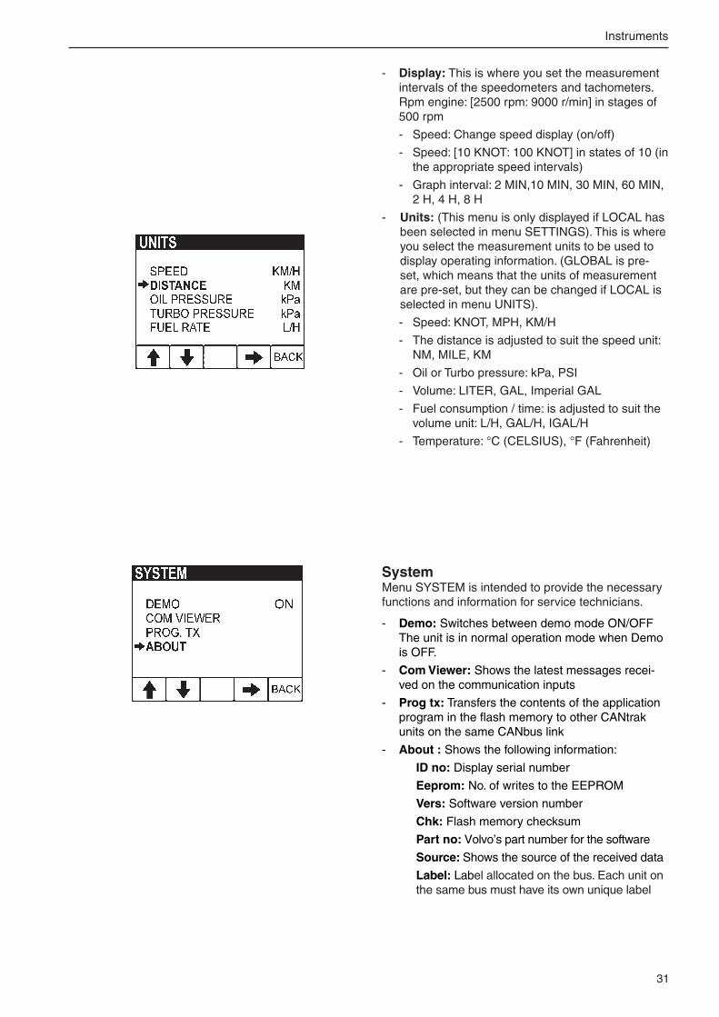
- Units: (This menu is only displayed if LOCAL has been selected in menu SETTINGS). This is where you select the measurement units to be used to display operating information. (GLOBAL is pre-set, which means that the units of measurement are pre-set, but they can be changed if LOCAL is selected in menu UNITS).
- Speed: KNOT, MPH, KM/H
- The distance is adjusted to suit the speed unit: NM, MILE, KM
- Oil or Turbo pressure: kPa, PSI
- Volume: LITER, GAL, Imperial GAL
- Fuel consumption / time: is adjusted to suit the volume unit: L/H, GAL/H, IGAL/H
- Temperature: °C (CELSIUS), °F (Fahrenheit)
SystemMenu SYSTEM is intended to provide the necessary functions and information for service technicians.
- Demo: Switches between demo mode ON/OFF The unit is in normal operation mode when Demo is OFF.
- Com Viewer: Shows the latest messages recei-ved on the communication inputs
- Prog tx: Transfers the contents of the application program in the flash memory to other CANtrak units on the same CANbus link
- About : Shows the following information:
ID no: Display serial number
Eeprom: No. of writes to the EEPROM
Vers: Software version number
Chk: Flash memory checksum
Part no: Volvo’s part number for the software
Source: Shows the source of the received data
Label: Label allocated on the bus. Each unit on the same bus must have its own unique label
3�
Instruments
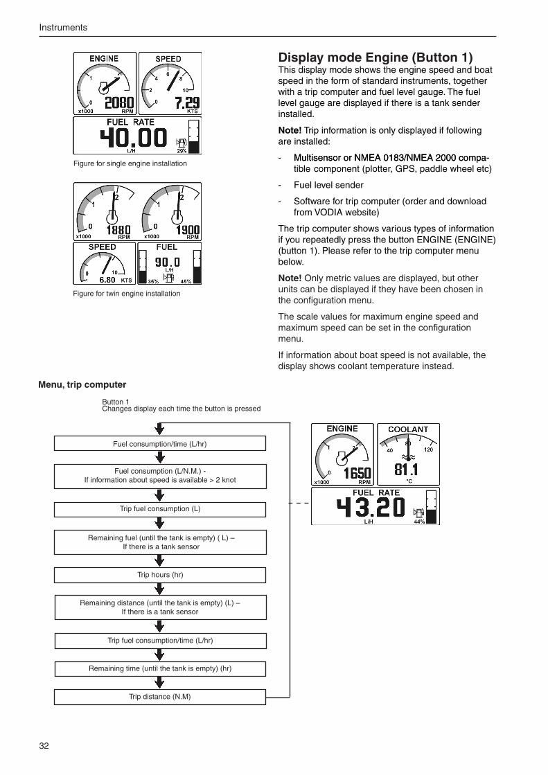
Menu, trip computer
Fuel consumption (L/N.M.) - If information about speed is available > � knot
Trip fuel consumption (L)
Button 1 Changes display each time the button is pressed
Remaining fuel (until the tank is empty) ( L) – If there is a tank sensor
Trip hours (hr)
Remaining distance (until the tank is empty) (L) – If there is a tank sensor
Trip fuel consumption/time (L/hr)
Remaining time (until the tank is empty) (hr)
Fuel consumption/time (L/hr)
Trip distance (N.M)
Figure for twin engine installation
Figure for single engine installation
Display mode Engine (Button 1)This display mode shows the engine speed and boat speed in the form of standard instruments, together with a trip computer and fuel level gauge. The fuel level gauge are displayed if there is a tank sender installed.
Note! Trip information is only displayed if following are installed:
- Multisensor or NMEA 0183/NMEA �000 compa-Multisensor or NMEA 0183/NMEA �000 compa-tible component (plotter, GPS, paddle wheel etc)
- Fuel level sender
- Software for trip computer (order and download from VODIA website)
The trip computer shows various types of information if you repeatedly press the button ENGINE (ENGINE) (button 1). Please refer to the trip computer menu below.
Note! Only metric values are displayed, but other units can be displayed if they have been chosen in the configuration menu.
The scale values for maximum engine speed and maximum speed can be set in the configuration menu.
If information about boat speed is not available, the display shows coolant temperature instead.

33
Instruments
Display mode Multi (button 2) This display mode shows operating information in four different windows (see below). The user can choose the operating information to be displayed in each window.
The information can be displayed as figures or as standard instruments. Display indication shifts bet-ween the two modes when you press button � repea-tedly.
If an item of operating information is not available, the unit displays ”—” and the analogue gauge needle is not shown.
From this display mode MULTI , you can also reach display mode that functions in the same way as the smaller display in the tachometer. Read more about this display mode SYSTEM INFORMATION in the configuration menu section.
Set the appearance of the display mode Multi Display mode MULTI has a mode to set the operating information to be displayed in each window.
The setting mode is reached by pressing button 5 (furthest right), when you are in the display mode MULTI. Please refer to the illustrations below.
Note! The type of operating information available depends on the electrical system in the boat and the sensors that the boat is equipped with. Optional sen-sors include depth gauge, water temperature, speed, trim angle and rudder angle.
Note! This applies to the graphic display: The maximum engine speed range can be set on the configuration menu. The voltage interval can be [8V: 16V] or [16V: 3�V] and is changed automatically, depending on the la-test data value.
Example of display in several windows for twin engine installation
Example of display in several windows for single engine installation
Press button 5 to choose setting mode
Buttons 1 to 4 are used to adjust the corresponding window (please refer to the black markings)
Figure for single engine installation
Figure for twin engine installation
Figure for twin engine installation
Figure for single engine installation

34
Instruments
Window with curve for single engine installation (shows engine speed)
Window with curve for twin engine installation (shows engine speed)
Figure for single engine installation
Figure for twin engine installation
Display mode Graph (button 4)In this display mode, operating information is display-ed in the form of a histograph. Press button 4 repea-tedly to show different operating information.
If an item of operating information is not available, that window can not be chosen.
If contact with the relevant information is lost during display, the curve will no longer be drawn, but the line will continue to scroll across the window.
Data for the port engine or single engine information is drawn with a black line.
Data for the starboard engine information is drawn with a gray line.
The maximum time interval can be set to one of the following values in the configuration menu: � min, 10 min, 30 min, 1 h, � h, 4 h, 8 h. The interval on the Y axis is automatically adjusted for best indication.
Display mode Trip (button 3)This display mode shows:
- Fuel used after last zeroing
- Instantaneous fuel consumption (amount of fuel used per hour) (If speed information is available, instantaneous fuel consumption can also be cal-culated in relation to distance.)
- Operation time after last zeroing
- Total operating time (can not be zeroed)
If you want to zero the trip values (trip fuel consump-tion and trip operating time), keep button 3 depres-sed for 1 second. The unit beeps and the values are zeroed.
Note! When the display is set for a twin engine installation, the information displayed for each engine will be the sum of the values from both engines, apart from operating time. Operation times for twin engines are shown separately.
The size of the operating hours figures shown on the display is reduced if the number does not fit in the window.
35
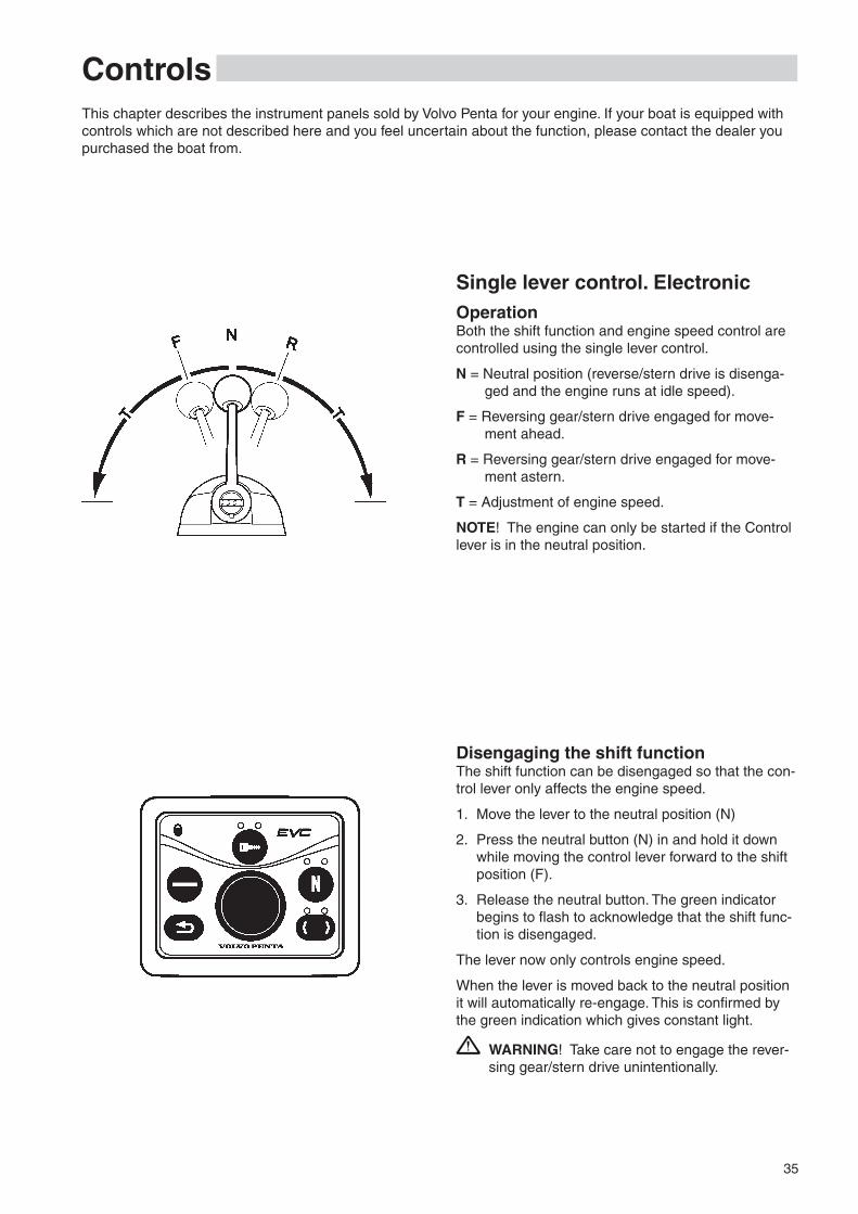
ControlsThis chapter describes the instrument panels sold by Volvo Penta for your engine. If your boat is equipped with controls which are not described here and you feel uncertain about the function, please contact the dealer you purchased the boat from.
Disengaging the shift functionThe shift function can be disengaged so that the con-trol lever only affects the engine speed.
1. Move the lever to the neutral position (N)
�. Press the neutral button (N) in and hold it down while moving the control lever forward to the shift position (F).
3. Release the neutral button. The green indicator begins to flash to acknowledge that the shift func-tion is disengaged.
The lever now only controls engine speed.
When the lever is moved back to the neutral position it will automatically re-engage. This is confirmed by the green indication which gives constant light.
WARNING! Take care not to engage the rever-sing gear/stern drive unintentionally.
Single lever control. ElectronicOperationBoth the shift function and engine speed control are controlled using the single lever control.
N = Neutral position (reverse/stern drive is disenga-ged and the engine runs at idle speed).
F = Reversing gear/stern drive engaged for move-ment ahead.
R = Reversing gear/stern drive engaged for move-ment astern.
T = Adjustment of engine speed.
NOTE! The engine can only be started if the Control lever is in the neutral position.

36
Controls
Friction brakeThe control is also equipped with a friction brake which can be adjusted for easier or stiffer lever movement as necessary.
Friction brake adjustment:
1. Stop the engine.
�. Move the control lever forwards to make the groove in the control lever hub accessible.
3. Put a screwdriver in the groove and disassemble the plug.
4. Adjust the friction brake (spanner size 8 mm):
Clockwise = stiffer lever movement
Anti-clockwise = easier lever movement
5. Install the plug.
37
Controls
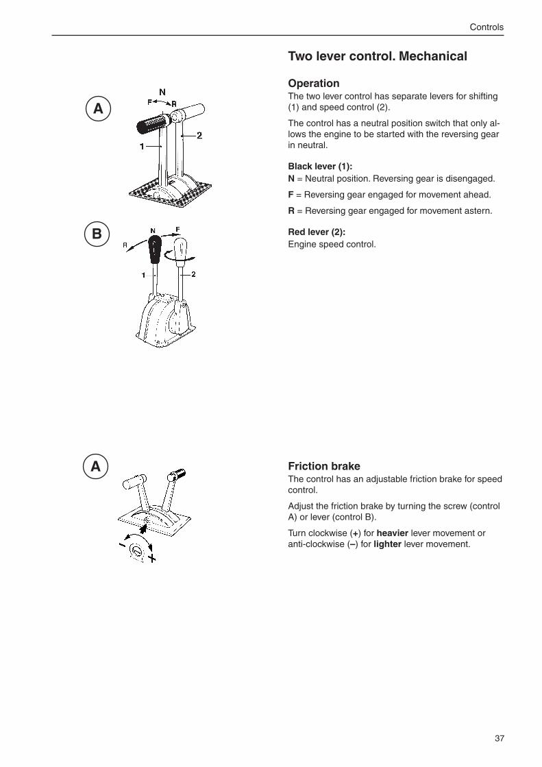
Two lever control. Mechanical
OperationThe two lever control has separate levers for shifting (1) and speed control (�).
The control has a neutral position switch that only al-lows the engine to be started with the reversing gear in neutral.
Black lever (1): N = Neutral position. Reversing gear is disengaged.
F = Reversing gear engaged for movement ahead.
R = Reversing gear engaged for movement astern.
Red lever (2): Engine speed control.
A
B
A
Friction brakeThe control has an adjustable friction brake for speed control.
Adjust the friction brake by turning the screw (control A) or lever (control B).
Turn clockwise (+) for heavier lever movement or anti-clockwise (–) for lighter lever movement.

38
Starting the engineMake it a habit to give the engine and engine bay a visual check before starting. This will help you to discover quickly if anything abnormal has happened, or is about to happen. Also check that instruments and warning dis-plays show normal values after you have started the engine.
To minimize starting smoke in cold starting, we recommend that a heater should be installed to warm the engine bay at temperatures below +5°C.
WARNING! Never use start spray or similar products as a starting aid. Explosion risk!
Before starting● Open the fuel tap
● Open the sea cock (reverse gear)
● Do the tasks under the “Daily before first start” heading in the maintenance schedule.
● Turn the main switches on.
IMPORTANT! Never disconnect the current with the main switches when the engine is running. This can damage the alternator.
● Start the engine bay fan, if one is installed, and let it run for at least four minutes.
● Check that the amount of fuel aboard is enough for your planned voyage.
General information about startingThe engine control lever must always be in neutral before starting. The engine management system en-sures that the engine receives the correct amount of fuel - even when the engine is cold.
The idling speed is also governed by engine tempe-rature, and is somewhat raised after a cold start.

39
Starting the engine
Starting methodPut the reversing gear in neutralPut the reversing gear in neutral by moving the con-trol lever(s) to neutral at all control positions.
Two lever control: Also check that the engine speed lever is in the idling position.
Turn the ignition onTurn the starter key to position I to switch the ignition on.
Check the warning lamps and LEDsEach time the ignition is turned on, all bulbs and LEDs are illuminated on the main control panel. Check that all bulbs and LEDs function.
If the boat has more than one control panel, the lamps on the other panel(s) are not checked until the control panel(s) is(are) activated.
Activate the control position and lock the system.Press the activation button for at least one second. When the button is released, the indication lights up to confirm that the control position is activated.
NOTE! If the indicator flashes, the control position has not been activated because the control lever(s) are not in the neutral position or the system has been locked from another control panel.
If the boat has more than one control panel, the sys-tem can be locked, so that the engine can only be controlled from the activated control board. Press the activation button for a further second to lock the sys-tem. The padlock sign lights up in confirmation.
Unlock the system by pressing the activation button for one second. This can only be done from an activa-ted control panel.

40
Starting the engine
Start the engine
Start using the ignition switchTurn the key to position III. Release the key and let it key spring back to position I as soon as the engine has started.
NOTE! If repeated start attempts are needed, the key must be turned back to position 0 first.
Starting with the starter buttonPress the starter button. Release the button as soon as the engine has started. Please note that if you start from an alternative control station, the starter key at the main control station must be in position I.
Overheating protectionIf the starter motor is engaged for its maximum ac-tivation time (30 seconds), the starter motor circuit is cut automatically to protect the starter motor from overheating. Leave the starter motor to cool for at least five minutes (if possible) before making a new start attempt.
Read the instruments and warm the engine upAllow the engine to idle for the first ten seconds, and check that instruments and warning displays show normal values. Check that no alarms are displayed and that no warning lamps are flashing.
Then warm the engine up at low speed and low load, so that reaches normal operating temperature before full power is used.
IMPORTANT! Never race the engine when it is cold.
Check the oil level in the reverse gear
Check the oil level when the reversing gear has reached operating temperature (please refer to the description in the “Maintenance” chapter under the “Reversing Gear” heading)

41
OperationLearn to handle the engine, controls and other equipment in a safe and correct manner before you cast off on your maiden voyage. Remember to avoid sudden or surprising rudder movements and gear shifting. There is a risk that passengers could fall over, or overboard.
WARNING! A rotating propeller can cause severe injury. Check that there is nobody in the water before you engage forward / aft drive. Never drive close to bathers or in areas where you could reasonably expect that people could be in the water.
Reading the instrumentsRead all instruments and alarm displays directly after starting, and then regularly during your voyage.
Oil pressureThe oil pressure gauge should normally indicate between 4-5.5 bar. It will indicate a somewhat lower value when idling.
If the oil pressure is too low, the audible warning will sound automatically at the same time as the lamp in the warning display will flash.
Coolant temperatureThe temperature gauge should normally indicate bet-ween 75– 95°C (167-�03°F) in normal operation.
If the coolant temperature is too low, the audible war-ning will sound automatically at the same time as the lamp in the warning display will flash.
ChargingDuring operation, system voltage should be about �8 V for �4 Volt system voltage.
If there is a charge failure, the audible warning will sound automatically at the same time as the lamp in the warning display will flash.

4�
Operation
AlarmIf a fault occurs, the audible warning will sound and the relevant warning lamp on the alarm panel will start to flash and the display will show a alarm pop-up.
1. Reduce engine speed to idling.
�. Acknowledged the larm by pressing the naviga-ton wheel on the control panel once.
When the fault has been acknowledged, the lamp concerned gives constant light and the audible war-ning will become silent.
Please refer to the “In case of emergency” chapter, and you will find detailed information about recom-mended action in the “Diagnostic function” section.
The fault will also be stored in the form of a fault code for as long as the malfunction remains. It is possible to read the fault code during a subsequent service.
Cruising speedAvoid operation at full throttle, for best fuel economy. We recommend a cruising speed which is at least 10% below the maximum engine speed at full speed (full throttle). The maximum engine speed will vary due to propeller choice, load and sea conditions, but it should be in the full throttle range.
Full throttle range: D1�D-C MH rating 1 .......... 1800–1850 rpm. rating � .......... 1900–1950 rpm.
If the engine does not reach the full throttle range, this could be caused by a number of factors which are noted in the “Fault tracing” chapter. If the engine speed exceeds the full throttle range, select a coar-ser pitch propeller. Ask your Volvo Penta dealer for advice.

43
Operation
Synchronizing engine speedWhen driving with twin engines, both the operating economy and comfort will be increased when the engines are operating at the same engine speed (rpm).
When the synchronization function is activated, the engine speed (rpm) of the starboard engine is au-tomatically adjusted to that of the port engine. The synchronization function is activated automatically if the following conditions are met.
1. The engine speed levers for both engines are in (approximately) the same position.
�. The engine speed on both engines must exceed 800 rpm.
NOTE! The synchronizer is disengaged as soon as the conditions are no longer met.
1
Changing the helm station The first time you change control panel after starting the EVC system, a bulb check is done automatically. All LEDs and bulbs light up for � seconds.
1. Check that the control lever(s) is (are) in neutral on both the control panel you leave and on the new control panel.
�. Check that the EVC system is not locked.
3. Press the activation button (1) for at least one se-cond. When the button is released, the indication lights up to confirm that the control position is ac-tivated.
4. Press the activation button (1) for a further second to lock the EVC system. The padlock sign lights up in confirmation. Unlock the system by pressing the activation button for one second. This can only be done from an activated control panel.

44
Operation
Changing helm station while cruising (optional)
This function must be enabled to permit the control panel to be changed during operation. The function can only be enabled by authorized Volvo Penta per-sonnel. Please contact your Volvo Penta dealer.
1. Press the activation button (1) to unlock the sys-tem. The padlock sign goes out on all control pa-nels to indicate that it is possible to change control panel.
�. The control lever on the alternative control panel must be in neutral before it is possible to change control panel.
3. Press the activation button (1) on the alternative control panel. The activation button indication flas-hes on the alternative control panel, and on the main control panel it gives constant light.
4. The alternative control panel becomes active when the correct gear and approved engine speed is demanded. The activation button (1) gi-ves constant light to confirm that the control panel is activated. The system is now locked, which is indicated by the padlock sign, which lights up.
NOTE! If the correct gear or engine speed is not demanded within 15 sec, the system ramps engine speed down to neutral and the gearbox engages neutral.

45
Operation
OperationShifting between forward and reverse should be done at idling. Shifting at higher engine speeds can be un-comfortable for passengers and cause unnecessary stress on the stern drive/reversing gear, or cause the engine to stop.
If you attempt to shift gear at an excessive engine speed, a safety function cuts in automatically, and delays shifting until engine speed has fallen to 1000 rpm.
Always do a forwards/reverse operation as fol-lows:
1. Reduce engine speed to idle and let the boat more or less lose way.
WARNING! Never shift to reverse when the boat is planing.
�. Move the control lever to neutral with a rapid, dis-tinct movement. Make a brief pause.
NOTE! A beep will sound to indicate that the con-trol lever is in neutral.
3. Then move the control lever to reverse with a rapid, distinct movement and increase engine speed.
IMPORTANT! If the boat has twin engines, it is important that both should be running during reversing maneuvers, to avoid the risk of water entry (via the exhaust pipe) into the stationary engine.
1
�
3

46
Operation
Lowspeed (option)The Lowspeed function is only available for engines with hydralic reverse gear.
For boats with powerful engines, where the boat speed at idle is too high, Lowspeed is used to reduce boat speed by reducing propeller rpm - compared to normal at engine idle speed.
N = Neutral idling (reverse gear disengaged, engine runs at idle speed)
F = Forward idling (reverse gear engaged for move-ment ahead, engine runs at idle speed), maxi-mum slip in reverse gear.
R = Reverse idling (reverse gear engaged for move-ment astern, engine runs at idle speed), maxi-mum slip in reverse gear.
A = Lowspeed active. Propeller rpm is increased with increase of throttle, engine rpm is not affected.
B = Lowspeed deactivated. Propeller rpm is in-creased with engine rpm, engine rpm will in-crease with throttle.
Engaging Lowspeed1. Move the lever to neutral position.
�. Press the neutral button (N) to activate Lowspeed. When Lowspeed is engaged a pop-up (A) is shown on the tachometer display. It is pos-sible to acknowledge pop-up by pushing NAVIGA-TION WHEEL.
3. Active Lowspeed is indicated by an icon, , on the tachometer display (D).
IMPORTANT! If Lowspeed initializing pop-up (B) and then icon, , are shown on the tachome-ter display (C), Lowspeed is not ready to use. Normal gear shifting until Lowspeed is activated (D).
IMPORTANT! Delay in gear shifting may occur when Lowspeed is active.
Disengaging Lowspeed1. Move the lever to neutral position.
�. Press the neutral button (N) to deactivate Lowspeed. A pop-up (E) is shown on the tacho-meter display. It is possible to acknowledge pop-up by pushing NAVIGATION WHEEL.
3. The indication in tachometer display goes out.
Lowspeed activated - Function active.
Lowspeed initializing - Low-speed is not ready to use. (Twin disc)
Pop-up when initializing Low-speed - Lowspeed is not ready to use.(Twin disc)
Pop-up when Lowspeed is engaged. It is possible to ac-knowledge pop-up by pushing NAVIGATION WHEEL.
Pop-up when Lowspeed is dis-engaged. It is possible to ac-knowledge pop-up by pushing NAVIGATION WHEEL.
(A)
(B)
(C)
(D)
(E)

47
Operation
Trolling (option)The Trolling function is only available for engines with hydralic reverse gear.
Trolling requires two control levers, one for throttle/gear, and the other to control the slip function. Trolling makes it possible to use higher engine power without increasing boat speed.
WARNING! If engine speed exceeds the maxi-mum permissible engine speed for trolling (ap-prox. 1000 rpm, depending on reverse gear), the EVC system automatically disengages trolling and full propeller effect returns. Depending on the position that the control lever is in when au-tomatic disengagement occurs, the boat speed can increase rapidly.
OperationMove the throttle/gear lever to a position where the engine speed is within the permissible engine speed range and move the slip control lever to a slip posi-tion. Active Trolling is indicated by an icon, on the tachometer display (B).
IMPORTANT! If Trolling initializing icon, , is shown on the tachometer display (A), Trolling is not ready to use. Normal gear shifting until Trol-ling is activated.
NOTE! At maximum slip there is no propeller effect.
Move the slip control lever to minimum slip position to deactivate Trolling. The indication in the tachometer display goes out.
IMPORTANT! Delay in gear shifting may occur when Trolling is active.
Trolling initializing - Trolling is not ready to use. (Twin disc)
Trolling activated - Function active. Slip control lever in slip position.
(B)
(A)

48
Operation
Propeller shaft brakeIn certain conditions, the propeller can make the pro-peller shaft rotate when the engine is stopped. This parasitic rotation is uncomfortable, and can damage the reversing gear since its oil pump, which is driven by the input shaft, is stationary together with the engine.
The propeller shaft can be permitted to rotate with a stationary engine for up to 6-8 h. After this, the engine must be started and run for at least 5 min to lubricate and cool the reversing gear.
If the shaft is likely to rotate faster than in normal operation, such as when sailing, a temperature gau-ge should be installed to monitor the oil temperature.
Maximum permissible temperature is 95°C for the ZF reversing gear.
When the above-mentioned rules can not be met, or if you want to stop the shaft for comfort reasons, a shaft brake has to be installed. On isolated occa-sions, the propeller shaft flange can be locked me-chanically by some suitable means.
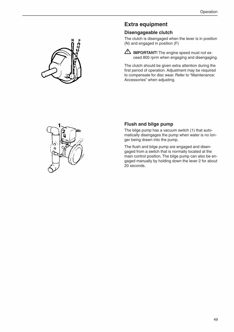
49
Operation
Extra equipmentDisengageable clutchThe clutch is disengaged when the lever is in position (N) and engaged in position (F)
IMPORTANT! The engine speed must not ex-ceed 800 rprm when engaging and disengaging.
The clutch should be given extra attention during the first period of operation. Adjustment may be required to compensate for disc wear. Refer to “Maintenance: Accessories” when adjusting.
Flush and bilge pumpThe bilge pump has a vacuum switch (1) that auto-matically disengages the pump when water is no lon-ger being drawn into the pump.
The flush and bilge pump are engaged and disen-gaged from a switch that is normally located at the main control position. The bilge pump can also be en-gaged manually by holding down the lever � for about �0 seconds.

50
Stopping the engine
Stop1. Disengage the reversing gear by putting the con-
trol lever in neutral.
�. Turn the key to stop position “S”. Keep the key turned until the engine stops. The key will auto-matically return to the “0” position when it is re-leased and can then be removed.
IMPORTANT! Never switch off the main swit-ches while the engine is running. This could da-mage the alternator.
IMPORTANT! Never switch off the main swit-ches before the starter key is turned off (is in “0” position or removed). This could damage the electrical system.
After stopping● Check the engine and engine bay for leakage.
● Shut off the fuel taps and sea cocks.
IMPORTANT! Do not forget to open the taps next time the engine is started.
● Read off the hours counter and do preventive maintenance as in the maintenance schedule.
● Turn off the main switches before any long stopp-age.
IMPORTANT! Never switch off the main swit-ches before the starter key is turned off (is in “0” position or removed). This could damage the electrical system.
Allow the engine to idle (in neutral) for at least three minutes after the end of your journey. This evens out the temperatures inside the engine, and stops after-boiling.
IMPORTANT! The above is particularly important if the engine has been driven at high speed and/or hea-vily loaded.
Auxiliary stopIf a fault occurs that prevents you stopping the engine in the normal way, you can stop it by pressing the emer-gency button.
If the engine has been stopped using the emergency stop button, the button locks in the down position. In order to be able to restart the engine, the button must be reset to its original position. To do this, pull the button upwards until you hear a click.
WARNING! Working with, or going close to a running engine is a safety risk. Watch out for ro-tating components and hot surfaces.

51
Stopping the engie
Cold weather precautionsIf the engine bay can not be kept frost-free, the sea-water system must be drained and the freshwater system coolant must have enough anti-freeze to pre-vent frost damage. Please refer to the “Seawater sys-tem” and “Freshwater system” maintenance chapters.
WARNING! If the engine bay can not be kept frost-free, the seawater system must be drained. Frost damage in the seawater system can make the boat sink.
IMPORTANT! If the coolant does not have suf-ficient frost protection, this can cause expensive engine damage. Check the battery charge. A poorly charged battery can freeze and burst.
Laying upIf the boat is not used, but left in the water, the engi-ne must be warmed up at least once every fortnight. This prevents corrosion damage in the engine.
IMPORTANT! If you expect the boat to be unu-sed for two months or more, it must be laid up: Please refer to the Laying up chapter.

5�
MAINTENANCE SCHEDULE WARNING! Before you start to do any maintenance work, read the “Maintenance”
chapter carefully. This contains instructions for doing work in a safe and correct man-ner.
IMPORTANT! When both operation and calendar time are specified, do the mainte-nance job at the interval which is reached first. Maintenance points marked must be done by an authorised Volvo Penta workshop.
Daily, before first start● Engine and engine bay. General inspection .................................................. page 54
● Air filter indicator. Inspection 1) ...................................................................... page 55
● Engine oil. Check level ................................................................................... page 58
● Coolant. Check level ...................................................................................... page 63
● Fuel filter. Drain water/contamination ........................................................... page 71
● Reverse gear. Check oil level (after starting) ................................................. page 811) Change the air filter every 1� months.
After the first 50 hours● Reverse gear. Oil strainer. Cleaning ............................................................. page 81
● Reverse gear. Oil. Change ............................................................................ page 8�
Every 50 hours / at least every 12 months● Reverse gear. Seal. Lubrication.................................................................... page 8�
● Disengageable clutch. Lubrication 1) ............................................................ page 83
Every 50-500 hours / at least every 12 months● Engine oil Change �) ..................................................................................... page 58
● Oil filter / Bypass filter. Change 3) .................................................................. page 60
1) Applies to release bearing when operated more than 15 times a day. Otherwise, every 500 operating hours.�) Oil change intervals vary, depending on oil grade and sulphur content of the fuel. Please refer to page 57.3) Change the filters during each oil change.
Maintenance scheduleGeneral informationYour Volvo Penta engine and its equipment are designed for high reliability and long life. They are built to withstand a marine environment, but also to have the smallest possible environmental impact. If given preventive maintenance, according to the maintenance schedule, and if Volvo Penta original spares are used, these quali-ties are retained and unnecessary malfunctions can be avoided.
Warranty inspectionDuring the first period of operation, the specified warranty inspection “First service inspection” must be done by an authorised Volvo Penta workshop. Instructions about when and where this should be done are found in the Warranty and service book.

53
Maintenance schedule
Every 250 hours / at least every 12 months● Fuel pre-filter (twin filter). Inspection 1) ............................................................... page 741) Only applies to the double filter: Check the pressure gauge and change the filter as
necessary every 1000 hours of operation, or at least once every 1� months.
Every 500 hours / at least every 12 months● Crankcase ventilation. Change filter ................................................................... page 55
● Drive belts. Inspection/adjustment ...................................................................... page 56
● Coolant (corrosion protection mixture). Topping up 1) ........................................ page 63
● Zinc anodes. Change ......................................................................................... . page 67
● Seawater pump. Check/change the impeller ...................................................... page 68
● Batteries. Checking the electrolyte ..................................................................... page 771) Top up with ½ litre corrosion protection fluid. IMPORTANT! This only applies if the
cooling system is filled with a corrosion protection mixture (not a glycol mixture).
Every 1000 hours / at least every 12 months Valve clearance. Inspection/adjustment...........................................................not shown
● Coolant filter. Change 1) ..................................................................................... page 65
Clean the insert in the heat exchanger and in the reverse gear oil cooler ......not shown
● Seawater filter. Checking/cleaning �) .................................................................. page 68
● Fuel pre-filter. Change filter insert ..................................................................... page 74
● Fuel fine filter. Changing. Venting the fuel system .............................................. page 70
● Reverse gear. Oil strainer. Cleaning ................................................................... page 81
● Reverse gear. Oil. Change .................................................................................. page 8�1) Not at same time as coolant change.�) Adjust the time by experience, after a period of operation.
Every 2000 hours Turbocharger. Inspection .................................................................................not shown
Every 12 months EVC system. Inspection with diagnosis tool ....................................................not shown
Engine and reverse gear. General inspection ..................................................not shown
● Air filter insert. Change ..................................................................................... page 55
● Flushing/Bilge pump. Check the impeller ........................................................not shown
● Engine and reverse gear. Cleaning/painting ....................................................not shown
Every 24 months Cooling system Inspection/cleaning ................................................................not shown
Coolant. Change ................................................................................................. page 6�

54
Maintenance
Engine, general
General inspectionMake it a habit to give the engine and engine bay a “visual” check before driving before starting the engine and after operation when you have stopped the engine. This will help you to discover if anything abnormal has happened, or is about to happen.
Look especially carefully at oil, fuel and coolant lea-kage, loose screws, worn or poorly tensioned drive belts, loose connections, damaged hoses and elec-trical cables. This inspection only takes a few minutes and can prevent serious malfunctions and expensive repairs.
WARNING! Deposits of fuel, oils and grease on the engine or in the engine bay are a fire hazard and must be removed as soon as they are dis-covered.
IMPORTANT! If you discover a leakage of oil, fuel or coolant, investigate the cause and fix the fault before you start the engine.
IMPORTANT! Observe the following when cleaning with a high pressure washer: Never aim the water jet at seals, rubber hoses or elec-trical components. Never use a high pressure washer for engine cleaning.
This chapter contains general technical information and instructions for carrying out the specified maintenance points. Read them carefully before starting work. The times when maintenance points need to be attended to are given in the previous chapter: Maintenance schedule
WARNING! Read through the safety advice for care and maintenance work in the Safety information chapter before you start work.
WARNING! Care and maintenance work should be done with the engine stopped unless otherwise spe-cified. Stop the engine before opening or removing the engine hatch/hood. Make it impossible to start the engine by removing the start key and cutting the system voltage with the main switches.
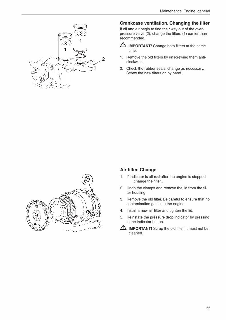
55
Maintenance. Engine, general
Crankcase ventilation. Changing the filterIf oil and air begin to find their way out of the over-pressure valve (�), change the filters (1) earlier than recommended.
IMPORTANT! Change both filters at the same time.
1. Remove the old filters by unscrewing them anti-clockwise.
�. Check the rubber seals, change as necessary. Screw the new filters on by hand.
Air filter. Change 1. If indicator is all red after the engine is stopped,
change the filter..
�. Undo the clamps and remove the lid from the fil-ter housing.
3. Remove the old filter. Be careful to ensure that no contamination gets into the engine.
4. Install a new air filter and tighten the lid.
5. Reinstate the pressure drop indicator by pressing in the indicator button.
IMPORTANT! Scrap the old filter. It must not be cleaned.

56
Maintenance. Engine, general
Drive belts. Inspection/adjustment WARNING! Stop the engine before doing any
maintenance work.
General informationCheck belt tension and condition regularly. A belt which is to tense can damage the bearings and a belt which is too loose can slip.
IMPORTANT! Always change a belt which looks worn or cracked (belts which operate in pairs must be changed together).
Alternator belt(s)The standard alternator, plus the extra alternator if installed, are driven by a Poly-Vee belt each, for best function and service life. The belts are tensioned in the same way.
1. Remove the protective cover over the alternator drive belt.
�. Undo the inner fixing screw (1) and the lock screws (�) a couple of turns.
3. Tension the belts with tensioner screw (3). It should be possible to press the belts down about 5 mm (0.�”) between the pulleys when the ten-sion is correct.
4. Tighten lock screw (�) and the inner fixing screw (1).
5. Install the protective cover over the alternator drive belt.
Other beltsThe flushing and bilge pump etc. are driven by tra-ditional drive belts. In general, it should be possible to press these belts down 10 mm (0.4”) between the pulleys when the tension is correct.
When you change a drive belt: Clean the belt grooves before installing the new drive belt.

57
Maintenance. Lubrication system
Lubrication system
Oil change intervals can vary from 50 to 500 hours, depending on oil grade and sulphur content of the fuel. Note that oil change intervals must never exceed a period of 12 months.
If you want longer oil change intervals than given in the table below, the condition of the oil must be checked by the oil manufacturers through regular oil testing.
SAE5W/30
−−−−−30 −−−−−20 −−−−−10 ±0 +10 20 30 40
−−−−−22 −−−−− 4 +++++14 32 50 68 86 104
−−−−−15oC SAE15W/40
−−−−−25oC SAE10W/30
−−−−−10oC SAE20W/30
±0oC SAE30
SAE40+10oC
oC
oF
✱✱✱✱✱
ViscositySelect the viscosity from the table below.Note. The temperature values refer to stable ambient temperatures.
* Refers to synthetic or semi-synthetic oils.
Oil change volumePlease refer to the “Technical Data” chapter.
Oil grade 1) Sulphur content in fuel, by weight
up to 0.5% 0.5 –1.0% more than 1.0% 2)
Oil change interval: Reached first in operation: VDS-3 500 hr. or 1� months. 250 hr. or 1� months. 125 hr. or 1� months.
VDS-2 and ACEA E7 4) or VDS-� and Global DHD-1 500 hr. or 1� months. 200 hr. or 1� months. 100 hr. or 1� months. or VDS-� and API CH-4 or VDS-� and API CI-4
VDS and ACEA E3 �) 300 hr. or 1� months. 150 hr. or 1� months. 75 hr. or 1� months. or VDS-� and API CG-4 3)
NOTE! Mineral based oil, either fully or semi-synthetic, can be used on condition that it complies with the quality requirements above.1) When oil quality specifications are joined by ”and” the engine oil must fulfill both requirements. �) If sulphur content is > 1.0% by weight, use oil with TBN > 15.3) ACEA E7 has replaced ACEA E5, but if available ACEA E5 can be used.4) ACEA E3 can be replaced by ACEA E4, E5 or E7.
VDS = Volvo Drain SpecificationACEA = Association des Constructeurs Européenne d’AutomobilesAPI = American Petroleum InstituteTBN = Total Base NumberGlobal DHD = Global Diesel Heavy Duty

58
Maintenance. Lubrication system
Oil level. Checking and fillingThe oil level must be inside the marked area on the dipstick (1) and should be checked daily before the first start.Top up the oil through the filling hole on the side of the engine (�) . Check that the correct level has been achieved. But wait a few minutes to allow the oil to run down into the sump.
IMPORTANT! Do not fill up above the maximum oil level. Only use a recommended grade of oil (please refer to previous page).
Engine oil. ChangeAlways observe the recommended oil change interval.
1. Warm the engine up (this makes it easier to suck the oil up from the sump). Then stop the engine.
WARNING! Hot oil and hot surfaces can cause burns.
�. Connect the suction pipe of the oil drain pipe to the drain pipe. Pump up the oil.
3. Change the oil filter and bypass filter at each oil change (please refer to the instructions on the next page).
4. Fill up with oil to the correct level through the fill-ing hole on the side of the engine (please refer to the “Technical Data” chapter for oil volume).
IMPORTANT! Only use a recommended grade of oil (please refer to previous page).
5. Start the engine and let it idle. Check that the low oil pressure warning lamp goes out and that no leakage occurs by the filters.
WARNING! Working with, or going close to a running engine is a safety risk.Watch out for rotating components and hot surfaces.
6. Stop the engine. Wait a few minutes before checking the oil level. Top up as necessary.
NOTE! Hand the old oil in to a re-cycling station.

59
Maintenance. Lubrication system
Switchable oil filters IMPORTANT! Though possible, the switchable
filters should not be replaced during engine ope-ration other than in case of an emergency
1. Clean the filter bracket.
�. Disconnect the left filter by turning the lever to the right-hand end position. To unlock the lever, pull the knob beneath the lever downwards.
3. Unscrew the left-hand oil filter and discard it. Use a filter wrench if necessary.
4. Check that the mating surfaces on the filter bracket are clean, and that no traces of the seal from the old filter remain.
5. Oil the rubber seal for the new filter.
6. Screw the filter on by hand until the rubber seal just touches the mating surface of the filter brack-et. Then tighten the filter a further 3/4 of a turn.
7. Turn the lever to the left-hand end position and change the right-hand oil filter in the same way.
8. Put the lever in operating position (straight up).
9. If necessary, top up the system with lubrication oil at first stop. Refer to section “Lubrication oil change”.

60
Maintenance. Lubrication system
Oil filter and bypass filter. Change Change the oil filter and bypass filter during each oil change.
Remember to hand the old filters in to a re-cycling sta-tion.
WARNING! Hot oil and hot surfaces can cause burns.
1. Put a suitable vessel underneath the filters to avoid oil spillage.
�. Clean the filter bracket.
3. Unscrew the bypass filter (1) and the oil filters (�) with a suitable extractor.
4. Check that the mating surfaces on the filter brack-ets are clean, and that no residue from the old seals remains.
5. Moisten the seals on the new filters with engine oil.
6. Screw the filters on by hand until the rubber seals just touch the mating surface on the filter brack-ets. Then tighten a further 1/� to 3/4 turn.
7. Start the engine (low idle) and check that no leak-

61
Maintenance. Freshwater system
Fresh water system
The fresh water system is the engines’ internal cooling system, which ensures that the engine operates at the correct temperature. It is a closed circuit system and must always be filled with a mixture of at least 40 % con-centrated coolant and 60 % water to protect against internal corrosion, cavitation and damage caused by freez-ing.
We recommend that you use “Volvo Penta Coolant, Ready Mixed”, alternatively “Volvo Penta Coolant” (con-centrated) mixed with pure water according to spec, see “Coolant. Mixture”. Only coolant of this quality is suited too and approved by Volvo Penta.
The coolant should contain ethylene glycol of a good quality with a suitable chemical consistency for an ade-quate protection of the engine. Using anti-corrosion aditive exclusively is not permitted in Volvo Penta’s engines. Never use water by itself as coolant.
IMPORTANT! Coolant must be used all year round. This applies even if there is never any risk for frost , to ensure that the engine has an adequate protection against corrosion. Future warranty claims on the engine and additional equipment may be rejected if an unsuitable coolant has been used or if the instructions concerning coolant mixing have not been followed.
NOTE: The anti-corrosive agents become less effective after a time, which means that the coolant must be re-placed, see “Service schematic”. The cooling system should be flushed out at the same time as the coolant is replaced, see “Cooling system. Flushing”.
“Volvo Penta Coolant” is a concentrated coolant that is to be mixed with water. It has been developed to function optimally with Volvo Penta’s engines and provides excellent protection against corrosion, cavi-tation and frost damage.
“Volvo Penta Coolant, Ready Mixed” is a ready-mixed coolant, 40% “Volvo Penta Coolant” and 60% water. This concentration protects the engine against corrosion, cavitation damage and freezing conditions down to -�8 °C (-18°F).

6�
Maintenance. Freshwater system
Coolant. Mixture WARNING! All glycol is hazardous and harmful
to the environment. Do not consume! Glycol is flammable.
IMPORTANT! Ethylene glycol must not be mixed with other types of glycol.
Mix: 40 % “Volvo Penta Coolant” (conc. coolant) 60 % water
This mixture protects the engine against internal cor-rosion, cavitation and frost damage down to -�8 °C (18°F). (Using 60 % glycol lowers the freezing point to -54 °C (-65°F)). Never mix more than 60 % con-centrate (Volvo Penta Coolant) in the cooling liquid, this will give reduced cooling effect and increase the risk of overheating, and will give reduced freezing protection.
IMPORTANT! Coolant must be mixed with pure water, use distilled - de-ionized water. The water must fulfill the requirements specified by Volvo Penta, see “Water quality”.
IMPORTANT! It is extremely important that the correct concentration of coolant is added to the system. Mix in a separate, clean vessel before adding into the cooling system. Ensure that the liquids mix properly.
Water quality
ASTM D4985:
Total solid particles ........................................ < 340 ppm
Total hardness:............................................... < 9.5° dH
Chloride ......................................................... < 40 ppm
Sulfate ............................................................ < 100 ppm
pH value ......................................................... 5,5–9
Silica (acc. ASTM D859) ................................ < �0 mg SiO�/l
Iron (acc. ASTM D1068) ................................ < 0.10 ppm
Manganese (acc. ASTM D858) ...................... < 0.05 ppm
Conductivity (acc. ASTM D11�5) ................... < 500 µS/cm
Organic content, CODMn (acc. ISO8467) ....... < 15 mg KMnO4/l

63
Maintenance. Freshwater system
Coolant level. InspectionNote. Coolant level can be checked through a level glass on top of the expansion tank.
The green float must be visible in the level glass.
WARNING! Never open the pressure cap when the engine is hot. Steam or hot coolant can spray out at the same time as the pressure which has built up is lost.
The coolant level should be about five centimetres (�”) below the pressure cap sealing plane in the expansion tank.
If a separate expansion tank is installed, the coolant level must be between the MAX and MIN markings. Top up the coolant as necessary, following the de-scription below.
Coolant. Filling WARNING! Stop the engine and let it cool be-
fore filling. Hot fluids and hot surfaces can cause burns.
IMPORTANT! Top up with the same type of coolant as already used in the system.
Topping upFill up with coolant to the correct level via the filling hole on the expansion tank. Fill slowly, to allow the air which is forced out a chance to flow out of the filling hole.
When you fill up an empty system, or if the coolant has fallen so low for any reason that it is no longer visible through the filling hole, fill up as in the de-scription for “Filling a completely empty system”.
Filling a completely empty system1. Mix a sufficient quantity of coolant in a vessel be-
fore filling. Please note that a heating system, tap water heater etc. if connected to the engine cool-ing system, mean that a correspondingly greater amount of coolant will be needed.
�. Open the vent tap by the turbocharger.
3. Also ensure that the heating system, tap water heater etc. if connected to the engine cooling system, are also vented (open the heater control valve).

64
Maintenance. Freshwater system
F F
F F
1V
4. Fill up with coolant via the filling hole on the ex-pansion tank.
Fill slowly, to allow the air which is forced out a chance to flow out of the vent tap(s) and filling hole.
5. Close the vent tap(s) as and when air-free coo-lant flows out.
6. Fill up with coolant to about 5 cm (�”) below the filling cap seal plane.
7. Start the engine and let it idle for about 1 hour.
IMPORTANT! Do not start the engine until the system is vented and completely filled.
8. Stop the engine and let it cool. Check the coolant level. Top up as necessary.
Coolant. Draining. WARNING! Stop the engine and let it cool be-
fore draining. Hot fluids and hot surfaces can cause burns.
WARNING! Glycol is poisonous (dangerous to drink). Collect the old coolant and hand it to a re-cycling station for destruction. Drain the cool-ant via taps (F).
1. Remove the filling cap (1) from the expansion tank.
�. Open the vent tap (V) by the turbocharger.
3. Connect a suitable hose to each drain tap. Open the tap and allow the coolant to drain off into a suitable vessel.
IMPORTANT! Check that all coolant really does drain out. Deposits may need to be cleared away, inside the drain plug(s)/tap(s).
4. Continue with all the drain points until all five have been opened and all coolant has been drained off.
5. Also drain the heating system, tap water heater etc., if connected to the engine’s freshwater system.
6. Close all drain taps.

65
Maintenance. Freshwater system
1
Freshwater system. FlushingThe cooling system should be flushed when the cool-ant is changed, to avoid loss of cooling performance due to deposits in the cooling system.
1. Drain the coolant, as in the description on the previous page.
�. Put a hose into the filling hole in the heat ex-changer and flush with fresh water.
3. Flush until the water which runs out of the drain points is clean.
4. Close all drain points when all coolant has run out.
5. Fill up with coolant, as in the description on the previous page.
Coolant filter. Change IMPORTANT! Do not change the filter when the
coolant is changed. The concentration of rust-preventer in the coolant can become too high, which would cause foaming and impaired cool-ing.
WARNING! Hot coolant and hot surfaces can cause burns.
1. Clean the filter bracket.
�. Close the filter tap (1), (position A).
3. Unscrew the filter with a suitable extractor.
4. Clean the filter mating surface on the filter bracket.
5. Moisten the seals on the new filter with engine oil and screw the filter on by hand until the rubber seal just touches the mating surface on the filter bracket Then tighten a further 1/� turn.
6. Open the filter tap (1), (position B).
7. Start the engine and check carefully that no leak-

66
Maintenance. Seawater system
Seawater system
The seawater system is the engine’s external cooling system. The seawater system sucks in water through the seawater inlet and pumps it through the heat exchanger and the reverse gear oil cooler. The system is protected from galvanic corrosion by means of zinc anodes located in the heat exchanger and the reverse gear oil cooler.
WARNING! There is a risk of water entry when you do any work on the seawater system (if the boat is in the water). If any hose, plug etc. located below the waterline is removed, water will flow into the boat. Always close the sea cocks. If the boat does not have sea cocks, the water flow must be blocked in a safe manner. If this is not possible, the boat must be drawn up on land before work starts.
Seawater system. Draining.The seawater system must be drained in cold weath-er, if there is a risk of frost, to prevent frost damage.
WARNING! Risk of water entry. Close the sea-water cocks before doing any work on the sea-water system.
An alternative to draining is to keep the engine bay above freezing temperature, by means of a fan heat-er which is approved for outdoor use.
Draining:
1. Close the sea cock.
�. Connect a hose to each drain tap before opening the tap (one at a time).
3. Open the drain taps/remove the drain plugs (S) and allow the water to run out.
Drain points:
– tap on reverse gear oil cooler
– tap at rear of heat exchanger
– tap above seawater pump
– plug below seawater pump
IMPORTANT! Check that all water really does drain out. Deposits may need to be cleared away, inside the drain plug/tap.
4. Also drain/empty any auxiliary equipment such as the seawater filter, flushing/bilge pump etc.
5. Install the lid on the flushing/bilge pump if fitted. Connect all hoses.
6. Close/install all drain taps and plugs before you leave the boat.
S
S S S

67
Maintenance. Seawater system
Zinc anodes. Check/change WARNING! Risk of water entry. Close the sea
cock before doing any work on the seawater system.
1. Close the sea cock.
�. Open the drain tap (1) on the reverse gear oil cooler, and the tap (�) on the heat exchanger, and drain off the seawater.
3. Remove the zinc anodes (Z) in the heat exchang-er (� pcs.) and in the reverse gear oil cooler (� pcs).
4. Check the zinc anodes and replace them if more than 50% of their original size has been used up. If not, clean the zinc anodes with emery cloth to remove the oxide layer before re-installing them.
IMPORTANT! Use an emery cloth for clean-ing. Do not use steel tools, since this could impair the galvanic protection.
5. Install the zinc anodes. Make sure that good me-tallic contact is obtained between the anode and the casting.
6. Close the drain taps (1 and �).
7. Open the sea cock before starting the engine.
8. Check that no leakage occurs.
1
ZZ
Z
Z
Z
2
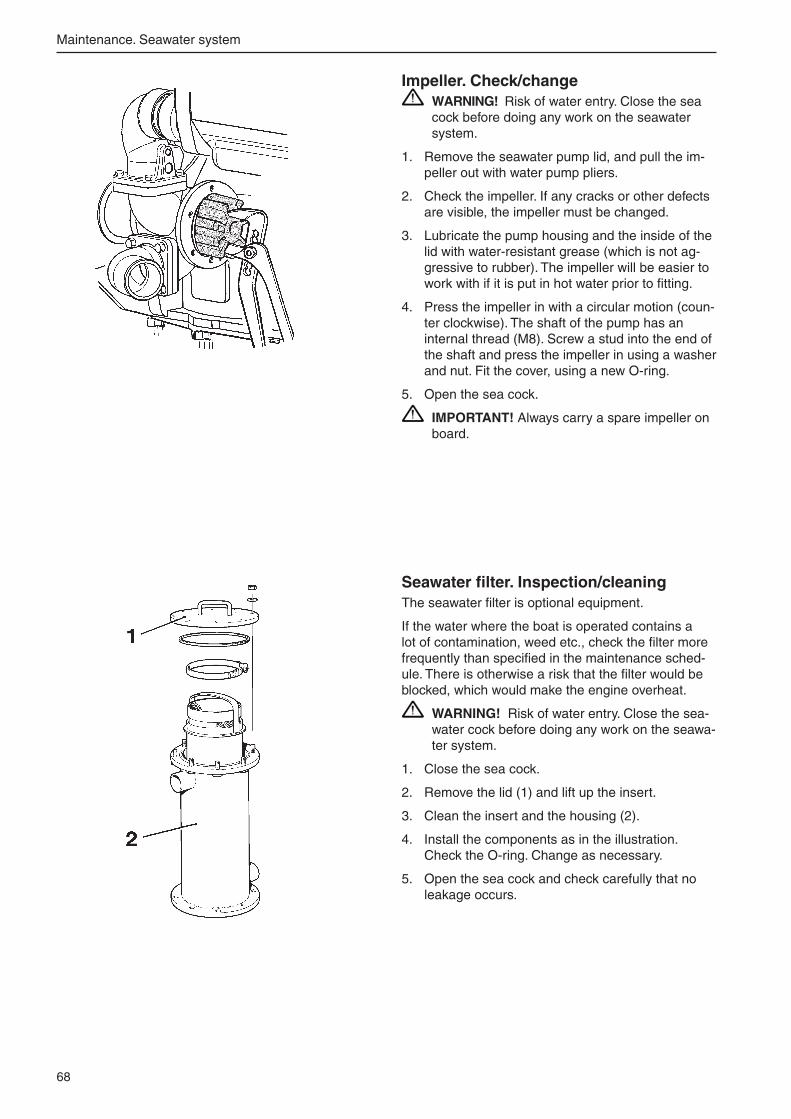
68
Maintenance. Seawater system
Impeller. Check/change WARNING! Risk of water entry. Close the sea
cock before doing any work on the seawater system.
1. Remove the seawater pump lid, and pull the im-peller out with water pump pliers.
�. Check the impeller. If any cracks or other defects are visible, the impeller must be changed.
3. Lubricate the pump housing and the inside of the lid with water-resistant grease (which is not ag-gressive to rubber). The impeller will be easier to work with if it is put in hot water prior to fitting.
4. Press the impeller in with a circular motion (coun-ter clockwise). The shaft of the pump has an internal thread (M8). Screw a stud into the end of the shaft and press the impeller in using a washer and nut. Fit the cover, using a new O-ring.
5. Open the sea cock.
IMPORTANT! Always carry a spare impeller on board.
Seawater filter. Inspection/cleaningThe seawater filter is optional equipment.
If the water where the boat is operated contains a lot of contamination, weed etc., check the filter more frequently than specified in the maintenance sched-ule. There is otherwise a risk that the filter would be blocked, which would make the engine overheat.
WARNING! Risk of water entry. Close the sea-water cock before doing any work on the seawa-ter system.
1. Close the sea cock.
�. Remove the lid (1) and lift up the insert.
3. Clean the insert and the housing (�).
4. Install the components as in the illustration. Check the O-ring. Change as necessary.
5. Open the sea cock and check carefully that no leakage occurs.

69
Maintenance. Seawater system
Inlet manifold. Checking the drain holeWater can condense in the aftercooler during opera-tion. The condensate is drained via a hose connected to a nipple under the rear of the inlet manifold.
Check that the nipple is not blocked.
WARNING! If a large amount of water flows out of the drain hole, from the inlet manifold, the af-tercooler must be removed and proof tested.
This task must be done by an authorised workshop.

70
Maintenance. Fuel system
Fuel system
Only use the grades of fuel recommended in the fuel specification, see Technical Data. Always observe the greatest cleanliness during re-fuelling and work on the fuel system.
All work on the unit injectors of the engine must be carried out by an authorised workshop.
WARNING! Fire hazard. Work on the fuel system must be carried out when the engine is cold. Fuel spills on hot surfaces or electrical components can cause fires. Store fuel-soaked rags and other flammable ma-terial in fireproof conditions.
WARNING! Hot fuel can cause burns.
Fuel system ventingThe fuel system must be vented, e.g. after changing fuel filter, if the fuel tank has been run dry and after long stops.
Single filter and Switchable filters
Stationary engine:1. Put a suitable vessel underneath the fuel filter.
�. Remove the protective cap from the venting nipp-le (1) on the filter bracket. Connect a transparent plastic hose to the nipple and lower this into the vessel.
3. Open the venting nipple and pump up fuel with the hand pump (�) until air-free fuel flows out. Tighten the venting nipple while fuel is flowing out. Repeat with the second switchable filter.
4. Remove the hose and put the protective cap back on the venting nipple.
5. If the tank has been run dry or if the engine, for some reason, has been emptied of fuel, open the venting nipple (3) at the front of the engine block and vent in the same way.
6. Run the engine at idling speed for a couple of minutes to allow any remaining air out of the sys-tem. Then close the vent (3) on the engine and make sure there are no leaks.
1 2 12

71
Maintenance. Fuel system
Fuel filter
Drain WARNING! Hot fuel can cause burns.
Stationary engine:1. Put a suitable vessel underneath the filter.
�. Open the tap (1) and drain water and contamina-tion from the water trap (�) by pumping with the hand pump (3) until clean fuel flows out.
Running engine (switchable filters only):1. Shut off the fuel flow to the filter to be drained (A).
�. Put a suitable vessel underneath the filter.
3. Cautiously open the tap (1).
4. Drain water and contamination from the water trap by turning the handle to venting position (B).Tighten the venting nipple when clean fuel flows out.
5. Repeat with the other filter.
6. Turn the handle to normal operating position (N).
1
2
3
3
2
1

7�
Maintenance. Fuel system
Change the filter elements
Stationary engine:(Single and switchable filters)
1. Close the fuel valve/valves.
�. Clean the filter bracket and put a suitable vessel under the filter.
3. Relieve pressure inside the filter by first opening the drain tap (1) at the bottom of the water trap and then the venting nipple (�) to drain the filter of fuel.
WARNING! High pressure, open the tap with caution. Hot fuel can spray out in any direction.
4. Remove the cables (3) from the water trap (4) and unscrew the water trap from the filter.
5. Unscrew the filter, use a filter wrench if needed.
6. Clean the sealing surfaces of the filter bracket. Make sure the filter is absolutely clean and the sealing surfaces are undamaged. Moisten the sealing rings with engine oil, including the inner rubber seal located inside the threaded hole in the center of the filter.
NOTE! Do not fill the new filter with fuel before assembly. Contaminations may get into the system and cause damage and malfunction.
7. Screw the new filter on by hand until the seal just touches the mating surface. Then tighten a further 1/� turn. Reinstall the water trap and the cables. Close the drain tap.
8. Open the fuel valve.
9. Open the venting nipple and pump up fuel with the hand pump (5) until air-free fuel flows out. Tighten the venting nipple while fuel is flowing out.
10. Remove the hose and put the protective cap back on the venting nipple.
11. Start the engine and check for leakages.
13
2
4
5

73
Maintenance. Fuel system
Change the filter elements
Running engine (switchable filters only):
WARNING! Hot fuel can cause burns.
1. Clean the filter bracket and put a suitable vessel under the filter.
�. Remove the protective cap from the venting nipp-le (1) on the filter bracket. Connect a transparent plastic hose to the nipple and lower this into the vessel.
3. Shut off the fuel flow to one of the filters by lifting the handle (�) and turning it to its end position (A).
4. Remove the cables (3) from the water trap (4) on the shut off filter.
5. Relieve pressure inside the filter by first opening the drain tap (5) at the bottom of the water trap and then the venting nipple to drain the filter of fuel.
WARNING! High pressure, open the tap with caution. Hot fuel can spray out in any direction.
6. Unscrew the water trap and filter, use a filter wrench if needed.
7. Clean the sealing surfaces of the filter bracket. Make sure the filter is absolutely clean and the sealing surfaces are undamaged. Moisten the sealing rings with engine oil, including the inner rubber seal located inside the threaded hole in the center of the filter.
NOTE! Do not fill the new filter with fuel before assembly. Contaminations may get into the system and cause damage and malfunction.
8. Screw the new filter on by hand until the seal just touches the mating surface. Then tighten a further 1/� turn. Reinstall the water trap and the cables. Close the drain tap.
9. Vent by turning the handle (�) to venting po-sition (B). This allows a reduced flow of fuel through the filter and evacuates air through the vent. Tighten the venting nipple when air-free fuel flows out.
10. Remove the hose and put the protective cap back on the venting nipple.
11. Repeat with the other filter.
1�. Turn the handle to normal operating position (N). Check for leakages.
2 1
3
4
5

74
Maintenance. Fuel system
Fuel pre-filter
The fuel pre-filter supplied by Volvo Penta is available in single and twin versions.
Fuel pre-filter. InspectionThis filter is equipped with a pressure gauge (1) which indicates when it is time to change the filter insert.
Change the filer inserts as recommended in the maintenance schedule, or earlier if the pressure gau-ge shows a negative pressure of 6-10 (in. Hg) at idle or 16–�0 (in. Hg) at full speed/loaded engine.
WARNING! Working with, or going close to a running engine is a safety risk. Watch out for ro-tating components and hot surfaces.
Fuel pre-filter. Changing the filter insert The fuel pre-filter/water trap supplied by Volvo Penta is available in single and twin versions. The twin filter inserts can be changed with the engine running, by closing off fuel flow to one filter housing at a time.
Fuel flow is controlled by putting the handle (1) in the following positions:
A: Normal operation (both filters are connected).
B: The left filter insert can be changed.
C: The right filter insert can be changed.
D: Both filters shut off.
DrainPlace a receptacle under the filter. Drain off water and contaminants through the plug (4).
4

75
Maintenance. Fuel system
Change the filter elementsIf the engine is not running close the fuel cocks on the tank before changing filters. If the engine is run-ning cut off the flow of fuel with the handle (1) on the filter itself.
1. Place a receptacle under the filters and shut off the filter to be changed.
�. Undo the T-bolt (�) and remove the cover (3).
3. Take out the insert carefully while turning it.
4. Drain off water and contaminants through the drain plug (4).
5. Fit a new filter insert and fill the container with clean fuel.
6. Change the gasket on the cover and the O-ring on the T-bolt. Moisten the gasket and O-ring with fuel before assembling.
7. Fit the cover and tighten it by hand.
8. Wipe off any fuel from the heat shield.
9. Change the other filter in the same way.
10. Open the fuel cocks and put the handle in posi-tion for normal running. Make sure there are no leaks.

76
Maintenance. Electrical system
Electrical system
The engine is equipped with a �-pole electrical system and an alternator. System voltage is �4V.
WARNING! Before any work is done on the electrical system, the engine must be stopped and the current cut by switching off the battery isolator. Shore current for engine heaters, battery chargers or other auxiliary equipment connected to the engine must be disconnected.
Main switchesThe main switches must never be disconnected before the engine has been stopped. If the circuit between the alternator and the batteries is discon-nected when the engine is running, the alternator and electronics can be damaged. The charging circuits must never be re-connected with the engine running, for the same reason.
IMPORTANT! Never disconnect the current with the main switches when the engine is running.
Electrical connectionsCheck that electrical connections are dry, free from oxide and that they are securely tightened. Spray these connections as necessary with water-repellent spray (Volvo Penta universal oil).

77
Maintenance. Electrical system
Batteries. Maintenance WARNING! Fire and explosion hazard. Batter-
ies must never be exposed to open flames or sparks.
WARNING! Never confuse the positive and negative poles on the batteries. Risk of arcing and explosion.
WARNING! Battery electrolyte is highly corro-sive. Always protect your eyes, skin and clothes when handling batteries. Always use protective goggles and gloves. If acid comes into contact with your skin, wash at once with soap and a lot of water. If you get battery acid in your eyes, flush at once with a lot of water, and get medical assistance at once.
Connection and disconnectionWhen you connect batteries, first connect the + cable (red) to the + pole on the battery. Then connect the – cable (black) to the – pole on the battery
When you disconnect batteries, disconnect the – ca-ble (black) first, then the + cable (red).
CleaningKeep the batteries dry and clean. Contamination and oxide on the batteries and battery poles can cause stray currents, voltage drop and discharge, especially in wet weather. Clean oxidation from the battery poles and terminals, using a copper brush. Tighten the terminals securely and grease them with terminal grease or Vaseline.
Electrolyte levelThe electrolyte level should be 5–10 mm (0.�–0.4”) above the cell plates in the battery. Top up with bat-tery water as necessary. After topping up, the bat-teries should be charged by connecting them to a battery charger, or by running the engine at normal speed for 30 minutes.
NOTE! Some maintenance-free batteries have spe-cial instructions, which must be observed.
IMPORTANT! Never confuse the positive and negative poles on the batteries.

78
Maintenance. Electrical system
Batteries. Charging WARNING! Explosion risk! Hydrogen is given
off when batteries are charged. This forms an explosive mixture with air. A short circuit, open flame or spark could cause a violent explosion. Ventilate well.
WARNING! Battery electrolyte is highly corro-sive. Protect your eyes, skin and clothes. Always use protective goggles and gloves. If acid comes into contact with your skin, wash at once with soap and a lot of water. If you get battery acid in your eyes, flush at once with a lot of water, and get medical assistance at once.
Charge batteries if they have become discharged. If the boat is not used for a longer period of time, the batteries should be fully charged, then trickle charged (please refer to the battery manufacturer’s recommendations). Batteries are damaged by being left discharged, and can also freeze and burst easier in cold weather.
IMPORTANT! Observe the instruction manual for the battery charger carefully. To avoid the risk of electrochemical corrosion when an external charger is connected, the battery cables in the boat should be removed from the batteries be-fore the charger is connected.
During charging, unscrew the cell plugs but leave them in the plug holes. Ventilate well, especially if the batteries are charged in an enclosed space.
WARNING! Always switch off the charge cur-rent before undoing the charging clamps. Never confuse the positive and negative poles on the batteries. Risk of arcing and explosion.
Special instructions apply to so-called quick char-gers. Quick charging can shorten battery life, and should therefore be avoided.

79
Maintenance. Electrical system
Electric weldingRemove the positive and negative cables from the batteries. Then disconnect all cables connected to the alternator.
Also undo the two connectors for the EVC system from the control unit. Press the lock tab down and pull the connector out.
Always connect the welder earth clamp to the compo-nent to be welded, and as close as possible to the weld site. The clamp must never be connected to the engine or in such a way that current can pass through a bear-ing.
IMPORTANT! After you have finished welding, re-connect the EVC connector and the alterna-tor terminals before you connect the battery cables.
Electrical installationsAn incorrectly done electrical installation can gener-ate stray currents from the electrical system. Stray currents, in their turn, can weaken the galvanic pro-tection of the propeller, propeller shaft, rudder, keel etc., and cause damage because of electrochemical corrosion.
IMPORTANT! Work on the low voltage circuits in the boats should be done by a person with electrical training or knowledge. Installation or work on land current equipment must only be done by a competent electrician, in accordance with local regulations for mains electricity.
Always consider the following:
1. If land current is connected, its protective earth must be connected ashore, never to the boat. The land current installation must also be provided with an earth fault breaker (RCCB). The land current installation (transformer, inverter, battery charger etc. ) must be intended for marine use, where the high voltage section is galvanically isolated from the low voltage section.
�. Electrical cables must be installed and clamped in such a way that they are not exposed to chaf-ing, damp or splashing water in the bilge.

80
Maintenance. Electrical system
1
3. Protective earth cables for radio, navigation equipment, rudder, bathing steps etc., or other equipment which uses protective earthing, shall be connected to a common earthing point which is not connected to the engine or reverse gear.
IMPORTANT! The engine and reverse gear must never be used as earth planes.
4. The starter battery shall have a main switch on the positive (+) side of the battery. The main switch must disconnect all loads and shall be switched off when the boat is not used.
5. If an extra auxiliary battery is used, a main switch (1) must be connected between the auxiliary battery positive (+) pole and the fuse box for the boat’s electrical equipment. The main switch must disconnect all loads connected to the auxiliary battery and shall be switched off when the loads are not used. All equipment connected to the aux-iliary battery shall have separate switches.
A charge splitter (optional) should be installed to charge two independent battery circuits from the standard alternator.

81
Maintenance. Reverse gear
Reverse gear
Oil level. Checking and fillingInspectionCheck the oil level when the reverse gear has reached operating temperature, with the engine idling and the control lever in neutral.
WARNING! Working with, or going close to a running engine is a safety risk. Watch out for ro-tating components and hot surfaces.
Remove the dipstick (1), wipe it off and put it back into the reverse gear. Remove the dipstick again and check the oil level. The correct oil level is between the MAX and MIN marks.
FillingIf necessary, top up with oil through the filler hole (�) on top of the reverse gear. Oil grade and volume: Please refer to the “Technical Data” chapter.
IMPORTANT! Never over-fill the reverse gear. The oil level must always be within the recom-mended range.
Oil strainer. Cleaning WARNING! Working with, or going close to a
running engine is a safety risk. Watch out for ro-tating components and hot surfaces.
1. Remove the lid/plug and carefully remove the strainer (1) from the housing.
IMPORTANT! Cleanliness! Dirt must not be allowed to get into the reverse gear.
�. Clean the strainer and other components in pa-raffin (kerosene).
3. Carefully put the components back again.
4. Tighten the plug/screw.
5. Start the engine and check carefully that no lea-kage occurs
1

8�
Maintenance. Reverse gear
Oil. Change 1. Remove the dipstick. Connect a hose from the oil
scavenging pump to the dipstick tube.
�. Suck the oil up and put the dipstick back.
3. Fill up with oil to the correct level. Oil grade and vol-ume: Please refer to the “Technical Data” chapter.
IMPORTANT! Never over-fill the reverse gear.
4. Start the engine and run until the reverse gear has reached operating temperature.
5. Check the oil level, as in the description on the previous page.
Seal. Lubrication
Applies only to TwinDisc reverse gearLubricate theseal on the output shaft bearing (with the lubricating nipple) using a hand gun and lithium-based grease such as Mobilux EP�, Statoil Uniway EP�N, Texaco Multifak EP�, Q8 Rembrandt EP�.

83
Maintenance: Accessories
Disengageable clutch. AdjustingStop the engine and put the clutch lever in neutral. Remove the inspection hatch and turn the clutch until the locking device on the adjusting ring is accessible. The locking devices have slightly different appearanc-es depending on the make (see illustrations).
Twin Disc (T.D.)1. Press the locking pin (A) and turn the adjusting ring
(B) to the right enough notches so that a torque of �18 Nm (161 lbf.ft.) is required on the lever for en-gagement.
�. Screw on the inspection hatch.
Accessories
Disengageable clutch. LubricationUse lithium-based grease such as Mobilux EP�, Statoil Uniway EP�N, Texaco Multifac EP�, Q8 Rem-brandt EP�.
Main bearing and clutch mechanismLubricate the inner support bearing (with lubricat-ing nipple), the main bearings, release shaft and the moving parts in the clutch mechanism with grease. Lubricate sparingly, �0–30 grams (0.6–1.0 oz ) for the main bearings. Lubricate the inner link arms with a few drops of oil.
Release bearingLubricate sparingly so the grease is not forced out. Use grease complying with the recommendations above.
IMPORTANT! If operated more than 15–�0 times a day, the release bearing must be lubri-cated every 50 operating hours. Otherwise, every 500 operating hours.

84
Laying up/LaunchingThe boat must be laid up to prevent damage to the engine and other equipment if the boat is not used for two months or more. It is important that this is done in the correct manner, and nothing is forgotten. For this reason, we have compiled a check list of the most important points.
Before the boat is taken out of service for a long period of time, an authorised Volvo Penta workshop should over the engine and other equipment. Have any faults and deficiencies attended to, so that the equipment is in order, ready for the next start.
WARNING! Before you start to do any maintenance work, read the “Maintenance” chapter carefully. This contains instructions for doing work in a safe and correct manner.
Some conservation oils are flammable. Some are also dangerous to breathe. Ensure good ventilation. Use a face mask when spraying.
IMPORTANT! Observe the following when cleaning with a high pressure washer: Never aim the water jet at seals, rubber hoses or electrical components. Never use a high pressure washer for engine cleaning.
Inhibiting● Warm the engine up to normal operating tem-
perature and check that the oil level in the reverse gear reaches the MAX mark on the dipstick. Stop the engine.
● Max 8 month’s stoppage: Change the oil and oil filter on the engine, then warm it up afterwards.
● More than 8 month’s stoppage: Conserve the lubrication and fuel systems with conservation oil.Please refer to the instruction on the next page.
● Check that the coolant offers sufficient frost pro-tection. Top up as necessary. Alternatively, you can drain the coolant (also drain the coolant fil-ter).
● Close the sea cock and drain the water from the seawater system.
● Remove the impeller from the seawater pump. Store the impeller in a sealed plastic bag, in a cool place.
● Drain any water and contamination from the fuel filters and fuel tank. Fill the fuel tank completely, to avoid condensation.
● Disconnect the battery cables, clean and charge the batteries. Trickle charge the batteries while the boat is laid up. A poorly charged battery can freeze and burst.
● Clean the outside of the battery. Do not use a high pressure washer for engine cleaning. Touch up paint damage with Volvo Penta original paint.
● Spray the components of the electrical system with water-repellent spray (Volvo Penta universal oil).
● Check and rust-proof any control cables.
● Put a note on the engine with the date, type of conservation and the conservation oil used.
● Cover over the engine air inlet, exhaust opening and engine if necessary.

85
Laying up/Launching
Bringing out of storage● Remove any covers from the engine, air inlet and
exhaust pipe.
● Top the engine up with the correct grade of oil, if necessary. Install a new oil filter if the filter was not changed during conservation.
● Check that there is oil in the reverse gear.
● Install new fuel filters and vent the fuel system.
● Check the drive belt(s).
● Check the condition of all rubber hoses, and re-tighten the hose clamps.
● Close the drain taps and install the drain plugs.
● Insert the impeller in the seawater pump, using a rotating movement (anti-clockwise).
● Check the coolant level and anti-freeze. Top up as necessary.
● Connect the fully charged batteries.
● Open the sea cocks
● Start the engine (if the boat is in the water) and warm up at a fast idle before loading the engine.
● Check that no oil, fuel or coolant leakage occurs.
● Check the oil level in the reverse gear. Top up as necessary.
Conservation of the lubrication and fuel systems for more than 8 months’ stoppage:
● Drain the oil from the sump and engine and fill the engine up with conservation oil* to just above the MIN marking on the dipstick.
● Connect the fuel supply (1) and return fuel pipes (�) to a jerrican filled with 1/3 conserva-tion oil* and �/3 diesel fuel.
● Vent the fuel system.
● Start the engine and run at a fast idle until about � litres (0.5 US gal.) have been used. Stop the engine and connect the ordinary fuel pipes.
● Empty the conservation oil out of the engine
● Follow the other instructions on the previous page.
* Conservation oils are sold by oil companies.

86
In case of emergency Despite regular maintenance according to the maintenance schedule and perfect operation, it may occur that a fault occurs which must be attended to before the boat can travel further. This chapter contains tips for rectifying some of the possible faults.
There are safety functions which are activated when certain faults occur, to protect the engine. The following can occur:
● Engine can not be started
● Reversing gear in neutral and engine speed is limited to 1000-1�00 rpm, depending on engine.
● The engine stops
If fault occurs, acknowlege any alarm and take the recommended measures. Please refer to this chapter and the “Fault register” chapter.
Starting with auxiliary batteries WARNING! Ventilate well. Batteries contain and
give off an explosive gas which is highly flam-mable and explosive. A short circuit, open flame or spark could cause a violent explosion.
WARNING! Never confuse the positive and ne-gative poles on the batteries. Risk of arcing and explosion.
1. Check that the rated voltage of the help start battery is the same as the system voltage of the engine.
�. Connect the red jumper cable to the positive pole (+) of the flat battery, and then to the positive pole of the help start battery.
3. Connect the black jumper cable to the negative pole (–) of the help start battery, and then to a place some distance from the flat batteries, such as the negative connection on the starter motor.
WARNING! Under no circumstances may the black jumper cable (–) come into contact with the positive connection on the starter motor.
4. Start the engine and run at a fast idle for about ten minutes to charge the batteries.
WARNING! Working with, or going close to a running engine is a safety risk. Watch out for ro-tating components and hot surfaces.
WARNING! Do not touch the connections during the start attempt: Risk of arcing. Do not stand bending over any of the batteries either.
5. Stop the engine. Remove the jumper cables in the exact reverse order from installation.

87
In case of emergency
Emergency shiftingIf a fault occurs which prevents the revers gear from being operated (shifted) with the control lever, it is possible to shift manually, using the description be-low.
Note. The descriptions refer to electrically shifted revers gear.
WARNING! In emergency shifting, the unit is locked in forwards operation. Please note that the revers gear can not then be disengaged with the control lever. Forward motion can only be cut off by stopping the engine with the igni-tion key or stop button.
1. Stop the engine and remove the start key from the key switch.
�. Note the valve (P or S) to which the cable marked “Primary” is connected. Then undo the connec-tors (1 and �) from the solenoid valves.
3. Remove the cap nut from the valve which was connected to the “Primary” cable.
4. Press the valve (A) on the valve.
5. Turn the button a 1/� turn anti-clockwise (the button is forced out by spring action). The reverse gear is now connected for forward motion and cannot be disengaged by the control lever.
12
A

88
In case of emergency
Fault-tracingA number of symptoms and possible causes of engine malfunctions are described in the table below. Always contact your Volvo Penta dealer if problems occur which you can not solve by yourself.
WARNING! Read through the safety advice for care and maintenance work in the “Safety information” chapter before starting work.
1. Flat batteries �. Poor contact/open circuit in cables 3. Main switch turned off 4. One of the circuit breakers in the distri-
bution box has tripped. 5. Faulty key switch 6. Control lever not in neutral/control po-
sition not activated 7. Faulty stop relay 8. Faulty main relay 9. Faulty starter relay 10. Faulty starter motor relay 11. Faulty starter motor/solenoid 1�. Lack of fuel: – fuel taps closed – fuel tank empty/wrong tank con-
nected 13. Blocked fine fuel filter/pre-filter (caused by contamination or fuel strati-
fication at low temperature)
14. Air in the fuel system 15. Water/contamination in fuel 16. Boat abnormally loaded 17. Fouling on hull/propeller 18. Faulty injectors (nozzles) 19. Insufficient air supply to engine: – blocked air filter – air leakage between turbocharger
and engine inlet pipe. – fouled compressor section in turbo-
charger – faulty turbocharger – poor engine bay ventilation �0. Excessive coolant temperature �1. Too low coolant temperature ��. Too low oil level �3. Faulty / wrong propeller �4. Faulty engine mounting �5. Coolant level too low
�6. Air in the freshwater system �7. Faulty circulation pump �8. Closed seawater inlet �9. Blocked seawater inlet/pipe/filter 30. Defective impeller in seawater pump 31. Defective thermostat 3�. Blocked heat exchanger insert 33. Blocked aftercooler 34. Too high oil level 35. Alternator drive belt slips 36. Water entry into engine 37. High back pressure in exhaust system 38. Stored fault codes* 39. Check that the emergency stop button
is in the running position (not pressed down).
* NOTE! The codes can only be read and erased by a service technician.
Symptoms and possible causes
Pop-ups are shown in the tachometer display See the “Fault register” chapter
Engine can not be stopped �, 4, 5, 7
Starter motor does not rotate 1, �, 3, 4, 5, 6, 8, 9, 10, 11, 36, 38, 39
Starter motor rotates slowly 1, �
Starter motor rotates normally but engine does not start 1�, 13, 14, 15, 38
Engine starts but stops again 1�, 13, 14, 15, 19, 38
Engine does not reach full operating speed at full throttle 13, 14, 15, 16, 17, 18, 19, �0, �3, 33, 37, 38
Engine runs unevenly 14, 15
Engine vibrates �4
High fuel consumption 16, 17, �1
Black exhaust smoke 19
Blue or white exhaust smoke �0, �1, 34
Lubrication oil pressure too low ��
Coolant temperature too high �5, �6, �7, �8, �9, 30, 31, 3�
Coolant temperature too low 31
No charge or poor charge �, 35

89
In case of emergency
Diagnostic functionThe diagnostic function monitors and checks that the engine, stern drive/reverse gear and EVC system function normally.
The diagnostic function has the following tasks:
● Discover and localize malfunctions
● Notify that malfunctions have been discovered
● Give advice in fault finding
● Protect the engine and ensure continued operation when serious malfunctions are discovered.
The diagnostic function affects the engine in the following ways when:
1. The diagnostic function has discovered a minor malfunction which does not damage the engine.
Reaction: The engine is not affected.
�. The diagnostic function has discovered a serious malfunction which will not immediately damage the engine (e.g. high coolant temperature):
Reaction: Engine power is reduced till the rele-vant value is normalized.
3. The diagnostic function has discovered a serious malfunction which will cause serious engine da-mage.
Reaction: Engine power is reduced.
4. The diagnostic function has discovered a serious malfunction which makes it impossible to control the engine.
Reaction: The reversing gear/drive is disengaged and engine speed is cut to 1000 rpm.
It is possible to do an emergency shift: Please re-fer to the “Emergency shifting” section.
5. The diagnostic function has discovered a serious malfunction on the sterndrive shift mechanism or in the engine fuel injection system.
Reaction: Engine is stopped
It is possible to do an emergency shift: Please re-fer to the ”Emergency shifting” section. In serious emergency it is also possible to start the engine with gear engaged after acknowledging the alarm.

90
In case of emergency
Malfunction message engine and EVC-systemIf the diagnostic function discovers a malfunction, it warns the driver by showing pop-ups in the tachome-ter display and the buzzer will sound.
Pop-ups will alternate between “cause of fault” and “measures to take”.
To acknowledge the alarm, press NAVIGATION WHEEL. When the fault has been acknowledged, the buzzer will become silent. Press NAVIGATION WHE-EL. The pop-up will disappear and normal display window will be shown.
NOTE! To enable engine start the alarm must be ack-nowledged.
Danger pop-upIf the Danger pop-up is shown during operation, a serious fault has occured.
NOTE! Acknowledge the alarm and stop the engine at once.
Information regarding “cause of fault” and “measures to take” is found in chapter “Fault register”.
Warning pop-upIf the Waring pop-up is shown during operation, a fault has occured.
NOTE! Acknowledge the alarm and stop the engine at once.
Information regarding “cause of fault” and “measures to take” is found in chapter “Fault register”.
Caution pop-upIf the Caution pop-up is shown during operation, a fault has occured.
Acknowledge the alarm.
Information regarding “cause of fault” and “measures to take” is found in chapter “Fault register”.
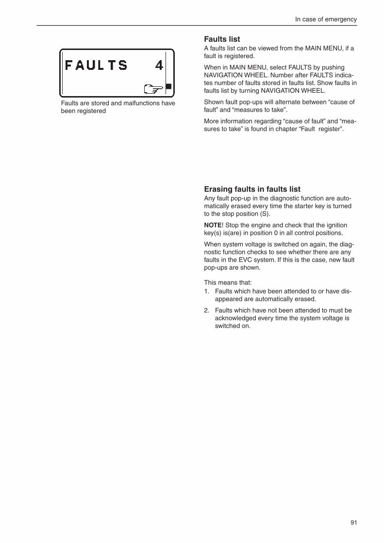
91
In case of emergency
Faults are stored and malfunctions have been registered
Faults listA faults list can be viewed from the MAIN MENU, if a fault is registered.
When in MAIN MENU, select FAULTS by pushing NAVIGATION WHEEL. Number after FAULTS indica-tes number of faults stored in faults list. Show faults in faults list by turning NAVIGATION WHEEL.
Shown fault pop-ups will alternate between “cause of fault” and “measures to take”.
More information regarding “cause of fault” and “mea-sures to take” is found in chapter “Fault register”.
Erasing faults in faults listAny fault pop-up in the diagnostic function are auto-matically erased every time the starter key is turned to the stop position (S).
NOTE! Stop the engine and check that the ignition key(s) is(are) in position 0 in all control positions.
When system voltage is switched on again, the diag-nostic function checks to see whether there are any faults in the EVC system. If this is the case, new fault pop-ups are shown.
This means that: 1. Faults which have been attended to or have dis-
appeared are automatically erased.
�. Faults which have not been attended to must be acknowledged every time the system voltage is switched on.

9�
Engine speed R
Explanation: Fault in engine speed sensor. Reaction: Engine power is reduced.
Action:
• Please contact a Volvo Penta workshop.
Water in fuel O
Explanation: Water in water trap in fuel filters.Reaction: None
Action:
• Empty the water trap underneath the fuel filters, please refer to Please refer to “Maintenance: Fuel system”.
• Please contact a Volvo Penta workshop if the fault remains.
Seawater pressure R
Explanation: Seawater pressure too low. Reaction: Engine power is reduced.
Action:
• Check that the seawater filter is not blocked. Please refer to "Maintenance: Seawater system".
• Check the impeller in the sea water pump. Please refer to “Maintenance: Seawater system”.
• Check that no leakage occurs.
• Please contact a Volvo Penta workshop if the fault remains.
Fault register
Description R
Explanation: Reaction:
Action:
WARNING! Read the safety precautions for maintenance and service in the ”Safety information” chapter before starting work.
ExplanationFaults are presented with information about reason and proposed measures to be taken.
1. 3.2.
1. Description of current fault and measures to take.
�. Current warning lamp which flashes during an alarm. O/R means that an orange or red lamp flashes.
3. Audible warning
4. Current fault pop-up which is shown on the EVC tachometer display.
4.

93
Fault register
Air temperature R
Explanation: Charge air temperature too high.Reaction: Engine power is reduced.
Action:
• Please contact a Volvo Penta workshop.
Coolant level R
Explanation: Coolant level too low. Reaction: Engine power is reduced.
Action:
• Check coolant level. Please refer to "Maintenance: Freshwater system".
• Check that no leakage occurs in auxiliary equipment connected to the engine cooling system.
• Please contact a Volvo Penta workshop if the fault remains.
Coolant pressure R
Explanation: Coolant pressure too low. Reaction: Engine power is reduced.
Action:
• Check the coolant level. Please refer to "Maintenance: Freshwater system".
• Check that the seawater filter is not blocked. Please refer to “Maintenance: Seawater system”.
• Check the impeller in the seawater pump. Please refer to “Maintenance: Seawater system”.
• Check that no leakage occurs.
• Check that no leakage occurs in auxiliary equipment connected to the engine cooling system.
• Please contact a Volvo Penta workshop if the fault remains.
Coolant temperature R
Explanation: Ccoolant temperature too high.
Reaction: Engine power is reduced.
Action:
• Check coolant level. Please refer to “Maintenance: Fresh water system”.
• Check that the seawater filter is not blocked. Please refer to “Maintenance: Seawater system”.
• Check the impeller in the seawater pump. Please refer to “Maintenance: Seawater system”.
• Check that no leakage occurs.
• If the cooling water flow ceases, the exhaust hose should be inspected internally and replaced if the hose shows signs of damage.
• Please contact a Volvo Penta workshop if the fault remains.

94
Fault register
Fuel pressure R
Explanation: Fuel pressure too low. Reaction: Engine power is reduced.
Action:
• Check the fuel level.
• Open the fuel taps and check that no leakage occurs.
• Check that the fuel filters are not blocked. Please refer to “Maintenance: Fuel system”
• Please contact a Volvo Penta workshop if the fault remains.
Fuel temperature R
Explanation: Fuel temperature too high. Reaction: Engine power is reduced.
Action:
• Check the fuel level.
• Check fuel cooler.
• Check that no leakage occurs.
• Please contact a Volvo Penta workshop if the fault remains.
Engine oil level R
Explanation: Oil level too low.
NOTE! In rough following seas or head seas, the system can incorrectly sense that the engine oil level is too low. If this happens, acknowledge the fault, and check the points below for safety reasons.
Reaction: Engine power is reduced.
Action:
• Check the oil level in the engine. Please refer to "Maintenance: Lubrication system" to check and top the oil up.
• Check the oil filters. Please refer to "Maintenance: Lubrication system".
• Check that no leakage occurs.
• Please contact a Volvo Penta workshop if the fault remains.
Engine oil pressure R
Explanation: Oil pressure too low. Reaction: Engine power is reduced.
Action:
• Check the oil level in the engine. Please refer to “Maintenance: Lubrication” to check and top the oil up.
• Check that the oil filters are not blocked.
• Check that no leakage occurs.
• Please contact a Volvo Penta workshop if the fault remains.

95
Fault register
Engine oil temperature R
Explanation: Engine oil temperature too high.
Reaction: Engine power is reduced.
Action:
• Check the oil level. Please refer to "Maintenance: Lubrication system".
• Check that the oil filters are not blocked. Please refer to "Maintenance: Lubrication system".
• Check that no leakage occurs.
• Please contact a Volvo Penta workshop if the fault remains.
Engine oil filter R
Explanation: Oil pressure differential too big. Reaction: Engine power is reduced.
Action:
• Check that the oil filters are not blocked. Please refer to "Maintenance: Lubrication system”.
• Please contact a Volvo Penta workshop if the fault remains.
Crankcase pressure R
Explanation: Crankcase pressure too high. Reaction: Engine power reduced.
Action:
• Check that the crankcase ventilation is not blocked. Please refer to “Maintenance: Engine, general”.
• Please contact a Volvo Penta workshop if the fault remains.
Exhaust temperature R
Explanation: Exhaust temperature too high. Reaction: Engine power is reduced.
Action:
• Please contact a Volvo Penta workshop.
Transmission oil pressure R
Explanation: Transmission oil pressure too low. Reaction: Engine power is reduced.
Action:
• Check oil level. Please refer to “Maintenance: Lubrication system”.
• Check that the oil strainer is not blocked. Please refer to “Maintenance: Lubrication system”.
• Check that no leakage occurs.
• Please contact a Volvo Penta workshop if the fault remains.

96
Fault register
Battery voltage O
Explanation: Battery voltage too low. Reaction:
Action:
• Check battery fluid level.
• Check belt tension.
• Please contact a Volvo Penta workshop if the fault remains.
Auxiliary stop R
Explanation: External stop signal. Reaction: Engine stops or can not be started
Action:
• Check emergency stop button. Reset if necessary. Please refer to "Stopping the engine: Emergency stop"
• Please contact a Volvo Penta workshop if the fault remains.
Primary battery R
Explanation: Poor battery or charging. Reaction:
Action:
• Check battery fluid level.
• Check belt tension.
• Please contact a Volvo Penta workshop if the fault remains.
Secondary battery R
Explanation: Poor battery or charging. Reaction:
Action:
• Check battery fluid level.
• Check belt tension.
• Please contact a Volvo Penta workshop if the fault remains.
30 V supply fuse R
Explanation: Fuse is broken. Reaction:
Action:
• Please contact a Volvo Penta workshop.

97
Fault register
EMS supply fuse R
Explanation: Fuse is broken. Reaction:
Action:
• Please contact a Volvo Penta workshop.
Extra supply fuse R
Explanation: Fuse is broken. Reaction:
Action:
• Please contact a Volvo Penta workshop.
Check control lever O/R
Explanation: Fault in control lever. Reaction: Engine in emergency mode. Gear to neutral.
Action:
• Restart engine(s).
• If the engine can not be operated from the chosen control panel, use an alternative control panel.
• Please contact a Volvo Penta workshop if the fault remains.
Lever calibration O
Explanation: Incorrect lever calibration. Reaction: It is not possible to choose active helm station.
Action:
• Restart engine(s).
• Please contact a Volvo Penta workshop if the fault remains.
Check EVC system O/R
Explanation: Internal fault in the EVC system. Reaction: Engine power is reduced.
Action:
• Restart engine(s).
• If the engine can not be operated from the chosen control panel, use an alternative control panel.
• Please contact a Volvo Penta workshop if the fault remains.

98
Fault register
System failure R
Explanation: Miscellaneous fault. Reaction:
Action:
• Restart engine(s).
• Please contact a Volvo Penta workshop if the fault remains.
Check joystick O/R
Explanation: Fault in joystick. Reaction: Engine power is reduced.
Action:
• Restart engine(s).
• If the engine can not be operated from the chosen control panel, use an alternative control panel.
• Please contact a Volvo Penta workshop if the fault remains.
Check steering wheel O
Explanation: Fault in steering wheel unit. Reaction: Engine power is reduced.
Action:
• Restart both engines.
• Please contact a Volvo Penta workshop if the fault remains.
Limited engine rpm R
Explanation: Fault in steering system. Reaction: Engine power is reduced on both sides.
Action:
• Restart both engines.
• Please contact a Volvo Penta workshop if the fault remains.
Limited steering R
Explanation: Fault in steering system. Reaction: Engine power is reduced on both sides. Limited steering.
Action:
• Restart both engines.
• Please contact a Volvo Penta workshop if the fault remains.

99
Fault register
No steering wheel response R
Explanation: Fault in steering wheel unit. Reaction: Engine power is reduced on both sides. No steering.
Action:
• Restart both engines.
• Please contact a Volvo Penta workshop if the fault remains.
No gear/throttle and steering R
Explanation: Fault in steering system. Reaction: No steering. No propulsion.
Action:
• Restart both engines.
• Please contact a Volvo Penta workshop if the fault remains.

100
Technical data
Fuel system
Fuel specification The fuel must comply with national and international standards for commercially supplied fuels, such as:
EN 590 (with national environment and cold requirements)ASTM D 975 No 1-D and 2-DJIS KK 2204Sulfur content: Complying with legal requirements in each country.
Low density fuel (urban diesel in Sweden and city diesel in Finland) can cause a loss of up to 5% of power and an increase in fuel consumption of about �–3%.
Engine modelEngine model ...................................................... D12-300 D12-350 D12-400 Crankshaft power @ 1800 rpm, kW (hp) ........... �16 (�94) �56 (348) �94 (400)
Max. torque @ 1000 rpm, Nm (lbf.ft) .................. 1461 (1078) Max. torque @ 1�00 rpm, Nm (lbf.ft) .................. 159� (1174) 1814 (1338)Max. torque @ 1400 rpm, Nm (lbf.ft) ..................
Engine model ...................................................... D12-450 D12-500 D12-550 Crankshaft power @ 1800 rpm, kW (hp) ........... 331 (450) 367 (499)
Crankshaft power @ 1900 rpm, kW (hp) ........... 405 (550) Max. torque @ 1�00 rpm, Nm (lbf.ft) .................. ��04 (16�6) �196 (16�0) Max. torque @ 1400 rpm, Nm (lbf.ft) .................. �019 (1489)
GeneralAfter market designation .......................................... D1�D-C MHNo. of cylinders and configuration ............................. in-line 6Bore/stroke ............................................................... 131/150 mm (5.16/5.91in) Displacement ............................................................ 1�.13 l (740 in3) Compression ratio .................................................... 17.5:1 Dry weight bobtail ..................................................... 1400 kg (3086 lb)Dry weight with reverse gear MG5114SC ................ 1603 kg (3534 lb)Low idle speed .......................................................... 5�5 (±10) rpm** At delivery, the idling speed is adjusted to 5�0 rpm. If needed, the speed can be adjusted within the range 550–700 rpm (refer to page ).
Technical data according to ISO 8665.

101
Technical data
SAE5W/30
−−−−−30 −−−−−20 −−−−−10 ±0 +10 20 30 40
−−−−−22 −−−−− 4 +++++14 32 50 68 86 104
−−−−−15oC SAE15W/40
−−−−−25oC SAE10W/30
−−−−−10oC SAE20W/30
±0oC SAE30
SAE40+10oC
oC
oF
✱✱✱✱✱
Lubricating systemOil capacity including oil filters, approx., no engine inclination ......................................... 56 liters (11.6 US gals)
Oil pressure, hot engine, at normal running rpm ...................................... 400–550 kPa (57–80 psi) at idling rpm (min.) ........................................... 175 kPa (�5.3 psi)Oil grade .............................................................. Refer to specification on page 57
Viscosity at different outside air temperatures(Temperature based on constant outside airtemperature.
* Refers to synthetic or semi-synthetic oil.
Cooling systemFreshwater system capacity including heatexchanger, approx. .............................................. 60 liters (15.9 US gals)
Electrical systemSystem voltage .................................................... �4VAC generator, voltage/max. amperage .................................... �8V/60A output, approx. .................................................. 1700WAlternative generator equipment (accessory): voltage/max. amperage .................................... �8V/100A output, approx. .................................................. �800WAlternative generator equipment (accessory): voltage/max. amperage .................................... 14V/130A output, approx. .................................................. 18�0W Battery capacity ................................................... � connected in series 1�V, max. 15�Ah Battery electrolyte density at +�5°C (77°F): fully charged battery ......................................... 1.�8 g/cm3 = 0.046� lb/in3 (1.�4 g/cm3 = 0.0448 lb/in3 )* battery recharged at ......................................... 1.�4 g/cm3 = 0.0448 lb/in3 (1.�0 g/cm3 = 0.0434 lb/in3 )*
* Note. Applies to batteries with tropical acid.
10�
Technical data
Reverse gearTwin DiscType designation MG5114SC MG5114DC
Oil capacity, approx.. ................................................ 13 liters (3.4 US gals) 19,7 liters (5.� US gals)
Oil grade (in accordance with API system) .............. CC, CD, CE CC, CD, CE
Viscosity at oil temperature 66–85°C ...................... SAE30* SAE30*
Viscosity at oil temperature 85–100°C .................... SAE40* SAE40*
Oil pressure during ** Neutral ................................. 0,�07–0,634 MPa 0,�07–0,634 MPa
(�,1–6,5 kp/cm�) (�,1–6,5 kp/cm�)
Oil pressure during ** operation ............................ 1,57–1,63 MPa 1,57–1,63 MPa
(16–16,6 kp/cm�) (16–16,6kp/cm�)
Weight, approx. ........................................................ �13 kg (470 lbs) 374 kg (8�5 lbs)
* NOTE! Only single grade lubricating oil (only one viscosity number) may be used in the reverse gear.
** At oil temperature 8�°C and 1800 rpm.
ClutchDisengageable clutches at front of engine (accessory)Twin Disc
Type ......................................................................... Twin disc clutch (“over-center” type)
Gear ratio ................................................................. 1:1
Size .......................................................................... �9� mm (11 ½”)
Permitted engine speed with PTO engaged ............ 900–1800 rpm.
Max. permitted torque output ................................... 514 Nm (379 lbf.ft.)
Weight, approx. ........................................................ 78 kg (17� lbs)

Notes
...........................................................................................................................................................................................
...........................................................................................................................................................................................
...........................................................................................................................................................................................
...........................................................................................................................................................................................
...........................................................................................................................................................................................
...........................................................................................................................................................................................
...........................................................................................................................................................................................
...........................................................................................................................................................................................
...........................................................................................................................................................................................
...........................................................................................................................................................................................
...........................................................................................................................................................................................
...........................................................................................................................................................................................
...........................................................................................................................................................................................
...........................................................................................................................................................................................
...........................................................................................................................................................................................
...........................................................................................................................................................................................
...........................................................................................................................................................................................
...........................................................................................................................................................................................
...........................................................................................................................................................................................
...........................................................................................................................................................................................
...........................................................................................................................................................................................
...........................................................................................................................................................................................
...........................................................................................................................................................................................
...........................................................................................................................................................................................
...........................................................................................................................................................................................
...........................................................................................................................................................................................

104
NB! This offer is valid for a period of 12 months from delivery of the boat. Availability after this period will be as far as supplies admit.
Post or fax this coupon to:Document & Distribution CenterOrder DepartmentARU�, Dept. 646�0SE-405 08 GöteborgSwedenFax: +46 31 545 77�
Orders can also be placed via the Internet:http://www.volvopenta.com/manual/coupon
Yes please,I would like an operator’s manual in English at no charge.
Publication number: 7746214
Name
Address
Country 4��0
0/61
5001
/155
0999
0019
�
✂
Bitte beachten Sie, dass dieses Angebot für die Dauer von 12 Monaten ab dem Lieferdatum des Bootes gilt, danach bis zum Aufbrauchen des Lagerbestandes.
Schicken Sie den Coupon per Post oder als Fax an:Document & Distribution CenterOrder DepartmentARU�, Dept. 646�0SE-405 08 GöteborgSchwedenFax: +46 31 545 77�
Die Bestellung kann auch über das Internet erfolgen:http://www.volvopenta.com/manual/coupon
Ja,ich will kostenlos eine Betriebsanleitung in deutscher Sprache erhalten.
Publikationsnummer: 7746216
Name
Anschrift
Land 4��0
0/61
5001
/155
0999
0019
�
✂
Notez que l’offre est valable pendant 12 mois à partir de la date de livrai-son du bateau, ensuite seulement en fonction des stocks disponibles.
Envoyez ou faxez le bon de commande à:Document & Distribution CenterOrder DepartmentARU�, Dept. 646�0SE-405 08 GöteborgSuèdeFax: +46 31 545 77�
Vous pouvez également pas-ser la commande par Internet:http://www.volvopenta.com/manual/coupon
Oui merci,Je souhaite recevoir un manuel d’instructions gratuit en français.Numéro de publication: 7746217
Nom
Adresse
Pays 4��0
0/61
5001
/155
0999
0019
�
✂
105
Si ricorda che l’offerta è valida per 12 mesi dalla data di consegna dell’imbarcazio-ne; dopo il suddetto periodo l’offerta resta valida solo in base alla disposizione della pubblicazione in oggetto.
Spedire il tagliando per posta o per fax a: Document & Distribution CenterOrder DepartmentARU�, Dept. 646�0SE-405 08 GöteborgSveziaFax: +46 31 545 77�
L’ordinazione può essere fatta anche su Internet:http://www.volvopenta.com/manual/coupon
Sì, grazie,desidero ricevere gratuitamente un manuale d’istruzioni in lingua italiana.
Public. No.: 7746219
Nome e Cognome
Indirizzo
Paese 4��0
0/61
5001
/155
0999
0019
�
✂
Nótese que el ofrecimiento vale durante 12 meses después de la fecha de entrega de la embarcación, y posteriormente solamente mientras duren las existencias.
Franquear o enviar fax a:Document & Distribution CenterOrder DepartmentARU�, Dept. 646�0SE-405 08 GöteborgSueciaFax: +46 31 545 77�
El pedido puede hacerse tam-bién por internet:http://www.volvopenta.com/manual/coupon
Sí gracias,deseo recibir gratuitamente un libro de instrucciones en español.
Número de publicación: 7746218
Nombre
Dirección
País 4��0
0/61
5001
/155
0999
0019
�
✂
Observera att erbjudandet gäller i 12 månader från båtens leveransdatum,
därefter endast i mån av tillgång.
Posta eller faxa kupongen till:Dokument & Distribution centerOrdermottagningenARU�, Avd. 646�0SE-405 08 GöteborgSverigeFax: +46 31 545 77�
Beställningen kan även göras via internet:http://www.volvopenta.com/manual/coupon
Ja tack, jag vill kostnadsfritt ha en instruktionsbok på svenska.
Publikationsnummer: 7746215
Namn
Adress
Land 4��0
0/61
5001
/155
0999
0019
�
✂

106
Denk eraan dat het aanbod geldt gedurende 12 maanden na de datum waarop de boot werd afgeleverd, daarna alleen indien nog verkrijgbaar.
Stuur of fax de coupon naar:Document & Distribution CenterOrder DepartmentARU�, Dept. 646�0SE-405 08 GöteborgZwedenFax: +46 31 545 77�
U kunt ook bestellen via internet:http://www.volvopenta.com/manual/coupon
Ja graag, Ik wil kosteloos een instructieboek in het Nederlands ontvangen.
Publicatienummer: 7746224
Naam
Adres
Land 4��0
0/61
5001
/155
0999
0019
�
✂
Bemærk at tilbudet gælder i 12 måneder fra bådens leveringsdato, Deref-ter kun så længe lager haves.
Send kuponen med post eller fax til:Document & Distribution CenterOrder DepartmentARU�, Dept. 646�0SE-405 08 GöteborgSverigeFax: +46 31 545 77�
Bestillingen kan også ske på internet:http://www.volvopenta.com/manual/coupon
Ja tak, jeg vil gerne gratis have en instruktionsbog på dansk
Publikationsnummer: 7746221
Navn
Adresse
Land 4��0
0/61
5001
/155
0999
0019
�
✂
Huomaa, että tarjous on voimassa 12 kuukautta veneen toimituspäivä-määrästä lukien ja sen jälkeen vain niin kauan kuin kirjoja riittää.
Postita tai faksaa kuponki osoitteella:Document & Distribution CenterOrder DepartmentARU�, Dept. 646�0SE-405 08 GöteborgRuotsiFax: +46 31 545 77�
Tilauksen voi tehdä myös Internetissä:http://www.volvopenta.com/manual/coupon
Kyllä kiitos,haluan suomenkielisen ohjekirjan veloituksetta.
Julkaisunumero: 7746222
Nimi
Osoite
Maa 4��0
0/61
5001
/155
0999
0019
�
✂

107
Observar que esta oferta é válida durante um período de 12 meses a contar da data de entrega do barco. Após este período, a oferta está dependente do número de exemplares disponíveis.
Envie o talão pelo correio ou um fax para:Document & Distribution CenterOrder DepartmentARU�, Dept. 646�0SE-405 08 GöteborgSwedenFax: +46 31 545 77�
A encomenda também pode ser feita através da Internet:http://www.volvopenta.com/manual/coupon
Sim, obrigado(a)!Gostaria de receber gratuitamente um manual de instruções em português.
Número de publicação: 7746225
Nome
Endereço
País 4��0
0/61
5001
/155
0999
0019
�
✂
ÐÑÏÓÏ×Ç: ÁõôÞ ç ðñïóöïñÜ éó÷ýåé ãéá ÷ñïíéêÞ ðåñßïäï 12 ìçíþí áðü ôçí ðáñÜäïóç ôïõ óêÜöïõò. ÌåôÜ ôï ðÝñáò ôçò åí ëüãù ÷ñïíéêÞò ðåñéüäïõ ç äéáèåóéìüôçôá ôùí áíôéôýðùí èá åîáñôÜôáé áðü ôçí ðïóüôçôá ôùí áðïèåìÜôùí.
Ôá÷õäñïìÞóôå áõôü ôï êïõðüíé óôçí ðáñáêÜôù äéåýèõíóç Þ óôåßëôå ôï ìå öáî óôïí ðáñáêÜôù áñéèìü öáî:Document & Distribution CenterOrder DepartmentARU�, Dept. 646�0SE-405 08 GöteborgSwedenFax: +46 31 545 77�
Ìðïñåßôå åðßóçò íá äþóåôå ôçí ðáñáããåëßá óáò ìÝóù ôïõ Inter-net, óôç äéåýèõíóç:http://www.volvopenta.com/manual/coupon
Íáé, Èá Þèåëá Ýíá áíôßôõðï ôïõ åã÷åéñéäßïõ ÷ñÞóçò óôçí áããëéêÞ ãëþóóá ÷ùñßò êáìéÜ ÷ñÝùóç. Áñéèìüò Ýêäïóçò: 7746223
¼íïìá
Äéåýèõíóç
×þñá 4��0
0/61
5001
/155
0999
0019
�
✂
7746226
4��0
0/61
5001
/155
0999
0019
�
✂
Document & Distribution CenterOrder DepartmentARU�, Dept. 646�0SE-405 08 GöteborgSwedenFax: +46 31 545 77� http://www.volvopenta.com/manual/coupon

108
NB! Bu teklif, teknenin teslim edilmesinden itibaren 12 aylýk bir süre için geçerlidir. Bu süre sonunda ürün daðýtýmý stoklarla sýnýrlýdýr.
Bu kuponu þu adrese posta-layýn veya fakslayýn:
Dokument & Distribution centerOrdermottagningenARU�, Avd. 646�0SE-405 08 GöteborgÝsveçFaks: +46 31 545 77�
Sipariþler Ýnternet üzerinden de verilebilir:http://www.volvopenta.com/manual/coupon
Evet lütfen,ücretsiz Türkçe kullaným el kitabý istiyorumYayýn numarasý: 7746227Ýsim
Adres
Ülke 4��0
0/61
5001
/155
0999
0019
�
✂


77
46
21
4
Eng
lish
05-2
00
7