operator's manual 10 in. table saw with leg sets manual 10 in. table saw with leg set model no....
TRANSCRIPT

Operator's Manual
10 in. TABLE SAW
WITH LEG SETModel No. 137.218020
CAUTION:Before using this Table Saw,read this manual and followall its Safety Rules andOperating Instructions
• Safety Instructions• Installation
• Operation• Maintenance• Parts List
Customer Help Line
For Technical Support
1-800-843-1682
Sears Parts &
Repair Center
1-800-488-1222
Sears, Roebuck and Co., Hoffman Estates, IL 60179 USAVisit our Craftsman website: www.sears.com/craftsman
Part No. 137218020001

SECTION PAGE
Warranty ........................................................ 2Product Specifications .................................... 2Power Tool Safety ........................................... 3Table Saw Safety ............................................ 4Electrical Reuirements and Safety .................. 5Carton Content ................................................ 6Know Your Table Saw .................................... 8
SECTION PAGE
Glossary of Terms ........................................... 9Assembly and Adjustments ............................. 10Operation ........................................................ 18Maintenance .................................................... 22
Troubleshooting Guide .................................... 23Parts List ......................................................... 24Push Stick Pattern ........................................... 28
ONE-YEAR FULL WARRANTY ON CRAFTSMAN TOOLIf this Craftsman tool fails due to a defect in material or workmanship within one year from the date of purchase,CALL 1-800-4-MY-HOME® TO ARRANGE FOR FREE REPAIR (or replacement if repair proves impossible).If this tool is used for commercial or rental purposes, this warranty will apply for only ninety days from the date ofpurchase. This warranty applies only while this tool is in the United States.This warranty gives you specific legal rights, and you may also have other rights, which vary, from state to state.
Sears, Roebuck and Co., Hoffman Estates, IL 60179
MOTOR
Type .......................................................... Universal
Amps ......................................................... 13Voltage ...................................................... 120Hz .............................................................. 60
RPM (no load) ........................................... 4500Thermal Overload Protection .................... YES
SAW
Rip Capacity ................................. 10-7/8 in L & 9-1/2 in R.Blade Size .................................... 10 in.Blade Arbor Size .......................... 5/8 in.
Maximum Cut Depth @ 90° .......... 3 in.Maximum Cut Depth @ 45° .......... 2-1/2 in.Maximum Diameter Dado ............. 6 in. (Stackable only)Maximum Dado Cut Width ............ 1/2 in.
I_i, WARNING I
To avoid electrical hazards, fire hazards or damage to the table saw, use proper circuit protection.This table saw is wired at the factory for 110-120 Volt operation. It must be connected to a 110-120 Volt /15 Ampere time delay fuse or circuit breaker. To avoid shock or fire, replace power cord immediately if it isworn, cut or damaged in any way.Before using your table saw, it is critical that you read and understand these safety rules. Failure to followthese rules could result in serious injury to you or damage to the table saw.

GENERALSAFETYINSTRUCTIONSReadandunderstandall the instructionsbelowbeforeusingthe powertool.Thesesafetyinstructionsarenotmeantto covereverypossibleconditionthat couldoccur.As with anypowertool, commonsense,vigilanceandduecaremustbe used.
2.
3.
READ and become familiar with this entireOperator's Manual. LEARN the tool's applications,limitations and possible hazards.
[,A WARNING JLook for this symbol that identifies importantsafety precautions. It means BE ALERT! YOURSAFETY IS INVOLVED!
NEVER OPERATE THIS MACHINE WITHOUT THE
SAFETY GUARD IN PLACE FOR ALL THROUGH-SAWING OPERATIONS.
adjusting wrenches are removed from the toolbefore turning ON.
16. NEVER LEAVE TOOL RUNNING UNATTENDED.TURN THE POWER OFF. Do not leave the toolbefore the blade comes to a complete stop.
17. NEVER STAND ON TOOL. Serious injury couldoccur if the tool is tipped or if the cutting tool isunintentionally contacted.
18. DO NOT OVERREACH. Keep proper footing andbalance at all times.
4. DO NOT USE IN A DANGEROUS ENVIRONMENTsuch as damp or wet locations or in the rain. Keepwork area well lighted.
5. DO NOT use power tools in the presence offlammable liquids or gases.
6. KEEP WORK AREA CLEAN. Cluttered areas andbenches invite accidents.
7. KEEP CHILDREN AWAY. All visitors should bekept at a safe distance from the work area.
8. DO NOT FORCE THE TOOL. It will do the jobbetter and safer if used at the rate for which it wasdesigned.
9. USE THE RIGHT TOOL. Do not force the tool orattachment to do a job for which it is not designed.
10. WEAR PROPER APPAREL. DO NOT wear looseclothing, gloves, neckties, rings, bracelets or otherjewelry that may get caught in moving parts. Non-slip footwear is recommended. Wear protective haircovering to contain long hair.
11. WEAR A FACE MASK OR DUST MASK. Sawing,cutting and sanding operations produce dust.
12. DISCONNECT TOOLS before servicing and whenchanging accessories, such as blades, cutters, etc.
13. REDUCE THE RISK OF UNINTENTIONALSTARTING. Make sure the switch is in the OFFposition before plugging tool into the power supply.
19. MAINTAIN TOOLS WITH CARE. Keep tools sharpand clean for most efficient and safest performance.Follow instructions for lubricating and changingaccessories.
20. CHECK FOR DAMAGED OR LOOSE PARTS,Check for alignment of moving parts, bindingof moving parts, loose mounting and any otherconditions that may affect its safe operation. Aguard or other part that is loose or damaged shouldbe properly adjusted, repaired or replaced.
21. MAKE WORKSHOP CHILDPROOF with padlocks,master switches or by removing starter keys.
22. DO NOT operate the tool if you are under theinfluence of any drugs, alcohol or medication thatcould impair your ability to use the tool safely.
23. USE A DUST COLLECTION SYSTEM wheneverpossible. Dust generated from certain materials canbe hazardous to your health and, in some cases,a fire hazard. Always operate the power tool in awell-ventilated area with adequate dust removal.
24. ALWAYS WEAR EYE PROTECTION, Any powertool can throw debris into your eyes that couldcause permanent eye damage. ALWAYS wearsafety goggles (not glasses) that comply with ANSIsafety standard Z87.1. Everyday glasses have onlyimpact resistant lenses. They ARE NOT safetyglasses.NOTE: Glasses or goggles not in compliance withANSI Z87.1 could cause serious injury when theybreak.
14. USE ONLY RECOMMENDED ACCESSORIES.Consult the Operator's Manual for recommendedaccessories. The use of improper accessories maycause injury to you or damage to the tool.
15. REMOVE ADJUSTING KEYS AND WRENCHES.Form the habit of checking to see that keys and
25. DIRECTION OF FEED. Feed work into a blade orcutter against the direction of rotation of the blade orcutter only.
26. DO NOT loan your tool to a neighbor orfriend without providing him/her with theOperator's Manual. Be sure he/she learns the tool'sapplications and possible hazards.

2.
3.
4.
ALWAYS USE SAW BLADE GUARD, splitterand anti-kickback pawls for every through-sawingoperation. Through-sawing operations are thosein which the blade cuts completely through theworkpiece when ripping or crosscutting. Always besure blade guard is tightened securely.
ALWAYS HOLD WORK FIRMLY against the mitergauge or rip fence.
ALWAYS USE a push stick, especially when rippingnarrow stock. Refer to ripping instructions in thisOperator's Manual where the push stick is coveredin detail. A pattern for making your own push stick isincluded on page 28.
NEVER PERFORM ANY OPERATION
FREEHAND, which means using only your handsto support or guide the workpiece, Always useeither the fence or the miter gauge to positionand guide the work.
IA DANGER IFREEHAND CUTTING IS THE MAJOR CAUSE OFKICKBACK AND FINGER/HAND AMPUTATIONS.NEVER USE THE MITER GAUGE AND FENCESIMULTANEOUSLY.
12. PROVIDE ADEQUATE SUPPORT to the rear
and the sides of the saw table for long or wideworkpieces.
13. AVOID KICKBACKS (work thrown back towards
you) by keeping the blade sharp, the rip fenceparallel to the saw blade and by keeping the splitter,anti-kickback pawls and guards in place, alignedand functioning. Do not release work before passing
it completely beyond the saw blade. Do not rip workthat is twisted, warped or does not have a straight
edge to guide it along the fence. Do not attempt toreverse out of a cut with the blade running.
14. AVOID AWKWARD OPERATIONS and hand
positions where a sudden slip could cause yourhand to move into the saw blade.
15. NEVER USE SOLVENTS to clean plastic parts.Solvents could possibly dissolve or otherwisedamage the material. Only a soft damp cloth should
be used to clean plastic parts.
16. MOUNT your table saw on a bench or standbefore performing any cutting operations. Refer to
ASSEMBLY on page 10.
5. NEVER STAND or have any part of your body inline with the path of the saw blade. Keep your handsout of the saw blade path.
6. NEVER REACH behind or over the cutting tool forany reason.
7. REMOVE the rip fence when crosscutting.
8. DO NOT USE a molding head with this saw.
9. FEED WORK INTO THE BLADE against thedirection of rotation only.
10. NEVER use the rip fence as a cut-off gauge whencrosscutting.
11. NEVER ATTEMPT TO FREE A STALLED SAW
BLADE without first turning the saw OFF. Turnpower switch OFF immediately to prevent motordamage.
17.
18.
19.
20.
NEVER CUT METALS or materials that may makehazardous dust.
ALWAYS USE IN A WELL-VENTILATED AREA.
Remove sawdust frequently. Clean out sawdustfrom the interior of the saw to prevent a potential firehazard.
NEVER LEAVE THE SAW RUNNINGUNATTENDED. Do not leave the saw until the
blade comes to a complete stop.
FOR PROPER OPERATION follow the instructions
in this Operator's Manual entitled OPERATION(Page 18).
NOTE: On machines with no stand or if stand is not
being used, a hole approximately 11 in. square must
be cut under saw to allow sawdust to fall through.Failure to cut this hole will allow sawdust to build
up in the motor area, resulting in a fire hazard and
potential motor damage.

GROUNDING INSTRUCTIONS
IN THE EVENT OF A MALFUNCTION OR
BREAKDOWN, grounding provides a path of leastresistance for electric currents and reduces the risk of
electric shock. This tool is equipped with an electricalcord that has an equipment-grounding conductorand a grounding plug. The plug must be plugged
into a matching receptacle that is properly installedand grounded in accordance with all local codes andordinances.
DO NOT MODIFY THE PLUG PROVIDED. If it will notfit the receptacle, have the proper receptacle installedby a qualified electrician.
IMPROPER CONNECTION of the equipment groundingconductor can result in risk of electric shock. The
conductor with the green insulation (with or withoutyellow stripes) is the equipment grounding conductor.If repair or replacement of the electrical cord or plug isnecessary, do not connect the equipment groundingconductor to a live terminal.
CHECK with a qualified electrician or service personif you do not completely understand the groundinginstructions, or if you are not certain the tool is properlygrounded.
USE only three-wire extension cords that have three-pronged grounding plugs with three-pole receptaclesthat accept the tool's plug. Repair or replace damagedor worn cords immediately.
GUIDELINES FOR EXTENSION CORDS
USE THE PROPER EXTENSION CORD. Make sureyour extension cord is in good condition. Use anextension cord heavy enough to carry the current yourproduct will draw. An undersized cord will cause a dropin line voltage resulting in loss of power,overheating and burning out of the motor. The table onthe right shows the correct size to use depending oncord length and nameplate ampere rating. If in doubt,use the next heavier gauge. The smaller the gaugenumber, the heavier the cord.
+LvJII_liLY+LuJ+v+I[_.,tu[_]=11_o]=tI=Kq| =1_,[,.![o] _,1[_o] ;1B_![_]Make sure your extension cord is properly wired and ingood condition. Always replace a damaged extensioncord or have it repaired by a qualified technician beforeusing it. Protect your extension cords from sharpobjects, excessive heat and damp or wet areas.
Use a separate electrical circuit for your tool. This circuit
or a #14 wire with a 15 A time-lag fuse. NOTE: Whenusing an extension cord on a circuit with a #14 wire, theextension cord must not exceed 25 feet in length. Beforeconnecting the motor to the power line, make sure theswitch is in the off position and the electric current israted the same as the current stamped on the motornameplate. Running at a lower voltage will damage themotor. This tool is intended for use on a circuit that has
a receptacle like the one illustrated in Fig. 1.
Fig. 1 shows a three-pronged electrical plug andreceptacle that has a grounding conductor. If a properlygrounded receptacle is not available, an adapter (Fig. 2)can be used to temporarily connect this plug to a two-contact grounded receptacle. The adapter (Fig. 2) has arigid lug extending from it that MUST be connected to apermanent earth ground, such as a properly groundedreceptacle box.
CAUTION
In all cases, make certain the receptacle is properlygrounded. If you are not sure, have a qualifiedelectrician check the receptacle.
CAUTION
This tool is for indoor use only. Do not expose torain or use in damp locations.
Fig. 1Three-Pronged Plug
g Prong
Properly GroundedThree-Pronged Receptacle
Fig. 2 Grounding Lug
!_ |, Make sure this is_ 4;_:_,_vJ._connected to a
....._ known ground.
_q , _. Two-Pronged_,_. _":;_ Receptac e
Ad_pLu,
CAUTIONThis tool must be grounded while in use to protectthe operator from electric shock.
(When using 120 volts only)
Ampere RatingMore Than Not More Than
0 6
6 10
10 12
Total length of Cord25ft. 50ft. lOOft. 150ft.8 16 16 148 16 14 126 16 14 12
RECOMMENDED ACCESSORIES
I_tL WARNING IVisit your Sears Hardware Department or seethe Craftsman Power and Hand Tools Catalog topurchase recommended accessories for this powertool.
I,_k WARNING ITo avoid the risk of personal injury:
• Do not use adjustable (wobble) type dadoes or
carbide tipped dado blades.• Use only stackable dado blades.• Maximum dado width is 1/2 in.
• Do not use a dado with a diameter larger than 6 in.• Do not use molding head set with this saw.
• Do not modify this power tool or use accessories notrecommended by Sears.
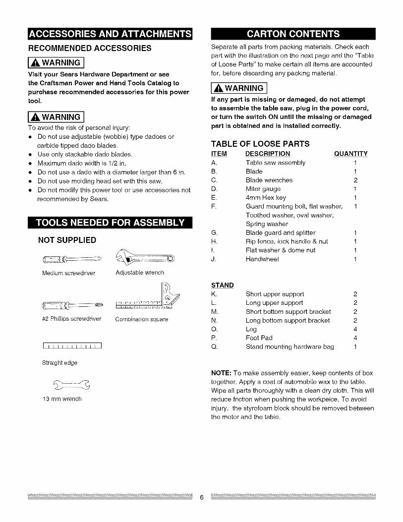
NOT SUPPLIED
Medium screwdriver
#2 Phillips screwdriver
Adjustable wrench
Combination square
[11111111111 ]
Straight edge
13 mm wrench
Separate all parts from packing materials. Check eachpart with the illustration on the next page and the "Tableof Loose Parts" to make certain all items are accounted
for, before discarding any packing material.
IA,WARNINGIIf any part is missing or damaged, do not attemptto assemble the table saw, plug in the power cord,or turn the switch ON until the missing or damaged
part is obtained and is installed correctly.
TABLE OF LOOSE PARTS
ITEM DESCRIPTION QUANTITY
A. Table saw assembly 1B. Blade 1
C. Blade wrenches 2
D. Miter gauge 1E. 4mm Hex key 1
F. Guard mounting bolt, flat washer, 1Toothed washer, oval washer,
Spring washerG. Blade guard and splitter 1H. Rip fence, lock handle & nut 11. Flat washer & dome nut 1J. Handwheel 1
STANDK.
L.M.N.
O.P.Q.
Short upper support 2Long upper support 2
Short bottom support bracket 2Long bottom support bracket 2Leg 4Foot Pad 4
Stand mounting hardware bag 1
NOTE: To make assembly easier, keep contents of boxtogether. Apply a coat of automobile wax to the table.Wipe all parts thoroughly with a clean dry cloth. This willreduce friction when pushing the workpeice. To avoid
injury, the styrofoam block should be removed betweenthe motor and the table.

UNPACKING YOUR TABLE SAW
(
C DE F G
H 1 j Q
o
K
o
"1 "
N O
P

MitergaugeBladeguard Tableinsert Ripfence
Bevelanglepointer& scale
Overloadresetswitch
ON/OFFswitchwithsafetykey
Bladebevellockknob
&tiltinghanwheel
Frontstandmountingholes
Stand
BladeAnti-kickbackpawls
Splitter
Rearmountingholes
Splitterbracket
ANTI-KICKBACKPAWLS- Prevents the workpiecefrom being kicked upward or back toward the front of thetable saw by the spinning blade.
ARBOR - The shaft on which the blade or dado ismounted.
located on either side of the blade. It helps makeaccurate straight or angle crosscuts.
OVERLOAD RESET SWITCH - Resets the
thermocouple and provides a way to restart the sawmotor if it overloads or overheats.
BEVEL CUT - An angle cut made through the face ofthe workpiece.
BLADE BEVEL SCALE - Measures the angle the bladeis tilted when set for a bevel cut.
PUSH STICK - Accessory that is used to push theworkpiece through the cut to avoid placing your handsclose to the blade.
RESIN - A sticky sap that has hardened.
BLADE ELEVATION/TILTING HANDWHEEL - Raisesand lowers the blade. Tilts the blade to any anglebetween 0° and 45° for bevel cuts.
BLADE GUARD - Clear plastic cover that is positionedover the blade while cutting.
COMPOUND CUT - A simultaneous bevel and mitercut.
CROSSCUT - A cut made across the width of theworkpiece.
DADO - Special cutting blades that are used to cutgrooves in a workpiece.
DUST PORT - Hole in back of saw base for attachmentof vacuum hose.
FREEHAND - Performing a cut without using a ripfence, miter gauge, hold down or other proper device toprevent the workpiece from twisting during the cuttingoperation.
GUM - A sticky sap from wood products.
HEEL - Misalignment of the blade.
JAM NUT - Nut used to lock another nut in place on athreaded rod or bolt.
KERF - The amount of material removed by the bladecut.
MITER CUT - An angle cut made across the width ofthe workpiece.
MITER GAUGE - A guide used for crosscuttingoperations that slides in the table top channels (grooves)
REVOLUTIONS PER MINUTE (RPM) - The number ofturns completed by a spinning object in one minute.
RIP FENCE - A guide used for rip cutting that clamps tothe table top. It allows the workpiece to cut straight.
RIPPING - Cutting with the grain of solid wood or alongthe length of the workpiece.
SAW BLADE PATH - The area of the workpiece ortable top directly in line with the travel of the blade, orthe part of the workpiece that will be cut.
SET - The distance between two saw blade tips, bentoutward in opposite directions to each other. The fartherapart the tips are, the greater the set.
SPLITTER - Keeps the workpiece split apart after beingcut to prevent binding on the blade and workpiece.
TABLE INSERT - Insert that is removed from the tableto install/remove blades. It is also removed for dadocutting. When dado cutting, a dado insert plate must beused.
THROUGH-SAWING - Making a cut completelythrough the length or width of a workpiece.
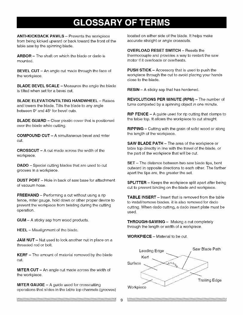
WORKPIECE - Material to be cut.
Leading Edge
Kerf
Surface
Saw Blade Path
Workpiece
Trailing Edge

ASSEMBLE STAND (FIG. A)
1. Unpack all parts and group by type and size. Referto the parts list for correct quantities.
2. Attach one long upper support (P) to top of leg (S)
using one bolt (1) and nut (2).NOTE: Do not tighten bolts until stand is properlyaligned (see step #8 before tightening).
3. Attach other end of long upper support to top of
another leg using one bolt and nut.4. Attach one long bottom support (R) to center of each
leg using bolt (1) and nut (2). This completes thefront frame section.
5. Assemble rear frame section in exactly the samemanner.
6. Join front and rear frame assemblies using two shortupper supports (O) and two short bottom supports(Q), bolts and nuts.
7. Insert foot pad (T) into bottom of leg. Repeat for
each leg.8. Place stand on level surface and adjust so all legs
are contacting the floor and are at similar angles to
the floor, and detents in stand leg align with supportbrackets, then tighten all bolts.NOTE: Stand should not rock after all bolts are
tightened.
Fig. A
ASSEMBLE TABLE SAW TO STAND (FIG. A-l)1. Place protective cardboard or old blanket on floor to
protect the saw table surface.2. Place the saw up side down on the protective
material (see Fig. A-1 ).3. Position the stand up side down on the saw base.
NOTE: Make sure front of stand and front of saw are
facing the same direction.4. Line up the four holes in saw base and stand.
5. Fasten saw to stand using four bolts (3), washers(4) and nuts (5).
NOTE: Place washer on each bolt before insertinginto saw base and through the support. Nut must beimmediately against the bracket (see Fig. A).
6. Carefully set the saw in its upright position on aclean level surface.
7. Tighten all four nuts.NOTE: DO NOT OVER TIGHTEN NUTS HOLDINGSAW TO STAND. THIS MAY DAMAGE THE SAWBASE,
WARNING IIF THE STAND WILL NOT BE USED, DO NOTOPERATE THE TABLE SAW ON THE FLOOR. THISIS A VERY DANGEROUS POSITION.
Fig. A-1
3
o
s
10
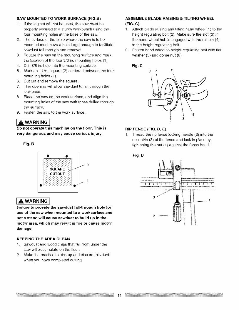
SAWMOUNTED TO WORK SURFACE (FIG.B)
1. If the leg set will not be used, the saw must beproperly secured to a sturdy workbench using the
four mounting holes at the base of the saw.2. The surface of the table where the saw is to be
mounted must have a hole large enough to facilitatesawdust fall-through and removal.
3. Square the saw on the mounting surface and mark
the location of the four 3/8 in. mounting holes (1).4. Drill 3/8 in. hole into the mounting surface.
5. Mark an 11 in. square (2) centered between the fourmounting holes (1).
6. Cut out and remove the square.7. This opening will allow sawdust to fall through the
saw base.
8. Place the saw on the work surface, and align themounting holes of the saw with those drilled throughthe surface.
9. Fasten the saw to the work surface.
I_ WARNING IDo not operate this machine on the floor. This is
very dangerous and may cause serious injury.
Fig. B
CUTOUT
I_k WARNING IFailure to provide the sawdust fall-through hole foruse of the saw when mounted to a worksurface and
not a stand will cause sawdust to build up in the
motor area, which may result in fire or cause motordamage.
KEEPING THE AREA CLEAN
1. Sawdust and wood chips that fall from under thesaw will accumulate on the floor.
2. Make it a practice to pick up and discard this dustwhen you have completed cutting.
ASSEMBLE BLADE RAISING & TILTING WHEEL
(FIG. C)1. Attach blade raising and tilting hand wheel (1) to the
height regulating bolt (2). Make sure the slot (3) inthe hand wheel hub is engaged with the roll pin (4)in the height regulating bolt.
2. Fasten hand wheel to height regulating bolt with flatwasher (5) and dome nut (6).
Fig. C6 5 2
43
1
RIP FENCE (FIG. D, E)1. Thread the rip fence locking handle (2) into the
eccentric (3) of the fence and lock in place bytightening the nut (1) against the fence head.
Fig. D
3 •
1

2. Liftupwardon ripfencehandle(2)sotherearholdingclamp(4)is fullyextended.
3. Placetheripfenceonthesawtable(5),engagingtherearfenceclampfirstthenloweringthefrontendontothetable.
4. Pushdownonthefencehandle(2)to lock.
Fig. E
5
//
Fig. H
@
1
J/
o__ 2
2. Raise the blade arbor (4) (Fig. 1)to the maximum
height by turning the blade raising handwheelcounterclockwise.
3. Place the open-end wrench (8) jaws on the flats of
the saw arbor to keep the arbor from turning (Fig. J)and place the box-end wrench (9) on the arbor nut(5), and turn counterclockwise.
4. Remove the arbor nut (5) and outer flange (6) (Fig. 1).
INSTALLING AND CHANGING THE BLADE
(FIG. H, I, J)
DANGER I• To avoid injury from an accidental start, make
sure the switch is in the OFF position and the
plug is not connected to the power sourceoutlet.
• To avoid serious injury, the rear of the tableinsert must be level with the table. If the rear of
the insert is not level with the table, adjust thescrew (3) in or out until the rear of the insert islevel to or slightly above the table. To raise the
insert, turn the screw counterclockwise, to lowerthe insert, turn the screw clockwise. NOTE: Arubber adjusting spacer is provided under rear
of insert for this purpose.
Remove the table insert (1) by removing the twoscrews (2, 3). Be careful not to lose the rubberspacer that is on the back screw (3) beneath the
table insert (Fig. H).

5.
6.
Install the saw blade onto the arbor with the blade
teeth pointing toward the front of the saw.Install the flange (6) against the blade and threadthe arbor nut (5) as far as possible by hand. Ensurethat the blade is flush against the inner side of the
blade flange.
I,dk WARNING ITo avoid possible injury and damage to theworkpiece, be sure to install the blade with the teeth
pointing toward the front of table in the direction ofthe rotation arrow on the blade guard.
Fig. I4
5
7. To tighten the arbor nut (5) place the open-end
wrench (8) on the flats of the saw arbor to keep thearbor from turning (Fig. J).
8. Place the box-end wrench (9) on the arbor nut (5),and turn clockwise (to the rear of the saw table).
9. Replace the blade insert in the table recess, insertthe screws through the front and rear holes andtighten remembering the rubber washer under the
rear of the insert and leveling the rear of the insertto the table.
Fig. J
8
9
BLADE GUARD ASSEMBLY (FIG. K, L, M)
1. Set the blade to maximum height and the tilt to zerodegrees on the bevel scale with the hand wheels.Lock the blade bevel lock knob.
2. Place the spring washer (2), flat washer (3), externaltooth lock washer (4) onto the blade guard mountingbolt (1) (Fig. K).
3. Insert bolt and washer assembly through splitter
bracket (5).5
\11
4.
5.
Fig. K
Blade Guard-"
Splitter
Place the oval washer (6) on the pivot rod (7) (Fig. L).Install the blade guard splitter & bracket assemblyinto the rear of the saw table. Thread the bolt (1)
into the internally threaded pivot rod until snug.NOTE: The blade guard and splitter is removed fromthe illustration for clarity.
Fig. L
7 6
6. Lift blade guard arm (8) up and using a straightedge, align the blade guard splitter (9) with the sawblade (10).
7. Shift the splitter bracket assembly to right or left until
parallel alignment to the blade is achieved.8. When the splitter is properly aligned with the saw
blade, tighten the bolt securely.
NOTE: The splitter bracket must always be correctlyaligned so the cut workpiece will pass on either sidewithout binding or twisting.
I_ WARNING ITo avoid injury from a thrown workpiece, blade
parts, or blade contact, never operate saw withoutthe proper insert in place. Use the original installedinsert for all through sawing operations except dado
cuts. A special dado insert plate must be installedwhen using a dado blade.
13
WARNING ISee Fig. K flat washer (11) must be under
knob (12). NOTE: Be sure to tighten knob very tightand periodically check tightness.
IA DANGER IImproper splitter alignment can cause "kickback"and serious injury.

Fig, M
Kickback pawl 10
Straight edge
MITER GAUGE ADJUSTMENT (FIG. N)
1. To check miter gauge squareness, loosen lockhandle (1) to allow miter body (3) to rotate freely.Position the miter head so the pointer (2) points to
90 ° on the scale. Tighten lock handle to hold miterhead in position. Use a square to verify the 90°angle between the miter body and the slide bar.
2. If adjustment is needed, square the miter head to 90°,loosen the pointer locking screw and adjust pointerto 90° on the protractor scale then tighten thelocking screw.
3. To change angles on miter gauge, loosen lockhandle (1) and rotate miter body to desired angle asindicated by the pointer (2). Secure in position by
tightening the lock handle.
Fig. N
RIP FENCE ADJUSTMENT (FIG. O)1. The fence (1) is moved by lifting up on the locking
handle (2) and sliding the fence to the desired
location. Pushing down on the handle locks thefence in position.
2. Position the fence on the table and along one edge
of the miter gauge grooves.3. Lock the fence handle. The fence should be parallel
with the miter gauge groove.
4. If adjustment is needed to make the fence parallel to
the groove, proceed with the following adjustments:• Loosen the two bolts (3) and lift up on the
handle (2).• Hold the fence bracket (4) firmly against the
front of the saw table. Move the far end of the
fence until it is parallel with the miter gauge
groove.• Push the handle to lock, then tighten both bolts.
5. If fence is loose when the handle is in the locked
(downward) position, proceed with the followingadjustment:
• Lift the handle (2) upward and turn the adjustingscrew (5) clockwise until the bottom of the rear
clamp is 1/16 in. away from the rear of the table.
NOTE: Over-tightening the adjusting screw will cause
the fence to come out of alignment.
WARNINGIFailure to properly align fence can cause "kickback"
and serious injury.
NOTE: The rip fence and blade are aligned parallel tothe miter gauge groove of the table.
Fig. O
1
8 6 7
3
u5
RIP FENCE INDICATOR ADJUSTMENT (FIG, O)1. The rip fence indicator (6) points to the rip scale
(8). The scale references the distance between thefence and the blade.
2. Measure the actual distance with a rule. If thereis a difference between the measurement and the
indicator, adjust the indicator (6).3. Loosen the screw (7) and slide the indicator to the
correct measurement on the scale. Tighten thescrew and re-measure.
14
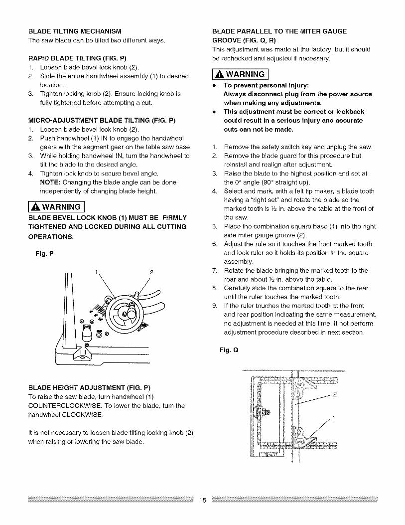
BLADE TILTING MECHANISM
The saw blade can be tilted two different ways.
RAPID BLADE TILTING (FIG. P)1. Loosen blade bevel lock knob (2).
2. Slide the entire handwheel assembly (1) to desiredlocation.
3. Tighten locking knob (2). Ensure locking knob is
fully tightened before attempting a cut.
MICRO-ADJUSTMENT BLADE TILTING (FIG. P)
1. Loosen blade bevel lock knob (2).2. Push handwheel (1) IN to engage the handwheel
gears with the segment gear on the table saw base.
3. While holding handwheel IN, turn the handwheel totilt the blade to the desired angle.
4. Tighten lock knob to secure bevel angle.
NOTE: Changing the blade angle can be doneindependently of changing blade height.
I,dk WARNING I
BLADE BEVEL LOCK KNOB (1) MUST BE FIRMLYTIGHTENED AND LOCKED DURING ALL CUTTING
OPERATIONS.
Fig. P
1 2
/
BLADE HEIGHT ADJUSTMENT (FIG. P)To raise the saw blade, turn handwheel (1)COUNTERCLOCKWISE. To lower the blade, turn thehandwheel CLOCKWISE.
It is not necessary to loosen blade tilting locking knob (2)
when raising or lowering the saw blade.
BLADE PARALLEL TO THE MITER GAUGE
GROOVE (FIG. Q, R)This adjustment was made at the factory, but it should
be rechecked and adjusted if necessary.
I,A WARNING I• To prevent personal injury:
Always disconnect plug from the power sourcewhen making any adjustments.
• This adjustment must be correct or kickbackcould result in a serious injury and accuratecuts can not be made.
1. Remove the safety switch key and unplug the saw.
2. Remove the blade guard for this procedure butreinstall and realign after adjustment.
3. Raise the blade to the highest position and set at
the 0° angle (90° straight up).4. Select and mark, with a felt tip maker, a blade tooth
having a "right set" and rotate the blade so themarked tooth is Y2 in. above the table at the front ofthe saw.
5. Place the combination square base (1) into the rightside miter gauge groove (2).
6. Adjust the rule so it touches the front marked toothand lock ruler so it holds its position in the squareassembly.
7. Rotate the blade bringing the marked tooth to therear and about Y2in. above the table.
8. Carefully slide the combination square to the rearuntil the ruler touches the marked tooth.
9. If the ruler touches the marked tooth at the front
and rear position indicating the same measurement,
no adjustment is needed at this time. If not performadjustment procedure described in next section.
Fig. Q
2
15

ADDITIONAL BLADE ADJUSTMENTS (FIG. R)TOOLS REQUIRED
• 10 mm open end or 10 mm combination wrench
• 4 mm hex key• Framing square• Medium size flat blade screw driver
ADJUSTMENT PROCEDURE
1. Turn saw switch OFF and remove plug from thepower source.
2. Remove blade guard and splitter assembly, mitergauge and rip fence.
3. Using the 10 mm hex wrench, slightly loosen thetwo middle blade alignment rod strap bolts (1) andtwo-rear blade alignment rod strap bolts (2) located
on the underside of the saw table. (Fig. R)
Fig. R
2 I
_m2
ii
1 H
bolts (3) while holding the rod firmly in place.
NOTE: The blade alignment rod will only moveslightly to the right.
7. Tighten both middle blade alignment rod strapbolts (1). NOTE: Re-check to make sure all six bolts
are properly tightened and that the distance from thefront and rear of the blade to the miter gauge grooveare within 1/64th of an inch from one another.
8. Re-install blade guard and splitter assembly andadjust the alignment with the blade as outlinedearlier in the operator's manual.
0° BEVEL STOP (FIG. S)
1. Raise the blade to maximum height by rotating thehandwheel counterclockwise.
2. Loosen bevel angle lock knob.3. Tilt the blade to 0° bevel.
4. Using a square (1), verify blade is 90° to the tabletop.
5. If blade is not 90 ° to the table, back off the
adjustment screw (2).6. Loosen bevel lock knob and square blade 90° to the
table.
7. Once blade is at 90° to the table top, lock bevelangle locking knob.
8. Carefully tighten adjusting screw (2) until it touches
the bevel stop. DO NOT OVER TIGHTEN.9. Recheck to ensure blade is still aligned at 90°.
Fig, S
4. While standing at the rear of the saw, use a mediumsize flat blade screwdriver and gently pry the rear
of the blade alignment rod to the LEFT or RIGHT.Using the framing square, simultaneously measurethe distance at the front and rear of the blade to an
edge of a miter slot. When the distances are within
1/64 in. or closer, tighten both rear blade alignmentrod strap bolts (2) while holding the rod firmly inplace. NOTE: The blade alignment rod will only
move slightly.5. If alignment is not achieved by rear adjustment,
loosen the two front blade alignment rod strap
bolts (3).6. While standing at the front of the saw, use a
medium size flat blade screw driver and gently prythe front of the blade alignment rod to the RIGHT
or LEFT. Simultaneously measure the distance atthe front and rear of the blade to an edge of a miterslot. When the distances are with in 1/64 in. or
closer, tighten both front blade alignment rod strap
16
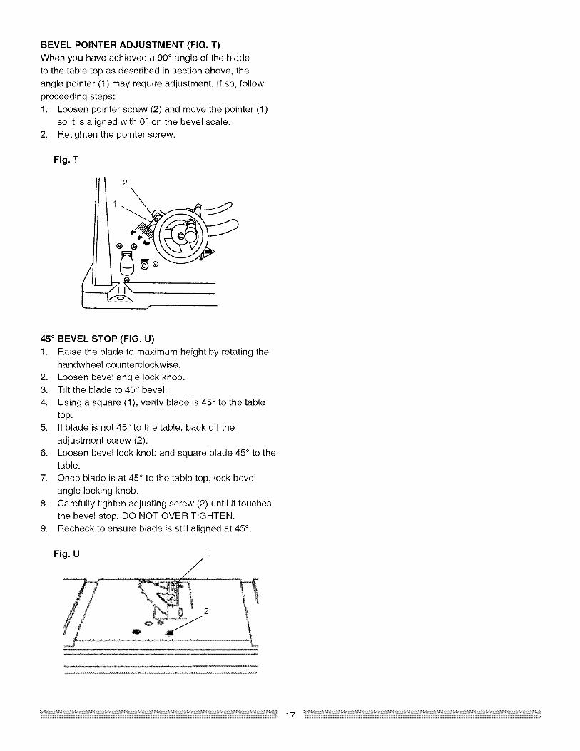
BEVEL POINTER ADJUSTMENT (FIG. T)
When you have achieved a 90° angle of the bladeto the table top as described in section above, the
angle pointer (1) may require adjustment. If so, followproceeding steps:
1. Loosen pointer screw (2) and move the pointer (1)so it is aligned with 0° on the bevel scale.
2. Retighten the pointer screw.
Fig. T
1
45 ° BEVEL STOP (FIG. U)
1. Raise the blade to maximum height by rotating thehandwheel counterclockwise.
2. Loosen bevel angle lock knob.3. Tilt the blade to 45 ° bevel.
4. Using a square (1), verify blade is 45 ° to the tabletop.
5. If blade is not 45 ° to the table, back off the
adjustment screw (2).6. Loosen bevel lock knob and square blade 45° to the
table.
7. Once blade is at 45 ° to the table top, lock bevelangle locking knob.
8. Carefully tighten adjusting screw (2) until it touches
the bevel stop. DO NOT OVER TIGHTEN.9. Recheck to ensure blade is still aligned at 45° .
Fig. U

BASIC SAW OPERATIONS
ON/OFF SWITCH (FIG. V)
The on/off switch (1) is located on the front panel of thesaw base. To turn the saw ON, move the switch to the
up position. To turn the saw OFF, move the switch tothe down position.
LOCKING SWITCH IN "OFF" POSITION (FIG. V)
When the saw is not in use, the switch should be lockedin the OFF position. To lock the switch in the OFF
position, pull out the safety key (2) from of the switch.The saw will not start with the key removed. However,
if the key is removed while the switch is in the ONposition, it can be turned off ONCE. The saw will not
restart until the key has been reinserted into the switchand the switch is turned on.
OVERLOAD PROTECTION (FIG. V)
This saw is equipped with an overload reset switch. Ifthe motor shuts off or fails to start due to overloading or
low voltage, turn the switch to OFF position and let themotor cool down and remove all cutting materials from
the saw. After the motor has cooled down, push thereset button (3) to reset the overload device. The sawshould now start when the switch is returned to the ON
position.
To avoid injury, the ON/OFF switch should be in the
OFF position and the plug removed from the powersource while the motor cool down takes place. This
will prevent accidental starting when the reset buttonis pushed. Overheating may be caused by misaligned
parts, a dull blade, or an undersized extention cord.Inspect the saw for proper setup before using it again.
Fig. V
across the width or across the grain of the workpiece.Neither ripping nor crosscutting may be done safely
freehand. Ripping requires the use of the rip fence, andcrosscutting requires the miter gauge. Never use a rip
fence and miter gauge at the same time.
la,WARNINGIBefore using the saw each and every time, check
the following:1. Blade is tight on the arbor.
2. Bevel angle lock knob is tight.3. If ripping, fence lock handle is tight and fence is
parallel to the blade.4. Blade guard is in place and working properly.
5. Safety glasses are being worn.
The failure to adhere to these common safety rules, and
those printed within this manual, can greatly increase
the likelihood of injury.
RIPPING(FIGW, X)
I_ WARNINGI* Do not allow familiarity or frequent use of
your table saw to cause careless mistakes.Remember that even a careless fraction of a
second is enough to cause a severe injury.. Keep both hands away from the blade and path
of the blade.
. The workpiece must have a straight edge againstthe fence and must not be warped, twisted, orbowed.
DANGER[Never attempt to pull the workpiece backwardsduring a cutting operation. This will cause kickbackand serious injury to the user can occur.
_ RESETo
CUTTING OPERATIONS
There are two basic types of cuts: ripping andcrosscutting. Ripping is cutting along the length and with
the grain of the workpiece. Crosscutting is cutting either
18
1. Remove the miter gauge. Secure the rip fence tothe table at the desired rip measurement.
2. Raise the blade so it is about 1/8 in. higher than thetop of the workpiece.
3. Place the workpiece flat on the table and against the
fence. Keep the workpiece about 1 in. away fromthe blade.
4. Turn the saw ON and wait for the blade to come up
to speed.5. Slowly feed the workpiece into the blade by pushing
forward only on the workpiece section (1) that willpass between the blade and the fence. (Fig. W)

I_ WARNING I
AVOID KICKBACK by pushing forward that section
of the workpiece that will pass between the bladeand the fence. Use a push stick at all times.
Fig, W
RIPPING SMALL PIECES
la,WARNINGIAvoid injury from the blade contact. Never makethrough-saw cuts narrower than 3/4 in. wide.
1.
2.
It is unsafe to rip small pieces. Instead, rip a larger
piece to obtain the size of the desired piece.When a small width is to be ripped, your handcannot be safely put between the blade and the ripfence, therefore, use one or more push sticks to
pass the workpiece completely through and past theblade.
6. Keep your thumbs off the table top. When your handreaches the front edge of the table (2), finish the cut
with a push stick (3) (Fig. X). You can make a pushstick using the pattern on page 28.
7. The push stick (3) should always be used during all
ripping operations.8. Continue pushing the workpiece with the push stick
(3) until it passes the blade guard and clears therear of the table.
DANGER[Never attempt to pull the workpiece backwardsduring a cutting operation. This will cause kickbackand serious injury to the user can occur. Whenthe blade completely stops raise the anti-kickback
pawls on each side of the splitter and slide theworkpiece out.
1
Fig. X3
BEVEL RIPPING
This cut is the same as ripping except the blade bevel
angle is set to an angle other than "0".
I_ WARNING ICut only with the workpiece and the fence on the
right side of the blade.
IA DANGER INever attempt to pull the workpiece backwards
during a cutting operation. This will cause kickbackand serious injury to the user can occur.
CROSSCUTTING 90° MITER ANGLE (FIG. Y)
IA.WARNING[To prevent serious injury:
• Do not allow familiarity or frequent use ofyour table saw to cause careless mistakes.Remember that even a careless fraction of a
second is enough to cause a severe injury.• Keep both hands away from the blade and the
path of the blade.
• Never attempt to pull the workpiece backwardsduring a cutting operation. This will causekickback and serious injury to the user canoccur,
1. Remove the rip fence and place the miter gauge amiter gauge groove on the table.
2. Adjust the blade height so it is 1/8 in. higher thanthe top of the workpiece.
3. Hold the workpiece firmly against the miter gaugewith the blade path in line with the desired cut
location. Move the workpiece to one inch distancefrom the blade.
4. Start the saw and wait for the blade (1) to come up
to full speed. Never stand directly in line of the sawblade path, always stand to the side of the bladethat you are cutting on.
5. Keep the workpiece (2) against the face of the miter
gauge (3) and flat against the table. Then slowlypush the workpiece through the blade.
6. Do not try to pull the workpiece back with the blade
turning. Turn the switch OFF, and carefully slidethe workpiece out when the blade is completelystopped.
IA.WARNING[Always position the larger surface of the workpieceon the table when crosscutting and/or bevel
crosscutting to avoid unstability.
19

Fig, Y
BEVEL CROSSCUTTING (FIG. AA)0o-45 ° BLADE BEVEL & 90° MITER ANGLE
This cutting operation is the same as crosscuttingexcept the blade is at a bevel angle other than 0°.
I WARNINGAlways work to the right side of the blade duringthis type of cut. The miter gauge must be in the right
side groove because the bevel angle may cause theblade guard to interfere with the cut if used on the
left side groove.
1. Adjust the blade (1) to the desired angle, and tightenthe blade bevel lock knob.
2. Tighten miter lock handle (2) at 90° .3. Hold workpiece (3) firmly against the face of the
miter gauge throughout the cutting operation.
Fig, AA
1. Set the miter gauge (3) to the desired angle.
2. Place the miter gauge in the right side groove ofthe table.
3. Set the blade (1) bevel to the desired bevel angleand tighten the blade bevel lock knob.
4. Hold workpiece (2) firmly against the face of themiter gauge throughout the cutting operation.
Fig, BB
1 3
MITERING (FIG. CC) 0°~45 ° MITER ANGLEThis sawing operation is the same as crosscutting
except the miter gauge is locked at an angle otherthan 90 °.
1. Set the blade (1) to 0° bevel angle and tighten theblade bevel lock knob.
2. Set the miter gauge (3) at the desired miter angleand lock in position by tightening the miter gauge
locking handle.3. Hold the workpiece (2) firmly against the face of the
miter gauge throughout the cutting operation.
Fig, CC
COMPOUND MITER CROSSCUTTING (FIG. BB)0°~45 ° BLADE BEVEL & 0°~45 ° MITER ANGLE
This sawing operation is combining a miter angle with abevel angle.
I_WARNINGAlways work to the right side of the blade duringthis type of cut, The miter gauge must be in the right
side groove because the bevel angle may cause theblade guard to interfere with the cut if used on the
left side groove,
20

USING WOOD FACING ON THE RIP FENCE (FIG.
DD)When performing some special cutting operations,
You can add a wood facing (1) to either side of the ripfence (2).
1.
2.
Use a smooth straight 3/4 in. thick wood board (1)that is as long as the rip fence.
Attach the wood facing to the fence with woodscrews (3) through the holes in the fence. A woodfence should be used when ripping material such as
thin paneling to prevent the material from catchingbetween the bottom of the fence and the table.
Fig, DD
I_ WARNING IABRASIVE AND METAL CUTTING BLADES MUST
NOT BE USED WITH THIS SAW
This saw was not made to cut metals or masonrymaterials, Doing so may result in injury. It will also
void the warranty.
I,dk WARNING IALL BLADES MUST:
1. Be rated at 5000 RPM or higher.2. Have a 518 in. arbor hole.
3. Be no larger in diameter than 10 in.
Smaller diameter blades may be used. While this will
result in a reduced depth of cut, the output of the motorwill be increased.
DADO CUTS (FIG. EE)
b.
C.
1.
I,A. WARNING Ia. Only Stackable dado blades can be used on this
saw,
DO NOT use Adjustable or Wobble type dadoes.Maximum dado cut width is 1_ in.
A dado table insert must be purchased separately
for this saw to accept a dado blade. Removesaw blade and blade guard for dado cuts ONLY.Reinstall and realign blade guard for all through
sawing operations. Install a dado not exceeding 6in. in diameter and Y2in. in width
2. Install the dado table insert making sure the rear of
the insert is flush with the table. A rubber adjustingspacer is provided under the rear of the insert forthis purpose.
3. Instruction for operating the dado is packed with the
separately purchased dado set.4. The arbor (1) on this saw restricts the maximum
width of the cut to Y2 in.
5. It is not necessary to install the outside flange (2)before threading on the arbour nut (3) for maximumY2in. dado cuts. Make sure that the arbor nut (3) istight, and that at least one thread of the arbor sticks
out past the nut.6. Use only the correct number of round outside blades
and inside chippers as shown in the dado set'sinstruction manual. Blade/chippers must not exceedY2in. total in width.
7. Check saw to ensure that the dado will not strike the
housing, insert, or motor when in operation.
IA WARNING IFor your own safety, always replace the blade, blade
guard assembly, and blade insert when you arefinished with the dado operation. You must alsorealign the blade guard assembly.
Fig, EE 2
3
21

GENERAL MAINTENANCE Fig. FF
I_ WARNING IFor your own safety, turn the switch OFF andremove the switch key. Remove the plug from
the power source outlet before maintaining orlubricating your saw.
1. Clean out all sawdust that has accumulated inside
the saw cabinet and the motor.
2. Polish the saw table with an automotive wax to keepit clean and to make it easier to slide the workpiece.
3. Clean cutting blades with pitch and gum remover.4. A worn, cut, or damaged power cord should be
replaced immediately.
I_ WARNING IAll electrical or mechanical repairs should beattempted only by a trained repair technician.Contact the nearest Sears Service Center for
service. Use only identical replacement parts. Any
other parts may create a hazard.
5. Use liquid dish washing detergent and water toclean all plastic parts. NOTE: Certain cleaning
chemicals can damage plastic parts.6. Avoid use of the following cleaning chemicals or
solvents; ammonia and household detergents
containing ammonia.
BLADE RAISING AND TILTING MECHANISMAfter each five full hours of operation, the blade raisingmechanism and tilting mechanism should be checked
for looseness, binding, or other abnormalities. With thesaw disconnected from the power source, turn the saw
upside down and alternately pull upward and downwardon the motor unit. Observe any movement of the motor
mounting mechanism. Looseness or play in the bladeraising screw (1) (Fig. FF) should be adjusted as follows:
1. Using a 14 mm wrench, loosen the check-nut (2).2. Adjust nut (3) until it is finger-tight against the
bracket (4), then back off the nut (3) 1/6 turn.3. Tighten nut (2) with the wrench, while holding nut (3)
in place. Maximum allowable play of screw rod (1) is4 ram.
32
,.J ,o o
You can place a small amount of dry lubricant onbevel andgle adjustment rod also. This rod (1) must be
kept clean and free of sawdust, gum, pitch, and othercontaminants for smooth operation.
If excessive looseness is observed in any parts of the
blade raising mechanism or tilting mechanism, take thecomplete unit to a Sears Service Center.
LUBRICATIONAll motor bearings are permanently lubricated at thefactory and require no additional lubrication.
On all mechanical parts of your table saw where a pivotor threaded rod are present, lubricate using graphite or
silicone. These dry lubricants will not hold sawdust aswould oil or grease.
22

I_ WARNING I
To avoid injury from an accidental start, turn the switch OFF and always remove the plug from the powersource before making any adjustments,
• Consult your local Sears Service Center if for any reason the motor will not run.
SYMPTOM POSSIBLE CAUSES CORRECTIVE ACTION
Saw will not start. 1. Saw not plugged in.2. Fuse blown or circuit breaker tripped.3. Cord damaged.4. Debris in on/off switch
1.
2.
3.4.
1.
1.2.3.
Does not make accurate 45° 1. Positive stop not adjusted correctly. 1._nd 90° rip cuts.
2. Tilt angle pointer not set accurately. 2.
Material pinched blade when 1. 1.dpping. 2. 2.
Material binds on splitter.
Saw makes unsatisfactory_uts.
4.
5.
Material kicked back fromolade.
Rip fence not aligned with blade.Warped wood, edge against fence isnot straight.
Splitter not aligned correctly with blade.
Dull blade.Blade mounted backwards.
Gum or pitch on blade.
1.
2.
3.4.
5.6.
Incorrect blade for work being done.
Gum or pitch on blade causing erraticfeed.
Rip fence out of adjustment.Splitter not aligned with blade.Feeding stock without rip fence.
Splitter not in place.Dull blade.
The operator letting go of materialbefore it is past saw blade.
Miter angle lock knob is not tight.
Sawdust and dirt in elevation/tiltingmechanisms.
Extension cord too light or too long.Low house voltage.
Saw not mounted securely toworkbench.Bench on uneven floor.
Damaged saw blade.
Miter gauge out of adjustment.
Plug in saw.Replace fuse or reset circuit breaker.Replace power cord.Remove switch from saw and
separate in half. Clean any debrisaccumulated within.
Check blade with square and adjustpositive stop.Check blade with square and adjustto zero.
Check and align rip fence and blade.Select another piece of wood.
7. 7.
Blade does not raise or tilt 1. 1.
Freely.Blade does not come up to 1. 1. Replace with adequate size cord.speed. 2. 2. Contact your electric company.
Machine vibrates excessively. 1. 1. Tighten all mounting hardware.2. Reposition on flat level surface.
2. 3. Replace blade.3.
Does not make accurate 45° 1. 1. Adjust miter gauge._nd 90° crosscuts.
1. Check and align splitter with blade.
1. Replace blade.2. Turn the blade around.3. Remove blade and clean with
turpentine and coarse steel wool.4. Change the blade.
5. Clean table with turpentine and steelwool.
1. Align rip fence with miter gauge slot.2. Align splitter with blade.3. Install and use rip fence.
4. Install and use splitter. (with guard)5. Replace blade.6. Push material all the way past saw
blade before releasing work.
Tighten knob.
Brush or blow out loose dust and dirt.
23

10 IN. TABLE SAW PARTS LIST MODEL NO. 137.218020
I_ WARNING I
When servicing use only CRAFTSMAN replacement parts. Use of any other parts many create a HAZARDor cause product damage. Any attempt to repair or replace electrical parts on this Table Saw may create aHAZARD unless repair is done by a qualified service technician. Repair service is available at your nearestSears Service Center.
I.D. NO Description Size Qty
09JK WRENCH 1
0AVB BODY SHELL 1
0AW8 SEGMENT GEAR 1
0B1M WHEEL 1
0B21 HEIGHT REGULATING BOLT 1
0B23 SADDLE 1
0B24 SPRING 1
0B25 POINTER BRACKET 1
0B2C SWITCH BOX 1
0B3H iNSERT #23 1
0B3R WRENCH 1
0B3W RETAINING CLIP 1
0B48 WARNING LABEL 1
0B61 LiNK 1
0B6R CLAMP HANDLE 1
0B6S CLAMP HANDLE 1
0B84 WASHER D=cp18 1
0B99 SPACER 1
0B9C PLUNGER HOUSING 1
0B9G ANGLE ROD 1
0B9M STRAP 6
0B9W BRACKET 1
0B9Z COMPRESSION SPRING 1
0BA1 COMPRESSION SPRING 1
0BA4 SPACER 1
0BAC SET NUT 1
0BAE ARBOR COLLAR 1
0BAJ BLADE 1
0BPA LOCK KNOB 1
0G1U DUST SHIELD 4
0J3P HEX. WRENCH 1
0J4E FLAT WASHER cp6* 13-1 1
0J4F FLAT WASHER @8* 16-2.5 1
0J4H FLAT WASHER cp10_30-0.2 2
0J70 FLAT WASHER 1/4_3/4-7/64 1
0J72 FLAT WASHER 1/4_5/8-1/16 1
0J76 FLAT WASHER 5
0J7F FLAT WASHER 5/16"7/8-5/64 1
0J7K FLAT WASHER 3/8_29/32-5/64 1
0J7V FLAT WASHER 5/8_1 3/8-5/64 1
0J8D FLAT WASHER 3/8_3/4-5/64 2
0J8K FLATE WASHER 1/4_3/4-1/16 1
0J95 SPRING WASHER @6 1
0J9H SPRING WASHER @1/4 6
0JAA WASHER @8 1
0JAE EXTERNAL TOOTH LOCK WASHER @4 2
0JC9 SPRING PIN 1
0JE7 C-RING 1
0JXL HEX. SOC. SET SCREW M10_1.5-12 1
I.D. NO Description Size
0JYN HEX. SOC. COUNTERSUNK HD. SCREW M6_1.0-25
0KOZ HEX. HD. SCREW AND WASHER M8_1.25-16
0K16 HEX. HD. SCREW AND WASHER M8_1.25-16
0K25 HEX. BOC. HD. CAP SCREW M5_0.8-20
0K3G CR. RE. RAN HD. SCREW & WASHER M5_0.8-12
0K3R CR. RE. PAN HD. SCREW & WASHER M5_0.8-12
0K5P CR. RE. COUNT HD. SCREW M6_1.0-50
0K8C CR. RE. COUNT HD. TAPPING SCREW M4_18-10
0K91 CR. RE. TRUSS HD. TAPPING SCREW M4_16-12
0KA4 CR.RE. PAN HD. TAPPING SCREW M4_16-16
0KCX CR. RE. PAN HD PLAIN WASHER TAPPING SCREW M5_0.8-10
0KEK CR. RE. PAN HD. SCREW M6_1.0-30
0KEM CR. RE. PAN HD. SCREW M6_1.0-40
0KF7 CR. RE. PAN HD. SCREW M4_0.7-12
0K J4 CAP HD. SQ. NECK BOLT M6_1.0-35
0K J5 CAP HD. SQ. NECK BOLT M6_1.0-80
0KKW CR. RE. PAN HD. ROUND NECK SCREW M6_1.0-16
0KMR HEX. NUT M5_0.8 T=4
0KMS HEX. NUT MM1.0 T=5
0KMV HEX. NUT M10"1.5 T=8
0KMW HEX. NUT M10"1.5 T=4
0KMY HEX. NUT M8_1.25 T=6.5
0KQJ CROWN NUT M8_1.25 T=12.5
0KRQ SERRATED TOOTHED HEXAGON FLANGE NUT M6_1.0 T=6
0KRX HEXAGON NUT AND FLAT WASHER M6_1.0
0KSW STRAIN RELIEF
0KTA STRAIN RELIEF
0L65 POWER CABLE ASS'Y
0LSL CiRCUiT BREAKER SWITCH
0LWC ROCKER SWITCH
0QQ0 CLAMP-CORD
0SGC HANDLE BAR
0WPL SWITCH KEY
20WQ HEX. HD. BOLT M6_1.0-50
21BN BRACKET GROUP ASS'Y
27QV DEFLECTOR
28KD TILT POINTER #23
2919 FLAT WASHER _p10_17-2 6
29PD WARNING LABEL
29R2 WARNING LABEL
2BJM MITER GAUGE ASS'Y
2BUF RIP FENCE ASSW
2ERN BLADE GUARD ASS'Y
2EUC TABLE #53
2F2F MOTOR ASS'Y
2FDU INSTRUCTION MANUAL
2FLL LABEL
2FRJ SCALE
Qty
6
4
]
]
]
3
4
8
4

10 IN. TABLE SAW SCHEMATIC MODEL NO. 137.218020
/
\
/
\ _29PD
I OK3R 2
2FDU
2EUC
_2FRJ
OClt / OBPA
919
BIM
0821
og
KMR
0B99

10 IN. TABLE SAW PARTS LIST & SCHEMATIC MODEL NO. 137.218020
STAND
I.D. No. Description
093B FOOT PAD
OJPQ HEX. HD. BOLT
OKRR SERRATED TOOTHED HEXAGON FLANGE NUT
29RE BOTTOM SUPPORT BRACKET
29RF BOTTOM SUPPORT BRACKET
29RS UPPER SUPPORT
29RT UPPER SUPPORT
29RU BRACKET
2FD4 HARDWARE BAG ASS'Y
2A10 CAP HD. SQ.NECK BOLT
Size
M8_1.25-35
M8_1.25 T=7.5
#O6
#O6
#O6
#O6
#O6
M8_0.25-_ 2
Qty
4
4
20
2
2
2
2
4
1
16
29RE2
2A1016
29RF2
29RU4
29RT2
0KRR2o
093B4
10 IN. TABLE SAW PARTS LIST & SCHEMATIC MODEL NO. 137.218020
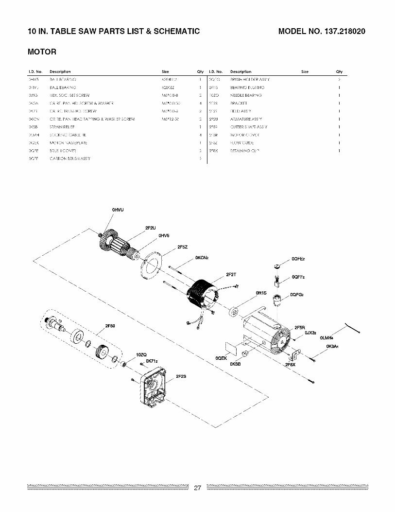
MOTOR
I.D, No. Description Size Qfy
0HV5 BALL BEARING 6204LLU 1
0HVU BALL BEARING 6200ZZ ]
OJX3 HEX SOC SET SCREW M5"08 8 2
OK3A CRRE PAN HD SCREW & WASHER M5"08 30 4
OK71 CR RE TRUSS HD SCREW M5"08 8 2
OKCN CRRE PAN HEAD TAPPING & WASHER SCREW M5"12 50 2
0KSB STRAIN RELIEF 1
0LMH LOCKING CABLE TIE 4
0QEK MOTOR NAMEPLATE 1
OQFE BRUSH COVER 2
OQFF CARBON BRUSH ASS'Y 2
I.I), No. Description
0QFG BRUSH HOLDER ASS'Y
OR1S BEARING BUSHING
10ZQ NEEDLE BEARING
2F2S BRACKET
2F2T FIELD ASS'Y
2F2U ARMATURE ASBY
2F59 CUTTER SHAFT ASBY
2F5R MOTOR COVER
2F5Z FLOW GUIDE
2FSX RETAINING CLIP
Size Qty
2
OHVU
/2FSZ
0KCN2
2F2T/
0R1S
0QF_./
_ OQFF2
2F5R
0JX32
0K3A_
/0QEK
__ 0KSB _" _2F8X
//
0LMH4
/
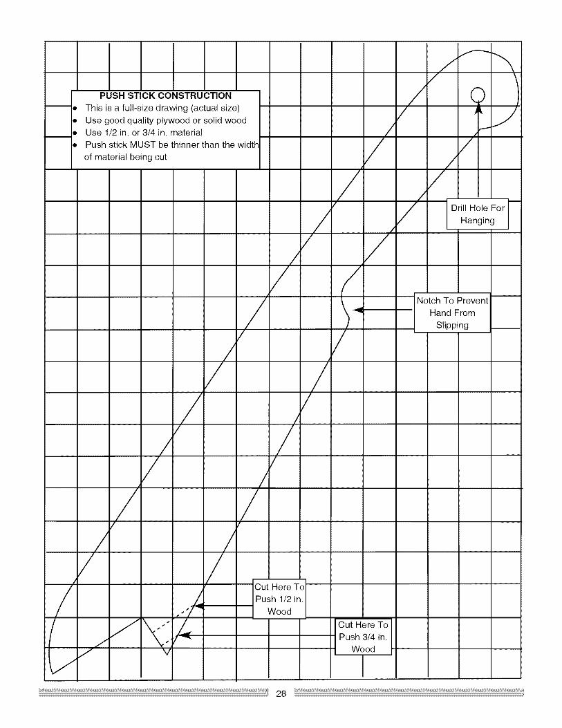
PUSH STICK CONSTRUCTION
• This is a full-size drawing (actual size)
• Use good quality plywood or solid woodUse 1/2 in. or 3/4 in. materialPush stick MUST be thinner than the width
of material being cut
Drill Hole For
Hanging
Notch To Prevent
Hand From
Slipping
//
/
Out Here ToPush 3/4 in.
Wood
Cut Here ToPush 1/2 in.
Wood

Your Home
For repair - in your home - of all major brand appliances,
lawn and garden equipment, or heating and cooling systems,
no matter who made it, no matter who sold it!
For the replacement parts, accessories and
owner's manuals that you need to do-it-yourself.
For Sears professional installation of home appliances
and items like garage door openers and water heaters.
1-800-4-MY-HOME ® (1-800-469-4663)Call anytime, day or night (U.S.A. and Canada)
www.sears.oom www.sears.oa
Our Home
For repair of carry-in items like vacuums, lawn equipment,
and electronics, call or go on-line for the location of your nearest
Sears Parts & Repair Center.
1-800-488-1222
Call anytime, day or night (U.S.A. only)
www.sears.com
To purchase a protection agreement (U.S.A.)
or maintenance agreement (Canada) on a product serviced by Sears:
1-800-827-6655 (U.S.A.) 1-800-361-6665 (Canada)
Para pedir servicio de reparaci6n
a domicilio, y para ordenar piezas:
1-888-SU-HOGAR ®(1-888-784-6427)
Au Canada pour service en fran£ais:
1-800-LE-FOYER M°
(1-800-533-6937)www.sears.ca
TM M® Registered Trademark / Trademark / s Service Mark of Sears Brands, LLC
TM M® Marca Registrada / Mama de Fglbrica / s Marca de Servicio de Bears Brands, LLC
MDMeMarque de commerce / Marque ddposee de Bears Brands, LI_C © Sears Brands, LLC