operator s manual xl4100 upper xl4200 - …mygradall.com/pdf/upper_ops_manuals/2460-4139_a... ·...
TRANSCRIPT

July 2002Starting S/N
Remote Control Units - 0418249Crawler Units - 0425250
Also Covers 0419242, 0413249, 0415249 & 0412249
OPERATOR'S MANUAL
GRADALL406 Mill Avenue S.W.
New Philadelphia, OH, 44663, USATelephone: (330) 339-2211
Fax: (330) 339-3579
XL4100 UPPERXL4200
24604139
Form #29618 Original Issue 8/96

Safe operation depends upon reliable equipment and proper operatingprocedures. Performing the checks and services described in this manualwill help to keep your Gradall R Excavator in reliable condition and use of therecommended operating procedures can help you avoid accidents.Because some procedures may be new to even the experienced operatorwe recommend that this manual be read, understood and followed by allwho operate the unit.
Strict attention to, and compliance with, instructions provided in this manual,the XL4100 6x4 & 6x6 Carrier Operation & Lubrication Manual, as well asthe EMI & Gradall Hydraulic Excavator Safety Manuals and all instructionaldecals and plates affixed to the machine, will help you avoid personal injuryand damage to the equipment. The information provided is not intended tocover all situations; it would be impossible to anticipate and evaluate allpossible applications and methods of operation for this unit.
Any procedure not specifically recommended by The Gradall Companymust be thoroughly evaluated from the standpoint of safety before it isplaced In practice. If you aren’t sure, contact your Gradall ExcavatorDistributor before operating.
Do not modify this machine without writtenpermission from The Gradall Company. Use only
genuine Gradall replacement parts.
The Gradall Company retains a proprietaryrights to the information contained in thismanual.
The Company also reserves the right tochange specifications without notice.
Gradall is a registered trademark forhydraulic excavators, hydraulic materialhandlers and attachments manufactured byThe Gradall Company.
The Gradall Company406 Mill Avenue, S.W., New Philadelphia, Ohio 44663
Form No. 29618 8/96 1K B
IMPORTANT SAFETY NOTICE
OTHER NOTICES

This manual provides important information to materialfamiliarize you with required operator maintenance andwith safe operating procedures for the GradallHydraulic Excavator.
Because two operators are sometimes assigned to theunit, operator information for the upperstructure and forthe undercarriage is provided in separate manuals.
The upperstructure includes a separate operator’s stationfor control of excavator functions and is equipped witha separate engine to power the upperstructure.
Related Manuals & DecalsSeparate publications are furnished with the excavator toprovide information concerning safety, replacementparts, maintenance procedures, theory of operation andvendor components. A kit containing all decals for yourmachine is available from your Gradall Distributor. Hecan also furnish additional manuals for your machine.
Operator QualificationsThis excavator has been designed for operatorsweighing from 104 to 220 pounds (47 to 100 kg) andfrom 59 to 73 inches (150 to 185 cm) tall. Potentialoperators beyond these limits should be observed whileoperating and driving the unit in a safe area to determinetheir ability for safe, efficient operation.
The operator must hold a valid, applicable driver ’slicense which requires acceptable age, vision, hearing,manual dexterity and response. He must also be inacceptable physical and mental condition (notundergoing medical treatment or using drugs or alcoholwhich would violate traffic laws.)
Before driving the unit on the highway or operating theexcavator at a worksite, the driver/operator mustfamiliarize himself with the machine by practicing in asafe, open area not hazardous to people or property.
INTRODUCTION
General The upperstructure operator must read, understand andcomply with instructions contained in the followingmaterial furnished with the excavator.
l This Operation & Lubrication Manuall Gradall Hydraulic Excavator Safety Manuall EMI Hydraulic Excavator Safety Manuall All Instructional decals and platesl Any optional equipment instructions furnished
If operator will also drive carrier:
XL4100 & XL4200 6x4 & 6x6 Carrier Operation & Lubrication Manual
Orientation
When used to indicate direction or location, the termsfront, rear, left and right relate to the orientation of aperson sitting in the upperstructure operator’s seat.
In relation to the carrier, front, rear right and left aredetermined by the orientation of a person in the driversseat.
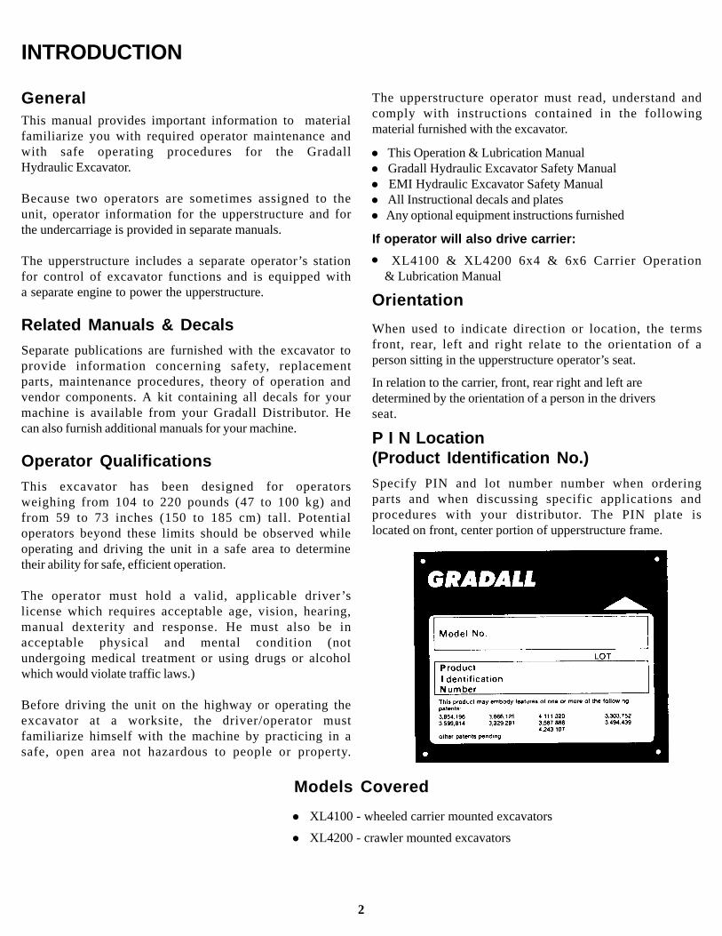
P I N Location(Product Identification No.)Specify PIN and lot number number when orderingparts and when discussing specific applications andprocedures with your distributor. The PIN plate islocated on front, center portion of upperstructure frame.
Models Covered
l XL4100 - wheeled carrier mounted excavators
l XL4200 - crawler mounted excavators
2
l
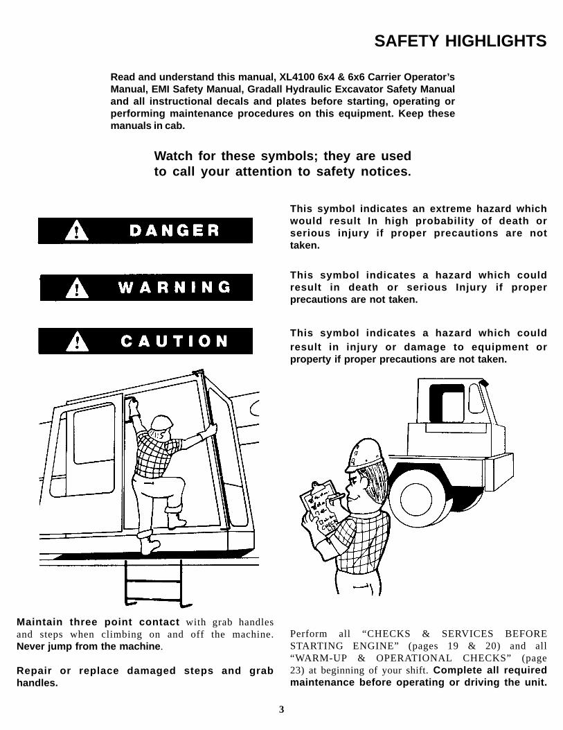
Maintain three point contact with grab handlesand steps when climbing on and off the machine.Never jump from the machine .
Repair or replace damaged steps and grabhandles.
SAFETY HIGHLIGHTS
Read and understand this manual, XL4100 6x4 & 6x6 Carrier Operator’sManual, EMI Safety Manual, Gradall Hydraulic Excavator Safety Manualand all instructional decals and plates before starting, operating orperforming maintenance procedures on this equipment. Keep thesemanuals in cab.
Watch for these symbols; they are usedto call your attention to safety notices .
This symbol indicates an extreme hazard whichwould result In high probability of death orserious injury if proper precautions are nottaken.
This symbol indicates a hazard which couldresult in death or serious Injury if properprecautions are not taken.
This symbol indicates a hazard which couldresult in injury or damage to equipment orproperty if proper precautions are not taken.
Perform all “CHECKS & SERVICES BEFORESTARTING ENGINE” (pages 19 & 20) and all“WARM-UP & OPERATIONAL CHECKS” (page23) at beginning of your shift. Complete all requiredmaintenance before operating or driving the unit.
3
SAFETY HIGHLIGHTS
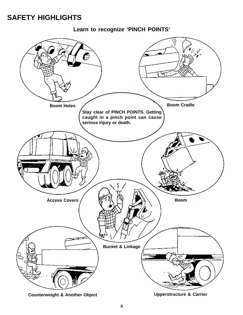
Learn to recognize ‘PINCH POINTS’
Upperstructure & Carrier
Stay clear of PINCH POINTS. Gettingcaught in a pinch point can causeserious injury or death.
Boom Cradle
4
Boom
Bucket & Linkage
Boom Holes
Access Covers
Counterweight & Another Object
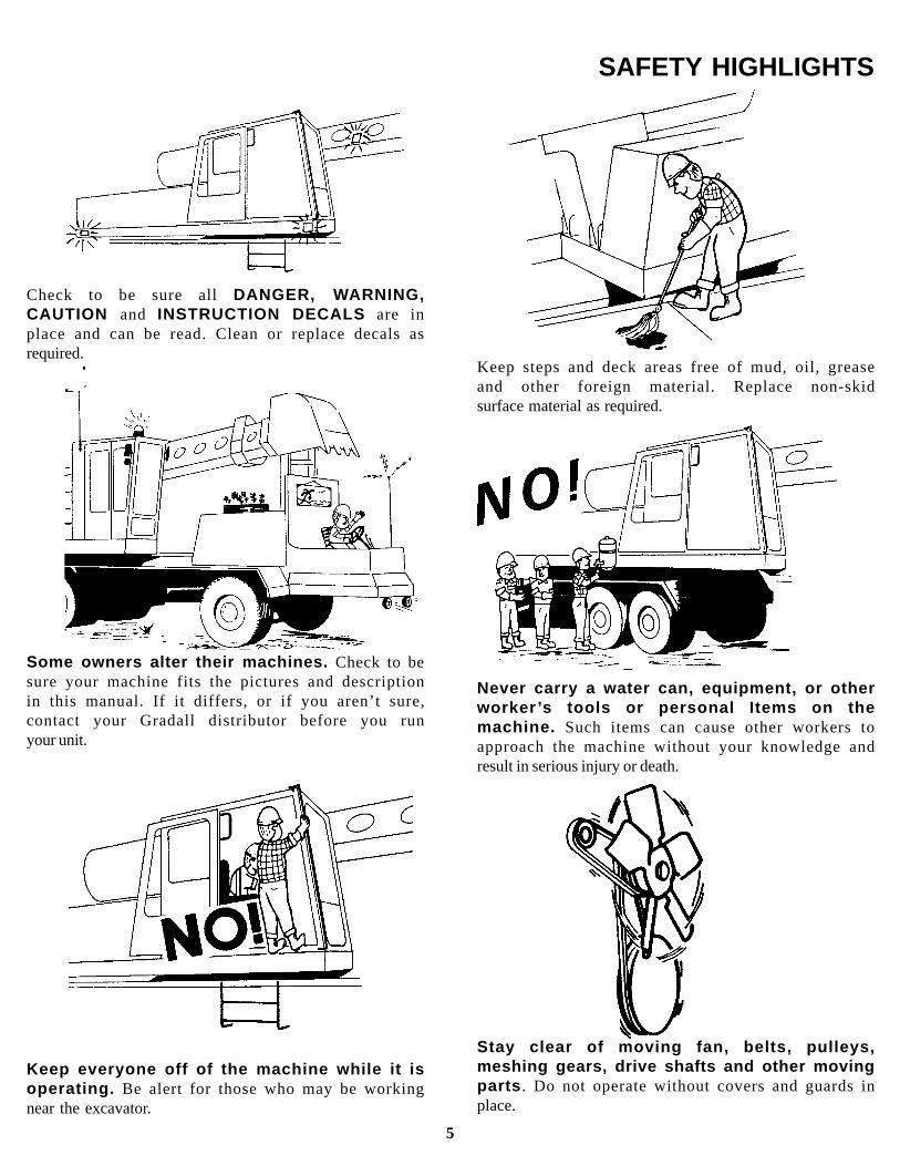
Check to be sure all DANGER, WARNING,CAUTION and INSTRUCTION DECALS are inplace and can be read. Clean or replace decals asrequired.
SAFETY HIGHLIGHTS
Some owners alter their machines. Check to besure your machine fits the pictures and descriptionin this manual. If it differs, or if you aren’t sure,contact your Gradall distributor before you runyour unit.
Keep everyone off of the machine while it isoperating. Be alert for those who may be workingnear the excavator.
Keep steps and deck areas free of mud, oil, greaseand other foreign material. Replace non-skidsurface material as required.
5
Never carry a water can, equipment, or otherworker ’s tools or personal Items on themachine. Such items can cause other workers toapproach the machine without your knowledge andresult in serious injury or death.
Stay clear of moving fan, belts, pulleys,meshing gears, drive shafts and other movingparts . Do not operate without covers and guards inplace.

Be particularly careful if this is not the machineyou usually operate. Read the manuals listed onpage 2 and then operate the unit in a safe, openarea to become familiar with the controls.
SAFETY HIGHLIGHTS
Signal persons positioned to observe andsignal operator for safe travel and guide traffic.
Boom fully retracted, horizontal and centeredover front or rear in direction of travel
Bucket positioned for maximum visibility
No load attached to any part of machine
Learn and follow your employer ’s safety rules.
Transmission in proper range
Tires properly inflated
Door secured in open or closed position
Be sure area is clear of bystander
Sound horn before moving
REPOSITION UNIT FOR EXCAVATOR OPERATION ONLY UNDER FOLLOWING CONDITIONS:
6
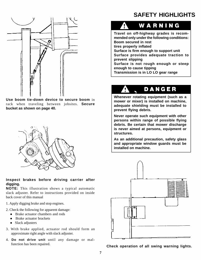
Use boom tie-down device to secure boom inrack when traveling between jobsites. Securebucket as shown on page 40.
SAFETY HIGHLIGHTS
Travel on off-highway grades is recom-mended only under the following conditions:Boom secured in resttires properly inflatedSurface is firm enough to support unitSurface provides adequate traction toprevent slippingSurface is not rough enough or steepenough to cause tippingTransmission is in LO LO gear range
Whenever rotating equipment (such as amower or mixer) is installed on machine,adequate shielding must be installed toprevent flying debris.
Never operate such equipment with otherpersons within range of possible flyingdebris. Be certain that mower dischargeis never aimed at persons, equipment orstructures.
As an additional precaution, safety glassand appropriate window guards must beinstalled on machine.
Check operation of all swing warning lights.
7
Inspect brakes before driving carrier afterdigging.NOTE: This illustration shows a typical automaticslack adjuster. Refer to instructions provided on insideback cover of this manual
1. Apply digging brake and stop engines.
2. Check the following for apparent damage:l Brake actuator chambers and rodsl Brake actuator bracketsl Slack adjusters
3. With brake applied, actuator rod should form anapproximate right angle with slack adjuster.
4. Do not drive unit until any damage or mal-function has been repaired.
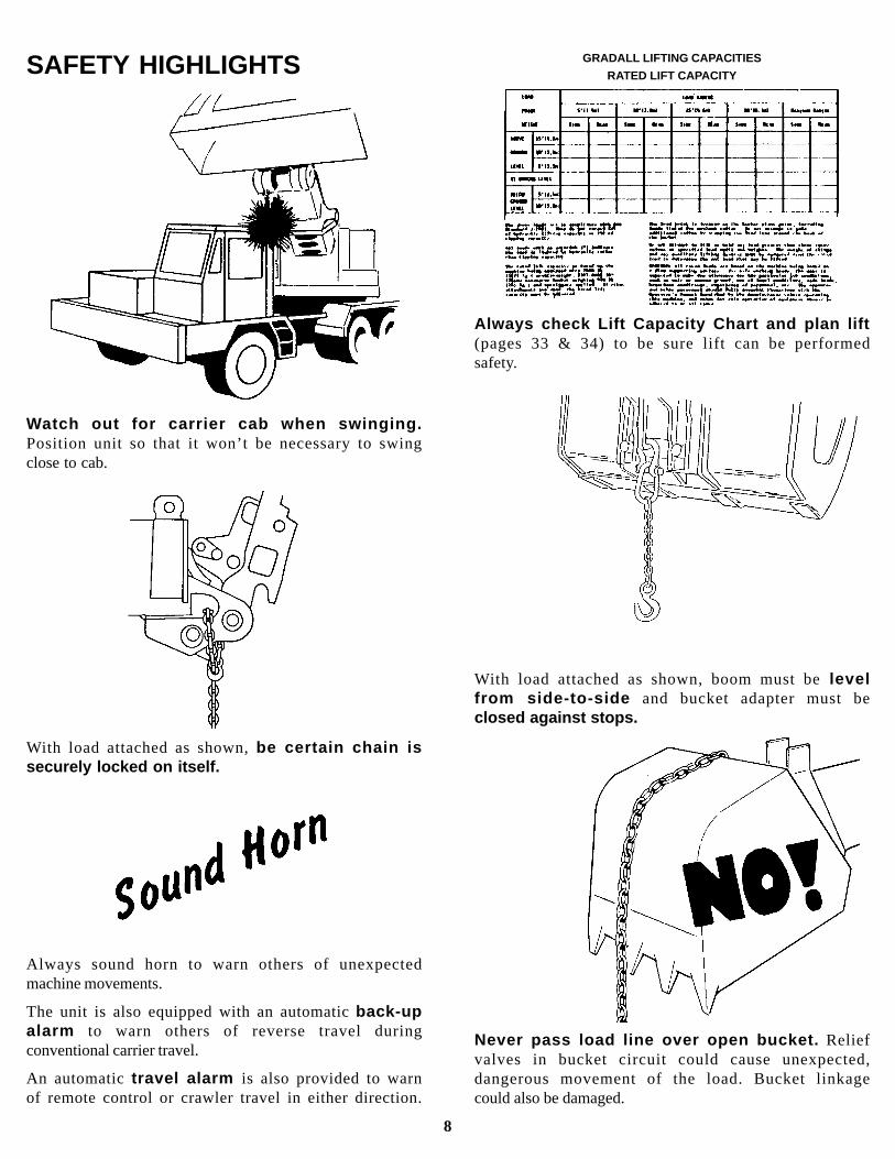
Watch out for carrier cab when swinging.Position unit so that it won’t be necessary to swingclose to cab.
SAFETY HIGHLIGHTS
With load attached as shown, be certain chain issecurely locked on itself.
GRADALL LIFTING CAPACITIES
RATED LIFT CAPACITY
Always sound horn to warn others of unexpectedmachine movements.
The unit is also equipped with an automatic back-upalarm to warn others of reverse travel duringconventional carrier travel.
An automatic travel alarm is also provided to warnof remote control or crawler travel in either direction.
8
Always check Lift Capacity Chart and plan lift(pages 33 & 34) to be sure lift can be performedsafety.
Never pass load line over open bucket. Reliefvalves in bucket circuit could cause unexpected,dangerous movement of the load. Bucket linkagecould also be damaged.
With load attached as shown, boom must be levelfrom side-to-side and bucket adapter must beclosed against stops.

Always be sure bucket is resting firmly in boomrest or on ground and that engine is stoppedbefore performing lubrication or maintenanceprocedures inside boom.
Do not operate with bystander s or otherworkers near machine.
SAFETY HIGHLIGHTS
Avoid injury! Always relieve pressure trap-ped in circuits before disconnecting, re-moving or installing hydraulic components.
Pressure can be maintained in hydraulic circuitslong after the engine has been shut down. Thispressure can cause oil (or items such as pipe plugs)to “shoot out” at high speed if pressure is notreleased correctly.
Refer to service manual for procedure torelieve hydraulic pressure trapped incircuits.
9
Be sure windows and doors are securely latched inopen or closed position when operating. Replacedefective latches and weak access cover supportstruts immediately.
Always stop engine and apply emergency brakebefore leaving upperstructure cab . However,emergency brake must be released before conven-tional carrier operation.

Located on left cab wall (crawler units only)Part No. 8091-3025 (5200 units)Part No. 8061-3012 (4200 units)
Decals Inside Cab
Located on left cab wall(crawler units only)Part No. 8091-3017
Located on left cab wallPart No. 8091-3019
(standard)
Located on left cab wall (remote units only)Part No. 8090-3001 (5100 units)Part No. 8060-3005 (4100 units)
Located on left cab wall(remote units only)Part No. 8090-3027
Located on left cab wallPart No. 8091-3038
(for aux. hyd.)
Located on left cab wall(crawler units only)Part No. 8091-3040)
(for aux. hyd.)
Located on left cab wall(remote units only)Part No. 8091-3039
(for aux. hyd.)
Located on left cab wallPart No. 8091-3041(for SAE controls)
10
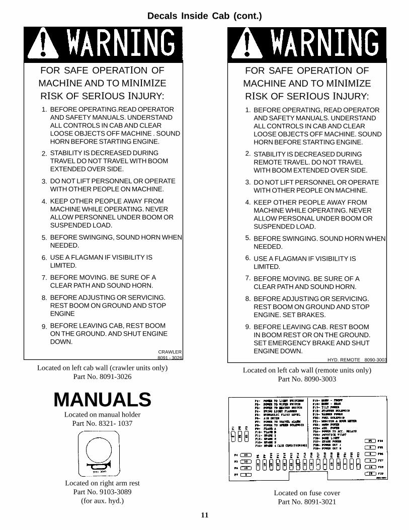
BEFORE OPERATING.READ OPERATORAND SAFETY MANUALS. UNDERSTANDALL CONTROLS IN CAB AND CLEARLOOSE OBJECTS OFF MACHINE . SOUNDHORN BEFORE STARTING ENGINE.
STABILITY IS DECREASED DURINGTRAVEL DO NOT TRAVEL WITH BOOMEXTENDED OVER SIDE.
DO NOT LIFT PERSONNEL OR OPERATEWITH OTHER PEOPLE ON MACHINE.
KEEP OTHER PEOPLE AWAY FROMMACHINE WHILE OPERATING. NEVERALLOW PERSONNEL UNDER BOOM ORSUSPENDED LOAD.
BEFORE SWINGING, SOUND HORN WHENNEEDED.
USE A FLAGMAN IF VISIBILITY ISLIMITED.
BEFORE MOVING. BE SURE OF ACLEAR PATH AND SOUND HORN.
BEFORE ADJUSTING OR SERVICING.REST BOOM ON GROUND AND STOPENGINE
BEFORE LEAVING CAB, REST BOOMON THE GROUND. AND SHUT ENGINEDOWN.
FOR SAFE OPERATION OFMACHINE AND TO MINIMIZERISK OF SERIOUS INJURY:
Decals Inside Cab (cont.)
FOR SAFE OPERATION OFMACHINE AND TO MINIMIZERISK OF SERIOUS INJURY:
CRAWLER8091 - 3026
Located on left cab wall (crawler units only)Part No. 8091-3026
MANUALSLocated on manual holder
Part No. 8321- 1037
Located on right arm restPart No. 9103-3089
(for aux. hyd.)
1.
2.
3.
4.
5.
6.
7.
8.
9.
11
Located on fuse coverPart No. 8091-3021
BEFORE OPERATING, READ OPERATORAND SAFETY MANUALS. UNDERSTANDALL CONTROLS IN CAB AND CLEARLOOSE OBJECTS OFF MACHINE. SOUNDHORN BEFORE STARTING ENGINE.
STABILITY IS DECREASED DURINGREMOTE TRAVEL. DO NOT TRAVELWITH BOOM EXTENDED OVER SIDE.
DO NOT LIFT PERSONNEL OR OPERATEWITH OTHER PEOPLE ON MACHINE.
KEEP OTHER PEOPLE AWAY FROMMACHINE WHILE OPERATING. NEVERALLOW PERSONAL UNDER BOOM ORSUSPENDED LOAD.
BEFORE SWINGING. SOUND HORN WHENNEEDED.
USE A FLAGMAN IF VISIBILITY ISLIMITED.
BEFORE MOVING. BE SURE OF ACLEAR PATH AND SOUND HORN.
BEFORE ADJUSTING OR SERVICING.REST BOOM ON GROUND AND STOPENGINE. SET BRAKES.
BEFORE LEAVING CAB. REST BOOMIN BOOM REST OR ON THE GROUND.SET EMERGENCY BRAKE AND SHUTENGINE DOWN.
1.
2.
3.
4.
5.
6.
7.
8.
9.
Located on left cab wall (remote units only)Part No. 8090-3003
HYD. REMOTE 8090-3003

TO OPERATE CARRIER FROM UPPERSTRUCTURE
Decals Outside Cab
Decals Inside Cab (cont.)
(A) FORWARD-REVERSE CONTROL PEDAL MUST BE IN NORMAL (NEUTRAL) POSITION.(B) START UPPERSTRUCTURE POWER UNIT.(C) WHEN AIR GAUGE SHOWS OPERATING PRESSURE (125 PSI), RELEASE
EMERGENCY BRAKE.(D) CONTROL AND DIRECTION OF CARRIER TRAVEL IS NOW DETERMINED BY
POSITION OF FORWARD-REVERSE CONTROL PEDAL.(E) WHEN UNDER UPPERSTRUCTURE POWER, SPEED RANGE MUST BE SELECTED
BEFORE LEAVING CARRIER,(F) DIGGING BRAKES ARE AUTOMATIC WITH FORWARD-REVERSE CONTROL PEDAL
IN NEUTRAL.
NOTE! SET EMERGENCY BRAKE WHEN LEAVING CAB.BRAKE LEVER MUST BE IN NORMAL POSITION FOR OPERATION FROM CARRIER CAB
8364-3036
Located on left window (remote units only)Part No. 8364-3035
Located on control consolePart No. 8091-3020
Located on control consolePart No. 8091-3016
Located on reservoir & inside engine coverPart No. 8090-3004
Located on reservoir & beside power fill portPart No. 9114-3288
12
HYDRAULIC SYSTEM ISPRESSURIZED
BEFORE OPENING THE HYDRAULIC SYSTEM.RELEASE AIR PRESSURE BY VENTING AIRWITH THE VALVE PROVIDED INSIDEENGINE COMPARTMENT: (LOCATED NEARHYRADRAULIC SYSTEM BREATHER.)
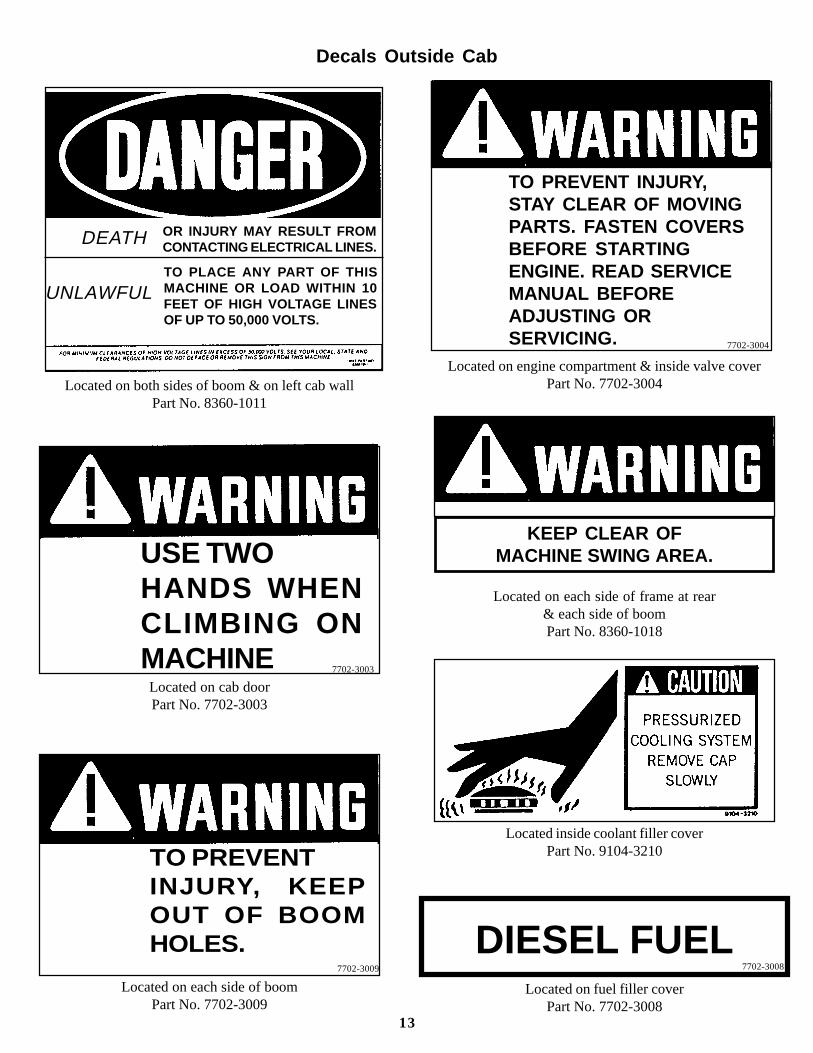
UNLAWFULTO PLACE ANY PART OF THISMACHINE OR LOAD WITHIN 10FEET OF HIGH VOLTAGE LINESOF UP TO 50,000 VOLTS.
OR INJURY MAY RESULT FROMCONTACTING ELECTRICAL LINES.
Located on each side of boomPart No. 7702-3009
Decals Outside Cab
Located on both sides of boom & on left cab wallPart No. 8360-1011
Located on cab doorPart No. 7702-3003
Located on fuel filler coverPart No. 7702-3008
13
Located on engine compartment & inside valve coverPart No. 7702-3004
Located on each side of frame at rear& each side of boomPart No. 8360-1018
DIESEL FUEL
TO PREVENTINJURY, KEEPOUT OF BOOMHOLES.
USE TWOHANDS WHENCLIMBING ONMACHINE
DEATH
TO PREVENT INJURY,STAY CLEAR OF MOVINGPARTS. FASTEN COVERSBEFORE STARTINGENGINE. READ SERVICEMANUAL BEFOREADJUSTING ORSERVICING.
Located inside coolant filler coverPart No. 9104-3210
KEEP CLEAR OFMACHINE SWING AREA.
7702-3004
7702-3003
7702-3009 7702-3008
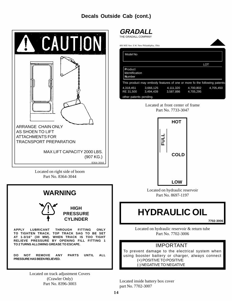
Located inside battery box coverpart No. 7702-3007
Decals Outside Cab (cont.)
Located on right side of boomPart No. 8364-3044
Located on track adjustment Covers(Crawler Only)
Part No. 8396-3003
14
WARNING
HIGHPRESSURECYLINDER
APPLY LUBRICANT THROUGH FITTING ONLYTO TIGHTEN TRACK. TOP TRACK SAG TO BE SETAT 1-3/16” (30 MM). WHEN TRACK IS TOO TIGHTRELIEVE PRESSURE BY OPENING FILL FITTING 1TO 2 TURNS ALLOWING GREASE TO ESCAPE.
DO NOT REMOVE ANY PARTS UNTIL ALLPRESSURE HAS BEEN RELIEVED.
ARRANGE CHAIN ONLYAS SHOEN TO LIFTATTACHMENTS FORTRACNSPORT PREPARATION
MAX LIFT CAPACITY 2000 LBS.(907 KG.)
8364-3044
GRADALLTHE GRADALL COMPANY
406 Mill Ave. S.W. New Philadelphia, Ohio
Model No
ProductIdentificationNumber
LOT
This product may embody features of one or more fo the following patents:
4,318,451 3,666,125 4,111,320 4,700,802 4,705,450RE 31,500 3,494,439 3,587,886 4,705,295
other patents pending.
Located at front center of framePart No. 7733-3047
FU
LL
HOT
COLD
LOW
Located on hydraulic reservoirPart No. 8697-1197
HYDRAULIC OIL
Located on hydraulic reservoir & return tubePart No. 7702-3006
IMPORTANT To prevent damage to the electrical system whenusing booster battery or charger, always connect
(+) POSITIVE TO POSITIVE(-) NEGATIVE TO NEGATIVE
7702-3006

Seat AdjustmentOPERATOR’S CAB
ARaise lever to unlock and raise armrest forentry and exit. Joysticks and pedals arede-energized.
BRaise to unlock raise or lower frontof seat. Depress lever to unlock and raise orlower rear of seat
DRaise lever to unlock and move seat to frontor rear to obtain comfortable relationship toarmrests and joysticks.
The operator’s seat includes several adjustments toincrease comport and reduce fatigue. Adjust seat tosuit your individual characteristics before startingengine.
ERaise lever to unlock and move seat/frameto front or rear to obtain comfortable rela-tionship to pedal.
CRaise lever to unlock and adjust angle ofbackrest. Headrest has no release lever butcan be adjusted from to rear as well as upand down.
Height and separation of armrests can beadjusted by loosening mounting hardware.
Perform all seat adjustment with enginestopped. Accidental actuation of controlscan cause serious accidents.
It may become necessary to revise someadjustments to find the most comfortableoperating position. Be sure to stop enginefirst.
15
HeaterThe cab is equipped with a heater located behindoperator ’s seat. Engine coolant supply to heater iscontrolled by a valve on engine block and a push/pullknob located on instrument/control console. Raiseknob fully for maximum heat or depress knob fullyfor no heat. Blower must be operated to circulateheated air.
Air Conditioner (optional)
An air conditioner can be furnished as optionalequipment. The air conditioner is controlled by atoggle switch located on instrument/control console.Air conditioner will operate only when blower switchis positioned in an operating position (High, Mediumor Low). Turn off engine coolant at engine block formaximum cooling.
Defrosting
Window defrosting can be accomplished by aimingdome-type air deflectors toward front and rearwindows while operating blower. Defrost action canbe increased by operating heater. Maximum de-frosting is accomplished by operating both heaterand air conditioner to provide warm, and air todeflectors.
BlowerThe blower is located within heater housing and iscontrolled by a rotary switch located on instrument/control console. It provides three levels of aircirculation for heating, defrosting and air condi-tioning (High, Medium or Low).Air is supplied to blower thru a vent in cab floor.Two air filter elements are provided to clean airflowing to blower. Service element as indicated inLubrication & Maintenance Diagram. Operating
conditions may require more frequent elementwashing/replacement. A noticeable reduction of airflow from deflector vents indicates a need to servicefilter elements.
VentilationIn addition to heating, defrosting and air-conditioningfunctions, the cab is equipped for varying degrees ofnatural ventilation:
Door and/or windows must be latched in fully openor closed position during upperstructure operation.
lCab door can be latched in fully opened position.
lFront window can be latched in storage position.(latch is located at center of top of window). Besure side latches are also engaged.
lWindow in right cab wall can be opened.
lOptional hatch in cab roof can be opened forventilation and/or to improve vision.
Fire ExtinguisherA fire extinguisher is located on the left cab wall.Read and understand the instructions printed on theextinguisher regarding its care and operation as wellas to the type of fires on which it may be used. Checkoften to be sure the extinguisher is fully charged.
Be sure to position boom in boom rest or onground and stop engine before opening orclosing door or front window. Accidentalactuation of controls can cause seriousaccidents.
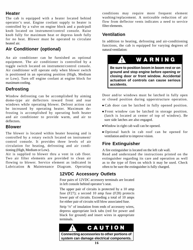
12VDC Accessory OutletsFour pairs of 12VDC accessory terminals are locatedin left console behind operator’s seat.
The upper pair of circuits is protected by a 10 ampfuse (F27); a second 10 amp fuse (F28) protectslower pair of circuits. Exceeding a total of 10 ampsfor either pair of circuits will blow associated fuse.
Strip 3/8" of insulation from ends of accessory wires,depress appropriate lock tabs (red for power andblack for ground) and insert wires in appropriateterminals.
16
Connecting accessories to other portions ofsystem can damage electrical components.
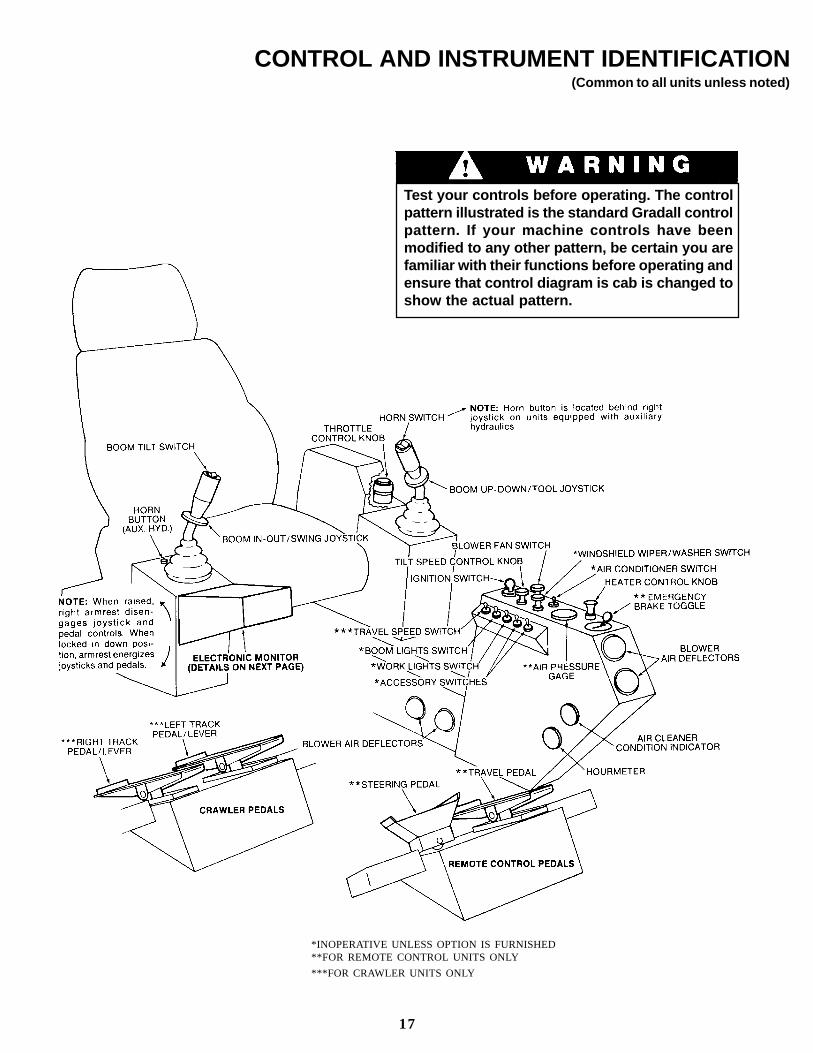
CONTROL AND INSTRUMENT IDENTIFICATION(Common to all units unless noted)
*INOPERATIVE UNLESS OPTION IS FURNISHED**FOR REMOTE CONTROL UNITS ONLY
***FOR CRAWLER UNITS ONLY
Test your controls before operating. The controlpattern illustrated is the standard Gradall controlpattern. If your machine controls have beenmodified to any other pattern, be certain you arefamiliar with their functions before operating andensure that control diagram is cab is changed toshow the actual pattern.
17
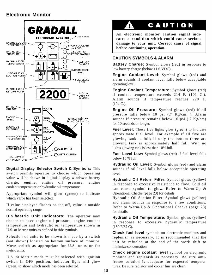
Electronic Monitor
Digital Display Selector Switch & Symbols: Thisswitch permits operator to choose which operatingvalue will be shown in digital display windows: batterycharge, engine, engine oil pressure, enginecoolant temperature or hydraulic oil temperature.
Appropriate symbol will glow (green) to indicatewhich value has been selected.
If value displayed flashes on the off, value is outsidenormal operating range.
U.S./Metric Unit Indicators: The operator maychoose to have engine oil pressure, engine coolanttemperature and hydraulic oil temperature shown inU.S. or Metric units as defined beside symbols.
Selection of units to be shown is made by a switch(not shown) located on bottom surface of monitor.Move switch as appropriate for U.S. units or formetric units.
U.S. or Metric mode must be selected with ignitionswitch in OFF position. Indicator light will glow(green) to show which mode has been selected.
18
CAUTION SYMBOLS & ALARMBattery Charge: Symbol glows (red) in response tolow battery charge (below 11.6 VDC).
Engine Coolant Level: Symbol glows (red) andalarm sounds if coolant level falls below acceptableoperating level.
Engine Coolant Temperature: Symbol glows (red)if coolant temperature exceeds 214 F. (101 C.).Alarm sounds if temperature reaches 220 F.(104 C.).
Engine Oil Pressure: Symbol glows (red) if oilpressure falls below 10 psi (.7 Kg/cm. ). Alarmsounds if pressure remains below 10 psi (.7 Kg/cm)for 10 seconds or longer.
Fuel Level: These five lights glow (green) to indicateapproximate fuel level. For example if all five areglowing tank is full; if only the bottom three areglowing tank is approximately half full. With nolights glowing tank is less than 10% full.
Fuel Level Low: Symbol glows (red) if fuel level fallsbelow 15 % full.
Hydraulic Oil Level: Symbol glows (red) and alarmsounds if oil level falls below acceptable operatinglevel.
Hydraulic Oil Return Filter: Symbol glows (yellow)in response to excessive resistance to flow. Cold oilcan cause symbol to glow. Refer to Warm-Up &Operational Checks (page 23) for details.Hydraulic Oil Suction Filter: Symbol glows (yellow)and alarm sounds in response to a few conditions.Refer to Warm-Up & Operational Checks (page 23)for details.
Hydraulic Oil Temperature: Symbol glows (yellow)in response to excessive hydraulic temperature(180 F/82 C).
Check fuel level symbols on electronic monitors andreplenish as necessary. It is recommended that theunit be refueled at the end of the work shift tominimize condensation.
Check engine coolant level symbol on electronicmonitor and replenish as necessary. Be sure anti-freeze solution is adequate for expected tempera-tures. Be sure radiator and cooler fins are clean.
An electronic monitor caution signal indi-cates a condition which could cause seriousdamage to your unit. Correct cause of signalbefore continuing operation.

Before removing filler caps or fill plugs,wipe all dirtand grease away from the ports. If dirt is allowed to
CHECKS AND SERVICESBEFORE STARTING ENGINE
(To be performed at beginning of each work shift)
Use extreme caution when checking itemsbeyond your normal reach. Use anapproved safety ladder.
Complete all required maintenance before operating unit.
enter these ports, it can shorten the life of o-rings,seals, packings and bearings.
When adding fluids or changing filter elements,refer to the lubrication section of this manual todetermine the proper type to be used.
If spark arrestors are required, be sure they are inplace and in good working order.
Service the unit in accordance with the lubricationand maintenance schedule.
Inspect unit for obvious damage, vandalismand needed maintenance. Check for signs of fuel,lubricant, coolant and hydraulic leaks. Open allaccess doors and look for loose fittings, clamps,components and attaching hardware. Replacehydraulic lines that are cracked, brittle, cut or showsigns of abrasion.
Check to be sure windows are clean.
19
Check hydraulic fluid level in reservoir with boomextended half way and bottom of bucket flat onground. Refill reservoir as necessary using properfluid.
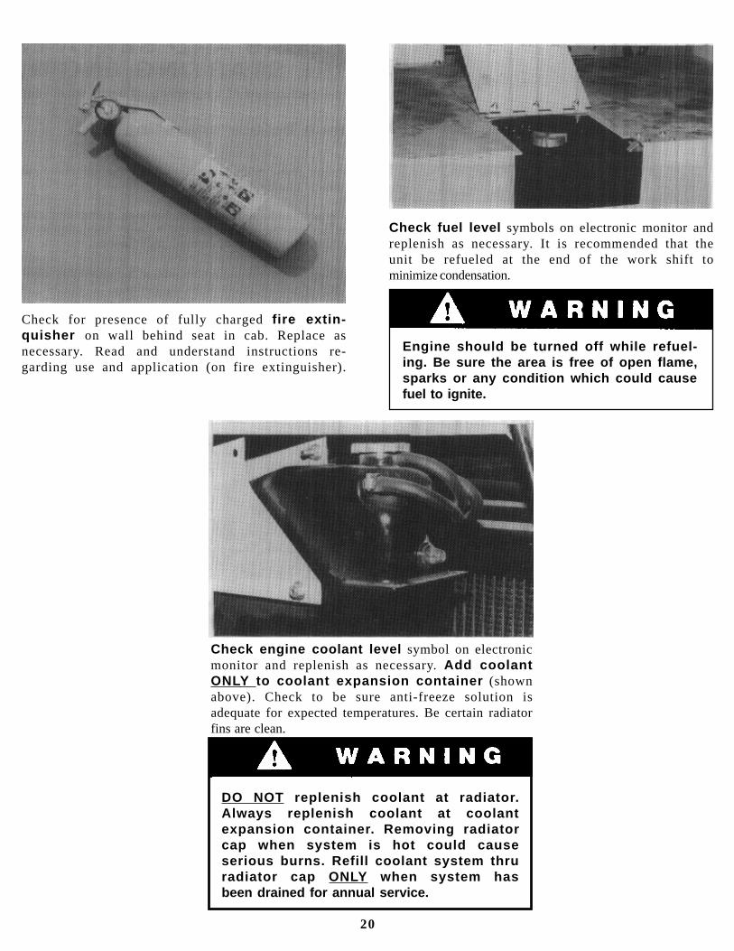
Check engine coolant level symbol on electronicmonitor and replenish as necessary. Add coolantONLY to coolant expansion container (shownabove). Check to be sure anti-freeze solution isadequate for expected temperatures. Be certain radiatorfins are clean.
Check for presence of fully charged fire extin-quisher on wall behind seat in cab. Replace asnecessary. Read and understand instructions re-garding use and application (on fire extinguisher).
Check fuel level symbols on electronic monitor andreplenish as necessary. It is recommended that theunit be refueled at the end of the work shift tominimize condensation.
DO NOT replenish coolant at radiator.Always replenish coolant at coolantexpansion container. Removing radiatorcap when system is hot could causeserious burns. Refill coolant system thruradiator cap ONLY when system hasbeen drained for annual service.
Engine should be turned off while refuel-ing. Be sure the area is free of open flame,sparks or any condition which could causefuel to ignite.
20
Starting Cummins Engine
1. Insert ignition key and turn clockwise to RUNposition while observing electronic monitor.
All monitor symbols should glow briefly as a bulbcheck. Following bulb check, symbols for batterycharge, engine oil pressure, fuel level andhydraulic oil suction filter should continue toglow and alarm should sound.
If any other symbols continue to glow, correctcause before starting engine.
2. At temperatures above 32 F. (0 C.) throttle shouldbe at low idle. At temperatures below 32°F, (0° C.)apply full throttle when cranking.
3. Sound horn as a warning before starting engine.
4. Turn ignition switch key clockwise to STARTposition to engage starter motor. Release keyimmediately when engine starts. If engine fails tostart within 30 seconds, release key and allowstarter motor to cool before trying again.
ENGINE OPERATION
NOTE: If engine is being started at beginning of work shift be sure to perform all”CHECKS ANDSERVICES BEFORE STARTING ENGINE” (pages 19 and 20).
Turning ignition switch to START position while engine flywheel is rotating can cause serious damage to engine and/or starting motor.
Cold Weather Starting Aids
Diesel engine ignition is accomplished by heatgenerated when fuel/air mixture is compressedwithin the cylinders. Because this heat may beinsufficient to start a cold engine in cold weather,the use of starting aids has become common practice.
Because of the wide variety of starting aids availableit would be impractical to attempt to provide
5. After engine starts, reduce speed to low idle andobserve engine oil pressure caution symbol onelectronic monitor. Symbol should go out toindicate proper engine oil pressure. If symbolcontinues to glow for more than fifteen seconds,stop engine and determine cause. Correct cause ofmalfunction before restarting engine.
6. Observe battery charge caution symbol. Symbolshould go out to indicate that charging system isfunctioning properly.
7. Observe hydraulic oil suction filter cautionsymbol. Symbol may go out in a few seconds toindicate hydraulic reservoir is pressurized and oilis flowing thru suction filter properly. Coldhydraulic oil may cause suction filter symbol tocontinue to glow and alarm to sound. Continue tostep 8.
8. Adjust engine speed to approximately 1500 RPMand perform warm up and operational checks innext section of manual.
specific instructions for their use in this manual.Carefully follow instructions furnished with yourstarting aid.
If you use a starting aid employing ether or asimilar substance pay particular attention tomanufacturer’s warnings.
21
Normal Engine Operation
Observe electronic monitor frequently to be sureall engine systems are functioning properly.
Engine Oil Pressure (minimum):Cummins - 10 to 30 psi (69 to 207 kPa)
Engine Operating Temperature:Cummins - 160 to 200 °F. (71 to 93 C)
Battery charge indication of alternator output:Approximately 14 volts with engine running at 2000RPM.
Always operate with engine at full throttle toprevent possibility of stalling under heavyload.
Stopping the Engine
Operate engine at idle speed for 3 to 5 minutesbefore turning it off. This allows engine coolant andlubricating oil to carry excessive heat away fromcritical engine areas. This is especially important forturbocharged engines.
Do not “gun” engine before shut down; this
Be alert for unusual noises or vibration. Whenan unusual condition is noticed, stop machine in asafe position and shut off engine. Determine causeand correct problem before continuing.
Avoid prolonged idling. Idling causes enginetemperature to drop and this permits formation ofheavy carbon deposits and dilution of lubricating oilby incompletely burned fuel. If the engine is notbeing used, turn it off.
practice causes raw fuel to remove oil film fromcylinder walls and dilute lubricant in crankcase.
CUMMINS ENGINE: To stop the Cummins engine,allow engine to idle for 3 to 5 minutes. Turn ignitionswitch key to “OFF”. Remove key if leavingequipment.
Always keep engine covers closed whileengine is running.
22
The safety, efficiency and service life of yourexcavator will be increased by performing thefollowing operational checks while the engine andhydraulic oil are warming to operating temperature.
1. Observe air pressure gage (remote control unitsonly). System should build and maintain 125 psi(862 kPa).
2. Observe electronic monitor digi tal display forappropriate values while switching to each posi-tion. Leave switch positioned for hydraulic oiltemperature display.
NOTE: Wait approximately two minutes afterstarting engine to perform step 3. This providessufficient time for compressor to pressurize hydraulicreservoir.
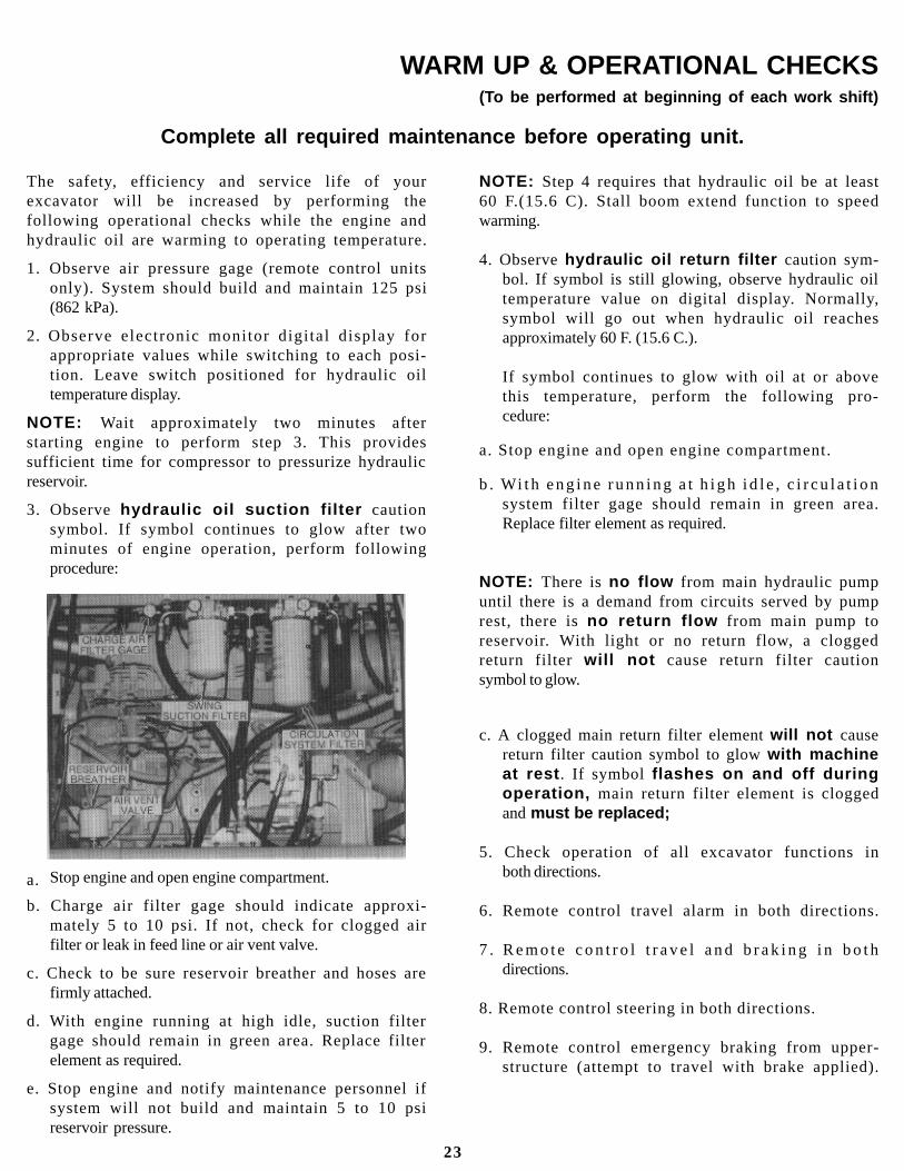
3. Observe hydraulic oil suction filter cautionsymbol. If symbol continues to glow after twominutes of engine operation, perform followingprocedure:
WARM UP & OPERATIONAL CHECKS(To be performed at beginning of each work shift)
Complete all required maintenance before operating unit.
NOTE: Step 4 requires that hydraulic oil be at least60 F.(15.6 C). Stall boom extend function to speedwarming.
4. Observe hydraulic oil return filter caution sym-bol. If symbol is still glowing, observe hydraulic oiltemperature value on digital display. Normally,symbol will go out when hydraulic oil reachesapproximately 60 F. (15.6 C.).
If symbol continues to glow with oil at or abovethis temperature, perform the following pro-cedure:
a. Stop engine and open engine compartment.
b . Wi th eng ine runn ing a t h igh i d le , c i r cu la t i onsystem filter gage should remain in green area.Replace filter element as required.
NOTE: There is no flow from main hydraulic pumpuntil there is a demand from circuits served by pumprest, there is no return flow from main pump toreservoir. With light or no return flow, a cloggedreturn filter will not cause return filter cautionsymbol to glow.
c. A clogged main return filter element will not causereturn filter caution symbol to glow with machineat rest . If symbol flashes on and off duringoperation, main return filter element is cloggedand must be replaced;
5. Check operation of all excavator functions inboth directions.
6. Remote control travel alarm in both directions.
7 . R e m o t e c o n t r o l t r a v e l a n d b r a k i n g i n b o t hdirections.
8. Remote control steering in both directions.
9. Remote control emergency braking from upper-structure (attempt to travel with brake applied).
Stop engine and open engine compartment.
b. Charge air filter gage should indicate approxi-mately 5 to 10 psi. If not, check for clogged airfilter or leak in feed line or air vent valve.
c. Check to be sure reservoir breather and hoses arefirmly attached.
d. With engine running at high idle, suction filtergage should remain in green area. Replace filterelement as required.
e. Stop engine and notify maintenance personnel ifsystem will not build and maintain 5 to 10 psireservoir pressure.
a.
23

ATTACHMENT INSTALLATION
3. Move wedge bolts forward and up until wedgecontacts bar and tighten finger-tight. Be surewedge surfaces are flush against tube and adapter.
4. Raise boom until bucket just clears ground andtighten bolts. Jog tool control to shake bucket andretighten bolts. Check often to be sure boltsremain tight.
5. Position bucket linkage as described.
24
Digging with a loose or an improperlyfitted bucket can shear adapter bolts andcause excessive wear.
1. Be sure- wedge bolts are secured (finger-tight) inposition shown and position bucket adapter abovebucket tube. Lower boom until concave section ofadapter contacts bucket tube.
2. Move adapter toward “bucket close” position untilouter end of adapter contacts bucket.
Keep boom in fully extended positionwhile Installing bucket. Stay clear untilbucket adapter has been fitted to bucket asshown in step 2.

Preparing Carrier for Remote Control Operation
REMOTE CONTROL
NOTE: Remote control is to be used for positioning unit atjob site, not for over-the-road travel.
1. With carrier on level surface, apply parking brake.
2 . S ta r t ca r r i e r eng ine and deve lop fu l l b rakesystem pressure in front and rear portions ofsystem (125 psi/862 kPa.).
3. With engine running, depress clutch and shift trans-mission to Lo Lo or LO gear range. Use Lo Lo ifoperating on a grade. First gear may be used if op-erating on hard, level surface. Move inter-axledifferential and differential lock toggles to LOCKposition for off-road conditions and for diggingover side. When sure of complete engagement, stopengine and release clutch.
2. Be sure joystick and foot pedal controls are inneutral position.
3 . S tar t uppers t ruc tu re eng ine and deve lop fu l lbrake system pressure (125 psi/862 kPa).
4. With emergency brake applied, perform followingprocedure to be sure power take-off is fullyengaged.
a. Adjust upperstructure engine speed to low idle.
b. Very gently engage travel pedal to cause a slightrotation of power take-off gear.
c. If step b caused gears to clash, power take-off wasnot engaged. Repeat step b.
If step b caused engine to reduce speed, powertake-off is fully engaged. Increase engine speedto full throttle for upperstructure operation.
5 . M o v e E M E R G E N C Y B R A K E c o n t r o l t oNORMAL position.
Serious damage can occur to engine andclutch if carrier engine is permitted to runwith digging brake engaged.
Preparing Upperstructure for Remote Control Operation
Be sure to keep feet clear of clutch pedalwhen moving DIGGING BRAKE toggle toON position (step 4).
4 . M o v e D I G G I N G B R A K E t o g g l e t o O Nposition. This applies digging brake, disengagescarrier engine clutch and engages remote drivepower take-off.
5. Release parking brake.
1 . B e s u r e c o n t r o l s i n c a r r i e r c a b h a v e b e e nproperly set for remote control operation(above).
REMOTE CONTROLS IN UPPERSTRUCTURE
25

Precautions for Remote Control Operation
Be sure of clear visibility in direction of travel;use a signalman to compensate for blind spots.
Be sure all Warm-Up and Operational Checkshave been performed.
Be sure of clear path for carrier, boom andcounterweight before starting to move. Beespecially watchful for people, overhead wiresand traffic.
Never tow load using remote control drive.
Always give audible signal before moving unit.
Never permit bucket to drag while moving unit.
Rotation of steering wheel will occur duringremote operation. KEEP CLEAR!
Be sure travel alarm functions properly.
Over the side stability is reduced during remotetravel because front axle lock cylinders auto-matically unlock when traveling.
1. Be sure controls in carrier and upperstructurecabs have been properly set for remote controloperation (see previous page).
2. Carrier speed is controlled by gear selection andamount of pedal actuation.
3. Travel pedal controls forward and reverse travel.Depressing front of pedal releases digging brakeand causes forward travel. Depressing rear ofpedal releases digging brake and causes reverse
Dr iv ing ca r r i e r f rom uppers t ruc tu re cab
travel. Gear range selection, engine speed andextent of pedal depression determine travel speed.Digging brake is applied automatically whentravel pedal is released.
4. Steering pedal controls left and right turns.Depressing right side of pedal causes right turnand depressing left side of pedal causes left turn.
5. Use EMERGENCY BRAKE to stop carrier ifautomatic digging brake fails. Move emergencybrake toggle to ON position.
Avoid confusion! Before actuating remote control steering and travel pedals,think about the direction you are facing with respect to the direction thecarrier is facing. Confusion could cause you to travel in the directionopposite that expected.
hold-down devices as necessary.
3. Allow engine to cool by running at idle speed for afew minutes. Stop engine.
4. Be sure travel and steering pedals are in neutralposition and emergency brake is released.
EMERGENCY BRAKE IN UPPER CAB MUST BE RELEASED TO MOVE CARRIER.
1. Inspect brakes before driving carrier after digging(refer to page 7).
2. With bucket opened fully, retract boom (watchbucket clearance) and position in boom rest asshown on page 7. Secure boom and bucket using
Preparing Upperstructure for Conventional Carrier Operation
4. If conditions permit, move inter-axle differentialand differential lock toggles to UNLOCK position.
5. Shift transfer case to engage or disengage frontdrive axle as appropriate for driving conditions (ifso equipped).
Prepar ing Car r ie r fo r Convent iona l Opera t ionApply parking brake.
Shift transmission to neutral.
Move DIGGING BRAKE toggle to OFFposition.
26
1.
2.
3.
Use Your Crawler Properly
Crawler undercarriages are furnished to enablethe Gradall to travel over rough terrain and reachwork sites which would not be accessible to theordinary wheeled-carrier mounted Gradall.
1. Travel in forward direction whenever possible(with track drive motors at rear). Traveling inreverse increases wear on sprockets and rollers.
2. Plan your work to equalize left and right turns.Constantly turning in one direction will causetrack components to wear unevenly.
3. Apply power to both tracks when turning. Whenpower is applied to only one track it becomesnecessary for the driving track to overcome thedrag of the other track.
4. Hard digging in one spot can cause as much trackwear as frequent moves. Do not neglect service totracks and sprockets because of infrequent moves.
5. Rough operation and operation on uneven groundcan cause unnecessary wear and damage to trackcomponents. Reasonable operation and regularmaintenance will extend track life significantly.
Crawler Controls
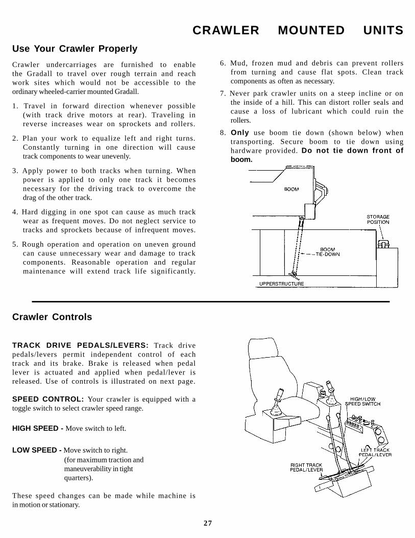
TRACK DRIVE PEDALS/LEVERS: Track drivepedals/levers permit independent control of eachtrack and its brake. Brake is released when pedallever is actuated and applied when pedal/lever isreleased. Use of controls is illustrated on next page.
SPEED CONTROL: Your crawler is equipped with atoggle switch to select crawler speed range.
HIGH SPEED - Move switch to left.
LOW SPEED - Move switch to right.(for maximum traction andmaneuverability in tightquarters).
These speed changes can be made while machine isin motion or stationary.
6. Mud, frozen mud and debris can prevent rollersfrom turning and cause flat spots. Clean trackcomponents as often as necessary.
7. Never park crawler units on a steep incline or onthe inside of a hill. This can distort roller seals andcause a loss of lubricant which could ruin therollers.
8. Only use boom tie down (shown below) whentransporting. Secure boom to tie down usinghardware provided. Do not tie down front ofboom.
CRAWLER MOUNTED UNITS
27
HOW TO OPERATE THE CRAWLER
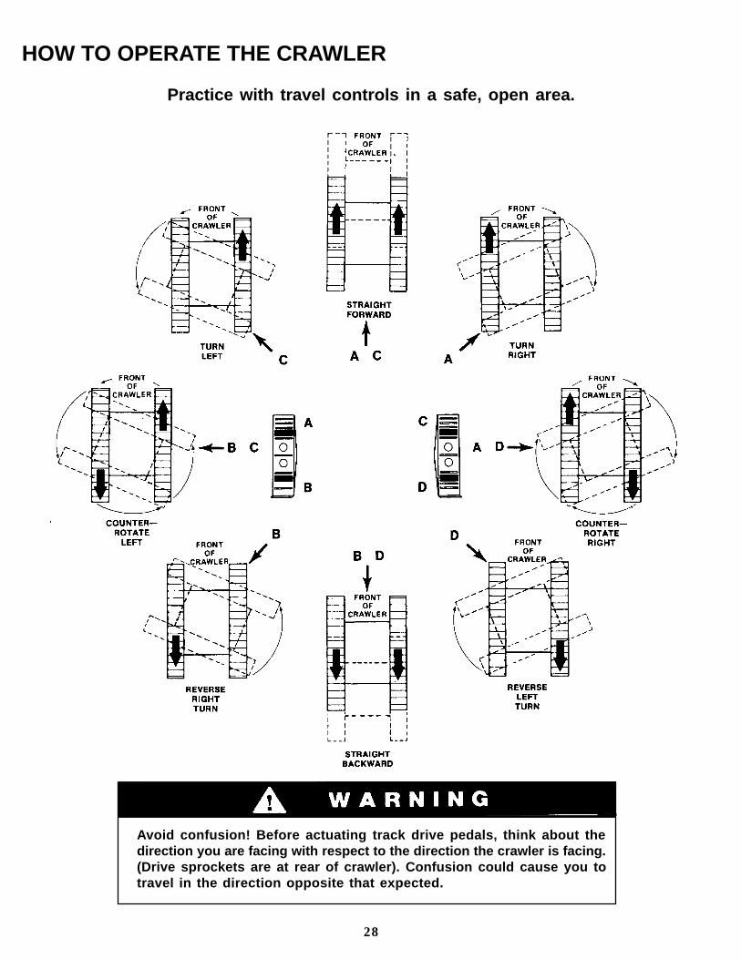
Avoid confusion! Before actuating track drive pedals, think about thedirection you are facing with respect to the direction the crawler is facing.(Drive sprockets are at rear of crawler). Confusion could cause you totravel in the direction opposite that expected.
28
Practice with travel controls in a safe, open area.

2. Stop engine and secure door and windows indesired position for ventilation. Remove boom andbucket holding devices.
A TYPICAL GRADALL DIGGING CYCLE
1. Position unit for efficient digging cycle and applydigging brake.
3. Warm up engine and hydraulic oil and then movethrottle lever to full throttle position.
Avoid accidental actuation of the controls.Always stop engine before repositioningdoor and windows.
4. Be sure right armrest is locked in down position toenergize joysticks and pedals.
Practice with controls in a safe, open area.
Always operate with engine at full throttle topresent stalling under heavy load.
*Swing torque is proportional to degree of joystick actuation.
Joysticks & pedals return to neutral position when released.
29

A TYPICAL GRADALL DIGGING CYCLE
5. Pull back on left joystick (A) to raise boom fromboom rest. Be sure to raise boom far enough toclear all obstructions.
6. Move right joystick to left (G) to swing left or toright (H) to swing right to digging site.
8. Move left joystick to left (C) to open bucket or toright (D) to close bucket for correct penetration.Teeth should angle downward slightly (about(5 ). Angle may be greater for soft digging.
30
7. While pushing right joystick forward (F) toextend boom, push left joystick forward (B) tolower boom to position for start of cut.
A TYPICAL GRADALL DIGGING CYCLE
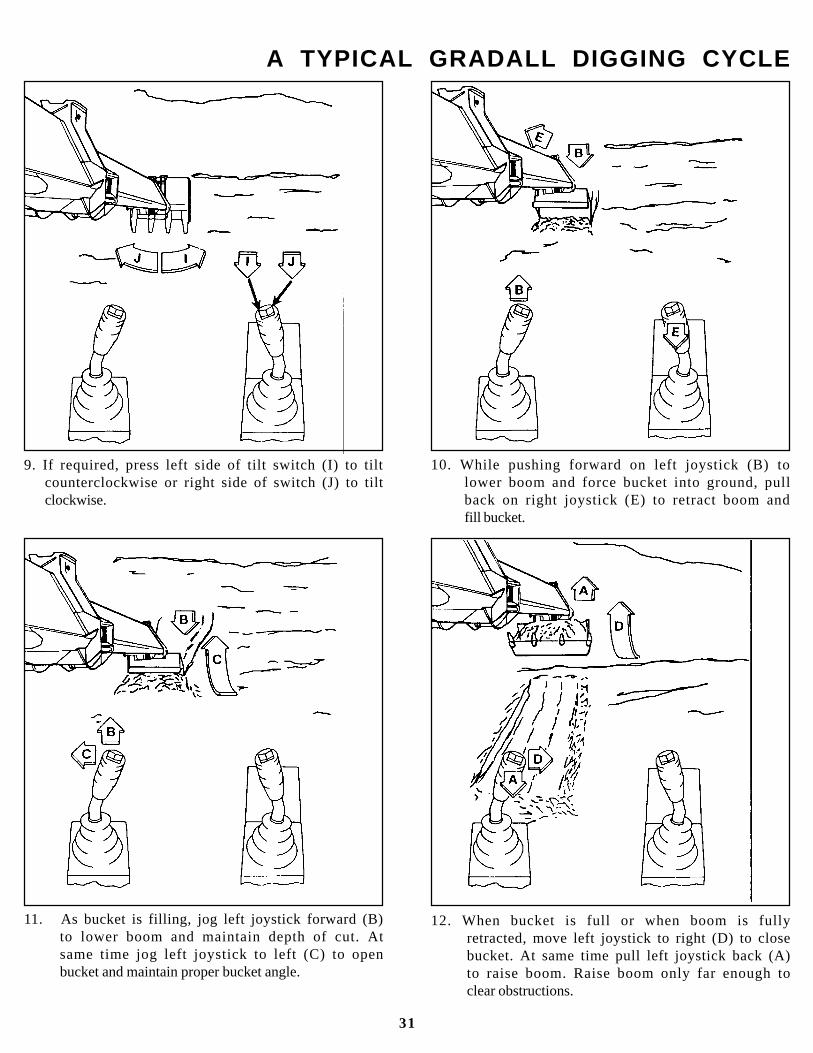
9. If required, press left side of tilt switch (I) to tiltcounterclockwise or right side of switch (J) to tiltclockwise.
12. When bucket is full or when boom is fullyretracted, move left joystick to right (D) to closebucket. At same time pull left joystick back (A)to raise boom. Raise boom only far enough toclear obstructions.
31
11. As bucket is filling, jog left joystick forward (B)to lower boom and maintain depth of cut. Atsame time jog left joystick to left (C) to openbucket and maintain proper bucket angle.
10. While pushing forward on left joystick (B) tolower boom and force bucket into ground, pullback on right joystick (E) to retract boom andfill bucket.
A TYPICAL GRADALL DIGGING CYCLE
32
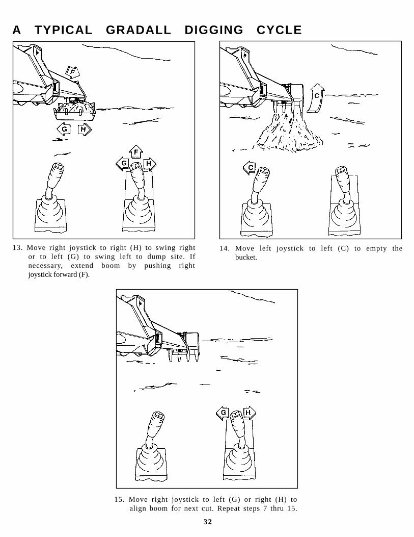
15. Move right joystick to left (G) or right (H) toalign boom for next cut. Repeat steps 7 thru 15.
13. Move right joystick to right (H) to swing rightor to left (G) to swing left to dump site. Ifnecessary, extend boom by pushing rightjoystick forward (F).
14. Move left joystick to left (C) to empty thebucket.
Precautions
Do not depend on machine tipping as a warningof overload. Some load ratings are based onhydraulic lift capacity, not stability.
Hydraulic relief valve settings must be correctwhen lifting and positioning loads.
Suspend loads only as shown. Passing load lineover open bucket can cause uncontrolled movementof load. Boom must be tilted to level position.
Always operate at full engine RPM when handlinga heavy load. This prevents stalling under load.
Keep everyone clear of machine (especially theboom and suspended load). Use guide ropes toposition load.
Do not travel with a suspended load. Excavatorsare not designed for pick and carry lifts.
Sudden swing braking can cause unexpectedmovement of the load and tip the machine.
Be sure tires are properly inflated before handlinga load.
Keep load line vertical. Side loads can causestructural damage and tip the machine.
Use appropriate lift capacity chart if unit has a boomextension attached.
Be thoroughly familiar with excavator handsignals (shown at end of manual).
Positioning Machine For A Lift
Before discussing the steps in planning a lift, let’sconsider the most favorable excavator positions formaking a lift.
The shorter the load radius, the greater the liftcapacity. Position the unit to minimize boomextension while keeping a safe distance fromobstructions and excavations.
Position the unit to minimize boom extension andswing.
Capacity over-the-rear is greater than capacityover-the-side.
Finally, position unit for maximum visibility. Ifconditions do not permit a clear view of the loadthrough entire lift, use a signal man.
Planning A Lift
Determine the weight of the load. Weight ofslings, chains and auxiliary lifting devices mustbe added as part of the load. Refer to lift capacitychart for weight adjustment required for bucket.
NOTE: Lift capacities are based on machine beingon a firm level surface and also on load being freelysuspended as shown.
Move the machine to the best probable positionfor making the lift.
LIFTING AND POSITIONING A LOAD
General
The excavator can lift and position loads safelyONLY IF YOU PLAN THE LIFT PROPERLY.
There is a great lift capacity difference between theexcavator ’s best and worst lift positions. Justbecause it can lift a load from one point does notmean it can safely move the load to any other point.
For example, the best lifting position is over the rearwith the excavator level and the boom fully retracted.Assume that you have just lifted the maximum ratedload from a truck with the unit in this position. Theonly things you can safely do with the load are raise,lower or swing it over the rear. Swinging over the sideor extending the boom will exceed the rated capacityof the unit.
The “common sense” and “feel” an experiencedoperator might apply in regard to “tipping loads”DOES NOT APPLY to loads limited by hydrauliclift capacity. Some loads shown on the chart in cabare Hydraulic Lift Capacities. Exceeding thesecapacities can cause a relief valve to open allowingthe load to fall, or in some cases, the machine to tip.
To avoid exceeding capacities, the entire lift must beplanned.
Failure to plan a lift properly can causedeath or serious injury.
33
1.
2.
3. Perform an unloaded trial run of the lift todetermine maximum load radius required andmaximum boom height and depth required tocomplete the lift.
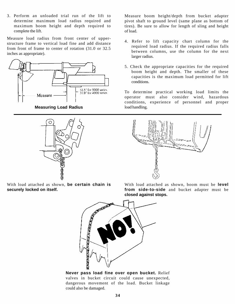
Measure load radius from front center of upper-structure frame to vertical load fine and add distancefrom front of frame to center of rotation (31.0 or 32.5inches as appropriate).
Measure boom height/depth from bucket adapterpivot shaft to ground level (same plane as bottom oftires). Be sure to allow for length of sling and heightof load.
4. Refer to lift capacity chart column for therequired load radius. If the required radius fallsbetween columns, use the column for the nextlarger radius.
5. Check the appropriate capacities for the requiredboom height and depth. The smaller of thesecapacities is the maximum load permitted for liftconditions.
To determine practical working load limits theoperator must also consider wind, hazardousconditions, experience of personnel and properload handling.
Never pass load fine over open bucket. Reliefvalves in bucket circuit could cause unexpected,dangerous movement of the load. Bucket linkagecould also be damaged.
Measuring Load Radius
With load attached as shown, be certain chain issecurely locked on itself.
With load attached as shown, boom must be levelfrom side-to-side and bucket adapter must beclosed against stops.
34
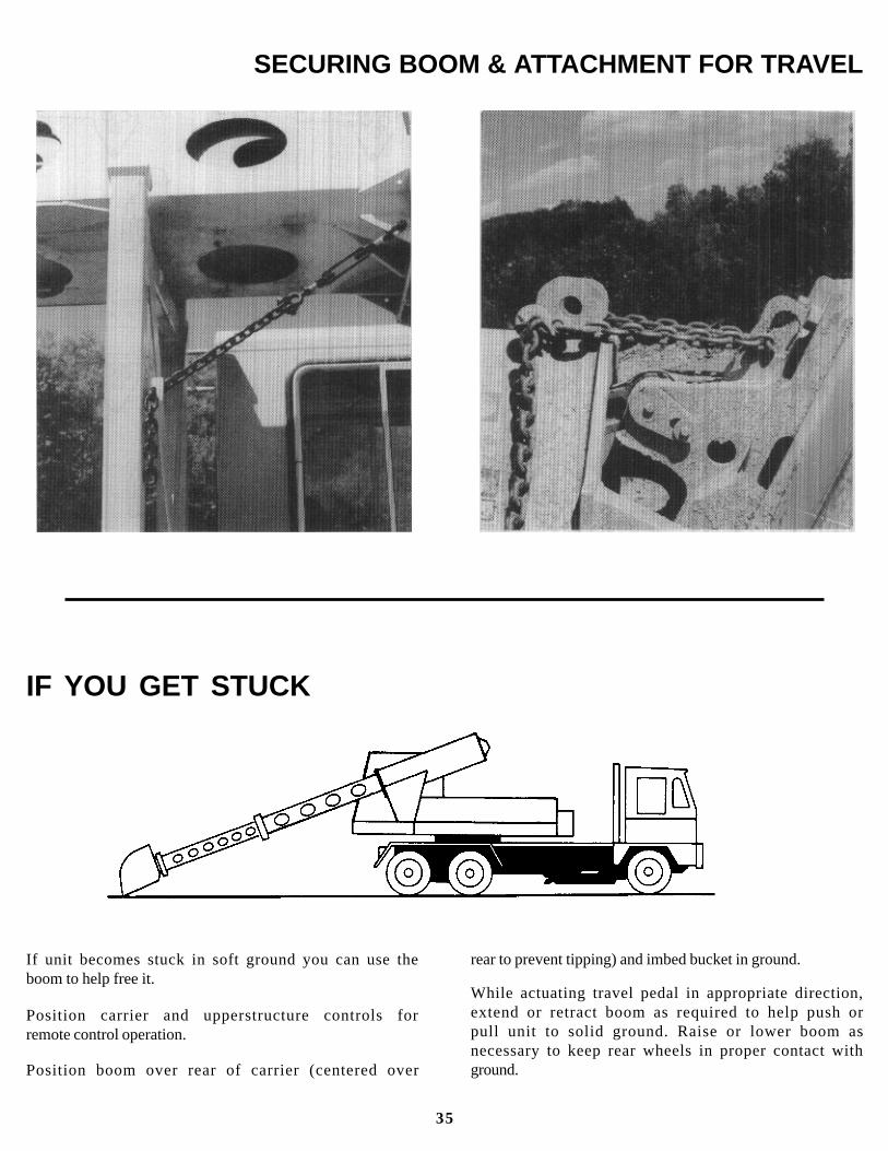
SECURING BOOM & ATTACHMENT FOR TRAVEL
IF YOU GET STUCK
If unit becomes stuck in soft ground you can use theboom to help free it.
Position carrier and upperstructure controls forremote control operation.
Position boom over rear of carrier (centered over
rear to prevent tipping) and imbed bucket in ground.
While actuating travel pedal in appropriate direction,extend or retract boom as required to help push orpull unit to solid ground. Raise or lower boom asnecessary to keep rear wheels in proper contact withground.
35

RAISE LOAD VERTICALLY - With either forearmvertical, forefinger pointing up, move hand in smallhorizontal circle.
EXCAVATOR HAND SIGNALS
Standard Signals - When excavator work conditionsrequire hand signals, they shall be provided orposted conspicuously for the use of both signalmanand operator. No excavator motions shall be madeunless signals are clearly understood by bothsignalman and operator.
Special Signals - When signals for auxiliaryequipment functions or conditions not covered arerequired, they shall be agreed upon in advance bythe operator and signalman.
Instructions - When it is desired to give instructionsto the operator other than provided by theestablished signal system, all excavator motionsshall first be stopped.
MOVE LOAD IN HORIZONTALLY - With either armextended, hand raised and open toward direction ofmovement, move hand in direction of requiredmovement.
LOWER BOOM - With either arm extended horizon-tally, fingers closed, point thumb downward.
SWING - With either arm extended horizontally,point with forefinger to direction of swing rotation.
MOVE LOAD OUT HORIZONTALLY - With eitherarm extended, hand raised and open towarddirection of movement, move hand in direction ofrequired movement.
EXTEND TELESCOPIC BOOM - With both handsclenched, point thumbs outward.
SWING - With either arm extended horizontally,point with forefinger to direction of swing rotation.
LOWER LOAD VERTICALLY - With either armextended downward, forefinger pointing down,move hand in small horizontal circle.
RAISE BOOM - With either arm extended horizon-tally, fingers closed, point thumb upward.
RETRACT TELESCOPIC BOOM - With both handsclenched, point thumbs inward.
OPEN BUCKET - Hold one hand open and station-ary. Rotate other hand in small vertical circle withforefinger pointing horizontally at open hand.
36
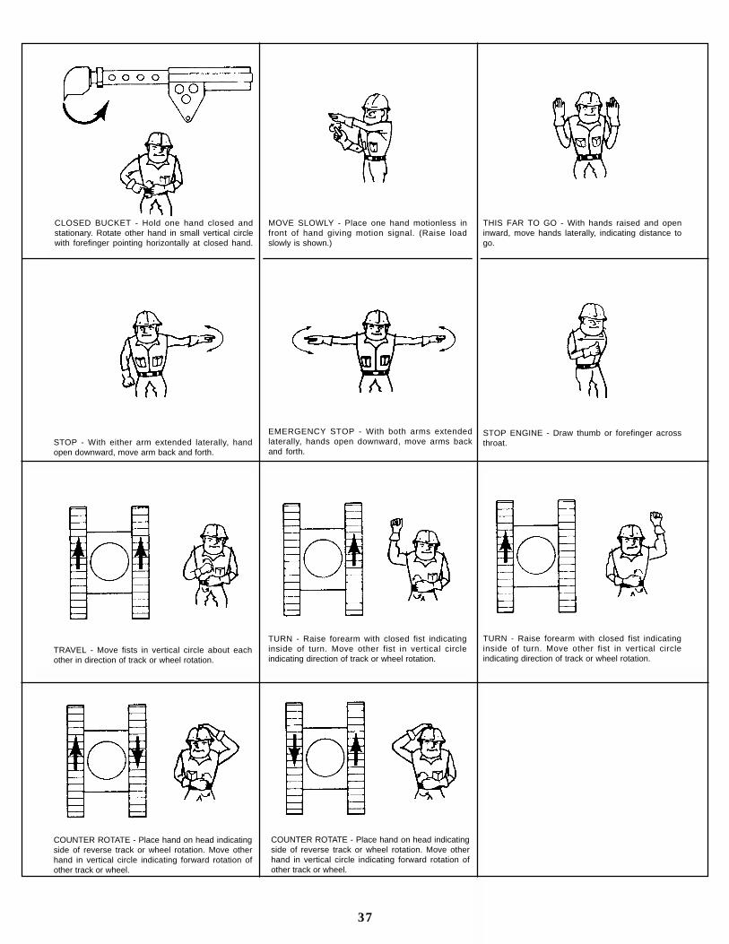
CLOSED BUCKET - Hold one hand closed andstationary. Rotate other hand in small vertical circlewith forefinger pointing horizontally at closed hand.
THIS FAR TO GO - With hands raised and openinward, move hands laterally, indicating distance togo.
STOP - With either arm extended laterally, handopen downward, move arm back and forth.
TRAVEL - Move fists in vertical circle about eachother in direction of track or wheel rotation.
COUNTER ROTATE - Place hand on head indicatingside of reverse track or wheel rotation. Move otherhand in vertical circle indicating forward rotation ofother track or wheel.
37
MOVE SLOWLY - Place one hand motionless infront of hand giving motion signal. (Raise loadslowly is shown.)
EMERGENCY STOP - With both arms extendedlaterally, hands open downward, move arms backand forth.
STOP ENGINE - Draw thumb or forefinger acrossthroat.
TURN - Raise forearm with closed fist indicatinginside of turn. Move other fist in vertical circleindicating direction of track or wheel rotation.
COUNTER ROTATE - Place hand on head indicatingside of reverse track or wheel rotation. Move otherhand in vertical circle indicating forward rotation ofother track or wheel.
TURN - Raise forearm with closed fist indicatinginside of turn. Move other fist in vertical circleindicating direction of track or wheel rotation.
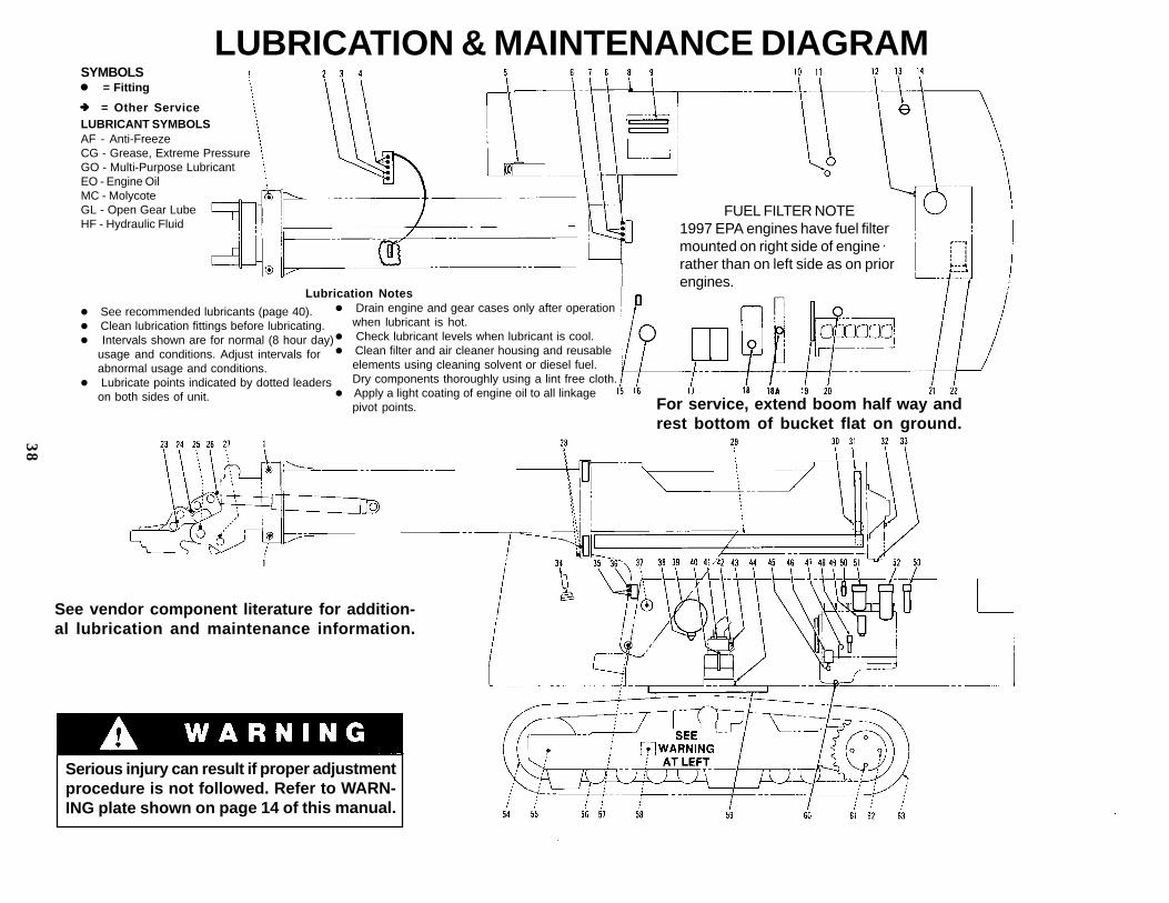
LUBRICATION & MAINTENANCE DIAGRAMSYMBOLSl = Fitting
èèèèè
LUBRICANT SYMBOLSAF - Anti-FreezeCG - Grease, Extreme PressureGO - Multi-Purpose LubricantEO - Engine OilMC - MolycoteGL - Open Gear LubeHF - Hydraulic Fluid
= Other Service
l See recommended lubricants (page 40).l Clean lubrication fittings before lubricating.l Intervals shown are for normal (8 hour day)
usage and conditions. Adjust intervals forabnormal usage and conditions.
l Lubricate points indicated by dotted leaderson both sides of unit.
Serious injury can result if proper adjustmentprocedure is not followed. Refer to WARN-ING plate shown on page 14 of this manual.
FUEL FILTER NOTE1997 EPA engines have fuel filtermounted on right side of enginerather than on left side as on priorengines.
For service, extend boom half way andrest bottom of bucket flat on ground.
See vendor component literature for addition-al lubrication and maintenance information.
l Drain engine and gear cases only after operationwhen lubricant is hot.
l Check lubricant levels when lubricant is cool.l Clean filter and air cleaner housing and reusable
elements using cleaning solvent or diesel fuel.Dry components thoroughly using a lint free cloth.
l Apply a light coating of engine oil to all linkagepivot points.
Lubrication Notes
38
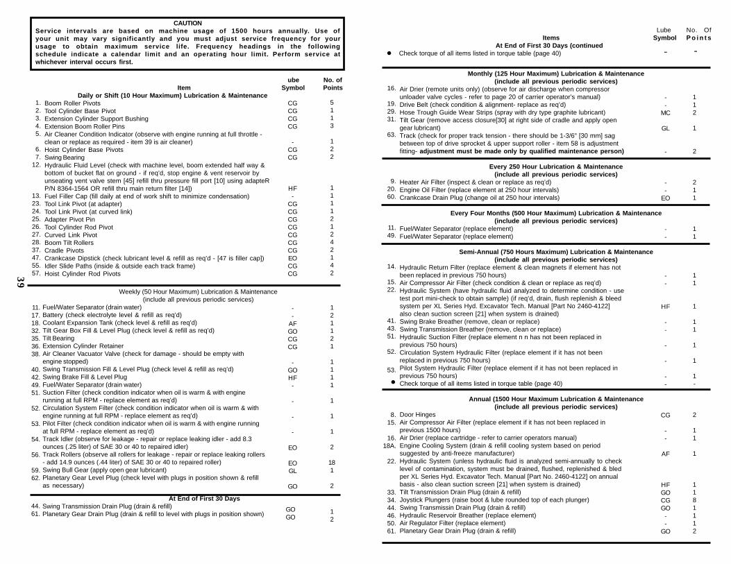
CAUTIONService intervals are based on machine usage of 1500 hours annually. Use ofyour unit may vary significantly and you must adjust service frequency for yourusage to obtain maximum service life. Frequency headings in the followingschedule indicate a calendar limit and an operating hour limit. Perform service atwhichever interval occurs first.
Monthly (125 Hour Maximum) Lubrication & Maintenance(include all previous periodic services)
Air Drier (remote units only) (observe for air discharge when compressorunloader valve cycles - refer to page 20 of carrier operator’s manual)Drive Belt (check condition & alignment- replace as req’d)Hose Trough Guide Wear Strips (spray with dry type graphite lubricant)Tilt Gear (remove access closure[30] at right side of cradle and apply opengear lubricant)Track (check for proper track tension - there should be 1-3/6" [30 mm] sagbetween top of drive sprocket & upper support roller - item 58 is adjustmentfitting- adjustment must be made only by qualified maintenance person)
Every 250 Hour Lubrication & Maintenance(include all previous periodic services)
Heater Air Filter (inspect & clean or replace as req’d)Engine Oil Filter (replace element at 250 hour intervals)Crankcase Drain Plug (change oil at 250 hour intervals)
Every Four Months (500 Hour Maximum) Lubrication & Maintenance(include all previous periodic services)
Fuel/Water Separator (replace element)Fuel/Water Separator (replace element)
Semi-Annual (750 Hours Maximum) Lubrication & Maintenance(include all previous periodic services)
Hydraulic Return Filter (replace element & clean magnets if element has notbeen replaced in previous 750 hours)Air Compressor Air Filter (check condition & clean or replace as req’d)Hydraulic System (have hydraulic fluid analyzed to determine condition - usetest port mini-check to obtain sample) (if req’d, drain, flush replenish & bleedsystem per XL Series Hyd. Excavator Tech. Manual [Part No 2460-4122]also clean suction screen [21] when system is drained)Swing Brake Breather (remove, clean or replace)Swing Transmission Breather (remove, clean or replace)Hydraulic Suction Filter (replace element n n has not been replaced inprevious 750 hours)Circulation System Hydraulic Filter (replace element if it has not beenreplaced in previous 750 hours)Pilot System Hydraulic Filter (replace element if it has not been replaced inprevious 750 hours)Check torque of all items listed in torque table (page 40)
Annual (1500 Hour Maximum Lubrication & Maintenance(include all previous periodic services)
Door HingesAir Compressor Air Filter (replace element if it has not been replaced inprevious 1500 hours)Air Drier (replace cartridge - refer to carrier operators manual)Engine Cooling System (drain & refill cooling system based on periodsuggested by anti-freeze manufacturer)Hydraulic System (unless hydraulic fluid is analyzed semi-annually to checklevel of contamination, system must be drained, flushed, replenished & bledper XL Series Hyd. Excavator Tech. Manual [Part No. 2460-4122] on annualbasis - also clean suction screen [21] when system is drained)Tilt Transmission Drain Plug (drain & refill)Joystick Plungers (raise boot & lube rounded top of each plunger)Swing Transmissin Drain Plug (drain & refill)Hydraulic Reservoir Breather (replace element)Air Regulator Filter (replace element)Planetary Gear Drain Plug (drain & refill)
ube No. ofItem Symbol Points
Daily or Shift (10 Hour Maximum) Lubrication & MaintenanceBoom Roller PivotsTool Cylinder Base PivotExtension Cylinder Support BushingExtension Boom Roller PinsAir Cleaner Condition Indicator (observe with engine running at full throttle -clean or replace as required - item 39 is air cleaner)Hoist Cylinder Base PivotsSwing BearingHydraulic Fluid Level (check with machine level, boom extended half way &bottom of bucket flat on ground - if req’d, stop engine & vent reservoir byunseating vent valve stem [45] refill thru pressure fill port [10] using adapteRP/N 8364-1564 OR refill thru main return filter [14])Fuel Filler Cap (fill daily at end of work shift to minimize condensation)Tool Link Pivot (at adapter)Tool Link Pivot (at curved link)Adapter Pivot PinTool Cylinder Rod PivotCurved Link PivotBoom Tilt RollersCradle PivotsCrankcase Dipstick (check lubricant level & refill as req’d - [47 is filler cap])Idler Slide Paths (inside & outside each track frame)Hoist Cylinder Rod Pivots
1.2.3.4.5.
6.7.
12.
13.23.24.25.26.27.28.37.47.55.57.
CGCGCGCG
-CGCG
HF-
CGCGCGCGCGCGCGEOCGCG
5113
122
111121242142
Weekly (50 Hour Maximum) Lubrication & Maintenance(include all previous periodic services)
Fuel/Water Separator (drain water)Battery (check electrolyte level & refill as req’d)Coolant Expansion Tank (check level & refill as req’d)Tilt Gear Box Fill & Level Plug (check level & refill as req’d)Tilt BearingExtension Cylinder RetainerAir Cleaner Vacuator Valve (check for damage - should be empty withengine stopped)Swing Transmission Fill & Level Plug (check level & refill as req’d)Swing Brake Fill & Level PlugFuel/Water Separator (drain water)Suction Filter (check condition indicator when oil is warm & with enginerunning at full RPM - replace element as req’d)Circulation System Filter (check condition indicator when oil is warm & withengine running at full RPM - replace element as req’d)Pilot Filter (check condition indicator when oil is warm & with engine runningat full RPM - replace element as req’d)Track Idler (observe for leakage - repair or replace leaking idler - add 8.3ounces (.25 liter) of SAE 30 or 40 to repaired idler)Track Rollers (observe all rollers for leakage - repair or replace leaking rollers- add 14.9 ounces (.44 liter) of SAE 30 or 40 to repaired roller)Swing Bull Gear (apply open gear lubricant)Planetary Gear Level Plug (check level with plugs in position shown & refillas necessary)
11.17.18.32.35.36.38.
40.42.49.51.
52.
53.
54.
56.
59.62.
--
AFGOCGCG
-GOHF-
-
-
-
EO
EOGL
GO
121121
1111
1
1
1
2
181
2
At End of First 30 DaysSwing Transmission Drain Plug (drain & refill)Planetary Gear Drain Plug (drain & refill to level with plugs in position shown)
44.61.
GOGO
12
Lube No. Of Items Symbol P o i n t s
At End of First 30 Days (continuedl Check torque of all items listed in torque table (page 40) - -
--
MC
GL
-
--
EO
--
--
HF
--
-
-
--
CG
--
AF
HFGOCGGO
--
GO
112
1
2
211
11
11
1
11
1
1
1-
2
11
1
1181112
39
16.
19.29.31.
63.
9.20.60.
11.49.
14.
15.22.
41.43.51.
52.
53.
l
8.15.
16.18A.
22.
33.34.44.46.50.61.

LUBRICATION & MAINTENANCE
TORQUE CHARTCheck torque using an accurate torque wrench to apply maximum torque value shown. DO NOTEXCEED MAXIMUM TORQUE. Exceeding maximum torque may cause failure of fastener.
Recommended Lubricants & Capacities
Hydraulic Fluid Specifications:Tractor Hydraulic FluidPour Point -46° F.; SSU @ 100° F. 275; Flash Point 442° F.Approved Supplier & Type:Mobile Mobifluid 424 OR Citgo Tractor Hyd. Fluid. #33310
** Specific hydraulic fluid specifications are shown.
*** Capacities are approximate - check level to be sure.
40
