operator affe cara elem - code_aster · code_aster version default titre : opérateur...
TRANSCRIPT

Code_Aster Versiondefault
Titre : Opérateur AFFE_CARA_ELEM Date : 18/04/2018 Page : 1/62Responsable : FLÉJOU Jean-Luc Clé : U4.42.01 Révision :
83eae766c6e6
Operator AFFE_CARA_ELEM
1 Goal
To assign to elements of structure of the geometrical and material characteristics. The affected geometricaldata are complementary to the data of grid.
Among the treated characteristics, let us quote:• for the elements of type hull: the thickness, a direction of reference in the tangent plan,• for the elements of type beam: characteristics of the cross section and orientation of the main axes of
inertia around neutral fibre, curve of the curved elements,• for the elements of the discrete type (arises, mass/inertia, shock absorber): values of the matrices of
rigidity, mass or damping to be affected directly or after orientation,• for the elements of the type bars or of type cables: the surface of the cross section,• for the elements of continuous mediums 3D and 2D: local axes by report in which the user will be able to
define directions of anisotropy.
The order must be exhaustive for all the elements of structure of the model.
This operator produces a structure of the type cara_elem.
Warning : The translation process used on this website is a "Machine Translation". It may be imprecise and inaccurate in whole or in part and isprovided as a convenience.Copyright 2018 EDF R&D - Licensed under the terms of the GNU FDL (http://www.gnu.org/copyleft/fdl.html)

Code_Aster Versiondefault
Titre : Opérateur AFFE_CARA_ELEM Date : 18/04/2018 Page : 2/62Responsable : FLÉJOU Jean-Luc Clé : U4.42.01 Révision :
83eae766c6e6
Contents1 Goal ...................................................................................................................................................... 1
2 General syntax ..................................................................................................................................... 5
3 Operands generals MODEL and VERIF ............................................................................................... 6
3.1 Operand MODEL ........................................................................................................................ 6
3.2 Operand VERIF .......................................................................................................................... 6
3.3 Operand INFORMATION ............................................................................................................ 6
4 Definition of the field of assignment ..................................................................................................... 7
4.1 Operand GROUP_MA ................................................................................................................ 7
5 Assignment of values ........................................................................................................................... 8
6 Keyword BAR ..................................................................................................................................... 10
6.1 Easily affected characteristics .................................................................................................. 10
6.2 Syntax ...................................................................................................................................... 10
6.3 Operands .................................................................................................................................. 10
6.3.1 Operand SECTION = ‘GENERAL’ .................................................................................. 10
6.3.2 Operand SECTION = ‘CIRCLE’ ...................................................................................... 10
6.3.3 Operand SECTION = ‘RIGHT-ANGLED’ ........................................................................ 11
6.4 Operand ‘FCX‘ .......................................................................................................................... 11
7 Keyword CABLE ................................................................................................................................. 12
7.1 Easily affected characteristics .................................................................................................. 12
7.2 Syntax ...................................................................................................................................... 12
7.3 Operand ‘section ‘ ..................................................................................................................... 12
7.4 Operand ‘FCX ‘ ......................................................................................................................... 12
7.5 Operand N_INIT ....................................................................................................................... 12
8 Keyword HULL .................................................................................................................................... 13
8.1 Easily affected characteristics .................................................................................................. 13
8.2 Syntax ...................................................................................................................................... 13
8.3 Operands .................................................................................................................................. 13
8.3.1 Operand THICK .............................................................................................................. 13
8.3.2 Operands OFFSETTING / EXCENTREMENT_FO ........................................................ 13
8.3.3 Operands MODI_METRIQUE / COEF_RIGI_DRZ / INER_ROTA ................................. 14
8.3.4 Operand ANGL_REP/VECTOR ...................................................................................... 14
8.3.5 Operand COQUE_NCOU ............................................................................................... 16
8.3.6 Operand A_CIS .............................................................................................................. 16
8.3.7 Notice on the use of ELAS_COQUE .............................................................................. 16
9 Keyword BEAM ................................................................................................................................... 17
9.1 Easily affected characteristics .................................................................................................. 17
9.2 Syntax ...................................................................................................................................... 17
9.3 Rules of use .............................................................................................................................. 18
9.4 Operands .................................................................................................................................. 19
9.4.1 Operand VARI_SECT ..................................................................................................... 19
9.4.2 Operand MODI_METRIQUE .......................................................................................... 19
9.4.3 Operand SECTION = ‘GENERAL’ .................................................................................. 20
9.4.3.1 Constant section ................................................................................................... 20
9.4.3.2 Homothetic section ............................................................................................... 21
9.4.4 Operand SECTION = ‘RIGHT-ANGLED’ ........................................................................ 23
Warning : The translation process used on this website is a "Machine Translation". It may be imprecise and inaccurate in whole or in part and isprovided as a convenience.Copyright 2018 EDF R&D - Licensed under the terms of the GNU FDL (http://www.gnu.org/copyleft/fdl.html)

Code_Aster Versiondefault
Titre : Opérateur AFFE_CARA_ELEM Date : 18/04/2018 Page : 3/62Responsable : FLÉJOU Jean-Luc Clé : U4.42.01 Révision :
83eae766c6e6
9.4.5 Operand SECTION = ‘CIRCLE’ ...................................................................................... 24
9.4.6 Operand SECTION = ‘ELBOW’ ...................................................................................... 25
9.4.6.1 Operand COEF_FLEX, COEF_FLEX_XZ, COEF_FLEX_XY : coefficients of flexibility ........................................................................................................................... 25
9.4.6.2 Operands INDI_SIGM, INDI_SIGM_XZ, INDI_SIGM_XY : Intensification of the constraints ........................................................................................................................ 26
9.5 Operand FCX ........................................................................................................................... 26
9.6 Operands TUYAU_NSEC / TUYAU_NCOU .............................................................................. 26
10 Keyword ORIENTATION ................................................................................................................... 27
10.1 Easily affected characteristics ................................................................................................ 27
10.2 Syntax .................................................................................................................................... 27
10.3 Rules of use ............................................................................................................................ 28
10.4 Operand CARA = ‘ANGL_NAUT’ ............................................................................................ 28
10.5 Operand CARA = ‘VECT_X_Y’ ............................................................................................... 30
10.6 Operand CARA = ‘ANGL_VRIL’ .............................................................................................. 30
10.7 Operand CARA = ‘VECT_Y’ ................................................................................................... 31
10.8 Operand CARA = ‘GENE_TUYAU’ ......................................................................................... 31
11 Keywords MULTIFIBRE GEOM_FIBRE/ ........................................................................................... 32
11.1 Syntax ..................................................................................................................................... 32
11.2 Goal ........................................................................................................................................ 32
11.3 Keyword MULTIFIBRE ............................................................................................................ 32
11.3.1 Operands GROUP_MA ................................................................................................. 32
11.3.2 Operand GROUP_FIBRE ............................................................................................. 33
11.4 Keyword GEOM_FIBRE ......................................................................................................... 33
11.5 Operands PREC_AIRE / PREC_INERTIE .............................................................................. 33
12 Keyword DISCRETE and DISCRET_2D .......................................................................................... 35
12.1 Easily affected characteristics ................................................................................................ 35
12.2 Syntax .................................................................................................................................... 35
12.3 Operands ................................................................................................................................ 36
12.3.1 Rules of use .................................................................................................................. 36
12.3.2 Operands VALE ............................................................................................................ 36
12.3.3 Operands K_ ( matrices of rigidity) or A_ (matrices of damping) ................................. 37
12.3.4 Operands M_ Matrices of mass .................................................................................... 41
12.3.5 Operand AMOR_HYST ................................................................................................ 46
12.3.6 Operand REFERENCE MARK ..................................................................................... 47
13 Keyword SOLID MASS ..................................................................................................................... 48
13.1 Easily affected characteristics ................................................................................................ 48
13.2 Syntax .................................................................................................................................... 48
13.3 Operand ANGL_REP .............................................................................................................. 48
13.4 Operand ANGL_EULER ......................................................................................................... 48
13.5 Operands ANGL_AXE/ORIG_AXE ......................................................................................... 49
13.6 Example of use ....................................................................................................................... 49
14 Keyword POUTRE_FLUI .................................................................................................................. 50
14.1 Syntax .................................................................................................................................... 50
14.2 Easily affected characteristics ................................................................................................ 50
14.3 Operand GROUP_MA ............................................................................................................ 50
14.4 Operands A_FLUI / A_CELL / COEF_ECHELLE ................................................................... 50
14.5 Operands B_T / B_N / B_TN .................................................................................................. 50
Warning : The translation process used on this website is a "Machine Translation". It may be imprecise and inaccurate in whole or in part and isprovided as a convenience.Copyright 2018 EDF R&D - Licensed under the terms of the GNU FDL (http://www.gnu.org/copyleft/fdl.html)

Code_Aster Versiondefault
Titre : Opérateur AFFE_CARA_ELEM Date : 18/04/2018 Page : 4/62Responsable : FLÉJOU Jean-Luc Clé : U4.42.01 Révision :
83eae766c6e6
15 Keyword GRID .................................................................................................................................. 51
15.1 Syntax .................................................................................................................................... 51
15.2 Easily affected characteristics ................................................................................................ 51
15.3 Description of the operands .................................................................................................... 51
16 Keyword MEMBRANE ...................................................................................................................... 53
16.1 Syntax .................................................................................................................................... 53
16.2 Easily affected characteristics ................................................................................................ 53
16.3 Description of the operands .................................................................................................... 54
17 Keyword RIGI_PARASOL ................................................................................................................. 55
17.1 Syntax .................................................................................................................................... 55
17.2 Easily affected characteristics ................................................................................................ 55
17.3 Description of the operands .................................................................................................... 56
17.4 Principle of determination of the characteristics of the discrete elements ............................. 56
17.5 Example of use ....................................................................................................................... 57
18 Keyword RIGI_MISS_3D .................................................................................................................. 59
18.1 Syntax .................................................................................................................................... 59
18.2 Easily affected characteristics ................................................................................................ 59
18.3 Description of the operands .................................................................................................... 59
19 Keyword MASS_AJOU ..................................................................................................................... 60
19.1 Syntax .................................................................................................................................... 60
19.2 Easily affected characteristics ................................................................................................ 60
19.3 Description of the operands .................................................................................................... 60
20 Keyword MASS_REP ....................................................................................................................... 61
20.1 Syntax .................................................................................................................................... 61
20.2 Easily affected characteristics ................................................................................................ 61
20.3 Description of the operands .................................................................................................... 61
Warning : The translation process used on this website is a "Machine Translation". It may be imprecise and inaccurate in whole or in part and isprovided as a convenience.Copyright 2018 EDF R&D - Licensed under the terms of the GNU FDL (http://www.gnu.org/copyleft/fdl.html)

Code_Aster Versiondefault
Titre : Opérateur AFFE_CARA_ELEM Date : 18/04/2018 Page : 5/62Responsable : FLÉJOU Jean-Luc Clé : U4.42.01 Révision :
83eae766c6e6
2 General syntax
will cara [cara_elem] = AFFE_CARA_ELEM ( ♦ MODEL = Mo [model] ◊ INFORMATION = [1, 2] [defect] ◊ VERIF = ‘MESH’,
♦ | BAR = to see keyword BARS [§6]
| CABLE = to see keyword CABLES [§7]
| HULL = to see keyword HULL [§8]
| BEAM = to see keyword BEAM [§9] ◊ ORIENTATION = to see keyword ORIENTATION [§10]
| MULTIFIBRE = to see keyword MULTI_FIBRE [§11.3] ◊ GEOM_FIBRE = to see keyword GEOM_FIBRE [§11.4]
| DISCRETE = to see DISCRETE keyword [§12] ◊ ORIENTATION = to see keyword ORIENTATION [§10]
| DISCRET_2D = to see keyword DISCRET_2D [§12] ◊ ORIENTATION = to see keyword ORIENTATION [§10]
| SOLID MASS = to see MASSIVE keyword [§13]
| POUTRE_FLUI = to see keyword POUTRE_FLUI [§14]
| GRID = to see keyword ROASTS [§15]
| MEMBRANE = to see keyword MEMBRANE [§16]
| RIGI_PARASOL = to see keyword RIGI_PARASOL [§17]
| RIGI_MISS_3D = to see keyword RIGI_MISS_3D [§18]
| MASS_AJOU = to see keyword MASS_AJOU [§19]
| MASS_REP = to see keyword MASS_REP [§20])
Warning : The translation process used on this website is a "Machine Translation". It may be imprecise and inaccurate in whole or in part and isprovided as a convenience.Copyright 2018 EDF R&D - Licensed under the terms of the GNU FDL (http://www.gnu.org/copyleft/fdl.html)

Code_Aster Versiondefault
Titre : Opérateur AFFE_CARA_ELEM Date : 18/04/2018 Page : 6/62Responsable : FLÉJOU Jean-Luc Clé : U4.42.01 Révision :
83eae766c6e6
3 Operands generals MODEL and VERIF
3.1 Operand MODEL♦ MODEL = MoConcept of the type model, produced by the operator AFFE_MODELE [U4.41.01] on which thecharacteristics of the elements are affected. Let us note that the model must contain explicitly at leastone of the elements of structure, on which will carry the assignment (if not calculation stops).
3.2 Operand VERIF◊ VERIF =/ ‘MESH’
Argument Significance
‘MESH’
Check that the type of element supported by the meshs, to which one wantsto affect a characteristic, is compatible with this characteristic (including theorientations).In the contrary case, stop with error message.
3.3 Operand INFORMATION◊ INFORMATION=/1
Do not print anything
/ 2 Print on the file “MESSAGE”, for all the elements, the list of values assignedto the elements:• angles of orientation in degrees (beams and discrete),• characteristics of the cross sections of beams and bars,• impressions of the elementary matrices (discrete).
Warning : The translation process used on this website is a "Machine Translation". It may be imprecise and inaccurate in whole or in part and isprovided as a convenience.Copyright 2018 EDF R&D - Licensed under the terms of the GNU FDL (http://www.gnu.org/copyleft/fdl.html)

Code_Aster Versiondefault
Titre : Opérateur AFFE_CARA_ELEM Date : 18/04/2018 Page : 7/62Responsable : FLÉJOU Jean-Luc Clé : U4.42.01 Révision :
83eae766c6e6
4 Definition of the field of assignmentThe choice of the elements of the model Mo to which relates the assignment is done in two stages:• the choice of the type of element concerned with the assignment (BEAM, DISCRETE,…),• meshs (of the type of definite element) to affect.The choice of the keyword factor defining the type of elements (BEAM, DISCRETE,…) imply that thereexists in the model the types of adapted elements (checking carried out systematically).
The types of elements concerned depend on modeling:• phenomenon MECHANICSKeyword ModelingBAR BAR, CABLE_GAINECABLE CABLE, CABLE_POULIE
HULLCOQUE_AXIS, COQUE_C_PLAN, COQUE_D_PLAN, DKT, DST, DKQ, DSQ,Q4G, COQUE_3D, DKTG, Q4GG
DISCRETE DIS_T, DIS_TR, 2D_DIS_T, 2D_DIS_TR
BEAMPOU_D_E, POU_D_T, POU_D_TG, POU_D_T_GD, FLUI_STRU, TUYAU_3M,TUYAU_6M, POU_D_EM, POU_D_TGM
SOLID MASS 3D, AXIS, AXIS_FOURIER, C_PLAN, D_PLAN, TUYAU_3M, TUYAU_6MGRID GRILLE_EXCENTRE, GRILLE_MEMBRANEMEMBRANE MEMBRANEPOUTRE_FLUI 3D_FAISCEAUMULTI_FIBRE POU_D_EM, POU_D_TGMRIGI_PARASOL DIS_TRRIGI_MISS_3D DIS_T
• phenomenon THERMICSKeyword ModelingHULL COQUE_AXIS, COQUE_PLAN, HULLSOLID MASS 3D, AXIS, PLAN
The assignment of the characteristics to the finite elements is done with the assistance DU keyword:‘GROUP_MA’.• If VERIF is not present: in a group of meshs (or nodes), one assigns indeed the characteristics to
the only elements for which they have a direction. For the other elements, the characteristics arenot affected.
• If VERIF is present: one checks moreover than all the elements of the group are of the good type,if not an error message is transmitted.
4.1 Operand GROUP_MAOperands Significance
GROUP_MA = lgma Assignment with all the elements of the groups of meshs specified.
As in the other orders, the rule of overload applies [U1.03.00].
Warning : The translation process used on this website is a "Machine Translation". It may be imprecise and inaccurate in whole or in part and isprovided as a convenience.Copyright 2018 EDF R&D - Licensed under the terms of the GNU FDL (http://www.gnu.org/copyleft/fdl.html)

Code_Aster Versiondefault
Titre : Opérateur AFFE_CARA_ELEM Date : 18/04/2018 Page : 8/62Responsable : FLÉJOU Jean-Luc Clé : U4.42.01 Révision :
83eae766c6e6
5 Assignment of valuesTwo methods are usable to affect values of characteristics:• classical method: operand whose name evokes the treated characteristic followed by a value or a
list of values. Examples:HULL = _F (THICK = 1.E-2, GROUP_MA = ‘G1’),HULL = _F (ANGL_REP = (0. , 90.), GROUP_MA = ‘G2’),
• for the assignments concerning BAR, BEAM and DISCRETE, like ORIENTATION for the elementsof beam and the elements discrete, a large number of characteristics being able to be affected ledto a better adapted syntax:
CARA = (…) # lists names of characteristicsVALE = (…) # lists values corresponding to the characteristics
One gives below an example to illustrate this case.
Description of the meshs: SEG2 M1 N1 N2 M2 N2 N3 M3 N3 N4 M4 N5 N4 M5 N5 N6 M6 N6 N7 FINSF
Command file:= AFFE_CARA_ELEM will cara ( POUTRE= ( _F (SECTION=' CERCLE', CARA= (‘R’, ‘EP’), VALE= (0.1, 0.02),GROUP_MA= (‘M1’,‘M5’)), _F (SECTION=' CERCLE', CARA= (‘R’, ‘EP’), VALE= (0.2, 0.05),GROUP_MA= ‘m3’), _F (SECTION=' CERCLE', CARA= (‘R’, ‘EP’), VALE= (0.09, 0.01),GROUP_MA=‘M6’), _F (SECTION=' CERCLE', CARA= (‘R1’, ‘R2’), VALE= (0.1, 0.2),GROUP_MA= (‘M2’,‘M4’)), _F (SECTION=' CERCLE', CARA= (‘EP1’, ‘EP2’), VALE= (0.02, 0.05),GROUP_MA=(‘M2’, ‘M4’)), ),)
Warning : The translation process used on this website is a "Machine Translation". It may be imprecise and inaccurate in whole or in part and isprovided as a convenience.Copyright 2018 EDF R&D - Licensed under the terms of the GNU FDL (http://www.gnu.org/copyleft/fdl.html)

Code_Aster Versiondefault
Titre : Opérateur AFFE_CARA_ELEM Date : 18/04/2018 Page : 9/62Responsable : FLÉJOU Jean-Luc Clé : U4.42.01 Révision :
83eae766c6e6
It is possible to use the features of the language python. The example below recovers sizes calculatedby the order MACR_CARA_POUTRE, for then affecting them. The use of python requires to putPAR_LOT=‘NOT’ in the order BEGINNING.
PRE_GIBI ()SECTION = MACR_CARA_POUTRE (NOEUD= ‘N1’, GROUP_MA_BORD= ‘EDGE’)
II = 2alpha0 = SECTION [‘ALPHA’, II]cdgx0 = SECTION [‘CDG_X’, II]cdgy0 = SECTION [‘CDG_Y’, II]AIRE0 = SECTION [‘SURFACE’, II]IY0 = SECTION [‘IY_PRIN_G’, II]IZ0 = SECTION [‘IZ_PRIN_G’, II]EY0 = SECTION [‘EY’, II]EZ0 = SECTION [‘EZ’, II]JX0 = SECTION [‘CT’, II]JG0 = SECTION [‘JG’, II]AY0 = SECTION [‘AY’, II]AZ0 = SECTION [‘AZ’, II]IYR20 = SECTION [‘IYR2_PRIN_G’, II]IZR20 = SECTION [‘IZR2_PRIN_G’, II]
carelem=AFFE_CARA_ELEM (MODELE=mod, BEAM = ( _F (GROUP_MA= (‘POUT1’, ‘POUT2’), SECTION=' GENERALE', CARA= (‘WITH’, ‘IY’, ‘IZ’, ‘AY’, ‘AZ’, ‘EY’, ‘EZ’, ‘JX’, ‘JG’, ‘IYR2’, ‘IZR2’), VALE= ( AIRE0, IY0, IZ0, AY0, AZ0, EY0, EZ0, JX0, JG0, IYR20, IZR20),), ) )
If grid SECTION contains a surface group of mesh named ‘SQUARES’, it is possible to directly use thetable resulting from MACR_CARA_POUTRE in the following way:
SECTION = MACR_CARA_POUTRE (MAILLAGE=mail, NOEUD= ‘N1’, GROUP_MA_BORD= ‘EDGE’)
carelem=AFFE_CARA_ELEM (MODELE=mod, BEAM = ( _F (GROUP_MA= (‘POUT1’, ‘POUT2’), SECTION=' GENERALE', TABLE_CARA=SECTION, NOM_SEC=' CARRE', ) )
Warning : The translation process used on this website is a "Machine Translation". It may be imprecise and inaccurate in whole or in part and isprovided as a convenience.Copyright 2018 EDF R&D - Licensed under the terms of the GNU FDL (http://www.gnu.org/copyleft/fdl.html)

Code_Aster Versiondefault
Titre : Opérateur AFFE_CARA_ELEM Date : 18/04/2018 Page : 10/62Responsable : FLÉJOU Jean-Luc Clé : U4.42.01 Révision :
83eae766c6e6
6 Keyword BAR
6.1 Easily affected characteristicsAllows to affect the characteristics of the cross sections of elements of the type BAR or CABLE_GAINE.One can treat three types of cross sections defined by the operand SECTION.With each type of section, it is possible to affect various characteristics identified by one or morenames (operand CARA) which one associates as many values (operand VALE). It is also possible togive the characteristics via a table in the case of the general section, to see the documentation of theorder MACR_CARA_POUTRE.
6.2 SyntaxBAR = _F ( ♦ GROUP_MA = lgma, [l_gr_maille]
# general constant section ♦/SECTION = ‘GENERAL’, ♦/TABLE_CARA = will tb_cara, [sd_table] NOM_SEC = nom_sec, [K8] / CARA = ‘with’, VALE = goes, [l_réel] # constant section right-angled / SECTION = ‘RIGHT-ANGLED’, ♦ CARA =/[‘H’|' EP'], / [‘HY’|' HZ'|' EPY'|' EPZ'], ♦ VALE = goes, [l_réel] # constant section rings / SECTION = ‘CIRCLE’, ♦ CARA = [‘R’|' EP'], ♦ VALE = goes, [l_réel] ◊ FCX = fv, [FUNCTION]),
Rule of use:One cannot overload a kind of section (CIRCLE, RECTANGLE, GENERAL) by another.
6.3 Operands6.3.1 Operand SECTION = ‘GENERAL’
The only characteristic required in this case is the surface of the cross section of the bar ‘With’. Itcan be read in a table (keywords TABLE_CARA and NOM_SEC, to see §9.4.3.1).
6.3.2 Operand SECTION = ‘CIRCLE’
CARA Significance Value by defaultR Ray external of the tube ObligatoryEP Thickness in the case of a hollow tube Full tube (EP=R)
Warning : The translation process used on this website is a "Machine Translation". It may be imprecise and inaccurate in whole or in part and isprovided as a convenience.Copyright 2018 EDF R&D - Licensed under the terms of the GNU FDL (http://www.gnu.org/copyleft/fdl.html)

Code_Aster Versiondefault
Titre : Opérateur AFFE_CARA_ELEM Date : 18/04/2018 Page : 11/62Responsable : FLÉJOU Jean-Luc Clé : U4.42.01 Révision :
83eae766c6e6
Figure 6.3.2-1 : Section of the type CIRCLE.
These values are used to calculate the surface A section.
6.3.3 Operand SECTION = ‘RIGHT-ANGLED’
CARA Significance Value by default/ HY Dimension of the following rectangle GY Obligatory HZ Dimension of the following rectangle GZ Obligatory/ H Length of the edge (if the rectangle is square) Obligatory/ EPY Thickness according to GY in the case of a hollow tube HY/2 EPZ Thickness according to GZ in the case of a hollow tube HZ/2/ EP Thickness along the two axes in the case of a hollow tube Full tube
Figure 6.3.3-1 : Section of the type RECTANGLE.
Rules of use: for a given mesh• ‘H’ is incompatible with ‘HZ’ and ‘HY’• ‘EP’ is incompatible with ‘EPY’ and ‘EPZ’.
6.4 Operand ‘FCX‘◊ FCX = fvAssignment of a function describing the dependence of the force distributed with respect to therelative speed of wind (see for example [V6.02.118]).
Warning : The translation process used on this website is a "Machine Translation". It may be imprecise and inaccurate in whole or in part and isprovided as a convenience.Copyright 2018 EDF R&D - Licensed under the terms of the GNU FDL (http://www.gnu.org/copyleft/fdl.html)

Code_Aster Versiondefault
Titre : Opérateur AFFE_CARA_ELEM Date : 18/04/2018 Page : 12/62Responsable : FLÉJOU Jean-Luc Clé : U4.42.01 Révision :
83eae766c6e6
7 Keyword CABLE
7.1 Easily affected characteristicsAllows to assign a constant section to the elements of the type cables or cable-pulley.
7.2 SyntaxCABLE = _F ( ♦ GROUP_MA = lgma, [l_gr_maille] ♦ SECTION = surface, [reality] ◊ FCX = fv, [function] ♦ N_INIT = ninit, [reality]),
7.3 Operand ‘SECTION ‘♦ SECTION = surfaceAllows to define the surface of the cross section of the cable.
7.4 Operand ‘FCX ‘◊ FCX = fvAssignment of a function describing the dependence of the force distributed with respect to therelative speed of wind (HM-77/01/046) to see for example test SDNL102 [V5.02.102].
7.5 Operand N_INITAllows to define the initial tension in the cable.
Warning : The translation process used on this website is a "Machine Translation". It may be imprecise and inaccurate in whole or in part and isprovided as a convenience.Copyright 2018 EDF R&D - Licensed under the terms of the GNU FDL (http://www.gnu.org/copyleft/fdl.html)

Code_Aster Versiondefault
Titre : Opérateur AFFE_CARA_ELEM Date : 18/04/2018 Page : 13/62Responsable : FLÉJOU Jean-Luc Clé : U4.42.01 Révision :
83eae766c6e6
8 Keyword HULL
8.1 Easily affected characteristicsThe characteristics which one can affect on the elements of plate or hull are:• for all the elements of this type, a constant thickness on each mesh, since the grid represents only
the average layer (or of diagram for offset),• for all the elements of this type, the number of layers used for integration in the thickness,• for all the elements of this type, the orientation of the specific local reference mark to each mesh,• for certain models of hull, particular characteristics: coefficient of shearing, metric, offsetting, etc.
8.2 SyntaxHULL = _F ( ♦ GROUP_MA = lgma, [l_gr_maille]
THICK ♦/ = ep, [reality] / EPAIS_FO = epfct [function]
◊/ANGL_REP =/(0.0,0.0), [defect] / ( , ), [l_réel] / VECTOR = (vx, vy, vz), [l_réel]
◊ MODI_METRIQUE = [‘NOT‘|’ OUI'], [defect)] ◊ COEF_RIGI_DRZ = KRZ (1.E-5), [reality (defect)] ◊ OFFSETTING = E (0.0), [reality (defect)] EXCENTREMENT_FO = efct [function]
◊ INER_ROTA = ‘YES’, ◊ A_CIS = kappa (0.8333333), [reality (defect)] ◊ COQUE_NCOU = N (1), [entirety (defect)])
8.3 Operands8.3.1 Operand THICK
THICK ♦/ = ep / EPAIS_FO = epfctTHICK represent the thickness of the hull which must be expressed in the same units as thecoordinates of the nodes of the grid.EPAIS_FO is a function which gives the thickness of the hull, in the same units as the coordinates ofthe nodes of the grid. This function depends on geometry (X, Y, Z) and is evaluated in the centre ofgravity of the mesh.
8.3.2 Operands OFFSETTING / EXCENTREMENT_FO
◊ OFFSETTING = / E (0.0), [reality (defect)] EXCENTREMENT_F0 = efct [ function ]
OFFSETTING: to define the distance enters surface with a grid and average surface, in the directionof the normal (modelings DKT, DST, GRILLE_EXCENTRE).EXCENTREMENT_FO: Function which gives the distance between surface with a grid and averagesurface, in the direction of the normal (modelings DKT, DST, GRILLE_EXCENTRE). This functiondepends on geometry (X, Y, Z) and is evaluated in the centre of gravity of the mesh.
Warning : The translation process used on this website is a "Machine Translation". It may be imprecise and inaccurate in whole or in part and isprovided as a convenience.Copyright 2018 EDF R&D - Licensed under the terms of the GNU FDL (http://www.gnu.org/copyleft/fdl.html)

Code_Aster Versiondefault
Titre : Opérateur AFFE_CARA_ELEM Date : 18/04/2018 Page : 14/62Responsable : FLÉJOU Jean-Luc Clé : U4.42.01 Révision :
83eae766c6e6
The taking into account of offsetting influences the behavior of inflection and possibly the behavior ofmembrane in the presence of coupling (there is no effect on shearing).
8.3.3 Operands MODI_METRIQUE / COEF_RIGI_DRZ / INER_ROTA
◊ MODI_METRIC = ‘NOT’Fact the assumption that the thickness of the element is low. During integrations in the thickness onedoes not take account of the variation of the radius of curvature (option by default for all the hulls).
◊ MODI_METRIC = ‘YES’For modelings of thick hulls: COQUE_AXIS, COQUE_C_PLAN, COQUE_D_PLAN, COQUE_3D, integrationsare done by taking of account the variations of the radius of curvature according to the thickness, tosee for example [R3.07.02], [R3.07.04].
◊ INER_ROTA = ‘YES’Taking into account of the inertia of rotation for modeling DKT, DST and Q4G. It is obligatory in theevent of offsetting. One can omit this keyword for thin hulls, where the terms of inertia of rotation arenegligible compared to different in the matrix of mass [R3.07.03].
◊ COEF_RIGI_DRZ = KRZ,KRZ is a coefficient of fictitious rigidity (necessarily small) on the degree of freedom of rotation aroundthe normal with the hull. It is necessary to prevent that the matrix of rigidity is singular, but must beselected smallest possible. The value by default of 10−5 is appropriate for most situations (it is arelative value: rigidity around the normal is equal to KRZ time the diagonal minor term of the matrix ofrigidity of the element). For the DKT, there are two operating processes. COEF_RIGI_DRZ negativeand COEF_RIGI_DRZ positive. In the case COEF_RIGI_DRZ positive, it degree of freedom DRZalways a direction of fictitious rotation has which prevents the matrix from being singular in the totalreference mark. In the case of one COEF_RIGI_DRZ negative, one reinforces by a variational writingthe kinematics of rotation of the element plates around his normal. degree of freedom DRZ thus has aphysical direction. One advises a value of 10−8 .
Note:Attention, in STAT/DYNA_NON_LINE, this coefficient can involve additional iterations of Newton (morethan one iteration for a linear problem for example).
8.3.4 Operand ANGL_REP/VECTOR
Keywords ANGL_REP or VECTOR allow to inform to the reference mark “user” in each element of hull.It is in this reference mark that for example the constraints in the generalized hull or efforts areexpressed [U2.01.05].The user provides using these keywords a vector V who will allow to entirely define the reference
mark. The construction of this reference mark “user” from V is carried out in any point P in thefollowing way (cf Appears 8.3.4-1):
• the projection of V on the tangent level provides the axis xl ,• the vector zl is colinéaire with the normal n with the plan of the hull which is known for each
element, its orientation can be changed by MODI_MAILLAGE/ORIE_NORM_COQUE [U4.23.04],
• the vector y l is built so as to have an orthonormal reference mark.
Warning : The translation process used on this website is a "Machine Translation". It may be imprecise and inaccurate in whole or in part and isprovided as a convenience.Copyright 2018 EDF R&D - Licensed under the terms of the GNU FDL (http://www.gnu.org/copyleft/fdl.html)

Code_Aster Versiondefault
Titre : Opérateur AFFE_CARA_ELEM Date : 18/04/2018 Page : 15/62Responsable : FLÉJOU Jean-Luc Clé : U4.42.01 Révision :
83eae766c6e6
The reference mark “user” is thus: (P , x l , y l , zl) with: z l=n and y l=zl ^ xl
Figure 8.3.4-1: Definition of the reference mark user of a hull
Keywords ANGL_REP and VECTOR are exclusive, the vector V is defined using one or other.
◊ ANGL_REP = ( , )
The keyword ANGL_REP the vector defines V in the total reference mark O , X ,Y , Z starting
from two nautical angles and as explained Figure 8.3.4-2 and Appears 8.3.4-3.
Figure 8.3.4-2 : Representation of the angle
Rotation around OZ transform OXYZ in
OX 1Y 1Z with Z 1≡ Z .
Figure 8.3.4-3 : Representation of the angle
Rotation around OY 1 transform OX 1 in
OX 2 . Note: on the figure the angle is negative.
Warning : The translation process used on this website is a "Machine Translation". It may be imprecise and inaccurate in whole or in part and isprovided as a convenience.Copyright 2018 EDF R&D - Licensed under the terms of the GNU FDL (http://www.gnu.org/copyleft/fdl.html)

Code_Aster Versiondefault
Titre : Opérateur AFFE_CARA_ELEM Date : 18/04/2018 Page : 16/62Responsable : FLÉJOU Jean-Luc Clé : U4.42.01 Révision :
83eae766c6e6
In three-dimensional representation, the vector is obtained as follows [Figure 8.3.4-4].
Figure 8.3.4-4 : Representation 3D of the vector V defined by ANGL_REP
◊ VECTOR = vx , vy , vz The vector V is defined by its coordinates in the reference mark total O , X ,Y , Z .
Note:• If none the keywords above is indicated, it is thus the total axis X who determines, by
projection on the tangent level of the hull, the reference mark “user” of each mesh. • The reference mark “user” is also used for the definition of the orientation of fibres in the
composite hulls ( DEFI_COMPOSITE , [U4.42.03] ).
8.3.5 Operand COQUE_NCOU
◊ COQUE_NCOU = / N (1), [entirety, defect]It is amongst layers used for integration in the thickness the hull. The number of layers alsodetermines the number of under-points of the stress field: 2n+1 .Into non-linear, it is necessary to use more than one layer to correctly integrate the constraints in thethickness, cf. [U2.02.01].
8.3.6 Operand A_CIS
◊ A_CIS = / kappa (0.8333333), [reality, defect]This parameter is to be used if one wishes, for a thick hull to be within the framework of the modelCoils-Kirchhoff. It is applicable only for modelings COQUE_C_PLAN, COQUE_D_PLAN, COQUE_AXISand COQUE_3D. For more detail the user will refer to the note [U2.02.01].
8.3.7 Notice on the use of ELAS_COQUE
When one uses ELAS_COQUE Lbe stiffnesses of inflection and of membrane returned to the hand bythe user in DEFI_MATERIAU. In it case, the thickness informed in AFFE_CARA_ELEM is only used tocalculate the mass in dynamics and does not contribute to the stiffness.
Warning : The translation process used on this website is a "Machine Translation". It may be imprecise and inaccurate in whole or in part and isprovided as a convenience.Copyright 2018 EDF R&D - Licensed under the terms of the GNU FDL (http://www.gnu.org/copyleft/fdl.html)

Code_Aster Versiondefault
Titre : Opérateur AFFE_CARA_ELEM Date : 18/04/2018 Page : 17/62Responsable : FLÉJOU Jean-Luc Clé : U4.42.01 Révision :
83eae766c6e6
9 Keyword BEAM
9.1 Easily affected characteristicsThis keyword makes it possible to affect the characteristics of the cross sections of elements of thetype beam (modelings POU_D_E, POU_D_EM, POU_D_T, POU_D_TG, POU_D_TGM, POU_D_T_GD,TUYAU_3M, TUYAU_6M).One can treat several types of sections defined by the operand SECTION :• GENERAL : The mechanical characteristics are given.• RECTANGLE : Dimensions of the section are given. Code_Aster calculate the mechanical
characteristics necessary: surface, inertias,…• CIRCLE : Dimensions of the section are given. Code_Aster calculate the mechanical
characteristics necessary: surface, inertias,…• ELBOW : Is used to define the coefficients of correction of inertias and amplification of the
constraints if one wishes to take account of the ovalization of the section, which cannot be takeninto account by the theory of the beams. The mechanical characteristics are given by SECTIONwho can take the value GENERAL or RECTANGLE or CIRCLE.
With each type of section, it is possible to affect various characteristics identified by one or morenames (operand CARA) which one associates as many values (operand VALE). It is also possible togive the characteristics via a table in the case of the general section, to see the documentation of theorder MACR_CARA_POUTRE.It is possible to treat beams of constant section (name of characteristic without suffix) or of variablesection (name of characteristic with suffix 1 or 2). The mode of variation of the section is defined bythe keyword VARI_SECT (cf [§9.4.1]). One then gives the characteristics of the section to the initialnode (name with suffix 1) and with the final node (name with suffix 2) (“initial” and “final” compared tothe classification of the mesh support). One must also use this keyword to define the constant oftorsion for modeling (POU_D_EM).
9.2 SyntaxBEAM = _F ( ♦ GROUP_MA = lgma, [l_gr_maille] # general section ♦/SECTION = ‘GENERAL’, ◊ VARI_SECT = [‘CONSTANT‘,’ HOMOTHETIQUE'] [defect] # constant general section / ♦ TABLE_CARA = will tb_cara, [sd_table] ♦ NOM_SEC = nom_sec, [K8] / ♦ CARA = |' A'|' IY'|' IZ'|' AY'|' AZ'|' EY'|' EZ', |' JX'|' AI'|' RY'|' RZ'|' RT', |' JG'|' IYR2'|' IZR2', ♦ VALE = goes, [l_réel] # homothetic general section / ♦ CARA = |' A1'|' A2'|' IY1'|' IY2'|' IZ1'|' IZ2', |' JX1'|' JX2'|' AY1'|' AY2'|' AZ1'|' AZ2', |' JG1'|' JG2'|' EY1'|' EY2'|' EZ1'|' EZ2', |' AI1'|' AI2'|' RY1'|' RY2'|' RZ1'|' RZ2', |' RT1'|' RT2'|' IYR21'|' IZR21', |' IYR22'|' IZR22', ♦ VALE = goes, [l_réel]
Warning : The translation process used on this website is a "Machine Translation". It may be imprecise and inaccurate in whole or in part and isprovided as a convenience.Copyright 2018 EDF R&D - Licensed under the terms of the GNU FDL (http://www.gnu.org/copyleft/fdl.html)

Code_Aster Versiondefault
Titre : Opérateur AFFE_CARA_ELEM Date : 18/04/2018 Page : 18/62Responsable : FLÉJOU Jean-Luc Clé : U4.42.01 Révision :
83eae766c6e6
# section right-angled / SECTION = ‘RIGHT-ANGLED’, ◊ VARI_SECT = [‘CONSTANT‘,’ HOMOTHETIQUE' ‘REFINES’], [defect] # constant right-angled section / ♦ CARA =/ |' H'|' EP', / |‘HY'|' HZ'|' EPY'|' EPZ', ♦ VALE = goes, [l_réel] # homothetic right-angled section / ♦ CARA =/ |' H1'|' H2'|' EP1'|' EP2', / |' HY1'|' HZ1'|' HY2'|' HZ2', |' EPY1'|' EPY2'|' EPZ1'|' EPZ2', ♦ VALE = goes, [l_réel] # right-angled section closely connected / ♦ CARA = |' HY'|' EPY'|' HZ1',|' EPZ1'|' HZ2'|' EPZ2', ♦ VALE = goes, [l_réel]
# section rings / SECTION = ‘CIRCLE’, ◊ VARI_SECT = [‘CONSTANT‘,’ HOMOTHETIQUE'], [defect] # section circle constant / ♦ CARA = |' R'|' EP', ♦ VALE = goes, [l_réel] # section circle homothetic on GROUP_MA / ♦ CARA = |' R_DEBUT'|' R_FIN'|' EP_DEBUT'|' EP_FIN', ♦ VALE = goes, [l_réel] # section bends / SECTION = ‘ELBOW’, ◊ / ◊ COEF_FLEX = cflex, [reality] / ♦ COEF_FLEX_XY = cflex_xy, [reality] ♦ COEF_FLEX_XZ = cflex_xz, [reality] ◊/◊ INDI_SIGM = isigm, [reality] / ♦ INDI_SIGM_XY = isigm_xy, [reality] ♦ INDI_SIGM_XZ = isigm_xz, [reality] ◊ MODI_METRIQUE = [‘YES’, ‘NOT’], [defect] ◊ TUYAU_NSEC = nsec (16), [entirety (defect)] ◊ TUYAU_NCOU = ncou (3), [entirety (dieis necessary)] ◊ FCX = fv, [function]),
9.3 Rules of useNote:
The orientation of the elements of beams is done by the keyword ORIENTATION [§10]. The angleof gimlet (which makes it possible to direct the transverse section of the beam around its neutralfibre) is always given to direct the main axes of the section what is not very practical, becausethese axes are in general unknown before the calculation of the geometrical characteristics of thesection, cf. MACR_CARA_POUTRE [U4.42.02].
• It is possible to provide via variables python, the characteristics of the sections (general)resulting from a calculation with MACR_CARA_POUTRE (Cf the test SSLL107F ).
• Various names of characteristics of the arguments of the operand CARA are described further foreach argument of the operand SECTION.
• For a given mesh:◦ One cannot overload a kind of variation of section (constant or variable) by another.◦ One cannot overload a kind of section ( CIRCLE , RECTANGLE , GENERAL ) by another.◦ For the beams non-prismatic, the names with suffix 1 or 2 are incompatible with the names
without suffix. Example: A is incompatible with A1 and A2 .
Warning : The translation process used on this website is a "Machine Translation". It may be imprecise and inaccurate in whole or in part and isprovided as a convenience.Copyright 2018 EDF R&D - Licensed under the terms of the GNU FDL (http://www.gnu.org/copyleft/fdl.html)

Code_Aster Versiondefault
Titre : Opérateur AFFE_CARA_ELEM Date : 18/04/2018 Page : 19/62Responsable : FLÉJOU Jean-Luc Clé : U4.42.01 Révision :
83eae766c6e6
◦ H is incompatible with HZ and HY (like H1 , H2 ,…)◦ EP is incompatible with EPY and EPZ (like EP1 , EP2 ,…).◦ RY , RZ and RT intervene only for the calculation of the constraints.
9.4 Operands9.4.1 Operand VARI_SECT
Allows to define the type of variation of section between the two nodes ends of the element of beam,elements POU_D_E and POU_D_T [R3.08.01].The possibilities are:Section Closely connected Homotheticcircle not yesrectangle yes (according to y ) yesgeneral not yes
• “Refines” mean that the surface of the section varies in a linear way between the two nodes.
Dimensions in the direction are constant there ( HY , EPY ) and that in the direction z varylinearly ( HZ1 , HZ2 , EPZ1 , EPZ2 ).
• “Homothetic” mean that dimensions of the section vary linearly between the values given tothe two nodes ends. In this case, the surface of the section evolves in a quadratic way.In the case of the circular hollow sections, so that the section is regarded as homothetic, it isnecessary that EPDEBUT /RDEBUT=EPFIN /R FIN . In the case of not respect of homothety the solutiongiven by Code_Aster is approximate [R3.08.01].
9.4.2 Operand MODI_METRIQUE
Allows to define for the elements PIPE the type of integration in the thickness (modelings TUYAU_3M,TUYAU_6M):• MODI_METRIQUE = ‘NOT’ conduit to assimilate in integrations the ray to the average radius.
This is thus valid for the pipes low thickness (compared to ray),• MODI_METRIQUE = ‘YES’ imply a complete, more precise integration for thick pipings, but
being able in certain cases to lead to oscillations of the solution.
Warning : The translation process used on this website is a "Machine Translation". It may be imprecise and inaccurate in whole or in part and isprovided as a convenience.Copyright 2018 EDF R&D - Licensed under the terms of the GNU FDL (http://www.gnu.org/copyleft/fdl.html)

Code_Aster Versiondefault
Titre : Opérateur AFFE_CARA_ELEM Date : 18/04/2018 Page : 20/62Responsable : FLÉJOU Jean-Luc Clé : U4.42.01 Révision :
83eae766c6e6
9.4.3 Operand SECTION = ‘GENERAL’
9.4.3.1 Constant section
CARA Significance Value by defaultWITH Surface of the section ObligatoryIZ Geometrical moment of inertia principal compared to GZ ObligatoryIY Geometrical moment of inertia principal compared to GY Obligatory
AY Coefficient of shearing in the direction GYObligatory if POU_D_T,POU_D_TG.0. if POU_D_E
AZ Coefficient of shearing in the direction GZ idem
EY Offsetting of the center of torsion (component of CGaccording to GY )
0.
EZ Offsetting of the center of torsion (component of CGaccording to GZ )
0.
JX Constant of torsion ObligatoryRY Distance from an external fibre measured according to y 1.RZ Distance from an external fibre measured according to z 1.RT Effective ray of torsion 1.JG Constant of warping (POU_D_TG, POU_D_TGM)
IYR2Necessary to the calculation of geometrical rigidity (POU_D_TGand POU_D_TGM)
IZR2Necessary to the calculation of geometrical rigidity (POU_D_TGand POU_D_TGM)
AI Surface of the bypass section of the fluid inside the beam.obligatory for a modelingFLUI_STRU
In this precise case, the characteristics of section can be given by the keywords WILL TABLE_CARAand NOM_SEC instead of WILL CARA and VALE. One can also give to TABLE_CARA a table resultingfrom the macro-order MACR_CARA_POUTRE while informing in the keyword NOM_SEC :• the name of the grid given to MACR_CARA_POUTRE , if the section corresponds to all the grid. • the name of the group of meshs to which the section corresponds.One can also give him a table resulting from the operator LIRE_TABLE . For that the table must be inthe following way defined:
NOM_SEC With IY IZ AY AZSEC_1 a1 iy1 iz1 ay1 az1SEC_2 a2 iy2 iz2 ay2 az1
The names of the columns are the names of the characteristics of the section. If a column containsnonreal values (except in the column NOM_SEC ), she will be ignored. If the name of a column is not inthe list of the possible characteristics she will be ignored.In this case NOM_SEC can to take the value sec1 or sec2 .
Warning : The translation process used on this website is a "Machine Translation". It may be imprecise and inaccurate in whole or in part and isprovided as a convenience.Copyright 2018 EDF R&D - Licensed under the terms of the GNU FDL (http://www.gnu.org/copyleft/fdl.html)

Code_Aster Versiondefault
Titre : Opérateur AFFE_CARA_ELEM Date : 18/04/2018 Page : 21/62Responsable : FLÉJOU Jean-Luc Clé : U4.42.01 Révision :
83eae766c6e6
9.4.3.2 Homothetic section
One defines the characteristics for each mesh, with the two nodes.CARA Significance Value by defaultA1 , A2 Surface of the section Obligatory
IZ1 , IZ2 Geometrical moment of inertia principal compared toGZ Obligatory
IY1, IY2Geometrical moment of inertia principal compared toGY Obligatory
AY1, AY2 Coefficient of shearing in the direction GYObligatory if POU_D_T,POU_D_TG.0. if POU_D_E
AZ1, AZ2 Coefficient of shearing in the direction GZ idem
EY1, EY2 Offsetting of the center of torsion (component of CGaccording to GY )
0.
EZ1, EZ2 Offsetting of the center of torsion (component of CGaccording to GZ )
0.
JX1, JX2 Constant of torsion Obligatory
RY1, RY2Distance from an external fibre measured according toy 1.
RZ1, RZ2Distance from an external fibre measured according toz 1.
RT1, RT2 Effective ray of torsion 1.JG1, JG2 Constant of warping (POU_D_TG)
IYR21, IYR22 Necessary to the calculation of geometrical rigidity(POU_D_TG and POU_D_TGM)
IZR21, IZR22 Necessary to the calculation of geometrical rigidity(POU_D_TG and POU_D_TGM)
AI1, AI2 Surfaces of the bypass section of the fluid inside thebeam.
obligatory for a modelingFLUI_STRU
Figure 9.4.3.2-1 : Section GENERAL.
Warning : The translation process used on this website is a "Machine Translation". It may be imprecise and inaccurate in whole or in part and isprovided as a convenience.Copyright 2018 EDF R&D - Licensed under the terms of the GNU FDL (http://www.gnu.org/copyleft/fdl.html)

Code_Aster Versiondefault
Titre : Opérateur AFFE_CARA_ELEM Date : 18/04/2018 Page : 22/62Responsable : FLÉJOU Jean-Luc Clé : U4.42.01 Révision :
83eae766c6e6
Definition of the characteristics:
IZ=∫s
y2ds IY =∫s
z2 ds
AY =A
Ay'=
A
IZ 2∫y1
y2
my2( y)
by ( y)dy AZ=
A
Az'=
A
IY 2∫z1
z2mz
2( z)
bz(z )dz
with my( y)=∫y
Ry
t.by (t )dt
b y t thickness according to z , in z=t
mz(z )=∫z
R z
t.bz (t )dt
bz t thickness according to y , in y=t
With:
Ay'
, Az'
: sheared reduced surfaces.
Ay'=
AAY
with AY≥1 or Ay'=k y A with k y=
1AY
≤1
• coefficients of shearing A y , A z are used by the elements POU_D_T, and POU_D_TG,POU_D_TGM, for the calculation of the matrices of rigidity and mass and for the calculation of theconstraints [R3.08.01]. In particular, stresses shear transverse are expressed by:
τxz=V z
K z A=V z
A z
A τxy=V y
Ay
A• in the case of beams of Euler (POU_D_E) who do not take account of transverse shearing, one
neglects the corresponding terms in the calculation of rigidity and the mass while takingA y=A z=0 . On the other hand, constraints [R3.08.01] of shearing are calculated by:
xz=V z
A xy=
V y
A.
Characteristics RY , RZ , RT are used for calculation of torsion and bending stresses [R3.08.01]for the options ‘SIGM_ELNO’ or ‘SIPO_ELNO’ of CALC_CHAMP [U4.81.04].
In inflection σ xx=M y
I y
. RZ−M z
I z
. RY
In torsion τxz=τ xy=MTJX
. RT
Warning : The translation process used on this website is a "Machine Translation". It may be imprecise and inaccurate in whole or in part and isprovided as a convenience.Copyright 2018 EDF R&D - Licensed under the terms of the GNU FDL (http://www.gnu.org/copyleft/fdl.html)

Code_Aster Versiondefault
Titre : Opérateur AFFE_CARA_ELEM Date : 18/04/2018 Page : 23/62Responsable : FLÉJOU Jean-Luc Clé : U4.42.01 Révision :
83eae766c6e6
9.4.4 Operand SECTION = ‘RIGHT-ANGLED’
CARA Significance Values by defaultConstant sectionHY Dimension of the following rectangle GY ObligatoryHZ Dimension of the following rectangle GZ ObligatoryH Dimension of the square (if the rectangle is square) ObligatoryEPY Thickness according to GY in the case of a hollow tube HY/2EPZ Thickness according to GZ in the case of a hollow tube HZ/2EP Thickness along the two axes in the case of a hollow tube Full tubeHomothetic sectionH1, H2 Dimension of the square at each end for a variable section H1 = H2 = H
HY1 , HY2 Dimension of the following rectangle GY at each end for a variable section
HY1 = HY2 = HY
HZ1, HZ2 Dimension of the following rectangle GZ at each end for a variable section
HZ1 = HZ2 = HZ
EP1, EP2 Thickness along the two axes in the case of a hollow tube, ateach end in the case of a variable section
EP1 = EP2 = EP
EPY1, EPY2 Thickness according to GY in the case of a hollow tube, at each end in the case of a variable section
EPY1 = EPY2 = EPY
EPZ1, EPZ2 Thickness according to GZ in the case of a hollow tube, at each end in the case of a variable section
EPZ1 = EPZ2 = EPZ
In the case of the rectangular hollow sections, the homothetic one can be only in the direction y[R3.08.01].
Figure 9.4.4-1 : Section RECTANGLE.
Characteristics calculated by Code_Aster are [R3.08.03]:
Iy=HY HZ3
12−
(HY −2 EPY ) .( HZ−2EPZ )3
12 RY =
HY2
Iz=HZ HY 3
12−
(HZ−2EPZ )(HY −2 EPY )3
12 RZ=
HZ2
• If the tube is hollow:
JX =2EPY EPZ ( HY −EPY )
2(HZ−EPZ )
2
HY EPY + HZ EPZ −EPY 2−EPZ 2
RT =JX
2EPZ (HY −EPY )(HZ−EPZ )
Warning : The translation process used on this website is a "Machine Translation". It may be imprecise and inaccurate in whole or in part and isprovided as a convenience.Copyright 2018 EDF R&D - Licensed under the terms of the GNU FDL (http://www.gnu.org/copyleft/fdl.html)

Code_Aster Versiondefault
Titre : Opérateur AFFE_CARA_ELEM Date : 18/04/2018 Page : 24/62Responsable : FLÉJOU Jean-Luc Clé : U4.42.01 Révision :
83eae766c6e6
• If the tube is full, one poses:
a=HY2
, b=HZ2
si HY >HZ
a=HZ2
, b=HY2
si HZ> HY J=a b3(163 −3.36
ba+0.28
b5
a5 )
RT =J (3a+1.8b )
8a2b2
• Coefficients of shearing Ay and Azone poses α y=
HY −2 EPYHY
α z=HZ−2 EPZ
HZValues of AY and AZ are given by the table below: (Column, line)
AY =Tab(α y ,αz ) AZ=Tab(α z ,α y)
0.00 0.05 0.10 0.20 0.30 0.40 0.50 0.60 0.70 0.80 0.90 0.95
0.00 1,200 1,200 1,200 1,200 1,200 1,200 1,200 1,200 1,200 1,200 1,200 1,200
0.05 1,200 1,209 1,212 1,217 1,220 1,221 1,220 1,217 1,212 1,207 1,202 1,201
0.10 1,200 1,229 1,236 1,247 1,252 1,253 1,249 1,241 1,230 1,217 1,206 1,202
0.20 1,200 1,300 1,317 1,339 1,348 1,345 1,332 1,309 1,280 1,247 1,217 1,206
0.30 1,200 1,413 1,442 1,477 1,489 1,479 1,451 1,408 1,354 1,295 1,238 1,214
0.40 1,200 1,577 1,621 1,671 1,683 1,662 1,614 1,545 1,460 1,366 1,272 1,230
0.50 1,200 1,803 1,866 1,936 1,949 1,913 1,838 1,733 1,608 1,469 1,325 1,256
0.60 1,200 2,115 2,207 2,309 2,324 2,267 2,154 2,000 1,818 1,619 1,409 1,301
0.70 1,200 2,561 2,704 2,866 2,894 2,810 2,640 2,409 2,140 1,848 1,541 1,378
0.80 1,200 3,265 3,520 3,830 3,907 3,790 3,524 3,154 2,720 2,252 1,771 1,517
0.90 1,200 4,715 5,358 6,216 6,536 6,401 5,916 5,186 4,300 3,331 2,338 1,841
0.95 1,200 6,689 8,194 10,294 11,236 11,189 10,375 9,014 7,296 5,372 3,367 2,371
Remarks :• The values of the table are given using a parametric study carried out with the order
MACR_CARA_POUTRE . • The interpolations on the values of the table are linear.
• For values of 0.95 , the user must calculate itself the values of the coefficients ofshearing.
• The computed values can be printed with the keyword INFORMATION = 2 .
9.4.5 Operand SECTION = ‘CIRCLE’
CARA Significance Value by defaultConstant sectionR Ray external of the tube ObligatoryEP Thickness in the case of a hollow tube Full tube (EP=R)Affected variable section on a meshR1, R2 Rays external at the two ends for a variable section R1 = R2 = REP1, EP2 Thicknesses at the two ends in the case of a variable section. EP1 = EP2 = EP
Affected variable section on a group of meshsR_DEBUT,R_FIN
Rays external at the two ends of the beam defined by the groupof meshs
NONE
EP_DEBUT,EP_FIN
Thicknesses at the two ends of the beam defined by the group ofmeshs
NONE
Warning : The translation process used on this website is a "Machine Translation". It may be imprecise and inaccurate in whole or in part and isprovided as a convenience.Copyright 2018 EDF R&D - Licensed under the terms of the GNU FDL (http://www.gnu.org/copyleft/fdl.html)

Code_Aster Versiondefault
Titre : Opérateur AFFE_CARA_ELEM Date : 18/04/2018 Page : 25/62Responsable : FLÉJOU Jean-Luc Clé : U4.42.01 Révision :
83eae766c6e6
In the case of an affected variable section on a group of meshs, the characteristics are calculatedautomatically starting from the values at the ends. For that the meshs must be correctly directed andcontiguous in the group.
In the case of circular hollow sections, so that the section is homothetic it is necessary thatEP1 / R1=EP2 /R2 . In the case of not respect of this condition the solution given by Code_Aster is
approximate [R3.08.01], a message of alarm is transmitted to warn the user.
Figure 9.4.5-1 : Section CIRCLE.
Computed values by Aster are [R3.08.03]: I y=I z=JX2
=πR4
4−π (R−EP)
4
4RT =RY =RZ=R
• Coefficients of shearing Ay=Az . with α=R−EP
R
0.00 0.05 0.10 0.20 0.30 0.40 0.50 0.60 0.70 0.80 0.90 1.00
Ay=Az 1,167 1,174 1,199 1,289 1,419 1,563 1,700 1,815 1,902 1,960 1,991 2,000
Note: • The values of the table are given using a parametric study carried out with the order
MACR_CARA_POUTRE . • The interpolations are linear.• The computed values can be printed with the keyword INFORMATION = 2 .
9.4.6 Operand SECTION = ‘ELBOW’
When one wishes to take account of the coefficients of correction of flexibility or the coefficients ofperformance of the constraints, the modeling of the elbows must be made by modeling POU_D_T. Toget correct results, it is advised to model an elbow of 90° with 20 to 40 meshs of POU_D_T. Thecharacteristics are easily affected only on the elements POU_D_T.The assignment of the mechanical characteristics (section, inertias,…) is realized by SECTION whocan take the value GENERAL or RECTANGLE or CIRCLE.
9.4.6.1 Operand COEF_FLEX, COEF_FLEX_XZ, COEF_FLEX_XY : coefficients of flexibility
◊ COEF_FLEX = cflex◊ COEF_FLEX_XZ = cflex xz
◊ COEF_FLEX_XY = cflex xy
For the modeling of the elbows of pipings the representation by elements of a steel ring is insufficientto represent the flexibility of a thin hull. The coefficient of flexibility corrects the geometrical data
Warning : The translation process used on this website is a "Machine Translation". It may be imprecise and inaccurate in whole or in part and isprovided as a convenience.Copyright 2018 EDF R&D - Licensed under the terms of the GNU FDL (http://www.gnu.org/copyleft/fdl.html)

Code_Aster Versiondefault
Titre : Opérateur AFFE_CARA_ELEM Date : 18/04/2018 Page : 26/62Responsable : FLÉJOU Jean-Luc Clé : U4.42.01 Révision :
83eae766c6e6
(geometrical moments of inertia) in accordance with the rules of construction. Certain rules resultin calculating rigidity of inflection with one geometrical moment of inertia corrected:
I y ,z=I y , z tube
cflex with cflex1.0
A classical value of cflex , for a piping thickness e and of average radius Rmoy , is given by:
cflex=1.65
with =e Rcourb
Rmoy2
This value can be calculated directly in the command file, to see for example the test FORMA01A[V7.15.100].
If 2 coefficients are given, one obtains: I y=I y(tube)
cflex xy
, I z=I z(tube)
cflex xz
By default, cflex=cflex xz=cflex xy=1 (not of modification of geometrical inertias).
Note: cflex xy is applied to I y , cfle xz is applied to I z .
9.4.6.2 Operands INDI_SIGM, INDI_SIGM_XZ, INDI_SIGM_XY : Intensification of the constraints
◊ INDI_SIGM = isigm◊ INDI_SIGM_XZ = isigmxz
◊ INDI_SIGM_XY = isigmxy
For the calculation of bending stresses in the elements of beams of tubular section, one can takeaccount of a coefficient of intensification due to ovalization. The constraints are written then:
xx=M y .R
I y
× isigm or xx=M z . R
I z
× isigm with isgim≥1
If 2 indices are given, one a:
σ xx=M y . R
I y
×isigm xy or σ xx=M z . R
I z
×isigm xz
By default, isigm=isigm xz=isigm xy=1 (not of modification of geometrical inertias).
Note: isigm xy is applied to M y , isigm xz is applied to M z .
9.5 Operand FCX ◊ FCX = fvAssignment of a function describing the dependence of the force distributed with respect to therelative speed of wind (see test SSNL118 [V6.02.118]). The loading of type wind is applicable onthe elements of bar of cable and beam (modelings POU_D_E, POU_D_T, POU_D_TG, POU_D_T_GD,POU_D_TGM).
9.6 Operands TUYAU_NSEC / TUYAU_NCOU◊ TUYAU_NSEC = nsec (16) [entirety (defect)]◊ TUYAU_NCOU = ncou (3) [entirety (defect)]Many layers in the thickness (ncou, by default 3) and of sectors (nsec, by default 16) on thecircumference used for integrations in the elements PIPE [R3.08.06]. The values by default (3layers and 16 sectors) correspond to a necessary minimum to have a correct precision.
Warning : The translation process used on this website is a "Machine Translation". It may be imprecise and inaccurate in whole or in part and isprovided as a convenience.Copyright 2018 EDF R&D - Licensed under the terms of the GNU FDL (http://www.gnu.org/copyleft/fdl.html)

Code_Aster Versiondefault
Titre : Opérateur AFFE_CARA_ELEM Date : 18/04/2018 Page : 27/62Responsable : FLÉJOU Jean-Luc Clé : U4.42.01 Révision :
83eae766c6e6
10 Keyword ORIENTATION
10.1 Easily affected characteristics This keyword makes it possible to affect them orientations:• main axes of the cross sections of the elements of type beam,• discrete elements assigned to nodes or meshs of the type POI1 (nodal discrete elements) or
with meshs of the type SEG2 (discrete elements of connection).• position of the generator for the elements pipes.
Orientation of curved beams is defined by the key word factor DEFI_ARC.
Note:There exists always a local reference mark by default attached to the elements of the type BEAMor DISCRETE even if the operand is not used ORIENTATION. It corresponds to ANGL_VRIL = 0for the elements attached to a mesh SEG2 (beams or discrete) and ANGL_NAUT = (0.0,0.0,0.0)for the nodal discrete elements.
For the elements of the type PIPE, the keyword ORIENTATION allows to define a continuousgenerating line defining for each section the angular origin.
10.2 SyntaxORIENTATION = _F ( ♦ CARA = [‘VECT_Y’|' ANGL_VRIL'|' VECT_X_Y'| ‘ANGL_NAUT’|' GENE_TUYAU'], # if CARA = ‘VECT_Y’ ♦ VALE = vector, [3 realities] ♦ GROUP_MA = lgma, [l_gr_maille] ◊ PRECISION = eps, [reality] # if CARA = ‘ANGL_VRIL’ ♦ VALE = angle, [1 reality] ♦ GROUP_MA = lgma, [l_gr_maille] ◊ PRECISION = eps, [reality] # if CARA = ‘VECT_X_Y’ ♦ VALE = 2 vectors, [6 realities] ♦ GROUP_MA = lgma, [l_gr_maille] ◊ PRECISION = eps, [reality] # if CARA = ‘ANGL_NAUT’ ♦ VALE = angles, [3 realities] ♦ GROUP_MA = lgma, [l_gr_maille] ◊ PRECISION = eps, [reality] # if CARA = ‘GENE_TUYAU’ ♦ VALE = vector, [3 realities] ♦ GROUP_NO = lgno, [l_gr_noeud] ◊ CRITERION = ‘RELATIVE‘|’ ABSOLU' [defect] ◊ PRECISION = eps (1.E-4), [reality (defect)])
Warning : The translation process used on this website is a "Machine Translation". It may be imprecise and inaccurate in whole or in part and isprovided as a convenience.Copyright 2018 EDF R&D - Licensed under the terms of the GNU FDL (http://www.gnu.org/copyleft/fdl.html)

Code_Aster Versiondefault
Titre : Opérateur AFFE_CARA_ELEM Date : 18/04/2018 Page : 28/62Responsable : FLÉJOU Jean-Luc Clé : U4.42.01 Révision :
83eae766c6e6
10.3 Rules of useThe rule of overload is observed. L' orientation taken is the affected last.Example:
ORIENTATION= ( _F (CARA = ‘ANGL_NAUT’, VALE = (1.0, 1.0,1.0), GROUP_MA = ‘GP1'), _F (CARA = ‘ANGL_VRIL’, VALE = 45.0, GROUP_MA = ‘GM1'), _F (CARA = ‘ANGL_VRIL’, VALE = 90.0, GROUP_MA = ‘GM2'),)
• to define the local reference mark associated with a mesh of the type POI1 or a node (discrete
element), it is necessary to use is ANGL_NAUT, that is to say VECT_X_Y,• to define the local reference mark around the axis defined by a mesh SEG2 (beam or discrete), it
is necessary to use is ANGL_VRIL, that is to say VECT_Y,• to define a generating line on the elements pipe, it is necessary to use GENE_TUYAU.
10.4 Operand CARA = ‘ANGL_NAUT’
♦ VALE = ( , , )
Nautical angles , , provide in degrees, are the angles allowing to pass from the total
reference mark of definition of the coordinates of the nodes (P , x , y , z ) with the local reference
mark (P , x3, y3, z3) . This one is obtained by 3 rotations:• a rotation of angle around Z , transforming (x , y , z ) in (x1, y1, z1) with z1≡z
[Figure 10.4-1]• a rotation of angle around y1 , transforming (x1, y1, z1) in (x2, y2, z2) with y2≡ y1
[Figure 10.4-2]• a rotation of angle around x2 , transforming (x2, y2, z2) in (x3, y3, z3) with x3≡x2
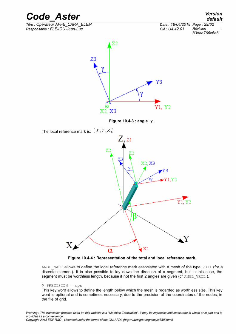
[Figure 10.4-3]
Figure 10.4-1 : angle .
Figure 10.4-2 : angle .
Note: for the figure 10.4-2, the swing angle is negative.
Warning : The translation process used on this website is a "Machine Translation". It may be imprecise and inaccurate in whole or in part and isprovided as a convenience.Copyright 2018 EDF R&D - Licensed under the terms of the GNU FDL (http://www.gnu.org/copyleft/fdl.html)
Code_Aster Versiondefault
Titre : Opérateur AFFE_CARA_ELEM Date : 18/04/2018 Page : 29/62Responsable : FLÉJOU Jean-Luc Clé : U4.42.01 Révision :
83eae766c6e6
Figure 10.4-3 : angle .
The local reference mark is: X 3Y 3Z 3
Figure 10.4-4 : Representation of the total and local reference mark.
ANGL_NAUT allows to define the local reference mark associated with a mesh of the type POI1 (for adiscrete element). It is also possible to lay down the direction of a segment, but in this case, thesegment must be worthless length, because if not the first 2 angles are given (cf ANGL_VRIL ).
◊ PRECISION = epsThis key word allows to define the length below which the mesh is regarded as worthless size. This keyword is optional and is sometimes necessary, due to the precision of the coordinates of the nodes, inthe file of grid.
Warning : The translation process used on this website is a "Machine Translation". It may be imprecise and inaccurate in whole or in part and isprovided as a convenience.Copyright 2018 EDF R&D - Licensed under the terms of the GNU FDL (http://www.gnu.org/copyleft/fdl.html)

Code_Aster Versiondefault
Titre : Opérateur AFFE_CARA_ELEM Date : 18/04/2018 Page : 30/62Responsable : FLÉJOU Jean-Luc Clé : U4.42.01 Révision :
83eae766c6e6
10.5 Operand CARA = ‘VECT_X_Y’
♦ VALE = ( x1l , x2
l , x3l , y1
d , y2d , y3
d )
x1l , x2
l , x3l
are the 3 components, in the total reference mark, of a vector defining the local axis X 3 .
y1d , y2
d , y3d are the 3 components, in the total reference mark, of a vector Y d , of which projection on
the orthogonal level with X 3 will provide the local axis Y 3 . The local axis Z3 the reference marksupplements then so that the trihedron ( P , X 3 , Y 3 , Z 3 ) that is to say direct [Figure 10.5-1].
Figure 10.5-1 : Definition of VECT_X_Y.
VECT_X_Y allows to define the local reference mark associated with a mesh of the type POI1 or anode (for a discrete element). It is also possible to lay down the direction of a segment, but in thiscase, the segment must be worthless length, because if not the first 2 angles are given (cfANGL_VRIL).
◊ PRECISION =/epsThis key word allows to define the length below which the mesh is regarded as worthless size. This keyword is optional and is sometimes necessary, due to the precision of the coordinates of the nodes, inthe file of grid.
10.6 Operand CARA = ‘ANGL_VRIL’
♦ VALE = In the case of meshs SEG2, the axis x 3 is already carried by the mesh (the direction of x 3 is definedby the classification of two nodes of the mesh, it can be changed by MODI_MAILLAGE/ORIE_LIGNE,[U4.23.04]. It is thus possible to define y 3 and z3 by rotation around x 3 .
is the angle (in degrees) of rotation around x 3 , transforming ( P , x3 , x2 , x2 ) in ( P , x3 , y3 , z3)[Figure 10.4-3].
ANGL_VRIL allows to define the local reference mark around the axis defined by a mesh SEG2 (beamor discrete). 2 angles α and β are defined by the orientation of the segment which must thus benonworthless length.
◊ PRECISION = epsThis key word allows to define the length below which the mesh is regarded as worthless size. This keyword is optional and is sometimes necessary, due to the precision of the coordinates of the nodes, inthe file of grid.
Warning : The translation process used on this website is a "Machine Translation". It may be imprecise and inaccurate in whole or in part and isprovided as a convenience.Copyright 2018 EDF R&D - Licensed under the terms of the GNU FDL (http://www.gnu.org/copyleft/fdl.html)
X3
Yd
Y3

Code_Aster Versiondefault
Titre : Opérateur AFFE_CARA_ELEM Date : 18/04/2018 Page : 31/62Responsable : FLÉJOU Jean-Luc Clé : U4.42.01 Révision :
83eae766c6e6
10.7 Operand CARA = ‘VECT_Y’
♦ VALE = y1d , y2
d , y3d
In the case of meshs SEG2, the axis x 3 is already carried by the mesh (the direction of x 3 is definedby the classification of two nodes of the mesh, it can be changed by MODI_MAILLAGE/ORIE_LIGNE,[U4.23.04]. It is thus possible to define y 3 and z3 by defining a vector.
y1d , y2
d , y3d
are the 3 components of a vector Y d of which projection on the orthogonal level with
x 3 will provide the local axis y 3 [Figure 10.5-1]. The axis z3 is such as ( P , x3 , y3 , z3) that is to
say direct.
VECT_Y allows to define the local reference mark around the axis defined by a mesh SEG2 (beam ordiscrete). 2 angles α and β are defined by the orientation of the segment which must thus benonworthless length.
◊ PRECISION = epsThis key word allows to define the length below which the mesh is regarded as worthless size. This keyword is optional and is sometimes necessary, due to the precision of the coordinates of the nodes, inthe file of grid.
10.8 Operand CARA = ‘GENE_TUYAU’
♦ VALE = ( z1, z2, z3)That NE concern that the elements PIPE (modelings TUYAU_3M or TUYAU_6M).
It is advisable to give the 3 components of a vector z directing the generator of the pipe (continuousline traced on the pipe, defining for each element the origin of the angle used to expressovalization and warping).This vector must be defined in a node or one GROUP_NO end of the pipe. The geometry is then builtautomatically for all the related elements of PIPE.
◊ PRECISION = eps◊ CRITERION = [‘RELATIVE’,‘ABSOLUTE’] [defect]This precision is used for the construction of the generator like defining the limit between a right pipesection and a curved element (distinction based on the alignment of the 3 or 4 nodes of the element).
Warning : The translation process used on this website is a "Machine Translation". It may be imprecise and inaccurate in whole or in part and isprovided as a convenience.Copyright 2018 EDF R&D - Licensed under the terms of the GNU FDL (http://www.gnu.org/copyleft/fdl.html)

Code_Aster Versiondefault
Titre : Opérateur AFFE_CARA_ELEM Date : 18/04/2018 Page : 32/62Responsable : FLÉJOU Jean-Luc Clé : U4.42.01 Révision :
83eae766c6e6
11 Keywords MULTIFIBRE GEOM_FIBRE/
11.1 SyntaxGEOM_FIBRE = gfibre [geom_fibre]
MULTIFIBRE = _F ( ♦ GROUP_MA = lgrma, [l_gr_maille] ♦ GROUP_FIBRE = gfbr, [l_gr_fibre] ◊ PREC_AIRE = precis (0.01), [reality (defect)] ◊ PREC_INERTIE = precise (0.10), [reality (defect)]
Keywords used to define the section of the multifibre beams, (modélisations POU_D_EM orPOU_D_TGM ) while assigning to the element beam (mesh SEG2 ) groups of fibres defined using theoperator DEFI_GEOM_FIBRE (U4-26.01).
11.2 GoalWithin the framework of a modeling of the multifibre type, there are two “levels” of modeling. There ismodeling known as “longitudinal” who will be represented by a beam (geometrical support SEG2) anda modeling planes section (perpendicular to SEG2). The keyword MULTIFIBRE allows to associategroups of fibres (defined beforehand by the operator DEFI_GEOM_FIBRE) with an element beam.GEOM_FIBRE allows to give the name of the concept created by DEFI_GEOM_FIBRE containing thedescription of all the groups of fibres.
Note:For the elements POU_D_EM, it is necessary to affect all the groups of fibres defining the cross-section on only one element beam (see R3.08.08). On the other hand for the elementsPOU_D_TGM, one can affect currently one group of fibre per element beam. If one wants to treatheterogeneous cases of section with elements POU_D_TGM, the operator CREA_MAILLAGEallows to duplicate the support SEG2 so that there is one material by support.
Caution:The contained information in the groups of fibres make it possible to calculate some of theintegrated characteristics of the cross-sections (surface, static and quadratic moments). In spiteof that, for the elements POU_D_TGM, it is necessary to give coherent values for the operands
A , IY , IZ under the keyword BEAM. A checking is carried out on the coherence of these sizes.If the relative error is too important (Confer keywords PREC_AIRE, PREC_INERTIE) a fatal erroris emitted.
11.3 Keyword MULTIFIBRE♦ MULTIFIBRETo define the entities of the grid of beams concerned and the sections which are affected for them.
11.3.1 Operands GROUP_MA
♦ GROUP_MAIttte operand makes it possible to define the entities of the grid of beams (elements SEG2 ) who areconcerned with the occurrence of the keyword factor:
Operands Contents/SignificanceGROUP_MA Assignment with a list of groups of meshs
Warning : The translation process used on this website is a "Machine Translation". It may be imprecise and inaccurate in whole or in part and isprovided as a convenience.Copyright 2018 EDF R&D - Licensed under the terms of the GNU FDL (http://www.gnu.org/copyleft/fdl.html)

Code_Aster Versiondefault
Titre : Opérateur AFFE_CARA_ELEM Date : 18/04/2018 Page : 33/62Responsable : FLÉJOU Jean-Luc Clé : U4.42.01 Révision :
83eae766c6e6
11.3.2 Operand GROUP_FIBRE
♦ GROUP_FIBRE These operands make it possible to define the groups of fibres (among all those defined in theconcept geometry of fibres given by the keyword GEOM_FIBRE ) who are assigned to the elementsbeams of this occurrence of
11.4 Keyword GEOM_FIBRE♦ GEOM_FIBREConcept created by DEFI_GEOM_FIBRE [U4.26.01], containing the description of the whole of thegroups of fibres of the study.
11.5 Operands PREC_AIRE / PREC_INERTIE ◊ PREC_AIRE = precise (0.01), [reality (defect)]◊ PREC_INERTIE = precise (0.10), [reality (defect)]The use of the multifibre beams (POU_D_EM or POU_D_TGM) require to provide extra information,compared to the keywords VALE and CARA, under BEAM.The objective is to check the coherence of information (SURFACE and INERTIA) provided on the onehand by the keyword BEAM and in addition by the key word MULTIFIBRE. The criterion of error isbased on the error relative and is compared either with the value by default or to that given by theuser via the keywords PREC_AIRE and PREC_INERTIE.
If the criterion is not satisfied a fatal error is generated. The relative error is calculated in the followingway:
AIRE POUTRE−( AIRE SECTION+ AIRE FIBRE)
AIRE POUTRE
≤ PREC_AIRE
INERTIE POUTRE−( INERTIESECTION + INERTIE FIBRE)
INERTIE POUTRE
≤ PREC_INERTIE
Note:• SURFACE (FIBRE), SURFACE (SECTION), INERTIA (SECTION), INERTIA (FIBRE)
are calculated starting from the structure of data describing fibres and defined under the keyword GEOM_FIBRE. This structure of data is created by order DEFI_GEOM_FIBRE[U4.26.01].
• SURFACE (FIBRE) is calculated by making the sum of the surfaces of fibres, for all thegroups of fibres defined by the keyword GROUP_FIBRE operand FIBRE orderDEFI_GEOM_FIBRE.
• SURFACE (SECTION) is calculated by making the sum of the surfaces of fibres defined bythe key word GROUP_FIBRE of the operand SECTION order DEFI_GEOM_FIBRE.
• INERTIA (FIBRE) is calculated by making the sum of s.d 2 fibres defined in the whole ofthe groups of fibres defined by the key word GROUP_FIBRE operand FIBRE orderDEFI_GEOM_FIBRE. S: represent the surface of a fibre and D the distance between fibre andthe axis defined by the keyword CARA_AXE_POUTRE operand FIBRE orderDEFI_GEOM_FIBRE.
• INERTIA (SECTION) is calculated by making the sum of the s.d ² elements defined by thekey word GROUP_FIBRE of the operand SECTION order DEFI_GEOM_FIBRE. S: representthe surface of an element and D the distance between the centre of gravity of the elementand the axis defined by the keyword CARA_AXE_POUTRE operand SECTION orderDEFI_GEOM_FIBRE.
Warning : The translation process used on this website is a "Machine Translation". It may be imprecise and inaccurate in whole or in part and isprovided as a convenience.Copyright 2018 EDF R&D - Licensed under the terms of the GNU FDL (http://www.gnu.org/copyleft/fdl.html)

Code_Aster Versiondefault
Titre : Opérateur AFFE_CARA_ELEM Date : 18/04/2018 Page : 34/62Responsable : FLÉJOU Jean-Luc Clé : U4.42.01 Révision :
83eae766c6e6
Note:When the section is defined by a grid (keyword MAILLAGE_SECT under the operand SECTIONorder DEFI_GEOM_FIBRE) the calculation of the total inertia of the whole of the surface elementsdoes not take account of inertia suitable for each element. It is thus necessary to define asufficient number of fibres so that this error is weak and remains lower than PREC_INERTIE.
For example a rectangular section cut out uniformly in the height in n elements leads to thefollowing errors, on the values of inertias.
Cutting 2 3 4 5 6Inertia error 25% 11.11% 6.25% 4.00% 2.77%
Warning : The translation process used on this website is a "Machine Translation". It may be imprecise and inaccurate in whole or in part and isprovided as a convenience.Copyright 2018 EDF R&D - Licensed under the terms of the GNU FDL (http://www.gnu.org/copyleft/fdl.html)

Code_Aster Versiondefault
Titre : Opérateur AFFE_CARA_ELEM Date : 18/04/2018 Page : 35/62Responsable : FLÉJOU Jean-Luc Clé : U4.42.01 Révision :
83eae766c6e6
12 Keyword DISCRETE and DISCRET_2D
12.1 Easily affected characteristics These keywords make it possible to assign directly to entities (meshs or nodes), which supportelements of the type DIS_T, DIS_TR (DISCRETE) or 2D_DIS_T, 2D_DIS_TR (DISCRET_2D),matrices of rigidity, of mass or ofdamping.
On all the entities one can affect matrices corresponding to the degrees of freedom of translation T
only or with the degrees of freedom of translation and rotation TR . The matrices can be diagonalD or full (symmetrical or not symmetrical).
In all the cases (symmetrical, diagonal, complete matrices) the convention of classification of theterms is imposed :• for symmetrical matrices, one will provide only triangular the higher, with a convention imposed
for the classification of the terms (see examples).• for diagonal matrices, one will provide only the terms of the diagonal, with a convention
imposed for the classification of the terms (see examples).• for matrices not-symmetrical, one will provide all the terms, with a convention imposed for the
classification of the terms (see examples).
The matrices can be affected:• with nodes or meshs of the types POI1; they are then known as nodal matrices N ,• with meshs of the type SEG2; they are then known as matrices of connection L .
In the event of assignment of matrices to meshs or nodes, the type of element DISCRETE must beaffected, first, with these meshs or these nodes by the operator AFFE_MODELE [U4.41.01].
12.2 SyntaxDISCRETE and DISCRET_2D = _F ( ♦ GROUP_MA = lgma, [l_gr_maille] ◊ SYME = [‘YES’|‘NOT’] [defect] # matrices of rigidity ♦ / CARA = |‘K_T_D_N’|‘K_TR_D_N’|‘K_T_D_L’|' K_TR_D_L', |‘K_T_N’|‘K_TR_N’|‘K_T_L’|‘K_TR_L’, # matrices of mass / CARA = |‘M_T_D_N’|‘M_TR_D_N’,|‘M_T_D_L’,|‘M_TR_D_L’ |‘M_T_N’|‘M_TR_N’|‘M_T_L’|‘M_TR_L’, # matrices ofdamping / CARA = |‘A_T_D_N’|‘A_TR_D_N’|‘A_T_D_L’|' A_TR_D_L', |‘A_T_N’|‘A_TR_N’|‘A_T_L’|‘A_TR_L’, ♦/VALE = lva, [l_réel] ◊ REFERENCE MARK = [‘LOCAL’, ‘TOTAL’] [defect] ◊ AMOR_HYST = amnh (0.0), [reality (defect)])
Warning : The translation process used on this website is a "Machine Translation". It may be imprecise and inaccurate in whole or in part and isprovided as a convenience.Copyright 2018 EDF R&D - Licensed under the terms of the GNU FDL (http://www.gnu.org/copyleft/fdl.html)

Code_Aster Versiondefault
Titre : Opérateur AFFE_CARA_ELEM Date : 18/04/2018 Page : 36/62Responsable : FLÉJOU Jean-Luc Clé : U4.42.01 Révision :
83eae766c6e6
12.3 Operands 12.3.1 Rules of use
• RIGIDITY or DAMPING and SYME = ‘YES’ (value by default)
CARA CARA ENTITYDIS_*VALE
2D_DIS_*VALE
‘K_T_D_N’ ‘A_T_D_N’ node or POI1 3 terms 2 terms‘K_T_D_L’ ‘A_T_D_L’ SEG2 3 terms 2 terms‘K_TR_D_N’ ‘A_TR_D_N’ node or POI1 6 terms 3 terms‘K_TR_D_L’ ‘A_TR_D_L’ SEG2 6 terms 3 terms‘K_T_N’ ‘A_T_N’ node or POI1 6 terms 3 terms‘K_T_L’ ‘A_T_L’ SEG2 21 terms 10 terms‘K_TR_N’ ‘A_TR_N’ node or POI1 21 terms 6 terms‘K_TR_L’ ‘A_TR_L’ SEG2 78 terms 21 terms
• RIGIDITY or DAMPING and SYME = ‘NOT’
CARA CARA ENTITYDIS_*VALE
2D_DIS_*VALE
‘K_T_N’ ‘A_T_N’ node or POI1 9 terms 4 terms‘K_T_L’ ‘A_T_L’ SEG2 36 terms 16 terms‘K_TR_N’ ‘A_TR_N’ node or POI1 36 terms 9 terms‘K_TR_L’ ‘A_TR_L’ SEG2 144 terms 36 terms
• MASS and SYME = ‘YES’ (value by default)
CARA ENTITYDIS_*VALE
2D_DIS_*VALE
‘M_T_D_N’ node or POI1 1 (mass) 1 (mass)‘M_TR_D_N’ node or POI1 10 (mass/inertia) nonavailable‘M_T_N’ node or POI1 6 (mass/inertia) 3 (mass/inertia)‘M_T_L’ SEG2 21 (mass/inertia) 10 (mass/inertia)‘M_T_D_L’ SEG2 1 (mass/inertia) 1 (mass/inertia)‘M_TR_N’ node or POI1 21 (mass/inertia) 6 (mass/inertia)‘M_TR_D_L’ SEG2 4 (mass/inertia) 4 (mass/inertia)‘M_TR_L’ SEG2 78 (mass/inertia) 21 (mass/inertia)
• MASS and SYME = ‘NOT’
CARA ENTITYDIS_*VALE
2D_DIS_*VALE
‘M_T_N’ node or POI1 9 (mass/inertia) 4 (mass/inertia)‘M_T_L’ SEG2 36 (mass/inertia) 16 (mass/inertia)‘M_TR_N’ node or POI1 36 (mass/inertia) 9 (mass/inertia)‘M_TR_L’ SEG2 144 (mass/inertia) 36 (mass/inertia)
12.3.2 Operands VALE
♦/VALE = lvaOne finds in VALE the list of the values allowing to define the elementary matrix of the discreteelement. The size of this list depends on the type of element.
The keyword is used VALE if effector a standard calculation is wanted. The arguments of this keywordare realities.
Warning : The translation process used on this website is a "Machine Translation". It may be imprecise and inaccurate in whole or in part and isprovided as a convenience.Copyright 2018 EDF R&D - Licensed under the terms of the GNU FDL (http://www.gnu.org/copyleft/fdl.html)

Code_Aster Versiondefault
Titre : Opérateur AFFE_CARA_ELEM Date : 18/04/2018 Page : 37/62Responsable : FLÉJOU Jean-Luc Clé : U4.42.01 Révision :
83eae766c6e6
12.3.3 Operands K_ ( matrices of rigidity) or A_ (matrices of damping)
K_T_D_N / A_T_D_N and SYME = ‘YES’ (value by default)for a mesh of the type POI1 or a node, one finds in correspondence in VALE 3 values k x , k y , k z in
DIS_T and 2 values k x , k y in 2D_DIS_T such as:
K ou A=[k x 0 00 k y 00 0 k z
]U x U y U z
K ou A=[k x 0
0 k y]
U x U y
K_T_D_L / A_T_D_L and SYME = ‘YES’ (value by default)for a mesh of the type SEG2, K being the matrix previously definite:
[ K −K−K K ]Noeud1 Noeud2
it is thus enough to provide the 3 values k x , k y , k z
K_TR_D_N / A_TR_D_N and SYME = ‘YES’ (value by default)for a mesh of the type POI1 or node, one finds in correspondence in VALE 6 values k x , k y , k z ,
k rx , k ry , k rz in DIS_TR or 3 values k x , k y , k rz in 2D_DIS_TR such as:
K ou A=[k x 0 0 0 0 00 k y 0 0 0 00 0 k z 0 0 00 0 0 k rx 0 00 0 0 0 k ry 00 0 0 0 0 k rz
]U x U y U z R x R y R z
K ou A=[
k x 0 00 k y 00 0 k rz
]U x U y R z
K_TR_D_L / A_TR_D_L and SYME = ‘YES’ (value by default)for a mesh of the type SEG2, K being the matrix previously definite:
[ K −K−K K ]Noeud1 Noeud2
it is enough to give the 6 values above.
K_T_N / A_T_N and SYME = ‘YES’ (value by default)for a mesh of the type POI1 or a node, one finds in correspondence in VALE 6 values k1 , k 2 … k6in DIS_T or 3 values k1 , k 2 , k3 in 2D_DIS_T such as:
K ou A=[k1 k 2 k4
k3 k5k6
]U x U y U z
K ou A=[k 1 k2k3 ]
U x U y
Warning : The translation process used on this website is a "Machine Translation". It may be imprecise and inaccurate in whole or in part and isprovided as a convenience.Copyright 2018 EDF R&D - Licensed under the terms of the GNU FDL (http://www.gnu.org/copyleft/fdl.html)

Code_Aster Versiondefault
Titre : Opérateur AFFE_CARA_ELEM Date : 18/04/2018 Page : 38/62Responsable : FLÉJOU Jean-Luc Clé : U4.42.01 Révision :
83eae766c6e6
K_T_N / A_T_N and SYME = ‘NOT’for a mesh of the type POI1 or a node, one finds in correspondence in VALE 9 values k1 , k 2 …
k9 in DIS_T or 4 values k1 , k 2 ,… k 4 in 2D_DIS_T such as:
K ou A=[k 1 k 4 k 7
k 2 k 5 k 8
k 3 k 6 k 9]
U x U y U z
K ou A=[k 1 k 3
k 2 k 4]U x U y
K_T_L / A_T_L and SYME = ‘YES’ (value by default)for a mesh of the type SEG2, one finds in correspondence in VALE 21 values k1 , k 2 … k 21 in
DIS_T or 10 values k1 , k 2 … k10 in 2D_DIS_T and stamps it following rigidity will be affected:
K ou A=[k 1 k 2 k 4 k 7 k11 k 16
k 3 k 5 k 8 k12 k 17
k 6 k 9 k13 k 18
k 10 k14 k 19
k15 k 20
k 21
]U x1 U y1 U z1 U x2 U y2 U z2
K ou A=[k 1 k 2 k 4 k 7
k 3 k 5 k 8
k 6 k 9
k 10]
U x1 U y1 U x2 U y2
K_T_L / A_T_L and SYME = ‘NOT’for a mesh of the type SEG2, one finds in correspondence in VALE 36 values k1 , k 2 … k36 in
DIS_T or 16 values k1 , k 2 … k16 in 2D_DIS_T and stamps it following rigidity will be affected:
K ou A=[K 1 K7 K13 K19 K 25 K31
K 2 K8 K14 K 20 K 26 K32
K 3 K9 K15 K 21 K 27 K33
K 4 K10 K16 K 22 K 28 K34
K 5 K11 K17 K 23 K 29 K35
K 6 K12 K18 K 24 K 30 K36
]U x1 U y1 U z1 U x2 U y2 U z2
K ou A=[k1 k5 k 9 k13k 2 k6 k 10 k14k3 k7 k 11 k15k 4 k8 k 12 k16
]U x1 U y1 U x2 U y2
K_TR_N / A_TR_N and SYME = ‘YES’ (value by default)for a mesh of the type POI1 or a node, one finds in correspondence in VALE 21 values k1 , k 2 …
k 21 in DIS_TR or 6 values k1 , k 2 … k6 in 2D_DIS_TR such as:
K ou A=[k1 k 2 k 4 k 7 k 11 k 16
k 3 k 5 k 8 k 12 k 17
k 6 k 9 k 13 k 18
k 10 k 14 k 19
k 15 k 20
k 21
]U x U y U z Rx R y Rz
K ou A=[k1 k 2 k 4
k 3 k 5
k 6]
U x U y Rz
Warning : The translation process used on this website is a "Machine Translation". It may be imprecise and inaccurate in whole or in part and isprovided as a convenience.Copyright 2018 EDF R&D - Licensed under the terms of the GNU FDL (http://www.gnu.org/copyleft/fdl.html)

Code_Aster Versiondefault
Titre : Opérateur AFFE_CARA_ELEM Date : 18/04/2018 Page : 39/62Responsable : FLÉJOU Jean-Luc Clé : U4.42.01 Révision :
83eae766c6e6
K_TR_N / A_TR_N and SYME = ‘NOT’for a mesh of the type POI1 or a node, one finds in correspondence in VALE 36 values k1 , k 2 …
k36 in DIS_TR or 9 values k1 , k 2 … k9 in 2D_DIS_TR such as:
K ou A=[k 1 k 7 k13 k 19 k 25 k 31
k 2 k 8 k14 k 20 k 26 k 32
k 3 k 9 k15 k 21 k 27 k 33
k 4 k 10 k16 k 22 k 28 k 34
k 5 k 11 k17 k 23 k 29 k 35
k 6 k 12 k18 k 24 k 30 k 36
]U x U y U z Rx R y Rz
K ou A=[k 1 k 4 k 7
k 2 k5 k 8
k 3 k 6 k 9]
U x U y Rz
K_TR_L / A_TR_L and SYME = ‘YES’ (value by default)for a mesh of the type SEG2, one finds in correspondence in VALE 78 values k1 , k 2 … k78 inDIS_TR.
K ou A= [k1 k 2 k 4 k 7 k 11 k16 k 22 k 29 k37 k 46 k 56 k67
k3 k5 k 8 k 12 k17 k 23 k30 k38 k 47 k 57 k68k 6 k 9 k 13 k18 k 24 k31 k39 k 48 k 58 k69
k 10 k 14 k19 k 25 k32 k 40 k 49 k 59 k70k 15 k 20 k 26 k33 k 41 k50 k 60 k71
k 21 k 27 k34 k 42 k51 k 61 k72k 28 k35 k 43 k52 k 62 k73
k36 k 44 k53 k 63 k74k 45 k54 k 64 k75
k55 k 65 k76k 66 k77
k78
]U x1 U y1 U z1 Rx1 R y1 Rz1 U x2 U y2 U z2 Rx2 Ry2 Rz2
or 21 values k1 , k 2 … k 21 in 2D_DIS_TR such as:
K ou A=[k 1 k2 k 4 k7 k11 k16
k3 k 5 k8 k12 k17k 6 k9 k13 k18
k10 k14 k19k15 k20
k21]
U x1 U y1 Rz1 U x2 U y2 Rz2
Warning : The translation process used on this website is a "Machine Translation". It may be imprecise and inaccurate in whole or in part and isprovided as a convenience.Copyright 2018 EDF R&D - Licensed under the terms of the GNU FDL (http://www.gnu.org/copyleft/fdl.html)

Code_Aster Versiondefault
Titre : Opérateur AFFE_CARA_ELEM Date : 18/04/2018 Page : 40/62Responsable : FLÉJOU Jean-Luc Clé : U4.42.01 Révision :
83eae766c6e6
K_TR_L / A_TR_L and SYME = ‘NOT’for a mesh of the type SEG2, one finds in correspondence in VALE 144 values k1 , k 2 … k144 inDIS_TR.
K ou A=[k 1 k13 k 25 k 37 k 49 k 61 k73 k85 k97 k109 k121 k133k 2 k14 k 26 k 38 k 50 k 62 k74 k86 k98 k110 k122 k134k 3 k15 k 27 k 39 k 51 k 63 k75 k87 k99 k111 k123 k135k 4 k16 k 28 k 40 k 52 k 64 k76 k88 k100 k112 k124 k136k 5 k17 k 29 k 41 k 53 k 65 k77 k89 k101 k113 k125 k137k 6 k18 k 30 k 42 k 54 k 66 k78 k90 k102 k114 k126 k138k 7 k19 k 31 k 43 k 55 k 67 k79 k91 k103 k115 k127 k139k 8 k 20 k 32 k 44 k 56 k 68 k80 k92 k104 k116 k128 k140k 9 k 21 k 33 k 45 k 57 k 69 k81 k93 k105 k117 k129 k141k 10 k 22 k 34 k 46 k 58 k 70 k82 k94 k106 k118 k130 k142k 11 k 23 k 35 k 47 k 59 k 71 k83 k95 k107 k119 k131 k143k 12 k 24 k 36 k 48 k 60 k 72 k84 k96 k108 k120 k132 k144
]U x1 U y1 U z1 Rx1 R y1 Rz1 U x2 U y2 U z2 Rx2 Ry2 Rz2
or 36 values k1 , k 2 … k36 in 2D_DIS_TR such as:
K ou A=[k 1 k 7 k13 k19 k25 k31k 2 k8 k14 k20 k26 k32k 3 k 9 k15 k21 k27 k33k 4 k10 k16 k22 k28 k34k 5 k11 k17 k23 k29 k35k 6 k12 k18 k24 k30 k36
]U x1 U y1 R z1 U x2 U y2 R z2
Warning : The translation process used on this website is a "Machine Translation". It may be imprecise and inaccurate in whole or in part and isprovided as a convenience.Copyright 2018 EDF R&D - Licensed under the terms of the GNU FDL (http://www.gnu.org/copyleft/fdl.html)

Code_Aster Versiondefault
Titre : Opérateur AFFE_CARA_ELEM Date : 18/04/2018 Page : 41/62Responsable : FLÉJOU Jean-Luc Clé : U4.42.01 Révision :
83eae766c6e6
12.3.4 Operands M_ Matrices of mass
M_T_D_N and SYME = ‘YES’ (value by default)for a mesh of the type POI1 or a node, one finds in correspondence in VALE 1 value m . The matrixof following mass will be affected:
M =[m 0 00 m 00 0 m]U x U y U z
M_TR_D_N and SYME = ‘YES’ (value by default, nonavailable in 2D_DIS_TR ) for a mesh of the type POI1 or a node, one finds in correspondence in VALE a value of mass m , 6
values of the tensor of inertia (mass): I xx , I yy , I zz , I xy , I yz , I xz and 3 components of the vector of
offsetting of the mass compared to its node: ex ,e y , ez . The matrix of following mass will be affected:
M =[m 0 0 0 m.e z −m.e y
m 0 −m.e z 0 m.e x
m m.e y −m.ex 0V xx V xy V xz
V yy V yz
v zz
]U x U y U z Rx R y R z
V xx= I xx+m (ey2+ez
2)
V yy=I yy+m (ex2+ez
2)
V zz= I zz+m(ex2+e y
2)
V xy= I xy−m e x e y
V yz= I yz−m e y e z
V xz=I xz−m ex e z
Caution:Offsetting must be expressed in the total reference mark: coordinates of the vector NG(offsetting) directed node towards the mass.
M_T_N and SYME = ‘YES’ (value by default)for a mesh of the type POI1 or node, one finds in correspondence in VALE 6 values M 1 , M 2 ,…
M 6 in DIS_T or 3 values M 1 , M 2 , M 3 in 2D_DIS_T and stamps it of following mass will beaffected:
M =[M 1 M 2 M 4
M 3 M 5
M 6]
U x U y U z
M =[M 1 M 2
M 3]
U x U y
See for example the test SDLD27 [V2.01.027].
Warning : The translation process used on this website is a "Machine Translation". It may be imprecise and inaccurate in whole or in part and isprovided as a convenience.Copyright 2018 EDF R&D - Licensed under the terms of the GNU FDL (http://www.gnu.org/copyleft/fdl.html)

Code_Aster Versiondefault
Titre : Opérateur AFFE_CARA_ELEM Date : 18/04/2018 Page : 42/62Responsable : FLÉJOU Jean-Luc Clé : U4.42.01 Révision :
83eae766c6e6
M_T_N and SYME = ‘NOT’for a mesh of the type POI1 or node, one finds in correspondence in VALE 9 values M 1 , M 2 ,…
M 9 in DIS_T or 4 values M 1 , M 2 ,… M 4 in 2D_DIS_T and stamps it of following mass will beaffected:
M =[M 1 M 4 M 7
M 2 M 5 M 8
M 3 M 6 M 9]
U x U y U z
M =[ M 1 M 3
M 2 M 4]
U x U y
M_TR_N and SYME = ‘YES’ (value by default)for a mesh of the type POI1 or node, one finds in correspondence in VALE 21 values M 1 , M 2 ,…
M 21 in DIS_TR or 6 values M 1 , M 2 ,… M 6 in 2D_DIS_TR and stamps it of following mass will
be affected:
M =[M 1 M 2 M 4 M 7 M 11 M 16
M 3 M 5 M 8 M 12 M 17
M 6 M 9 M 13 M 18
M 10 M 14 M 19
M 15 M 20
M 21
]U x U y U z Rx R y Rz
M =[M 1 M 2 M 4
M 3 M 5
M 6]
U x U y Rz
M_TR_N and SYME = ‘NOT’for a mesh of the type POI1 or node, one finds in correspondence in VALE 36 values M 1 , M 2 ,…
M 36 in DIS_TR or 9 values M 1 , M 2 ,… M 9 in 2D_DIS_TR and stamps it of following mass will
be affected:
M =[M 1 M 7 M 13 M 19 M 25 M 31
M 2 M 8 M 14 M 20 M 26 M 32
M 3 M 9 M 15 M 21 M 27 M 33
M 4 M 10 M 16 M 22 M 28 M 34
M 5 M 11 M 17 M 23 M 29 M 35
M 6 M 12 M 18 M 24 M 30 M 36
]U x U y U z Rx Ry Rz
M =[M 1 M 4 M 7
M 2 M 5 M 8
M 3 M 6 M 9]
U x U y Rz
Warning : The translation process used on this website is a "Machine Translation". It may be imprecise and inaccurate in whole or in part and isprovided as a convenience.Copyright 2018 EDF R&D - Licensed under the terms of the GNU FDL (http://www.gnu.org/copyleft/fdl.html)

Code_Aster Versiondefault
Titre : Opérateur AFFE_CARA_ELEM Date : 18/04/2018 Page : 43/62Responsable : FLÉJOU Jean-Luc Clé : U4.42.01 Révision :
83eae766c6e6
M_T_L and SYME = ‘YES’ (value by default)for a mesh of the type SEG2, one finds in correspondence in VALE 21 values M 1 , M 2 ,… M 21 in
DIS_T or 10 values M 1 , M 2 ,… M 10 in 2D_DIS_T and stamps it of following mass will beaffected:
M =[M 1 M 2 M 4 M 7 M 11 M 16
M 3 M 5 M 8 M 12 M 17
M 6 M 9 M 13 M 18
M 10 M 14 M 19
M 15 M 20
M 21
]U x1 U y1 U z1 U x2 U y2 U z2
M =[
M 1 M 2 M 4 M 7
M 3 M 5 M 8
M 6 M 9
M 10]
U x1 U y1 U x2 U y2
M_T_D_L and SYME = ‘YES’ (value by default)for a mesh of the type SEG2, one finds in correspondence in VALE 1 value, in DIS_T and in2_DIS_T, the matrix of following mass will be affected:
M = [ MM ]
Noeud1 Noeud2
the matrix M the same definition has as that given for M_T_D_N.
M_T_L and SYME = ‘NOT’for a mesh of the type SEG2, one finds in correspondence in VALE 36 values M 1 , M 2 ,… M 36 in
DIS_T or 16 values M 1 , M 2 ,… M 16 in 2D_DIS_T and stamps it of following mass will beaffected:
M =[M 1 M 7 M 13 M 19 M 25 M 31
M 2 M 8 M 14 M 20 M 26 M 32
M 3 M 9 M 15 M 21 M 27 M 33
M 4 M 10 M 16 M 22 M 28 M 34
M 5 M 11 M 17 M 23 M 29 M 35
M 6 M 12 M 18 M 24 M 30 M 36
]U x1 U y1 U z1 U x2 U y2 U z2
M =[
M 1 M 5 M 9 M 13
M 2 M 6 M 10 M 14
M 3 M 7 M 11 M 15
M 4 M 8 M 12 M 16]
U x1 U y1 U x2 U y2
Warning : The translation process used on this website is a "Machine Translation". It may be imprecise and inaccurate in whole or in part and isprovided as a convenience.Copyright 2018 EDF R&D - Licensed under the terms of the GNU FDL (http://www.gnu.org/copyleft/fdl.html)

Code_Aster Versiondefault
Titre : Opérateur AFFE_CARA_ELEM Date : 18/04/2018 Page : 44/62Responsable : FLÉJOU Jean-Luc Clé : U4.42.01 Révision :
83eae766c6e6
M_TR_L and SYME = ‘YES’ (value by default)for a mesh of the type SEG2, one finds in correspondence in VALE 78 values M 1 , M 2 ,… M 78 inDIS_TR and stamps it of following mass will be affected:
M =[M 1 M 2 M 4 M 7 M 11 M 16 M 22 M 29 M 37 M 46 M 56 M 67
M 3 M 5 M 8 M 12 M 17 M 23 M 30 M 38 M 47 M 57 M 68
M 6 M 9 M 13 M 18 M 24 M 31 M 39 M 48 M 58 M 69
M 10 M 14 M 19 M 25 M 32 M 40 M 49 M 59 M 70
M 15 M 20 M 26 M 33 M 41 M 50 M 60 M 71
M 21 M 27 M 34 M 42 M 51 M 61 M 72
M 28 M 35 M 43 M 52 M 62 M 73
M 36 M 44 M 53 M 63 M 74
M 45 M 54 M 64 M 75
M 55 M 65 M 76
M 66 M 77
M 78
]U x1 U y1 U z1 Rx1 R y1 Rz1 U x2 U y2 U z2 Rx2 R y2 Rz2
or 21 values M 1 , M 2 ,… M 21 in 2D_DIS_TR
M =[M 1 M 2 M 4 M 7 M 11 M 16
M 3 M 5 M 8 M 12 M 17
M 6 M 9 M 13 M 18
M 10 M 14 M 19
M 15 M 20
M 21
]U x1 U y1 Rz1 U x2 U y2 Rz2
Warning : The translation process used on this website is a "Machine Translation". It may be imprecise and inaccurate in whole or in part and isprovided as a convenience.Copyright 2018 EDF R&D - Licensed under the terms of the GNU FDL (http://www.gnu.org/copyleft/fdl.html)

Code_Aster Versiondefault
Titre : Opérateur AFFE_CARA_ELEM Date : 18/04/2018 Page : 45/62Responsable : FLÉJOU Jean-Luc Clé : U4.42.01 Révision :
83eae766c6e6
M_TR_D_L and SYME = ‘YES’ (value by default)for a mesh of the type SEG2, one finds in correspondence in VALE 4 values M1 , M2 ,… M4 inDIS_TR and stamps it of following mass will be affected:
M =[M 1
M 1
M 1
M 2
M 3
M 4
M 1
M 1
M 1
M 2
M 3
M 4
]U x1 U y1 U z1 Rx1 Ry1 Rz1 U x2 U y2 U z2 Rx2 Ry2 Rz2
or 2 values M1 , M2 in 2D_DIS_TR
M =[M 1
M 1
M 2
M 1
M 1
M 2
]U x1 U y1 R z1 U x2 U y2 R z2
Warning : The translation process used on this website is a "Machine Translation". It may be imprecise and inaccurate in whole or in part and isprovided as a convenience.Copyright 2018 EDF R&D - Licensed under the terms of the GNU FDL (http://www.gnu.org/copyleft/fdl.html)

Code_Aster Versiondefault
Titre : Opérateur AFFE_CARA_ELEM Date : 18/04/2018 Page : 46/62Responsable : FLÉJOU Jean-Luc Clé : U4.42.01 Révision :
83eae766c6e6
M_TR_L and SYME = ‘NOT’for a mesh of the type SEG2, one finds in correspondence in VALE 144 values M 1 , M 2 ,… M 144
in DIS_TR and stamps it of following mass will be affected:
M =[M 1 M 13 M 25 M 37 M 49 M 61 M 73 M 85 M 97 M 109 M 121 M 133
M 2 M 14 M 26 M 38 M 50 M 62 M 74 M 86 M 98 M 110 M 122 M 134
M 3 M 15 M 27 M 39 M 51 M 63 M 75 M 87 M 99 M 111 M 123 M 135
M 4 M 16 M 28 M 40 M 52 M 64 M 76 M 88 M 100 M 112 M 124 M 136
M 5 M 17 M 29 M 41 M 53 M 65 M 77 M 89 M 101 M 113 M 125 M 137
M 6 M 18 M 30 M 42 M 54 M 66 M 78 M 90 M 102 M 114 M 126 M 138
M 7 M 19 M 31 M 43 M 55 M 67 M 79 M 91 M 103 M 115 M 127 M 139
M 8 M 20 M 32 M 44 M 56 M 68 M 80 M 92 M 104 M 116 M 128 M 140
M 9 M 21 M 33 M 45 M 57 M 69 M 81 M 93 M 105 M 117 M 129 M 141
M 10 M 22 M 34 M 46 M 58 M 70 M 82 M 94 M 106 M 118 M 130 M 142
M 11 M 23 M 35 M 47 M 59 M 71 M 83 M 95 M 107 M 119 M 131 M 143
M 12 M 24 M 36 M 48 M 60 M 72 M 84 M 96 M 108 M 120 M 132 M 144
]U x1 U y1 U z1 Rx1 R y1 R z1 U x2 U y2 U z2 R x2 R y2 R z2
or 36 values M 1 , M 2 ,… M 36 in 2D_DIS_TR
M =[M 1 M 7 M 13 M 19 M 25 M 31
M 2 M 8 M 14 M 20 M 26 M 32
M 3 M 9 M 15 M 21 M 27 M 33
M 4 M 10 M 16 M 22 M 28 M 34
M 5 M 11 M 17 M 23 M 29 M 35
M 6 M 12 M 18 M 24 M 30 M 36
]U x1 U y1 Rz1 U x2 U y2 Rz2
Note:Options M_T_L, M_TR_L, M_T_D_L, M_TR_D_L do not correspond in general to an option ofmodeling having a mechanical meaning. They are available to import DhasNS Code_Aster Dbematrices of masses discretized on a mesh of the type SEG2 determined prear another software.Indeed, one affects usually values of specific mass and inertia (mesh POI1 ) by M_T_D_N orM_TR_D_N.
12.3.5 Operand AMOR_HYST
◊ AMOR_HYST = amorhAllows to assign to a discrete element a coefficient to build a matrix of rigidity complexes (hystereticmodeling of damping) the built matrix is:
1 j.amor h . K
where K is the matrix K_* whose values are provided in the same occurrence of the keywordDISCRETE. The matrix of rigidity complexes will be actually built at the time of a call toCALC_MATR_ELEM [U4.61.01] with the option AMOR_HYST (see test SDLD313) and [R5.05.04].
Warning : The translation process used on this website is a "Machine Translation". It may be imprecise and inaccurate in whole or in part and isprovided as a convenience.Copyright 2018 EDF R&D - Licensed under the terms of the GNU FDL (http://www.gnu.org/copyleft/fdl.html)

Code_Aster Versiondefault
Titre : Opérateur AFFE_CARA_ELEM Date : 18/04/2018 Page : 47/62Responsable : FLÉJOU Jean-Luc Clé : U4.42.01 Révision :
83eae766c6e6
12.3.6 Operand REFERENCE MARK
◊ REFERENCE MARK =/‘LOCAL’, / ‘TOTAL’,By defaults the values of the matrices provided for the discrete elements are used to express thecorresponding quantities in REFERENCE MARK = ‘TOTAL’.
If one wishes to define a particular reference mark in a node (or nets of type POI1) one will specifyREFERENCE MARK = ‘LOCAL’ by defining this reference mark by the keyword ORIENTATION [§10].
For a matrix defined on a mesh of the type SEG2 the operand REFERENCE MARK = ‘LOCAL’ allowsto refer to the local reference mark attached to the mesh (initial node, final node) supplemented ifnecessary of an angle of gimlet defined by the keyword ORIENTATION [§10].
Warning : The translation process used on this website is a "Machine Translation". It may be imprecise and inaccurate in whole or in part and isprovided as a convenience.Copyright 2018 EDF R&D - Licensed under the terms of the GNU FDL (http://www.gnu.org/copyleft/fdl.html)

Code_Aster Versiondefault
Titre : Opérateur AFFE_CARA_ELEM Date : 18/04/2018 Page : 48/62Responsable : FLÉJOU Jean-Luc Clé : U4.42.01 Révision :
83eae766c6e6
13 Keyword SOLID MASS
13.1 Easily affected characteristicsAllows to assign to elements 3D or 2D local axes (which can be for example used to define directionsof orthotropism (cf. DEFI_MATERIAU [U4.43.01], DEFI_COMPOR [U4.43.06]. These local axesare defined by the keywords:• ANGL_REP (3 nautical angles) or (ANGL_AXE and ORIG_AXE) or ANGL_EULER (3 angles) in 3D.• ANGL_REP (1 only angle) in 2D.
13.2 SyntaxSOLID MASS = _F ( ♦ GROUP_MA = lgma, [l_gr_maille] ♦/ANGL_REP = ( α , β , γ ), [l_réel] / ANGL_EULER = ( Ψ , θ , φ ), [l_réel] / ♦ ANGL_AXE = ( α , β ), [l_réel] ♦ ORIG_AXE = (x1, x2, x3), [l_réel])
13.3 Operand ANGL_REP
α , β , γ are the 3 nautical angles (as for the keyword ORIENTATION, cf [§10]) defining the local
axes (x , y , z ) , which corresponds to the reference mark of orthotropism (L , T , N ) . In 2D, it isnecessary to only give α what defines the reference mark (LT) in the plan.
13.4 Operand ANGL_EULER Definition of the 3 angles of Euler which make it possible to direct the local reference mark with theelement. The passage of the fixed reference frame O X Y Z with the reference frame related to the
solid O x3 y3 z3 is made by three successive rotations:
The precession Ψ , around the axis O Z ,makes pass from O X Y Z with the referenceframe O x1 y1 z 1 .
Nutation θ , around the axis O x1 , makespass from O x1 y1 z 1 with O x 2 y 2 z 2 .
Clean rotation φ , around the axis O z 2 ,makes pass from O x 2 y 2 z 2 with the referenceframe related to the solid O x3 y 3 z3 .
Warning : The translation process used on this website is a "Machine Translation". It may be imprecise and inaccurate in whole or in part and isprovided as a convenience.Copyright 2018 EDF R&D - Licensed under the terms of the GNU FDL (http://www.gnu.org/copyleft/fdl.html)

Code_Aster Versiondefault
Titre : Opérateur AFFE_CARA_ELEM Date : 18/04/2018 Page : 49/62Responsable : FLÉJOU Jean-Luc Clé : U4.42.01 Révision :
83eae766c6e6
13.5 Operands ANGL_AXE/ORIG_AXE These keywords are to be given in 3D only to define local axes for which one will use a property ofsymmetry of revolution, or of transverse isotropy (for example: structure with orthotropic cylindricalsymmetry).ANGL_AXE = ( , ) the axis of revolution defines x1 , , being the first two nauticalangles,ORIG_AXE = (x1, x2, x3) a point defines O1 axis.
13.6 Example of useOne seeks to model a cylinder made up of a material rubber band isotropic transverse of typeELAS_ISTR, so that the axis of orthotropism of material is in the direction of the cylinder. Thecharacteristics of such a material are to be defined in the local reference marks of the elements, withconvention that the axis of orthotropism must be carried by N (cf. DEFI_MATERIAU [U4.43.01][§3.5]).
O N can imagine two case: • the axis of the cylinder was defined according to Z in the total reference mark. In this case,
without carrying out of rotation of the local reference marks, there are by default( X , Y , Z )=(L , T , N ) and N // Z as it is wished;
• the axis of the cylinder was defined according to Y in the total reference mark. It is thennecessary to carry out a rotation of the local reference marks to bring N according to Y asit is wished . One uses AFFE_CARA_ELEM (MASSIF=_F (ANGLE_REP = (0. , 0. , -
90.),),) what produces the transformation (L , T , N )=( X ,−Z , Y ) , and one has
then well N // Y .
Warning : The translation process used on this website is a "Machine Translation". It may be imprecise and inaccurate in whole or in part and isprovided as a convenience.Copyright 2018 EDF R&D - Licensed under the terms of the GNU FDL (http://www.gnu.org/copyleft/fdl.html)

Code_Aster Versiondefault
Titre : Opérateur AFFE_CARA_ELEM Date : 18/04/2018 Page : 50/62Responsable : FLÉJOU Jean-Luc Clé : U4.42.01 Révision :
83eae766c6e6
14 Keyword POUTRE_FLUI
14.1 SyntaxPOUTRE_FLUI = _F ( ♦ GROUP_MA = lgma, [l_gr_maille] ♦ B_T = BT, [reality] ♦ B_N = bn, [reality] ♦ B_TN = btn, [reality] ♦ A_FLUI = aflui, [reality] ♦ A_CELL = acell, [reality] ♦ COEF_ECHELLE = ech, [reality])
14.2 Easily affected characteristicsThis keyword factor makes it possible to define the characteristics of the finite elements (hexahedronwith 8 or 20 nodes) associated with modeling ‘3D_FAISCEAU’, cf the order AFFE_MODELE[U4.41.01]. This modeling relates to the representation of a periodic network of tubes bathed by anincompressible fluid [R4.07.05]. An example is given in the test SDLV111 [V2.04.111].
14.3 Operand GROUP_MA Place of employment of the elementary characteristics:• list of groups of meshs (keyword GROUP_MA).
14.4 Operands A_FLUI / A_CELL / COEF_ECHELLEThe periodic cell of the medium to be homogenized is two-dimensional.The basic periodic cell which is used to calculate thehomogenized coefficients is obtained by homothety startingfrom the real periodic cell of the medium.
♦ A_FLUI: Surface of the part occupied by the fluid in the basic periodic cell
♦ A_CELL : Surface of the basic periodic cell
♦ COEF_ECHELLE: Coefficient of homothety allowing to transform the real periodic cell into the basicperiodic cell
14.5 Operands B_T / B_N / B_TN
Homogenized coefficients of the problem fluid-structure calculated in the reference mark T , N [R4.07.05].The orientation of this reference mark is fixed by the keyword factor ORIENTATION. Direction L isinevitably parallel to the beam axis of tubes.
Warning : The translation process used on this website is a "Machine Translation". It may be imprecise and inaccurate in whole or in part and isprovided as a convenience.Copyright 2018 EDF R&D - Licensed under the terms of the GNU FDL (http://www.gnu.org/copyleft/fdl.html)

Code_Aster Versiondefault
Titre : Opérateur AFFE_CARA_ELEM Date : 18/04/2018 Page : 51/62Responsable : FLÉJOU Jean-Luc Clé : U4.42.01 Révision :
83eae766c6e6
15 Keyword GRID
15.1 SyntaxGRID = _F ( ♦ GROUP_MA = lgma, [l_gr_maille] ♦/SECTION = S1, [reality] / SECTION_FO = S1fct [function] ♦/ANGL_REP_1 = ( α , β ) [l_réel] / ANGL_REP_2 = ( α , β ) [l_réel] / VECT_1 = (vx, vy, vz) [l_réel] / VECT_2 = (vx, vy, vz) [l_réel] ◊/OFFSETTING = ez, [reality] / EXCENTREMENT_FO = ezfct [function] ◊ COEF_RIGI_DRZ = kz (1.E-10), [reality (defect)])
15.2 Easily affected characteristics
Figure 15.2-1 : replacement of the reinforcements by an equivalent tablecloth
Allows to define characteristics of a tablecloth characterized by a rigidity in only one direction, used inparticular to model tablecloths of reinforcements in the reinforced concrete hulls, (see for example thetest SSNS100 [V6.05.100]), affected with modelings GRILLE_EXCENTRE or GRILLE_MEMBRANE.To describe a “lattice” of reinforcements, it is enough to superimpose two elementsGRILLE_EXCENTRE or GRILLE_MEMBRANE whose orientations (and thus rigidities) are orthogonal(see example in the following paragraph).
15.3 Description of the operandsThe following geometrical data are necessary to model the tablecloth of reinforcements:
♦/SECTION = S1
/ SECTION_F0 = S1fct SECTION : section of the reinforcements in direction 1, by unit of length. It thus corresponds to the
section cumulated over a width unit. If there is a section s all them 1/5ème of unit, the cumulatedsection is 5×s .SECTION_FO : function giving the section of the reinforcements in direction 1, by unit of length. It thuscorresponds to the section cumulated over a width unit. This function depends on the geometry( X , Y , Z ) and is evaluated in the centre of gravity of the mesh.
Warning : The translation process used on this website is a "Machine Translation". It may be imprecise and inaccurate in whole or in part and isprovided as a convenience.Copyright 2018 EDF R&D - Licensed under the terms of the GNU FDL (http://www.gnu.org/copyleft/fdl.html)

Code_Aster Versiondefault
Titre : Opérateur AFFE_CARA_ELEM Date : 18/04/2018 Page : 52/62Responsable : FLÉJOU Jean-Luc Clé : U4.42.01 Révision :
83eae766c6e6
◊/OFFSETTING = ez
/ EXCENTREMENT_F0 = ezfct OFFSETTING : value of offsetting e z (constant for all the nodes of the mesh) of the tablecloth ofreinforcements compared to the mesh support (distance measured on the normal of the meshsupport), (modeling GRILLE_EXCENTRE only).EXCENTREMENT_F0 : function which gives the offsetting (constant for all the nodes of the mesh) of thetablecloth of reinforcements compared to the mesh support (distance measured on the normal of themesh support), (modeling GRILLE_EXCENTRE only). This function depends on geometry (X, Y, Z) andis evaluated in the centre of gravity of the mesh.
◊ COEF_RIGI_DRZ = to see keyword HULL [§8].
♦/ANGL_REP_1 = to see ANGL_REP keyword HULL [§8].
This keyword makes it possible to define the reference axis x local reference mark starting from twonautical angles. It defines also the reference mark in which the deformations are calculated,constraints, curves, etc.
/ ANGL_REP_2 = to see ANGL_REP keyword HULL [§8].
This keyword makes it possible to define the reference axis y local reference mark starting from twonautical angles. It defines also the reference mark in which the deformations are calculated,constraints, curves, etc.
/ VECT_1 = (vx, vy, vz) CE keyword allows also to fix the local reference mark of the element. The projection of the vectorindicated via the keyword VECT_1 the vector defines x room.
/ VECT_2 = (vx, vy, vz)CE keyword allows also to fix the local reference mark of the element. The projection of the vectorindicated via the keyword VECT_2 the vector defines y room. For example, in the case of acylindrical geometry, it makes it possible to define the directions of the reinforcementscircumferentialS.
To define a grid containing of the reinforcements in the longitudinal direction and the transversedirection, it is necessary to create two layers of elements (order CREA_MAILLAGE, keywordCREA_GROUP_MA), a layer of element for the longitudinal direction and a second layer of elements forthe transverse direction:
GRILLE= ( _F (GROUP_MA = ‘GEOL’, SECTION = 0.02, ANGL_REP_1 = (0.0, 0.0,), OFFSETTING = 0.0, ), _F (GROUP_MA = ‘GEOT’, SECTION = 0.01, ANGL_REP_1 = (90.0, 0.0,), OFFSETTING = 0.01, ),)
Warning : The translation process used on this website is a "Machine Translation". It may be imprecise and inaccurate in whole or in part and isprovided as a convenience.Copyright 2018 EDF R&D - Licensed under the terms of the GNU FDL (http://www.gnu.org/copyleft/fdl.html)

Code_Aster Versiondefault
Titre : Opérateur AFFE_CARA_ELEM Date : 18/04/2018 Page : 53/62Responsable : FLÉJOU Jean-Luc Clé : U4.42.01 Révision :
83eae766c6e6
16 Keyword MEMBRANE
16.1 SyntaxMEMBRANE= _F ( ♦ GROUP_MA = lgma, [l_gr_maille] ♦ / THICK = ep [reality] ♦ / ANGL_REP_1 = ( α , β ) [l_R]
/ ANGL_REP_2 = ( α , β ) [l_R] / VECT_1 = (vx, vy, vz) [l_R] / VECT_2 = (vx, vy, vz) [l_R] ◊/N_INIT =/ ninit [reality] / 0. [defect])
16.2 Easily affected characteristicsOne distinguishes two behavior for the membrane. ON has of a linear behavior for the smalldeformations and a nonlinear behavior for the great deformations.
For the linear behavior:
Figure 16.2-1: replacement of the reinforcements by a membrane
The keyword MEMBRANE allows to define characteristics of an anisotropic tablecloth when modelingMEMBRANE, is used (see for example the test SSLS138 [V3.03.138]). It can in particular be used tomodel elastic tablecloths of reinforcements in the reinforced concrete hulls. This modeling can beassociated with elements with interface to model the decoherence of this tablecloth. The rigidity of thismembrane is indicated under DEFI_MATERIAU/ELAS_MEMBRANE, cf. [U4.43.01].
For the nonlinear behavior:
The keyword MEMBRANE allows to define characteristics of an isotropic membrane when modelingMEMBRANE, is used (see for example the test SSNS115A [V6.05.115]). The rigidity and thePoisson's ratio of this membrane are indicated under DEFI_MATERIAU/ELAS and the law of behaviorunder STAT_NON_LINE/RELATION/ELAS_MEMBRANE_SV or ELAS_MEMBRANE_NH [U4.51.11].One has only two laws of behaviors very-rubber bands: the law of Coming Saint – Kirchhoff and thelaw Néo-Hookéenne.
Warning : The translation process used on this website is a "Machine Translation". It may be imprecise and inaccurate in whole or in part and isprovided as a convenience.Copyright 2018 EDF R&D - Licensed under the terms of the GNU FDL (http://www.gnu.org/copyleft/fdl.html)

Code_Aster Versiondefault
Titre : Opérateur AFFE_CARA_ELEM Date : 18/04/2018 Page : 54/62Responsable : FLÉJOU Jean-Luc Clé : U4.42.01 Révision :
83eae766c6e6
16.3 Description of the operands
THICK ♦/ = epTHICK represent the thickness of the membrane who must be expressed in the same units as thecoordinates of the nodes of the grid. This thickness is not taken into account in small deformations andthus affects only with one nonlinear behavior.
♦/ANGL_REP_1 = to see ANGL_REP keyword HULL [§8].With a linear behavior, this keyword defines the local reference mark related to the anisotropicbehavior of the membrane, in which the strains and the stresses are calculated. It makes it possible todefine the reference axis x local reference mark starting from two nautical angles. If one placesoneself into nonlinear, as the membrane cannot have that an isotropic behavior the keyword will onlybe used to modify the reference mark of posting of the constraints.
/ ANGL_REP_2 = to see ANGL_REP keyword HULL [§8].Operation identical to ANGL_REP_1 but it makes it possible to define the reference axis y localreference mark starting from two nautical angles.
/ VECT_1 = (vx, vy, vz)Just like ANGL_REP_1 and ANGL_REP_2, this keyword makes it possible to fix the local referencemark of the element. The projection of the vector indicated via the keyword VECT_1 the vector definesx room.
/ VECT_2 = (vx, vy, vz)Just like ANGL_REP_1 and ANGL_REP_2, this keyword makes it possible to fix the local referencemark of the element. The projection of the vector indicated via the keyword VECT_2 the vector definesy room. For example, in the case of a cylindrical geometry, it makes it possible to lay down the
direction of the membranes in manner circonférenTielle.
◊/N_INIT =/ninit [reality] / 0. [defect]
This keyword makes it possible to define an initial pre-tensioning allowing the convergence ofcalculation into nonlinear (it is thus useless into linear). It is applied only to the first step of time. It isexpressed in unit of force per unit of length.
Warning : The translation process used on this website is a "Machine Translation". It may be imprecise and inaccurate in whole or in part and isprovided as a convenience.Copyright 2018 EDF R&D - Licensed under the terms of the GNU FDL (http://www.gnu.org/copyleft/fdl.html)

Code_Aster Versiondefault
Titre : Opérateur AFFE_CARA_ELEM Date : 18/04/2018 Page : 55/62Responsable : FLÉJOU Jean-Luc Clé : U4.42.01 Révision :
83eae766c6e6
17 Keyword RIGI_PARASOL
17.1 SyntaxRIGI_PARASOL = _F ( # Meshs being used to distribute the characteristics of the discrete ones ♦ GROUP_MA = l_gma, [l_group_ma] # Meshs of the type POI1 corresponding to the discrete ones ◊/GROUP_MA_POI1 = gmapoi1, [group_ma] # Meshs of the type SEG2 corresponding to the discrete ones / GROUP_MA_SEG2 = l_gma, [l_group_ma] # Functions of distribution ♦/FONC_GROUP = l_fg, [l_fonction] / COEF_GROUP = l_cg, [l_réel] # total Stiffnesses to distribute ♦ CARA =/. |’K_TR_D_N'|' K_T_D_N'| |' K_TR_D_L'|' K_T_D_L'| / |’A_TR_D_N'|' A_T_D_N'| |' A_TR_D_L'|' A_T_D_L' [l_txm] ♦ VALE = l_val, [l_réel] ◊ REFERENCE MARK = [‘LOCAL’|'TOTAL’], [defect] # Centers revolves ♦ GROUP_NO_CENTRE = gno, [group_no] / COOR_CENTRE = l_xyz, [l_réel] # EuroPlexus ◊ EUROPLEXUS = [’NOT‘|’ OUI'] [defect] # Output unit ◊ UNIT = links, [entirety]),
17.2 Easily affected characteristicsThis functionality corresponds to a methodology used to determine the characteristics of discreteelements (springs of translation and/or rotation) to apply to the nodes of a foundation raft starting fromresults got by the code PARASOL.This option is available in 3D and 2D. In the case 3D the foundation raft will be modelled by a surface,in the case 2D it will be modelled by a line (test SSNL130 [V6.02.130]). In the case 2D the discreteones are ‘2D_DIS_TR’ or ‘2D_DIS_T’.
One must affect modeling ‘DIS_TR’ or ‘DIS_T’ in 3D, on the group of nodes which compose thefoundation raft. The meshs which compose the foundation raft (pertaining to the groups l_gma) carrya modeling of plate (DKT, DST) or a modeling of face of 3D (test SDLS108 [V2.03.108]).
It is necessary to distinguish a group from meshs for the foundation raft, to declare behind thekeyword GROUP_MA keyword factor RIGI_PARASOL, and a group of meshs with 1 node being basedon the nodes of this foundation raft which it is necessary to model and declare in AFFE_MODELE in theform of specific meshs of type POI1. If the meshs are of type POI1, it should be indicated using thekeyword GROUP_MA_POI1 keyword factor RIGI_PARASOL.The use of specific meshs of type POI1 is necessary for the assignment of laws of behavior in theoperators of nonlinear calculation.
Warning : The translation process used on this website is a "Machine Translation". It may be imprecise and inaccurate in whole or in part and isprovided as a convenience.Copyright 2018 EDF R&D - Licensed under the terms of the GNU FDL (http://www.gnu.org/copyleft/fdl.html)

Code_Aster Versiondefault
Titre : Opérateur AFFE_CARA_ELEM Date : 18/04/2018 Page : 56/62Responsable : FLÉJOU Jean-Luc Clé : U4.42.01 Révision :
83eae766c6e6
17.3 Description of the operands♦ GROUP_MA List of the groups of meshs which compose the foundation raft.
◊ GROUP_MA_POI1 List of the groups of points including the nodes of the groups of meshs defined by GROUP_MA. Thatmakes it possible to declare the nodes of a foundation defined by meshs like specific meshs POI1 inorder to affect the characteristics to them RIGI_PARASOL. That makes it possible to affect to themmaterials or behaviors for the use of a nonlinear operator. If it is not present, the nodes are regardedas late meshs for a strictly linear study.
♦ FONC_GROUP / COEF_GROUPList of functions or real coefficients. There are as many arguments in this list than there are groups ofmeshs which compose the foundation raft (definite under the keyword GROUP_MA). The functionsmust have as a X-coordinate the distance to the centre of gravity (keyword defined byGROUP_NO_CENTRE / COOR_CENTRE).
♦ CARA/VALETotal stiffnesses of ground, resulting from the code PARASOL are provided by the user using thekeywords CARA and VALE as for the discrete elements. One can also select the nature of thereference mark (total or local) in which one defines the characteristics of the springs (keywordREFERENCE MARK). Stiffnesses or the depreciation only defined in translation can also be distributed(K_T_D_N or A_T_D_N , pas de stiffness in rotation), in this case it is only necessary to give 3 values
behind VALE=k x , k y , k z .
♦/GROUP_NO_CENTRE = gno / COOR_CENTRE = l_xyzTo define the center of the foundation raft (calculated by the code PARASOL), one can is to give thecoordinates (three realities given behind the keyword COOR_CENTRE), that is to say to give the nameof a group containing one only node of the grid (keyword GROUP_NO_CENTRE).
◊ EUROPLEXUSIf this key word is YES, Code_Aster create a structure of data exploited by the macro orderCALC_EUROPLEXUS. For more detail to see documentation associated with Europlexus and the casetest PLEXU01A who implements this functionality.
◊ UNITIf this key word is present, Code_Aster creates a file, corresponding to the number of unit, whichcontains the stiffnesses of discrete affected with the various nodes.
17.4 Principle of determination of the characteristics of the discreteelementsThe document [R4.05.01] “Seismic answer by transitory analysis” give theoretical information aboutthe method employed.In 3D, the foundation raft is represented by a set of surface elements of centre of gravity O . Usingthe code PARASOL, one obtains 6 total sizes which characterize the coupling between the ground and
the foundation raft: three stiffnesses of translation K x , K y , K z and three stiffnesses of rotationKr x , Kr y , Krz .
In each node of the grid of the foundation raft, Code_Aster seek the characteristics in stiffness of a
discrete element of type K_TR_D_N k x , k y , k z , kr x , kr y , kr z cf [R4.05.01].To determine the stiffnesses of translation, one forces that they are proportional to the surfacerepresented by the node and a function of distribution depending on the distance to the centre of
Warning : The translation process used on this website is a "Machine Translation". It may be imprecise and inaccurate in whole or in part and isprovided as a convenience.Copyright 2018 EDF R&D - Licensed under the terms of the GNU FDL (http://www.gnu.org/copyleft/fdl.html)

Code_Aster Versiondefault
Titre : Opérateur AFFE_CARA_ELEM Date : 18/04/2018 Page : 57/62Responsable : FLÉJOU Jean-Luc Clé : U4.42.01 Révision :
83eae766c6e6
gravity of the foundation raft. That is to say S P the surface attached to the node P and f r the function of distribution where r is the distance from the node P with the node O .For the stiffnesses of rotation, one distributes the remainder in the same way (what remains afterhaving removed the contributions due to the translations) that the translations.
If one calculates the efforts and the moments resulting at the point O had with the distribution of thesprings in each node of the grid of the foundation raft and if one identifies them with the valuesobtained by PARASOL, the following formulas are obtained:
k x= K x/(∑p
S ( p) f (op)) ; k x( p)=k x S ( p) f (op)
k y=K y/(∑p
S ( p) f (op)) ; k y( p )=k y S ( p) f (op)
k z=K z /(∑p
S ( p) f (op)) ; k z( p )=k z S ( p) f (op)
k rx=(K rx−∑p
( k z ( p) yop2 +k y( p ) z op
2 ))/(∑p
S ( p) f (op)) ; k rx( p )=k rx S ( p ) f (op)
k ry=( K ry−∑p
( k x( p) z op2 +k z( p ) xop
2 ))/(∑p
S ( p) f (op)) ; k ry( p )=k ry S ( p ) f (op)
k rz=( K rz−∑p
( k x ( p) y op2 +k y ( p) x op
2 ))/(∑p
S ( p) f (op)) ; k rz( p)=k rz S ( p ) f (op)
If the key word INFORMATION = 2, the computed values above are written in the file MESSAGE withthe format of the orders of Code_Aster.
Notice 1 :Calculation of the area attached to the point P .For each surface mesh of the foundation raft, one calculates surface, one divides it by thenumber of tops of the mesh and one affects this contribution to each node of the mesh. One
ensures then: Sradier=∑p
S p .
Notice 2:It is considered that one can apply the same formulas to carry out a distribution of discreteelements of damping.
17.5 Example of useN°1 example RIGI_PARASOL = _F (GROUP_MA = to erase, COEF_GROUP = 2. , NOEUD_CENTRE =‘P1’, CARA = (‘K_TR_D_N’, ‘A_TR_D_N’), VALE = (6 realities, 6 realities),)
N°2 example: INFORMATION = 2 RIGI_PARASOL=_F (GROUP_MA=' DALLE', COEF_GROUP=1.0, GROUP_NO_CENTRE=' PCDG', GROUP_MA_POI1=' RESSORT', REPERE=' GLOBAL', CARA=' K_T_D_N', VALE= (10000.0, 10000.0, 10000.0,),),
An extract of posting in the output file:PAS DE REPARTITION EN ROTATION POUR DES K_T_D_N _F (NOEUD=' N1 ‘, CARA=’ K_T_D_N', VALE= ( 1.56250E+02, 1.56250E+02, 1.56250E+02,), REPERE=' GLOBAL'), _F (NOEUD=' N2 ‘, CARA=’ K_T_D_N', VALE= ( 1.56250E+02, 1.56250E+02, 1.56250E+02,), REPERE=' GLOBAL'), _F (NOEUD=' N3 ‘, CARA=’ K_T_D_N',
Warning : The translation process used on this website is a "Machine Translation". It may be imprecise and inaccurate in whole or in part and isprovided as a convenience.Copyright 2018 EDF R&D - Licensed under the terms of the GNU FDL (http://www.gnu.org/copyleft/fdl.html)

Code_Aster Versiondefault
Titre : Opérateur AFFE_CARA_ELEM Date : 18/04/2018 Page : 58/62Responsable : FLÉJOU Jean-Luc Clé : U4.42.01 Révision :
83eae766c6e6
VALE= ( 3.12500E+02, 3.12500E+02, 3.12500E+02,), REPERE=' GLOBAL'),
Warning : The translation process used on this website is a "Machine Translation". It may be imprecise and inaccurate in whole or in part and isprovided as a convenience.Copyright 2018 EDF R&D - Licensed under the terms of the GNU FDL (http://www.gnu.org/copyleft/fdl.html)

Code_Aster Versiondefault
Titre : Opérateur AFFE_CARA_ELEM Date : 18/04/2018 Page : 59/62Responsable : FLÉJOU Jean-Luc Clé : U4.42.01 Révision :
83eae766c6e6
18 Keyword RIGI_MISS_3D
18.1 SyntaxRIGI_MISS_3D = _F ( ♦ GROUP_MA_POI1 = l_gma, [l_group_ma] ◊ GROUP_MA_SEG2 = l_gma, [l_group_ma] ♦ FREQ_EXTR = freq, [reality] ◊ UNITE_RESU_IMPE = links (30), [entirety (defect)])
18.2 Easily affected characteristicsThe use of this keyword is dedicated to problems of separation of foundation in order to better takeinto account the carpet of springs of ground than does it RIGI_PARASOL who proportionally distributes6 total stiffnesses under a foundation on the surfaces of the elements surrounding his nodes.
This keyword will affect the exact terms of a matrix of impedance calculated by MISS3D for all thedegrees of freedom of interface (3 times the number of nodes) and for a frequency of extraction given.The assignment of these terms (modeling ‘DIS_T’ ) is done then with the specific meshs POI1nodes of the surface foundation and possibly with the lines of the network of SEG2 superimposed withthe foundation to represent the transverse connections between nodes.
18.3 Description of the operands♦ GROUP_MA_POI1Group of specific meshs of the nodes of the foundation.
◊ GROUP_MA_SEG2Group of meshs of SEG2 connecting the nodes of the foundation transversely.
♦ FREQ_EXTRFrequency of extraction of the matrix of impedance.
◊ UNITE_RESU_IMPELogical unit of the matrix of impedance calculated by CALC_MISS option FILE.
Warning : The translation process used on this website is a "Machine Translation". It may be imprecise and inaccurate in whole or in part and isprovided as a convenience.Copyright 2018 EDF R&D - Licensed under the terms of the GNU FDL (http://www.gnu.org/copyleft/fdl.html)

Code_Aster Versiondefault
Titre : Opérateur AFFE_CARA_ELEM Date : 18/04/2018 Page : 60/62Responsable : FLÉJOU Jean-Luc Clé : U4.42.01 Révision :
83eae766c6e6
19 Keyword MASS_AJOU
19.1 SyntaxMASS_AJOU = _F ( ♦ GROUP_MA = gma, [group_ma] ♦ GROUP_MA_POI1 = gma, [group_ma] ♦ FONC_GROUP = fg, [function])
19.2 Easily affected characteristicsThe objective this keyword is to take into account simply the added mass of fluid in the problems ofstoppings without having to model the fluid as in MACRO_MATR_AJOU and to preserve only thestructure for nonlinear dynamic studies.The idea is thus, in a new option of AFFE_CARA_ELEM, to distribute characteristics of specific mass tothe nodes of the interface fluid-structure of the face upstream without adding degrees of freedom apartfrom the structure.
One is inspired thus by the distribution by total characteristics by rigidity or damping by the optionRIGI_PARASOL of AFFE_CARA_ELEM.
In this new option MASS_AJOU, one distributes with the nodes of the interface fluid-structure withcharacteristics ‘M_T_N' elementary values of directional mass obtained by integration of the normalpressure to each element starting from functions of distribution of this normal pressure depending onthe coordinates - in particular of altitude - in order to express relations of Westergaard for example ormore simply the expression of the hydrostatic pressure.
The assignment of these terms (modeling to declare in AFFE_MODELE : ‘DIS_T’ for a surfaceinterface fluid-structure in 3D and ‘2D_DIS_T’ for a linear interface fluid-structure in 2D) is done thenwith the specific meshs POI1 nodes of the interface fluid-structure using the keywordGROUP_MA_POI1 keyword factor MASS_AJOU.
It is necessary to distinguish these specific meshs from groups of the surface or linear meshs for theinterface fluid-structure, to declare behind the keyword GROUP_MA .
19.3 Description of the operands♦ GROUP_MAGroup of surface meshs (in 3D) or linear (in 2D) of the interface fluid-structure.
♦ GROUP_MA_POI1Group of specific meshs of the nodes of the interface fluid-structure.
♦ FONC_GROUPFunction of distribution of the normal pressure depending on the coordinates of the group of meshscomposing the interface fluid-structure (definite under the keywords GROUP_MA or GROUP_MA_POI1).The function must be homogeneous with a surface density of mass.
Warning : The translation process used on this website is a "Machine Translation". It may be imprecise and inaccurate in whole or in part and isprovided as a convenience.Copyright 2018 EDF R&D - Licensed under the terms of the GNU FDL (http://www.gnu.org/copyleft/fdl.html)

Code_Aster Versiondefault
Titre : Opérateur AFFE_CARA_ELEM Date : 18/04/2018 Page : 61/62Responsable : FLÉJOU Jean-Luc Clé : U4.42.01 Révision :
83eae766c6e6
20 Keyword MASS_REP
20.1 SyntaxMASS_REP = _F ( # Surface or line being used to distribute the mass ♦ GROUP_MA = gr_ma, [group_ma] # Meshs of the type POI1 corresponding to the masses ♦ GROUP_MA_POI1 = gr_poi1, [group_ma] # Masses to distribute on the meshs of GROUP_MA ♦ VALE = mass, [reality] ♦ STANDARD = [‘SURFACE’, ‘LINEAR’, ‘TOTAL’], [txt] # Function of distribution of the mass ◊ FONC_MULT = fonction_mult, [function]),
20.2 Easily affected characteristicsThe objective this keyword is to take into account simply a mass and to distribute it on a surface. Theoption MASS_REP, allows to distribute with the nodes of discrete of characteristic ‘M_T_D_N’ valuesof mass obtained in proportion to the surface of the surface meshs or length of the linear meshs.The assignment (modeling ‘DIS_T’ to declare in AFFE_MODELE ) is done with the specific meshsPOI1 data with GROUP_MA_POI1 . It is necessary to distinguish the specific meshs and the surfacemeshs to declare behind the keyword GROUP_MA.The rule of overload applies [ U1.03.00 ]. If a mesh POI1 is present in several occurrences ofMASS_REP it is the last assignment which is taken into account.In the event of overload information is written in the file of ‘messages’, indicating the numberof overloads carried out.
20.3 Description of the operands♦ GROUP_MASurface groups of meshs.
♦ GROUP_MA_POI1Group of specific meshs, type ‘DIS_T’ to declare in AFFE_MODELE.
♦ VALE = massValue of the mass to be distributed for the surface concerned with GROUP_MA. Its unit is homogeneouswith surface−1 , longueur−1 according to the value of TYPE.
♦ STANDARD = [‘SURFACE’, ‘LINEAR’, ‘TOTAL’]Allows to define the mass to be assigned to the discrete ones of type ‘M_T_D_N’ . This mass isfunction of the surface of the meshs which are connected to the node of the discrete one. One can isto give: • one MASS of ‘SURFACE’ TYPE= : this mass is distributed in proportion to the surface of the
surface meshs connected to the node of the discrete ones. Meshs of the type POI1 are affectedby the mass:
MassePOI1=MasseSurfacique ∗ SurfaceNoeud • one MASS of ‘LINEAR’ TYPE= : this mass is distributed in proportion to the length of the linear
meshs connected to the node of the discrete ones. Meshs of the type POI1 are affected by themass:
MassePOI1=Masse Linéique ∗ Longueur Noeud • one MASS with ‘TOTAL’ TYPE= : it is the total mass to distribute either in proportion to the
surface of the surface meshs or in proportion to the length of the linear meshs, connected to thenode of the discrete ones. Meshs of the type POI1 are affected by the mass:
Warning : The translation process used on this website is a "Machine Translation". It may be imprecise and inaccurate in whole or in part and isprovided as a convenience.Copyright 2018 EDF R&D - Licensed under the terms of the GNU FDL (http://www.gnu.org/copyleft/fdl.html)

Code_Aster Versiondefault
Titre : Opérateur AFFE_CARA_ELEM Date : 18/04/2018 Page : 62/62Responsable : FLÉJOU Jean-Luc Clé : U4.42.01 Révision :
83eae766c6e6
MassePOI1=MasseTotale ∗ SurfaceNoeud
SurfaceTotale
or MassePOI1=MasseTotale ∗ LongueurNoeud
LongueurTotale
◊ FONC_MULT = fonction_multOne can give a function (X, Y, Z) which multiplies the mass to distribute mesh. This function isevaluated in the centre of gravity of the mesh.
Warning : The translation process used on this website is a "Machine Translation". It may be imprecise and inaccurate in whole or in part and isprovided as a convenience.Copyright 2018 EDF R&D - Licensed under the terms of the GNU FDL (http://www.gnu.org/copyleft/fdl.html)