operational telecom network for the connected pipeline … · operational telecom network for the...
TRANSCRIPT

Operational Telecom Network for the Connected Pipeline System Implementation GuideLast Updated: June 30, 2016
Building Architectures to Solve Business Problems

Operational Telecom Network for the Connected Pipeline Systemii
About Cisco Validated Design (CVD) Program
The CVD program consists of systems and solutions designed, tested, and documented to facilitate faster, more reli-
able, and more predictable customer deployments. For more information visit http://www.cisco.com/go/designzone.
ALL DESIGNS, SPECIFICATIONS, STATEMENTS, INFORMATION, AND RECOMMENDATIONS (COLLECTIVELY,
"DESIGNS") IN THIS MANUAL ARE PRESENTED "AS IS," WITH ALL FAULTS. CISCO AND ITS SUPPLIERS DIS-
CLAIM ALL WARRANTIES, INCLUDING, WITHOUT LIMITATION, THE WARRANTY OF MERCHANTABILITY, FIT-
NESS FOR A PARTICULAR PURPOSE AND NONINFRINGEMENT OR ARISING FROM A COURSE OF DEALING,
USAGE, OR TRADE PRACTICE. IN NO EVENT SHALL CISCO OR ITS SUPPLIERS BE LIABLE FOR ANY INDIRECT,
SPECIAL, CONSEQUENTIAL, OR INCIDENTAL DAMAGES, INCLUDING, WITHOUT LIMITATION, LOST PROFITS OR
LOSS OR DAMAGE TO DATA ARISING OUT OF THE USE OR INABILITY TO USE THE DESIGNS, EVEN IF CISCO OR
ITS SUPPLIERS HAVE BEEN ADVISED OF THE POSSIBILITY OF SUCH DAMAGES.
THE DESIGNS ARE SUBJECT TO CHANGE WITHOUT NOTICE. USERS ARE SOLELY RESPONSIBLE FOR THEIR
APPLICATION OF THE DESIGNS. THE DESIGNS DO NOT CONSTITUTE THE TECHNICAL OR OTHER PROFES-
SIONAL ADVICE OF CISCO, ITS SUPPLIERS OR PARTNERS. USERS SHOULD CONSULT THEIR OWN TECHNICAL
ADVISORS BEFORE IMPLEMENTING THE DESIGNS. RESULTS MAY VARY DEPENDING ON FACTORS NOT
TESTED BY CISCO.
The Cisco implementation of TCP header compression is an adaptation of a program developed by the University of California,
Berkeley (UCB) as part of UCB’s public domain version of the UNIX operating system. All rights reserved. Copyright © 1981,
Regents of the University of California.
Cisco and the Cisco logo are trademarks or registered trademarks of Cisco and/or its affiliates in the U.S. and other countries. To
view a list of Cisco trademarks, go to this URL: http://www.cisco.com/go/trademarks. Third-party trademarks mentioned are the
property of their respective owners. The use of the word partner does not imply a partnership relationship between Cisco and any
other company. (1110R).
Any Internet Protocol (IP) addresses and phone numbers used in this document are not intended to be actual addresses and phone
numbers. Any examples, command display output, network topology diagrams, and other figures included in the document are
shown for illustrative purposes only. Any use of actual IP addresses or phone numbers in illustrative content is unintentional and
coincidental.
Operational Telecom Network for the Connected Pipeline System Implementation Guide
© 2016 Cisco Systems, Inc. All rights reserved.

Implementation Guide
C O N T E N T S
Document Objective and Scope v
Contributors vi
C H A P T E R 1 Implementation Overview 1-1
Solution Architecture 1-3
Connected Pipeline Network Overview 1-4
Availability 1-5
Security 1-6
Multiservice Support 1-7
Integrated Management 1-8
Control Center 1-8
C H A P T E R 2 System Testbed 2-1
C H A P T E R 3 System Components and Software Matrix 3-1
Test Components from Cisco 3-1
Test Components from Schneider 3-2
C H A P T E R 4 Connected Pipeline Network Implementation 4-1
Operational Telecom Network Implementation 4-1
Pipeline Station Implementation 4-2
Station Availability 4-3
Controller/RTU Connectivity & Availability 4-3
Dedicated Switch and VLAN 4-4
Layer 2 Redundancy with REP 4-5
Platform Redundancy for Cisco ASR 903 and Cisco ASA 5525-X 4-6
Station Security 4-9
Security for SCADA Traffic - Pipeline and Control Center 4-9
Shutdown Unused Ports 4-9
Trunk Ports 4-9
Port Security 4-9
Infrastructure Management 4-10
Pipeline Telecom Network Implementation 4-11
iiiOperational Telecom Network for the Connected Pipeline System

Contents
Pipeline Telecom Availability 4-11
EoMPLS Pseudowire 4-16
Resilient Ethernet Protocol (REP) 4-17
Pipeline Telecom Security 4-19
MPLS WAN 4-21
MPLS WAN Availability 4-22
MPLS Core Router Platform Redundancy 4-23
Remote Loop-Free Alternate Fast Reroute 4-24
MPLS WAN Segmentation 4-25
Network Management and Time Synchronization 4-27
Network Management 4-27
Cisco Adaptive Security Device Manager 4-27
SNMP and Logging Server 4-28
Out of Band Management 4-28
Time Synchronization 4-29
C H A P T E R 5 Operational Telecom Network: Validation 5-1
Functionality Testing 5-1
High Availability Testing 5-1
Security Testing 5-2
C H A P T E R 6 Operational Telecom Network: Verification 6-1
Functional Verification - Communication between Edge Router in Terminal Station 1 and Control Center 6-1
ASA/Firewall Failover 6-2
A P P E N D I X A Related Documentation A-1
Network Infrastructure A-1
Security A-2
Network Time Protocol A-2
A P P E N D I X B Acronyms and Initialisms B-1
ivOperational Telecom Network for the Connected Pipeline System
Implementation Guide

Preface
This Cisco Operational Telecom Network for the Connected Pipeline System Cisco Validated Design (CVD) documents the best practice design and implementation of safe, highly available, and secure Oil and Gas pipeline infrastructure and applications. It also:
• Describes implementation of the communication network for the Connected Pipeline System and guidance for supporting Supervisory Control and Data Acquisition (SCADA) communication from the Pipeline Network to the Control Center.
• Documents best practices from real world implementations, detailing the designs and architectures that are mapped back to the customer use cases.
• Addresses real-life customer deployment scenarios by providing a solution that supports implementation of a scalable, secure, and redundant operational network supporting both industrial and multiservice applications.
• Details support for implementing redundancy and security for SCADA communication in the Connected Pipeline System.
• Specifies topology for high availability, security services, and network management services implementations.
• Documents suggested equipment and technologies, system level configurations, and recommendations.
• Describes caveats and considerations that pipeline operators should understand as they implement best practices.
Document Objective and ScopeIn this initial release, Cisco has partnered with Schneider Electric to provide architecture, design, and technologies for the Control Centers, Operational Telecoms Network, and the pipeline stations. Cisco provides infrastructure expertise with its unified compute and networking security platforms while Schneider Electric provides the Pipeline Management System (PMS) leadership with its OASyS Dynamic Network of Applications (DNA) SCADA system hardware and software.
This document focuses on the pipeline communications network and security architectures to support pipeline operators. It is recommended that the reader become familiar with the following joint Cisco/Schneider Electric white papers:
• Integrated Enterprise SCADA System Architectures for Safe and Efficient Pipeline Operations at the following URL:
– http://www.cisco.com/c/dam/en/us/solutions/collateral/industry-solutions/dlfe-683318406.pdf
vOperational Telecom Network for the Connected Pipeline System
Implementation Guide

PrefaceContributors
• Converged Telecommunication Architectures for Effective Integrated Pipeline Operations at the following URL:
– http://www.cisco.com/c/dam/en/us/solutions/collateral/industry-solutions/dlfe-683318407.pdf
As with any architecture and design program, functional requirements, use cases, and architectures evolve. Therefore, this CVD will evolve and will be updated in future phases.
Contributors• Kiran Ramaswamy, Senior Software Engineer, IoE Vertical Solutions Group, Cisco Systems, Inc.
• Brandon O'Gorman, Software Engineer, IoE Vertical Solutions Group, Cisco Systems, Inc.
viOperational Telecom Network for the Connected Pipeline System
Implementation Guide

Operational TeImplementation Guide
C H A P T E R 1
Implementation OverviewThis chapter includes the following major topics:
• Solution Architecture, page 1-3
• Connected Pipeline Network Overview, page 1-4
Cisco has designed an Operational Telecom Network architecture to satisfy communication requirements between the Pipeline Network and the Control Center in the Oil and Gas industry. This is in partnership with Schneider Electric and uses their Programmable Logic Controllers (PLCs) in various pipeline stations such as terminal, pump, and block valve stations. These PLCs provide real-time measurements of the pipeline segment such as temperature and pressure. These measurements have to be reliably communicated to the Control Center, which may be located along the pipeline or situated remotely. Schneider's Enterprise Pipeline Management (ePLM) solution helps operators in Control Centers receive real-time data from the pipeline segment. A Pipeline Management System combines operational SCADA with oil and gas industry-specific real-time applications, host-based leak detection, and historical flow measurement.
A well-designed pipeline network architecture provides secure and reliable communication infrastructure. Such an infrastructure uses hardware and software that allows functions to be mobile, scalable, flexible, and robust. The communication infrastructure must provide real-time sharing and collection of pipeline data to the Control Center in safe and efficient manner.
Figure 1-1 provides a brief overview of different stations located along the length of a pipeline segment. Some of these stations include:
• Terminal Stations—Usually mark the start or end of the pipeline segment for a product. Such a terminal station may also house compressor, pump and storage facilities.
• Pump/Boosting Stations—Help in pushing product along the pipeline.
• Block Valve Stations—Provide isolation of the pipeline segment for maintenance.
1-1lecom Network for the Connected Pipeline System

Chapter 1 Implementation Overview
Figure 1-1 Pipeline Overview
Pipeline Management Systems provide pipeline operators the following functions:
• Real-time/near real-time control and supervision of operations along the pipeline through a SCADA system based in one or more Control Centers
• Accurate measurement of flow, volume, and levels to ensure correct product accounting
• Ability to detect and locate pipeline leakage including time, volumes, and location distances
• Integrated security systems for personnel, the environment, and infrastructure using video surveillance, access control, and intrusion detection systems
• Safe operations through instrumentation and safety systems
• Energy management system to visualize, manage and optimize energy consumption within the main stations
The Connected Pipeline System uses Cisco's hardware platforms to connect various stations along the pipeline segment. These stations communicate with the Control Center environment. The Control Center uses Schneider Electric's OASyS SCADA applications for real-time monitoring and control in a data center environment.
This document is the implementation guide for the Operational Telecom Network Solution. The salient features of the architecture are listed below.
• Cisco Aggregation Services Router 903 (Cisco ASR 903) as terminal station edge router for connectivity to wide area MPLS/IP network.
• A pair of Cisco ASA 5525x security appliances providing the redundant firewall capability within the terminal station.
• Cisco Industrial Ethernet 2000 and Cisco Industrial Ethernet 4000 series switches providing connectivity to PLCs in the pipeline station.
3767
51
1-2Operational Telecom Network for the Connected Pipeline System
Implementation Guide

Chapter 1 Implementation Overview Solution Architecture
Solution ArchitectureThe Operational Telecom Network for the Connected Pipeline System uses a hierarchical network design for redundancy, security, and management. The implementation uses dual-supervisor edge routers for connecting the pipeline terminal stations with the wide area network.
• Multiple ring networks between terminal stations using industrial Ethernet switches will ensure failover path for packet.
• A pair of firewall appliances set up in hot/standby mode ensures redundant setup.
• VLANs provide segmentation of pipeline traffic between stations.
• Virtual Routing and Forwarding (VRF) instances ensure segmentation from the terminal station to the Control Center via the Multi-Protocol Label Switching/Internet Protocol (MPLS/IP) network.
The Operational Telecom Network architecture provides an end-to-end solution. Various functions of such an infrastructure are briefly explained below.
• High Availability—Redundancy and reliability mechanisms are built into the Pipeline Network in physical, datalink, and network layers. Industrial Ethernet switches provide access to PLCs within the pipeline station. All these switches are connected to form the Pipeline Network segment. These switches connect to edge routers in the terminal station to terminate the ring architecture. Dual ring architecture provides physical redundancy for the PLCs. Separate switches are deployed for each ring. Appropriate VLANs are configured to ensure segmentation of traffic between multiple pipeline segments. No cross-pollination of traffic exists between the redundant segments. Cisco ASR 903s located in the terminal stations facilitate communication by providing wide-area connectivity to the Control Center using Layer 3 Virtual Private Network (L3VPN). Separate routing and forwarding instances in the router provide segmentation of the traffic from multiple pipeline segments. Redundant supervisors in these routers provide high availability
• Multi-Level Security—Security for the pipeline segments is provided by a pair of Adaptive Security Appliances (ASAs) located in the terminal station. Cisco ASA 5525 platforms configured in hot/standby mode provide redundant firewall capability. This pair of firewalls also acts as the default gateway for all the pipeline segments. All SCADA traffic from the pipeline traverses the firewall before reaching the application servers in the Control Center and vice versa. The access control policy configured on the firewall determines what traffic is allowed between the pipeline and the Control Center. A separate set of Ethernet segments run along the pipeline connecting various stations providing segmentation or isolation. Some of the PLCs in these stations have dual network interface card (NIC) capability and will be connected to two separate switches. These segments create a ring architecture between main stations with intermediate stations forming nodes along the ring. In the pipeline stations, unused ports on the industrial switches are placed in shutdown mode and ports connected to PLCs are configured for port-security.
• Multiservice Support—SCADA traffic from the pipeline segment to the Control Center is usually considered operational traffic. Non-operational traffic is comprised of voice and video communication and physical security such as video surveillance and badge access. Both operational and non-operational traffic may use the same underlying network infrastructure. During congestion, operational traffic will have a higher precedence than non-operational traffic.
• Integrated Management—The pipeline operator needs to have visibility into the performance and health of the network that provides the communications for the pipeline management system. The network management system needs to provide visibility so that the infrastructure alarms, events, and networking statistics are made visible to the operator and acted upon. Devices deployed in the pipeline architecture are managed by common set of network management tools to ensure the status of each device is regularly monitored. These tools can also be used for remote configuration of the devices.
1-3Operational Telecom Network for the Connected Pipeline System
Implementation Guide

Chapter 1 Implementation Overview Connected Pipeline Network Overview
• Open Standards—The network infrastructure is primarily designed for IP traffic. However, the infrastructure is designed with a futuristic approach to support interoperability of current and future applications.
Connected Pipeline Network OverviewThe Operational Telecom Network architecture provides a multiservice environment that encompasses:
• Operational services such as SCADA and process applications
• Non-operational services such as CCTV and voice that enable business efficiency and security along the pipeline
The pipeline requires connectivity for communications between Control Centers, between the Control Centers and the pipeline stations, and for any inter-station communication along the pipeline. Availability, security, multiservice support, integrated management, and open standards are the primary requirements for the network as mentioned in the SCADA system design principles (Figure 1-2).
Figure 1-2 Connected Pipeline Reference Architecture
Every asset along the pipeline requires high availability of communication. Multiple paths through the network are provisioned to support primary and secondary paths to these assets and ensure continuous operations. Services are segmented (physically or logically) and prioritized so that SCADA networks (operational traffic) and multiservice traffic (non-operational traffic) will not affect each other under normal operations, security incidents, or network congestion. Open standards for communication are based on IP, with the ability to transport IP-based SCADA communication protocols, VoIP, and traditional IP-based services, and transparently integrate older serial protocols.
The communications network can be built using various connectivity options (such as Ethernet, MPLS, dense wavelength-division multiplexing [DWDM], cellular, and wireless). Factors that influence the communications architecture include power and space availability at the various sites, physical aspects relating to the environment such as ruggedization, no moving parts, extended temperature ranges, capital and operational costs, and the customer's preferred technology.
L1 Basic
Control
L2 Supervisory
Control
L3 Opera�onal
Control
L3.5 Industrial
DMZ
L4-5 Office & External
Domain
L2.5 Protec�on
IEC62443 ISA99
Horizontal Inter-Zone, Intra-Zone, Inter-System Security
Process Control Power Safety Systems
Compressor / Pump Sta�on
Mul�service
Sta�on WAN, Aggrega�on & Security
Process Domain
Metering / PIG / Terminal Sta�on
Met
erin
g
PIG
Syst
ems
Gas Q
ualit
y
Mul�service Sta�on WAN, Aggrega�on & Security
Process Domain
SCADA & Opera�onal Business Systems
Engineer Worksta�ons
Applica�on Servers
Domain Controller
Instrumenta�on / Sensors Instrumenta�on Instrumenta�on Instrumenta�on
Quantum Quantum
MiCom c264
SIL3 Controller
SIL3 Controller
GTW RI/O GTW RI/O
Historian Operator Sta�on Historian PACIS
Operator Historian Operator Sta�on
Wireless
Mobile Worker
IP Voice
Access Control
CCTV
RFID
Controller Controller Controller
Historian Historian Historian
HMI HMI
SCADA Primary
Leak Detec�on
Physical Security
Operator Worksta�ons
SCADA Backup
Historian Repor�ng
Metering Systems
Main Control Center
Video Opera�ons
Access Opera�ons
Video Storage
Incident Response
Engineering
(virt
uali
-virt
ualiz
ed)
Mul�service Process Domain
Block Valve Sta�on
Quantum
Instrumenta�on
Centralized Opera�ons Office / Business Domain Internet Edge Internet 3rd Party
Support
Voice
Wireless
WLAN Controller
Call Manager
PAGA
Magelis
ION Metering
SEPAM Protec�on
TeSys T Motor Mgt
Al�var Drive
MiCOM Feeder
Protec�on
Magelis
RI/O
ScadaPack
SIL3 Op�on No SIL Op�on
Wireless op�on
Crew Welfare / Infotainment
Decision Support
WAN Networks
Domain Controller
Engineering
Leak Detec�on
Database SCADA
Real-�me
SCADA Historical
Leak Detec�on
Applica�on Test
Real-�me SCADA Zone Development Test
Decision Support
Remote Access
Domain Controllers
(Indu
stria
l DM
Z)
Backup Control Center
Converged Opera�onal Field Telecoms Wireless 3G/LTE, WiMax, 900Mhz RF Mesh, Satellite, Microwave DWDM, Ethernet, IP/MPLS, MPLS-TP
Converged Opera�onal Field Telecoms Wired
Mobile Worker
IP Voice
Access Control
CCTV
RFID
WAN Connec�on & Security WAN Connec�on & Security
Mobile Worker
IP Voice
Access Control
CCTV
RFID
Sta�on WAN, Aggrega�on & Security WAN Connec�on & Security
Phys
ical
Sec
urity
SCAD
A &
Bus
ines
s Sys
tem
s
Voic
e &
PAG
A
Wire
less
Deci
sion
Sup
port
& ID
MZ
3767
52
1-4Operational Telecom Network for the Connected Pipeline System
Implementation Guide

Chapter 1 Implementation Overview Connected Pipeline Network Overview
The Connected Pipeline infrastructure used for validation is comprised of operation telecom and Pipeline Network as shown in Figure 1-3. This architecture is designed to provide high availability, security, multiservice support, integrated management, and open standards for both brown and greenfield deployments. High availability and security are the two prominent requirements that are part of this infrastructure.
Figure 1-3 Operational Telecom Network for Oil and Gas
AvailabilityThe Operational Telecom Network for Connected Pipeline is designed for highly available architecture. Loss of communication will lead to loss of revenue in the industry. The system is designed to provide 24 hours a day and 365 days a year reliable communication between the Control Center and the pipeline segment. No single point of failure will exist in the redundant network. The system is designed to detect any failure and transition to a redundant path/device for seamless SCADA communication between the pipeline segment and the Control Center for monitoring and control.
The Operational Telecom Network infrastructure has the capability for dynamic routing protocols and MPLS and multiple paths exist in the MPLS core network between the Control Center and the pipeline station. Reconvergence mechanisms such as Loop-Free Alternate Fast Reroute (LFA FRR) or Border Gateway Protocol Prefix Independent Convergence (BGP PIC) may be deployed.
• LFA FRR—LFA FRR and Remote LFA FRR (rLFA FRR) are used for unicast MPLS/IP traffic in hub-and-spoke and ring topologies. LFA FRR technologies pre-calculate a backup path for every prefix in the IGP routing table, allowing the node to rapidly switch to the backup path when a failure occurs, providing recovery times on the order of 50 msec or less.
• BGP PIC—For L3VPN services configured in BGP, network re-convergence is accomplished via BGP core and edge PIC throughout the system. This allows for deterministic network re-convergence on the order of 100 msec, regardless of the number of BGP prefixes. BGP FRR
ASR 903 (Dual RP) TS1-RTR1
ASA 5525x TS1-FRW
MPLS Core
ASR 903 CC1-RTR1
Control Center
SCADA A
SCADA B
Terminal Sta�on 1
ASR 903 (Dual RP) TS2-RTR1
ASA 5525x TS2-FRW
SCADA A
Terminal Sta�on 2
SCADA B
WAN-CORE-RTR1
WAN-CORE-RTR2
Pump Sta�on 2 Block Valve Pump Sta�on 1
IE 4000 PS1-ES1
IE 4000 BV1-ES1
IE 4000 PS2-ES1
IE 2000 PS1-ES2
IE 2000 BV1-ES2
IE 2000 PS2-ES2
IE 4000 TS2-ES1
IE 2000 TS2-ES2
IE 2000 TS1-ES2
IE 4000 TS1-ES1
3767
53
1-5Operational Telecom Network for the Connected Pipeline System
Implementation Guide

Chapter 1 Implementation Overview Connected Pipeline Network Overview
technologies pre-calculate a loop free backup path for every prefix in the BGP forwarding table, and rely on the structure and entries in the Label Forwarding Information Base (LFIB) to allow for a fast transition to the alternate paths.
SCADA communication along the pipeline is built on a physically separate redundant ring architecture. These rings terminate at the terminal stations. SCADA_A LAN will be terminating at the terminal station 1 while SCADA_B LAN will be terminating at the terminal station 2. Control Center applications have the ability to communicate with PLCs on either of these LANs. Both the terminal stations are connected to the MPLS core network. The ASR 903 with capability of housing two supervisors is deployed in each terminal station. This setup provides Stateful Switchover (SSO) in case of a supervisor failure. If the entire router on a Control Center application communicating with the pipeline station on SCADA_A LAN has a power loss, the communication between Control Center and pipeline stations automatically switches to the secondary path through the other terminal station using the secondary SCADA_B LAN.
A pair of Cisco ASA 5525s deployed in hot/standby mode in each terminal station provide redundancy capability for the firewall functionality.
Multiple rings are deployed using industrial Ethernet switches along the pipeline to provide redundancy. Resilient Ethernet Protocol (REP) is configured on the ring architecture to ensure loop avoidance along the pipeline segment.
Design of the Operational Telecom Network mandates redundancy at all applicable levels. Refer to Figure 1-2 for redundancy implementation within the framework. The high availability aspect is built into MPLS core, edge-router, firewall, and pipeline network segment with the resources made available for the implementation.
• The MPLS core deployed for fast switching traffic between pipeline segment and the Control Center has the capability to support both operational SCADA traffic and non-operational multiservices traffic like voice and video.
• Cisco ASR 903 with dual supervisor deployed in each terminal station ensures redundancy for a processor failure. These supervisors are configured for SSO and ensure seamless traffic flow in case of a supervisor failure.
• Two security appliances (Cisco ASA 5525x) are deployed in a failover setup to provide redundancy in each of the terminal stations.
• Each station along the pipeline segment has a Cisco Industrial Ethernet 4000 series switch that act as primary path for operational SCADA traffic.
• Each station along the pipeline segment has a Cisco Industrial Ethernet 2000 series switch that act as secondary path for operational SCADA traffic.
• A separate ring of IE switches may be deployed for multiservices traffic.
SecurityThe Operational Telecom Network for Connected Pipeline is designed to provide a secure environment in line with the Purdue Model of Control Hierarchy and International Society of Automation (ISA) standards. Security is deployed to keep the environment safe and operational. The system is designed to prevent unauthenticated access to devices, segregation of operation traffic from other forms of traffic, and end-to-end data integrity.
Firewalls (Cisco ASA 5525x) are deployed at the main stations in the architecture. Within the Purdue Model of Control this is not formally called, but is typically referred to as, a Level 2.5 firewall. It sits between the operational domain of the level 3 and the process control domain levels of 2 and below. Within this architecture, the firewalls provide the following functions:
1-6Operational Telecom Network for the Connected Pipeline System
Implementation Guide

Chapter 1 Implementation Overview Connected Pipeline Network Overview
• Station protection for high availability and inter-zone security (process control, safety system, energy).
• Inter-zone security protecting the SCADA Right to Use (RTU) LANs.
• A policy and security point between pipeline segments. This can be used for inter-pipeline security.
All Layer 3 routing and policy is applied at the main stations. The ASA redundant firewalls positioned in the main stations provide protection of traffic from the WAN and the multiservice network. The block valves only have Layer 2 Ethernet services configured. Segmentation and isolation of the services are provided using VLANs and physical segmentation of each of the services. The firewalls at the main stations will allow SCADA Control Center-to-PLC and vice versa.
Separate VLANs and VRFs ensure that no cross-pollination of SCADA traffic occurs between different pipeline segments. This also ensures operational and multiservice traffic are kept separate throughout from Pipeline Network to Control Center.
REP on Ethernet rings ensures that if all ports are online and operational, a single one of them logically blocks traffic for each VLAN. More on REP operation can be found in the Resilient Ethernet Protocol Overview at the following URL:
• http://www.cisco.com/c/en/us/support/docs/lan-switching/ethernet/116384-technote-rep-00.html#anc3
Security in the Operational Telecom Network is provided in the following methods:
• Separation of pipeline SCADA traffic and multiservices using separate VRF instances in the edge router.
• Separation of SCADA and multiservices traffic in the pipeline segment using separate VLANs: VLAN 100 for primary SCADA network, 103 for secondary SCADA network and VLAN 105 for multiservices.
• Access control policy in firewall allowing access only between the Production zone in the Control Center and the Pipeline Network segments.
• Only necessary ports are permitted in access control. All remaining ports are denied access.
• Port-security on unused ports of the Industrial Ethernet switch.
Multiservice SupportThe infrastructure converges both operational SCADA and non-operational applications providing multiservice-supported architecture. Non-operational applications such as voice, video, and surveillance are segregated physically and logically from the operational SCADA traffic. For physical separation, multiple rings are designed. For logical separation, VLANs and VRFs are configured. One set of Ethernet switches along the pipeline segment is specifically used for SCADA traffic while a separate set of switches is used for non-operational traffic. No cross-pollination of this non-operational traffic will occur with operational SCADA.
A ring topology comprising IE 4000 series of Industrial Ethernet switches are used for VLAN 100 in the pipeline segment (primary SCADA network). To provide redundancy, another ring comprising IE 2000 series of Industrial Ethernet switches are used for VLAN 103 (secondary SCADA network). Both these rings carry operational SCADA traffic. Some of the PLCs have dual Ethernet connection and are able to communicate using primary ring and, in case of failure, transitions to communicate on the secondary ring.
Note The multiservices environment was not implemented as part of the solution.
1-7Operational Telecom Network for the Connected Pipeline System
Implementation Guide

Chapter 1 Implementation Overview Connected Pipeline Network Overview
Integrated ManagementThe network infrastructure for Operational Telecom Network is monitored and managed by variety of Cisco tools. The management ensures compliance with the Fault, Configuration, Accounting, Performance, and Security (FCAPS) model. FCAPS of the network infrastructure is accounted in the integrated management.
Network management tools like logging server, Simple Network Management Protocol (SNMP), and Adaptive Security Device Manager (ASDM) are deployed in the network to manage devices in the Pipeline Network. SSH is deployed on the equipment for secure access. SNMP version 3 is deployed for management. Tools such as Cisco Prime Infrastructure are capable of displaying alerts triggered by various events in the networking equipment.
Control Center The SCADA system monitors pressure, flow, and temperature among other operating data that is communicated back to servers and applications in the Control Center. This data is then displayed to operators and near real-time decisions can be made to help the safe transport of the product along the pipeline. A highly available and secure architecture providing consistent and reliable control to the operators is required. Data is not only provided for the operators controlling and operating the pipeline, but is also made available at the Control Centers to the business domain through an Industrial Demilitarized Zone (IDMZ) and secure access. The Control Center is highly redundant, with redundancy at the application, server, network and storage components.
1-8Operational Telecom Network for the Connected Pipeline System
Implementation Guide

Operational TeImplementation Guide
C H A P T E R 2
System TestbedAs described in the design principles, the pipeline segment terminates at the terminal stations located on each end of the pipeline segment. Figure 2-1 provides the system test bed of the Operational Telecom Network.
Figure 2-1 Operation Telecom and Pipeline Network
The terminal station, which may house storage facility, pumps, and compressors, is usually a larger facility compared to other stations like the block valve station. The terminal station also acts as entry/exit point for the pipeline communication towards the Control Center. Many pipeline segments can terminate at the single station. A Cisco ASR 903 is deployed at the terminal station to act as an edge router for communication between the pipeline segment and the Control Center. VRF instances on the router segregate communication from one pipeline segment to the other. A pair of Cisco ASA 5525x firewall platforms are deployed in a hot/standby mode to provide firewall capability. Necessary access control policy defines the traffic that is allowed between the pipeline segment and the Control Center. PLCs/RTUs in the terminal station connect to Industrial Ethernet switches.
Pump and block valve stations have PLCs monitoring the health of the pipeline. Such stations have a relatively simpler architecture with one or more switches for redundancy. PLCs connect to the industrial Ethernet switches.
All the switches in different stations are connected to form a part of ring topology. A combination of REP for the pipeline segment and Ethernet over MPLS (EoMPLS) for the operation telecom completes the ring.
Note To facilitate the validation of the Operational Telecom Network, a representative network of the BLISS Control Center was set up in the lab environment (see Figure 2-2).
Pump Sta�on 2 Block Valve Pump Sta�on 1
Terminal Sta�on 2 Terminal Sta�on 1
IE 4000 TS1-ES1
ASR 903 (Dual RP) TS2-RTR1
IE 4000 TS2-ES1
IE 3000 TS1-ES2
IE 4000 PS1-ES1
IE 4000 BV1-ES1
IE 4000 PS2-ES1
IE 3000 TS2-ES2
IE 3000 PS1-ES2
IE 3000 BV1-ES2
IE 3000 PS2-ES2
MPLS Core
Layer 2 Access – Resilient Ethernet
Protocol
Layer 2 Access – Resilient Ethernet
Protocol
ASR 903 (Dual RP) TS1-RTR1
ASA 5525x TS1-FRW
ASA 5525x TS2-FRW
3767
54
2-1lecom Network for the Connected Pipeline System

Chapter 2 System Testbed
Note The SCADA application servers in production zone are hosted on Cisco UCS B200 M4 blade servers. SCADA application servers in the Decision Support Zone are on the Cisco UCS C220 M4 rack mount server. Connectivity within the Control Center between SCADA application servers, operator stations, and firewall is provided by a pair of Nexus 3548 switches. A pair of firewalls (Cisco ASA 5525) operating in primary/secondary roles act as a default gateway for the SCADA application servers.
Figure 2-2 Representative Testbed for the Control Center
Primary Control Center Control Center
UCSB-5108 B200 M4 (produc�on)
SECDC-SW1 Nx3524
SECDC-FRW (FAILOVER-PRI)
ASA5525x
SECDC-RTR1 ASR902
EMC Storage (3TB)
SECDC-FRW (FAILOVER-SEC)
ASA5525x
SECDC-RTR2 ASR902
FI6248 - 1 FI6248 - 2
Domain Controller 4GB/1C/100GB each
SCADA Real Time Server 32GB/4C/200GB each
Deployment Server 32GB/4C/100GB each
Historical Server 64GB/4C/100GB each
vPC 1
vPC 3
vPC 6
vPC 7 vPC 8
vPC 3
vPC 5
MPLS Core
SECDC-SW2 Nx3524
UCSC C220 M4 (decision support)
Domain Controller
Remote access
Historical server
Gig0/3/1
Gig0/3/0 Gig0/3/0
Gig0/3/1 Gig0/3/2 Gig0/3/2
Eth1/7 Eth1/7
Eth1/1-2 Eth1/1-2
Eth1/3
G0/3
G0/4
G0/3
G0/4 Real Time Server
3767
55
2-2Operational Telecom Network for the Connected Pipeline System
Implementation Guide

Operational TeImplementation Guide
C H A P T E R 3
System Components and Software MatrixThis chapter includes the following major topics:
• Test Components from Cisco, page 3-1
• Test Components from Schneider, page 3-2
The Operational Telecom Network in the Connected Pipeline System is comprised of Industrial Ethernet switches, firewalls, and aggregation routers. The units include:
• Cisco ASR 903 aggregation routers in terminal stations
• Cisco Integrated Services Router 3945 (Cisco ISR 3945) representing MPLS devices in operation telecom
• Cisco Industrial Ethernet 4000 series switches forming a primary ring
• Cisco Industrial Ethernet 2000 series switches forming a secondary ring
• Cisco ASA 5525x firewall
Test Components from CiscoTable 3-1 lists the Cisco software components.
Table 3-1 Cisco Software Components Matrix
Component SW Version Role
Cisco ASR 903 15.5(2)S ASR for connectivity from terminal station to Control Center via MPLS/IP cloud
Cisco ISR 3945 15.2(4)M1 ISR in MPLS cloud for service provider core device
Cisco IE 4000 15.2(2)EA Industrial Ethernet switch to provide access to RTUs/PLCs in pipeline stations
Cisco IE 2000 15.2(3)EA Industrial Ethernet switch to provide access to RTUs/PLCs in pipeline stations
Cisco ASA 5525x 9.2(3)4 Firewall to decision making within terminal station
Cisco UCS B200 M4 2.2.5a Server to host production SCADA applications
Cisco UCS C220 M4 2.0(6d) Server to host decision support SCADA applications
Cisco UCS 6248UP 48-Port Fabric Interconnect
2.2.5a Fabric Interconnect (to connect UCS, EMC, and Nexus)
3-1lecom Network for the Connected Pipeline System

Chapter 3 System Components and Software Matrix Test Components from Schneider
Test Components from SchneiderTable 3-2 lists the Schneider software components.
Table 3-3 lists Schneider PLCs.
Cisco Nexus 3548
* Design mentions Nx3524, but Nx3548 was used in implementation
6.0(2)A4(5) Data Center switch to connect aggregation router, firewall, Cisco UCS C220 M4, and operator stations
EMC VNXe3200 3.1.1.5395470 Storage array from where production servers boot. Also used for production historical database.
Cisco ASA 5525x 9.2(3)4 Firewall to decision making between zones within Control Center
Cisco ASR 902 15.5(2)S Aggregation series router for connectivity from Control Center to pipeline via MPLS/IP cloud
Table 3-1 Cisco Software Components Matrix (continued)
Component SW Version Role
Table 3-2 Schneider Software Components Matrix
Component SW Version
Windows Server 2012 R2
MS SQL Server 2012 SP1
Visual Studio 2013 Professional
OASyS DNA Elk SP4 ML 7.7.1
OASyS DNA OGP
• LMS: R4.1.1
• Measurement: R5.6
• RealTime Gas: R5.2
• Gas Day Operations: R5.4
• OGX: CR2
• Liquids clients: LibAPI.Installer.1.0.19
• WebClientInstaller2013.1.0.5
• Liquid.Installer.NET45-1.0.28
7.6
Table 3-3 Schneider PLC List
PLC and RTU
M340
SCADAPack 350
M580
3-2Operational Telecom Network for the Connected Pipeline System
Implementation Guide
Operational TeImplementation Guide
C H A P T E R 4
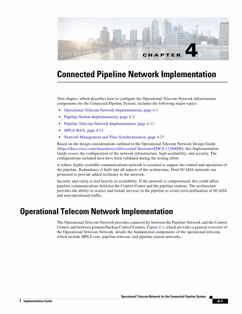
Connected Pipeline Network ImplementationThis chapter, which describes how to configure the Operational Telecom Network infrastructure components for the Connected Pipeline System, includes the following major topics:
• Operational Telecom Network Implementation, page 4-1
• Pipeline Station Implementation, page 4-2
• Pipeline Telecom Network Implementation, page 4-11
• MPLS WAN, page 4-21
• Network Management and Time Synchronization, page 4-27
Based on the design considerations outlined in the Operational Telecom Network Design Guide (https://docs.cisco.com/share/proxy/alfresco/url?docnum=EDCS-11280008), this Implementation Guide covers the configuration of the network infrastructure, high-availability, and security. The configurations included here have been validated during the testing effort.
A robust, highly available communications network is essential to support the control and operations of the pipeline. Redundancy is built into all aspects of the architecture. Dual SCADA networks are promoted to provide added resiliency to the network.
Security and safety is tied heavily to availability. If the network is compromised, this could affect pipeline communications between the Control Center and the pipeline stations. The architecture provides the ability to restrict and isolate services in the pipeline to avoid cross-pollination of SCADA and non-operational traffic.
Operational Telecom Network ImplementationThe Operational Telecom Network provides connectivity between the Pipeline Network and the Control Centers and between primary/backup Control Centers. Figure 4-1, which provides a general overview of the Operational Telecom Network, details the fundamental components of the operational telecom, which include MPLS core, pipeline telecom, and pipeline station networks.
4-1lecom Network for the Connected Pipeline System

Chapter 4 Connected Pipeline Network Implementation Pipeline Station Implementation
Figure 4-1 Operation Telecom Network
The Operational Telecom Network is broken into three fundamental areas:
• Core MPLS network, which provides a L3VPN backbone for connectivity. Separate L3VPN instances are deployed for SCADA communication. The MPLS core network will be able to communicate with the terminal stations on the two ends of the pipeline segment. In the implementation, the MPLS network has Cisco ISR 3945 series routers with OSPF and BGP connectivity to Control Centers. These ISR routers peer with Cisco ASR 90x series routers in the Control Centers and the pipeline terminal stations.
• The Operational Telecom Network is deployed using Layer 2 Ethernet rings that run along the pipeline from one terminal station to the other. Intermediate stations such as the pump/compressor and block valve stations are also included as part of the ring. Two sets of rings are deployed for SCADA communication to provide redundancy in the network. The ring network primarily uses the REP in the pipeline segment. EoMPLS is used in the MPLS network to complete the ring between the two terminal stations. A set of Cisco Industrial Ethernet 4000 and Cisco Industrial Ethernet 2000 series switches are deployed to form a ring architecture along the Pipeline Network.
• A pipeline station having SCADA connectivity will use one or both of the IE switches in the ring architecture. In the current implementation, certain RTUs with a single NIC connect only to one of the IE switches. However, RTUs with dual NIC capability will connect to both IE switches in the station for redundancy. In such a setup, the SCADA server in the Control Center will communicate with the active NIC at a given point of time.
Pipeline Station ImplementationIn the Oil and Gas pipeline, we come across several types of stations: the Terminal/Main Station, Pump Station, Block Valve Station, and Pipeline Inspection Gauge (PIG) Station. In the current implementation of Connected Pipeline, only three types of stations were deployed: a larger station such as the Terminal/Main Station and smaller stations such as Pump and Block Valve Stations. The architecture around the Pump and Block Valve Stations remained the same for the current implementation. Details about the stations can be found in the accompanying design document for Connected Pipeline.
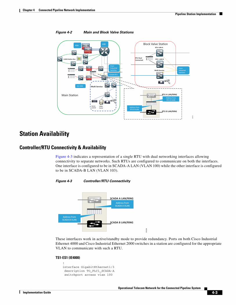
Figure 4-2 shows the architecture details around Terminal/Main and Block Valve Stations. The general concepts of implementation are already discussed in previous sections. This section points to salient implementation steps that are applicable to the station architecture.
B/Valve Main Sta�on Main Sta�on
Ac�ve/Standby ASA 5525x
Ac�ve/Standby ASA 5525x 5255x
ASR 903 Dual RP
ASR 903 Dual RP
RTU
RTU LAN A RTU LAN B Mul� Service
B/Valve B/Valve B/Valve
WAN to Control Center
EoMPLS PW’s per Service
Main CC Backup CC
MCC/BCC L3VPN x2 Core MPLS Network • L3VPN Service between the
Control Centers and the Pipeline • Customer owned
Pipeline Telecom • Op�cal fiber along the pipeline • Layer 2 Ethernet rings between
main sta�ons • Dual SCADA networks
Sta�on network • Sta�on RTUs dual-connected to
each SCADA network
3767
56
4-2Operational Telecom Network for the Connected Pipeline System
Implementation Guide
Chapter 4 Connected Pipeline Network Implementation Pipeline Station Implementation
Figure 4-2 Main and Block Valve Stations
Station Availability
Controller/RTU Connectivity & Availability
Figure 4-3 indicates a representation of a single RTU with dual networking interfaces allowing connectivity to separate networks. Such RTUs are configured to communicate on both the interfaces. One interface is configured to be in SCADA-A LAN (VLAN 100) while the other interface is configured to be in SCADA-B LAN (VLAN 103).
Figure 4-3 Controller/RTU Connectivity
These interfaces work in active/standby mode to provide redundancy. Ports on both Cisco Industrial Ethernet 4000 and Cisco Industrial Ethernet 2000 switches in a station are configured for the appropriate VLAN to communicate with such a RTU.
TS1-ES1 (IE4000)!interface GigabitEthernet1/3 description TO_PLC1_SCADA-A switchport access vlan 100
RTU A LAN/RING
RTU B LAN/RING
Address from RTU A VLAN
Address from RTU B VLAN
RTU Dual Connected
RTU LAN A
RTU LAN B
Mul� Service Cisco Industrial Switches
Mul� Service
Video Server
Access Control
61850 Sta�on Bus
ASR ASA
Cisco Industrial Switches
SCADA RTU
ISA 3000
Main Sta�on
Block Valve Sta�on
3767
57
SCADA A LAN/RING
SCADA B LAN/RING
Address from SCADA A VLAN
Address from SCADA B VLAN
3767
58
4-3Operational Telecom Network for the Connected Pipeline System
Implementation Guide

Chapter 4 Connected Pipeline Network Implementation Pipeline Station Implementation
switchport mode access!
TS2-ES2 (IE2000)!interface FastEthernet1/3 description TO_PLC1_SCADA-B switchport access vlan 103 switchport mode access!
Note Some RTUs have only one network interface for communication with SCADA server in Control Center. The appropriate switch port is configured depending on which VLAN the RTU is using to communicate with the server.
Dedicated Switch and VLAN
Cisco Industrial Ethernet 4000 and Cisco Industrial Ethernet 2000 series switches are deployed in each station. SCADA-A communication uses VLAN 100 and traverses only the Cisco Industrial Ethernet 4000 switches in the ring. SCADA-B communication uses VLAN 103 and traverses only the Cisco Industrial Ethernet 2000 switches.
The interfaces participating in the ring topology are configured as trunks, but only allow the SCADA relevant VLAN information.
TS1-ES1 (IE4000 switch)!interface GigabitEthernet1/1 description CONNECTION_TO_PS1-ES1::Gig1/2 switchport mode trunk switchport trunk allowed vlan 100!interface GigabitEthernet1/2 description CONNECTION_TO_TS1-RTR1::Gig0/3/1 switchport mode trunk switchport trunk allowed vlan 100!
TS1-ES2 (IE2000 switch)!interface FastEthernet1/1 description CONNECTION_TO_PS1-ES2::F1/2 switchport mode trunk switchport trunk allowed vlan 103!interface FastEthernet1/2 description CONNECTION_TO_TS1-RTR1::Gig0/3/2 switchport mode trunk switchport trunk allowed vlan 103!
4-4Operational Telecom Network for the Connected Pipeline System
Implementation Guide

Chapter 4 Connected Pipeline Network Implementation Pipeline Station Implementation
Layer 2 Redundancy with REP
SCADA-A VLAN 100 uses a REP segment 100 that traverses the Cisco Industrial Ethernet 4000 switches. The REP segment 100 terminates on one end at the edge router in the terminal station 1 (TS1-RTR1) while the preferred ALT port for the segment is configured on the other end at the edge router in the terminal station 2 (TS2-RTR2).
TS1-RTR1!rep admin vlan 100!!interface GigabitEthernet0/3/1 description CONNECTION_TO_TS1-ES1::Gig1/2 mtu 9216 no ip address load-interval 30 negotiation auto rep segment 100 edge cdp enable service instance trunk 1 ethernet encapsulation dot1q 100-101 rewrite ingress tag pop 1 symmetric bridge-domain from-encapsulation !!
TS1-ES1!interface GigabitEthernet1/1 description CONNECTION_TO_PS1-ES1::Gig1/2 switchport mode trunk switchport trunk allowed vlan 100 load-interval 30 rep segment 100!interface GigabitEthernet1/2 description CONNECTION_TO_TS1-RTR1::Gig0/3/1 rep segment 100!
TS2-RTR1!interface GigabitEthernet0/3/2 description CONNECTION_TO_TS2-ES2::Gig1/1 mtu 9216 no ip address load-interval 30 negotiation auto rep segment 103 edge cdp enable service instance trunk 1 ethernet encapsulation dot1q 102-103 rewrite ingress tag pop 1 symmetric bridge-domain from-encapsulation !!
4-5Operational Telecom Network for the Connected Pipeline System
Implementation Guide

Chapter 4 Connected Pipeline Network Implementation Pipeline Station Implementation
Platform Redundancy for Cisco ASR 903 and Cisco ASA 5525-X
In the terminal station, the edge router redundancy is provided by means of dual supervisors in the Cisco ASR 903 chassis. These supervisors are configured to behave in active/standby mode and configured for SSO.
TS1-RTR1 !redundancy mode sso!
TS1-RTR1#show platform Chassis type: ASR-903
Slot Type State Insert time (ago) --------- ------------------- --------------------- ----------------- 0/3 A900-IMA8T ok 7w0d 0/4 A900-IMA8S ok 7w0d R0 A900-RSP2A-64 ok, active 7w0d R1 A900-RSP2A-64 ok, standby 7w0d F0 ok, active 7w0d F1 ok, standby 7w0d P0 A900-PWR550-A ok 7w0d P1 Unknown N/A never P2 A903-FAN ok 7w0d
TS1-RTR1 #show redundancy state my state = 13 -ACTIVE peer state = 8 -STANDBY HOT Mode = Duplex Unit = Primary Unit ID = 48
Redundancy Mode (Operational) = ssoRedundancy Mode (Configured) = ssoRedundancy State = sso Maintenance Mode = Disabled Manual Swact = enabled Communications = Up
client count = 107 client_notification_TMR = 30000 milliseconds RF debug mask = 0x0
TS1RTR1_ASR903-O2803#
The Cisco ASA platform is deployed in the Control Center to provide firewall capability. A pair of Cisco ASA 5525-X platforms are set up in an active/standby mode for high availability. Both these firewalls are connected to the Cisco ASR 903 as shown in the topology. A failover link is configured between the two Cisco ASA 5525-Xs to determine the primary and secondary roles. The failover link is a directly-attached link between the two Cisco ASA 5525-Xs. This link can also be set up via an external switch.
Configure active/standby failover mode on each firewall and the failover link between the two (refer to Figure 4-4, Figure 4-5, and Figure 4-6).
Step 1 Choose High Availability and Scalability > Failover within the Device Management pane.
4-6Operational Telecom Network for the Connected Pipeline System
Implementation Guide

Chapter 4 Connected Pipeline Network Implementation Pipeline Station Implementation
Step 2 In the Setup tab, click Enable Failover. For greater security, enter a shared key in the appropriate field to encrypt the communications between the active and standby firewalls.
Step 3 Under LAN Failover, select a physical interface to transmit failover information. Fill in the Logical Name field with any desired value, and the Active IP and Standby IP fields (select any IP address range not already being used) and the Subnet Mask field (typically 255.255.255.252 for a point-to-point connection).
Step 4 Select the Preferred Role to identify whether this firewall should be the primary (active) or secondary (standby). Under State Failover, select a physical interface (this may be the same as LAN Failover interface, if desired).
Step 5 In the Interfaces tab, assign a standby IP address for each interface within the same subnet as the active one. For any interfaces that should be monitored for loss of connectivity to trigger a firewall failover, choose the Monitored option.
Step 6 In the Criteria tab, enter 1 as the Number of failed interfaces that triggers failover. Change values under Failover Poll Times as desired.
Step 7 Click Apply to make all changes take effect.
Step 8 Repeat the above steps for the second firewall (changing the Preferred Role accordingly).
Note When Stateful Failover is enabled, the active unit continually passes per-connection state information to the standby unit via the State Failover link.
Figure 4-4 Cisco ASA 5525-X Failover Configuration-1
4-7Operational Telecom Network for the Connected Pipeline System
Implementation Guide

Chapter 4 Connected Pipeline Network Implementation Pipeline Station Implementation
Figure 4-5 Cisco ASA 5525-X Failover Configuration-2
Figure 4-6 Cisco ASA 5525-X Failover Configuration-3
The equivalent CLI configuration for ASA failover is shown below:
!failoverfailover lan unit primaryfailover lan interface FAILOVER GigabitEthernet0/5 failover link FAILOVER GigabitEthernet0/5failover interface ip FAILOVER 10.10.1.1 255.255.255.0 standby 10.10.1.2!monitor-interface SCADA-Amonitor-interface L3VPN-SCADA-A!
On the redundant ASA equipment, the CLI equivalent will be:
!failoverfailover lan unit secondaryfailover lan interface FAILOVER GigabitEthernet0/5 failover link FAILOVER GigabitEthernet0/5failover interface ip FAILOVER 10.10.1.1 255.255.255.0 standby 10.10.1.2!monitor-interface SCADA-A monitor-interface L3VPN-SCADA-A !
4-8Operational Telecom Network for the Connected Pipeline System
Implementation Guide

Chapter 4 Connected Pipeline Network Implementation Pipeline Station Implementation
Station Security
Security for SCADA Traffic - Pipeline and Control Center
The redundant setup of Cisco ASA 5525-X firewall provide security for SCADA traffic between the Pipeline Network and the Control Center. The implementation steps for this are explained in Pipeline Telecom Security, page 4-19.
An extra level of security in the Pipeline Network infrastructure is provided in the following categories.
Shutdown Unused Ports
Any unused port on the Industrial Ethernet switch is explicitly placed in administratively shutdown mode.
! interface Gigabit Ethernet1/6 description UNUNSED_PORT shutdown!
IE4K-TS1-ES1-O3104#sh interface GigabitEthernet1/6GigabitEthernet1/6 is administratively down, line protocol is down (disabled) Hardware is Gigabit Ethernet, address is 64f6.9d95.e106 (bia 64f6.9d95.e106) Description: UNUSED_PORT MTU 1500 bytes, BW 10000 Kbit/sec, DLY 1000 usec, reliability 255/255, txload 1/255, rxload 1/255>> snip <<
Trunk Ports
In the current implementation, trunk ports on Cisco Industrial Ethernet 4000 and Cisco Industrial Ethernet 2000 switches are configured for explicit trunk with Dynamic Trunk Protocol (DTP) off. Only necessary VLANs are allowed on the trunks.
TS1-ES1 (IE4000 switch)!interface GigabitEthernet1/1 description CONNECTION_TO_PS1-ES1::Gig1/2 switchport mode trunk switchport trunk allowed vlan 100!
TS1-ES2 (IE2000 switch)!interface FastEthernet1/1 description CONNECTION_TO_PS1-ES2::F1/2 switchport mode trunk switchport trunk allowed vlan 103!
Port Security
Port Security is configured to limit unauthorized use of a switch ports. This feature is usually enabled on access ports connected to PLCs in the stations.
4-9Operational Telecom Network for the Connected Pipeline System
Implementation Guide

Chapter 4 Connected Pipeline Network Implementation Pipeline Station Implementation
In the following example, an access port on a Cisco Industrial Ethernet 4000 switch connected to a PLC is configured for port-security.
!interface GigabitEthernet1/3 description TO_PLC switchport access vlan 100 switchport mode access switchport port-security maximum 1 switchport port-security violation restrict switchport port-security mac-address 0001.2322.2625 switchport port-securityend!
TS2-ES1#show port-securitySecure Port MaxSecureAddr CurrentAddr SecurityViolation Security Action (Count) (Count) (Count)--------------------------------------------------------------------------- Gi1/3 1 1 0 Restrict
---------------------------------------------------------------------------Total Addresses in System (excluding one mac per port) : 2Max Addresses limit in System (excluding one mac per port) : 16384
TS2-ES1#TS2-ES1#sh port-security interface gigabitethernet 1/3 Port Security: EnabledPort Status: Secure-downViolation Mode: RestrictAging Time: 0 minsAging Type: Absolute SecureStatic Address Aging : Disabled Maximum MAC Addresses : 1Total MAC Addresses :1 Configured MAC Addresses : 1 Sticky MAC Addresses : 0>> snip <<
Infrastructure Management
In the current implementation, out-of-band (OOB) management is deployed for the management of network infrastructure. A dedicated VLAN 10 with IP address range of 10.27.x.x/16 is used within the lab infrastructure. SSH, a cryptographic network protocol, provides a secure channel for connecting to the networking infrastructure.
!aaa new-modelip domain name schneider-electric.com!!username testuser password 0 testpassword!ip ssh time-out 60 ip ssh version 1!line vty 0 4exec-timeout 0 0 password lab logging synchronoustransport preferred none transport input ssh!
PS1-ES1 #telnet 10.27.4.1Trying 10.27.4.1 ... % Connection refused by remote host
4-10Operational Telecom Network for the Connected Pipeline System
Implementation Guide

Chapter 4 Connected Pipeline Network Implementation Pipeline Telecom Network Implementation
PS1-ES1 # ssh -l testuser 10.27.4.1Password: TS1-ES1 >enPassword: TS1-ES1 #
Pipeline Telecom Network ImplementationThe Design Guide for the Connected Pipeline discusses many alternatives for the Pipeline Network such as Ethernet ring and one-over-one station hopping.
Figure 4-7 details the Operational Telecom Network that was validated for the Connected Pipeline System. Per the design, two Layer 2 Ethernet networks SCADA-A and SCADA-B rings provide segmentation and availability for the critical SCADA communications with two networks. The Ethernet runs between main stations (sometimes also called terminal stations) through several block valves or pump stations. The Ethernet rings will be "closed" using EoMPLS Pseudowire between the main stations and will be terminated at Layer 3 in the main stations.
Figure 4-7 Pipeline Telecom Ethernet Rings
A third Layer 2 ring may be dedicated for multiservice applications to promote segmentation and isolation of non-critical services.
Note In the current implementation, configurations necessary for multiservices were provisioned. However, the multiservices ring was not deployed.
Pipeline Telecom AvailabilityThe two SCADA networks namely SCADA-A and SCADA-B will run on separate physical links. Separate instances of logical segmentation are deployed in terms of VLAN. For the implementation purpose, the following scheme was deployed:
• SCADA-A—VLAN - 100; IP - 192.168.100.0/24
• SCADA-B—VLAN - 103; IP - 192.168.103.0/24
SCADA-A ring will terminate at the left terminal station (TS1). The redundant firewall setup in TS1 comprised of a pair of Cisco ASA 5525-Xs will act as default gateway for the SCADA-A segment.
Pump Sta�on 2 Block Valve Pump Sta�on 1
Terminal Sta�on 2 Terminal Sta�on 1
IE 4000 TS1-ES1
ASR 903 (Dual RP) TS2-RTR1
IE 4000 TS2-ES1
IE 3000 TS1-ES2
IE 4000 PS1-ES1
IE 4000 BV1-ES1
IE 4000 PS2-ES1
IE 3000 TS2-ES2
IE 3000 PS1-ES2
IE 3000 BV1-ES2
IE 3000 PS2-ES2
MPLS Core
Layer 2 Access – Resilient Ethernet
Protocol
Layer 2 Access – Resilient Ethernet
Protocol
ASR 903 (Dual RP) TS1-RTR1
ASA 5525x TS1-FRW
ASA 5525x TS2-FRW
3767
59
4-11Operational Telecom Network for the Connected Pipeline System
Implementation Guide

Chapter 4 Connected Pipeline Network Implementation Pipeline Telecom Network Implementation
SCADA-B ring will terminate at the right terminal station (TS2). The redundant firewall setup in TS2 comprised of a pair of Cisco ASA 5525-Xs will act as default gateway for the SCADA-B segment.
The Cisco ASA 5525-X is configured using ASDM. Information about downloading ASDM version 7.4, install and configuration can be found at the following URL:
• http://www.cisco.com/c/en/us/td/docs/security/asa/asa94/config-guides/asdm74/firewall/asdm-74-firewall-config.html
In addition to using the Cisco ASA 5525-X as a firewall, the device will also behave as the default gateway for the SCADA network in the pipeline.
Note The firewall located in Terminal Station 1 will be the default gateway for SCADA-A (VLAN 100). Firewall located in Terminal Station 2 will be the default gateway for SCADA-B (VLAN 103).
This guide assumes that the user has already performed the initial setup and hardening of the Cisco ASA. For more details on these configurations, refer to the following URL:
• http://www.cisco.com/c/en/us/support/security/asa-5500-series-next-generation-firewalls/products-in stallation-and-configuration-guides-list.html
Configuration steps using ASDM on Cisco ASA 5525-X located in Terminal Station 1 are described below:
Step 1 Configure interfaces for the SCADA-A LAN interface attached to the edge router. Refer to Figure 4-8.
a. Click Interfaces within the Device Setup pane.
b. Click Add to the right of the interface list, and then choose GigabitEthernet0/3.
c. Enter values for the VLAN ID, Subinterface ID, Interface Name, and Security Level fields.
-For the VLAN ID, enter value 100.
-For the Subinterface ID, enter value 100.
-For the Interface Name, enter SCADA-A.
-For the Security Level, enter 100
d. Choose the Enable Interface option.
e. Choose the Use Static IP option and enter the IP address and subnet mask for the interface.
f. If desired, fill in the Description field to help identify the purpose of this interface, and then click OK.
g. Click Apply to make all changes take effect.
4-12Operational Telecom Network for the Connected Pipeline System
Implementation Guide

Chapter 4 Connected Pipeline Network Implementation Pipeline Telecom Network Implementation
Figure 4-8 Default Gateway Setup on Cisco ASA 5525-X
Set up L3VPN interface using ASDM.
Step 2 Configure interfaces for the SCADA-A LAN interface attached to the edge router. Refer to Figure 4-9.
a. Choose Interfaces within the Device Setup pane.
b. Click Add to the right of the interface list, and then choose GigabitEthernet0/4.
c. Enter values for the VLAN ID, Subinterface ID, Interface Name, and Security Level fields.
-For the VLAN ID, enter value 4.
-For the Subinterface ID, enter value 4.
-For the Interface Name, enter L3VPN-SCADA-A.
-For the Security Level, enter 0:
d. Select the Enable Interface option.
e. Select the Use Static IP option and enter the IP Address, and Subnet Mask for the interface.
f. If desired, fill in the Description field to help identify the purpose of this interface, and then click OK.
g. Click Apply to make all changes take effect.
4-13Operational Telecom Network for the Connected Pipeline System
Implementation Guide

Chapter 4 Connected Pipeline Network Implementation Pipeline Telecom Network Implementation
Figure 4-9 L3VPN Interface Setup on Cisco ASA 5525-X
The firewall Cisco ASA 5525-X setup advertises the SCADA network to the ASR edge router via Enhanced Interior Gateway Routing Protocol (EIGRP). This network information is placed into appropriate VRF instance (VRF SCADA_A) in the ASR.
Step 3 Configure EIGRP as the dynamic routing protocol. Refer to Figure 4-10 and Figure 4-11. This is essential for the firewall and aggregation routers to exchange network reachability information between the Control Center environment and the Pipeline segment.
a. Choose Routing > EIGRP > Setup within the Device Setup pane.
b. In the Process Instances tab, enter the EIGRP Process number, and then click Advanced.
c. For the Router ID field, click either Automatic (to assign the highest local IP address as the ID) or IP Address (to assign an ID manually). Disable the Auto-Summary option and enable the Log Neighbor Changes and Log Neighbor Warnings options. Leave all other settings as default and then click OK.
d. In the Networks tab, define each subnet that should be advertised by EIGRP by clicking Add and filling in the IP Address and Netmask fields.
e. In the Passive Interfaces tab, select Suppress Routing Updates on All Interfaces. This prevents interfaces with IP addresses in the Networks list from attempting to form neighborships with adjacent devices. To add exceptions to this option for the industrial and Enterprise-facing interfaces and allow neighborships to form, click Add to select each interface and then click OK.
f. To enable authentication between EIGRP neighbors for increased security, select Interface under EIGRP in the Device Setup pane. Select the desired interface from the list and click Edit. Select Enable MD5 Authentication, and then enter a Shared Secret Key value and ID. Finally, click OK.
g. To enable summarization of advertised EIGRP routes for increased security and efficiency, choose EIGRP > Summary Address in the Device Setup pane. Click Add, and then enter values for the Summary IP Address, Netmask, and Interface that will advertise the summary route. Leave the Administrative Distance field blank and then click OK.
h. Click Apply to make all changes take effect.
4-14Operational Telecom Network for the Connected Pipeline System
Implementation Guide

Chapter 4 Connected Pipeline Network Implementation Pipeline Telecom Network Implementation
Figure 4-10 EIGRP Process Configuration on Cisco ASA 5525-X
Figure 4-11 EIGRP Process Configuration on Cisco ASA 5525-X (continued)
The equivalent CLI configuration for Steps 1-3 is shown below.
!namesname 192.168.100.0 SCADA-A description Gateway for SCADA-Aname 192.168.4.0 L3VPN-SCADA-A description L3VPNSCADA-A!interface GigabitEthernet0/3 description TO_SETS1RTR1::Gig0/3/3 & Gig0/4/3 no nameif no security-level no ip address!interface GigabitEthernet0/3.100 vlan 100 nameif SCADA-A
4-15Operational Telecom Network for the Connected Pipeline System
Implementation Guide

Chapter 4 Connected Pipeline Network Implementation Pipeline Telecom Network Implementation
security-level 100 ip address 192.168.100.1 255.255.255.0 standby 192.168.100.2 !!interface GigabitEthernet0/4 description TO_SETS1RTR1::Gig0/3/4 & Gig0/4/4 no nameif no security-level no ip address!interface GigabitEthernet0/4.4 vlan 4 nameif L3VPN-SCADA-A security-level 0 ip address 192.168.4.253 255.255.255.0 standby 192.168.4.254 !! router eigrp 10 auto-summary eigrp router-id 192.168.1.1 network L3VPN-SCADA-A 255.255.255.0 network SCADA-A 255.255.255.0!
Note An example of only the configuration for the firewall in Terminal Station 1 is provided below. The configuration of firewall in Terminal Station 2 will be similar and applicable to SCADA-B.
The Cisco ASR 903 edge router in the terminal station advertises these SCADA networks to the Control Center. Control Center applications will be able to reach PLCs on one or two SCADA networks. Details of RTU/Controller connectivity are discussed in a subsequent section.
• The edge router in TS1 (TS1-RTR1) will advertise SCADA-A network with a better metric compared to edge router in TS2 (TS2-RTR2)
• The edge router in TS2 (TS1-RTR2) will advertise SCADA-B network with a better metric compared to edge router in TS1 (TS2-RTR1)
EoMPLS Pseudowire
EoMPLS Pseudowire is configured on the edge routers in the terminal stations. This configuration helps complete the SCADA ring that runs along the pipeline segment. This pseudowire will be used during failure of connection along pipeline segment.
The SCADA-A terminates on the interface GigabitEthernet0/3/1 on the Cisco ASR 903.
!bridge-domain 100!l2 vfi repring1 manual vpn id 100 bridge-domain 100 neighbor 192.168.1.2 encapsulation mpls!!interface BDI100 no ip address encapsulation dot1Q 100!!interface GigabitEthernet0/3/1 description CONNECTION_TO_IE4K-1::Gig1/2
4-16Operational Telecom Network for the Connected Pipeline System
Implementation Guide

Chapter 4 Connected Pipeline Network Implementation Pipeline Telecom Network Implementation
mtu 9216 no ip address load-interval 30 negotiation auto rep segment 100 edge cdp enable service instance trunk 1 ethernet encapsulation dot1q 100-101 rewrite ingress tag pop 1 symmetric bridge-domain from-encapsulation !!
Note An example of configuration on edge router in Terminal Station 1 for SCADA-A network with VLAN100 is provided. The configuration of edge router in Terminal Station 2 for SCADA-B network with VLAN 103 will be similar.
Resilient Ethernet Protocol (REP)
The REP is a Cisco proprietary protocol that provides an alternative to the STP. REP provides a way to control network loops, handle link failures, and improve convergence time in the range of 50 -200 ms. It controls a group of ports connected in a segment, ensures that the segment does not create any bridging loops, and responds to link failures within the segment.
Refer to the REP white paper at the following URL:
• http://www.cisco.com/c/en/us/support/docs/lan-switching/ethernet/116384-technote-rep-00.html
In the current implementation (Figure 4-12), the REP edge ports are configured on the ASR 903s in the two terminal stations. For REP segment 100 corresponding to SCADA-A (VLAN 100), the preferred edge port is configured on the Cisco ASR 903 in the left terminal station (TS1-RTR1) and the alternate edge port is configured on Cisco ASR 903 in the right terminal station (TS2-RTR1). Under the steady state scenario of the REP functionality, all the SCADA-A traffic from pipeline segment is forwarded to the Control Center via terminal station 1.
Figure 4-12 REP Implementation
Under failure situation in the segment, the alternate port on the TS2-RTR1 detects the REP failure and transitions to forwarding state. Once the failure scenario is restored to normalcy, the alternate port will remain at the port of failure. In the current implementation, REP preemption for segment 100 (SCADA-A) is configured so that the ALT port returns to the Cisco ASR 903 on terminal station 2
3767
60
4-17Operational Telecom Network for the Connected Pipeline System
Implementation Guide

Chapter 4 Connected Pipeline Network Implementation Pipeline Telecom Network Implementation
(TS2-RTR1). The reason for such a configuration is to ensure that, under normal operating condition, Terminal Station 1 is designed to always be the exit point for SCADA-A (VLAN 100) and Terminal Station 2 is designed to always be the exit point for SCADA-B (VLAN 103)
Following is the configuration of REP on the edge routers in terminal stations.
TS1-RTR1!rep admin vlan 100!!interface GigabitEthernet0/3/1 description CONNECTION_TO_TS1-ES1::Gig1/2 mtu 9216 no ip address load-interval 30 negotiation auto rep segment 100 edge cdp enable service instance trunk 1 ethernet encapsulation dot1q 100-101 rewrite ingress tag pop 1 symmetric bridge-domain from-encapsulation !!!interface GigabitEthernet0/3/2 description CONNECTION_TO_TS1-ES2::Gig1/2 mtu 9216 no ip address load-interval 30 negotiation auto rep segment 103 edge preferred cdp enable service instance trunk 1 ethernet encapsulation dot1q 102-103 rewrite ingress tag pop 1 symmetric bridge-domain from-encapsulation !!
TS2-RTR1!rep admin vlan 103!!interface GigabitEthernet0/3/1 description CONNECTION_TO_TS2-ES1::Gig1/1 mtu 9216 no ip address load-interval 30 negotiation auto rep segment 100 edge preferred cdp enable service instance trunk 1 ethernet encapsulation dot1q 100-101 rewrite ingress tag pop 1 symmetric bridge-domain from-encapsulation !!interface GigabitEthernet0/3/2 description CONNECTION_TO_TS2-ES2::Gig1/1
4-18Operational Telecom Network for the Connected Pipeline System
Implementation Guide

Chapter 4 Connected Pipeline Network Implementation Pipeline Telecom Network Implementation
mtu 9216 no ip address load-interval 30 negotiation auto rep segment 103 edge cdp enable service instance trunk 1 ethernet encapsulation dot1q 102-103 rewrite ingress tag pop 1 symmetric bridge-domain from-encapsulation !!
Note REP Preemption is enabled at the privileged level and not configuration level.
The following is the configuration for SCADA-A VLAN 100 on TS1-RTR.
TS1-RTR1# rep preempt segment 100
While the Cisco ASR 903 edge routers behave as two edges of REP segment, the protocol should also be configured on the Industrial Ethernet switches in various stations to be part of the ring. The configuration on such devices are fairly simple.
!interface GigabitEthernet1/1 description CONNECTION_TO_PS1-ES1::Gig1/2 switchport mode trunk load-interval 30 rep segment 100!interface GigabitEthernet1/2 description CONNECTION_TO_TS1-RTR1::Gig0/3/1 switchport mode trunk load-interval 30 rep segment 100!
Pipeline Telecom SecurityFigure 4-13 provides an overview of the firewall and security implementation for the Connected Pipeline. A pair of Cisco ASA 5525-Xs in active/standby mode located in the terminal station provide dedicated firewall functionality, routing awareness, availability, and policy enforcement for the SCADA network. The firewall will explicitly restrict any access to the SCADA network from the other networks within the end-to-end pipeline. All traffic between the Control Center and the SCADA RTU segments will therefore be policed through the firewalls en route to the RTUs in the stations.
4-19Operational Telecom Network for the Connected Pipeline System
Implementation Guide

Chapter 4 Connected Pipeline Network Implementation Pipeline Telecom Network Implementation
Figure 4-13 Pipeline Telecom Security
To maintain the integrity and security of the SCADA traffic between the Pipeline Network and the Control Center, a redundant firewall setup is deployed in Terminal Stations. Per the design, pipeline station devices like RTUs and PLCs will be communicating only with the Production zone applications like RealTime servers, deployment servers, and historical servers in the Control Center.
The Cisco ASA platform is deployed in the Control Center to provide firewall capability for security. Access control policies are set up on the firewall to allow access between the Production zone and Pipeline stations.
Note Traffic from interfaces with a lower security level to interfaces with a higher security level is implicitly denied by default. However, to confirm complete isolation of all zones and prevent confusion, the user should overwrite these implicit rules with explicit ones.
Configure explicit rules between all zones and apply on the relevant interface (See Figure 4-14).
Step 1 Select Access Rules within the Firewall pane.
Step 2 For each interface, right-click the interface name and then select Add Access Rule.
Step 3 Create a Deny rule with Source as Any and Destination as Any, and then click OK.
Step 4 Click the new rule, and then click Move Down (down arrow) at the top of the pane until the rule is at the bottom of the interface rule list. Since firewall rules are evaluated in order, the Deny All rule must be at the bottom to only deny traffic that does not match any permit rules for the interface.
Step 5 Click Apply to make all changes take effect.
Main Sta�on
• Ac�ve/Standby ASA • Layer 3 Gateway RTU LAN A configured at this ASA • Port channel redundancy between ASR and the ASA • Rou�ng enabled between VRF on the ASR and the ASA
3767
61
4-20Operational Telecom Network for the Connected Pipeline System
Implementation Guide

Chapter 4 Connected Pipeline Network Implementation MPLS WAN
Figure 4-14 Access Control Configuration on Cisco ASA 5525-X
Note Figure 4-14 and the configuration steps indicated above are only examples of how to configure access rules on the firewall using ASDM. The access control policy is driven by Schneider's (or the customer's) confidential document. Due to the confidential nature of port names and numbers only the representation used during validation is shown below.
!access-list 101 extended permit ip <control-center-network> <pipeline-scada-a-network> necessary protocolsaccess-list 101 extended deny all!access-group 101 in interface L3VPN-SCADA-A !
MPLS WANThe WAN design for the Connected Pipeline (Figure 4-15) will use an MPLS backbone supporting L3VPN services from the pipeline main stations to the Control Centers and for communications between the Control Centers. The operating model of the MPLS WAN for this release of the validated design is of a company-owned MPLS Core.
4-21Operational Telecom Network for the Connected Pipeline System
Implementation Guide

Chapter 4 Connected Pipeline Network Implementation MPLS WAN
Figure 4-15 MPLS WAN High Level Architecture
MPLS WAN AvailabilityFigure 4-16 depicts how the MPLS WAN core network helps pipeline terminal stations communicate with the Control Center environment. The Pipeline Network consisting of two SCADA rings are terminated at two different terminal stations. The terminal station sometimes is also called the main station. The SCADA-A ring is terminated at the left terminal station while SCADA-B is terminated at the right terminal station. Both terminal stations are connected to the MPLS WAN core network for connectivity to the Control Center.
Figure 4-16 MPLS WAN Availability
MPLS WAN
VRF SCADA RTU LAN A
VRF SCADA
VRF SCADA VRF
Mul�service
VRF Mul�service
Main CC Backup CC
VRF Mul�service
VRF SCADA RTU LAN B
VRF Mul�service
3767
62
3767
63
4-22Operational Telecom Network for the Connected Pipeline System
Implementation Guide

Chapter 4 Connected Pipeline Network Implementation MPLS WAN
Note The Connected Pipeline design calls for two sets of Control Centers as seen in Figure 2-2 on page 2-2. One will be the Main Control Center and the other will be the Backup Control Center. In the current implementation, Backup Control Center was not deployed. All communication from pipeline stations will be with the Main Control Center.
MPLS Core Router Platform Redundancy
A Cisco ASR 903 router with power supply and dual supervisor capability is deployed in each terminal station. This router provides redundancy in terms of route processors and also dual physical connection to the core network. The connection to the MPLS core network is spread across different Ethernet modules on the router to ensure failure of a module has minimal impact on core services.
The following configuration is necessary on the ASR routers to communicate with the MPLS core network.
Note Shown here is the configuration from TS1-RTR1.
!mpls label protocol ldp!
Loopback interfaces are configured on a router for variety of purposes. Loopback interfaces remain in an operationally up state as long as the router is functionally up. In this setup, loopback interface is configured and is used as an identifier with MPLS, routing protocols like OSPF and BGP:
!interface Loopback0description LOOPBACK_ROUTER_IDip address 192.168.1.1 255.255.255.255!
Configure the interfaces facing the MPLS Network router and enable MPLS:
!interface GigabitEthernet0/3/0 description TO-WAN_CORE2::Gig0/1 mtu 9216 ip address 192.168.20.3 255.255.255.254 load-interval 30 negotiation auto mpls ip cdp enable!!interface GigabitEthernet0/4/7 description TO-WAN_CORE1::Gig0/0 mtu 9216 ip address 192.168.30.2 255.255.255.254 load-interval 30 negotiation auto mpls ip cdp enable!
4-23Operational Telecom Network for the Connected Pipeline System
Implementation Guide

Chapter 4 Connected Pipeline Network Implementation MPLS WAN
Configure the aggregation router to communicate with the ISR routers within MPLS Network (WAN core) using Open Shortest Path First (OSPF). For exchange of network information between Pipeline Networks and Control Center, configure the router to peer with the MPLS Network using BGP.
Note For the implementation, 192.168.1.1 and 192.168.1.2 are routers on two ends of the Pipeline Network. 192.168.1.4 and 192.168.1.5 are the two edge routers within the Control Center.
!router ospf 1 router-id 192.168.1.1 network 192.168.1.1 0.0.0.0 area 0 network 192.168.20.2 0.0.0.1 area 0 network 192.168.30.2 0.0.0.1 area 0!
!router bgp 10 bgp router-id 192.168.1.1 bgp log-neighbor-changes no bgp default ipv4-unicast neighbor 192.168.1.2 remote-as 10 neighbor 192.168.1.2 update-source Loopback0 neighbor 192.168.1.4 remote-as 10 neighbor 192.168.1.4 update-source Loopback0 neighbor 192.168.1.5 remote-as 10 neighbor 192.168.1.5 update-source Loopback0! address-family ipv4 neighbor 192.168.1.2 activate neighbor 192.168.1.4 activate neighbor 192.168.1.5 activate exit-address-family!
Remote Loop-Free Alternate Fast Reroute
Remote Loop-Free Alternate Fast Reroute (LFA-FRR) is deployed in the MPLS core network to support local-protection and fast failover. This feature offers an alternative to the MPLS TE-FRR feature to minimize packet loss due to link or node failure.
LFA-FRR enables a backup route to avoid traffic loss if a network fails. The backup routes (repair paths) are pre-computed and installed in the router as the backup for the primary paths. After the router detects a link or adjacent node failure, it switches to the backup path to avoid traffic loss.
LFA is a node other than the primary neighbor. Traffic is redirected to an LFA after a network failure. An LFA makes the forwarding decision without any knowledge of the failure. An LFA must neither use a failed element nor use a protecting node to forward traffic. An LFA must not cause loops. By default, LFA is enabled on all supported interfaces as long as the interface can be used as a primary path.
From the pipeline terminal stations (TS1), we have two alternate paths to reach the Control Center via the MPLS cloud: The primary path will be via Core Router 2 and the alternate path is Core Router 1.
OSPF is the routing protocol deployed in the core network.
Deploying Remote LFA FRR feature in the MPLS core will help determine the backup path under a network failure (node/link) scenario. The backup path is installed in the router. When a router senses network failure, it switches to backup path to avoid traffic loss.
!
4-24Operational Telecom Network for the Connected Pipeline System
Implementation Guide

Chapter 4 Connected Pipeline Network Implementation MPLS WAN
mpls ldp explicit-nullmpls ldp session protectionmpls ldp discovery targeted-hello accept!!!router ospf 1 fast-reroute per-prefix enable prefix-priority low fast-reroute per-prefix remote-lfa area 0 tunnel mpls-ldp!
MPLS WAN SegmentationThe segmentation of SCADA and multiservices traffic is kept logically separate in the MPLS core as depicted in Figure 4-17. This is accomplished using the L3VPN services. The L3VPN services are mapped into VRF instances on edge routers both in the terminal stations and the Control Center.
Figure 4-17 MPLS WAN Segmentation
SCADA-A and SCADA-B are the two VRF instances created for the redundant networks in the pipeline. SCADA-A VRF instance is configured on TS1-RTR1 as the Terminal Station 1 is designed to be the primary exit point for the Pipeline Network. SCADA-B VRF instance is configured on TS2-RTR1.
SCADA-A network is used for primary communication. If the Control Center servers fail to reach PLCs on the SCADA-A, redundant network SCADA-B will be used for communication.
Note Multiservices was not part of the validation. However, the routers are provisioned to support such a configuration.
Configuration on TS1-RTR1:
!ip vrf forwarding!ip vrf SCADA_A rd 100:1 route-target export 100:1 route-target import 100:1
MPLS WAN
VRF SCADA RTU LAN A
VRF SCADA
VRF SCADA VRF
Mul�service
VRF Mul�service
Main CC Backup CC
VRF Mul�service
VRF SCADA RTU LAN B
VRF Mul�service
3767
64
4-25Operational Telecom Network for the Connected Pipeline System
Implementation Guide

Chapter 4 Connected Pipeline Network Implementation MPLS WAN
!ip vrf MULTI_SERVICES rd 100:3 route-target export 100:3 route-target import 100:3!
The aggregation router communicates internally within the terminal station with firewall assembly. More details around this setup is provided in Platform Redundancy for Cisco ASR 903 and Cisco ASA 5525-X, page 4-6.
!interface BDI4 description L3VPN-SCADA_A ip vrf forwarding SCADA_A ip address 192.168.4.1 255.255.255.0 ip summary-address eigrp 10 0.0.0.0 0.0.0.0!!interface BDI120 ip vrf forwarding MULTI_SERVICES ip address 192.168.105.2 255.255.255.0 encapsulation dot1Q 105 vrrp 105 ip 192.168.105.1 vrrp 105 priority 110!
The aggregation router uses EIGRP as the routing protocol to learn about the Pipeline Networks.
Note This router obtains this information from the firewall assembly acting as the default gateway for the Pipeline Network. This firewall/gateway aspect will be covered in Network Management and Time Synchronization, page 4-27.
!router eigrp 10 ! address-family ipv4 vrf SCADA_A network 192.168.4.0 autonomous-system 10 eigrp router-id 192.168.1.1 exit-address-family !
The Pipeline Network information learned is then advertised to the MPLS Network.
!router bgp 10!! address-family vpnv4 neighbor 192.168.1.2 activate neighbor 192.168.1.2 send-community extended neighbor 192.168.1.4 activate neighbor 192.168.1.4 send-community extended neighbor 192.168.1.5 activate neighbor 192.168.1.5 send-community extended neighbor 192.168.1.6 activate neighbor 192.168.1.6 send-community extended neighbor 192.168.1.7 activate neighbor 192.168.1.7 send-community extended
4-26Operational Telecom Network for the Connected Pipeline System
Implementation Guide

Chapter 4 Connected Pipeline Network Implementation Network Management and Time Synchronization
exit-address-family! address-family ipv4 vrf SCADA_A redistribute connected exit-address-family ! address-family ipv4 vrf MULTI_SERVICES redistribute connected exit-address-family !
In the current implementation, two terminal stations advertise the Pipeline Network segment to the Control Center via the MPLS core network. The design calls for Terminal Station 1 to be the exit point for SCADA-A segment while Terminal Station 2 to be the exit point for SCADA-B segment. For the purpose of implementation, IP address ranges for the Pipeline Network are as follows:
• SCADA-A Network—192.168.100.0/24
• SCADA-B Network—192.168.103.0/24
Note The only configuration relevant to the aggregation router in Terminal Station 1 is portrayed at this point. Configuration of the aggregate router in the Terminal Station 2 will be very similar except that it will be focused more towards SCADA-B.
Network Management and Time Synchronization
Network ManagementIn the current implementation of Operational Telecom Network, network management of the equipment is spread across using multiple tools that are described below.
Cisco Adaptive Security Device Manager
The Cisco ASA 5525x within the terminal/main stations used as a firewall is managed by using ASDM. The ASDM user interface (Figure 4-18) provide easy access to configure the interface, routing, firewall policy and general management of the firewall. ASDM version 7.4 was used in the implementation to manage Cisco ASA 5525x with image version 9.2.
Note ASDM supports many ASA versions. ASDM documentation and online help includes all of the latest features supported by the ASA.
4-27Operational Telecom Network for the Connected Pipeline System
Implementation Guide

Chapter 4 Connected Pipeline Network Implementation Network Management and Time Synchronization
Figure 4-18 ASDM User Interface
SNMP and Logging Server
SNMP network management is implemented on the network equipment within the Control Center. The SNMP manager is located within the Control Center in the production zone. The equipment is configured to send traps to this SNMP manager.
!snmp-server group STRUXURELAB v3 auth snmp-server user lab STRUXURELAB v3 encrypted auth md5 36:e3:70:34:95:8e:ce:00:3a:80:73:e4:7f:dc:cd:a4 snmp-server host SCADA-A 192.168.120.91 trap version 3 labsnmp-server location CDCsnmp-server contact [email protected] community *****!The SNMP Manager host machine also acts as the logging server located within the Control Center. Network equipment are configured to send logs to this logging host.!logging enablelogging timestamplogging buffer-size 1048576logging buffered debugginglogging asdm informationallogging host SCADA-A 192.168.120.91!
Out of Band Management
In the current implementation of Operational Telecom Network, the OOB management network is deployed to provide dedicated management of the infrastructure. Refer to Figure 4-19 for a representative network for OOB management in the validation lab setup.
4-28Operational Telecom Network for the Connected Pipeline System
Implementation Guide

Chapter 4 Connected Pipeline Network Implementation Network Management and Time Synchronization
Figure 4-19 Out of Band Management
VLAN 10 is the dedicated VLAN used for this OOB management. Functionality of this OOB management includes:
• Console access to any networking equipment such as Cisco IE 4000 switches, Cisco IE 2000 switches, ASA firewall, and Cisco ASR 903 WAN edge routers
• FTP/TFTP servers for any file transfer
Time Synchronization
In the current implementation of Operational Telecom Network, a time source is set up in the Control Center production zone. The clock source is configured to propagate the accurate time information with a stratum level 4. Networking equipment within the operation telecom and pipeline stations are configured to reference this time source for synchronization.
Note For the lab setup, stratum 4 was configured.
NTP Source!interface GigabitEthernet0/0/0 ip address 192.168.120.177 255.255.255.0 ntp broadcast !ntp master 4!
NTP-SERVER#sh ntp associations
address ref clock st when poll reach delay offset disp*~127.127.1.1 .LOCL. 3 9 16 377 0.000 0.000 1.204 * sys.peer, # selected, + candidate, - outlyer, x falseticker, ~ configured
NTP-SERVER #sh ntp status Clock is synchronized, stratum 4, reference is 127.127.1.1 nominal freq is 250.0000 Hz, actual freq is 250.0000 Hz, precision is 2**10
VPN to Schneider Firewall
172.22.80.x/26
.1 Terminal Server
Windows PC
.10
.11
Terminal Server Connec�ons (to console port of routers)
Rtr1
Rtr2
con
con
Management 10.27.0.0/16
10.27.0.254/16
E0/0 E0/1
E0/0
E0/0
10.27.1.2/16
10.27.1.1/16
From Internet
Linux (FTP/TFTP)
E0/1
10.27.0.5/16 .12
E0/0
3767
65
4-29Operational Telecom Network for the Connected Pipeline System
Implementation Guide

Chapter 4 Connected Pipeline Network Implementation Network Management and Time Synchronization
ntp uptime is 8731900 (1/100 of seconds), resolution is 4000reference time is DA8315F8.6353F8E0 (13:58:48.388 CST Thu Mar 3 2016)clock offset is 0.0000 msec, root delay is 0.00 msecroot dispersion is 2.18 msec, peer dispersion is 1.20 msecloopfilter state is 'CTRL' (Normal Controlled Loop), drift is 0.000000000 s/ssystem poll interval is 16, last update was 0 sec ago.NTP-SERVER #sh clock 13:58:50.420 CST Thu Mar 3 2016
Other equipment (shown here is an example configuration on the switch within Terminal Station 1):
! ntp server 192.168.120.177 prefer!
TS1ES1# sh ntp associations address ref clock st when poll reach delay offset disp*~192.168.120.177 127.127.1.1 4 29 128 377 0.3 0.80 16.1 * master (synced), # master (unsynced), + selected, - candidate, ~ configuredTS1ES1#
TS1ES1#sh ntp status Clock is synchronized, stratum 5, reference is 192.168.120.177nominal freq is 286.1023 Hz, actual freq is 286.1284 Hz, precision is 2**19ntp uptime is 7075000 (1/100 of seconds), resolution is 3496reference time is DA7951CE.D0CD7FC7 (05:11:26.815 EST Thu Feb 25 2016)clock offset is -24.2617 msec, root delay is 8.67 msecroot dispersion is 51.89 msec, peer dispersion is 1.11 msecloopfilter state is 'CTRL' (Normal Controlled Loop), drift is -0.000091531 s/ssystem poll interval is 1024, last update was 552 sec ago.
TS1ES1#sh run | i ntpntp maxdistance 15ntp server 192.168.120.177TS1ES1#
4-30Operational Telecom Network for the Connected Pipeline System
Implementation Guide

Operational TeImplementation Guide
C H A P T E R 5
Operational Telecom Network: ValidationThis chapter includes the following major topics:
• Functionality Testing, page 5-1
• High Availability Testing, page 5-1
• Security Testing, page 5-2
Functionality, high availability, and security testing were performed as part of the Operational Telecom Network validation. Detailed information on various options can be found in the Design Guide.
Functionality TestingFunctional testing was validated once the telecom operation was up and running. The edge routers in terminal stations were able to reach the Control Center through the configured VRF instance. Traffic from Control Center to SCADA-A LAN flows through Terminal Station 1 while traffic from Control Center to SCADA-B LAN flows through Terminal Station 2. PLCs configured for both SCADA-A and SCADA-B VLANs could reach their respective default gateways on the firewall assembly.
The SCADA application servers in the production zone of the Control Center were polling/monitoring information from the pipeline PLCs. Policy set on the firewall controlled the access between the Control Center and the Pipeline Network. Only SCADA application servers in the Production zone were granted access for the Pipeline Network. Industrial Ethernet access switches along the pipeline provided communication path for PLCs in the pipeline.
High Availability TestingEdge router could withstand supervisor failure in the redundant supervisor setup on Cisco ASR 903s. Edge routers were able to withstand path failure via the MPLS core network by virtue of LFA-FRR.
Traffic re-convergence in pipeline segment failure was verified by reloading of IE switch and shutdown of ports on IE switch. Edge router failure/reload to simulate loss of communication to a terminal station where the traffic reconverged via the other terminal station on alternate LAN.
The system was validated for high availability in all of the following scenarios:
• Failure—Physical link, node, line card, firewall, power
• Reload—Edge router, Supervisor failure in edge router, Industrial Ethernet switch, ASA 5525-X firewall
5-1lecom Network for the Connected Pipeline System

Chapter 5 Operational Telecom Network: Validation Security Testing
Security TestingSecurity testing was completed verifying VRF instances on the edge routers, firewall policies and allowed VLANs in the Cisco IE 4000 and Cisco IE 2000 switches. The Control Center network was seen in the appropriate VRF instance on the edge routers in the terminal stations. This information was redistributed internally in the terminal station to firewall.
The firewall policy definition provided access only between the Pipeline Network and production zone in the Control Center. All the unused ports on the IE switches were configured for administrative shutdown mode. All ports on IE switches connected to PLCs were configured for port-security restrict mode.
5-2Operational Telecom Network for the Connected Pipeline System
Implementation Guide

Operational TeImplementation Guide
C H A P T E R 6
Operational Telecom Network: VerificationThis chapter, which describes verification of the Operational Telecom Network from functional, security and redundancy standpoints, includes the following major topics:
• Functional Verification - Communication between Edge Router in Terminal Station 1 and Control Center, page 6-1
• ASA/Firewall Failover, page 6-2
Functional Verification - Communication between Edge Router in Terminal Station 1 and Control Center
This section outlines verification of edge router in Terminal Station 1 having network reachability information for the Control Center production zone. Some of the verification includes route table look up in edge routers, firewall/gateway route look up, and application servers receiving data from field devices.
Figure 6-1 shows the RealTime application server monitoring the field device.
Figure 6-1 Verification: Production RealTime Server Polling PLCs in Pipeline Station
Both the Pipeline Network segment 192.168.100.0/24 and Production Zone Network 192.168.120.0/24 can be seen in the route table of the edge router in the following CLI output.
TS1-RTR1#sh ip route vrf SCADA_ARouting Table: SCADA_A
6-1lecom Network for the Connected Pipeline System

Chapter 6 Operational Telecom Network: Verification ASA/Firewall Failover
Codes: L - local, C - connected, S - static, R - RIP, M - mobile, B - BGP D - EIGRP, EX - EIGRP external, O - OSPF, IA - OSPF inter area N1 - OSPF NSSA external type 1, N2 - OSPF NSSA external type 2 E1 - OSPF external type 1, E2 - OSPF external type 2 i - IS-IS, su - IS-IS summary, L1 - IS-IS level-1, L2 - IS-IS level-2 ia - IS-IS inter area, * - candidate default, U - per-user static route o - ODR, P - periodic downloaded static route, H - NHRP, l - LISP a - application route + - replicated route, % - next hop override, p - overrides from PfR Gateway of last resort is 0.0.0.0 to network 0.0.0.0 D* 0.0.0.0/0 is a summary, 02:22:10, Null0 192.168.4.0/24 is variably subnetted, 2 subnets, 2 masksC 192.168.4.0/24 is directly connected, BDI4L 192.168.4.1/32 is directly connected, BDI4D 192.168.100.0/24 [90/3072] via 192.168.4.253, 02:22:10, BDI4B 192.168.120.0/24 [200/100] via 192.168.1.4, 02:19:36B 192.168.122.0/24 [200/0] via 192.168.1.4, 05:15:54B 192.168.125.0/24 [200/100] via 192.168.1.4, 02:19:36
TS1-RTR1#
Route details from edge router to SCADA RealTime Server in Control Center:
TS1-RTR1#sh bgp vpnv4 uni vrf SCADA_A 192.168.120.83BGP routing table entry for 100:1:192.168.120.0/24, version 5072Paths: (2 available, best #2, table SCADA_A) Not advertised to any peer Refresh Epoch 1 Local 192.168.1.5 (metric 3) (via default) from 192.168.1.5 (192.168.1.5) Origin incomplete, metric 200, localpref 100, valid, internal Extended Community: RT:100:1 Cost:pre-bestpath:128:3072 0x8800:32768:0 0x8801:10:512 0x8802:65281:2560 0x8803:65281:1500 0x8806:0:0 mpls labels in/out nolabel/46 rx pathid: 0, tx pathid: 0 Refresh Epoch 2 Local 192.168.1.4 (metric 3) (via default) from 192.168.1.4 (192.168.1.4) Origin incomplete, metric 100, localpref 100, valid, internal, best Extended Community: RT:100:1 Cost:pre-bestpath:128:3072 0x8800:32768:0 0x8801:10:512 0x8802:65281:2560 0x8803:65281:1500 0x8806:0:0 mpls labels in/out nolabel/36 rx pathid: 0, tx pathid: 0x0TS1-RTR1#
ASA/Firewall Failover The following output shows the many options available to verify the ASA failover states:
TS1-FRW1# show failover DescriptorShow failover interface descriptors. Two numbers areshown for each interface. When exchanging information regarding a particular interface, this unit uses the first number in messages it sends to its peer. And it expects the second number in messages it receives from its peer. For troubleshooting, collect the show output from both units and verify that the numbers match.Exec Show failover command execution informationHistory Show failover switching historyInterfaceShow failover command interface informationState Show failover internal state informationStatisticsShow failover command interface statistics information
6-2Operational Telecom Network for the Connected Pipeline System
Implementation Guide

Chapter 6 Operational Telecom Network: Verification ASA/Firewall Failover
Some of the more frequently-used commands are detailed below:
• show failover—This command serves as a starting point for troubleshooting and provides a detailed summary of all aspects of the failover pair. These include: whether failover is enabled, the current unit's configured role (primary or secondary), the failover interface and its status, polling timer values, software versions of both units, timestamp of last failover event, active and standby status of both units, how long the currently-active unit has been active, all monitored interfaces and their status and statistics related to stateful failover.
An example of the command output is shown below:
TS1-FRW# show failover Failover On Failover unit PrimaryFailover LAN Interface: FAILOVER GigabitEthernet0/5 (up)Unit Poll frequency 1 seconds, holdtime 15 secondsInterface Poll frequency 5 seconds, holdtime 25 secondsInterface Policy 1Monitored Interfaces 3 of 216 maximumMAC Address Move Notification Interval not setVersion: Ours 9.2(3)4, Mate 9.2(3)4Last Failover at: 10:40:33 UTC Apr 26 2016
This host: Primary - Active Active time: 1203990 (sec)slot 0: ASA5525 hw/sw rev (1.0/9.2(3)4) status (Up Sys) Interface LABNETWORK (172.18.133.38): Normal (Not-Monitored) Interface management (10.27.28.8): Normal (Waiting) Interface SCADA-A (192.168.100.1): Normal (Waiting) Interface L3VPN-SCADA-A (192.168.4.253): Normal (Waiting)
Other host: Secondary - Failed Active time: 0 (sec)slot 0: ASA5525 hw/sw rev (1.0/9.2(3)4) status (Up Sys) Interface LABNETWORK (0.0.0.0): Normal (Not-Monitored) Interface management (0.0.0.0): Normal (Waiting) Interface SCADA-A (0.0.0.0): No Link (Waiting) Interface L3VPN-SCADA-A (0.0.0.0): No Link (Waiting)
Stateful Failover Logical Update StatisticsLink : FAILOVER GigabitEthernet0/5 (up)Stateful Obj xmit xerr rcv rerr General 385585 0 160486 0 sys cmd 160486 0 160486 0 up time 0 0 0 0 RPC services 0 0 0 0 TCP conn 0 0 0 0 UDP conn 0 0 0 0 ARP tbl 225098 0 0 0 Xlate_Timeout 0 0 0 0 IPv6 ND tbl 0 0 0 0 VPN IKEv1 SA 0 0 0 0 VPN IKEv1 P2 0 0 0 0 VPN IKEv2 SA 0 0 0 0 VPN IKEv2 P2 0 0 0 0 VPN CTCP upd 0 0 0 0 VPN SDI upd 0 0 0 0 VPN DHCP upd 0 0 0 0 SIP Session 0 0 0 0 Route Session 0 0 0 0 Router ID 0 0 0 0 User-Identity 1 0 0 0 CTS SGTNAME 0 0 0 0
CTS PAC 0 0 0 0 TrustSec-SXP 0 0 0 0 IPv6 Route 0 0 0 0
6-3Operational Telecom Network for the Connected Pipeline System
Implementation Guide

Chapter 6 Operational Telecom Network: Verification ASA/Firewall Failover
STS Table 0 0 0 0
Logical Update Queue Information Cur Max TotalRecv Q: 0 14 160487Xmit Q: 0 14 1037550
TS1-FRW#
• show failover history—This command provides a timestamped history for the current unit of all state changes since coming online. If a unit is in an unexpected or failed state, this command can indicate what happened just before the unit arrived at this state. An example of the command output for a normally functioning active unit is shown below:
TS1-FRW# show failover history ==========================================================================From State To State Reason==========================================================================12:06:59 UTC Apr 25 2016Not Detected Disabled No Error
10:39:47 UTC Apr 26 2016Disabled Negotiation Set by the config command
10:40:33 UTC Apr 26 2016Negotiation Just Active No Active unit found
10:40:33 UTC Apr 26 2016Just Active Active Drain No Active unit found
10:40:33 UTC Apr 26 2016Active Drain Active Applying Config No Active unit found
10:40:33 UTC Apr 26 2016Active Applying Config Active Config Applied No Active unit found
10:40:33 UTC Apr 26 2016Active Config Applied Active No Active unit found
==========================================================================TS1-FRW#
• show failover state—This command provides the status of both members of the failover pair: whether configured as primary or secondary, and whether in active or standby mode. It also indicates the reason for the most recent failure event of either unit and the timestamp of that event. An example of the command output for a normally functioning failover pair is shown below:
TS1-FRW# show failover state
State Last Failure Reason Date/TimeThis host - Primary Active NoneOther host - Secondary Failed Ifc Failure 10:47:41 UTC Apr 26 2016 SCADA-A: No Link L3VPN-SCADA-A: No Link
====Configuration State===Sync Done
====Communication State===Mac set
TS1-FRW#
6-4Operational Telecom Network for the Connected Pipeline System
Implementation Guide

Operational TelecomImplementation Guide
A
P P E N D I X A Related DocumentationThis Appendix includes the following major topics:
• Network Infrastructure, page A-1
• Security, page A-2
• Network Time Protocol, page A-2
Network InfrastructureCisco ASR 900 Router Series Configuration Guide:
• http://www.cisco.com/c/en/us/td/docs/routers/asr903/software/guide/chassis/xe-3s/asr900-router-cfg-book.html
Cisco ASR 903 Router Chassis Software Configuration Guide:
• http://www.cisco.com/c/en/us/td/docs/wireless/asr_900/software/guide/chassis/ASR903-Chassis-SW.pdf
IP Routing: BGP Configuration Guide, Cisco IOS XE Release 3S (Cisco ASR 900 Series):
• http://www.cisco.com/c/en/us/td/docs/ios-xml/ios/iproute_bgp/configuration/xe-3s/asr903/irg-xe-3s-asr903-book.pdf
MPLS Basic Configuration Guide, Cisco IOS XE Release 3S (ASR 900):
• http://www.cisco.com/c/en/us/td/docs/ios-xml/ios/mp_basic/configuration/xe-3s/asr903/mp-basic-xe-3s-asr903-book.pdf
Cisco Industrial Ethernet 4000 Series Switches Data Sheet:
• http://www.cisco.com/c/en/us/products/collateral/switches/industrial-ethernet-4000-series-switches/datasheet-c78-733058.html
Cisco Industrial Ethernet 4000 Series Switch Configuration Guide:
• http://www.cisco.com/c/en/us/td/docs/switches/lan/cisco_ie4000/software/release/15-2_2_ea/configuration/guide/scg-ie4000.html
Cisco Industrial Ethernet 2000 Series Switches Data Sheet:
• http://www.cisco.com/c/en/us/products/collateral/switches/industrial-ethernet-2000-series-switches/datasheet-c78-730729.html
Cisco Industrial Ethernet 2000 Series Switch Configuration Guide:
A-1 Network for the Connected Pipeline System

Appendix A Related Documentation Security
• http://www.cisco.com/c/en/us/td/docs/switches/lan/cisco_ie2000/software/release/15_2_2_e/configuration/guide/scg-ie2000.html
Security Cisco ASA 5505 Adaptive Security Appliance and ASA 5500-X Series Next-Generation Firewalls Data Sheet:
• http://www.cisco.com/c/en/us/products/collateral/security/asa-5500-series-next-generation-firewalls/data_sheet_c78-701253.html
Cisco ASA Series General Operations CLI Configuration Guide, 9.2:
• http://www.cisco.com/c/en/us/td/docs/security/asa/asa92/configuration/general/asa-general-cli.pdf
Cisco ASA Series General Operations ASDM Configuration Guide, 7.3:
• http://www.cisco.com/c/en/us/td/docs/security/asa/asa93/asdm73/general/asa-general-asdm.pdf
Cisco ASA Series Firewall ASDM Configuration Guide, 7.3:
• http://www.cisco.com/c/en/us/td/docs/security/asa/asa93/asdm73/firewall/asa-firewall-asdm.pdf
Configuring Simple Network Management Protocol (SNMP):
• http://www.cisco.com/c/en/us/td/docs/app_ntwk_services/data_center_app_services/css11500series/v8-20/configuration/administration/guide/admgd/SNMP.html
Configuring Secure Shell on Routers and Switches Running Cisco IOS:
• http://www.cisco.com/c/en/us/support/docs/security-vpn/secure-shell-ssh/4145-ssh.html#sshvvs
Network Time ProtocolWindows Time Service Technical Reference:
• https://technet.microsoft.com/en-us/library/cc773061%28v=ws.10%29.aspx
Network Time Protocol: Best Practices White Paper:
• http://www.cisco.com/c/en/us/support/docs/availability/high-availability/19643-ntpm.html
Windows Time Service Technical Reference:
• https://technet.microsoft.com/en-us/library/cc773061.aspx
A-2Operational Telecom Network for the Connected Pipeline System
Implementation Guide

Operational TelecomImplementation Guide
A
P P E N D I X B Acronyms and Initialismslists acronyms and initialisms used in this document.
Table B-1 Acronyms and Initialisms
Term Expansion
ASA Adaptive Security Appliance
ASDM Adaptive Security Device Manager
ASR Cisco Aggregation Services Router
BGP PIC Border Gateway Protocol Prefix Independent Convergence
CVD Cisco Validated Design
DNA Dynamic Network of Applications
DTP Dynamic Trunk Protocol
DWDM dense wavelength-division multiplexing
EIGRP Enhanced Interior Gateway Routing Protocol
EoMPLS Ethernet over MPLS
ePLM Cisco Enterprise Pipeline Management
FCAPS fault, configuration, accounting, performance, and security
IDMZ Industrial Demilitarized Zone
ISA International Society of Automation
L3VPN Layer 3 Virtual Private Network
LFA FRR Loop-Free Alternate Fast Reroute
LFIB Label Forwarding Information Base
MPLS/IP Multi-Protocol Label Switching/Internet Protocol
NIC network interface card
OSPF Open Shortest Path First
OTN Operational Telecom Network
PIG Pipeline Inspection Gauge
PLC Schneider Electric Programmable Logic Controller
PMS Pipeline Management System
REP Resilient Ethernet Protocol
B-1 Network for the Connected Pipeline System

Appendix B Acronyms and Initialisms
rLFA Remote LFA
RTU Right to Use
SCADA Supervisory Control and Data Acquisition
SNMP Simple Network Management Protocol
SSO Stateful Switchover
VRF Virtual Routing and Forwarding
Table B-1 Acronyms and Initialisms (continued)
Term Expansion
B-2Operational Telecom Network for the Connected Pipeline System
Implementation Guide