operation manual - instruments | lambda · infusion pump offering an excellent price to performance...
TRANSCRIPT

LAMBDA VIT-FIT (HP) – Syringe & Infusion Pump
OPERATION MANUAL Syringe Pump – Infusion Pump

LAMBDA VIT-FIT (HP) Syringe Pump Operation MANUAL
www.lambda-instruments.com 1
LAMBDA VIT-FIT (HP) Syringe Pump – Infusion Pump
The LAMBDA VIT-FIT and VIT-FIT HP high-pressure pump is a polyvalent syringe pump /
infusion pump offering an excellent price to performance ratio. The LAMBDA syringe pump
features highly robust mechanics, which result in high forces and very precise flow rates.
The VIT-FIT infusion pump can be programmed for infusion and filling and can be controlled
remotely by analogue or digital signals.
New syringe fixing system “VIT-FIT” allows almost any syringe to be used without an
adapter (from micro-syringes to large volume syringes of 150 ml and more)
Very easy handling of the syringes
The syringe is tightly held in both directions – infusion and filling
Precise flow rates and very high forces of 80 or 300 N (160 or 600 N for VIT-FIT HP)
Swiss quality motor and ball screws
Extremely efficient and robust construction with a load capacity of 12’000 N
Programmable (99 steps for infusion and filling)
Two valve outputs
Remote controls
RS-485 interface (optional)
Control software PNet (optional)
LAMBDA Laboratory Instruments
is developer and producer of special laboratory instruments mainly for biotechnology,
microbiology, food and agricultural, chemical and pharmaceutical research and development
as well as for general laboratory and research applications.
LAMBDA MINIFOR – highly innovative and compact fermenter/bioreactor system for
laboratory scale fermentation and cell cultures
LAMBDA OMNICOLL – fraction collector-sampler for unlimited number of fractions
LAMBDA PRECIFLOW, MULTIFLOW, HIFLOW and MAXIFLOW peristaltic pumps –
reliable, precise and extremely compact
LAMBDA SAFETY POWDER DOSER – allows automatic feeding of powders without spoon.
Safe operation with hazardous material (GLP)
LAMBDA VIT-FIT polyvalent syringe pump with extremely robust mechanics –
programmable infusion and filling from micro syringes to large volume syringes of 150 ml
without adapter
LAMBDA MASSFLOW – precise gas flow measurement and control with data acquisition
option
LAMBDA PUMP-FLOW INTEGRATOR – with LAMBDA pumps and doser allows the
visualization and recording of the pumped volume

LAMBDA VIT-FIT (HP) Syringe Pump Operation MANUAL
www.lambda-instruments.com 2
Table of contents
1 Setting up the Syringe Pump ............................................................................ 3
1.1 Parts of Syringe Pump ............................................................................................ 3 1.2 Insertion of the Syringe ........................................................................................... 4 1.3 ON/OFF button ........................................................................................................ 5 1.4 Setting up the flow rate ............................................................................................ 5 1.5 Choosing the flow direction ..................................................................................... 6 1.6 Fast pusher movement function .............................................................................. 6 1.7 Reduction of the pumping force ............................................................................... 6 1.8 Valve Control ........................................................................................................... 6
2 Programming of the Syringe Pump .................................................................. 7
3 Remote controls ............................................................................................... 11
3.1 ON/OFF remote control ..........................................................................................11 3.2 Remote control of the pump speed .........................................................................11 3.3 PC control ..............................................................................................................11
4 Over pressure protection ................................................................................ 12
5 Recommendations ........................................................................................... 12
6 For your safety ................................................................................................. 12
7 Technical specifications .................................................................................. 13
7.1 General specification ..............................................................................................13 7.2 Remote control (Inputs/outputs) .............................................................................14 7.3 Input (12 V DC) ......................................................................................................14 7.4 Output (Valves) ......................................................................................................14
8 ACCESSORIES AND SPARE PARTS .............................................................. 15
8.1 Pump flow integrator (Art. No. 4803) ......................................................................15 8.2 PNet control software for peristaltic and syringe pumps, DOSER or MASSFLOW
(Art. No. 6600) ..................................................................................................................15 8.3 List of accessories and spare parts ........................................................................16
9 Guarantee ......................................................................................................... 16
10 Appendix ....................................................................................................... 17
10.1 RS communication protocol for LAMBDA VIT-FIT, PRECIFLOW, MULTIFLOW,
HIFLOW and MAXIFLOW pumps .....................................................................................17 10.2 Examples ...............................................................................................................18 10.3 How to set the Pump address?...............................................................................18 10.4 RS-connection scheme ..........................................................................................18 10.5 RS communication protocol for the on-board INTEGRATOR (optional) ..................19

LAMBDA VIT-FIT (HP) Syringe Pump Operation MANUAL
www.lambda-instruments.com 3
1 SETTING UP THE SYRINGE PUMP
1.1 Parts of Syringe Pump
Rear of Syringe Pump: Remote, Power socket, Valves, 80 N or 300N, High Pressure 160 N or 600 N
Front control panel: ON/OFF, Hold (◄Ι►), Remote, Run, buttons Λ Λ Λ
V-shaped piece and fixing disc for holding the syringe plunger
Flexible silicone fixing strap for the fixation of different types of syringe body on the pump
Syringe bed, fixing silicone band and rotating knob for fixing the upper part of syringe
Screw on the fixing dice to block the maximum filling position of the pusher mechanically

LAMBDA VIT-FIT (HP) Syringe Pump Operation MANUAL
www.lambda-instruments.com 4
1.2 Insertion of the Syringe
A short video of the installation is on: http://www.lambda-instruments.com/?pages=video-
syringe-pump
Figure 1-1 Plug the power supply connector into the corresponding socket (12 V/DC) at the rear of the syringe pump and secure it in place by rotation of the ring.
Figure 1-2 Plug the universal switching power supply into the mains (90–250V/50–60 Hz). After a short beep signal the display will be illuminated. The last used settings will appear on the display.
Figure 1-3 Place the syringe in the syringe bed. Select the direction by pressing the direction button ◄Ι► and press the ON/OFF button to move the pusher block into such a position that the extremity of the syringe plunger can be placed into the pusher between the V – piece and the fixing disc.
Figure 1-4 Movement at maximal speed of the pusher can be obtained by continuously pressing the direction button ◄Ι► (in the direction indicated by the LED)

LAMBDA VIT-FIT (HP) Syringe Pump Operation MANUAL
www.lambda-instruments.com 5
Figure 1-5 By rotating the knob (clockwise) tighten the upper part of the syringe body in the fixation.
Figure 1-6 Press the ON/OFF button and select the moving direction of the pump (button ◄Ι►), so that the V-shaped part of the pusher just touches the syringe plunger.
Figure 1-7 Rotate the fixing disc (clockwise) to
restrict the movement of the plunger extremity.
Figure 1-8 Secure the body of the syringe using
the elastic fixation band.
Select the direction (button ◄Ι►) and press the ON/OFF button to move the syringe plunger
along the start position and displace the bubbles in the line, if any. The syringe pump is now
ready for use.
Remark: The maximum filling position of the pusher can be blocked mechanically by a screw
in the fixing dice
1.3 ON/OFF button
By pressing the ON/OFF button the pump is switched on or off. The internal memory will
show the last used speed and flow direction setting.
1.4 Setting up the flow rate
The flow rates of any liquid dispensed by syringe and infusion pumps depend on the internal
diameter of the used syringes and the syringe pump pusher speed.
The VIT-FIT syringe pump has been constructed for syringes up to 150 ml. Almost any
available type of syringe (metal, glass and plastic syringes) can be used with the VIT-FIT
infusion pump.
The speed of motor is selected by the control buttons Λ Λ Λ under the LED display.

LAMBDA VIT-FIT (HP) Syringe Pump Operation MANUAL
www.lambda-instruments.com 6
Figure 1-9: Choosing the speed of motor with the help of control buttons Λ Λ Λ.
Figure 1-10: Pressing On/Off button after choosing the speed.
The best way to correlate the flow rate obtained with any syringe is to make a preliminary
calibration, in which the pump is allowed to pump the liquid over a certain time with a
selected speed setting (e.g. for 1 minute with speed setting 500). Then the weight or volume
of the pumped sample is measured. Using this information the speed setting corresponding
to the desired flow rate can be calculated easily (rule of three).
1.5 Choosing the flow direction
The direction of the pusher movement can be selected by the ◄Ι► button. The
corresponding direction LED will be on.
1.6 Fast pusher movement function
Keep the direction ◄Ι► button pressed constantly for about 2 seconds. This will produce fast
movement of the pusher in the direction indicated by the LED. The pusher will move in the
selected direction at maximum speed. This “HOLD=MAX” function can be used even though
the ON/OFF button has not been pressed.
1.7 Reduction of the pumping force
The mechanics of the LAMBDA VIT-FIT syringe pump develops a force of up to 300 N (or
600 N for the high-pressure syringe pump model VIT-FIT HP). This is very appreciated by
users who need to operate with high pressures. However, such a force may be too large,
especially when small syringes are used. Therefore, the force setting can be limited to 80 N
(or 160 N for the VIT-FIT HP) by the switch at the rear of the syringe pump.
1.8 Valve Control
The VIT-FIT infusion pump is equipped with two outputs for valves. It supplies a DC signal
(12 V/1 A) for the control of valves. When, one output is on the other output is off. This allows
cyclical operation of the syringe pump. For the detailed connection scheme refer section 7.4
and figure 7-3.

LAMBDA VIT-FIT (HP) Syringe Pump Operation MANUAL
www.lambda-instruments.com 7
2 PROGRAMMING OF THE SYRINGE PUMP
Up to 99 pairs of time and speed settings (flow rates) may be programmed in a simple way.
The programming mode is accessed by simultaneously pressing the buttons REMOTE and
RUN until and the indication “PGM” appears on display and both directions LEDs (◄Ι►) are
illuminated.
Figure 2-1: Pressing Remote and Run buttons simultaneously and the "PGM" indication appears.
Figure 2-2: Continuous pressing of Remote and Run button even after the indication of "PGM" ends up with the "cLE" indication.
Remark: If you repeat this simultaneous pressing of the REMOTE and RUN buttons, the
memory will be cleared and the indication “cLE” will appear on the display. To enter the
programming mode again, press the REMOTE and RUN buttons again until “PGM” appears.
Figure 2-3: Press the ON/OFF button. The indication “F01” will appear for a short time on the display indicating that you can select the first flow rate (speed setting) value.
Figure 2-4: Set the desired flow rate value for the first program step by pressing the buttons ΛΛΛ below the display (from 0 to 999, corresponding to 0 to 100% of the motor rotation speed).

LAMBDA VIT-FIT (HP) Syringe Pump Operation MANUAL
www.lambda-instruments.com 8
Figure 2-5: Select the direction of pusher movement (delivery or filling) using the direction button (◄Ι►).
Figure 2-6: Press the ON/OFF button. The indication “t01” will appear for a few seconds on the display indicating that you can program the time period of the first step.
Figure 2-7: Select the desired time period for the first program step by pressing the buttons ΛΛΛ below the display (from 000 to 999 minutes
or 00.0 to 99.9 minutes).
Figure 2-8: By pressing the (◄Ι►) direction button, the time resolution can be set in minutes or 0.1 minutes. In the 0.1 minute time resolution a dot is displayed, e.g. “00.1”. The time resolution can be set individually for each program step.
Figure 2-9: Press the ON/OFF button. The indication “F02” will briefly appear on the display.
Figure 2-10: You can now enter the desired flow rate for the second program step.
LAMBDA VIT-FIT (HP) Syringe Pump Operation MANUAL
www.lambda-instruments.com 9
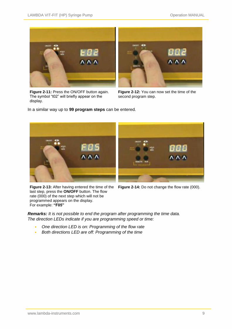
Figure 2-11: Press the ON/OFF button again. The symbol “t02” will briefly appear on the display.
Figure 2-12: You can now set the time of the
second program step.
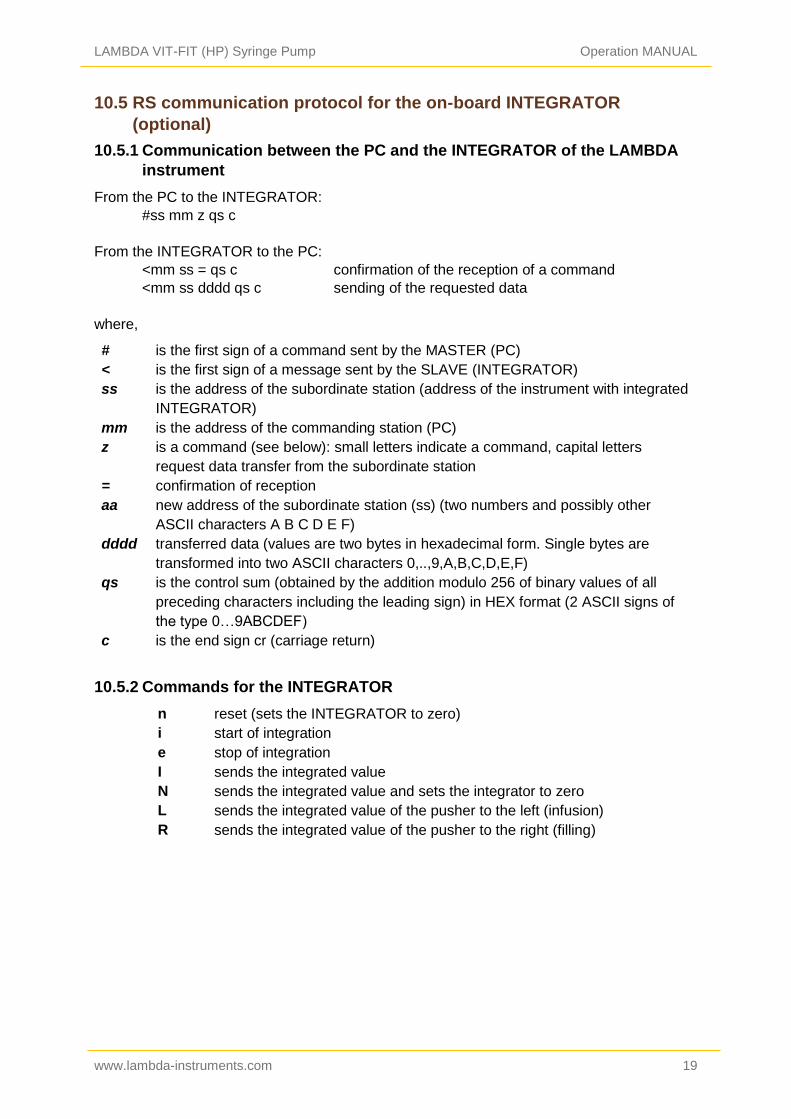
In a similar way up to 99 program steps can be entered.
Figure 2-13: After having entered the time of the last step, press the ON/OFF button. The flow rate (000) of the next step which will not be programmed appears on the display. For example: “F05”
Figure 2-14: Do not change the flow rate (000).
Remarks: It is not possible to end the program after programming the time data.
The direction LEDs indicate if you are programming speed or time:
• One direction LED is on: Programming of the flow rate
• Both directions LED are off: Programming of the time

LAMBDA VIT-FIT (HP) Syringe Pump Operation MANUAL
www.lambda-instruments.com 10
Figure 2-15: Press both REMOTE and RUN buttons simultaneously and you will see the indication “c01” on the display. This indicates that the program will be executed only once and the syringe pump will stop afterwards.
Figure 2-16: If you wish to repeat the same program 2 times, increase the cycle number to “c02” by pressing the buttons Λ Λ Λ below the display (from 0 to 99 cycles). The program can be repeated up to 99 times, indicated by “c99”. If 0 is entered for the cycle number “c00”, the program will run continuously (infinite loop).
Figure 2-17: Press the ON/OFF button again until the indication “End” appears on the display to confirm and save the program.
Figure 2-18: To START the program, press the RUN button. The RUN and ON/OFF LEDs are
on.
To stop the running program definitively, press the RUN button. The RUN and ON/OFF
LEDs are off.
It is possible to stop the pump by pressing the ON/OFF button, to change the direction and
the pusher speed during any running program step. This facilitates urgent replacement of
tubing or allows reaction in other emergency situations.
Remark: Do not forget to restore the right direction of the pusher movement and to switch
the pump on again (by pressing the ON/OFF button) after you have finished your
intervention.
The time basis in the microprocessor is not stopped during this intervention, so that the
total time of the running steps and of the whole program will not be affected. When the

LAMBDA VIT-FIT (HP) Syringe Pump Operation MANUAL
www.lambda-instruments.com 11
program step time has elapsed, the pump will automatically go on with the next program
step. Thus, the program is not modified by this emergency intervention.
It is possible to review the program by proceeding in the same way as during programming
but without modifying it.
3 REMOTE CONTROLS
3.1 ON/OFF remote control
By interlinking contacts no. 4 and 5 of the socket at the rear of the pump (see figure 71 and
section 7.2), the pump will be blocked and both direction indicating LEDs will be switched off.
The same effect can be obtained by applying a voltage from 3 to 12 V DC to contact no. 5 (at
the same time the 0 line must be connected to contact no. 3).
Remark: In some cases a reversed logic for the remote control might be desired. Please
contact us in this case.
3.2 Remote control of the pump speed
The VIT-FIT syringe pump can be controlled over the whole speed range by an external
signal (0–10 V, or as an option 0–20 or 4–20 mA). The plus pole of the signal is connected to
contact no.1, and the 0 line to contact no.3.
Press the REMOTE button on the front panel. The corresponding LED diode will light and the
display will indicate the approximate voltage of the external signal. This indication may
become unstable when no external connection is made and indicates the high sensitivity of
the electronics.
For safety reasons the voltage of the external signal must not exceed 48 V to earth!
3.3 PC control
If the instrument has been equipped with the optional RS-232 or RS-485 interface, it can be
controlled digitally, e.g. from a PC by PNet control software.
Disconnect the pump from the mains. While keeping the direction button ◄Ι► pressed
connect the pump to the mains again. The message “A” and two numbers will appear on the
display. This number from 00 to 99 is the current address of the pump. To change the

LAMBDA VIT-FIT (HP) Syringe Pump Operation MANUAL
www.lambda-instruments.com 12
address press the buttons Λ Λ Λ under the display until the desired number is obtained. To
confirm the address and save it, press the ON/OFF button.
4 OVER PRESSURE PROTECTION
The LAMBDA VIT-FIT syringe pump is equipped with a new security system, which will shut
off the motor when the pushing force in any direction exceeds admissible levels.
The message “Ovr” will appear on the display and the direction of the syringe plunger
pusher will be automatically changed from the blocked direction into the free direction.
To release the blocking, the plunger pushing arm must be moved at least shortly into the free
direction.
When the VIT-FIT syringe pump is controlled by the PNet software, press the direction button
for fast movement, i.e. pressing the button ◄Ι► during several seconds into the free
direction (indicated by the corresponding direction LED) to relieve the blocking and then fix
the problem which has provoked the overpressure.
5 RECOMMENDATIONS
If, as a consequence of tube breakage, syringe leakage or some other accident, liquid spills
in the top of the pump, disconnect the pump from the mains and clean it by removing the
liquid and rinsing it with water. The VIT-FIT syringe pump is constructed in a way, that within
certain limits the liquid should not penetrate into the interior of the pump.
Clean the pump with a damp cloth. Mild solvents like ethanol, isopropanol, alkanes are
tolerated, if the exposure is short. A Teflon (or Elox coating) covers the black surfaces and
even acetone can be used on these areas (but not on the front panel and display area).
Should you have any difficulties or questions concerning your LAMBDA VIT-FIT or VIT-FIT
HP high-pressure syringe pump, please contact our service office (support@lambda-
instruments.com).
6 FOR YOUR SAFETY
Thanks to the use of a plug-in power supply giving only a low voltage of 12 V DC the danger
of electrical shock during the use of the VIT-FIT infusion pump has been virtually eliminated,
even in the case when an electro conductive solution penetrates the infusion pump.
If the syringe pump is not used for an extended period of time, disconnect it from the mains.
A modern miniaturized switching power supply is used, which has only a negligible
consumption of electric current when the pump is not in use.

LAMBDA VIT-FIT (HP) Syringe Pump Operation MANUAL
www.lambda-instruments.com 13
7 TECHNICAL SPECIFICATIONS
7.1 General specification
Type: LAMBDA VIT-FIT / VIT-FIT HP – microprocessor-controlled programmable syringe pump (infusion / withdrawal)
Programming: up to 99 steps of speed and time
Time resolution: 0 to 999 minutes in 1 minute steps or 0 to 99.9 minutes in 0.1 minute steps: time resolution can be selected individually for each program step
Accuracy: 1%
Reproducibility: 0.2% (electronics)
Syringes: glass, plastic, metal syringes from 5 µl to over 150 ml
Flow rate: depends on the inner syringe diameter
Non-volatile memory: storage of all settings
Maximum force: VIT-FIT: 300 N (reducible by a switch to 80 N) VIT-FIT HP: 600 N (reducible by a switch to 160 N)
Motor: microprocessor controlled brushless long life BLDC motor with neodymium magnets
Transmission: efficient force transmission by a ball screw with highest mechanical load capacity of 12’000 N
Pusher travel: 120 mm
Pusher travel rate: Minimum: Maximum:
0.08 mm/min 80 mm/min
Speed control range: 0 to 999
Interface: RS-232 or RS-485 (optional)
Power supply: 95–240 V/50–60 Hz AC plug-in power supply with DC 12V/24W output; possible field operation on 12 V accumulator
Dimensions: 26.5 (W) x 12.5 (H) × 13 (D) cm
Weight: 3.2 kg
Safety: CE, meets IEC 1010/1 norm for laboratory instruments
Operation temperature: 0-40 °C
Operation humidity: 0-90% RH, not condensing
Remote control: 0-10 V; (option 0-20 or 4-20 mA)
For safety reasons the voltage of the external signal must not exceed 48 V to earth!
The syringe pump is for laboratory use only and not for human clinical use!

LAMBDA VIT-FIT (HP) Syringe Pump Operation MANUAL
www.lambda-instruments.com 14
7.2 Remote control (Inputs/outputs)
No. Colour Description
1 yellow (+) input remote speed control 0-10V *)
2 grey step signal from stepping motor (0 and 12V)
3 green earth, 0 V
4 brown + 12 V
5 white (+) input remote ON/OFF; 0V = ON, 3–12 V = OFF (this logic can be inversed on demand)
6 pink earth, ground (GND)
7 red RS 485 B (-)
8 blue RS 485 A (+) *) (zero line connected to the contact no. 3)
7.3 Input (12 V DC)
Contact No. Description
1 + 12 V DC
2 0 V
3 not connected
7.4 Output (Valves)
Contact No. Description
1 filling valve 12 V/1 A DC
2 not connected
3 + 12 V DC
4 not connected
5 delivery valve 12 V/1 A DC
6 not connected
Figure 7-1: 8-pole connector
Figure 7-2: 3-pole connector
Figure 7-3: 6-pole connector

LAMBDA VIT-FIT (HP) Syringe Pump Operation MANUAL
www.lambda-instruments.com 15
8 ACCESSORIES AND SPARE PARTS
8.1 Pump flow integrator (Art. No. 4803)
The LAMBDA VIT-FIT syringe pump and the other LAMBDA pumps are the only pumps on
the market, which allow a simple and precise integration of the amount of liquid that has
been delivered by the pump.
The electrical impulses, which move the pump motor, are registered and the RS-interface
allows the control from a PC.
In chemical or biological processes, where the pump is controlled e.g. by a pH-stat it is often
important to know, when and how much acid or base was added. This data yields
important information about the process, its kinetics and time of completion, etc.
Another use of the INTEGRATOR is for the measurement of enzyme activities (e.g.
amidases, esterases, lactamases, lipases, proteases and other enzymes).
The PUMP-FLOW INTEGRATOR can now be electronically implemented inside the VIT-FIT
and VIT-FIT HP syringe pumps and, therefore, does not require any additional valuable
laboratory bench space.
The INTEGRATOR connected to LAMBDA pumps allows new and unusual applications (e.g.
gradient making, counter flow elution, liquid chromatography, electronic burette, etc.).
8.2 PNet control software for peristaltic and syringe pumps, DOSER or
MASSFLOW (Art. No. 6600)
PNet is a PC control software for the remote
control of LAMBDA laboratory instruments
(syringe pump VIT-FIT, peristaltic pumps
PRECIFLOW, MULTIFLOW, HIFLOW,
MAXIFLOW, powder dosing instrument
DOSER and gas flow controller MASSFLOW).
The pumps are connected to the computer
through a RS-232 or RS-485 interface.
Up to 6 LAMBDA laboratory instruments and
12 INTEGRATORs can be connected and
controlled simultaneously.
If other functions are needed, you can make
contact with us (support@lambda-instru-
ments.com).
If possible, we will integrate the desired
functions in your software system, in such a
way that it conforms optimally to your
specifications.
Figure 8-1: Remote control of the VIT-FIT syringe pump with the PNet control software

LAMBDA VIT-FIT (HP) Syringe Pump Operation MANUAL
www.lambda-instruments.com 16
8.3 List of accessories and spare parts
Art. No. Accessories
4803 PUMP-FLOW INTEGRATOR (for LAMBDA pumps, DOSER and
MASSFLOW)
4810 Pump remote control (analog and digital) cable, 8 poles (open ends)
4802 Pump ON/OFF remote control cable, 2 poles (open ends)
4823 Foot switch for ON/OFF control, 8 poles
4824 Cable for inverted analog ON/OFF control, 8 poles
4830 Valve connection cable 6 poles (open ends) for VIT-FIT Syringe Pump
Interface and Control software
4822 RS232 interface (for connection of the instruments to the serial port)
4816 RS485 interface (for connection of the instruments to the serial port)
4817 RS232/485 converter
4818 Power supply for RS232/485 converter (5V/1W)
4819 RS-line connection cable (serial)
6600 PNet control software for peristaltic and syringe pumps, DOSER or
MASSFLOW
800202 Quadruple plug box (Power and RS-connection for up to 4 LAMBDA
laboratory instruments)
Spare parts
4821 Plug-in power supply (12V/24W) for HIFLOW, MAXIFLOW, VIT-FIT,
MASSFLOW
4813-b BLDC motor (HIFLOW, VIT-FIT)
4814-b Gearbox (VIT-FIT)
7010 Syringe fixing strap
9 GUARANTEE
LAMBDA provides a two-year guarantee on material and manufacturing defects, if the
instrument was used according to the operation manual.
Conditions of guarantee:
The instrument must be returned with a complete description of the defect or problem.
In order to send back the equipment for repair, you will need a returns authorization
number from LAMBDA.
The customer will send the instrument to our service office.
Damage or loss of items during transport will not be compensated for by LAMBDA.
Failure to fulfil these requirements will disqualify the customer from compensation.
Serial Number: _____________________________
Guarantee from: ____________________________

LAMBDA VIT-FIT (HP) Syringe Pump Operation MANUAL
www.lambda-instruments.com 17
10 APPENDIX
10.1 RS communication protocol for LAMBDA VIT-FIT, PRECIFLOW,
MULTIFLOW, HIFLOW and MAXIFLOW pumps
10.1.1 Format of data sent by the PC to the pump and back
Data sent by the PC: #ss mm a ddd qs c
Data sent back by the pump: <mm ss a ddd qs c
where,
# is the first sign of a command sent by PC
< is the first sign of a message sent by pump
ss is the address of the pump
mm is the address of the PC
a is the command for the movement direction:
r movement of the pusher to the left (infusion)
l movement of the pusher to the right (filling)
ddd is the speed of rotation (3 ASCII numbers from 0 to 9; sent from the highest order
digit to the lowest order digit)
qs is the control sum in HEX format (2 ASCII signs of the type 0…9ABCDEF)
c is the end sign cr (carriage return) The pump will fulfil the task and block any
manual command on the pump front panel.
10.1.2 Commands not containing data
# ss mm g qs c activates the local command of the pump
# ss mm s qs c the pump is stopped
# ss mm G qs c to send pump data to the PC
10.1.3 Checksum control
The PC sends: #0201r123EEcr
The control sum (checksum) qs is made in the following way (only the last byte (2 ASCII
characters of the type 0…9ABCDEF) is taken):
# 0 2 0 1 r 1 2 3 EE (last byte)
cr
23h +30h +32h +30h +31h +72h +31h +32h +33h =1EEh 0Dh
10.1.4 Format of the data transmission
Speed: 2400 Bd (Baud)
8 data bits, odd parity, 1 stop bit

LAMBDA VIT-FIT (HP) Syringe Pump Operation MANUAL
www.lambda-instruments.com 18
10.2 Examples
Address of the PC: 01
Address of the pump: 02
The PC sends: #0201r123EEcr
The pump will move the pusher to the left (infusion) at the speed of 123.
The PC sends: #0201G2Dcr
The answer of the pump: <0102r12307cr
The PC sends: #0201l123E8cr
The pump will move the pusher to the right (filling) at the speed of 123.
The PC sends: #0201s59cr
The pump stops.
The PC sends: #0201g4Dcr
The pump will go to the local command (pump front panel is activated).
10.3 How to set the Pump address?
To look up/modify the instrument address, disconnect the pump from the mains.
While keeping the direction button ◄Ι► pressed connect the pump to the mains again. The
message “A” and two numbers will appear on the display. This number from 00 to 99 is the
current address of the pump.
To change the address press the buttons Λ Λ Λ under the display until the desired number is
obtained. To confirm the address and save it, press the ON/OFF button.
10.4 RS-connection scheme
The 8-pole DIN connector “REMOTE” is used for the remote control and RS-485 connection.
When the optional RS-485 interface is available the pins are used as follows:
No. Colour Description
1 yellow (+) input remote speed control 0-10V *)
2 grey step signal from stepping motor (0 and 12V)
3 green earth, 0 V
4 brown + 12 V
5 white (+) input remote ON/OFF; 0V = ON, 3–12 V = OFF (this logic can be inversed on demand)
6 pink earth, ground (GND)
7 red RS 485 B (-)
8 blue RS 485 A (+) *) (zero line connected to the contact no. 3)
Figure 10-1: 8 pole connector
LAMBDA VIT-FIT (HP) Syringe Pump Operation MANUAL
www.lambda-instruments.com 19
10.5 RS communication protocol for the on-board INTEGRATOR
(optional)
10.5.1 Communication between the PC and the INTEGRATOR of the LAMBDA
instrument
From the PC to the INTEGRATOR:
#ss mm z qs c
From the INTEGRATOR to the PC:
<mm ss = qs c confirmation of the reception of a command
<mm ss dddd qs c sending of the requested data
where,
# is the first sign of a command sent by the MASTER (PC)
< is the first sign of a message sent by the SLAVE (INTEGRATOR)
ss is the address of the subordinate station (address of the instrument with integrated
INTEGRATOR)
mm is the address of the commanding station (PC)
z is a command (see below): small letters indicate a command, capital letters
request data transfer from the subordinate station
= confirmation of reception
aa new address of the subordinate station (ss) (two numbers and possibly other
ASCII characters A B C D E F)
dddd transferred data (values are two bytes in hexadecimal form. Single bytes are
transformed into two ASCII characters 0,..,9,A,B,C,D,E,F)
qs is the control sum (obtained by the addition modulo 256 of binary values of all
preceding characters including the leading sign) in HEX format (2 ASCII signs of
the type 0…9ABCDEF)
c is the end sign cr (carriage return)
10.5.2 Commands for the INTEGRATOR
n reset (sets the INTEGRATOR to zero)
i start of integration
e stop of integration
I sends the integrated value
N sends the integrated value and sets the integrator to zero
L sends the integrated value of the pusher to the left (infusion)
R sends the integrated value of the pusher to the right (filling)
LAMBDA VIT-FIT (HP) Syringe Pump Operation MANUAL
www.lambda-instruments.com 20
10.5.3 Examples
Address of the PC: 01
Address of the instrument with on-board INTEGRATOR: 02
The PC sends: #0201I2Fcr
The control sum (checksum) qs is made in the following way (only the last byte (2 ASCII
characters of the type 0…9ABCDEF) is taken):
# 0 2 0 1 I 2F (last byte) cr
23h +30h +32h +30h +31h +49h =12Fh 0Dh
The PC sends: #0201i4Fcr
i.e. in hexadecimal form: 23h 30h 32h 30h 31h 69h 34h 46h 0Dh
This means: For a subordinate station (SLAVE) with address 02 from commanding station
(MASTER) with address 01
Start of integration
The control sum is 14Fh (last byte: 4F); end of message cr (carriage return)
The INTEGRATOR answers: <0102=3Ccr
The PC sends: #0201N34cr
The INTEGRATOR answers: <0102N03C225cr (integrated value is 03C2h)
and resets to zero
The PC sends: #0201e4Bcr
The integration will be stopped and the command will be confirmed.
The INTEGRATOR answers: <0102=3Ccr
LAMBDA Laboratory Instruments Sihlbruggstrasse 105 CH-6340 Baar SWITZERLAND – EUROPE Tel.: +41 444 50 20 71 Fax: +41 444 50 20 72
LAMBDA CZ s.r.o. Lozíbky 1 CZ-61400 Brno CZECH REPUBLIC – EUROPE Hotline: +420 603 274 677
E-mail: [email protected] Web: www.lambda-instruments.com
www.syringepump.info