operation manual diesel tech ds2 - ftf · operation manual diesel tech ds2 ver. 2010.2. ... ds2...
TRANSCRIPT

Operation Manual
Diesel Tech DS2
ver. 2010.2


DS2 Series
Operating Manual i
Contents
Chapter 1 “Introduction”__________________________________ 1-1
Equipment checklist____________________________________________ 1-2
Options _____________________________________________________ 1-3
Chapter 2 “Product Tour” _________________________________ 2-1
Front View ___________________________________________________ 2-3
Side View ____________________________________________________ 2-5
Rear View____________________________________________________ 2-7
Rear Panel symbols ____________________________________________ 2-9
Serial Tag ___________________________________________________ 2-10
Chapter 3 “Getting Started” _______________________________ 3-1
Unpacking and setting up _______________________________________ 3-3
Connecting the AC power _______________________________________ 3-4
DS2 Unit ___________________________________________________ 3-4
Injector Ultrasonic Device [optional / DS2-X1] ______________________ 3-5
Connecting the Pneumatics ______________________________________ 3-6
Starting up for the first time ____________________________________ 3-10
Powering down the system _____________________________________ 3-12
Chapter 4 “Menu Tour” ___________________________________ 4-1
Control Panel _________________________________________________ 4-3
Startup Screen ________________________________________________ 4-5
Settings Screen _______________________________________________ 4-6
Injector Selection Screens _______________________________________ 4-8
Test / MACC Screens __________________________________________ 4-12
Chapter 5 “Prepare the DS2” ______________________________ 5-1
Fluids and Filters ______________________________________________ 5-2

DS2 Series
ii Operating Manual
Testing Fluid & Filter __________________________________________ 5-3
Cleaning Fluid & Filter [DS2-X1 only] _____________________________ 5-5
Chapter 6 “Operation Basics” ______________________________ 6-1
Injector Ultrasonic Cleaner ______________________________________ 6-3
Injector Mounting _____________________________________________ 6-5
Injector Clamp ________________________________________________ 6-5
Injector Spray Chamber Clamping Position and connections ____________ 6-8
Injector iVM Clamping Position and connections _____________________ 6-9
Sample Procedure on Testing Injectors ____________________________ 6-10
1: Select the injector ______________________________________ 6-10
2: OHM Test_____________________________________________ 6-10
3: Spray Test ____________________________________________ 6-11
4: iVM (Injector Volume Metering) ___________________________ 6-11
5: CANCEL/STOP button in each test screen ____________________ 6-12
Injector MACC Clamping Position and connections___________________ 6-13
MACC (Cleaning Injectors internally) [DS2-X1 only] __________________ 6-14
Chapter 7 “Troubleshooting” ______________________________ 7-1
Appendix A “Specifications” _______________________________A-1
Appendix B “Adapters and Connectors” _____________________ B-1
Appendix C “Connectivity/Illustrations” _____________________ C-1

DS2 Series
Operating Manual iii
Figures Figure 2-i ________________________________________________________________________ 2-4
Figure 2-ii _______________________________________________________________________ 2-6
Figure 2-iii _______________________________________________________________________ 2-8
Figure 3-i ________________________________________________________________________ 3-4
Figure 3-ii _______________________________________________________________________ 3-7
Figure 3-iii _______________________________________________________________________ 3-8
Figure 3-iv _______________________________________________________________________ 3-9
Figure 3-v ______________________________________________________________________ 3-10
Figure 3-vi ______________________________________________________________________ 3-11
Figure 4-i ________________________________________________________________________ 4-3
Figure 4-ii _______________________________________________________________________ 4-5
Figure 4-iii _______________________________________________________________________ 4-6
Figure 4-iv _______________________________________________________________________ 4-8
Figure 4-v _______________________________________________________________________ 4-9
Figure 4-vi ______________________________________________________________________ 4-10
Figure 4-vii _____________________________________________________________________ 4-10
Figure 4-viii _____________________________________________________________________ 4-11
Figure 4-ix ______________________________________________________________________ 4-11
Figure 4-x ______________________________________________________________________ 4-12
Figure 4-xi ______________________________________________________________________ 4-13
Figure 5-i ________________________________________________________________________ 5-2
Figure 5-ii _______________________________________________________________________ 5-5
Figure 5-iii _______________________________________________________________________ 5-7
Figure 6-i ________________________________________________________________________ 6-3
Figure 6-ii _______________________________________________________________________ 6-4
Figure 6-iii _______________________________________________________________________ 6-6
Figure 6-iv _______________________________________________________________________ 6-7
Figure 6-v _______________________________________________________________________ 6-8
Figure 6-vi _______________________________________________________________________ 6-9
Figure 6-vii _____________________________________________________________________ 6-13

DS2 Series
iv Operating Manual
Copyright The distribution and sales of the product are intended for use by the
original purchaser. This document may not, in whole or part, be
copied, photocopied, reproduced, translated or reduced to any
electronic medium of machine-readable form without prior consent in
writing from Carbon Zapp.
The information in this document is subject to change without notice.
Company Information
CARBON ZAPP
8 Alimou Ave. - Alimos – 17455 - Athens -
GREECE
Tel.: + (30)210-99.28.304 / Fax: + (30)210-
99.28.655
E-mail: [email protected] /
URL: www.CarbonZapp.com

DS2 Series
Operating Manual v
Warranty 2 –YEAR DS2 LIMITED WARRANTY
“Carbon Zapp” company manufactures its equipment from new parts
and components that are in accordance with industry-standard
practices. Carbon Zapp warrants that the equipment it manufactures
will be free of defects in materials and workmanship.
The warranty terms are 2 years, beginning on the date of the Carbon
Zapp invoice in accordance with the following described:
This warranty does not cover damage due to external causes,
including accident, abuse, misuse, scratches on external components
or surfaces, problems with electrical power supply, servicing not
authorized by Carbon Zapp, usage not in accordance with machine’s
operating manual, failure to perform required preventative
maintenance, failure to change the testing calibration oil fluid (and
cleaning detergent) when indicated by machine, failure to change the
testing (and cleaning) fluid filter when indicated by machine, to permit
machines fluid pump to sit or operate without fluid in it, usage of
improper testing or cleaning fluid in the machine, usage of improper
ultrasonic cleaning fluid in the ultrasonic bath, usage of ultrasonic
fluid instead of testing fluid or the opposite, usage of cleaning solvents
and chemicals not provided or indicated/approved by Carbon Zapp,
use of parts and components not supplied or approved by Carbon
Zapp.
Note: Failure to clean injectors with Carbon Zapp’s ultrasonic device
(Optional) before any test is performed on the DS2 test bench will
void the warranty of the machine. If the iVM hydraulic system
operation and graduated tube indications are is out of specification or
accuracy due to dirt (verified), the machine’s warranty will not be
liable
Carbon Zapp will repair or replace parts and components returned to
manufacturer’s facility. To request warranty service, contact Carbon
DS2 Series
vi Operating Manual
Zapp within the warranty period. If warranty service is required, you
must ship the defective part or component in their original or
equivalent packaging, prepay shipping charges, and insure, or accept
the risk of loss or damage during shipment. Carbon Zapp will return
the repaired or replacement part or component freight prepaid. If
Carbon Zapp repairs or replaces a part or component, its warranty
term is Not Extended.
Carbon Zapp does not accept liability beyond the remedies set forth in
this warranty statement or liability for incidental or consequential
damages.
Machine serial number: _____________________________________
Signed by: Technical Department:_____________________________

DS2 Series
Operating Manual vii
Date: _____/_____/_________


Introduction
Operating Manual 1-1
“Introducti
on”
Through the years, there has been an excess demand in Pollution
Reduction, Fuel Economy and Enhanced Performance for Consumer
Engines. Engine Manufacturers have gone a long way, since
conventional Diesel systems, to reach today at the revolutionary
approach of Electronically Controlled Injection systems, thereafter
called Common-Rail (CRDI). With this approach they have successfully
reduced emissions and gained fuel economy and performance
through accurate injection of fuel.
The Electronically Controlled Diesel Fuel Injectors, although accurate,
produce chronicle defects. Through time numerous faults may occur,
such as fuel residue built-up at nozzle and back-leak valve (pressure-
relief valve), electrical coil or Piezo crystal failure and injector pathway
blockage. These faults in turn, produce an undesired effect which
causes increase in emissions and fuel consumption, unstable engine
operation and loss of engine performance.
Carbon Zapp, a leading manufacturer in Automotive Injection Service
Solutions, offers the DS2 Unit for the treatment of all Common-Rail
Injectors presently used, and provides upgradeability of the machine
for Future Injectors.
DS2 Series
1-2 Operating Manual
Equipment checklist
Carefully unpack the machine and its components. Save the box
and packaging materials for future use.
Check if you have all the following items:
- DS2 Series Common-Rail Testing and Servicing Unit
- Injector Ultrasonic Device [100/240 VAC] with: [DS2-X1]
o Operating Manual
o AC Power Cord[100/240 VAC]
o Injector Holder
- AC [100/240 VAC] Power Cord, for DS2 Series Unit
- Calibrating Oil (Shell V-OEL 1404 or equivalent), prefilled ½
tank start-up consumable for Testing injectors
- 4 liter Calibration Oil, start-up consumable for DS2 Testing
injectors
- 4 liter Ultrasonic Cleaning Solvent, start-up consumable for
Ultrasonic Cleaning injectors
- 2 liter Cleaning Detergent, start-up consumable for MACC
Cleaning of injectors [DS2-X1 only]
- Calibration Oil/Fluid Funnel – Large
- Cleaning detergent Funnel (MACC) - Small with extension for
quick coupler [C] [DS2-X1 only]
- Adapters and Accessories Kit for Testing Injectors [look at
Appendix B]
- Adapters and Accessories Kit for Cleaning Injectors [look at
Appendix B] [DS2-X1 only]
- Piezo Injector Back-Leak Regulator Kit "PIR"
[Optional]
- Operating Manual and Quality Control Certificate

Introduction
Operating Manual 1-3
Options
There are a number of options to make the DS2 unit even more
powerful and universal in diagnosing and servicing the Diesel
Injectors. The following options are available:
Code Description Hardware
Needed Models
MACC Upgrade Kit YES DS2-X0
CRIN
ADAPTERS
Industrial Common-Rail
Injector Adapters
(Request availability list
from your local dealer)
YES DS2-XX
PS80 Portable stand DS2 YES DS2-XX
PIR
Piezo Injector Back-Leak
Regulator Kit "PIR" YES DS2-XX

Product Tour
Operating Manual 2-1
“Product T
our”
This chapter provides an overview of the DS2 exterior views and
connections. It covers the following topics:
- Front View
- Side View
- Rear View
- Rear View Symbols
- Serial Tag
DS2 Series
2-2 Operating Manual
A new user should be familiar with all the views and connections
in this chapter.

Product Tour
Operating Manual 2-3
Front View
a. Injector Clamp
b. Injector Spray Chamber fumes extractor
c. Injector Spray Chamber
d. Unit adjustable support pads
e. PIR Pressure Regulator
f. PIR Pressure Gauge
g. Control Panel
h. High Pressure Regulator
i. LCD SCREEN
j. Front Connections
a. [ih] Injector Harness connector
b. iVM
i. PI[R] Testing Return Connector (for PIR use)
ii. [R] Testing Return Connector
iii. [D] iVM Testing Discharge Connector
c. MACC
i. [C] Cleaning MACC Discharge and Return Port
k. iVM lit Volumetric Tubes
l. High Pressure clear protective cover opening switch
m. Clear Protective cover

DS2 Series
2-4 Operating Manual
Figure 2-i
m
e f g
c
a
h
k b
d
i
j
l

Product Tour
Operating Manual 2-5
Side View
a. Left, Side Panel
b. Right, Side Panel
c. Testing Calibration OIL level indicator
d. Cleaning (MACC) detergent level indicators

DS2 Series
2-6 Operating Manual
Figure 2-ii
a
c
d
b

Product Tour
Operating Manual 2-7
Rear View
a. Rear, Top Panel
b. Serial Tag
c. Spray Chamber fumes extractor output
d. Regulated and filtered compressed air input
e. HP Pump air exhaust port
f. Testing Calibration OIL drain valve
g. Testing Calibration OIL Filter
h. Cleaning (MACC) Filter
i. Cleaning (MACC) drain valve
j. Rear, Bottom Panel
k. Mains, Rear ON/OFF switch
m. UIS Attachment unit connections (x.1 / x.2)

DS2 Series
2-8 Operating Manual
Figure 2-iii
h i g f
m
a
k
j
d
c
b
e

Product Tour
Operating Manual 2-9
Rear Panel symbols
: This symbol is used to denote the Air Input connection.
Please consult Appendix A for specifications. Beneath it is a Water
Trap/Filter/Regulator (Figure 2-iii-[d]).
: This symbol is used to denote the Fumes Output (Spray
Chamber Extractor) Connection. DO NOT connect the compressed air
line here. Beneath it, is a Fumes - liquid Trap/collector / Separator
(Figure 2-iii-[c]).
: These symbols denote that in the left part of the
machine the hydraulics are used for the Cleaning (MACC) and in the
right part of the machine the hydraulics are used for Testing
(Calibration Oil). The filters and drain valves are considered hydraulics
in this case.
DS2 Series
2-10 Operating Manual
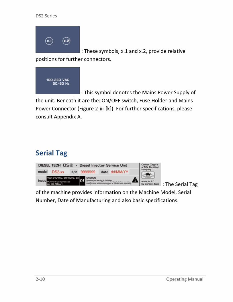
: These symbols, x.1 and x.2, provide relative
positions for further connectors.
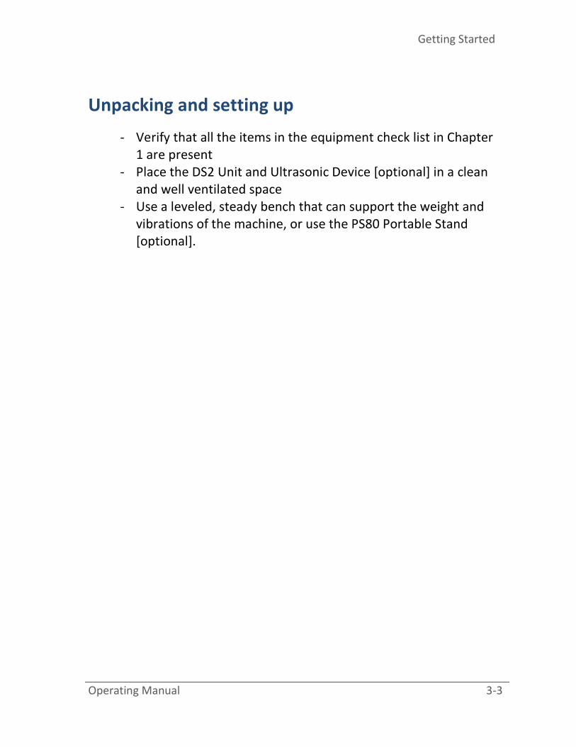
: This symbol denotes the Mains Power Supply of
the unit. Beneath it are the: ON/OFF switch, Fuse Holder and Mains
Power Connector (Figure 2-iii-[k]). For further specifications, please
consult Appendix A.
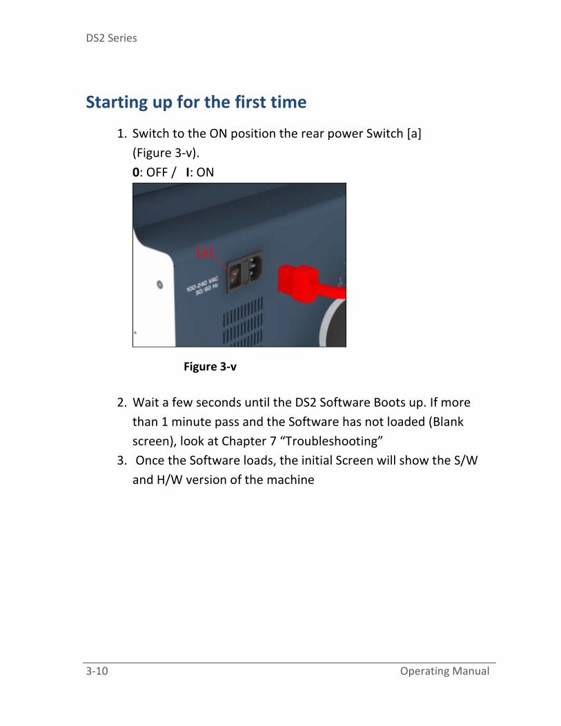
Serial Tag
: The Serial Tag
of the machine provides information on the Machine Model, Serial
Number, Date of Manufacturing and also basic specifications.

Getting Started
Operating Manual 3-1
“Getting St
arted”
This chapter provides basic information to start using the DS2
unit and covers the following topics:
[info]
All users should be familiar with diesel systems and should
always wear protective goggles and gloves.
- Unpacking and setting up
- Connecting the AC power
- Connecting the Pneumatics
- Starting up for the first time
- Powering down the system

DS2 Series
3-2 Operating Manual
A new user should follow the steps in each section of this
chapter in order to operate the machine.
Getting Started
Operating Manual 3-3
Unpacking and setting up
- Verify that all the items in the equipment check list in Chapter
1 are present
- Place the DS2 Unit and Ultrasonic Device [optional] in a clean
and well ventilated space
- Use a leveled, steady bench that can support the weight and
vibrations of the machine, or use the PS80 Portable Stand
[optional].

DS2 Series
3-4 Operating Manual
Connecting the AC power
DS2 Unit
Verify that the rear ON/OFF Power Switch is in the OFF position.
1. Connect one end of the AC power cord [a] to the rear power
socket of the machine [b] (Figure 3-i)
2. Connect the other end of the AC Power cord to any grounded
100/240 VAC, 50/60 Hz power source (live wall outlet)
Figure 3-i
[a] [b]

Getting Started
Operating Manual 3-5
Injector Ultrasonic Device [optional / DS2-X1]
1. Connect one end of the AC power cord to the rear power
socket of the device
2. Connect the other end of the AC Power cord to any grounded
100/240 VAC, 50/60 Hz power source (live wall outlet),
depending on the Ultrasonic device specifications.
[info]
Please consult the accompanying Ultrasonic device Operating
Manual.

DS2 Series
3-6 Operating Manual
Connecting the Pneumatics
[info]
- Always use a Water Trap/Filter/Regulator to connect the Air
Supply to the machine, even if the Shop Air Compressor has a
dehumidifier installed.
- Always use the nearest route to the Shop Air Compressor and
avoid Air Hose bottlenecks, in order to achieve maximum Air
Pressure and Air Flow. Follow the specifications in
Appendix A.
- The DS2 units are equipped with a standard Water Trap.
Always regulate the compressed air input according to the
specifications in Appendix A, or on the Serial Tag of the
machine.
1. Use a hose fitting [a] (not provided) to connect the Water Trap /
Regulator to the hose that leads to the Shop Air Compressor
(Figure 3-ii)

Getting Started
Operating Manual 3-7
Figure 3-ii
2. [Optional] Disconnect the Fumes Extractor Exhaust Port
muffler/filter [b] (Figure 3-iii) and connect a large diameter hose
in order to reduce fumes and noise.
[info]
- Vacuum performance issues may occur by installing a hose
instead of the muffler.
[a]

DS2 Series
3-8 Operating Manual
Figure 3-iii
[b]

Getting Started
Operating Manual 3-9
[important]
- A periodic emptying of the vacuum collector is needed
(Figure 3-iv).
Figure 3-iv
DS2 Series
3-10 Operating Manual
Starting up for the first time
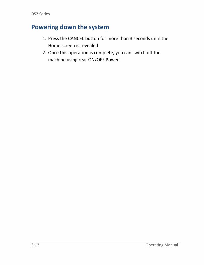
1. Switch to the ON position the rear power Switch [a]
(Figure 3-v).
0: OFF / I: ON
Figure 3-v
2. Wait a few seconds until the DS2 Software Boots up. If more
than 1 minute pass and the Software has not loaded (Blank
screen), look at Chapter 7 “Troubleshooting”
3. Once the Software loads, the initial Screen will show the S/W
and H/W version of the machine
[a]

Getting Started
Operating Manual 3-11
Figure 3-vi
4. By Pressing the ENTER button once the unit is ready to
operate
5. Look in Chapter 4 “Menu Tour” for further information on
software navigation.
[important]
- Always wait at least 15 seconds when switching on the unit
again (after a power down)
DIESEL TECH DS2
SW:1.1 / HW:20
[ENTER] to Begin
[F] for Settings Menu
DS2 Series
3-12 Operating Manual
Powering down the system
1. Press the CANCEL button for more than 3 seconds until the
Home screen is revealed
2. Once this operation is complete, you can switch off the
machine using rear ON/OFF Power.

HMI Menu Tour
Operating Manual 4-1
“Menu To
ur”
This chapter provides useful information on the DS2 Menu. It
covers the following topics:
- Control Panel
- Basic Screens
o Start-up Screen
o Settings Screen
o Injector selection Screens
o Test / MACC Screens

DS2 Series
4-2 Operating Manual
A new user should preview all the screens in this chapter prior to
operating the DS2 unit.
HMI Menu Tour
Operating Manual 4-3
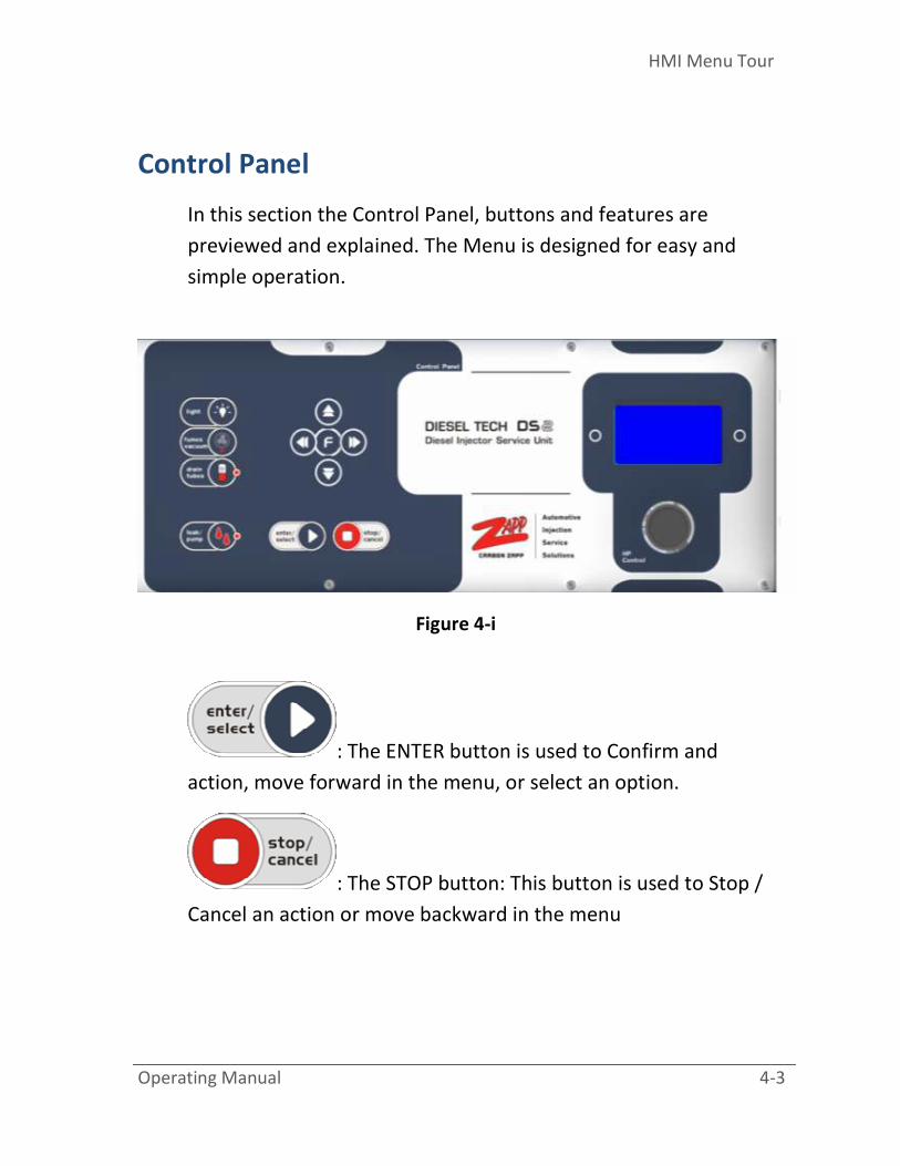
Control Panel
In this section the Control Panel, buttons and features are
previewed and explained. The Menu is designed for easy and
simple operation.
Figure 4-i
: The ENTER button is used to Confirm and
action, move forward in the menu, or select an option.
: The STOP button: This button is used to Stop /
Cancel an action or move backward in the menu
DS2 Series
4-4 Operating Manual
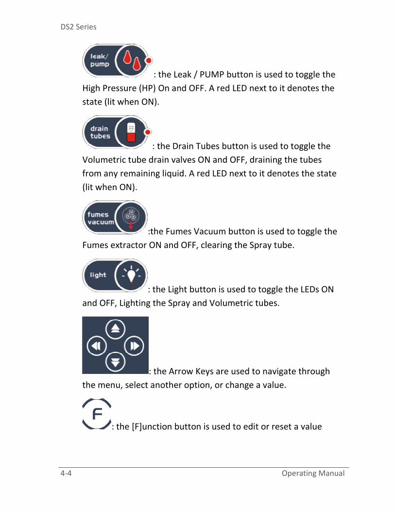
: the Leak / PUMP button is used to toggle the
High Pressure (HP) On and OFF. A red LED next to it denotes the
state (lit when ON).
: the Drain Tubes button is used to toggle the
Volumetric tube drain valves ON and OFF, draining the tubes
from any remaining liquid. A red LED next to it denotes the state
(lit when ON).
:the Fumes Vacuum button is used to toggle the
Fumes extractor ON and OFF, clearing the Spray tube.
: the Light button is used to toggle the LEDs ON
and OFF, Lighting the Spray and Volumetric tubes.
: the Arrow Keys are used to navigate through
the menu, select another option, or change a value.
: the [F]unction button is used to edit or reset a value

HMI Menu Tour
Operating Manual 4-5
Startup Screen
This screen is shown once the DS2 software loads. Information
such as Software (S/W) and Hardware (H/W) versions are shown
here. The DS2 is now ready for operation. Press the ACCEPT
button to continue.
[info]
- If the Startup Screen loads and after pressing Accept Button
there is no H/W or S/W version displayed, consult Chapter 7
“Troubleshooting”.
Figure 4-ii
DIESEL TECH DS2
SW:1.1 / HW:20
[ENTER] to Begin
[F] for Settings Menu
DS2 Series
4-6 Operating Manual
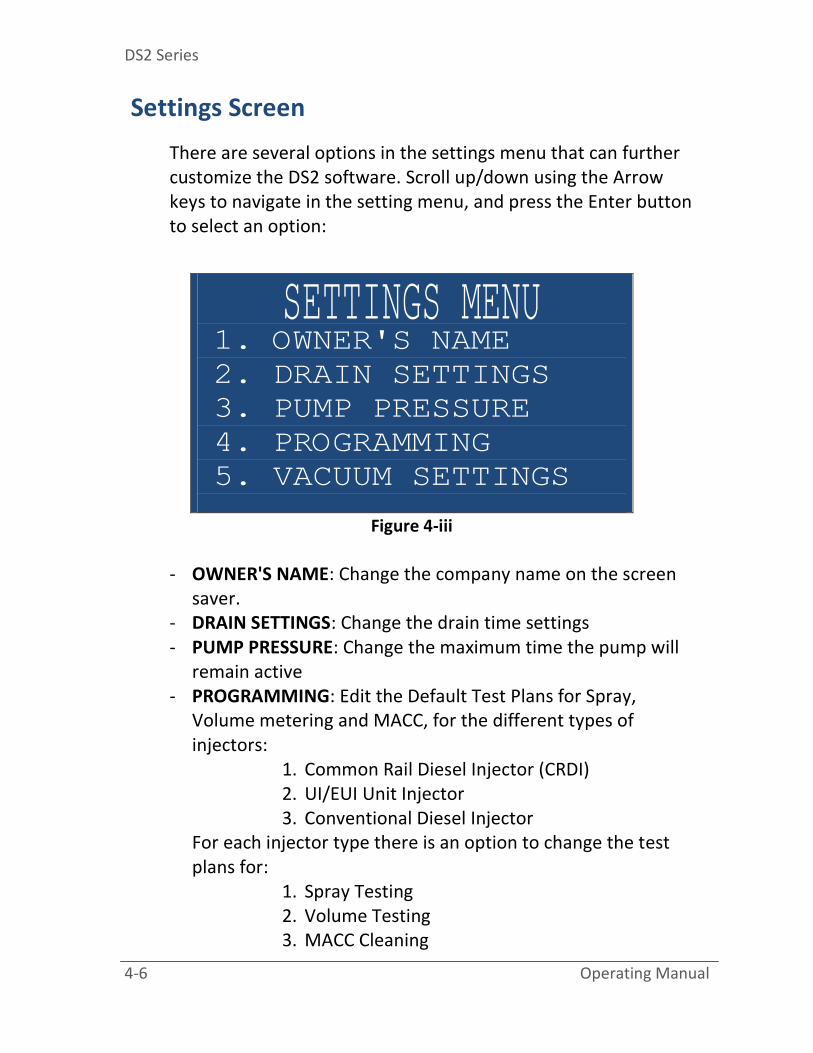
Settings Screen
There are several options in the settings menu that can further
customize the DS2 software. Scroll up/down using the Arrow
keys to navigate in the setting menu, and press the Enter button
to select an option:
Figure 4-iii
- OWNER'S NAME: Change the company name on the screen
saver.
- DRAIN SETTINGS: Change the drain time settings
- PUMP PRESSURE: Change the maximum time the pump will
remain active
- PROGRAMMING: Edit the Default Test Plans for Spray,
Volume metering and MACC, for the different types of
injectors:
1. Common Rail Diesel Injector (CRDI)
2. UI/EUI Unit Injector
3. Conventional Diesel Injector
For each injector type there is an option to change the test
plans for:
1. Spray Testing
2. Volume Testing
3. MACC Cleaning
SETTINGS MENU 1. OWNER'S NAME
2. DRAIN SETTINGS
3. PUMP PRESSURE
4. PROGRAMMING
5. VACUUM SETTINGS
HMI Menu Tour
Operating Manual 4-7
For each option, there are 4 different test plans, composed of
STRK, milliseconds, time of test and Single or Multi injection
operation. Each test plan can be edited by pressing the
[F]unction key and using the arrow keys.
- HEATING SETTINGS: Not used on this version
- VACUUM SETTINGS: Change the vacuum time settings
- LIGHT SETTINGS: Change the LED time settings
- FILTERS/FLUID Reset: In these options the Filter and Fluid life
span can be viewed (in hours) for the Cleaning (MACC) Filter
and fluid. When the Life of the filter/fluid is over (equals to
zero) a pop-up message will appear every time in the Home
Screen informing that the filter/fluid needs to be changed. To
RESET the TIME, press the [F]unction key for more than 3
seconds. More information regarding fluid and filter
specification can be found Appendix A.
- INJECTOR TYPE NAME: Change the names of the customized
Injector brands
- LANGUAGE: Select one of the available operation languages
- LOAD DEFAULTS: Reset the Test plans, Injectors and all other
parameterized data on the board, to factory defaults
- MULTI SHOT SETTINGS: Edit the multi shot settings, Pilot and
Post Pulse and Dwell time in milliseconds
- INSTRUCTIONS: Show or hide instructions before each test.
[important]
- Every time the Testing filter is replaced, it is mandatory also
to replace the screen filters (30-88) in the D and R adapters a
shown in Appendix C.

DS2 Series
4-8 Operating Manual
Injector Selection Screens
The DS2 unit can operate all types of diesel injectors (depending
on the options installed). Before a test or a cleaning procedure in
started, the injector selection process must be completed.
Below is the basic screen to define the injector selection process:
Choose between CRDI, UIS or Mechanical injectors:
Figure 4-iv
SELECT INJECTOR TYPE 1.Common-Rail Diesel
Injector (CRDI)
2.UI/EUI
Unit Injectors
3.Conventional Diesel
Injector(Mechanical)

HMI Menu Tour
Operating Manual 4-9
Choose between COIL (Solenoid / older), PIEZO (Newer)
actuation. An easy way to distinguish if an injector is coil or
piezo, is to perform an OHM TEST, if the injector has OHM, most
likely it is a coil injector:
Figure 4-v
The Injector Harness is used to provide the injector with power
while operating Electrical Diesel Injectors. Some Injectors have a
PLUS (+) sign engraved on the connection fitting in order to
denote how to correctly apply voltage. The machine harness
connectors also denote the PLUS (+) sign with a RED Dot. The
user should always connect the Plus (+) side of the connector to
the Plus (+) side of the injector, see Figure 4-vi.
[info]
The PIEZO Diesel Injectors must at all times use the correct
polarity. Often the PLUS (+) is not denoted, therefore the user
should always consult the manufacture’s or the automobile’s
service manual. For example, look at Figure 4-vii.(a) to see the
SELECT COMM.RAIL TYPE 1. COIL Common-Rail
(STANDARD)
2. PIEZO Common-Rail
(NEWER)

DS2 Series
4-10 Operating Manual
most common PLUS (+) polarity for BOSCH 115, 116 and 117
and Figure 4-vii.(b) for SIEMENS Piezo Injectors.
If you accidentally connect the Polarity wrong, the injector will
sound like it is operating, but it will not spray or discharge
volume correctly.
Figure 4-vi
Figure 4-vii
(a)
(b)

HMI Menu Tour
Operating Manual 4-11
Choose the brand of the injector:
Figure 4-viii
Choose a profile of the injector. The GENERIC profile should be
used for new users:
Figure 4-ix
SELECT MANUFACTURER 1. BOSCH
2. SIEMENS
3. DELPHI
4. DENSO
5. OTHER.1
6. OTHER.2
BOSCH -COIL 1. GENERIC
2. TYPE.B
3. TYPE.C
4. OTHER
[F] for properties
DS2 Series
4-12 Operating Manual
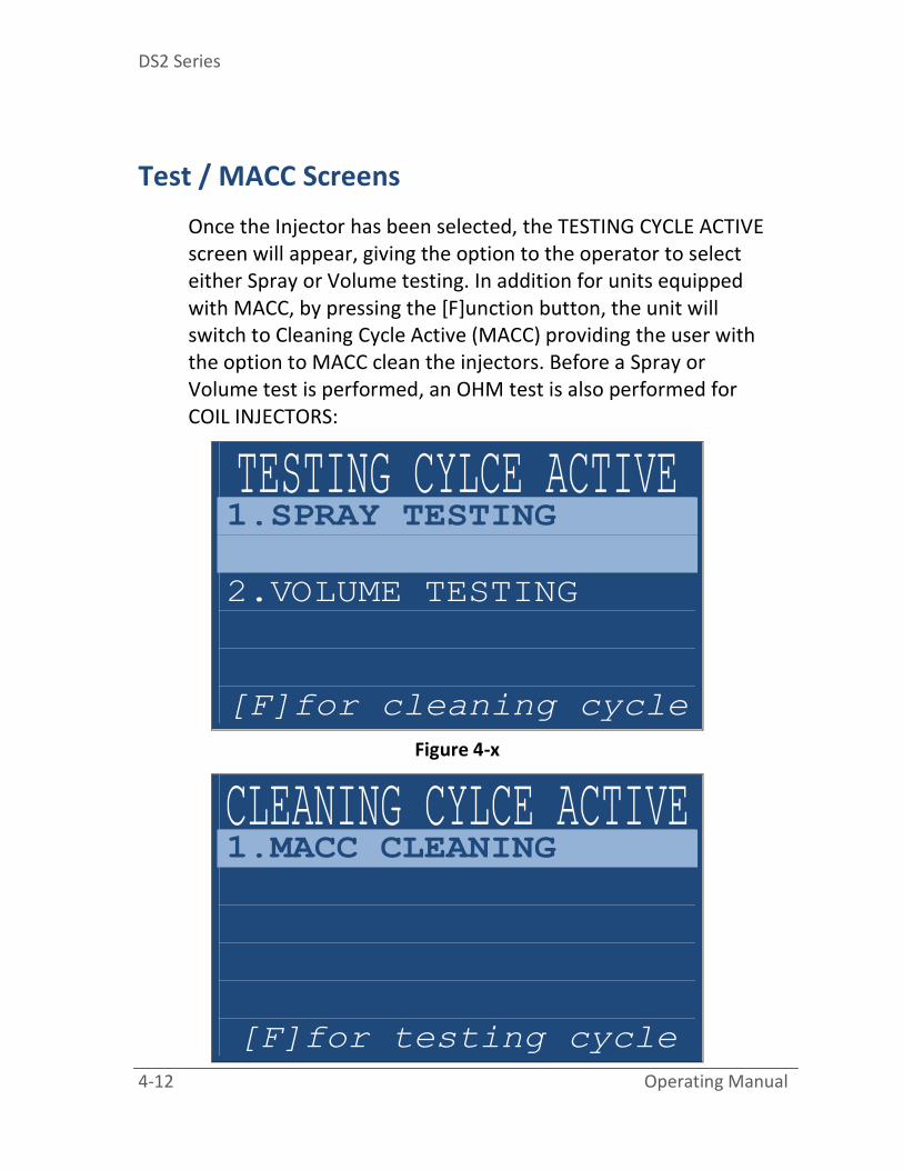
Test / MACC Screens
Once the Injector has been selected, the TESTING CYCLE ACTIVE
screen will appear, giving the option to the operator to select
either Spray or Volume testing. In addition for units equipped
with MACC, by pressing the [F]unction button, the unit will
switch to Cleaning Cycle Active (MACC) providing the user with
the option to MACC clean the injectors. Before a Spray or
Volume test is performed, an OHM test is also performed for
COIL INJECTORS:
Figure 4-x
TESTING CYLCE ACTIVE 1.SPRAY TESTING
2.VOLUME TESTING
[F]for cleaning cycle
CLEANING CYLCE ACTIVE 1.MACC CLEANING
[F]for testing cycle

HMI Menu Tour
Operating Manual 4-13
Figure 4-xi


Prepare the DS2
Operating Manual 5-1
“Prepare t
he DS2”
This chapter provides useful information on preparing the DS2
unit for the initial operation. It covers the following topics:
- Fluids and Filters
o Testing Fluid & Filter
o Cleaning Fluid & Filter
DS2 Series
5-2 Operating Manual
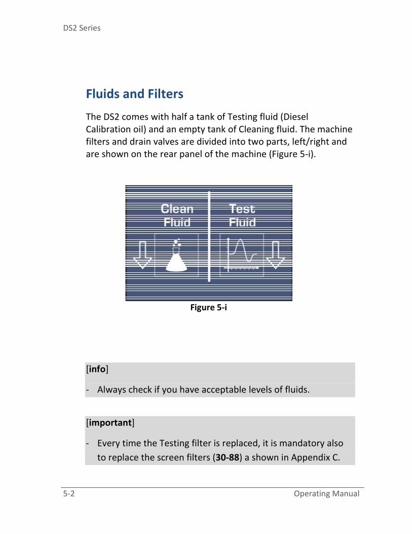
Fluids and Filters
The DS2 comes with half a tank of Testing fluid (Diesel
Calibration oil) and an empty tank of Cleaning fluid. The machine
filters and drain valves are divided into two parts, left/right and
are shown on the rear panel of the machine (Figure 5-i).
Figure 5-i
[info]
- Always check if you have acceptable levels of fluids.
[important]
- Every time the Testing filter is replaced, it is mandatory also
to replace the screen filters (30-88) a shown in Appendix C.
Prepare the DS2
Operating Manual 5-3
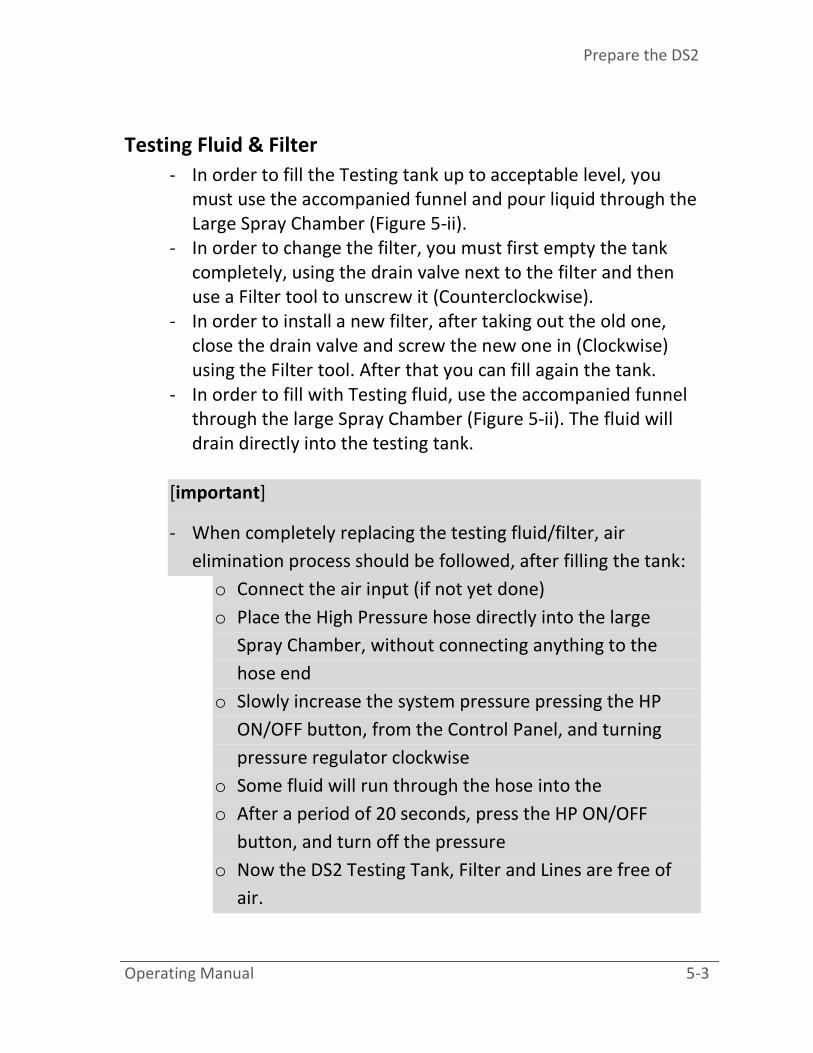
Testing Fluid & Filter
- In order to fill the Testing tank up to acceptable level, you
must use the accompanied funnel and pour liquid through the
Large Spray Chamber (Figure 5-ii).
- In order to change the filter, you must first empty the tank
completely, using the drain valve next to the filter and then
use a Filter tool to unscrew it (Counterclockwise).
- In order to install a new filter, after taking out the old one,
close the drain valve and screw the new one in (Clockwise)
using the Filter tool. After that you can fill again the tank.
- In order to fill with Testing fluid, use the accompanied funnel
through the large Spray Chamber (Figure 5-ii). The fluid will
drain directly into the testing tank.
[important]
- When completely replacing the testing fluid/filter, air
elimination process should be followed, after filling the tank:
o Connect the air input (if not yet done)
o Place the High Pressure hose directly into the large
Spray Chamber, without connecting anything to the
hose end
o Slowly increase the system pressure pressing the HP
ON/OFF button, from the Control Panel, and turning
pressure regulator clockwise
o Some fluid will run through the hose into the
o After a period of 20 seconds, press the HP ON/OFF
button, and turn off the pressure
o Now the DS2 Testing Tank, Filter and Lines are free of
air.

DS2 Series
5-4 Operating Manual
[info]
- After replacing the filter and filling the tank, drain some fluid
in order to eliminate some are pockets in the lines
- Fluid level is acceptable when it is visible through the level
indicator
- Always check fluid level when the DS2 is idle
- Never let the fluid level fall below the lowest visible point in
the tank level indicator
- Always consult Appendix A for Tank and Filter capacity and
specifications
- Excess Fluid can always be drained using the specified drain
valve

Prepare the DS2
Operating Manual 5-5
Figure 5-ii
Cleaning Fluid & Filter [DS2-X1 only]
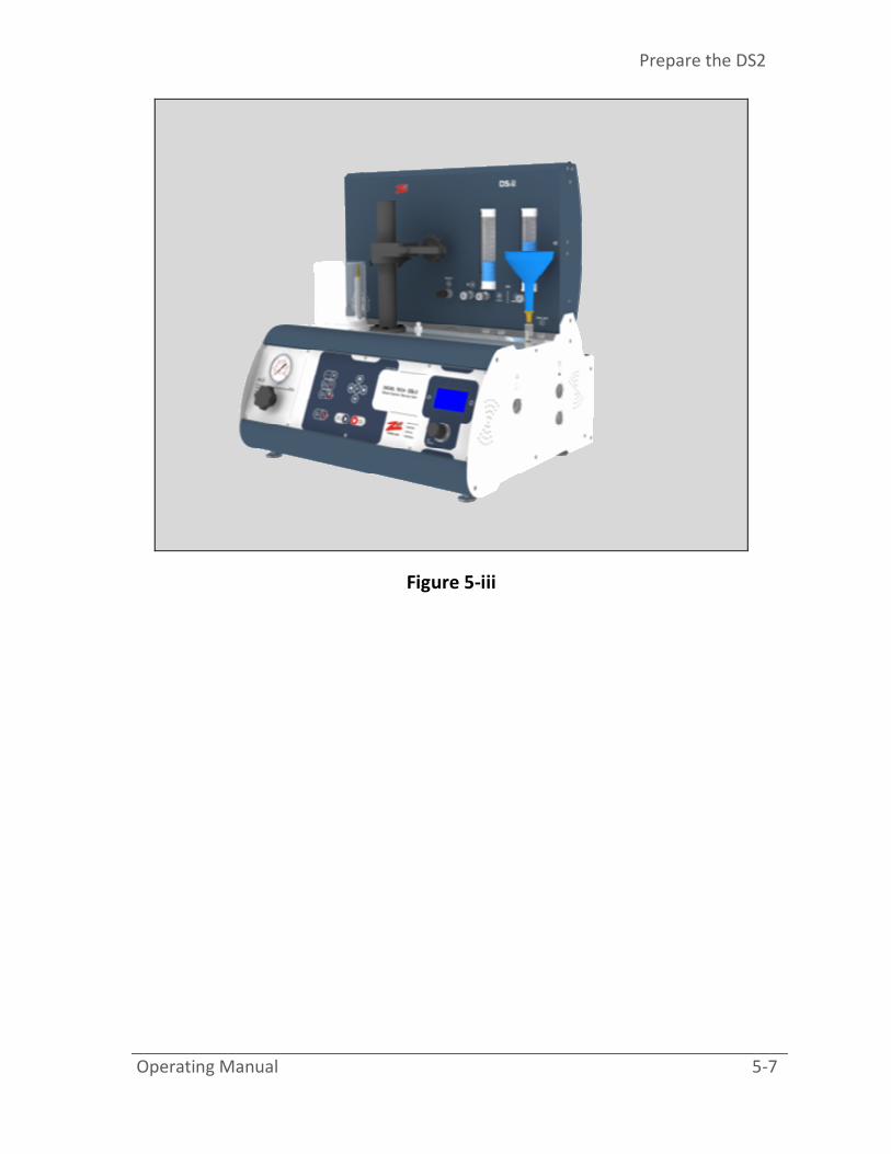
- In order to fill the Cleaning tank up to acceptable level, you
must use the accompanied funnel and pour liquid through the
[C] Cleaning port (Figure 5-iii).
- In order to change the filter, you must first empty the tank
completely, using the drain valve next to the filter and then
use a Filter tool to unscrew it (Counterclockwise).
- In order to install a new filter, after taking out the old one,
close the drain valve and screw the new one in (Clockwise)
using the Filter tool. After that you can fill again the tank.
[info]

DS2 Series
5-6 Operating Manual
- After replacing the filter and filling the tank, drain some fluid
in order to eliminate some are pockets in the lines
- Fluid level is acceptable when it is visible through the bottom
level indicator
- Always check fluid level when the DS2 is idle
- Never let the fluid level fall below the lowest visible point in
the tank level indicator
- Always consult Appendix A for Tank and Filter capacity and
specifications
- Excess Fluid can always be drained using the specified drain
valve
- The DS2 Software will provide a visual prompt on when to
change the Filter.
Prepare the DS2
Operating Manual 5-7
Figure 5-iii

Operation Basics
Operating Manual 6-1
“Operatio
n Basics”
In this chapter instructions with figures will be shown on how to
perform a basic operation with the DS2 unit. The following topics
are covered:
- Cleaning Injectors with ultrasonic device
- Injector Mounting
- Injector Clamp
- Injector Spray Chamber Clamping Position and connections
- Injector iVM Clamping Position and connections
- Sample Procedure on testing injectors
o Select the injector
o OHM test
o Spray test
o Volume test
- Injector MACC Clamping Position and connections
- Sample Procedure on MACC cleaning injectors
A new user should fully understand this chapter prior to
operating the DS2 unit.

DS2 Series
6-2 Operating Manual
Operation Basics
Operating Manual 6-3
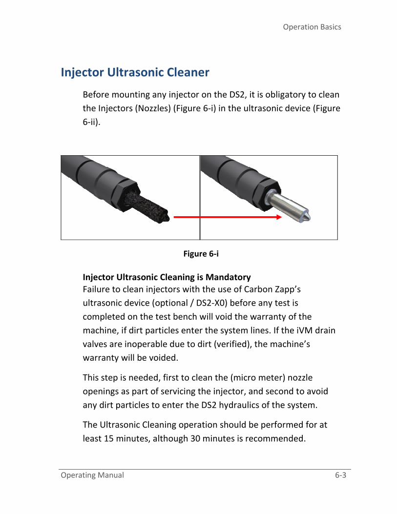
Injector Ultrasonic Cleaner
Before mounting any injector on the DS2, it is obligatory to clean
the Injectors (Nozzles) (Figure 6-i) in the ultrasonic device (Figure
6-ii).
Figure 6-i
Injector Ultrasonic Cleaning is Mandatory
Failure to clean injectors with the use of Carbon Zapp’s
ultrasonic device (optional / DS2-X0) before any test is
completed on the test bench will void the warranty of the
machine, if dirt particles enter the system lines. If the iVM drain
valves are inoperable due to dirt (verified), the machine’s
warranty will be voided.
This step is needed, first to clean the (micro meter) nozzle
openings as part of servicing the injector, and second to avoid
any dirt particles to enter the DS2 hydraulics of the system.
The Ultrasonic Cleaning operation should be performed for at
least 15 minutes, although 30 minutes is recommended.
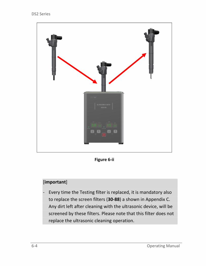
DS2 Series
6-4 Operating Manual
Figure 6-ii
[important]
- Every time the Testing filter is replaced, it is mandatory also
to replace the screen filters (30-88) a shown in Appendix C.
Any dirt left after cleaning with the ultrasonic device, will be
screened by these filters. Please note that this filter does not
replace the ultrasonic cleaning operation.
Operation Basics
Operating Manual 6-5
Injector Mounting
All the Common-Rail injectors can be mounted on the DS2, using
the Injector clamp (Figure 6-iii). Some injectors e.g. Side Feed
Injectors (e.g.: BOSCH INDUSTRIAL CRIN) may need additional
adapters. For further specifications on Clamping diameters,
please consult the Appendix A. For further guidance in Side Feed
Injector (CRIN) adapter mounting, please consult Appendix C.
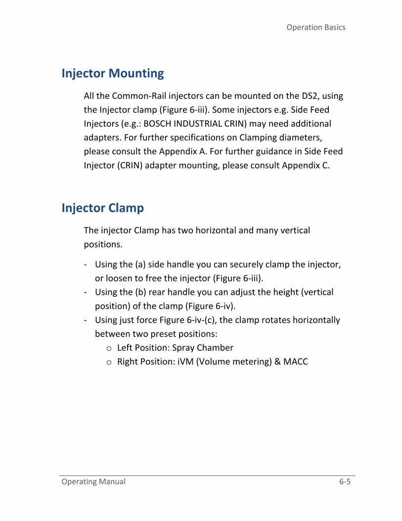
Injector Clamp
The injector Clamp has two horizontal and many vertical
positions.
- Using the (a) side handle you can securely clamp the injector,
or loosen to free the injector (Figure 6-iii).
- Using the (b) rear handle you can adjust the height (vertical
position) of the clamp (Figure 6-iv).
- Using just force Figure 6-iv-(c), the clamp rotates horizontally
between two preset positions:
o Left Position: Spray Chamber
o Right Position: iVM (Volume metering) & MACC

DS2 Series
6-6 Operating Manual
Figure 6-iii
(a)

Operation Basics
Operating Manual 6-7
Figure 6-iv
(b)
(c)
(c)
(b)
DS2 Series
6-8 Operating Manual
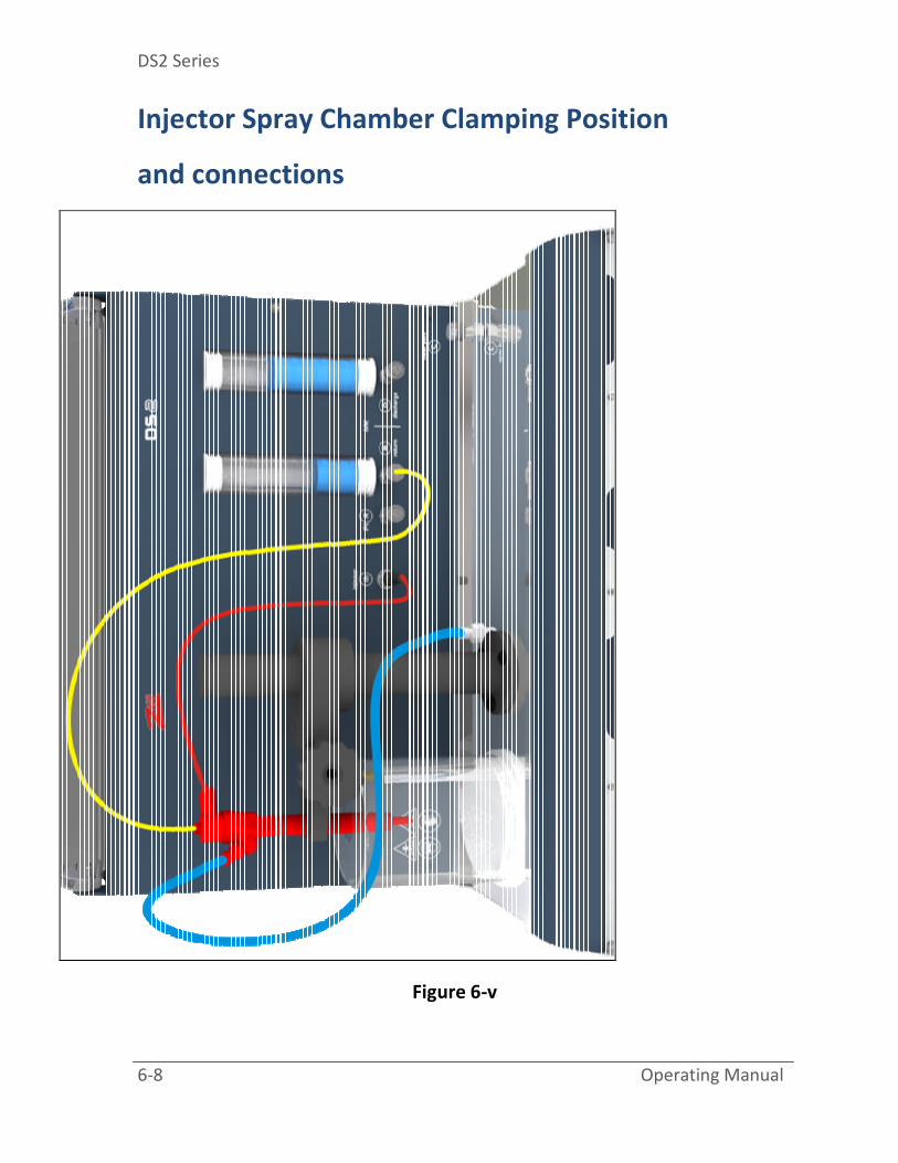
Injector Spray Chamber Clamping Position
and connections
Figure 6-v
Operation Basics
Operating Manual 6-9
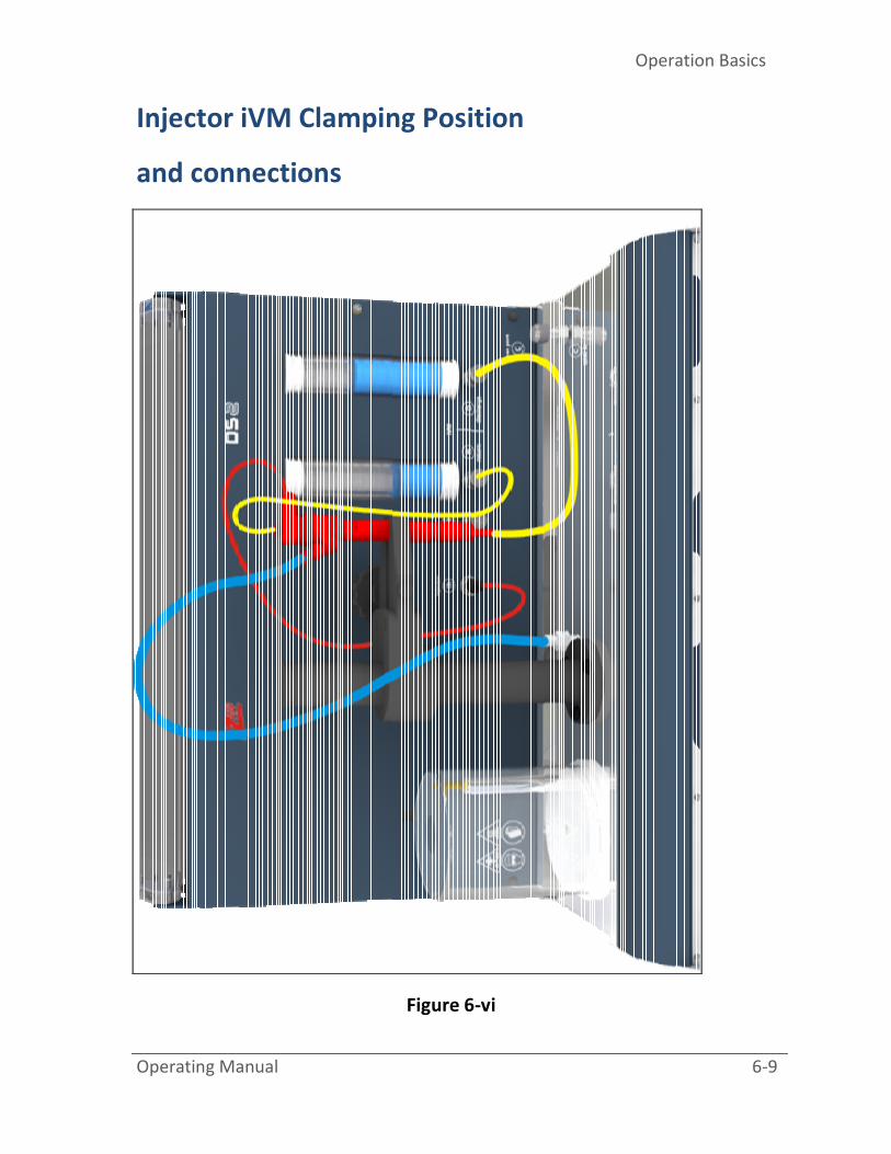
Injector iVM Clamping Position
and connections
Figure 6-vi

DS2 Series
6-10 Operating Manual
Sample Procedure on Testing Injectors
[important]
- Always expect pressure in fluid lines, and wear protective
goggles and gloves. For DS-1X models were the clear
protective cover is not a standard option, extra care is advised
when dealing with high pressures.
- It is recommended to observe the condition of the screen
filters (30-88) before each operation a shown in Appendix C.
- Every time the Testing filter is replaced, it is mandatory also
to replace the screen filters (30-88) a shown in Appendix C.
[info]
- If the Test is performed for a Piezo injector, please consult the
Appendix C for PIR (Piezo Injector Return) connectivity
instructions and procedure.
- When Switching injectors, it may be needed to perform a de-
aeration in the high pressure lines, a shown in Appendix C.
1: Select the injector
a. Consult the screens in Chapter 4 on how to select the
correct injector.
2: OHM Test
a. This test is only performed for Coil Injectors, because
Piezo Injectors don not have measurable resistance.
b. When this test is performed, 1 of 3 values will be
displayed:

Operation Basics
Operating Manual 6-11
i. OHM value of the injector
ii. OPEN (Open Coil Circuit)
iii. SHORT (Short Coil Circuit)
3: Spray Test
a. The Injector should be in the Spray Chamber clamping
position.
b. Use the R-Adapt and [ih] electrical harness.
c. The will begin after the OHM test, and the vacuum and
light will be automatically activated. The time and test
plans can be altered from the SETTINGS menu.
d. Use the HP Pressure Control Regulator to increase or
decrease the system pressure.
[info]
- If the [F]unction button is pressed while a single injection
program is running, using the arrow keys the operator can
dynamically change the Strokes and milliseconds of the test
plan.
4: iVM (Injector Volume Metering)
a. Important: Please clean injectors in the ultrasonic
device, for at least 15 minutes, prior to mounting on
the DS2 unit. Injector Ultrasonic Cleaning is Mandatory
(Please review the Warranty).
Failure to clean injectors with the use of Carbon Zapp’s
ultrasonic device (provided) before any test is completed
on the test bench will void the warranty of the machine.
If the sensor reading is out of specification or accuracy
due to dirt (verified), the machine’s warranty will be
voided.

DS2 Series
6-12 Operating Manual
b. The Injector should be in the iVM clamping position.
c. Use the D-adapt, R-adapt and [ih] electrical harness, and
connect the injector with the DS2.
d. Each Test Plan will perform for a predefined time,
measuring both [D]ischarge and [R]eturn volume per
Test plan.
e. Once each test plan is performed, the unit will provide
some time for the operator to record the volume values
from the [R] AND [D] tubes.
f. The operator can either perform the next test plan by
pressing ENTER/CANCEL button, or use the arrow keys
to select a specific test plan.
[info]
- Before each test plan is performed, an automatic Draining of
the tubes will also be performed. The operator can cancel the
draining procedure at any time by pressing the CANCEL
button.
5: CANCEL/STOP button in each test screen
a. If the CANCEL/STOP button is pressed once, during a
test, the current test will stop. By pressing the CANCEL
button twice or for more than 3 seconds, the software
will initialize to the home screen.

Operation Basics
Operating Manual 6-13
Injector MACC Clamping Position and connections
Figure 6-vii

DS2 Series
6-14 Operating Manual
MACC (Cleaning Injectors internally)
[DS2-X1 only]
The DS2 provides a separate function for cleaning injectors with
the MACC (Molecule Activated Chemical Cleaning) method.
Navigate to the Tests Screen and press the "F" button. The
Cleaning Screen will appear. Follow the steps below to
effectively service the injectors:
1. Mount the injector on the DS2 in the MACC clamping
position.
2. Use the C-adapt and [ih] electrical harness, and connect
the injector with the DS2 (Figure 6-iv).
3. Press the START button and the MACC process will begin.
4. Four predefined test plans will activate the injector in
different frequencies for the full period of the time for
more effective servicing.
5. As soon as this process has terminated, the program will
remain in idle mode, and the operator can either repeat
the process or Return to the Home Screen.
6. While exiting the MACC procedure, the DS2 will perform a
Flush program, that will flush the injector and lines with
Testing fluid, and it will drain the mixed fluid in the MACC /
Cleaning tank.
Operation Basics
Operating Manual 6-15
[IMPORTANT]
- The MACC hydraulic system is considered separate from the
Testing system, please use all adapters, hoses and connectors
marked with a “C”.
- It is important to follow the Flushing procedure after the
MACC cleaning. If the Flushing procedure is not performed for
any reason, please redo the MACC procedure in order to
perform the Flushing of the injector and lines.


Troubleshooting
Operating Manual 7-1
“Troubles
hooting”
Carbon Zapp designed the DS2 unit for durability. However, should
problems occur, following the procedures in this chapter can help to
determine the cause.
All DS2 operators should become familiar with this chapter. Knowing
what might go wrong can help prevent problems from occurring.

DS2 Series
7-2 Operating Manual
Symptom /
Problem
Detailed
Description Cause / Solution / Repair
No Boot / Start-
up
• File System is corrupt
• Perform a Full System Restore /
reprogram PCB board via RS232
with latest version software.
• or contact
LCD screen
• LCD Screen was scratched /
vandalized. Needs replacement.
• or Contact:
CONTROL
PANEL
BASED
PROBLEMS
Software Update
procedure
• Follow instructions shown in
Appendix C.

Troubleshooting
Operating Manual 7-3
INJECTOR DRIVER
PCB board issues
• Good Injector not working
correctly (Spray, Ohm):
- Check the FFA (fast fuse
adapter) connected on the
PCB board and the injector
wiring, for continuity while
the unit is switched off. If
there is no continuity on
either pins, replace the FFA
with one provided
• Injector Driver is defective,
contact:
MACHINE
LEAKS FLUIDS
INTERNALLY
WHILE
OPERATING
Possible LOW
PRESSURE Leaks
from:
1. Low Pressure
Supply Hoses
filter assembly
and HP pump
2. [D] and [R]
hoses
internally
connecting to
iVM system
3. iVM system
hoses
• Open both side panels of machine
• Operate unit in Manual mode at
both spray test and iVM test
• Visually inspect for leaks while
operating unit
• When leak is located, focus on the
origin of the problem.
• If a hose clamp is loose, tighten it
to solve the problem
• If there is a damaged or worn hose
or part, replace with equivalent
from the local market or contact
your closest Carbon Zapp dealer
for spare part
•Re-test unit after repairing to

DS2 Series
7-4 Operating Manual
hose
connecting to
machine
Cleaning tank
[DS2-X1 only]
6. Spray Chamber
drain Hose
7. Fumes
Extractor fluid
hose from
Spray Chamber
to rear side of
machine
8. Testing tank
gaskets or level
indicator
Cleaning tank
gaskets or level
indicator [DS2-
X1 only]
Possible HIGH
PRESSURE Leaks
Inside the
machine:
• Open both side panels of machine
• Operate unit in Manual mode at
spray test and adjust pressure at
200Bar
• Visually inspect for leaks while
operating unit. If there is no visual
leak, then increase gradually the
operating pressure in increments
of 50Bar until leak is visible
• When leak is located, focus on the
origin of the problem.
• If there is a damaged, loose or
worn HP hose or connector/part,
ONLY replace with new from your

Troubleshooting
Operating Manual 7-5
closest Carbon Zapp dealer
• Re-test unit after repairing to
verify the problem is solved
HP hose [D]
squirting fluid
from the
connectors or
the hose itself
• Replace complete HP hose with
new one supplied from your
closest Carbon Zapp dealer
BACK-LEAK [R]
hose leaking fluid
from the
connectors or
the hose itself
• Replace complete Back-Leak hose
with new one supplied from your
closest Carbon Zapp dealer
[D] or [R] QUICK
CONNECT
COUPLER AT
FRONT PANEL OF
MACHINE Is
leaking while
operating
([D]or[R] hose
connected
• Replace Quick connect coupler
with New one supplied from your
closest Carbon Zapp dealer
MACHINE
LEAKS FLUIDS
EXTERNALLY
WHILE
OPERATING
EXHAUST in
back-side of
machine is
spraying water
mist along with
air instead of dry
air
(Soaking wet
behind the
• Check Air supply circuit and water
trap (dehumidifier) of the shop for
water and dirt.
• Empty the water trap which is
located at the rear side of the
machine
• After this has been done, operate
again the machine for at least 5
minutes for the system to free the

DS2 Series
7-6 Operating Manual
of water, you need to contact your
hydraulic/air network provider to
check your system for humidity
and dehumidifier for possible
problem
EXHAUST in
back-side of
machine after
long operation
and humid
environment is
spraying a small
amount of water
mist along with
air instead of dry
air
(NOT soaking
wet behind the
machine)
• This is Normal operation of the
machine and pump does not
present a problem.
EXHAUST in
back-side of
machine is
spraying
calibration oil
mist along with
air instead of dry
air
• Pump will need to be replaced or
serviced from authorized
personnel only. Please contact you
nearest Carbon Zapp dealer to
report the problem or email to
[email protected] to be
send the service guide for
replacing or repairing the pump(s)
MACHINE
LEAKS FLUIDS
AT STAND-BY
Possible Leaks
from:
1. Testing tank
• Open both side panels of machine
• Visually inspect for leaks around
Troubleshooting
Operating Manual 7-7
gaskets or level
indicator
2. Cleaning tank
gaskets or level
indicator [DS2-
X1 only]
3. Low Pressure
Supply Hoses
to low
pressure
pump, filtering
system and HP
pump
the body of the unit
• When leak is located, focus on the
origin of the problem.
• If a hose clamp is loose, tighten it
to solve the problem
• If there is a damaged or worn hose
or part, replace with equivalent
from the local market or contact
your closest Carbon Zapp dealer
for spare part
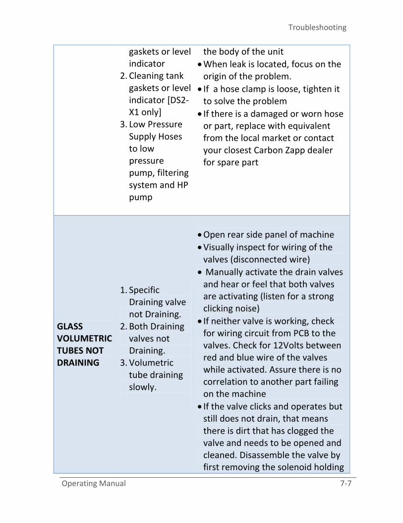
GLASS
VOLUMETRIC
TUBES NOT
DRAINING
1. Specific
Draining valve
not Draining.
2. Both Draining
valves not
Draining.
3. Volumetric
tube draining
slowly.
• Open rear side panel of machine
• Visually inspect for wiring of the
valves (disconnected wire)
• Manually activate the drain valves
and hear or feel that both valves
are activating (listen for a strong
clicking noise)
• If neither valve is working, check
for wiring circuit from PCB to the
valves. Check for 12Volts between
red and blue wire of the valves
while activated. Assure there is no
correlation to another part failing
on the machine
• If the valve clicks and operates but
still does not drain, that means
there is dirt that has clogged the
valve and needs to be opened and
cleaned. Disassemble the valve by
first removing the solenoid holding

DS2 Series
7-8 Operating Manual
nut, than unscrewing the valve
assembly screws and pulling
outwards all together. Wash off all
parts and reassemble
• If there is a damaged drain electro-
valve or part, replace with
equivalent from the local market or
contact your closest Carbon Zapp
dealer for spare part
Cracked or
broken Glass
tube
• Replace with new one. Contact
your closest Carbon Zapp dealer
for spare part
GLASS SPRAY
CHAMBER
Leaky Glass tube
• Remove Glass Tube by turning
counterclockwise and applying an
upward force
• Replace both Viton o-rings at the
base with equivalent from the local
market or contact your closest
Carbon Zapp dealer for spare part
• Replace the Glass tube in its
position and test
FLUID
PRESSURE
ISSUES NO or LOW
Pressure built-up
• Check Air Supply and verify that
the input specifications are
according to the ones listed at
Appendix A “Specifications”.
• Injector to be tested has a very
high back-leak value and injector
cannot built the required pressure
to operate
Troubleshooting
Operating Manual 7-9
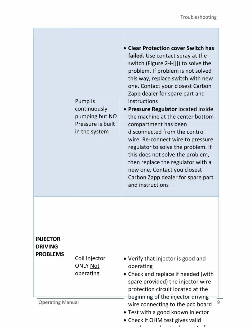
Pump is
continuously
pumping but NO
Pressure is built
in the system
• Clear Protection cover Switch has
failed. Use contact spray at the
switch (Figure 2-i-[j]) to solve the
problem. If problem is not solved
this way, replace switch with new
one. Contact your closest Carbon
Zapp dealer for spare part and
instructions
• Pressure Regulator located inside
the machine at the center bottom
compartment has been
disconnected from the control
wire. Re-connect wire to pressure
regulator to solve the problem. If
this does not solve the problem,
then replace the regulator with a
new one. Contact you closest
Carbon Zapp dealer for spare part
and instructions
INJECTOR
DRIVING
PROBLEMS
Coil Injector
ONLY Not
operating
• Verify that injector is good and
operating
• Check and replace if needed (with
spare provided) the injector wire
protection circuit located at the
beginning of the injector driving
wire connecting to the pcb board
• Test with a good known injector
• Check if OHM test gives valid
numbers and not values out of

DS2 Series
7-10 Operating Manual
driver circuit on the pcb board has
failed
• Contact you closest Carbon Zapp
dealer for spare part and
instructions
Piezo injector
ONLY Not
operating
• Verify that injector is good and
operating
• Check and replace if needed (with
spare provided) the injector wire
protection circuit located at the
beginning of the injector driving
wire connecting to the pcb board
• Test with a good known injector
• If Piezo does not work, test the
machine with a coil injector and
verify normal operation
• If test fails, then the high voltage
circuit on the PCB board has failed
• Contact you closest Carbon Zapp
dealer for spare part and
instructions
No injector
operation
• Verify that injector is good and
operating
• Check and replace if needed (with
spare provided) the injector wire
protection circuit located at the
beginning of the injector driving
wire connecting to the pcb board
• Test with a good known injector
• Check if OHM test gives valid
Troubleshooting
Operating Manual 7-11
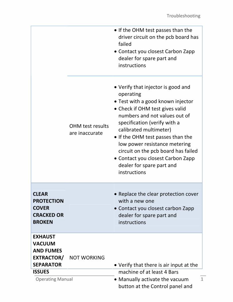
• If the OHM test passes than the
driver circuit on the pcb board has
failed
• Contact you closest Carbon Zapp
dealer for spare part and
instructions
OHM test results
are inaccurate
• Verify that injector is good and
operating
• Test with a good known injector
• Check if OHM test gives valid
numbers and not values out of
specification (verify with a
calibrated multimeter)
• If the OHM test passes than the
low power resistance metering
circuit on the pcb board has failed
• Contact you closest Carbon Zapp
dealer for spare part and
instructions
CLEAR
PROTECTION
COVER
CRACKED OR
BROKEN
• Replace the clear protection cover
with a new one
• Contact you closest carbon Zapp
dealer for spare part and
instructions
EXHAUST
VACUUM
AND FUMES
EXTRACTOR/
SEPARATOR
ISSUES
NOT WORKING
• Verify that there is air input at the
machine of at least 4 Bars
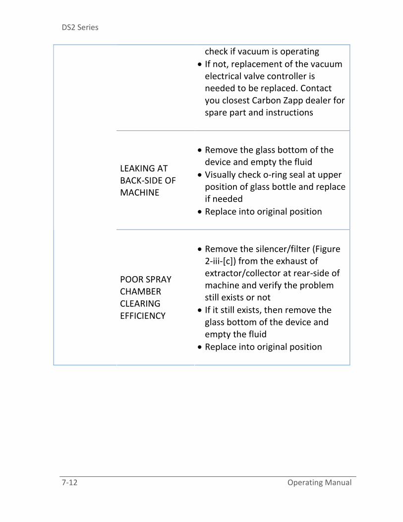
• Manually activate the vacuum
button at the Control panel and
DS2 Series
7-12 Operating Manual
check if vacuum is operating
• If not, replacement of the vacuum
electrical valve controller is
needed to be replaced. Contact
you closest Carbon Zapp dealer for
spare part and instructions
LEAKING AT
BACK-SIDE OF
MACHINE
• Remove the glass bottom of the
device and empty the fluid
• Visually check o-ring seal at upper
position of glass bottle and replace
if needed
• Replace into original position
POOR SPRAY
CHAMBER
CLEARING
EFFICIENCY
• Remove the silencer/filter (Figure
2-iii-[c]) from the exhaust of
extractor/collector at rear-side of
machine and verify the problem
still exists or not
• If it still exists, then remove the
glass bottom of the device and
empty the fluid
• Replace into original position
Specifications
Operating Manual A-1
Appendix A
“Specificat
ions”

DS2 Series
A-2 Operating Manual
Mains Voltage VAc 100-250 V
Mains Frequency Hz 50 / 60
Mains Fuse Ampere 5.0 A
Mains Power Cord (CE Approved)
Voltage/Amperage/Length V / A / mm
250 / 10 /
200
Power Consumption at Idle
Operation Watt 15.0
Power Consumption at Average
Operation Watt 100.0
Power Consumption at Max Watt 250.0
Outer dimensions W / D / H mm 605 / 702 /
730
Outer Max dimensions W / D / H
(Clear Protection Cover Open) mm
605 / 702 /
1015
Weight of DS2-X0 (Testing Unit only) Kg / Lbs 41.0 / 90
Weight of DS2-X1 (Testing & Cleaning
Unit) Kg / Lbs 44.0 / 97
Weight of DS2-X0 [Complete in Box] Kg / Lbs 56.0 / 123
Weight of DS2-X1 [Complete in Box] Kg / Lbs 67.0 / 148
Max. Filling Volume for
Testing/Calibration Oil Tank lt. / gal. 2.92 / 0.771
Filtering for Testing/Calibration Oil
(MANN 5-WK712/2 or Equivalent) μm 2.0
Testing Filter Life Hours 60
Testing Fluid Life Hours 20
Max. Filling Volume for Cleaning
Detergent Tank lt. / gal. 2.30 / 0.607
Filtering for Cleaning Detergent
(FLEETGUARD 7-FF-5074 or
Equivalent)
μm 8.0

Specifications
Operating Manual A-3
Cleaning Filter Life Hours 30
Cleaning Fluid Life Hours 10
Input System Pressure Bar / Psi 03-10 / 45-
145
Recommended Min. Operating
Pressure (for iVM) Bar / Psi 08 / 115
Min. Inner Diameter of Input Supply
Hose mm 10
Min. inner Diameter Exhaust Hose if
used to replace the Exhaust muffler
as shown in (Figure 3-iii)
mm 14
Max. System Build-Up Pressure Bar / Psi 1850 /
26,830
Injector Clamping diameters mm 9-45


Adapters and Connectors
Operating Manual B-1
Appendix B
“Adapters
and Conne
ctors”

DS2 Series
B-2 Operating Manual
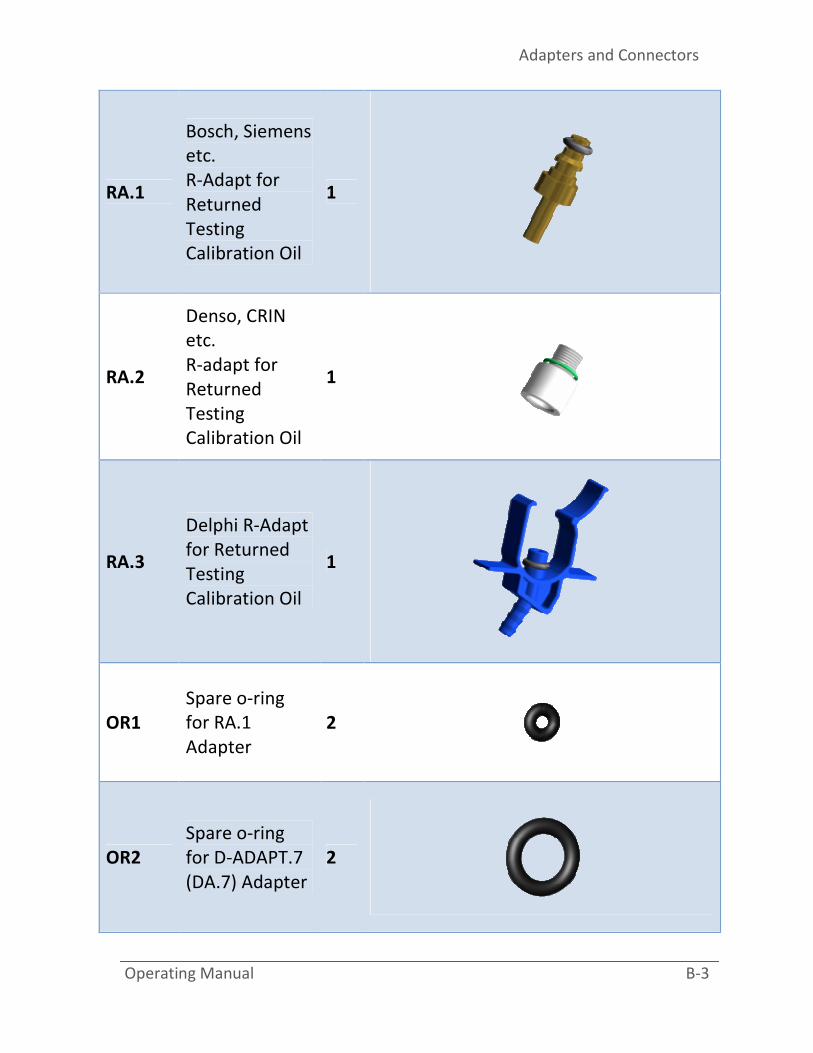
CODE DESCRIPTION Qty IMAGE
IH.1
Generic_1
Electrical
connector for
connector
[ih]
1
IH.2
Generic_2
Electrical
connector for
connector
[ih]
1
IH.3
Delphi
Electrical
connector for
connector
[ih]
1
HPT.14
High Pressure
Hose Extension
converter from
M12 to M14
HP-T
Connection
1
Adapters and Connectors
Operating Manual B-3
RA.1
Bosch, Siemens
etc.
R-Adapt for
Returned
Testing
Calibration Oil
1
RA.2
Denso, CRIN
etc.
R-adapt for
Returned
Testing
Calibration Oil
1
RA.3
Delphi R-Adapt
for Returned
Testing
Calibration Oil
1
OR1
Spare o-ring
for RA.1
Adapter
2
OR2
Spare o-ring
for D-ADAPT.7
(DA.7) Adapter
2
DS2 Series
B-4 Operating Manual
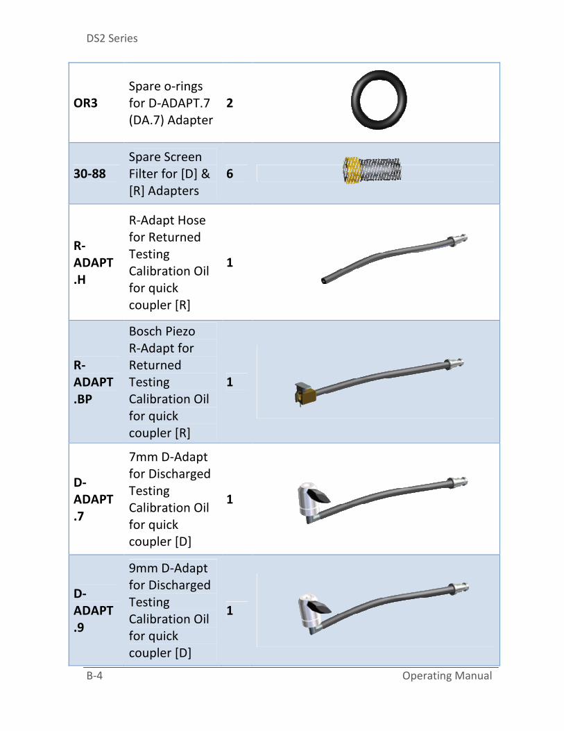
OR3
Spare o-rings
for D-ADAPT.7
(DA.7) Adapter
2
30-88
Spare Screen
Filter for [D] &
[R] Adapters
6
R-
ADAPT
.H
R-Adapt Hose
for Returned
Testing
Calibration Oil
for quick
coupler [R]
1
R-
ADAPT
.BP
Bosch Piezo
R-Adapt for
Returned
Testing
Calibration Oil
for quick
coupler [R]
1
D-
ADAPT
.7
7mm D-Adapt
for Discharged
Testing
Calibration Oil
for quick
coupler [D]
1
D-
ADAPT
.9
9mm D-Adapt
for Discharged
Testing
Calibration Oil
for quick
coupler [D]
1

Adapters and Connectors
Operating Manual B-5
T-FUN
Calibration
Oil/Fluid
Funnel – Large
1
DA.7
7mm Discharge
Adapter for
Cleaning MACC
for quick
coupler [C]
[DS2-X1 only]
1
DA.9
9mm Discharge
Adapter for
Cleaning MACC
(C-Adapt)
[DS2-X1 only]
1
RA.BP
Bosch Piezo
Return Adapter
for Returned
Cleaning MACC
C-Adapt
[DS2-X1 only]
1
DS2 Series
B-6 Operating Manual
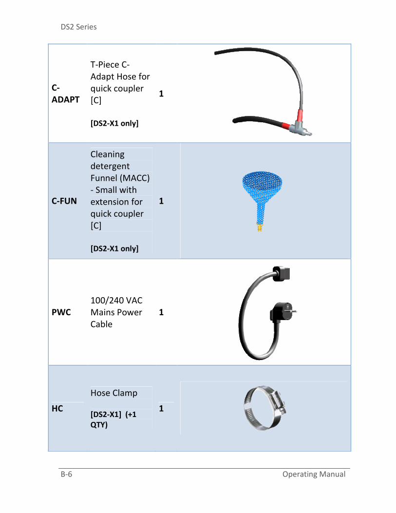
C-
ADAPT
T-Piece C-
Adapt Hose for
quick coupler
[C]
[DS2-X1 only]
1
C-FUN
Cleaning
detergent
Funnel (MACC)
- Small with
extension for
quick coupler
[C]
[DS2-X1 only]
1
PWC
100/240 VAC
Mains Power
Cable
1
HC
Hose Clamp
[DS2-X1] (+1
QTY)
1
Adapters and Connectors
Operating Manual B-7
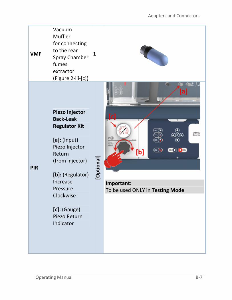
VMF
Vacuum
Muffler
for connecting
to the rear
Spray Chamber
fumes
extractor
(Figure 2-iii-[c])
1
PIR
Piezo Injector
Back-Leak
Regulator Kit
[a]: (Input)
Piezo Injector
Return
(from injector)
[b]: (Regulator)
Increase
Pressure
Clockwise
[c]: (Gauge)
Piezo Return
Indicator
[Op
tio
na
l]
Important:
To be used ONLY in Testing Mode
[a]
[b]
[c]


Connectivity Illustrations
Operating Manual C-1
Appendix C
“Connectiv
ity/Illustra
tions”

DS2 Series
C-2 Operating Manual
Description Illustration

Connectivity Illustrations
Operating Manual C-3
Electrical Wire
Connection
[ih] -> Injector
DS2 Series
C-4 Operating Manual
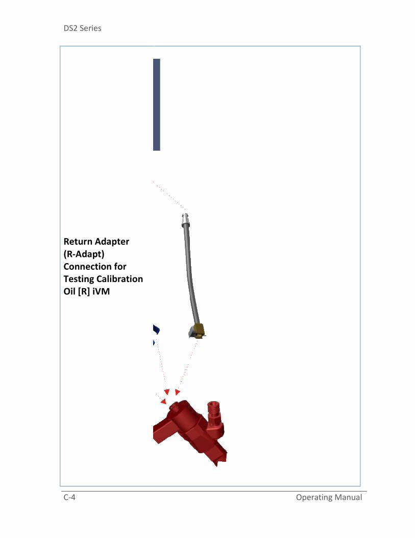
Return Adapter
(R-Adapt)
Connection for
Testing Calibration
Oil [R] iVM
Connectivity Illustrations
Operating Manual C-5
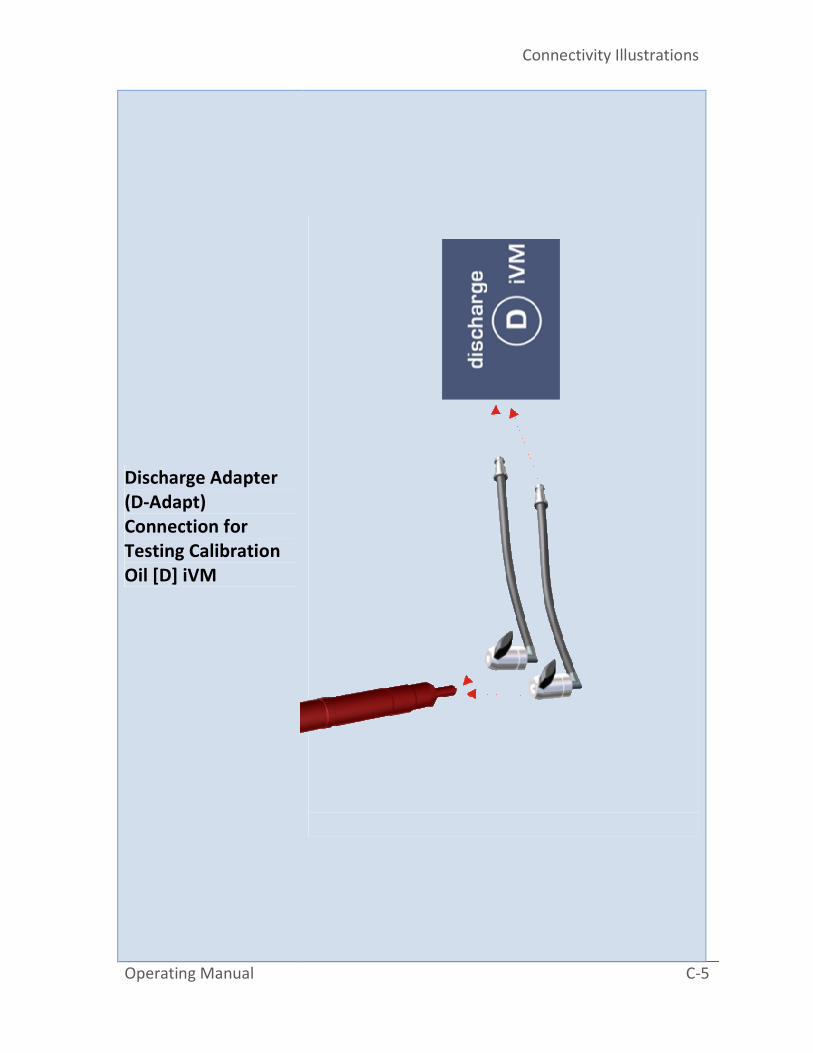
Discharge Adapter
(D-Adapt)
Connection for
Testing Calibration
Oil [D] iVM
DS2 Series
C-6 Operating Manual
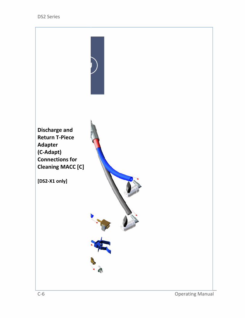
Discharge and
Return T-Piece
Adapter
(C-Adapt)
Connections for
Cleaning MACC [C]
[DS2-X1 only]

Connectivity Illustrations
Operating Manual C-7
“PIR”
Piezo Injector
Back-Leak Pressure
Regulator
DS2 Series
C-8 Operating Manual
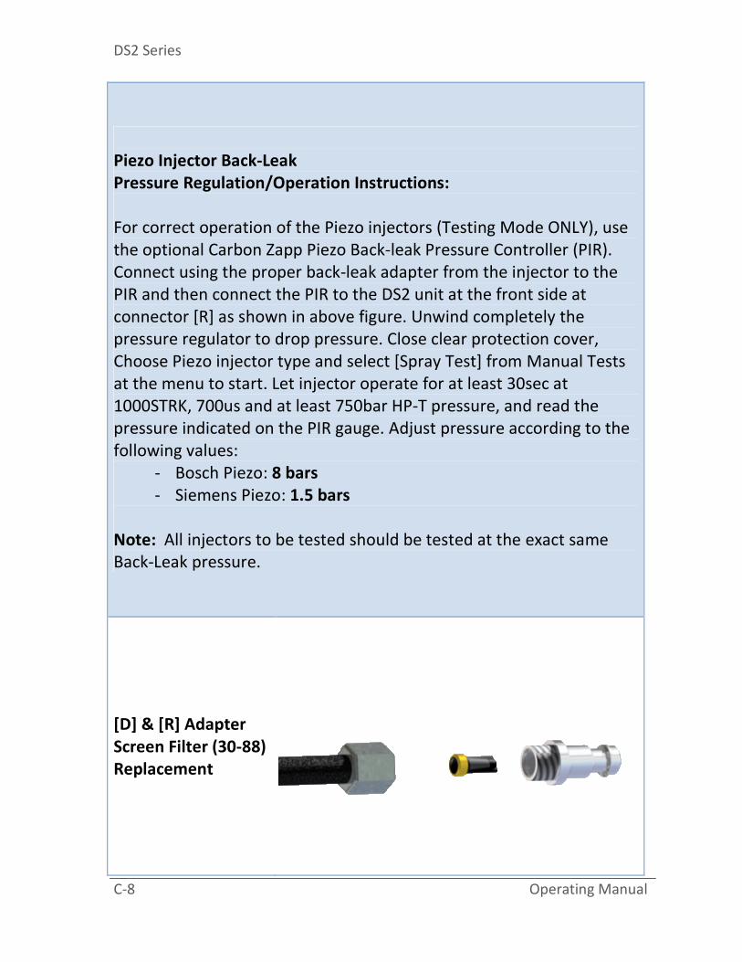
Piezo Injector Back-Leak
Pressure Regulation/Operation Instructions:
For correct operation of the Piezo injectors (Testing Mode ONLY), use
the optional Carbon Zapp Piezo Back-leak Pressure Controller (PIR).
Connect using the proper back-leak adapter from the injector to the
PIR and then connect the PIR to the DS2 unit at the front side at
connector [R] as shown in above figure. Unwind completely the
pressure regulator to drop pressure. Close clear protection cover,
Choose Piezo injector type and select [Spray Test] from Manual Tests
at the menu to start. Let injector operate for at least 30sec at
1000STRK, 700us and at least 750bar HP-T pressure, and read the
pressure indicated on the PIR gauge. Adjust pressure according to the
following values:
- Bosch Piezo: 8 bars
- Siemens Piezo: 1.5 bars
Note: All injectors to be tested should be tested at the exact same
Back-Leak pressure.
[D] & [R] Adapter
Screen Filter (30-88)
Replacement
Connectivity Illustrations
Operating Manual C-9
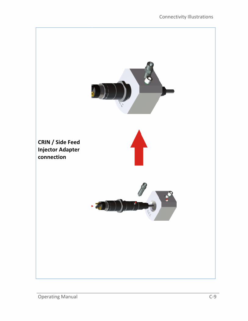
CRIN / Side Feed
Injector Adapter
connection

DS2 Series
C-10 Operating Manual
High Pressure lines
De-aeration
Air pockets in the High Pressure lines restrict
pressure build up, and therefore the HP pumps
will pulsate in a high frequency with almost
very low or no pressure build-up.
To bleed the system from air:
1. Connect the HP hose to the injector, and
tighten by hand
2. Release the HP pressure by unwinding the
HP regulator
3. Press the leak/PUMP button, to activate the
HP Pump
4. Slowly increase the HP Pressure by winding
the HP regulator (Clockwise). Remember
the High Pressure Safety Switch, it must be
pressed for the HP pressure to build up.
5. While the HP pump is pulsating in low
frequency and some liquid is flowing of the
HP hose, tighten the HP hose to the injector
with an appropriate wrench.
6. Close the Clear Protective Cover and
increase more pressure. Confirm that there
is no leak in the lines.

Connectivity Illustrations
Operating Manual C-11
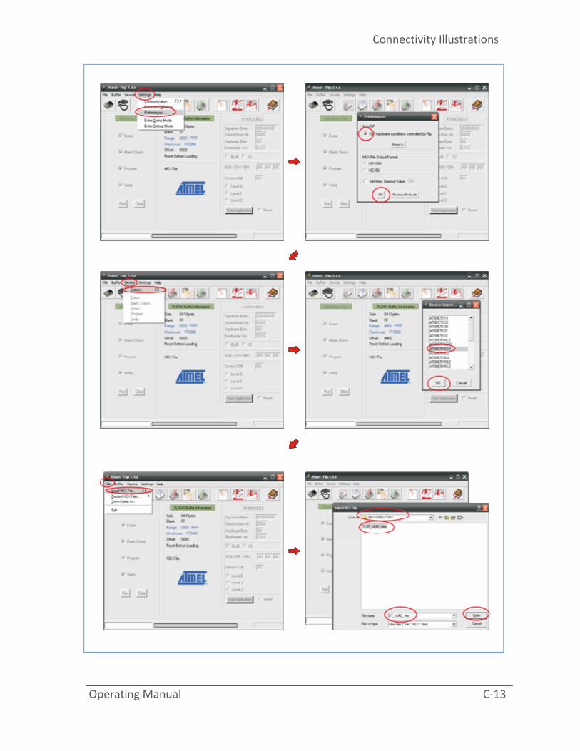
Software Update
Procedure
IMPORTANT: Disconnect any injectors from the
machine
(high risk of destroying the injector)!!!!!
NOTE: Read all the instruction once and then
proceed step by step.
Please visit the www.atmel.com web site,
search and download the latest FLIP utility in
order to update the software (search in AVR
Solutions / Tools & Software).
Direct Link:
http://www.atmel.com/dyn/products/tools_car
d.asp?tool_id=3886
Upon contact, you will be sent a .HEX file which
is the software file for the PCB boards.
Please follow the instructions below in order to
program the boards:
1. Acquire a PC or laptop that has a 9 pin
Serial COM port (or buy a USB-TO-
SERIAL(DB9) adapter from the local
computer market and install the required
software on that computer).
2. Save the FLIP program and the .HEX file
on that PC.
3. Unzip and Install the FLIP program on the
PC to be used.
4. (FLIP) Device->Select->AT89C51ED2
5. (FLIP) File -> Load HEX file
6. (FLIP) Settings -> Preferences -> ISP
Conditions controlled by Flip (this option
should always be checked)

DS2 Series
C-12 Operating Manual
7. Reveal the DS2 PCB board 9PIN SERIAL
connector by removing the side panel.
8. Connect the PC to the Boards COM port
using the 9 pin COM/SERIAL cable.
9. IMPORTANT: Disconnect any injectors
from the machine!!!!!
10. Power-up the machine.
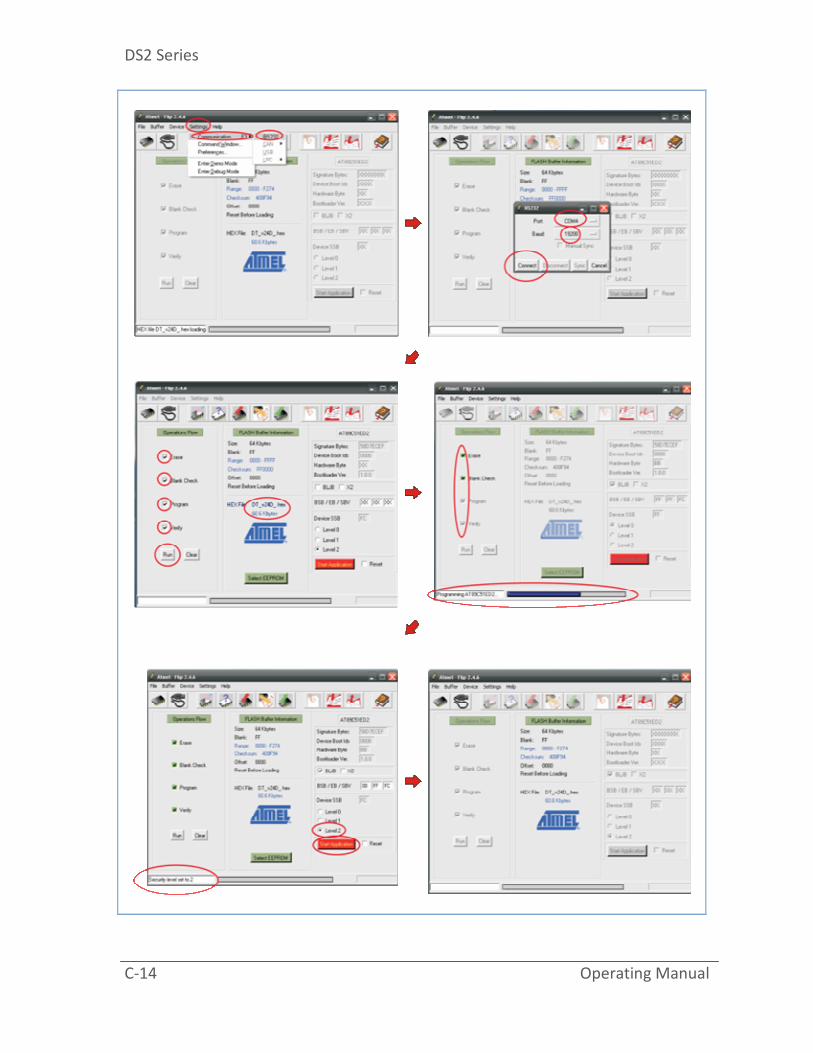
11. (FLIP) Settings->Communication->RS232-
>Port (COM1 or COMxx) -> Baud <=19200-
>Connect
12. If the PC already has a 9 pin Serial Port,
the COM number is usually COM1,
otherwise, open the Device Manager from
Windows System Properties, and look for
the USB-TO-SERIAL Device.
13. (FLIP) Make sure ERASE/BLACK
CHECK/PROGRAM/VERIFY are checked
and click on “Run”
14. (FLIP) When step 12 is done, check the
option “Level 2”, and then click on “START
APPLICATION”
15. Power Off the machine.
16. Disconnect the COM cable and power ON
the machine.
17. From the machines settings MENU, scroll
down to Option “LOAD DEFAULTS” and
press ENTER.
Below are some sample picture of the FLIP
utility.
Connectivity Illustrations
Operating Manual C-13
DS2 Series
C-14 Operating Manual

NOTES
