operation manual - america inter-m rm-8000(remote mic station) unpacking please take a few minutes...
TRANSCRIPT

RM-8000 Remote MIC Station
OperationManual
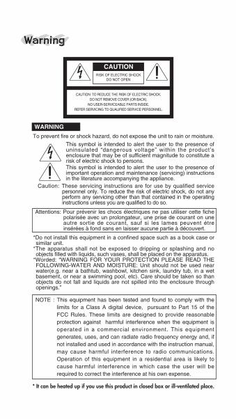
RISK OF ELECTRIC SHOCKDO NOT OPEN
CAUTION
CAUTION: TO REDUCE THE RISK OF ELECTRIC SHOCK.DO NOT REMOVE COVER (OR BACK).
NO USER-SERVICEABLE PARTS INSIDE.REFER SERVICING TO QUALIFIED SERVICE PERSONNEL.
WARNING
To prevent fire or shock hazard, do not expose the unit to rain or moisture.
This symbol is intended to alert the user to the presence ofuninsulated “dangerous voltage” within the product’senclosure that may be of sufficient magnitude to constitute arisk of electric shock to persons.This symbol is intended to alert the user to the presence ofimportant operation and maintenance (servicing) instructionsin the literature accompanying the appliance.
Caution: These servicing instructions are for use by qualified servicepersonnel only. To reduce the risk of electric shock, do not anyperform any servicing other than that contained in the operatinginstructions unless you are qualified to do so.
Attentions: Pour prévenir les chocs électriques ne pas utiliser cette fichepolarisée avec un prolongateur, une prise de courant on uneautre sortie de courant, sauf si les lames peuvent étreinsérées à fond sans en laisser aucune partie à découvert.
Warning
*Do not install this equipment in a confined space such as a book case orsimilar unit.
*The apparatus shall not be exposed to dripping or splashing and noobjects filled with liquids, such vases, shall be placed on the apparatus.
*Worded: “WARNING FOR YOUR PROTECTION PLEASE READ THEFOLLOWING-WATER AND MOISTURE: Unit should not be used nearwater(e.g. near a bathtub, washbowl, kitchen sink, laundry tub, in a wetbasement, or near a swimming pool, etc). Care should be taken so thanobjects do not fall and liquids are not spilled into the enclosure throughopenings.”
NOTE : This equipment has been tested and found to comply with thelimits for a Class A digital device, pursuant to Part 15 of theFCC Rules. These limits are designed to provide reasonableprotection against harmful interference when the equipment isoperated in a commercial environment. This equipmentgenerates, uses, and can radiate radio frequency energy and, ifnot installed and used in accordance with the instruction manual,may cause harmful interference to radio communications.Operation of this equipment in a residential area is likely tocause harmful interference in which case the user will berequired to correct the interference at his own expense.
* It can be heated up if you use this product in closed box or ill-ventilated place.

1RM-8000(REMOTE MIC STATION)
ContentsWelcome ................................................................2
Unpacking ..............................................................2
Short Form Instructions ..........................................2
InstallationEnvironment.........................................................4Important Safety Instructions ...............................4
Features .................................................................6
Front Panel.............................................................7
Rear Panel .............................................................9
Priority of Broadcasting ........................................11
Operation..............................................................11
Connection ...........................................................14
Block Diagram......................................................15
Specifications .......................................................16
ServiceProcedures.........................................................17Schematic ..........................................................17Parts List ............................................................17
Warranty...............................................................17

2 RM-8000(REMOTE MIC STATION)
UnpackingPlease take a few minutes to read this manual tofamiliarize yourself with important informationregarding installation, product features, and operation.
As with most electronic devices, ORIGINALPACKAGING (OR EQUAL) IS REQUIRED in theunlikely event that the product needs to be returnedfor servicing.
Short Form Instructions1. Do not connect the unit to the AC mains until some
preliminary settings are completed. AC mainsshould only be switched on later in this procedure.Ensure that the AC mains power and phantompower switches are in the OFF position.
2. Set all the output volume lever down to the minimum.
WelcomeA personal welcome to you from the managementand employees of Inter-M
All of the co-workers here at Inter-M are dedicatedto providing excellent products with inherentlygood value, and we are delighted you havepurchased one of our products.
We sincerely trust this product will provide yearsof satisfactory service, but if anything is not toyour complete satisfaction, we will endeavor tomake things right.
Welcome to Inter-M, and thank you for becomingpart of our worldwide extended family!

3RM-8000(REMOTE MIC STATION)
3. Connect each zone OUTPUT of the PX-8000 to thecorresponding zone of an amplified loudspeaker system.
4. Connect the LOCAL AUDIO SOURCES (tape deck,CD player, tuner, etc..) to the BGM inputs on thePX-8000 and turn the input gain control knobs (onthe rear panel) to half way.
5. Connect the AC mains power cord to the PX-8000and switch the AC mains power to the ON position.Switch ON the PHANTOM POWER if condensermicrophones will be used with this system.
6. Press the BGM select button located on the front paneluntil the illuminated number displays the desired inputchannel number for the local audio source.
7. Slowly side the output volume lever up on the frontpanel to increase the volume being sent to theamplifier for the loudspeaker system until thedesired level is reached. Obviously, if there isdistortion, feedback, or other cause for concern,reduce the signal level of the input or the output.
8. Connect one or more LM-8000 to each of theZONE connectors as needed. There is no need toset the address. Connect a remote audio source orremote microphone to the LM-8000. Use the gainand BGM select button on the unit instead of theones located on the PX-8000. The LM-8000 has ahigher priority than the PX-8000 and will overridethe gain and BGM Selection of the PX-8000.
9. Connect one or more (maximum 4) RM-8000 unitsto the remote mic input connector on the back ofthe PX-8000. Connect a microphone to each RM-8000. Select one or more zones using theselectors on the front of the RM-8000. Speak intothe microphone and adjust the signal level.
10. Set the level for each zone as desired by usingthe zone gain control on the PX-8000 or by usingthe gain control of the LM-8000, if soequipped.the PX-8000 to the corresponding zoneof an amplified loudspeaker system.

4 RM-8000(REMOTE MIC STATION)
InstallationEnvironmentNever place this product in an environment whichcould alter its performance or reduce its service life.Such environments usually include high levels ofheat, dust, moisture, and vibration.
Important Safety Instructions1. Read these instructions.2. Keep these instructions.3. Heed all warnings.4. Follow all instructions.5. Do not use this apparatus near water.6. Clean only with dry cloth.7. Do not block any ventilation openings. Install in
accordance with the manufacturer’s instructions.8. Do not install near any heat sources such as
radiators, heat registers, stoves, or otherapparatus (including amplifiers) that produce heat.
9. Do not defeat the safety purpose of the polarizedor grounding-type plug. A polarized plug has twoblades with one wider than the other. A groundingtype plug has two blades and a third groundingprong. The wide blade or the third prong areprovided for your safety. If the provided plug doesnot fit into your outlet, consult an electrician forreplacement of the obsolete outlet.
10. Protect the power cord from being walked onor pinched particularly at plugs, conveniencereceptacles, and the point where they exit fromthe apparatus.
11. Only use attachments/accessories specified bythe manufacturer.
12. Use only with the cart, stand,tripod, bracket, or table specifiedby the manufacturer, or sold withthe apparatus. When a cart isused, use caution when moving S3125A

5RM-8000(REMOTE MIC STATION)
the cart/apparatus combination to avoid injury fromtip-over.
13. Unplug this apparatus during lightning storms orwhen unused for long periods of time.
14. Refer all servicing to qualified service personnel.Servicing is required when the apparatus has beendamaged in any way, such as power-supply cordor plug is damaged, liquid has been spilled orobjects have fallen into the apparatus, theapparatus has been exposed to rain or moisture,does not operate normally, or has been dropped.
- AVOID EXCESSIVE HEAT, HUMIDITY, DUST ANDVIBRATIONKeep the unit away from locations where it is likely tobe exposed to high temperatures or humidity-such asnear radiators, stoves, etc. Also avoid locationswhich are subject to excessive dust accumulation, orto vibration that could cause mechanical damage.
- AVOID PHYSICAL SHOCKSStrong physical shocks to the unit may causedamage. Handle the unit with care.
- DO NOT OPEN THE CASE OR ATTEMPT REPAIRSOR MODIFICATIONS YOURSELFThis product contains no user-serviceable parts.Refer all maintenance to qualified Inter-M servicepersonnel. Opening the case and/or tampering withinternal circuitry voids the warranty.
- ALWAYS POWER OFF BEFORE MAKING CONNECTIONSAlways turn the AC mains OFF before connecting ordisconnecting cables. This is important to preventdamage to the unit itself as well as other connectedequipment.
- HANDLE CABLES CAREFULLYAlways plug and unplug cables (including the ACmains power cord) by gripping the connector, not thecord.
- CLEAN WITH A SOFT DRY CLOTHNever use solvents such as benzine or paint thinnerto clean the unit. Wipe clean with a soft, dry cloth.

6 RM-8000(REMOTE MIC STATION)
Features■■ Convenient installation and construction without need
of ID setting.
■■■ Selection of various Chime broadcastings for MICbroadcasting (PRE/POST).
■■ Convenient priority broadcasting.
■■■ Adoption of output signal level display.
■■ Adoption of RS-422 communication method tosupport a long distance.

7RM-8000(REMOTE MIC STATION)
2 3
7
61
54
Front Panel
1111.LEVEL METER Displays level of the output volume in MIC broadcasting.
2222.MIC JACKA terminal to connect Condenser MIC.Dynamic MIC can be used.
3333. IN-USE LED Displays the using status of 4 Remote MIC Stations.
4444.POWER LED If power supply is applied, the Power LED turns on.
5555. ALL Has toggle function as a switch to select all broadcastingareas.

8 RM-8000(REMOTE MIC STATION)
6666. TALKBroadcasts with the button pressed, as a switch tostart broadcasting after selecting the broadcastingarea. Release the button to end broadcasting. Duringbroadcast, "R" is displayed on the relevant display ofboth PX-8000 and LM-8000.
7777. AREA SELECTION BUTTONTurns on if pressing the switch to select the area tobroadcast and turns off if pressing it again.
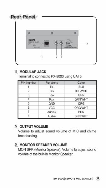
1111. MODULAR JACKTerminal to connect to PX-8000 using CAT5.
2222. OUTPUT VOLUMEVolume to adjust sound volume of MIC and chimebroadcasting.
3333. MONITOR SPEAKER VOLUMEMON SPK (Monitor Speaker): Volume to adjust soundvolume of the built-in Monitor Speaker.
9RM-8000(REMOTE MIC STATION)
4
321
Rear Panel
PIN Number12345678
Functions ColorTx- BLUTx+ BLU/WHTRx- GRNRx+ GRN/WHTGND ORGVCC ORG/WHT
Audio+ BRNAudio- BRN/WHT

10 RM-8000(REMOTE MIC STATION)
4444. CHIME MODE DIP S/WSwitch to select Chime Mode. Setting and operation issame as PAGING MIC chime function of PX-8000.A. SWITCH1 ON : Chime increased by 2 tones for
starting is broadcast whenpressing the TALK button.
B. SWITCH2 ON : Chime increased by 4 tones forstarting is broadcast whenpressing the TALK button.
C. SWITCH3 ON : Chime decreased by 4 tones forending is broadcast whenreleasing the TALK button.
D. SWITCH1, 2 ON : Same as for SWITCH1 ON.

11RM-8000(REMOTE MIC STATION)
Priority of BroadcastingThis system broadcasts according to following priority:PAGING MIC > FIRE ALARM (REC&PLAY IC) >RM-8000 MIC > LM-8000 > PX-8000 BGM
Operation■■ RM-8000 CONNECTION
- Connect to the RM-8000 connection hole on the rearside of PX-8000 using a CAT5 (UTP) wiring material.
- Immediate broadcasting is allowed without separateID setting.
- 4 sets of RM-8000 can be connected. - If powering on, buttons sequentially turn ON/OFF
simultaneously with power LED turned on.- Flashing of buttons mean defect of the unit or
connection status, thus check connection status andthe unit.
■■■ RM-8000 MIC BROADCASTING- Connect a MIC to the MIC input jack. Both dynamic
MIC and condenser MIC can be used.- Set the Chime Mode Switch on the rear side of
RM-8000.1) SWITCH1 ON : Chime increased by 2 tones for
starting broadcast is emittedwhen pressing the TALK button.
PX-8000 RM-8000

12 RM-8000(REMOTE MIC STATION)
2) SWITCH2 ON : Chime increased by 4 tones forstarting broadcast is emittedwhen pressing the TALK button.
3) SWITCH3 ON : Chime decreased by 4 tones forending broadcast is emittedwhen releasing the TALK button.
4) SWITCH1, 2 ON : Same as for SWITCH1 ON. - The button turns on if pressing the relevant button of
the area to broadcast. All zones of the PX-8000,where the relevant RM-8000 is connected, areselected if pressing the ALL button.
- MIC broadcasting is done with the TALK buttonpressed. In this case, perform broadcasting afterchecking start of Chime broadcasting using a built-inmonitor speaker.
- Adjust MIC output volume of RM-8000 and inputvolume of PX-8000 while listening to broadcastingvolume or checking the level meter.
- “R” is displayed on the BGM display window of PX-8000 and LM-8000 of the broadcasting area.
- Release the TALK button pressed to endbroadcasting. TALK button is on PTT method.
- Check ending of Chime broadcasting using a built-inmonitor speaker.
■■■ RM-8000 PRIORITY BROADCASTING- Broadcasting of any RM-8000 is allowed in the non-
broadcasting area.- Zone being broadcasting has priority with the
order of RM1 > RM2 > RM3 > RM4.- If the relevant area button turns off when pressing
the broadcasting area button and then pressing

13RM-8000(REMOTE MIC STATION)
TALK button, other RM is already broadcast in thesame area, and the user can know which RM-8000is broadcasting with the [IN-USE LED] turned on.
- If the area button selected during broadcasting turnsoff and the other [IN-USE LED] turns on, the otherRM-8000 with a high priority is broadcasting in thesame area.
■■■ RM-8000 BROADCASTING IN LINKED SYSTEMIf using the PX-8000 together, MIC broadcasting ofthe RM-8000 is not allowed to the output area of theother PX-8000. Broadcasting is allowed to only theoutput area of PX-8000 where the RM-8000 isconnected.

14 RM-8000(REMOTE MIC STATION)
Local BGM
PX-8000
LM-8000 LM-8000 LM-8000 LM-8000 LM-8000
Connections

15RM-8000(REMOTE MIC STATION)
Block Diagram

16 RM-8000(REMOTE MIC STATION)
Specifications
RM-8000
Audio Input MIC -50dB(Balanced)
Frequency Response (100Hz ~ 10kHz) ±3dB
S/N Better than 65dB
T.H.D. Less than 0.05%
Serial Communication Speed 9600 bpsInterface
Communication DistanceMaximum 300m(RS-422)(using UTP Cat5)
Operation Temperature -10℃ ~ +40℃
Power Source DC 24V, 300mA
Weight (SET) 1.5kg/3.2lb
Dimensions (SET) 200(W)x70(H)x206(D)mm7.9(W)x2.8(H)x8.1(D)in
* Specifications and design subject to change without notice.

ServiceProceduresEnsure the problem is not related to operator error, orexternal system devices, Once it is certain that theproblem is related to the product contact your warrantyprovider as described in the warranty section of thismanual.
SchematicA Schematic is available by contacting your warrantyprovider.
Parts ListA Parts List is available by contacting your warrantyprovider.
WarrantyWarranty terms and conditions vary by country and maynot be the same for all products. Terms and conditions ofwarranty for a given product may be determined first bylocating the appropriate country which the product waspurchased in, then by locating the product type.To obtain specific warranty information and availableservice locations contact Inter-M directly or the authorizedInter-M Distributor for your specific country or region.
17RM-8000(REMOTE MIC STATION)

MADE IN KOREAwww.inter-m.com
August 2007 9000004020
Inter-M, Ltd. (Korea) began operations in 1983.
Since then, Inter-M has grown to become one of the largest manufacturers of professional audio and commercial sound electronics equipment in the world.
Inter-M has gained worldwide recognition for its own branded products, as well as private label manufacturing of electronics sold under other names (OEM).
The company is no longer just a Korean company, but rather a global company that is truly international in scope, with factories and offices in Korea and China, and sales and marketing operations located in Japan, Europe, and the U.S.A.
With more than 850 employees around the globe,Inter-M is well-poised for further growth and expansion.
INTER-M AMERICAS, INC. 13875 ARTESIA BLVD. CERRITOS, CA 90703 USATEL : +1-562-921-0313, FAX : +1-562-921-0370Home Page : http://www.inter-m.net, E-mail : [email protected]
INTER-M CorporationSEOUL OFFICE:653-5 BANGHAK-DONG, DOBONG-KU, SEOUL, KOREA TEL : +82-2-2289-8140~8, FAX : +82-2-2289-8149Home Page : http://www.inter-m.com, E-mail : [email protected]