operation manual, 6.5rmy, 10-18 kw standby (tp-5631) literature/lit/tp5631...operation manual...
TRANSCRIPT

Operation Manual
Industrial Generator Sets
Models:6.5RMY
10-18RY/RZ
TP-5631 7/96
Controllers:Decision-Makert 3, 5-Light
Relay

Engine exhaust from this product containschemicals known to the State of California to causecancer, birth defects, or other reproductive harm.
WARNINGCalifornia Proposition 65
Table of ContentsSUBJECT PAGE SUBJECT PAGESafety Precautions and Instructions I. . . . . . .
Introduction i. . . . . . . . . . . . . . . . . . . . . . . . . . . . .
Service Assistance ii. . . . . . . . . . . . . . . . . . . . . . .
Section 1. Specifications 1-1. . . . . . . . . . . . . . . . .Introduction 1-1. . . . . . . . . . . . . . . . . . . . . . . . . . . . . . .Generator 1-1. . . . . . . . . . . . . . . . . . . . . . . . . . . . . . . .Controller 1-2. . . . . . . . . . . . . . . . . . . . . . . . . . . . . . . .
Controller Features 1-2. . . . . . . . . . . . . . . . . . . . . . . .Relay Controller 1-2. . . . . . . . . . . . . . . . . . . . . . . .5-Light Controller 1-2. . . . . . . . . . . . . . . . . . . . . . .
Accessories 1-3. . . . . . . . . . . . . . . . . . . . . . . . . . . . . .Overvoltage Kit
(microprocessor controller) 1-3. . . . . . . . . . . . . . . .Run Relay Kit 1-3. . . . . . . . . . . . . . . . . . . . . . . . . . . .Remote Annunciator Kit
(microprocessor controller) 1-4. . . . . . . . . . . . . . . .Audio-Visual (A/V) Alarm
(microprocessor controller) 1-5. . . . . . . . . . . . . . . .Line Circuit Breaker 1-5. . . . . . . . . . . . . . . . . . . . . . .Remote Emergency Stop Kit
(microprocessor controller) 1-6. . . . . . . . . . . . . . . .Single-Relay Dry Contact Kit
(microprocessor controller) 1-6. . . . . . . . . . . . . . . .Ten-Relay Dry Contact Kit
(microprocessor controller) 1-7. . . . . . . . . . . . . . . .Accessory Connection
(microprocessor controller) 1-7. . . . . . . . . . . . . . . .
Section 2. Operation 2-1. . . . . . . . . . . . . . . . . . . . .Prestart Checklist 2-1. . . . . . . . . . . . . . . . . . . . . . . . .Exercising the Generator 2-1. . . . . . . . . . . . . . . . . . .Microprocessor Controller Operation 2-2. . . . . . . . .
5-Light Microprocessor Controller 2-2. . . . . . . . . . .Microprocessor Controller Features 2-3. . . . . . .Start/Stop Procedure 2-6. . . . . . . . . . . . . . . . . . . .Stopping 2-6. . . . . . . . . . . . . . . . . . . . . . . . . . . . . .Circuit Protection
(microprocessor controller) 2-7. . . . . . . . . . . . .Fault Shutdowns 2-8. . . . . . . . . . . . . . . . . . . . . . .Controller Resetting Procedure
(Following Fault Shutdown) 2-9. . . . . . . . . . . .Resetting Emergency Stop Switches 2-9. . . . . .
Relay Controller Operation 2-10. . . . . . . . . . . . . . . . . .Starting/Stopping Procedure
(relay controller) 2-11. . . . . . . . . . . . . . . . . . . . . . . . .Starting 2-11. . . . . . . . . . . . . . . . . . . . . . . . . . . . . . .Stopping 2-11. . . . . . . . . . . . . . . . . . . . . . . . . . . . . .
Fault Shutdowns (relay controller) 2-11. . . . . . . . . . .Circuit Protection (relay controller) 2-12. . . . . . . . . . .
Voltage Regulator Fuse 2-12. . . . . . . . . . . . . . . . .
Controller Resetting Procedure(following fault shutdown) 2-13. . . . . . . . . . . . . . . . .
Section 3. Scheduled Maintenance 3-1. . . . . . . .Fuel Regulators 3-2. . . . . . . . . . . . . . . . . . . . . . . . . . .Carburetor Adjustments (LP/Natural Gas) 3-2. . . .LP Liquid Withdrawal Fuel System 3-2. . . . . . . . . . .Electronic Governor 3-3. . . . . . . . . . . . . . . . . . . . . . .Battery 3-3. . . . . . . . . . . . . . . . . . . . . . . . . . . . . . . . . . .
Battery Charging Systems 3-3. . . . . . . . . . . . . . . . .6.5 kW 3-3. . . . . . . . . . . . . . . . . . . . . . . . . . . . . . . .10-18 kW 3-3. . . . . . . . . . . . . . . . . . . . . . . . . . . . . .
Cleaning 3-4. . . . . . . . . . . . . . . . . . . . . . . . . . . . . . . . .Checking Electrolyte Level 3-4. . . . . . . . . . . . . . . . .Checking Specific Gravity 3-5. . . . . . . . . . . . . . . . . .
Generator Service 3-6. . . . . . . . . . . . . . . . . . . . . . . . .Storage Procedure 3-6. . . . . . . . . . . . . . . . . . . . . . . .
Engine oil 3-6. . . . . . . . . . . . . . . . . . . . . . . . . . . . .Fuel (gasoline-fueled engines) 3-6. . . . . . . . . . . .Fuel (gaseous-fueled engines) 3-6. . . . . . . . . . .Coolant (liquid-cooled models only) 3-6. . . . . . .Lubricate Cylinders 3-6. . . . . . . . . . . . . . . . . . . . .Exterior Preparation 3-6. . . . . . . . . . . . . . . . . . . .
Section 4. Troubleshooting 4-1. . . . . . . . . . . . . . .General Troubleshooting Chart
(Sheet 1 of 2) 4-1. . . . . . . . . . . . . . . . . . . . . . . . . . .General Troubleshooting Chart
(Sheet 2 of 2) 4-2. . . . . . . . . . . . . . . . . . . . . . . . . . .
Section 5. Generator Reconnection 5-1. . . . . . .Voltage Reconnection Procedure 5-1. . . . . . . . . . . .
Four-Lead (Single-Phase) Generator Sets 5-2. . . .100-120 Volt Configurations 5-2. . . . . . . . . . . . . .100-120/200-240 Volt 5-3. . . . . . . . . . . . . . . . . . .200-240 Volt 5-3. . . . . . . . . . . . . . . . . . . . . . . . . . .
12-Lead (Three-Phase) Generator Sets 5-4. . . . . .Reconnection Procedure
(Microprocessor Controller only) 5-5. . . . . . . .
Section 6. Installation 6-1. . . . . . . . . . . . . . . . . . . .General 6-1. . . . . . . . . . . . . . . . . . . . . . . . . . . . . . . . . .Air Requirements 6-1. . . . . . . . . . . . . . . . . . . . . . . . . .Exhaust Requirements 6-2. . . . . . . . . . . . . . . . . . . . .Fuel System 6-2. . . . . . . . . . . . . . . . . . . . . . . . . . . . . .Electrical Connections 6-3. . . . . . . . . . . . . . . . . . . . .
Battery 6-3. . . . . . . . . . . . . . . . . . . . . . . . . . . . . . . . . .Accessory Electrical Connections 6-3. . . . . . . . . . .AC Load Lead Connections 6-4. . . . . . . . . . . . . . . .
Appendix A. Glossary of Abbreviations A-1. . . .

TP-5631 7/96 Safety Precautions and Instructions I
Safety Precautions and InstructionsA generator set, like any other electromechanicaldevice, can pose potential dangers to life and limb ifimproperly maintained or operated. The best way toprevent accidents is to be aware of potential dangersand act safely. Please read and follow the safetyprecautions and instructions below to prevent harm toyourself and others. This manual contains severaltypes of safety precautions and instructions which areexplained below. SAVE THESE INSTRUCTIONS.
DANGER
Danger indicates the presence of a hazard that willcause severe personal injury, death, or substantialproperty damage.
WARNING
Warning indicates the presence of a hazard that cancause severe personal injury, death, or substantialproperty damage.
CAUTION
Caution indicates the presence of a hazard that will orcan cause minor personal injury or property damage.
NOTICE
Notice communicates installation, operation, ormaintenance information that is important but nothazard related.
Safety decals affixed to the generator set in prominentplaces advise the operator or service technician ofpotential hazards and how to act safely. The decals arereproduced in this publication to improve operatorrecognition. Replace missing or damaged decals.
II Safety Precautions and Instructions TP-5631 7/96
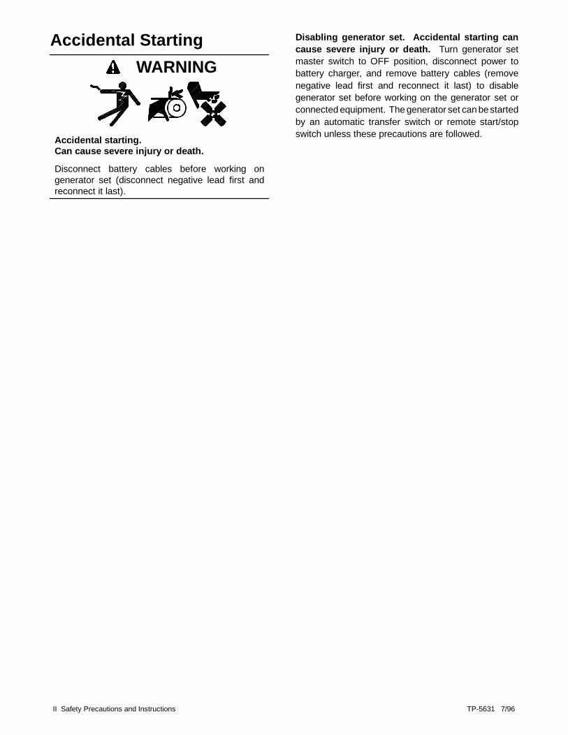
Accidental Starting
Accidental starting.Can cause severe injury or death.
Disconnect battery cables before working ongenerator set (disconnect negative lead first andreconnect it last).
WARNING
Disabling generator set. Accidental starting cancause severe injury or death. Turn generator setmaster switch to OFF position, disconnect power tobattery charger, and remove battery cables (removenegative lead first and reconnect it last) to disablegenerator set before working on the generator set orconnected equipment. The generator set can bestartedby an automatic transfer switch or remote start/stopswitch unless these precautions are followed.

TP-5631 7/96 Safety Precautions and Instructions III
Battery
Sulfuric acid in batteries.Can cause severe injury or death.
Use protective goggles and clothes. Battery acid cancause permanent damage to eyes, burn skin, and eatholes in clothing.
WARNING
WARNING
Explosion.Can cause severe injury or death. Relays inbattery charger cause arcs or sparks.
Locate battery in a well-ventilated area. Isolatebattery charger from explosive fumes.
Battery acid. Sulfuric acid in batteries can causesevere injury or death. Sulfuric acid in battery cancause permanent damage to eyes, burn skin, and eatholes in clothing. Always wear splash-proof safetygoggles when working near the battery. If battery acid issplashed in the eyes or on skin, immediately flush theaffected area for 15 minutes with large quantities ofclean water. Seek immediate medical aid in the case ofeye contact. Never add acid to a battery after placingthe battery in service, as this may result in hazardousspattering of battery acid.
Battery gases. Explosion can cause severe injuryor death. Battery gases can cause an explosion. Donot smoke or permit flame or spark to occur near abattery at any time, particularly when it is charging.Avoid touching terminals with tools, etc., to preventburns and sparks that could cause an explosion.Remove wristwatch, rings, and any other jewelry beforehandling battery. Never connect negative (--) batterycable to positive (+) connection terminal of startersolenoid. Do not test battery condition by shortingterminals together. Sparks could ignite battery gases orfuel vapors. Ventilate any compartment containingbatteries to prevent accumulation of explosive gases.To avoid sparks, do not disturb battery chargerconnections while battery is being charged. Always turnbattery charger off before disconnecting batteryconnections. Remove negative lead first and reconnectit last when disconnecting battery.

IV Safety Precautions and Instructions TP-5631 7/96
Engine Backfire/Flash Fire
WARNING
Fire.Can cause severe injury or death.
Do not smoke or permit flame or spark to occurnear fuel or fuel system.
Servicing fuel system. A flash fire can causesevere injury or death. Do not smoke or permit flameor spark to occur near carburetor, fuel line, fuel filter, fuelpump, or other potential sources of spilled fuel or fuelvapors. Catch all fuel in a suitable container whenremoving fuel line or carburetor.
Servicing air cleaner. A sudden backfire can causesevere injury or death. Do not operate with air cleanerremoved.

TP-5631 7/96 Safety Precautions and Instructions V
Exhaust System
WARNING
Carbon monoxide.Can cause severe nausea, fainting, or death.
The exhaust system must be leakproof androutinely inspected.
Generator set operation. Carbon monoxide cancause severe nausea, fainting, or death. Neveroperate the generator set inside a building unless theexhaust gas is piped safely outside. Never operate inany area where exhaust gas could accumulate andseep back inside a potentially occupied building. Avoidbreathing exhaust fumes when working on or near thegenerator set. Carbon monoxide is particularlydangerous because it is an odorless, colorless,tasteless, nonirritating gas. Be aware that it can causedeath if inhaled for even a short time.
Carbon monoxide symptoms. Carbon monoxidecan cause severe nausea, fainting, or death. Carbonmonoxide is a poisonous gas which is present inexhaust gases. Carbon monoxide poisoning symptomsinclude but are not limited to the following:
D Light-headedness, dizzinessD Physical fatigue, weakness in joints and musclesD Sleepiness, mental fatigue, inability to concentrate
or speak clearly, blurred visionD Stomachache, vomiting, nausea
If experiencing any of these symptoms and carbonmonoxide poisoning is possible, affected personsshould seek fresh air immediately. They should remainactive. They should not sit, lie down, or fall asleep. Alertothers to the possibility of carbon monoxide poisoning.If the condition of affected persons does not improvewithin minutes of breathing fresh air, they should seekmedical attention.

VI Safety Precautions and Instructions TP-5631 7/96
Fuel System
Explosive fuel vapors.Can cause severe injury or death.
Use extreme care when handling, storing,and using fuels.
WARNING
Fuel system. Explosive fuel vapors can causesevere injury or death. All fuels are highly explosive ina vapor state. Use extreme care when handling andstoring fuels. Store fuel in a well-ventilated area awayfrom spark-producing equipment and out of the reach ofchildren. Never add fuel to the tank while the engine isrunning since spilled fuel may ignite on contact with hotparts or from ignition spark. Do not smoke or permitflame or spark to occur near sources of spilled fuel orfuel vapors. Keep fuel lines and connections tight and ingood condition. Do not replace flexible fuel lines withrigid lines. Use flexible sections to avoid breakagecaused by vibration. Do not operate generator set in thepresence of fuel leaks, fuel accumulation, or sparks.Repair systems before resuming generator setoperation
Explosive fuel vapors can cause severe injury ordeath. Take additional precautions when using thefollowing fuels:
Gasoline— Store gasoline only in approved redcontainers clearly marked GASOLINE.
Propane (LP)— Adequate ventilation is mandatory.Propane is heavier than air; install propane gasdetectors low in room. Inspect detectors often.
Natural Gas— Adequate ventilation is mandatory.Natural gas rises; install natural gas detectors high inroom. Inspect detectors often.
Fuel tanks. Explosive fuel vapors can cause severeinjury or death. Gasoline and other volatile fuelsstored in day tanks or subbase fuel tanks can cause anexplosion. Store only diesel fuel in tanks.
Draining fuel system. Explosive fuel vapors cancause severe injury or death. Spilled fuel can causean explosion. Use a container to catch fuel whendraining fuel system. Wipe up all spilled fuel afterdraining system.
LP gas fuel leaks. Explosive fuel vapors can causesevere injury or death. Fuel leakage can cause anexplosion. Check LP vapor gas or natural gas fuelsystem for leakage using a soap-water solution with fuelsystem test pressurized to 6-8 ounces per square inch(10-14 inches water column). Do not use soapcontaining ammonia or chlorine in test solutions, sincethe soap will not bubble and will not allow an accurateleakage test.
LP liquid withdrawal fuel leaks. Explosive fuelvapors can cause severe injury or death. Fuelleakage can cause an explosion. Check LP liquidwithdrawal gas fuel system for leakage using asoap-water solution with fuel system test pressurizednot less than 90 psi (621 kPa). Do not use soapcontaining ammonia or chlorine in test solutions, sincethe soap will not bubble and will not allow an accurateleakage test.

TP-5631 7/96 Safety Precautions and Instructions VII
Hazardous Noise
Hazardous noise.Can cause loss of hearing.
Never operate generator set without a muffler orwith a faulty exhaust system.
CAUTION

VIII Safety Precautions and Instructions TP-5631 7/96
Hazardous Voltage/Electrical Shock
WARNING
Hazardous voltage. Moving rotor.
Can cause severe injury or death.
Operate generator set only with all guards andelectrical enclosures in place.
WARNING
Hazardous voltage.Backfeed to utility system can cause propertydamage, severe injury, or death.
If generator set is used for standby power, installan automatic transfer switch to prevent inadvertentinterconnection of standby and normal sources ofsupply.
Grounding generator set. Hazardous voltage cancause severe injury or death. Electrocution ispossible whenever electricity is present. Open maincircuit breakers of all power sources before servicingequipment. Configure the installation to electricallyground the generator set and electrical circuits when inuse. Never contact electrical leads or appliances whenstanding in water or on wet ground, as the chance ofelectrocution is increased under such conditions.
High voltage test. Hazardous voltage can causesevere injury or death. Follow instructions of testequipment manufacturer when performing high-voltagetest on rotor or stator. An improper test procedure candamage equipment or lead to future generator setfailures.
Installing battery charger. Hazardous voltage cancause severe injury or death. Electrical shock mayoccur if battery charger is not electrically grounded.Connect battery charger enclosure to ground of apermanent wiring system. As an alternative, install anequipment grounding conductor with circuit conductorsand connect to equipment grounding terminal or lead onbattery charger. Perform battery charger installation asprescribed in equipment manual. Install battery chargerin compliance with local codes and ordinances.
Connecting battery and battery charger.Hazardous voltage can cause severe injury ordeath. Reconnect battery correctly to avoid electricalshock and damage to battery charger and battery(ies).Have a qualified electrician install battery(ies).
Short circuits. Hazardous voltage can causesevere injury or death. Short circuits can cause bodilyinjury and/or equipment damage. Do not contactelectrical connections with tools or jewelry whileadjustments are made. Remove wristwatch, rings, andjewelry before servicing equipment.
Testing voltage regulator. Hazardous voltage cancause severe injury or death. High voltage is presentat the voltage regulator heat sink. Do not touch voltageregulator heat sink when testing or electrical shock willoccur.(PowerBoostt , PowerBoostt III, and PowerBoostt Vvoltage regulator models only.)
Engine block heater. Hazardous voltage can causesevere injury or death. Engine block heater can causeelectrical shock. Remove engine block heater plug fromelectrical outlet before working on block heater electricalconnections.
Electrical backfeed to utility. Hazardous backfeedvoltage can cause severe injury or death. Install atransfer switch in standby power installations to preventconnection of standby and other sources of power.Electrical backfeed into a utility electrical system cancause serious injury or death to utility personnel workingon transmission lines.

TP-5631 7/96 Safety Precautions and Instructions IX
Heavy Equipment
WARNING
Unbalanced weight.Improper lift can cause severe injury or deathand/or equipment damage.
Do not use lifting eyes.Lift generator set using lifting bars inserted throughskid lifting holes.

X Safety Precautions and Instructions TP-5631 7/96
Hot Parts
WARNING
Hot coolant and steam.Can cause severe injury or death.
Before removing pressure cap, stop generator setand allow it to cool. Then loosen pressure cap torelieve pressure.
WARNING
Hot engine and exhaust system.Can cause severe injury or death.
Do not work on generator set until it is allowed tocool.
Servicing generator. Hot parts can cause severeinjury or death. Avoid touching generator set field orexciter armature. Generator set field and exciterarmature when shorted become hot enough to causesevere burns.
Checking coolant level. Hot coolant can causesevere injury or death. Allow engine to cool. Releasepressure from cooling system before opening pressurecap. To release pressure, cover the pressure cap with athick cloth; then slowly turn it counterclockwise to thefirst stop. Remove cap after pressure has beencompletely released and the engine has cooled. Checkcoolant level at tank if generator set is equipped with acoolant recovery tank.
Servicing exhaust system. Hot parts can causesevere injury or death. Do not touch hot engine parts.An engine becomes hot while running and exhaustsystem components become extremely hot.

TP-5631 7/96 Safety Precautions and Instructions XI
Moving Parts
WARNING
Hazardous voltage. Moving rotor.
Can cause severe injury or death.
Operate generator set only with all guards andelectrical enclosures in place.
WARNING
Rotating parts.Can cause severe injury or death.
Do not operate generator set without all guards,screens, and covers in place.
Tightening hardware. Flying projectiles can causesevere injury or death. Retorque all crankshaft androtor hardware after servicing. Do not loosencrankshafthardware or rotor thrubolt when making adjustments orservicing generator set. Rotate crankshaft manually ina clockwise direction only. Turning crankshaft bolt orrotor thrubolt counterclockwise can loosen hardware.Loose hardware can cause hardware or pulley torelease from engine of generator set and can causepersonal injury.
Servicing generator set when operating. Exposedmoving parts can cause severe injury or death.Keep hands, feet, hair, clothing, and test leads awayfrom belts and pulleys when generator set is running.Replace guards, screens, and covers before operatinggenerator set.

XII Safety Precautions and Instructions TP-5631 7/96
Notice
NOTICEThis generator set has been rewired from itsnameplate voltage to:
246242
NOTICE
Voltage reconnection! Affix notice to generator setafter reconnecting to a voltage different than thenameplate. Order voltage reconnection decal 246242from authorized service distributors/dealers.
NOTICE
Hardware damage! Engine and generator set may useboth American Standard and metric hardware. Use thecorrect size tools to prevent rounding of bolt heads andnuts.
NOTICE
When replacing hardware, do not substitute withinferior grade hardware. Screws and nuts areavailable in different hardness ratings. AmericanStandard hardware uses a series of markings andmetric hardware uses a numeric system to indicatehardness. Check markings on bolt head and nuts foridentification.
NOTICE
Canadian installations only:For standby service connect output of generator set to asuitably rated transfer switch in accordance withCanadian Electrical Code, Part 1.

TP-5631 7/96 Introduction i
IntroductionAll information in this publication represents dataavailable at time of printing. Kohler Co. reserves theright to change this literature and the productsrepresented without incurring obligation.
Read through this manual and carefully follow allprocedures and safety precautions to ensure properequipment operation and to avoid bodily injury. Readand follow the Safety Precautions and Instructionssection at the beginning of this manual. Keep thismanual with equipment for future reference.
Equipment service requirements are minimal but arevery important to safe and efficient operation; therefore,inspect parts often and perform required service at theprescribed intervals. An authorized servicedistributor/dealer should perform required service tokeep equipment in top condition.
California EmissionCertification
If your engine/generator has this identification label, it iscertified for operation in the state of California.
IMPORTANT ENGINE INFORMATIONTHIS ENGINE MEETS 1995-1998
CALIFORNIA EMISSION CONTROLREGULATIONS FOR ULGE* ENGINES
DISPLACEMENT: __________________FAMILY: __________________
BUILD DATE: _________
REFER TO OWNERS MANUAL FORSAFETY, MAINTENANCE SPECS AND
ADJUSTMENTS. FOR SALES ANDSERVICE IN US/CANADA CALL:
1-800-544-2444
* Utility Lawn and Garden Equipment
This engine/generator is certified to operate on naturalgas or propane fuel.
This engine certified with engine modifications.

ii Introduction TP-5631 7/96
Service AssistanceFor sales and service in the U.S.A. and Canada checkthe yellow pages of the telephone directory under theheading GENERATORS— ELECTRIC for an authorizedservice distributor/dealer or call 1-800-544-2444.
For sales and service outside the U.S.A. and Canada,contact your local distributor.
For further information or questions, contact thecompany directly at the following address or number:
KOHLER CO., Kohler, Wisconsin 53044 U.S.A.Phone: 414-565-3381Fax: 414-459-1646 (U.S.A. Sales)
414-459-1614 (International)
To ensure supply of correct parts or information, makenote of the following identification numbers in thespaces provided:
GENERATOR SET
Model No.
Specification No.
Serial No.
MODEL, SPEC, and SERIAL numbers are found on thenameplate attached to the generator set.
Accessory Nos.
GENERATOR SET ACCESSORIES
An alternate nameplate inside the junction boxidentifies factory-installed generator set accessories.
ENGINE
Engine Serial No.
The engine serial number is found on the enginenameplate.

TP-5631 7/96 Specifications 1-1
Section 1. Specifications
IntroductionThe spec sheets for each generator set provide specificgenerator and engine information. Refer to therespective spec sheet for data not supplied in this
manual. Consult the generator set service manual,installation manual, engine operation manual, andengine service manual for additional specifications.
GeneratorThe generator is equipped with Kohler’s PowerBoosttvoltage regulation system which provides instantresponse to load changes.
PowerBoostt is a unique system that ensures reliablemotor starting and consistent voltage levels.
PowerBoostt utilizes a voltage monitoring system thatemploys a winding independent of the field to monitorand stabilize voltage.

1-2 Specifications TP-5631 7/96
Controller
Controller FeaturesThe generator set is equipped with either a relaycontroller or a 5-light microprocessor controller. For aspecific description of the controller, see Section 2,Operation. Controller features include the following:
Relay ControllerD Fault shutdowns with common indicator:
d Level, low coolant (liquid-cooled models only)d Overcrankd Overspeedd Pressure, low oild Temperature, high engine
D Running time meterD Switches and standard features:
d Cranking, cyclicd Start, remote two-wired Switch, run/off-reset/auto (engine start)
5-Light ControllerD Analog gauges, 2 in. (51 mm), 2% full-accuracy:
d Pressure gauge, oild Temperature gauge, engine water (liquid-cooled
models only)d Voltmeter, DC only
D Analog meters, 3.5 in. (89 mm):d AC ammeter, 2% full-scale accuracyd AC voltmeter, 2% full-scale accuracyd Frequency meter, 0.5% full-scale accuracy
D Fault shutdowns and status indicators:d Auxiliary (red)d Level, low coolant (uses auxiliary fault
indicator)(liquid-cooled models only)d Overcrank (red)d Overspeed (red)d Pressure, low oil (red)d Temperature, high engine (red)d Temperature, low water (red)*(liquid-cooled
models only)*Requires optional kit or user-provided devicefor lamp to function.
D Running time meterD Switches and standard features:
d Cranking, cyclicd Horn, alarm (with silence switch)d Rheostat, generator output voltage-adjusting
(front panel mounted, ±5% of nominal voltage)d Start, remote two-wired Switch, lamp testd Switch, meter range selectord Switch, run/off-reset/auto (engine start)d Timer, engine cool down (5-minute fixed)

TP-5631 7/96 Specifications 1-3
AccessoriesSeveral accessories are available to finalize theinstallation, to add convenience to operation andservice, and to comply with state and local codes.Accessories vary with each generator set model andcontroller. Accessories are offered factory-installed
and/or shipped loose. Some accessories are availableonly with the microprocessor controller. Contact yourlocal Kohler Dealer/Distributor to obtain the mostcurrent information. Accessories available at the time ofprint of this publication are as follows:
Overvoltage Kit(microprocessor controller)
The overvoltage circuit immediately shuts down theengine when triggered by a DC signal from anovervoltage shutdown option. The generator setautomatically shuts down if output voltage is 15% abovenominal voltage longer than one second. Theovervoltage option connects to wire 30 in the controller.See Figure 1-1.
G-291739
Figure 1-1. Overvoltage Kit
Run Relay KitThe run relay kit is energized only when the generatorset is running. The three sets of contacts in the kit aretypically used to control air intake and/or radiatorlouvers. However, alarms and other signalling devicescan also be connected to the contacts. Refer to theaccessory wiring diagram for correct connection of therun relay kit. See Figure 1-2.
273705
Figure 1-2. Run Relay Kit

1-4 Specifications TP-5631 7/96
Remote Annunciator Kit(microprocessor controller)
The remote annunciator allows convenient monitoringof the generator set’s condition from a remote location.The remote annunciator kit is available in surface mountand flush mount. A ten-relay dry contact kit is includedwith this kit. See Figure 1-3. The remote annunciatorincludes alarm horn, alarm silence switch, lamp test,
and the same lamp indicators as the 5-lightmicroprocessor controller, plus the following:
Line Power Lamp. Lamp lights when commercialutilitypower is in use.Generator Power Lamp. Lamp lights when generatorset power is in use.
Surface Mount Flush Mount
Dry Contact Kit
A-256472
A-258782
A-256452
Figure 1-3. Remote Annunciator

TP-5631 7/96 Specifications 1-5
Audio-Visual (A/V) Alarm(microprocessor controller)
An A/V alarm warns the operator of fault shutdowns andpre-alarm conditions (except battery charger fault andlow battery voltage) from a remote location. A/V alarmsinclude alarm horn, alarm silence switch, and commonfault lamp. See Figure 1-4.
NOTEConnect a maximum of three remote annunciatorsand/or A/V alarms in any combination to the generatorset controller.
A-292887
Figure 1-4. Audio-Visual Alarm
Line Circuit BreakerThe line circuit breaker interrupts generator output in theevent of an overload or short circuit. Use the line circuitbreaker to manually disconnect the generator set fromthe load when servicing the generator set. SeeFigure 1-5.
TP-5352-1
Figure 1-5. Line Circuit Breaker

1-6 Specifications TP-5631 7/96
Remote Emergency Stop Kit(microprocessor controller)
The emergency stop kit allows immediate shutdown ofthe generator set from a remote location. SeeFigure 1-6. The emergency stop lamp lights and thegenerator set shuts down if the emergency stop switchis activated. The generator set cannot be restarted untilthe emergency stop switch is reset (by replacing glasspiece) and the controller is reset by placing generatorset master switch in the OFF/RESET position.
A-222654
Figure 1-6. Emergency Stop Kit
Single-Relay Dry Contact Kit(microprocessor controller)
The single-relay dry contact kit uses one set of relaycontacts to trigger customer-provided warning devicesif a fault condition occurs. See Figure 1-7. A wiringharness included with the kit links the relay kit with thecontroller terminal strip or controller connection kit.Reference the accessory wiring diagram for correctconnection of the single-relay dry contact kit wiringharness. Connect the single-relay dry contact kit to anycontroller fault output (on TB1 terminal strip). Typicalconnections include:
Emergency StopAuxiliaryOverspeedLow Oil PressureHigh Engine Temperature
A-273945
Figure 1-7. Single-Relay Dry Contact Kit

TP-5631 7/96 Specifications 1-7
Ten-Relay Dry Contact Kit(microprocessor controller)
The ten-relay dry contact kit allows monitoring of thestandby system and/or the ability to activateaccessories such as derangement panels. The kitincludes ten sets of relay contacts for connection ofcustomer provided devices to generator set functions.Connect warning devices (lamps, audible alarms) andother accessories to the controller outputs listed.Connect a total of three dry contact kits to the controller.An internal view of the contact kit is shown in Figure 1-8.
Typical Contact Kit Output Connections:OverspeedOvercrankLow Oil PressureAuxiliary FaultEmergency Stop
A-273936
Figure 1-8. Ten-Relay Dry Contact Kit
Accessory Connection(microprocessor controller)
The Decision-Makerä 3 controller circuit board isequipped with a terminal strip (TB1) for easy connectionof generator set accessories. Do not direct connectaccessories to the controller terminal strip. Connect allaccessories to either a single-relay dry contact kit or to aten-relay dry contact kit. Connect the dry contact kit(s)to the controller terminal strip. Connect alarms, batterychargers, remote switches, and other accessories tothe dry contact kit relay(s) using 18 or 20 gaugestranded wire.
To connect accessories to the controller TB1 terminalstrip, lower the controller circuit board panel until it islying flat. Route dry contact relay leads through thecontroller port and guide loops to the circuit boardterminal strip. The controller circuit board panel must belying flat to ensure adequate slack in dry contact relayleads and/or harnesses. For specific information onaccessory connections, refer to Figure 1-10, theaccessory wiring diagram and the instruction sheetaccompanying each kit.

1-8 Specifications TP-5631 7/96
EmergencyStop
B+
B-
EmergencyStop
RemoteSwitch
AUX
OC
OS
LOP
HET
Common Fault **
** Common Fault IndicatorActivated By:
HET FaultLOP FaultLWT FaultOC FaultOS FaultAUX Fault
Connect A/V Alarm orCommon Fault Relay Kit
LWT
Remove Jumper ifEmergency Stop isUsed.
System Ready
Not In Auto
PHET
PLOP
Low FuelBattery Charging Fault
Low Battery
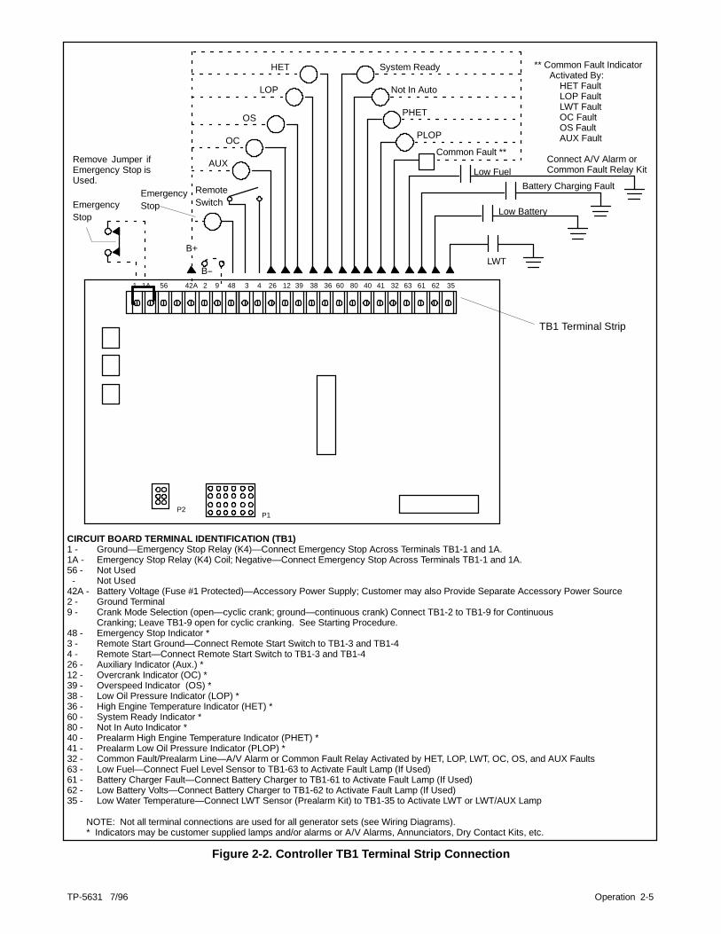
CIRCUIT BOARD TERMINAL IDENTIFICATION (TB1)1 - Ground— Emergency Stop Relay (K4)— Connect Emergency Stop Across Terminals TB1-1 and 1A.1A - Emergency Stop Relay (K4) Coil; Negative— Connect Emergency Stop Across Terminals TB1-1 and 1A.56 - Not Used- Not Used
42A - Battery Voltage (Fuse #1 Protected)— Accessory Power Supply; Customer may also Provide Separate Accessory Power Source2 - Ground Terminal9 - Crank Mode Selection (open— cyclic crank; ground— continuous crank) Connect TB1-2 to TB1-9 for Continuous
Cranking; Leave TB1-9 open for cyclic cranking. See Starting Procedure.48 - Emergency Stop Indicator *3 - Remote Start Ground— Connect Remote Start Switch to TB1-3 and TB1-44 - Remote Start— Connect Remote Start Switch to TB1-3 and TB1-426 - Auxiliary Indicator (Aux.) *12 - Overcrank Indicator (OC) *39 - Overspeed Indicator (OS) *38 - Low Oil Pressure Indicator (LOP) *36 - High Engine Temperature Indicator (HET) *60 - System Ready Indicator *80 - Not In Auto Indicator *40 - Prealarm High Engine Temperature Indicator (PHET) *41 - Prealarm Low Oil Pressure Indicator (PLOP) *32 - Common Fault/Prealarm Line— A/V Alarm or Common Fault Relay Activated by HET, LOP, LWT, OC, OS, and AUX Faults63 - Low Fuel— Connect Fuel Level Sensor to TB1-63 to Activate Fault Lamp (If Used)61 - Battery Charger Fault— Connect Battery Charger to TB1-61 to Activate Fault Lamp (If Used)62 - Low Battery Volts— Connect Battery Charger to TB1-62 to Activate Fault Lamp (If Used)35 - Low Water Temperature— Connect LWT Sensor (Prealarm Kit) to TB1-35 to Activate LWT or LWT/AUX Lamp
NOTE: Not all terminal connections are used for all generator sets (see Wiring Diagrams).* Indicators may be customer supplied lamps and/or alarms or A/V Alarms, Annunciators, Dry Contact Kits, etc.
TB1 Terminal Strip
1 42A 2 9 481A 56 3 4 26 12 39 38 36 60 80 40 41 32 63 61 62 35
P1P2
.
Figure 1-9. Controller TB1 Terminal Strip Connections
TP-5631 7/96 Operation 2-1
Section 2. Operation
Prestart ChecklistTo ensure continued satisfactory operation, check thefollowing items before each startup and at regularintervals. Refer to the engine service manual forspecific service procedures.
AIr Cleaner. Keep air cleaner element clean. Installelement to keep unfiltered air from entering engine.
Battery. Ensure tight battery connections. Maintain fullbattery electrolyte level.
Coolant Level (liquid-cooled models only). Checklevel after the engine has cooled. Maintain coolant levelat just below the overflow tube on the radiator filler neck.Open air-bleed petcocks, if equipped, when fillingradiator. Close air-bleed petcock when coolant beginsto flow from petcock. If equipped with a coolantrecovery tank, maintain level in tank between 1/3 full(cold) and 2/3 full (hot). Use a coolant solution of 50%ethylene glycol and 50% clean, softened water to inhibitrust/corrosion.
A coolant solution of 50% ethylene glycol providesfreezing protection of --34°F (--37°C) and overheatingprotection to 265°F (129°C). A coolant solution with lessthan 50% ethylene glycol may not provide adequatefreezing and overheating protection. A coolant solutionwith more than 50% ethylene glycol can cause engine orcomponent damage. Do not use alcohol or methanolantifreeze or mix them with the specified coolant.
Consult the engine manufacturer’s operation manual forengine coolant specifications.
Do not add coolant to a hot engine. Wait until engine hascooled. Adding coolant to a hot engine can cause thecylinder block or cylinder head to crack.
Do not energize block heater before filling coolingsystem. Before energizing block heater, run engine untilit is warm and refill radiator to purge air from the system.Immerse heater element in coolant to prevent blockheater failure.
Exhaust System. Keep exhaust outlet clear. Keepsilencer and piping tight and in good condition.
Fuel Level. Keep tank(s) full to ensure adequate fuelsupply.
Lamp Test. Press the lamp test button (if equipped) toverify operation of all controller LEDs.
Oil Level. Maintain oil level at or near full mark ondipstick but not over. Keep the oil level in themechanical governor (if equipped) at or near the fulllevel.
Operating Area. Check for obstructions that couldblock the flow of cooling air. Keep the air intake areaclean. Do not leave rags, tools, or debris on or near thegenerator set.
Exercising the GeneratorRun the generator set under load once each week forone hour. Perform this exercise in the presence of anoperator if the generator set does not have an automatictransfer switch with an exercise option.
Operator should perform all prestart checks beforestarting the exercise procedure. While the generator set
is running, listen for a smooth-running engine andvisually inspect the generator set to ensure there are nofluid or exhaust leaks.
Start the generator set according to the startingprocedure in the controller section of this manual.

2-2 Operation TP-5631 7/96
Microprocessor Controller Operation
5-Light Microprocessor Controller
1 2
35
78
10
12
9
17 18 19 20 21 22
6 4
11
16
13
14
15
PHPH
A-225183A-K1. Selector switch2. Alarm silence switch3. Lamp test4. Overcrank5. Generator master switch6. Auxiliary light7. Alarm horn8. DC voltmeter9. Voltage adjustment potentiometer
10. Oil pressure gauge11. Engine water temperature gauge (not used on 6.5 kW)
12. Hourmeter13. 15-amp engine and accessories fuse14. 3-amp controller fuse15. 3-amp remote annunciator fuse16. Fuse location17. Frequency meter18. AC voltmeter19. AC ammeter20. Overspeed light21. High engine temperature (not used on 6.5 kW)22. Low oil pressure lamp
Figure 2-1. 5-Light Microprocessor Controller Features

TP-5631 7/96 Operation 2-3
Microprocessor Controller FeaturesMicroprocessor controller features include theannunciator panel lamps, analog meters, switches andcontrols, fuses, and terminal strip. The followingparagraphs cover each of these topics.
LampsAuxiliary Fault. Lamp flashes or lights when fault isdetected.
Flashing Lamp ConditionsD The auxiliary lamp flashes immediately if the
controller senses no AC output while thegenerator set is running (except during the first10 seconds after start-up). The flashing stopsand the light is off when AC output is sensed.No manual reset is required.
D The auxiliary lamp flashes if the battery powerwas reconnected or was low and then cameback up again while the generator set masterswitch was in the RUN or AUTO position. Atemporarily low battery condition where thebattery is weak or undersized for the applicationis a possible cause. To clear this condition,place the generator set master switch in theOFF/RESET position.
Continuous On Lamp ConditionsD The auxiliary lamp lights and generator set
shuts down immediately if the emergency stopswitch is activated (if generator set is equippedwith optional emergency stop shutdownswitch).
D The auxiliary lamp lights if the optionalemergency stop switch is reset while thegenerator set master switch is in the AUTO orRUN position. Place the generator set masterswitch in OFF/RESET position to clear thiscondition.
D The auxiliary lamp lights and engine shutsdown 5 seconds after high oil temperature(P1-13) or auxiliary delay shutdown (P1-15)faults occur (if so equipped). These conditionsare inhibited during first 30 seconds after crankdisconnect.
D The auxiliary lamp lights and engine shutsdown immediately if an overvoltage conditionoccurs (if equipped with overvoltage shutdownkit).
D The auxiliary lamp lights and engine shutsdown immediately if activated by any customer-supplied sensing devices connected toauxiliary immediate shutdown ports (P1-17 andP1-18).
Low Oil Pressure. Lamp illuminates if generator setshuts down because of low oil pressure. Shutdownoccurs 5 seconds after engine reaches pressureshutdown range.
Overcrank. Lamp illuminates and cranking stops ifengine does not start after 45 seconds of continuouscranking or 75 seconds of cyclic cranking. See AutoStarting.
D Cranking stops and overcrank lamp illuminatesafter 15 seconds if starter or engine does notturn (locked rotor).
D Overcrank lamp flashes if speed sensor signalis absent longer than one second.
NOTEThe controller is equipped with an automaticrestart function. The generator set attempts torestart if the engine speed drops below 13 Hz(390 RPM). Continued decreased engine speedcauses an overcrank fault condition.
Overspeed. Lamp illuminates if generator set shutsdown because governed frequency on 50 and 60 Hzmodels exceeds 70 Hz (2100 RPM).
Analog MetersAC Ammeter. Meter measures amperage from outputleads. Use selector switch to choose output leadcircuits.
AC Voltmeter. Meter measures voltage across outputleads. Use selector switch to choose output leadcircuits.
DC Voltmeter. Meter measures voltage of startingbattery.
Frequency Meter. Meter measures frequency (Hz) ofgenerator set output voltage.
Hourmeter. Hourmeter records generator set totaloperating hours for reference in schedulingmaintenance.
2-4 Operation TP-5631 7/96
Switches and ControlsAlarm Horn. Horn sounds if any fault or anticipatorycondition exists. Place the generator set master switchin the AUTO position before silencing alarm horn. SeeController Resetting Procedure later in this section.
Alarm Silence. Switch disconnects alarm duringservice (place the generator set master switch in theAUTO position before silencing alarm horn). Restorealarm horn switches at all locations (controller, remoteannunciator, and audio/visual alarm) to normal positionafter fault shutdown is corrected to avoid reactivatingalarm horn. See Controller Resetting Procedure later inthis section.
Generator Master Switch(RUN/OFF-RESET/AUTO).Switch functions as controller reset and generator setoperation switch. Refer to Starting, Stopping, andController Resetting Procedure later in this section.
Lamp Test. Switch tests the controller indicator lamps.
Selector Switch. Switch selects generator outputcircuits to measure. When switched to a position withthree circuit lead labels, amperage is measured on theupper lead and voltage is measured between the lowertwo leads. AC ammeter and voltmeter do no registerwith switch in the OFF position.
Voltage Adjustment Potentiometer. Fine adjustment(±5%) for generator output voltage. See WiringDiagrams, Voltage Reconnection.
Fuses and Terminal StripFuses. Fuses are located on controller circuit board.
D 3-amp Remote Annunciator (F1). Fuseprotects remote annunciator circuit, A/V alarm,and isolated alarm kit (if equipped).
D 3-amp Controller. Fuse protects controllercircuit board, speed sensor, and lamp circuitboard.
D 15-amp Engine and Accessory. Fuseprotects engine/starting circuitry andaccessories.
Controller TB1 Terminal Strip (on Circuit Board).Connect generator set accessories such as emergencystop switch, remote start stop/switch, audio/visualalarms, etc., to the TB1 terminal strip. Make crankmode selection (cyclic or continuous) on the TB1terminal strip. Figure 2-2 shows the location of the TB1terminal strip on the controller circuit board. Refer toappropriate wiring diagrams for additional informationon connecting accessories to the TB1 terminal strip.
TP-5631 7/96 Operation 2-5
EmergencyStop
B+
B--
EmergencyStop
RemoteSwitch
AUX
OC
OS
LOP
HET
Common Fault **
** Common Fault IndicatorActivated By:
HET FaultLOP FaultLWT FaultOC FaultOS FaultAUX Fault
Connect A/V Alarm orCommon Fault Relay Kit
LWT
Remove Jumper ifEmergency Stop isUsed.
System Ready
Not In Auto
PHET
PLOP
Low FuelBattery Charging Fault
Low Battery
CIRCUIT BOARD TERMINAL IDENTIFICATION (TB1)1 - Ground— Emergency Stop Relay (K4)— Connect Emergency Stop Across Terminals TB1-1 and 1A.1A - Emergency Stop Relay (K4) Coil; Negative— Connect Emergency Stop Across Terminals TB1-1 and 1A.56 - Not Used- Not Used
42A - Battery Voltage (Fuse #1 Protected)— Accessory Power Supply; Customer may also Provide Separate Accessory Power Source2 - Ground Terminal9 - Crank Mode Selection (open— cyclic crank; ground— continuous crank) Connect TB1-2 to TB1-9 for Continuous
Cranking; Leave TB1-9 open for cyclic cranking. See Starting Procedure.48 - Emergency Stop Indicator *3 - Remote Start Ground— Connect Remote Start Switch to TB1-3 and TB1-44 - Remote Start— Connect Remote Start Switch to TB1-3 and TB1-426 - Auxiliary Indicator (Aux.) *12 - Overcrank Indicator (OC) *39 - Overspeed Indicator (OS) *38 - Low Oil Pressure Indicator (LOP) *36 - High Engine Temperature Indicator (HET) *60 - System Ready Indicator *80 - Not In Auto Indicator *40 - Prealarm High Engine Temperature Indicator (PHET) *41 - Prealarm Low Oil Pressure Indicator (PLOP) *32 - Common Fault/Prealarm Line— A/V Alarm or Common Fault Relay Activated by HET, LOP, LWT, OC, OS, and AUX Faults63 - Low Fuel— Connect Fuel Level Sensor to TB1-63 to Activate Fault Lamp (If Used)61 - Battery Charger Fault— Connect Battery Charger to TB1-61 to Activate Fault Lamp (If Used)62 - Low Battery Volts— Connect Battery Charger to TB1-62 to Activate Fault Lamp (If Used)35 - Low Water Temperature— Connect LWT Sensor (Prealarm Kit) to TB1-35 to Activate LWT or LWT/AUX Lamp
NOTE: Not all terminal connections are used for all generator sets (see Wiring Diagrams).* Indicators may be customer supplied lamps and/or alarms or A/V Alarms, Annunciators, Dry Contact Kits, etc.
TB1 Terminal Strip
1 42A 2 9 481A 56 3 4 26 12 39 38 36 60 80 40 41 32 63 61 62 35
P1P2
Figure 2-2. Controller TB1 Terminal Strip Connection

2-6 Operation TP-5631 7/96
Start/Stop Procedure
Local StartingPlace the generator set master switch in the RUNposition to start the generator set at the controller.
NOTEThe alarm horn sounds whenever the generator setmaster switch is not in the AUTO position.
NOTEThe microprocessor controller is equipped with atransient start/stop function to avoid accidental crankingof the rotating engine. If the generator set master switchis momentarily placed in the OFF/RESET position thenquickly returned to RUN, the genset slows to 249 rpmand recranks before returning to rated speed.
NOTEThe microprocessor controller is equipped with anautomatic restart function. The generator set attemptsto restart if the engine speed drops below 13 Hz(390 rpm). Failure to correct the cause of the decreasedengine speed results in an overcrank condition.
Auto (Remote) StartingPlace the generator set master switch to the AUTOposition for start-up by automatic transfer switch orremote start/stop switch (connected to controllerterminals TB1-3 and TB1-4).
Crank Mode SelectionThe microprocessor controller provides up to 45seconds of continuous cranking or 75 seconds of cycliccranking (crank 15 seconds, rest 15 seconds, crank 15seconds, etc.) before overcrank shutdown. Make thecranking mode (cyclic or continuous) selection on the
controller circuit board terminal strip. For cycliccranking, leave circuit board terminal TB1-9 open. Runa jumper between circuit board terminal TB1-2 (ground)and terminal TB1-9 for continuous cranking.
Stopping
Normal Stopping1. Disconnect load from generator set and allow it to
run without load for 5 minutes.
NOTERun the generator set at no load for 5 minutes priorto stopping to ensure adequate cooling of the set.
2. Place the generator set master switch in theOFF/RESET position. The engine stops.
NOTEThe generator set runs for a 5-minute cooldowncycle if engine stop is signaled by a remote switchor automatic transfer switch.
Emergency StoppingPlace the generator set master switch in theOFF/RESET position or activate remote emergencystop (if equipped) for immediate shutdown. Thecontroller AUXILIARY lamp lights and the generator setshuts down if the emergency stop switch is activated.The remote annunciator and/or audio-visual alarms, ifequipped, signal an emergency stop.
NOTEUse the emergency stop switch(s) for emergencyshutdowns only. Use the generator set master switch tostop the generator set under normal operatingconditions.
TP-5631 7/96 Operation 2-7
Circuit Protection(microprocessor controller)
An optional line circuit breaker (sized for generatoroutput) is available to protect the generator fromdamage because of overload or short circuits. If thecircuit breaker trips, reduce the load and switch thebreaker back to the ON position. With the breaker in theOFF position, the generator set runs but there is nooutput voltage.
NOTEIf the generator set circuit breaker trips repeatedly, seeSection 4, Troubleshooting for possible causes.
Fuses F1 (3-amp), F2 (3-amp) and F3 (15-amp) on thecontroller circuit board protect the engine and controllercircuitry. (See Fuses earlier in this section.) If thegenerator set will not crank or accessories will not work,and the battery/connections appear okay, one of thesefuses may be blown.
Fuses V7, V8, and V9 on the AC terminal block (TB2)protect the controller meters and lights. If the controllerlights and meters are not functioning, check thecondition of the V7, V8, and V9 fuses. If a fuse isreplaced and then blows again, see Section 4,Troubleshooting for possible causes.
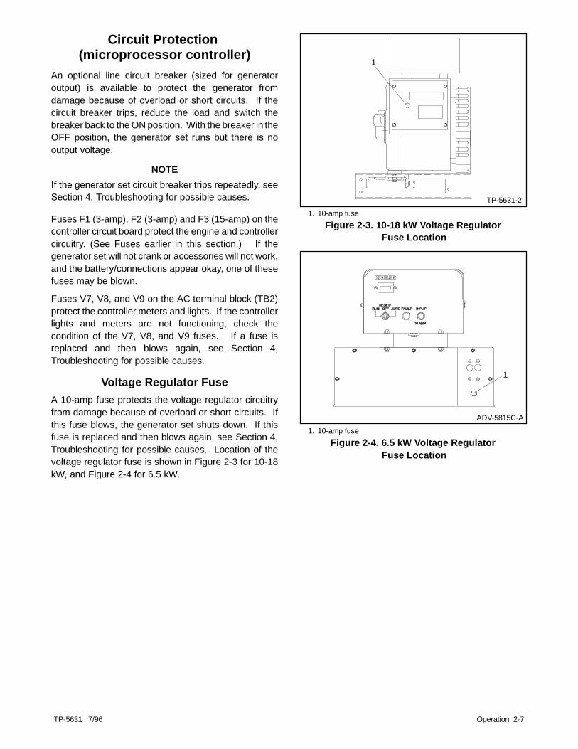
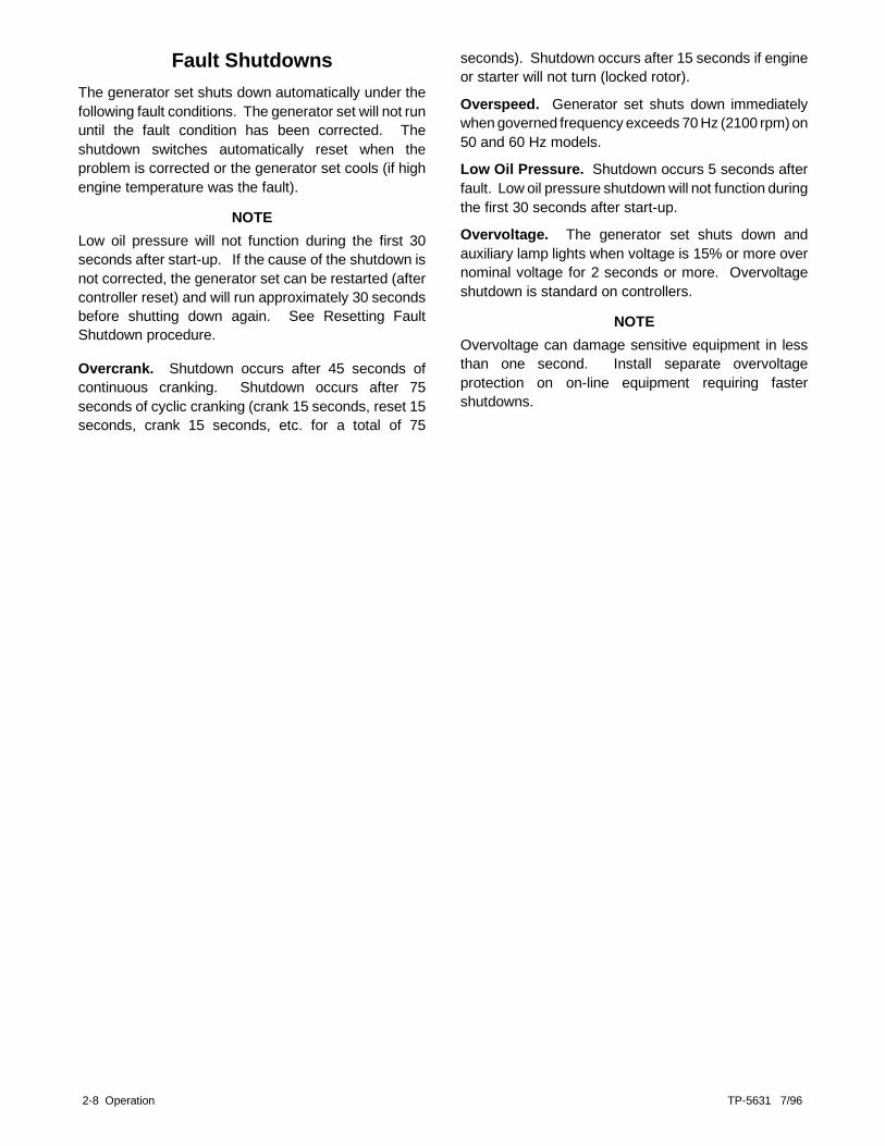
Voltage Regulator FuseA 10-amp fuse protects the voltage regulator circuitryfrom damage because of overload or short circuits. Ifthis fuse blows, the generator set shuts down. If thisfuse is replaced and then blows again, see Section 4,Troubleshooting for possible causes. Location of thevoltage regulator fuse is shown in Figure 2-3 for 10-18kW, and Figure 2-4 for 6.5 kW.
1
TP-5631-21. 10-amp fuse
Figure 2-3. 10-18 kW Voltage RegulatorFuse Location
ADV-5815C-A
1
1. 10-amp fuseFigure 2-4. 6.5 kW Voltage Regulator
Fuse Location
2-8 Operation TP-5631 7/96
Fault ShutdownsThe generator set shuts down automatically under thefollowing fault conditions. The generator set will not rununtil the fault condition has been corrected. Theshutdown switches automatically reset when theproblem is corrected or the generator set cools (if highengine temperature was the fault).
NOTELow oil pressure will not function during the first 30seconds after start-up. If the cause of the shutdown isnot corrected, the generator set can be restarted (aftercontroller reset) and will run approximately 30 secondsbefore shutting down again. See Resetting FaultShutdown procedure.
Overcrank. Shutdown occurs after 45 seconds ofcontinuous cranking. Shutdown occurs after 75seconds of cyclic cranking (crank 15 seconds, reset 15seconds, crank 15 seconds, etc. for a total of 75
seconds). Shutdown occurs after 15 seconds if engineor starter will not turn (locked rotor).
Overspeed. Generator set shuts down immediatelywhen governed frequency exceeds 70 Hz (2100 rpm) on50 and 60 Hz models.
Low Oil Pressure. Shutdown occurs 5 seconds afterfault. Low oil pressure shutdown will not function duringthe first 30 seconds after start-up.
Overvoltage. The generator set shuts down andauxiliary lamp lights when voltage is 15% or more overnominal voltage for 2 seconds or more. Overvoltageshutdown is standard on controllers.
NOTEOvervoltage can damage sensitive equipment in lessthan one second. Install separate overvoltageprotection on on-line equipment requiring fastershutdowns.

TP-5631 7/96 Operation 2-9
Controller Resetting Procedure(Following Fault Shutdown)
Use the following procedure to restart the generator setafter a fault shutdown. Refer to Resetting EmergencyStop Switches in this section to reset the generator setafter an emergency stop.
1. Place controller alarm horn switch in the SILENCEposition. A/V annunciator alarm horn and lamp areactivated, if equipped. Place A/V annunciatoralarm switch in SILENCE position to stop alarmhorn. A/V annunciator lamp stays lit. (The A/Valarm uses one lamp to indicate a fault shutdown;the appropriate fault lamp lights on the remoteannunciator to indicate a fault condition.)
2. Disconnect generator set from load with line circuitbreaker or automatic transfer switch.
3. Correct cause of fault shutdown. See SafetyPrecautions section of this manual beforeproceeding.
4. Place the generator set master switch in theOFF/RESET position and then in the RUN positionto start generator set. A/V annunciator alarm hornsounds and lamp, if equipped goes out.
5. Verify that cause of shutdown has been correctedby test operating generator set.
6. Reconnect generator set to load via line circuitbreaker or automatic transfer switch.
7. Place generator set master switch in AUTOposition for start-up by remote transfer switch orremote start/stop switch. Place A/V annunciatoralarm switch, if equipped in NORMAL position.
NOTEPlace generator set master switch in the AUTOposition before silencing alarm horn.
8. Place controller alarm horn switch in the NORMALposition.
Resetting Emergency Stop SwitchesUse the following procedure to restart the generator setafter shutdown by the remote emergency stop switch.Refer to the Controller Resetting procedure in thissection to restart the generator set following a faultshutdown.
1. Determine cause of emergency stop and correctproblem(s).
2. Replace glass piece in remote emergency stopswitch to reset switch, if equipped.
NOTEThe controller auxiliary lamp lights if the generatorset master switch is in the RUN or AUTO positionduring the resetting procedure.
3. Toggle the generator set master switch toOFF/RESET and then to RUN or AUTO to restartgenerator set. The generator set does not crankuntil the resetting procedure is completed.

2-10 Operation TP-5631 7/96
Relay Controller OperationGenerator sets equipped with a relay controller refer toFigure 2-5 and the following descriptions to identifycontroller components.
Fault Lamp. Lamp lights to indicate a fault condition.Generator set shuts down on Overcrank, Overspeed,and Low Oil Pressure faults. See Fault Shutdownsfollowing. (Fault lamp will not stay lit after generator setshuts down. Fault lamp lights as fault occurs.)
Hourmeter. Hourmeter records generator setoperating hours for reference in maintenancescheduling.
Generator Master Switch (Run/Off-Rest/Auto).Switch functions as controller reset and generator setoperation switch. Refer to Starting, Stopping, andController Resetting procedure in this section.
Controller Fuse. Fuse (10-amp) protects controllercircuitry.
A-227600
1
234
1. Hourmeter2. Controller fuse3. Fault lamp4. Generator master switch5. AC circuit breaker (not shown)
Figure 2-5. Relay Controller Features
TP-5631 7/96 Operation 2-11
Starting/Stopping Procedure (relay controller)Starting
Place the controller or remote Start/Stop switch in theRUN position until the engine starts. If the engine fails tostart after three 8 second attempts, the generator setstops cranking because of overcrank fault shutdown.Wait for the engine to come to a complete stop beforeattempting restart. Place switch in RESET/OFFposition and then to RUN position.
NOTEDo not crank engine continuously for more than 30seconds at a time. Allow a 60-second cooldown periodbetween cranking attempts if the engine does not start.
If the generator set does not start after three attempts,see Section 4. Troubleshooting for possible causes.
Stopping1. Disconnect load from generator set and allow
generator set to run without load for 5 minutes.
NOTERun the generator set at no load for 5 minutes priorto stopping to ensure adequate cooling of the set.
2. Place controller or remote start/stop switch in theOFF/RESET position. The generator set shutsdown.
Fault Shutdowns (relay controller)The generator set shuts down automatically under thefollowing fault conditions and cannot be restarted untilthe fault condition is corrected. The shutdown switchesautomatically reset when the problem is corrected or thegenerator set cools (if overheating was the fault).
Overcrank. Shutdown occurs after 30-60 seconds ofcontinuous cranking.
Overspeed. Generator set shuts down immediately ifgoverned frequency exceeds 70 Hz (2100 rpm) on 50and 60 Hz models.
Low Oil Pressure. Shutdown occurs approximately8 seconds after fault. Fault occurs when engine oilpressure drops below specified limit.
NOTELow oil pressure shutdown does not protect against lowoil level. Check for oil level at engine.
NOTEIf the cause of a low oil pressure shutdown is notcorrected, the generator set can be restarted (aftercontroller reset) and will run approximately 8 secondsbefore shutting down again. See Resetting FaultShutdown procedure following.

2-12 Operation TP-5631 7/96
Circuit Protection (relay controller)An optional line circuit breaker (sized for generatoroutput) is available to protect the generator fromdamage because of overload or short circuits. If thecircuit breaker trips, reduce the load and switch thebreakers back to the ON position. With the breaker inthe OFF position, the generator set runs but there is nooutput voltage.
NOTEIf the generator set circuit breaker trips repeatedly, seeSection 4. Troubleshooting for possible causes.
The controller circuitry is protected by a replaceable10-amp fuse. Check the controller fuse if the generatorset will not crank and the battery and/or connectionsappear correct. Replace fuse. If fuse blows again, seeSection 4. Troubleshooting for possible causes.
Voltage Regulator FuseA replaceable 10-amp fuse protects the voltageregulator circuitry. The generator set shuts down if thisfuse is blown. Typically with this condition, thegenerator set starts and then shuts down in 8 seconds.If this fuse is replaced and then blows again, seeSection4, Troubleshooting for possible causes. Location of thevoltage regulator fuse for 10-18 kW is shown in Figure2-2. See Figure 2-7 for 6.5 kW.
1
TP-5631-2
1. 10-amp fuseFigure 2-6. 10-18 kW Voltage Regulator
Fuse Location
ADV-5815C-A
1
1. 10-amp fuseFigure 2-7. 6.5 kW Voltage Regulator
Fuse Location

TP-5631 7/96 Operation 2-13
Controller Resetting Procedure (following fault shutdown)Use the following procedure to restart the generator setafter a fault shutdown. Reset the controller and correctthe fault before resetting the generator set.
NOTEIf the fault is not corrected, the generator set will startand then shut down in 8 seconds.
1. Place the generator set master switch in theOFF/RESET position until the fault lamp goes out.See Safety Precautions before proceeding.
2. Disconnect generator set from load with line circuitbreaker or automatic transfer switch.
3. Place generator set master switch in the RUNposition to restart the generator set. Refer toSection 4 Troubleshooting for possible causes offault shutdown.
4. Place the generator set master switch in theOFF/RESET position.
5. Correct cause of fault shutdown.6. Place the generator set master switch in NORMAL
position (RUN or AUTO) for start-up.

TP-5631 7/96 Scheduled Maintenance 3-1
Section 3. Scheduled MaintenanceThe generator set alternator does not require regular orscheduled service under normal operating conditions.The prestart checklist lists the main areas of thegenerator set that require attention.
If generator set operates under dusty or dirty conditions,use DRY compressed air to blow dust out of thegenerator. Do this with the generator set running anddirect the stream of air through the openings in thegenerator end bracket.
Perform generator set engine service at the intervalsspecified by the engine manufacturer in the engineservice literature. Contact an authorized servicedistributor/dealer to obtain service literature for specificmodels.
Some generator sets may be equipped with an emissioncertified engine. Emission certified engines are fittedwith carburetors that have no possible adjustments.
Accidental starting.Can cause severe injury or death.
Disconnect battery cables before working ongenerator set (disconnect negative lead first andreconnect it last).
WARNING
Disabling generator set. Accidental starting cancause severe injury or death. Turn generator setmaster switch to OFF position, disconnect power tobattery charger, and remove battery cables (removenegative lead first and reconnect it last) to disablegenerator set before working on the generator set orconnected equipment. The generator set can bestartedby an automatic transfer switch or remote start/stopswitch unless these precautions are followed.
WARNING
Hot coolant and steam.Can cause severe injury or death.
Before removing pressure cap, stop generator setand allow it to cool. Then loosen pressure cap torelieve pressure.
Servicing exhaust system. Hot parts can causesevere injury or death. Do not touch hot engine parts.An engine becomes hot while running and exhaustsystem components become extremely hot.
WARNING
Hazardous voltage. Moving rotor.
Can cause severe injury or death.
Operate generator set only with all guards andelectrical enclosures in place.
Servicing generator set when operating. Exposedmoving parts can cause severe injury or death.Keep hands, feet, hair, clothing, and test leads awayfrom belts and pulleys when generator set is running.Replace guards, screens, and covers before operatinggenerator set.

3-2 Scheduled Maintenance TP-5631 7/96
Fuel RegulatorsFuel regulators are compatible with both natural gas andLP gas. The spring and retainer are installed when usedwith natural gas.
Some models require removal of thespring andretainer,while other models maintain the spring and retainer,when using LP gas. Read and follow the instructionsfound on the hang tag attached to the generator set.
SB-527
Figure 3-1. LP Vapor Gas Fuel Regulator
Carburetor Adjustments (LP/Natural Gas)Some generator sets may be equipped with an emissioncertified engine. Emission certified engines may befitted with carburetors that have no adjustments.
To adjust the carburetor, run the generator set atapproximately half-load. Rotate engine fuel mixturescrew clockwise or counterclockwise until the engineruns smoothly. See Figure 3-2. Apply varying loads andadjust carburetor again (if necessary) to achievesmooth engine performance at all loads.
TP-5750-3
1 2
3
1. Fuel adjusting screw2. Lean3. RichFigure 3-2. Fuel Mixture Adjustment (typical)
LP Liquid Withdrawal Fuel SystemWith the LP liquid withdrawal system, LP fuel in liquidform is directed under pressure from the tank to avaporizer. The vaporizer converts the fuel from a liquidto a gaseous state and then the LP vapor is drawn off to
the carburetor. The system also includes a fuel valvewhich shuts off the fuel flow when the engine is stopped.Contact an authorized service distributor/dealer for LPliquid withdrawal availability.

TP-5631 7/96 Scheduled Maintenance 3-3
Electronic GovernorThe governor control system consists of an electronicisochronous governor, an electro-mechanical actuator,and a magnetic pickup. Electrical pulses are suppliedby the magnetic pickup to the isochronous governor(control unit) each time one of the ring gear teeth passesthe pickup. The control unit then compares the
frequency of these pulses to a preset reference andprovides a signal to the actuator which, in turn, controlsthe carburetor and hence the engine speed. This is aclosed loop system and typically provides ±0.25%steady state speed regulation.
BatteryRefer to the following section for general maintenance ifthe generator set is equipped with the battery chargingfeature. Use a 12-volt battery with a rating of at least290 cold cranking amps with 6.5-12 kW models, and630 cold cranking amps with 18 kW models. Whenusing a maintenance-free battery, it is not necessary to
check the specific gravity or electrolyte level. Performthese procedures at the intervals specified in theService Schedule. A negative ground system is used.Battery connections are shown on the wiring diagrams.Make sure battery is correctly connected and terminalsare tight.
Battery Charging Systems6.5 kW
The battery charging circuit incorporates a winding inthe generator set alternator and a rectifying moduleprotected by a self resetting circuit breaker. This batterycharging feature is intended to only replenish thenecessary voltage used while the generator set isrunning. It is not intended to charge a severelydischarged battery.
Generator sets used as a standby to utility power wherethe generator set is not used regularly require anexternal battery charger to keep the starting battery fullycharged. Observe battery polarity when connectingbattery to the generator set.
NOTESome early 6.5 kW generator sets do not have batterycharging.
10-18 kWThe generator set is equipped with a belt-driven batterycharging alternator to keep the engine starting batteryfully charged. The alternator requires no maintenanceother than maintaining belt tension. To adjust alternatorbelt tension see Drive Belts earlier in this section.
Generator sets used as a standby to utility power wherethe generator set is not used regularly require anexternal battery charger to keep the starting battery fullycharged. Observe battery polarity when connectingbattery to the generator set.
NOTEThe generator set will not start andpossible circuit boarddamage may result if the battery connections are madein reverse.
3-4 Scheduled Maintenance TP-5631 7/96
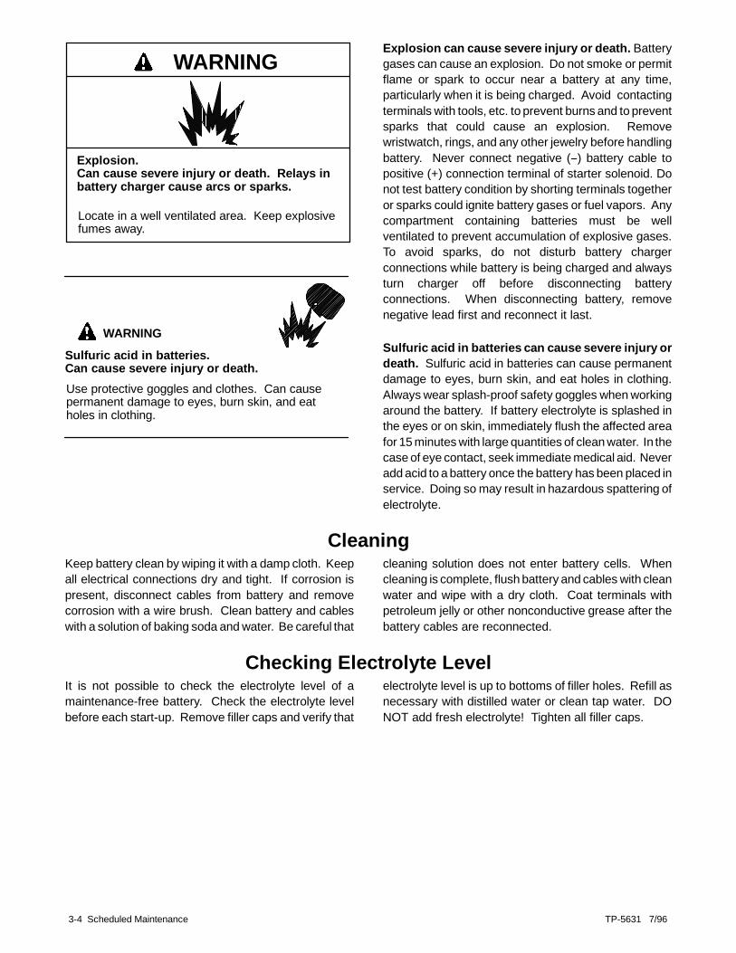
WARNING
Explosion.Can cause severe injury or death. Relays inbattery charger cause arcs or sparks.
Locate in a well ventilated area. Keep explosivefumes away.
WARNING
Sulfuric acid in batteries.Can cause severe injury or death.Use protective goggles and clothes. Can causepermanent damage to eyes, burn skin, and eatholes in clothing.
Explosion can cause severe injury or death. Batterygases can cause an explosion. Do not smoke or permitflame or spark to occur near a battery at any time,particularly when it is being charged. Avoid contactingterminals with tools, etc. to prevent burns and to preventsparks that could cause an explosion. Removewristwatch, rings, and any other jewelry before handlingbattery. Never connect negative (--) battery cable topositive (+) connection terminal of starter solenoid. Donot test battery condition by shorting terminals togetheror sparks could ignite battery gases or fuel vapors. Anycompartment containing batteries must be wellventilated to prevent accumulation of explosive gases.To avoid sparks, do not disturb battery chargerconnections while battery is being charged and alwaysturn charger off before disconnecting batteryconnections. When disconnecting battery, removenegative lead first and reconnect it last.
Sulfuric acid in batteries can cause severe injury ordeath. Sulfuric acid in batteries can cause permanentdamage to eyes, burn skin, and eat holes in clothing.Always wear splash-proof safety goggles when workingaround the battery. If battery electrolyte is splashed inthe eyes or on skin, immediately flush the affected areafor 15 minutes with large quantities of clean water. In thecase of eye contact, seek immediate medical aid. Neveradd acid to a battery once the battery has been placed inservice. Doing so may result in hazardous spattering ofelectrolyte.
CleaningKeep battery clean by wiping it with a damp cloth. Keepall electrical connections dry and tight. If corrosion ispresent, disconnect cables from battery and removecorrosion with a wire brush. Clean battery and cableswith a solution of baking soda and water. Be careful that
cleaning solution does not enter battery cells. Whencleaning is complete, flush battery and cables with cleanwater and wipe with a dry cloth. Coat terminals withpetroleum jelly or other nonconductive grease after thebattery cables are reconnected.
Checking Electrolyte LevelIt is not possible to check the electrolyte level of amaintenance-free battery. Check the electrolyte levelbefore each start-up. Remove filler caps and verify that
electrolyte level is up to bottoms of filler holes. Refill asnecessary with distilled water or clean tap water. DONOT add fresh electrolyte! Tighten all filler caps.

TP-5631 7/96 Scheduled Maintenance 3-5
Checking Specific GravityIt is not possible to check the specific gravity of amaintenance free battery. Use a battery hydrometer tocheck the specific gravity of the electrolyte in eachbattery cell. While holding the hydrometer vertical, readthe number on the glass bulb at the top of the electrolytelevel. Use the correction table in Figure 3-3 if thehydrometer used does not have a correction table.Determine specific gravity and electrolyte temperatureof battery cells. Locate temperature in Figure 3-3 andadjust specific gravity by amount shown. The battery isfully charged if the specific gravity is 1.260 at anelectrolyte temperature of 80°F (26.7°C). Thedifference between specific gravities of each cell shouldnot exceed ±0.01. The battery should be charged if thespecific gravity is below 1.215 at an electrolytetemperature of 80°F (26.7°C).
10
20
30
40
50
60
70
80
90
100
110
120
130
140
150
160
- 12.2
- 6.7
- 1.1
4.4
10
21.1
26.7
32.2
37.8
43.3
48.9
54.4
60.0
65.6
71.1
15.6
+ .032
+ .030
+ .028
+ .026
+ .024
+ .022
+ .020
+ .018
+ .016
+ .014
+ .012
+ .010
+ .008
+ .006
+ .004
+ .002
0
- .002
- .004
-. 006
- .008
- .010
- .012
- .014
- .016
- .018
- .020
- .022
- .024
- .026
- .028
°C °F
EXAMPLE NO. 1Temperature below 80°F(26.7°C)
Hydrometer Reading 1.250Acid Temperature 20°F(-6.7°C)
Subtract .024 Sp. GravityCorrected Sp. Gravity is 1.226
EXAMPLE NO. 2Temperature above 80°F(26.7°C)
Hydrometer Reading 1.235
Acid Temperature 100°F(37.8°C)
Add .008 Sp. GravityCorrected Specific Gravity is1.243
The temperature correction amounts to about .004 (4 points) ofspecific gravity for each 10°F (5.5°C) change in temperature.
Correction
Figure 3-3. Specific Gravity TemperatureCorrection

3-6 Scheduled Maintenance TP-5631 7/96
Generator ServiceHave an authorized service distributor/dealer performall generator set service. Under normal conditions,regular generator service is not required. For operationunder dusty and dirty conditions, use dry compressedair to blow dust out of the generator. Do this with thegenerator set operating and direct the stream of air inthrough the cooling slots at the end of the generator.
Replace the end bracket bearing every 10,000 hours ofoperation in standby and prime power applications.Service more frequently if bearing inspection indicatesexcessive rotor end play or bearing damage fromcorrosion or heat build-up. The end bracket bearing issealed and requires no additional lubrication.
Storage ProcedurePerform the following steps if the generator set is out ofservice for three months or longer.
Engine oil1. Operate generator set for 5 minutes.2. Stop the generator set.3. While the engine is still warm, drain the engine
lubrication oil from the crankcase.4. Refill the engine crankcase with an oil having a
viscosity appropriate for the particular climate.5. Run the generator set for a few minutes to
distribute the clean oil.6. Stop the generator set.
Fuel (gasoline-fueled engines)1. To remove fuel.
a. Drain the fuel from the fuel tank.b. Drain the carburetor bowl (or run generator set
until empty). This prevents the gasoline frombecoming stale.
2. To stabilize fuel.a. Use a gas stabilizer for gasoline-fueled
generator sets in lieu of draining the carburetorbowl. Add fuel stabilizer to the fuel according tothe manufacturer’s instructions.
Fuel (gaseous-fueled engines)1. With the generator set running, shut off the gas
supply.2. Run generator set until the engine stops from lack
of fuel.
Coolant (liquid-cooled models only)1. Check engine coolant protection.
Lubricate Cylinders1. Remove the spark plugs.2. Pour approximately one tablespoon of engine oil
into each spark plug hole.3. Crank the engine two or three revolutions to
lubricate the cylinders.4. Reinstall spark plugs.
Exterior Preparation1. Clean exterior surface of generator set.2. Seal all openings in the engine with non-absorbent
adhesive tape.3. Mask off all areas to be used for electrical contact.4. Spread a light film of oil over unpainted metallic
surfaces to prevent rust and corrosion.

TP-5631 7/96 Troubelshooting 4-1
Section 4. TroubleshootingWhen troubles occur, do not overlook simple causeswhich might seem too obvious to be considered. Astarting problem, for example, could be attributed to anempty fuel tank. As a general aid to diagnosingcommon
problems, refer to the Troubleshooting Table below. Ifthe trouble cannot be corrected through routineservicing, contact an authorized servicedistributor/dealer for assistance.
General Troubleshooting Chart (Sheet 1 of 2)Problem Possible Cause Corrective Action
Generator set willnot crank
Weak or dead battery Recharge or replace; check battery chargeroperation. Check battery charging circuit (circuitbreaker, module, and wiring), if equipped.
Reversed or poor battery connections Check connectionsFuse blown in controller Replace fuseDefective starter/starter solenoid Test functionDefective start/stop switch (master switch) Test functionGenerator master switch in OFF position(attempting start-up from remote switch) *
Move master switch to AUTO position
Generator setcranks but will not
Incorrect fuel Replace fuelGenerator setcranks but will notstart, starts hard,
No fuel Add fuel; check fuel control circuitstart, starts hard,lacks power, or Clogged fuel filter (gasoline models only) Replace fuel filterlacks power, oroperates erratically Air cleaner lever in the wrong temperature position
(6.5 kW models only)Place air cleaner lever in correct position forwinter or summer starting (6.5 kW)
Air cleaner clogged Clean and/or replaceWeak or dead battery Recharge or replaceDefective fuel pump (gasoline models only) Check fuel pump for functionDefective fuel valve or (gas models only) Check fuel valve for functionDefective antidiesel solenoid (gasoline modelsonly) Check antidiesel solenoid for functionDefective carburetor choke (gasoline models only) Check function of carburetor chokeDefective fuel regulator (gas models only) Check function of fuel regulatorFaulty ground (--) connection Clean and tighten ground connectionsFaulty spark plugs Replace (and regap) spark plugsDefective ignition system Check ignition coil, module, and wiringLoose spark plug wire connection Check spark plugs wiresInsufficient fuel pressure (gas models only) Check fuel pressureEngine malfunction Troubleshoot engineDefective cold weather starting aid Check cold weather starting device
Low oil pressure shutdown switchCheck oil level, oil pressure, and check switch forfunction
Carburetor adjustment incorrect Adjust carburetorCarbon build-up on cylinder heads Service cylinder headsIncorrect engine timing (signal) Check air gap of ignition pickup
* 5-light microprocessor controller only.
4-2 Troubleshooting TP-5631 7/96
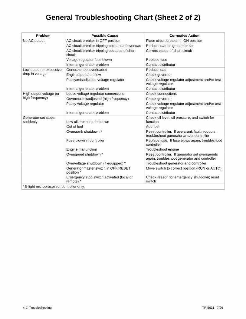
General Troubleshooting Chart (Sheet 2 of 2)
Problem Possible Cause Corrective ActionNo AC output AC circuit breaker in OFF position Place circuit breaker in ON positionNo AC output
AC circuit breaker tripping because of overload Reduce load on generator setAC circuit breaker tripping because of shortcircuit
Correct cause of short circuit
Voltage regulator fuse blown Replace fuseInternal generator problem Contact distributor
Low output or excessivedrop in voltage
Generator set overloaded Reduce loadLow output or excessivedrop in voltage Engine speed too low Check governor
Faulty/misadjusted voltage regulator Check voltage regulator adjustment and/or testvoltage regulator
Internal generator problem Contact distributorHigh output voltage (orhigh frequency)
Loose voltage regulator connections Check connectionsHigh output voltage (orhigh frequency) Governor misadjusted (high frequency) Check governor
Faulty voltage regulator Check voltage regulator adjustment and/or testvoltage regulator
Internal generator problem Contact distributorGenerator set stopssuddenly Low oil pressure shutdown
Check oil level, oil pressure, and switch forfunctionsuddenly
Out of fuel Add fuelOvercrank shutdown * Reset controller. If overcrank fault reoccurs,
troubleshoot generator and/or controllerFuse blown in controller Replace fuse. If fuse blows again, troubleshoot
controllerEngine malfunction Troubleshoot engineOverspeed shutdown * Reset controller. If generator set overspeeds
again, troubleshoot generator and controllerOvervoltage shutdown (if equipped) * Troubleshoot generator and controllerGenerator master switch in OFF/RESETposition *
Move switch to correct position (RUN or AUTO)
Emergency stop switch activated (local orremote) *
Check reason for emergency shutdown; resetswitch
* 5-light microprocessor controller only.

TP-5631 7/96 Generator Reconnection 5-1
Section 5. Generator Reconnection
Voltage Reconnection ProcedureThe reconnection procedure explains voltagereconnections only. If frequency changes are required,the governor and voltage regulator need adjustment.See the generator set service manual for informationregarding frequency adjustment.
To illustrate the reconnection of 4-lead or 12-leadgenerator sets, the following information is provided. Inall cases, follow the National Electrical Code (NEC)guidelines.
Reconnect the stator leads of the generator set if adifferent output phase (12-lead models only) or voltageis desired. Refer to the following procedure and theconnection schematics. Follow all safety precautions atthe front of this manual and in the text while performingthis procedure.
NOTEOrder voltage reconnection decal 246242 from anauthorized service distributor/dealer and affix decal togenerator set after reconnecting to a voltage differentthan the nameplate.
Accidental starting.Can cause severe injury or death.
Disconnect battery cables before working ongenerator set (disconnect negative lead first andreconnect it last).
WARNING
Disabling generator set. Accidental starting cancause severe injury or death. Turn generator setmaster switch to OFF position, disconnect power tobattery charger, and remove battery cables (removenegative lead first and reconnect it last) to disablegenerator set before working on the generator set orconnected equipment. The generator set can bestartedby an automatic transfer switch or remote start/stopswitch unless these precautions are followed.
WARNING
Hazardous voltage. Moving rotor.
Can cause severe injury or death.
Operate generator set only with all guards andelectrical enclosures in place.
Grounding generator set. Hazardous voltage cancause severe injury or death. Electrocution ispossible whenever electricity is present. Open maincircuit breakers of all power sources before servicingequipment. Configure the installation to electricallyground the generator set and electrical circuits when inuse. Never contact electrical leads or appliances whenstanding in water or on wet ground, as the chance ofelectrocution is increased under such conditions.
Short circuits. Hazardous voltage can causesevere injury or death. Short circuits can cause bodilyinjury and/or equipment damage. Do not contactelectrical connections with tools or jewelry whileadjustments are made. Remove wristwatch, rings, andjewelry before servicing equipment.

5-2 Generator Reconnection TP-5631 7/96
Four-Lead (Single-Phase)Generator Sets
NOTECurrent transformers (CTs) are used only on generatorsets equipped with controllers with meters.
NOTEPosition current transformers CT1, CT2, and CT3 withdot or HI side toward generator set.
See Figure 5-1 for four-lead reconnectable(single-phase) generator set options.
60 Hz 50 Hz100-120 volt X100-120/200-240 volt X X200-240 volt X
Figure 5-1. Four-Lead, Single-Phase GeneratorSet Voltage Connection Options
NOTEMicroprocessor controller only: Make fineadjustment ±5% using voltage adjustmentpotentiometer on the controller front panel.
100-120 Volt ConfigurationsThe load side terminals of the circuit breaker are not tobe connected together when a factory two-pole circuitbreaker is used, see Figure 5-2. If the installationrequires a 100-120 volt, 2 wire system, use a single polecircuit breaker. See Figure 5-3. When connectingstator phase leads together, size output lead (L1)accordingly. Use a jumper lead on the line side of thecircuit breaker to balance the load of the generator set.
L0-L1L0-L2
60 Hz100-120 volt100-120 volt
50 Hz100-120 volt100-120 volt
4 3 2 1Stator Leads
LOGRD
LO (Neutral)
Ground
LoadSide
LineSide
FactoryTwo-Poleor (2) 1-PoleCircuitBreakers
JumperLead
L1L2
TP-5631-5
CT1
CT2
UP V7 LOTB2 Meter ScaleLamp Jumper
Figure 5-2. 100-120 volt, 3 wire
4 3 2 1Stator Leads
LO
GRD
LO (Neutral)
Ground
LoadSide
LineSide
1-PoleCircuitBreaker
L1
TP-5631-5
CT1
CT2 not used
UP V7 LOTB2 Meter ScaleLamp Jumper
Figure 5-3. 100-120 volt, 2 wire

TP-5631 7/96 Generator Reconnection 5-3
100-120/200-240 VoltJumper lead not used. If the generator set was originallywired for straight 100-120 volt 3 wire, be sure to removejumper lead. See Figure 5-4 for location of jumper lead.Leads L1 and L2 are of different phases. Never connectLeads L1 and L2 together.
NOTEUse a circuit breaker manufacturer’s two-pole circuitbreaker. Two single-pole circuit breakers do notconform to NEC requirements when supplying a200-240 volt load. This is true even if they aremechanically attached together.
L0-L1L0-L2L1-L2
60 Hz100-120 volt100-120 volt200-240 volt
50 Hz100-120 volt100-120 volt200-240 volt
4 3 2 1Stator Leads
LO
GRD
L2L1
LO (Neutral)
LineSide
FactoryTwo-PoleCircuitBreaker
Ground
LoadSide
TP-5631-5
UP V7 LOTB2 Meter ScaleLamp Jumper
CT1
CT2
Figure 5-4. 100-120/200-240 volt, 3 wireconfigurations
200-240 VoltJumper lead not used. If the generator set was originallywired for straight 100-120 volt, 3 wire, be sure to removejumper lead. See Figure 5-5 for location of jumper lead.
4 3 2 1Stator Leads
LO
GRD
L1
LO (Neutral)
LineSide
Single-PoleCircuitBreaker
Ground
LoadSide
Tape to insulatefrom ground
TP-5631-5
UP V7 LOTB2 Meter ScaleLamp Jumper
CT2 not used
CT1
Figure 5-5. 200-240 volt, 2 wire configurations

5-4 Generator Reconnection TP-5631 7/96
12-Lead (Three-Phase) Generator SetsNOTE
Current transformers (CTs) are used only on generatorsets equipped with controllers with meters.
NOTEPosition current transformers CT1, CT2, and CT3 withdot or HI side toward generator set.
Three-phase, 12-lead generator sets are reconnectableto the voltages and phases shown in Figure 5-6. If thegenerator set is reconnected to obtain a different outputvoltage, voltage regulator voltage adjustments may benecessary to obtain desired voltage.
CT1
L1
7 1012
911
8
CT2
L2
5
2
3
6L0
1 4
60 HZ - 120/240V.- 1PH. 3 WIRE50 HZ - 110/220V.- 1 PH. 3 WIREUSED ON GENERATORS 20-100 KW ONLY
L3
CT33
6
L0
10
7L1
CT3 NOT USED
TB2 METER SCALELAMP JUMPER
60 HZ - 120/240V. - 3PH. 4 WIRE DELTA50 HZ - 110/220V. - 3PH. 4 WIRE DELTA
L2
CT2
8
11
2
5
CT3
L3L1
CT1
6 3 12 9
7
10
1
4
TB2 UP V7 LO METER SCALELAMP JUMPER
60 HZ - 120/240V. OR 120/208V. - 3 PH. 4 WIRE LOW WYE50 HZ - 120/208V. OR 110/190V. - 3 PH. 4 WIRE LOW WYE
UP V7 LO
TB2 UP V7 LO METER SCALELAMP JUMPER
1
4
11
8
CT2
L2
2
5
9
12
CT1
60 HZ - 277/480V. - 3 PH. 3 WIRE HIGH WYE50 HZ - 220/380V. - 3 PH. 4 WIRE HIGH WYE
L1 L2
1
4 5
2
7
10 11
8
L0
12
9
CT3
6
3
L3
CT1 CT2
TB2 UP V7 LO METER SCALELAMP JUMPER
L0
Figure 5-6. Generator Reconnection

TP-5631 7/96 Generator Reconnection 5-5
Reconnection Procedure(Microprocessor Controller only)
1. Place the generator set master switch in theOFF/RESET position.
2. Disconnect engine starting battery, negative (--)lead first. Disconnect power to battery charger (ifequipped).
3. Select desired voltage connection from Figure 5-6.Route leads through current transformers andconnect according to the diagram for desiredphase and voltage.
NOTEPosition current transformers CT1 and CT2(single-phase) or CT1, CT2, and CT3(three-phase) with dot or HI mark toward generatorset. Current transformers are only used ongenerator sets equipped with metered controllers.
NOTE
Equipment Damage! Verify that transfer switch,line circuit breakers, and any other accessoriesusing line voltage are sized for the voltageselected.
NOTESee generator service manual for information onchanging generator frequency.
4. If controller is equipped with meters, removecontroller cover and reposition meter scale lampjumper, if necessary, to match meter scale lampswith desired voltage. See Figure 5-8.
5. The jumper J1 must be in place on the overvoltagecircuit board if the generator set is connected for139/240 or 277/480 volts (3-phase, 4-wire, 60 Hz) ifthe generator set is equipped with the overvoltagekit.
For all other voltages, remove J1 jumper from theovervoltage circuit board. See Figure 5-7 for J1jumper location on the overvoltage circuit board.
6. If the controller is equipped with meters, turn thephase selector switch to the L1-L2 position(1-phase or 3-phase depending on generatorconnection). If the controller is not equipped withmeters, connect a voltmeter across leads L1 andL2.
7. Reconnect generator set engine starting battery,negative (--) lead last.
8. Place the generator master switch in the RUNposition to start the generator set.
9. Check voltmeter for correct voltage. Adjustvoltage if necessary with the voltage adjustmentpotentiometer on the controller front panel. SeeFigure 5-9.
10. Stop generator set after adjustment procedure.
1
TP-5631-5
1. J1 jumperFigure 5-7. Overvoltage Circuit Board

5-6 Generator Reconnection TP-5631 7/96
N
VOC3 C2 C1 CO UP V7F LOW
1
TP-5631-5
1. Lamp jumperFigure 5-8. Meter Scale Lamp Jumper
TP-5631-5
PHPH
1
1. Voltage adjustment potentiometerFigure 5-9. Voltage Adjustment (typical)

TP-5631 7/96 Installation 6-1
Section 6. Installation
GeneralRefer to the Industrial Installation Manual TP-5700 forgeneral information regarding generator set installation.TP-5700 is generic and provides the informationrequired to complete the installation. The informationcontained in this section is specific for the 6.5RMYmodel.
Follow the guidelines presented here and in theIndustrial Installation Manual to plan and install the6.5RMY. Use specifications and drawings providedhere only in initial planning. Use respective specsheets, dimension drawings, and wiring diagrams forinstallation. Contact an authorized servicedistributor/dealer for current information.
Air RequirementsThe generator set requires correct air flow for coolingand combustion. The louvers on the upper portion of theweather housing and the cutouts in the skid provide thecooling and combustion air. Do not block or otherwiseinterfere with the function of these openings. Theheated air is expelled by an Air-Vacä reverse flowcooling system where it is discharged downward and
out of the compartment through the discharge chutelocated near the muffler.
If the generator set is to be mounted indoors, maintainthe air flow shown in the spec sheet. Installappropriately sized vents in the building. An air ductflange kit is available to provide the connection to ductthe heated air to the outside of the building.
WARNING
1
2
3
ADV-5815A-B
1. Weather housing louvers (air inlet)2. Skid cutouts (air inlet)
3. Heated air exhaust
Figure 6-1. Cooling Air Intake and Air Exhaust

6-2 Installation TP-5631 7/96
Exhaust RequirementsThe exhaust muffler is located in a compartment in theskid under the engine end of the generator set. SeeFigure 6-2. The exhaust system is complete forgenerator sets installed outdoors. The screened piececovering the muffler compartment prevents contact withthe hot exhaust system and keeps rodents and otheranimals out.
For generator sets installed inside a building pipeexhaust outside. Use available flexible exhaust kit andduct flange kit. Correctly size any extension added tothe exhaust outlet so it does not affect the maximumallowable back pressure of the engine. Total length andnumber of bends in the exhaust system may have aneffect on the back pressure. Locate the exhaust outletto prevent entry by rodents and birds. Use a rain capwhen the exhaust outlet is directed upward.
ADV-5815C-A
Figure 6-2. Exhaust Muffler Location
Fuel SystemSome generator sets may be equipped with an emissioncertified engine. Emission certified engines may befitted with carburetors that have no possibleadjustments.
The generator set can be fueled by gasoline, LP gas, ornatural gas. Gasoline requires a different fuel systemthan the gas fuels. The gas fuels use the same systembut different fuel regulators. For information on gas fuelconversion, see Section 3, Gaseous Fuel Systems.The fuel inlet connection for gasoline models is a rubberhose with a 1/4 in. (6 mm) ID. The gas fuel models havea fuel line with a 5/8-18 SAE 45°flare female swivelconnector. The rubber hose for all fuels is located nearthe battery compartment on the 6.5 kW. Route this hoseas necessary to reach the fuel supply.
Comply with local and state codes regarding the correctstorage of fuel. Because of the scope of the topicinvolving variable climate conditions and geographicalconsiderations, contact Authorized ServiceDistributor/Dealer for fuel system planning andinstallation. Protect all fuel lines from machinery orequipment contact, adverse weather conditions, andenvironmental damage.
10 AMP
RUNRESET/
OFF AUTO FAULT INPUT
1
ADV-5815B-A
1. Fuel inletFigure 6-3. Fuel Supply Line
(gas-fueled model shown)

TP-5631 7/96 Installation 6-3
Electrical Connections
BatteryThe battery is mounted in a skid compartment locatedon the generator end of the skid. Standard batterycables provide easy connection to the battery. A batteryrack is available to secure the battery if required.Remove the hole plug located on the right side of theskid to connect battery charger cables and any otherbattery connections.
1 2
ADV-5815A-B
1. Positive, red battery connection2. Negative, black battery connection
Figure 1. Battery Connections
Accessory Electrical ConnectionsThere are numerous accessories which can beconnected to the generator set including remoteannunciator, audio-visual alarm, dry contact relay kit,and remote emergency stop switch. See Section 1—Accessories and an authorized servicedistributor/dealer for a list of available accessories.
Most of the accessories operate on 12 volts DC andsome may require AC line voltage. Do notdirect-connect accessories to the controller terminalstrip. Connect all accessories to either a single-relay drycontact kit or ten-relay dry contact kit. Connect the dry
contact kit(s) to the controller terminal strip. Useseparate conduit for AC and DC leads to reduce thepossibility of electrical interference especially with themicroprocessor controller. Verify that leads and conduitdo not interfere with the operation of the generator set orobstruct the service areas. Verify that electricalinstallation complies with the National Electrical Code(NEC) and is done by a licensed electrician. Follow allapplicable local and state codes. See Wiring DiagramsManual for more information regarding generator setelectrical connections.
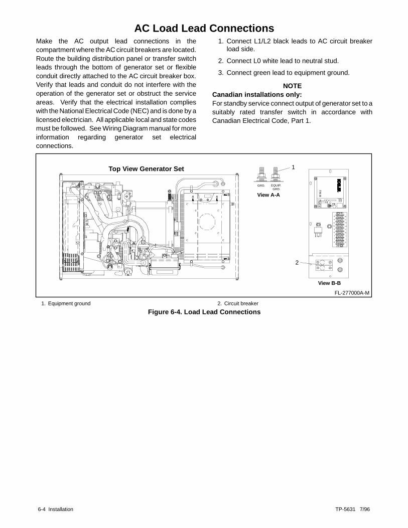
6-4 Installation TP-5631 7/96
AC Load Lead ConnectionsMake the AC output lead connections in thecompartment where the AC circuit breakers are located.Route the building distribution panel or transfer switchleads through the bottom of generator set or flexibleconduit directly attached to the AC circuit breaker box.Verify that leads and conduit do not interfere with theoperation of the generator set or obstruct the serviceareas. Verify that the electrical installation complieswith the National Electrical Code (NEC) and is done by alicensed electrician. All applicable local and state codesmust be followed. See Wiring Diagram manual for moreinformation regarding generator set electricalconnections.
1. Connect L1/L2 black leads to AC circuit breakerload side.
2. Connect L0 white lead to neutral stud.3. Connect green lead to equipment ground.
NOTECanadian installations only:For standby service connect output of generator set to asuitably rated transfer switch in accordance withCanadian Electrical Code, Part 1.
Top View Generator Set
68
67
FP
FN
70
7N
3
4
32
68
R
67
EQUIP.GRD.
GRD.
FP
FN
70
7N
3
4
32
View A-AA BA
B
View B-B
FL-277000A-M
1
2
1. Equipment ground 2. Circuit breakerFigure 6-4. Load Lead Connections

TP-5631 7/96 Appendix A-1
Appendix A. Glossary of AbbreviationsAbbreviations are used throughout this manual.Normally they will appear in the text in complete formwith the abbreviation following in parentheses the firsttime they are used. After that they will appear in the
abbreviated form. The commonly used abbreviationsare shown below. Some items may not apply to thisapplication.
Abbreviation Description Abbreviation DescriptionABDC after bottom dead centerAC alternating currentAISI American Iron and Steel InstituteAHWT anticipatory high water temp.ALOP anticipatory low oil pressureAM amplitude modulationamp ampereamps amperesANSI American National Standard InstituteAPI American Petroleum Instituteapprox. approximate, approximatelyA/R as required, as requestedA/S as supplied, as stated, as suggestedASA American Standards Association
(former name of ANSI)ASME American Society of
Mechanical Engineersassy. assemblyASTM American Society for Testing
MaterialsATDC after dead top centeraux. auxiliaryA/V audio--visualAWG American Wire GageAWM appliance wiring materialBBDC before bottom dead centerBDC before dead centerBHP brake horsepowerbmep brake mean effective powerBTDC before top dead centerBtu British thermal unit_C Celsius degreecc cubic centimeterCCA cold cranking ampsCEC Canadian Electrical Codecfh cubic feet per hourcfm cubic feet per minuteCID cubic inch displacementcm centimeter, centimeterscmm cubic meters per minuteco. companycont’d. continuedCPVC chloropoly vinyl chlorideCRT cathode ray tubeCSA Canadian Standards AssociationCT current transformercu. in. cubic inch (es)
CWC city-water cooledcyl. cylinderdB decibeldBA decibels (A weighted)DC direct currentDCR direct current resistancedeg. degreedept. departmentdia. diameterDIN Deutsches Institut fur Normung e. V.
(also Deutsche IndustrieNormenausschuss)
e.g. example givenEIA Electronic Industries AssociationEMI electromagnetic interferenceEPA Environmental Protection Agencyetc. etcetera, (and so forth)ext. external_F Fahrenheit degreefl. oz. fluid ounce(s)FM frequency modulationft. foot, feetft. lbs. foot pound(s)fs full scalega. gauge (meters wire size)gal./gals. gallon, gallonsgph gallons per hourgpm gallons per minutegr. gradegrd. groundHCHT high cylinder head temperatureHET high exhaust temperatureHg. mercury (element)H2O waterHP horsepowerhr, hrs hour, hoursHWT high water temperatureHz hertz (cycles per second)ID inside diameterIEEE Institute of Electrical and
Electronic Engineersin. inch, inchesinc. incorporatedin. lbs. inch poundsint. internalint.-ext. internal--external

A-2 Appendix TP-5631 7/96
Abbreviation Description Abbreviation DescriptionISO International Standards OrganizationJ joule, joulesJIS Japanese Industry Standardkg kilogram, kilogramskg/cm2 kilograms per square centimeterkgm kilogram meter(s)kJ kilojoules (btu cal)km kilometer, kilometerskPa kiloPascal, kiloPascalskph kilometers per hourkV kilovoltkVA kilovolt ampereskW kilowatt, kilowattskWH kilowatt hourL liter, litersLxWxH length x width x heightLED(s) light emitting diode(s)lb., lbs. pound, poundsL/hr. liter per hour, liters per hourL/min. liter(s) per minuteLOP low oil pressureLP liquified petroleumLWT low water temperaturem meter, metersm3 cubic meter, cubic metersmax. maximumMCM one thousand circular mils.meggar megohmmeterMHz megahertzmi. mile, milesmil one one--thousandth of an inchmin. minimummisc. miscellaneousmJ milli joule(s)MJ mega joule(s)mm millimeterm3/min cubic meters per minuteMPa megaPascalmpg miles per gallonmph miles per hourMS military standardmW milliwatt(s)MW megawatt(s)N/A not availableNBS National Bureau of StandardsN.C. normally closedNEC National Electrical CodeNEMA National Electrical Manufacturers
AssociationNFPA National Fire Protection AssociationNm Newton meter(s)N.O. normally open
no., nos. number, numbersNPT National Standard taper pipe thread
per general useN/R not requiredOC overcrankOD outside diameterOEM original equipment manufacturerOS overspeedO/S oversizeOSHA Occupational Safety and Health ActOV overvoltageoz. ounce, ouncesPF power factorPMG permanent magnet generatorpot potentiometerppm parts per millionpsi pounds per square inchpt., pts. pint, pintsPVC polyvinyl chlorideqt., qts. quart, quartsqty. quantityref. referenceRFI radio frequency interferencer.h.m. round--head machine (screw)rms root means squareRPM revolutions per minuteRTV room temperature vulcanizationSAE Society of Automotive EngineersSCR silicon controlled rectifiersec. second, secondsspec, specs specificationsq. squaresq. cm. square centimeterssq. in. square inch(es)tach tachometerTDC top dead centertech. pub. technical publicationstemp. temperatureTIF telephone influence factorTP, TPs technical publicationsturbo turbochargerUHF ultrahigh frequencyUNC Unified coarse thread (was NC)UNF Unified fine thread (was NF)UL Underwriter’s Laboratories, Inc.U/S undersizeU.S.A. United States of AmericaV volt, voltsvac volts alternating currentvdc volts direct currentVHF very high frequencyW watt, watts

KOHLER CO. Kohler, Wisconsin 53044Phone 414-565-3381Fax 414-459-1646 (U.S.A. Sales), Fax 414-459-1614 (International)For the nearest sales and service outlet in U.S.A. and CanadaPhone 1-800-544-2444PRINTED IN U.S.A.
TP-5631 7/96