operation & maintenance manual · the lifespan of the autoclave will obviously depend upon...
TRANSCRIPT

Operation &Maintenance
ManualTop Loading Direct
Steam HeatedPriorclaves


Priorclave Manual PSQCSEV Issue 1 10/06/03
1
INTRODUCTIONPriorClave autoclaves are a range of general-purpose laboratory autoclaves intendedprimarily for media preparation, the making safe of ordinary laboratory and pathologicalwaste and other apparatus sterilisation purposes. The autoclaves are manufactured to ahigh standard and feature a number of patented innovative design features. Thesophisticated TACTROL microprocessor control system provides a very simple method ofsetting even the most complex cycles. The machines have been designed from the outsetfor easy and safe operation and maintenance.
Properly looked after your autoclave should give years of valuable and trouble free service.
PRIORCLAVE SERVICE
Serial Number:Date of Manufacture:
Software Version:
Please quote the above when asking for parts or service:
PRIORCLAVE LIMITED
129 /131 Nathan WayWest Thamesmead Business Park
LondonSE28 0AB
Telephone: +44 (0)20-8316-6620
Fax: +44 (0)20 8855-0616
E-mail: [email protected]
Website: www.priorclave.co.uk
or your local agent:

2
This Page Has Been Deliberately Left Blank

Priorclave Manual PSQCSEV Issue 1 10/06/03
3
IMPORTANT NOTICES• Priorclave Pressure Vessels and Autoclaves are manufactured according to BS2646
Part 1 (1993). It is recommended that the user/operator ensures that the autoclave isinstalled, operated, maintained and tested according to parts 2,3,4 & 5 of this standardfor safe and effective use and that an adequate logging record of operation andmaintenance be established.
• Before despatch from our works all Priorclaves are subjected to rigorous electricalsafety tests to the appropriate standards. Should you or your contractors carry outfurther insulation and flash tests as part of your internal procedures please disconnectthe switch mode power supply before testing. Failure to do so will result in a test failureand may lead to corruption of the microprocessor memory which cannot be covered byour warranty.
Safety• If you are unclear about any aspects of this manual, the use and operation of the
autoclave or your autoclave process please contact Priorclave or your authorisedPriorclave dealer before proceeding.
• Always wear gloves a facemask and adequate protective clothing when unloading anautoclave and ensure that the workload does not exceed safe limits.
• Priorclave are pleased provide training for operators in the use of their autoclaves at asmall extra charge.
Thermal Lock• The safety Thermal Lock (80oC door retention device) has been set in accordance with
the load and procedure defined in paras. 3.3.3.2.3 and 3.3.3.3 of BS2646 Part 5:1993.
• The relatively light load defined under this procedure may not be appropriate to the loadto be autoclaved in your Priorclave. Therefore, to ensure compliance with Health &Safety Executive Guidance Note PM73 �Safety at Autoclaves� and to avoid possibleinjury you are strongly advised to have your autoclave with its normal working loadformally validated, and the thermal lock set up accordingly by properly trainedpersonnel.
Stainless Steel Pressure Vessels.• Vessels are manufactured from grade 316 stabilised stainless steel, designed built and
tested in accordance with BS5500 category 3 as required by BS2646 Part 1. Grade 316stainless steel is employed to reduce the corrosive effects of substances such ashydroxides and chlorine. However we recommend that the interior of the vessel is keptfree of such potentially harmful substances and is regularly cleaned out with soft water.The use of chlorine based or other aggressive cleaners is not recommended. Exposureto such chemicals could damage the surface finish and the integrity of the pressurevessel and door. Care should also be taken not to routinely introduce such chemicalswhere they are used to pre-wash items that form part of the load. In such cases theitems should be thoroughly rinsed before autoclaving.
Product Life• Due to fatigue occurring in normal use the life of all pressure vessels is finite regardless
of corrosion, erosion or other damage. Using calculations from BS5500, and assumingworking at the maximum working pressure of 2.4 bar this gives the autoclave vessel aprojected fatigue life of 15,000 operating cycles. The lifespan of the autoclave willobviously depend upon frequency of use, but for example (based on a 365 day workingyear) if the autoclave is used two or four times per day this gives a working life of 20.5to 10.2 years respectively. Your own usage of the autoclave should be considered todetermine the actual lifespan of the autoclave.

4
Cleaning• This equipment contains sensitive electrical equipment. Although designed to withstand
laboratory conditions it is not designed for wet cleaning. Cleaning this equipment byhosing down may cause damage, invalidating the warranty, and may cause anelectrocution hazard.
• External cleaning should be carried out with a damp cloth or with proprietary, non-abrasive cleaners.
Servicing and Maintenance of Priorclave Autoclaves• Priorclave Laboratory Autoclaves are complex pressure systems designed and built to
special regulations and as such should only be serviced or maintained by properlytrained personnel. Priorclave Ltd. cannot be held responsible for hazards or damageresulting from work carried out on the pressure system by untrained or unauthorisedpersonnel. If in doubt please contact Priorclave Service or your nearest authoriseddealership.
MarkingThe mark applied to this autoclave is applied in relation to the EMC (ElectromagneticCompatibility) directive and the Low Voltage directive of the European Community. Thisindicates that this Priorclave autoclave meets the following technical standards :
• EN50081-1Electromagnetic Compatibility. Generic Emission Standard. Residential, Commercial & LightIndustry.
• EN50082-1Electromagnetic Compatibility. Generic Immunity Standard. Residential, Commercial & LightIndustry.
• BS EN 61010-1: 1993Safety Requirements for Electrical Equipment for Measurement, Control and Laboratory use.
• BS EN 61010-2-041: 1996Safety Requirements for Electrical Equipment for Measurement, Control and Laboratory use;Part 2-041, Particular Requirements for Autoclaves using Steam for the treatment of MedicalMaterials and for Laboratory Processes.
• EN 46001: 1997If used for the sterilisation of medical equipment within the scope of the Medical DevicesDirective the mark is applicable to this directive. If using this equipment for the sterilisation ofmedical equipment your attention is drawn to the need for the consideration of the standardsthat may be applicable to the type of equipment to be sterilised. If in doubt consult themanufacturer. In all cases autoclaves used for the sterilisation of medical devices must bevalidated in accordance with EN554 before use. This product is manufactured in accordancewith EN46001.
Pressure vessels• PD5500 2000
Unfired fusion welded pressure vessels
• BS2646 1996Autoclaves for sterilisation in laboratories
Conformity assessment modules B1 + D of the European Pressure equipment directivehave been applied to ensure compliance with the essential safety requirements.
A �Declaration of Conformity� in accordance with the above standards has been made andis on file at:
Priorclave Ltd.
129 /131 Nathan Way
West Thamesmead Business ParkLondon SE28 0AB
Priorclave Manual PSQCSEV Issue 1 10/06/03
5
Environmental Conditions
This equipment has been designed for safe operation within the following environmentalconditions:
• Indoor Use.
• Altitude up to 2,000 M. (See Appendix B - Steam Table for special conditions affectingcalibration for operation at elevated altitudes).
• Temperatures between 5oC and 40oC.
• Maximum Relative Humidity of 85% at any temperature between 5oC and 40oC.
• Mains Supply Voltage Variations not exceeding +/-10% of that shown on the SerialPlate.
• Electromagnetic InterferenceThis equipment has been designed to comply with the requirements for immunity fromelectromagnetic interference under normal conditions of use. Care should be takenwhen siting the equipment however, to avoid interference from potential extremesources of interference such as MR scanners or x-ray equipment.
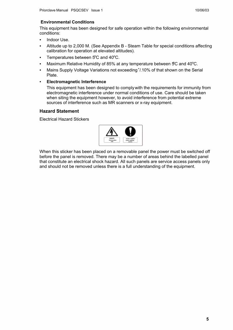
Hazard Statement
Electrical Hazard Stickers
When this sticker has been placed on a removable panel the power must be switched offbefore the panel is removed. There may be a number of areas behind the labelled panelthat constitute an electrical shock hazard. All such panels are service access panels onlyand should not be removed unless there is a full understanding of the equipment.

6
CONTENTSINTRODUCTION ..........................................................................................................................1IMPORTANT NOTICES...............................................................................................................3CONTENTS ..................................................................................................................................6LAYOUT DIAGRAM ....................................................................................................................7OPERATING SUMMARY............................................................................................................8PREPARING YOUR PRIORCLAVE FOR USE FOR THE FIRST TIME ............................. 10
Preparing your Priorclave for use......................................................................................... 10Positioning .............................................................................................................................. 10Installation...............................................................................................................................10Electrical.................................................................................................................................. 10Steam Supply & Connection................................................................................................. 11Drainage ................................................................................................................................. 11Commissioning....................................................................................................................... 13Full Commissioning and Performance Testing.................................................................... 14
CONTROL PANEL LAYOUT................................................................................................... 15OPERATION.............................................................................................................................. 16
Aborting the Cycle.................................................................................................................. 21CHANGING DATE & TIME ...................................................................................................... 22OPERATION WITH OPTIONS & ACCESSORIES ................................................................ 23
Multi Program Memory Options............................................................................................ 23Setting Lock Keyswitch Option............................................................................................. 23Load Sensed Process Timing............................................................................................... 23Printer...................................................................................................................................... 24Chart Recorder....................................................................................................................... 25Internal Validation System..................................................................................................... 25Air Intake Filter ....................................................................................................................... 25Vent Filter................................................................................................................................ 26
VACUUM OPTIONS ................................................................................................................. 26Pre-Cycle Vacuum................................................................................................................. 26Drying Cycle - Suitable for Non Media Loads Only............................................................ 26Vacuum Cooling - Suitable for Non Media Loads Only...................................................... 26
WARNING INDICATORS AND FAULT CODES ................................................................... 28MAINTENANCE ........................................................................................................................ 30
Weekly Maintenance ............................................................................................................. 30Monthly Maintenance............................................................................................................. 31Quarterly Maintenance.......................................................................................................... 31General Maintenance ............................................................................................................ 33
SPARES LIST ........................................................................................................................... 36Specification Tables ............................................................................................................... 39NOTES ....................................................................................................................................... 41APPENDIX A - FAULT FINDING & RECTIFICATION GUIDE ............................................. 43APPENDIX B - STEAM TABLE .............................................................................................. 45APPENDIX C - WIRING DIAGRAMS...................................................................................... 47
Output Board Designations................................................................................................... 47PIPEWORK SCHEMATIC........................................................................................................ 50APPENDIX D - OTHER OPTIONS FITTED ........................................................................... 51

Priorclave Manual PSQCSEV Issue 1 10/06/03
7
LAYOUT DIAGRAM
Tactrol Reset SwitchLocation
Locking Handle
Entry Port AccessPanel Location
1
43
65 7 8 9
101112
2
1. Cycle Progress Display2. Door Button & Indicator3. Vent Button & Indicator4. Start Button & Indicator5. Option Setting Buttons & Indicators6. Temperature Display & Setting Buttons
7. Time Display & Setting Buttons8. Program Buttons & Indicators
(Optional)9. Printer (Optional)10. Setting Lock Keyswitch (Optional)11. Thermal Lock Keyswitch

8
a) Door LockedPosition f) Door unlocked
Positionb) SpringRelease
Safety LockPosition �
WAIT!
c) Unlock
d) Safety LockRelease
e) Push in
Door opening procedure
OPERATING SUMMARYN.B. Before proceeding please check the specification sheet at the front of thismanual to establish which options and accessories, if any, are fitted to yourPriorclave. This will determine whether you will need to read the instructions forthese options later in this manual or in Appendix D.
1) Check electricity and Steam supplies are ON.
Press the �door� button on the control panel there will be a bleep and the message�hoLd� will be displayed in the timer display. Wait for a short time until the timerdisplay returns to normal, there is another bleep and the door indicator illuminates.The door button can now be pressed again to release the lock.
NOTE: Do not pull the handle against the lock before it has released ordamage to the locking solenoid may result.
2) Open the autoclave door as described below:
a) Move the locking handle to the right
b) The handle will now spring out into its unlocking position
c) Move the handle fully to the right to unlock the door. The handle is now in its safetylock position, allowing any residue of pressure inside the autoclave to escapeharmlessly.
d) Move the handle slightly to the right to release it from the safety position
e) Push the handle in as far as it will go
f) Move the handle fully to the right to its parked position
3) With the lid unlocked, carefully lift to the open position.
N.B Take care whilst the door is open that it is fully against its stops and doesnot fall. The door is heavy and could cause harm.
4) Load the autoclave with baskets or containers.
5) Set the temperature as required using the up/down keys.
6) Set the process time as required using the up/down keys.
7) Set / select other functions ie free-steam, rapid cooling etc., as required and if fitted.
8) Carefully lower the pressure lid and secure as follows:
a) Move the locking handle to the left to release it from its parked position
b) The locking handle will now spring out to its locking position
c) Move the locking handle fully to the left to lock the autoclave door
d) Push the handle in fully against the spring

Priorclave Manual PSQCSEV Issue 1 10/06/03
9
e) Move the handle fully to the left into its �park� position
9) Wait a few seconds for the �start� indicator to illuminate, and press the �start� button tobegin the cycle.
Cycle Abort and Thermal Lock OverrideAborting a cycle
To abort the cycle at any stage press the �Start Button�
Thermal Lock Override
First abort the cycle as above. After checking that there is no pressure within the autoclaveturn the thermal lock key to the right hold it there. Press the �Door� button once, keeping thethermal lock key held over. Wait during the �hoLd� display until the �Door� indicatorilluminates. Keep the key held and press the �Door� button once to unlock the door. Thekeyswitch can now be released and the door opened as above. If the key is released atany stage the procedure must be repeated to open the door and reset the display.
e) Door LockedPosition a) Door
unlockedP iti
b) SpringRelease
c) lock
d) Push in
Door closing procedure

10
Isolator Box
Circuit Breakers
Electrical Details - Rear Left ofAutoclave
PREPARING YOUR PRIORCLAVE FOR USE FORTHE FIRST TIME
Preparing your Priorclave for use
Unpack the autoclave and check against the delivery note that all items ordered have beendelivered.
Any shortages or damage must be reported to Priorclave Limited within 7 days of delivery.
Positioning
The autoclave may be positioned flush to units, walls etc. on both sides, but a gap of atleast 204mm (8�) must be left at the back of the machine to allow the door to open fully andto ensure the circulation of air. This will also provide a space for pipework and electricalconnections.
The autoclave has castors fitted at the back to allow easy mounting and positioning andshould ideally be positioned within easy reach of a suitable isolatable electrical supply anddrain (if required). See Installation.
All autoclaves during their process cycle will release steam (unless plumbed into a drain)and heat, and this should be taken into consideration when choosing a site in yourlaboratory in which to install your autoclave.
Installation
Electrical
To connect your Priorclave to the powersupply simply connect a suitable cable fromyour isolator or power socket to the isolatorat the rear of the unit. Wiring is as shown inthe diagram.
The power supply to the Autoclave shouldbe run from a suitably rated isolator or a 13Apower socket (see specification sheet) andconnected to the isolator as in the diagram.Sufficient length of cable should be used toallow the autoclave to be pulled out andworked on from the back. The earth, live andneutral feeds should all be capable of carrying the required amperage. If required theneutral line must be nominally at earth potential, must not be fused and the equipmentmust be earthed.
• 7 kW SINGLE PHASE
Diagram A

Priorclave Manual PSQCSEV Issue 1 10/06/03
11
The power supply to the Autoclave should be run from a suitable 30 Amp isolator andconnected to the isolator as in diagram (A). Sufficient length of cable should be used toallow the autoclave to be pulled out and worked on from the back. The earth, live andneutral feeds should all be capable of carrying 30 Amps. The neutral line must benominally at earth potential, must not be fused and the equipment must be earthed.
NB. Single phase 7 kW machines may be converted at a later date, if required, to 10.5 kW3 phase heating by rewiring as described below.
• 3 PHASE � Liquid Ring Vacuum Pumps
The power supply should be a 3 phase and neutral isolated supply, rated at 15 Amps perphase and connected to the isolator as in diagram (B). Sufficient length of cable should beused to allow the autoclave to be pulled out and worked on from the back. The cable usedto the earth line and neutral feeds should be capable of carrying the per phase amperageof the supply. The neutral line must be nominally at earth potential and must NOT be fused.This equipment must be earthed.
Diagram B
Electrical - General
Heating is by 2, 3 or 6, 3.5 kW immersion elements depending on the heater power of yourautoclave.
The main circuit breakers are located at the back of the autoclave above the mains inlet(see above). The main processor control board is independently fused at its power supply.
See Wiring Diagram - Appendix C - for more details.
Depending on the model and the options fitted to the autoclave one or two 3 pin 230Vpower sockets may be fitted to the back of the autoclave. These are marked with thesymbol shown above are intended for use only with the Priorclave accessory supplied foruse with them which is fitted with the appropriate plug.
Steam Supply & Connection
The autoclave requires a dry saturated steam supply regulated to approximately 40psig,supplied via a 100 mesh strainer. A suitable pressure reducing valve should be providedalong with 2 x 100mm pressure gauges showing regulated and unregulated pressure,these should be located within view of the intended site of the autoclave. A condensatetrap set should be located in the supply within 1m of the connection to the autoclave. Ifrequired for the satisfactory operation of the reducing valve a condensate trap set shouldbe located in the supply to the pressure reducing valve. If a steam quality test port isrequired this should be incorporated into the supply pipework.
A manual isolation valve should be fitted to the steam inlet line (one is supplied with theautoclave).
Drainage
BS2646 Part 2 states that autoclaves used for processing laboratory waste should alwaysbe connected to a drain to prevent contaminated steam and condensate from fouling the

12
laboratory. The drain-pipe should be connected to a sealed drain cover and a high levelvent pipe should be fitted discharging outside the laboratory as in the diagram below.
If possible it is always advisable to connect the autoclave to a drain to cut down on theamount of steam discharged into the laboratory. A compression fitting should beincorporated in the drain-pipe in an easily accessible location to enable easy disconnectionfor maintenance purposes.
An air gap must be left between the drain outlet pipe and drain water level to preventpossible �suck back� of drain water when the autoclave cools.
All drain piping should head downward towards the drain to prevent water collecting in thepipe.
THE SAFETY VALVE OUTLET (MARKED �SAFETY�) MUST NOT BE CONNECTED TOA DRAIN. IT IS A REQUIREMENT OF B.S. AND HEALTH AND SAFETY STANDARDS

Priorclave Manual PSQCSEV Issue 1 10/06/03
13
a) Door LockedPosition f) Door unlocked
Positionb) SpringRelease
Safety LockPosition �
WAIT!
c) Unlock
d) Safety LockRelease
e) Push in
Door opening procedure
THAT A STEAM DISCHARGE MUST BE VISIBLE SHOULD THE SAFETY VALVEOPERATE.
Vacuum Pump
If a vacuum system is to be fitted to your Priorclave the pump is supplied in a separatehousing complete with two flexible connection hoses.
The first hose should be connected between the autoclave and the vacuum pump inlet andsecond from the vacuum pump outlet and the drain.
Drain Condensers
If your Priorclave is fitted with a drain condenser system then this should be connected to asuitable cold water supply and the outlet of the condenser connected to the drain.
Consideration should be given to the discharge from the Vent and Safety Valveoutlets, which should be directed in such a way as to not cause a hazard. This willbe determined by the location of the autoclave.Once properly installed your Priorclave is now ready for use.
Commissioning
Priorclave Autoclaves are given a full operational test before leaving the factory and assuch arrive ready for immediate use after initial installation. It is advisable however to run asimple cycle with the autoclave empty before processing a working load to check that noproblems have arisen during transport.
If commissioning has been ordered with the autoclave this will be carried out by aPriorclave technician otherwise follow this simple procedure to check the operation of yourPriorclave.
2) Check that the power is ON at the wall isolator and that the steam supply is available,at the correct pressure and on.
3) Switch on the power at the isolator at the back of the autoclave (for position seediagrams above). All indicators will light momentarily and a sounder will bleep. Thisenables the indicators to be checked.
4) Press and release the door button, which will bleep, and wait for a short time (about 20seconds) until the door indicator illuminates and the sounder bleeps again. Onpressing the door button a second time, you will hear the locking bolt withdraw.
5) Open the autoclave door as described below:
a) Move the locking handle to the right
b) The handle will now spring out into its unlocking position
c) Move the handle fully to the right to unlock the door. The handle is now in its safetylock position, allowing any residue of pressure inside the autoclave to escapeharmlessly.
d) Move the handle slightly to the right to release it from the safety position

14
e) Push the handle in as far as it will go
f) Move the handle fully to the right to its parked position
6. Set the temperature to 121oC and the process time to 15 minutes using the arrowsunder the displays.
7. Carefully lower the pressure lid and secure as follows:
a) Move the locking handle to the left to release it from its parked position
b) The locking handle will now spring out to its locking position
c) Move the locking handle fully to the left to lock the autoclave door
d) Push the handle in fully against the spring
e) Move the handle fully to the left into its �park� position
8. The start indicator should now be lit.
9. Press the start button to begin the cycle.
10. During the cycle, check that there are no problems during heat-up and process.
Following successful completion of the commissioning cycle your Priorclave is ready toprocess its first working load.
Please refer to the Operation section later in this manual before running your first workingload as this gives further details on operation of the autoclave and on the control optionswhich may be fitted.
If you experience any problems during this procedure please contact Priorclave service oryour local agent.
Full Commissioning and Performance Testing
If you are having the unit commissioned by a Priorclave technician this will be a simplematter of checking for correct installation, checking that all functions are operatingcorrectly, and familiarising you with the autoclave. There are however some benefits thatcan be gained from having your Priorclave commissioned to suit your particular loads andrequirements. Some examples of settings that can be optimised during commissioning, andthe advantages these can provide are listed below.
• Establishing optimum freesteam temperatures for effective air displacement.
• Establishing optimum freesteam time for effective air displacement, whilst eliminatingunnecessary time and energy consumption.
• Establishing optimum process time and temperature to ensure complete sterilisation,whilst maintaining minimum cycle time and energy consumption.
• Setting thermal lock release temperature to suit your particular load, to eliminateunnecessary cooling time whilst ensuring safety.
If you feel that any, or all of the above would be of use to you then please contactPriorclave Service.
e) Door LockedPosition a) Door
unlockedPosition
b) SpringRelease
c) lock
d) Push in
Door closing procedure

Priorclave Manual PSQCSEV Issue 1 10/06/03
15
CONTROL PANEL LAYOUT
12
8
76
5
4
3
2
1
13
18
17
16
15
14
11
10
9
19
21
22
24
23
20
Key
1. Start Button/Indicator2. Pre-Cycle Vacuum Indicator3. Heat Indicators4. Freesteam Indicator5. Heat-up to Process Indicator6. Process Indicator7. Cooling Indicators8. Complete Indicator9. Media Warming Indicator10. Vent Button/Indicator11. Door Button/Indicator12. Freesteam Select Button/Indicator13. Load Sensed Process Timing Select
Button/Indicator (optional)14. Cooling Select Button/Indicator15. Media Warming Select
Button/Indicator16. Vacuum Select Button/Indicator
(optional)17. Temperature Display/Setting18. Timer Display/Setting19. Thermal Lock KeyswitchOptional Fittings20. 5/10 Program Memory
Buttons/Indicators21. Setting Lock Keyswitch22. Printer23. Paper Advance Button24. Printer Door Open Button

16
a) Door LockedPosition f) Door unlocked
Positionb) SpringRelease
Safety LockPosition �
WAIT!
c) Unlock
d) Safety LockRelease
e) Push in
Door opening procedure
OPERATIONBEFORE USING YOUR PRIORCLAVE FOR THE FIRST TIME CHECK THAT THECIRCUIT BREAKERS AND ISOLATOR (AT THE BACK OF THE AUTOCLAVE) ARESWITCHED ON AND THAT THE STEAM SUPPLY IS AVAILABLE, CORRECTLYREGULATED AND CONNECTED.
N.B. Before proceeding please check the specification sheet at the front of this manual toestablish which options and accessories, if any, are fitted to your Priorclave. This willdetermine whether you will need to read the instructions for these options later in thismanual or in Appendix D.
Opening the Door.
1) Switch on the power at the isolator. All indicators will light momentarily and a sounderwill bleep. This is to enable the indicators to be checked. The start indicator shouldnow be lit. Press and release the door button, which will bleep, and wait for a shorttime (about 20 seconds) until the door indicator illuminates and the sounder bleepsagain. During the waiting time the temperature display will show hoLd, confirming thatthe autoclave is waiting during its safety delay. On pressing the door button a secondtime, you may hear the locking bolts withdraw. You may now open the door asdescribed below. (The vent button will light when the door button is pressed andremain lit after the cover is opened.)
NOTE: Do not pull the cover against the lock before it has released or damage tothe locking solenoid may result.
2) Open the autoclave door as follows:
a) Move the locking handle to the right
b) The handle will now spring out into its unlocking position
c) Move the handle fully to the right to unlock the door. The handle is now in its safetylock position, allowing any residue of pressure inside the autoclave to escapeharmlessly.
d) Move the handle slightly to the right to release it from the safety position
e) Push the handle in as far as it will go
f) Move the handle fully to the right to its parked position
NOTE: Care should be taken when opening the lid as it will be hot and steammay be released. Heatproof gloves and a faceshield should always be wornwhen unloading autoclaves.
N.B Take care whilst the door is open that it is fully against its stops and doesnot fall. The door is heavy and could cause harm.

Priorclave Manual PSQCSEV Issue 1 10/06/03
17
3) Loading
The autoclave can now be loaded with the items to be sterilised in either baskets, orwatertight discard containers in the case of waste loads, which may leak liquids whenautoclaved.
Care should be taken when loading the baskets or containers not to pack them tootightly with material. Ample room must be allowed for steam to penetrate the loadproperly or full sterilisation will not be achieved. When using autoclave bags theseshould be left open with the top of the bag rolled outwards, exposing the load to thesteam inside the pressure vessel.
Care should also be taken that the contents of bags and containers are not able to spillover into the body of the autoclave vessel. Any such spillage could block pipes andvalves and will not be covered by the warranty.
N.B. Tests have shown that the depth of unperforated discard containers should be nogreater than 180mm (7�) for effective air displacement from the load. Suitablecontainers are available from Priorclave.
4) Settings.
Once the autoclave has been satisfactorily loaded the controls should be set for theprocess cycle that you require.
If your autoclave has a setting lock fitted this must be set to position 3.
Sterilising Temperature & Time Settings.
The Medical Research Council has recommended the following temperatures andtimes as being sufficient for complete sterilisation in autoclaves:
126oC for 10 minutes.
121oC for 15 minutes.
115oC for 30 minutes.
These temperatures and times relate of course to load temperatures and the aim insetting a cycle should be to achieve one of the above criteria in the coldest part of theload. Some loads however are sensitive to elevated temperatures for prolongedperiods, making full achievement of the above impractical. However the disinfection ofsuch loads after a short cycle, without necessarily reaching full Sterilising Temperature,is usually sufficient for most purposes.
Should you require a more precise method then the optional Load Sensed ProcessTiming may be of assistance for certain load types. If your autoclave is fitted with thisoption please refer to the description later in this manual.
Since there is a time and temperature �lag� between the temperature controller probeand the load, this should be compensated for either by increasing temperature orprocess time, or by including in the cycle a period of free steaming with the vent openat 100oC. This can be achieved by pressing in the vent button manually and releasing itmanually. Alternatively, the Automatic Freesteaming Option will perform this functionautomatically if the option is selected.
If you have an interest in any of the options mentioned above, which can quite easily beretro-fitted, please contact Priorclave Technical Services Department.
In conclusion, when setting up the autoclaving cycle a large safety margin should beallowed within the settings.
More precise settings can be assessed by carrying out a �worst load� test. (Seecommissioning).
5) Setting the process time
The process timer can be set to a time up to 999 minutes. Thetime required is set by simply using the time up/down buttons. Theset time is displayed until the set temperature is reached, then theprocess time begins counting down to zero in increments of oneminute.

18
6) Setting process temperature
Pressing either the up or down button momentarily causes thecurrent set temperature to be displayed. Subsequent use of theup/down buttons changes the set temperature. If no keys arepressed for a short time, the display returns to showing the currentchamber temperature.
7) Selecting other functions
The function select keys may be used to switch the Timed Freesteaming, Cooling,Media Warming Option, and optional functions such as Load Sensed Process Timing,on or off at any time other than when a cycle is running. An indicator illuminates toshow that a function has been selected. If an option is not fitted (or permitted in theselected program in multi-program memory models) pressing the appropriate key willresult in a visual and audible fault being signalled and the function will not be selected.
Automatic Timed Free-Steaming
What is freesteaming?
Incorporating a period of freesteaming into a cycle can improve air removal in difficultloads and/or reduce temperature lag between the load and the autoclave, reducingprocess time at higher temperatures. Freesteaming introduces a stage during heatingup to Process Temperature, when a solenoid valve at the rear of the autoclave isopened for a pre-set time. The valve opens at a factory set temperature of just above100oC and is held open for the time set as detailed below. During this time steam isbeing generated in the chamber in large volumes and this creates turbulence as itpasses through the load before escaping through the valve. It is this turbulence that canassist with air removal.
Setting the freesteam time.
If freesteaming is required this is selected by pressing the freesteam button. Theindicator lights up to show that freesteaming is selected. The time display will now flashindicating that the freesteam time, not the process time, is currently being displayed.The freesteam time can now be set (in minutes) using the up/down buttons. If no furtherchanges are made for a short time the display stops flashing, and reverts to showingprocess time. If you wish to check the freesteam time or make further changes thenfreesteaming should be deselected, then reselected.
Freesteam temperature setting
Timed freesteaming will commence at a temperature slightly above 100oC, which hasbeen set at the time of manufacture. If required, this temperature may be increased byqualified personnel, and the turbulence caused by the escaping steam pressure canfurther assist with air removal. It is desirable however to connect the autoclave to adrain and vent pipe (as described Installation), as the release of pressurised steam intothe laboratory should be avoided.
Performance can be improved even further by fitting the optional pulsed freesteamingsystem.
Rapid Cooling
A powerful fan is fitted into the bodywork of the autoclave to direct cool air over theautoclave vessel.
If selected by using the cooling button, the cooling fan will switch on automaticallyduring the cooling stage of the cycle. There are three possible settings for rapidcooling, and these operate as follows:
Off - No indicators lit.
The cooling fan does not operate at all during the cycle.
Immediate start - Left hand indicator lit. - 1 press of the cooling button.

Priorclave Manual PSQCSEV Issue 1 10/06/03
19
The cooling fan starts as soon as the cooling stage is reached.
Delayed start - Both indicators lit- 2 presses of the cooling button.
The cooling fan starts after the autoclave chamber has cooled to 100oC.This setting is useful when autoclaving some fluid loads, as bringing thecooling fan on at temperatures above 100oC may reduce the chamberpressure too rapidly, causing the load to boil.
In both cases the fan will switch off automatically when the cycle has reached thecomplete stage.
8) Media Warming
If this highly useful feature is selected the autoclave will cool to a factory pre-settemperature of 45oC. The temperature will then cycle between approximately 45o to55oC until the door is opened. This allows, for example, nutrient media to be held as aliquid until it is needed.
9) Closing the pressure door
Once you have set up the cycle parameters lower the autoclave lid, taking great carenot to allow the lid to be dropped into place as this will result in damage to the closuresystem. Then lock the door as follows:
a) Move the locking handle to the left to release it from its parked position
b) The locking handle will now spring out to its locking positionc) Move the locking handle fully to the left to lock the autoclave doord) Push the handle in fully against the springe) Move the handle fully to the left into its �park� position
10) Starting a cycle
Ensure the lid is properly secured and the start indicator is illuminated. To start thecycle press the start button. The first segment of the cycle status indicator bar will
e) Door LockedPosition a) Door
unlockedP iti
b) SpringRelease
c) lock
d) Push in
Door closing procedure
Pre-Cycle Vacuum (if fitted and selected)
Heat-up to freesteam temperature
Freesteaming
Heat-up to process temperature
Cooling
Cycle Complete
Media Warming in operation (if selected)
Process Time

20
illuminate and the autoclave will now gradually heat up to process temperature. Thecycle status indicator will also advance through its stages to give �at a glance� indicationof the cycle�s progress.
11) Once a cycle has been started the function selection settings cannot be changed,attempting to do so will cause a fault to be signalled. If changes are required the cycleshould be aborted by pressing the start button again.
12) On Priorclaves not fitted with the setting lock keyswitch changes can be made to theprocess time and temperature settings once a cycle has started. At the end of the cyclethe time setting will reset to its original setting.
13) Vent button
The vent button may be used at any stage during the cycle. When used it opens alarge bore solenoid vent valve at the back of the machine. It may be left open forfreesteaming to achieve better steam penetration of the load if AutomaticFreesteaming has not been selected. It may also be used with certain loads as ameans of rapidly venting the autoclave. If used for manual freesteaming the vent buttonmust be manually released before pressure will build up and process temperature canbe achieved.
CARE SHOULD BE TAKEN IF USING THE VENT BUTTON WHEN THEAUTOCLAVE IS PRESSURISED. VENTING OF THE AUTOCLAVE UNDER THESECIRCUMSTANCES WITH A LIQUID LOAD MAY LEAD TO THE LOAD BOILINGOVER AND GLASSWARE MAY BE BROKEN.
14) During the process time
Once set temperature is reached, the process time will begin to count down and theprocess indicator will illuminate. If the Load Sensed Process Timing Option is fitted andselected there may be a delay between the autoclave reaching set point andcommencement of the process time whilst the load reaches set temperature.
During the process time a check should be made that there is correct correlationbetween temperature and pressure readings on the control panel. A steam table isincluded at the back of this manual for this purpose. The check should be made toensure that air has been properly purged from the autoclave. Generally, entrapped airin the autoclave will be indicated by a pressure reading higher than would be expected.
If for any reason the temperature is forced outside of a pre-set band, or power to theautoclave is removed during the process time, the cycle will abort and the fault indicatorwill illuminate and a fault code of either F005 or F006 will be shown in the temperatureindicator. This is to ensure that loads which have not been subjected to the requiredcycle parameters are not assumed to have been processed correctly. The faultcondition is cancelled by:
If no setting lock keyswitch is fitted:
pressing the reset button on the top right hand side of the back of the autoclave,
or
If a setting lock is fitted:
turning the setting lock key to the enable position, and then to the disable position. Ifthe lock was in the enable condition when the fault occurred, then it must first be turnedto the disable position.
15) Cooling
After completion of the process time the autoclave moves into the cooling part of itscycle, and this is shown on the cycle status indicator in green. If Air Cooling Systemhas been selected this will be switched on automatically according to the coolingstrategy selected.

Priorclave Manual PSQCSEV Issue 1 10/06/03
21
16) Thermal lock
Under normal circumstances the autoclave cannot be opened until the temperature ofthe load simulator probe, which has a cooling rate assimilated to a 1 litre flask or bottleof fluid, has fallen below 80oC at which point the yellow bar on the cycle status indicatorwill illuminate. The temperature shown by the temperature indicator will be significantlybelow 80oC as this measures the temperature in the open chamber space. Pressing thedoor button before the thermal lock has released causes a fault to be signalled. Thetemperature at which the thermal lock operates is factory set. This can be reset butmust only be done following commissioning by qualified personnel. The thermal lockcan be overridden using the keyswitch on the control panel. The keys for this switch areprovided in this manual.
OVERRIDING THE THERMAL LOCK WILL CAUSE THE MAIN VENT TO OPEN.GREAT CARE SHOULD BE EXERCISED WHEN USING THE KEYSWITCH SINCELIQUID LOADS COULD BOIL OVER IF VENTED AT ELEVATED PRESSURES.
There are circumstances, however when quicker access to the load is required. Whenthis is necessary, first abort the cycle by pressing the start button. Then turn the keyinto its horizontal position and holding it in this position, press the door button and waitwhile the hoLd message is displayed until the door lamp illuminates. Finally press thedoor button to release the door lock. The thermal lock key can now be released. If thekey is released before this stage then the hoLd display will not reset and the autoclavecannot be opened. To reset the display repeat the above procedure and open theautoclave.
Great care should be exercised when using the Thermal Lock Override,especially with liquid loads. Even at temperatures below 100 oC a liquid load insealable glass containers will not be safe. For the above reasons the ThermalLock Override key should be kept in a safe place away from the autoclave, foruse only by responsible personnel.
Under certain cycle abort or failure conditions the thermal safety lock can latchin the locked condition. This is because the control system will always go to thesafest condition if there is any uncertainty about the cycle end circumstances. Toovercome this simply go through the door open or close procedure using thethermal lock override key. Operation will return to normal as soon as the nextcycle is completed satisfactorily
17) Cycle complete
When cooling to the �thermal lock deactivation temperature� is complete, the completeindicator will illuminate, and the autoclave will emit a bleep for a short time (about 10seconds). If the Air Cooling System is selected it will automatically switch off at thispoint. The autoclave is now ready to open and unload.
18) Media Warming
If this has been selected, the autoclave will remain at the pre-set temperature after thecycle is complete, until the door is opened or the cycle otherwise aborted.
19) Opening the autoclave to unload and re-load for the next cycle is simply a repetition ofsteps 1,2 & 3.
Aborting the Cycle
On occasions it may be necessary to abort a cycle before its completion. In order to dothis, simply press the start button.

Changing Date & Time
A number of additional control system settings can be accessed via a “Hidden Menu”.
To access these settings turn & hold the thermal lock key in the override position. Press the time up ordown keys. Release the thermal lock key. 1 is displayed on the temperature display, by default 0 willdisplayed on the time display. The temperature display now shows the number of a list of operatingparameters, the value for the parameter is shown in the time display. Scroll through the list of availableparameters using the temperature up/down keys.
After no keys are pressed for eight seconds the display returns to normal.
The function of these settings is as follows:
Temp.
Display
Time
Display
Function Action
The autoclave can be set for the cycle to start after a pre-programmed delay, forexample to allow a media preparation cycle to complete shortly prior to the start of theworking day. Setting the value of parameter 1 to 1 in the time display switches delayedstart on.
1 0-24 Delayed Start Time Hour + Enter required Start time hour (24hour clock)
2 0-60 Delayed Start time Minute + Enter required Start time minute
3 0/1 Start Delay Select On/Off + 1= ON
0= OFF
* 4 0-999 Print Interval Enter time (minutes)betweenprinting during process time (0=printer disabled)
5 Year Setting Enter Year
6 Month Setting Enter Month
7 Date Setting Enter Day of month
8 Hour Setting Enter Hour(24 Hr Clock)
9 Minute Setting Enter Minute
10 Second Setting Enter Second.
Scroll back up to parameter 1 to confirm the new or current timesettings.
# 11 1-999 Cycle Repeats Enter Number of Cycles Required+ The time is set in real time, therefore the clock has to be correctly set for this to work properly.
After one delayed start operation, delayed start automatically switches off, and the autoclave returnsto normal operation.
# Models fitted with optional Cycle Repeat Facility only
* Models fitted with 5 or 10 Program Memory
Setting marked * are program number related, and therefore should you wish to use different valuesfor these in different programs this can be done by changing the value when the correct program isselected.

Priorclave Manual PSQCSEV Issue 1 10/06/03
23
OPERATION WITH OPTIONS & ACCESSORIESThe following descriptions detail how to operate and gain maximum benefit from theoptions and accessories that may be fitted to your Priorclave.
Multi Program Memory Options
When this option is fitted, five program number keys are provided to the right of the controlpanel, each with two indicators. The indicators on the left are for programs 1 to 5 and thoseon the right for programs 6 to 10. If the Priorclave has been specified with a five programmemory only the first five programs will be active. As each program number is selected, theindicator illuminates and the previously selected indicator is cancelled. Pressing the selectbutton toggles between the two program numbers shown on the button.
When the program memory option is fitted a three-position setting lockkeyswitch is fitted. These setting positions allow different levels of access tosettings as follows.
• Position 1. Only the currently selected program can be run.
Program settings cannot be changed.
• Position 2. All programs can be selected and run.Program settings cannot be changed.
• Position 3. All programs can be selected and run.Program settings can be changed freely.
NOTE: The setting lock key can only be removed in positions 1 and 2.
Programming of settings is the same as with the standard machine, but therequired program number should be selected before setting. The settingsentered can then be recalled for subsequent use by simply reselecting thatprogram number.
Setting Lock Keyswitch Option
Fitted on Priorclaves without program memory to give an optional level of security thiskeyswitch has two settings only, which are equivalent to positions 1 & 3 above. The keycan only be removed in position 1.
Load Sensed Process Timing
Load Sensed Process Timing Function
If this option is fitted, the autoclave will be provided with an additionalthermocouple. This is a PTFE coated stainless steel armoured probe that can bepositioned in the load, ideally in the coolest part. When this option is selected, the
autoclave will heat to the set chamber temperature as normal. However, when the settemperature is reached the process time will not begin to count down until the loadtemperature, as sensed by the additional thermocouple, reaches a temperature just belowthe set chamber temperature. The cycle will then proceed in the usual manner.
Load Sensed Process Timing Purpose
The use of load sensed process timing can greatly assist with the sterilisation of certaintypes of difficult dense loads, such as large baskets of bottle caps, pipette tips or animalfeed, by ensuring that the load reaches set temperature. The system is also very effectivefor bagged plastic waste loads, however as these tend to melt down around the probe,consumption of probes can be high. For this type of use load validation may prove to bemore successful and economical in the long term.

24
Positioning Load Sense Probe
The probe should be positioned in what is anticipated to be the slowest part of the load toheat up, for example the centre of a large densely packed load, or the largest of a group offilled bottles. This is important, as there may be large variations in temperature distributionthroughout the load.
NOTE: Temperature variations can be reduced by the use of timed free steaming.
Load Sense Thermocouples
The load sensed process timing option utilises a thermocouple connected directly to themain processor board.
Replacement thermocouples are available from Priorclave.
See Maintenance - for details on thermocouple replacement.
Printer
The printer if fitted is mounted on the right hand side of the control panel. This provides auseful record of the cycle as well as an indication if any faults have occurred. Theinformation printed is as follows:
USER NAME (if provided at time of ordering)
DEPARTMENT (if provided at time of ordering)
AUTOCLAVE SERIAL NUMBER
DATE
CYCLE NUMBER
PROGRAM NUMBER (if multi-program memory option fitted)
TEMPERATURE AND TIME AT CYCLE START (time is set to G.M.T)
TEMPERATURE AND TIME AT END OF FREESTEAMING
TEMPERATURE AND TIME AT START OF PROCESS TIME
The temperature and time are then recorded at pre-set time intervals, until the end of theprocess time.
TEMPERATURE AND TIME AT END OF PROCESS TIME
TEMPERATURE AND TIME AT CYCLE COMPLETE.
CYCLE PASS/FAIL/ABORT
(Fail means that a fault signal has occurred during the cycle or that the cycle was aborted.See - Warning Indicators)
The above information will be printed in the order listed, allowing the information to be readas it is printed.
At any time pressing the left-hand button on the lower right hand side of the printer canadvance the paper.
REPLACING PRINTER PAPER ROLL
Open the front of the printer by pushing the release catch on the far right of the printer unitto the left. The front of the printer unit will now swing open.. The empty roll can now bepulled from the spindle, and the new roll fitted in its place. The end of the roll should thenbe fed into the slot at the top of the printer mechanism as shown in the diagram.

Priorclave Manual PSQCSEV Issue 1 10/06/03
25
Place the end of the paper roll into the entry slot. It may help to tear the corners off the endof the roll to form an inverted V shape. Next, press the paper feed key on the front of thedoor (to the left of the release catch) and the paper will be drawn through the printer head.
Replacing The Printer Ribbon Cassette
When the printing becomes faint the ribbon cassette will need to be replaced. To do this,open the door and withdraw the end of the paper from the print mechanism. Next hold ontothe front of the printer door with one hand and with the other gently squeeze together thetop and bottom of the printer mechanism cover. Then gently lift the cover while holding thedoor in place. The cover and the outside of the door should now separate giving access tothe printer ribbon cassette. The used cassette can then be removed by pulling up evenlyfrom both ends of the cassette. Before fitting the new cassette take up any slack in theribbon by rotating the take up wheel in the direction indicated on the cassette. The cassettecan then be clipped into place. Any further slack that has developed should now be takenup. Push the two parts of the door together ensuring that they are securely joined and re-fitthe printer roll . With the paper re-threaded and the door closed the printer is ready for use.
Chart Recorder
If fitted, the recorder power input is connected directly to the autoclave in such a way thatthe recorder will only operate during the autoclave cycle, i.e. from the pressing of the startbutton to cycle complete. At this time power to the recorder is cut. Unless otherwisespecified, single channel units record the temperature of a fixed thermocouple probe, andin the case of two channel units the second channel records the temperature of the loadprobe.
For more details on individual recorder function and operation please refer to themanufacturer�s manual supplied with the autoclave.
Internal Validation System
If fitted this system continuously monitors the performance of the temperature reading andcontrol system with reference to an internal reference standard. If any problem is detectedwith the system the autoclave is stopped and a fault is signalled. (See Warning Indicatorsand Fault Codes for details.)
Air Intake Filter
When fitted to the autoclave this system ensures that air drawn into the autoclave duringthe cooling stage of the cycle is first passed through a bacteriological air filter. This filter isfitted at the back of the autoclave.
Paper FeedSlot
Printer Ribbon Cover

26
Vent Filter
When fitted to the autoclave this system passes all autoclave discharge through a filterfitted inside a pressurisable stainless steel housing. At the end of the cycle any unfilteredcondensate from the filter housing is returned to the autoclave. The correct operation andeffectiveness of the filter system should be regularly checked. Please refer to themanufacturers instructions enclosed with this manual.
VACUUM OPTIONSN.B. It is strongly recommended that to achieve optimum performance fromPriorclaves fitted with vacuum options that commissioning and/or load validationtests are carried out by a trained Priorclave engineer. If no particular programs havebeen specified your autoclave will be factory set with the following programs:Program 1: Non vacuum Cycle
Program 2: Pre-Cycle Vacuum and Vacuum CoolingProgram 3: Pre-Cycle Vacuum and Vacuum Drying (if specified)
Pre-Cycle Vacuum
The pre-cycle vacuum is selected using the lower function select key on thecontrol panel. With the left-hand upper indicator lit the Pre-Cycle Vacuum is
selected. With the Pre-Cycle Vacuum selected a vacuum pump will run at the beginning ofthe cycle, removing much of the air from the autoclave and load. At a pre-set level ofvacuum the control system switches off the pump and the normal cycle begins. If set atcommissioning a number of vacuum stages will be performed, with heating stages inbetween. Pre cycle vacuum is essential when autoclaving loads containing densely packedporous material.
Drying Cycle - Suitable for Non Media Loads Only
A drying cycle can be selected by means of the lower function select key. Withthe option selected the lower left-hand lamp will illuminate. When this option is
fitted it can be run along with or separately from a Pre-Cycle Vacuum. With the optionselected, at the end of the process dwell time the water charge is drained under pressurefrom the autoclave, and the autoclave cools to a pre-set temperature. If cooling has beenselected the fan will operate at this stage. When this temperature is reached the fanswitches off, a partial vacuum is drawn and heater mats attached to the outside of thevessel are switched on. This has the effect of evaporating liquid on the load. After a pre-settime air is admitted to the vessel and this process is repeated a number of times. At theend of this stage the autoclave passes immediately to cycle complete.
Note: Post cycle drying must not be selected if the load contains bottled liquids,regardless of how these are contained. All liquids in the load will be evaporated.Sealed containers of liquid will explode. Unexploded containers will be in adangerously unstable condition when removed.
Vacuum Cooling - Suitable for Non Media Loads Only
If fitted along with Vacuum Drying this option must be selected forattachment to a particular program in the control software during
commissioning.
A vacuum cooling cycle can be selected by means of the lower function select key. Withthe option selected the lower left-hand lamp will illuminate. When this option is fitted it canbe run along with or separately from a Pre-Cycle Vacuum. With the option selected, at theend of the process dwell time autoclave vent is opened, and the autoclave cools to a pre-set temperature. If cooling has been selected the fan will operate at this stage. When thistemperature is reached the fan continues to run and a partial vacuum is drawn. This has

Priorclave Manual PSQCSEV Issue 1 10/06/03
27
the effect of evaporating liquid on the load causing it to cool rapidly. After a pre-set time airis admitted to the vessel and this process is repeated a number of times. At the end of thisstage the autoclave passes immediately to cycle complete.
Note: Post cycle vacuum cooling must not be selected if the load contains bottledliquids, regardless of how these are contained. All liquids in the load will beevaporated. Sealed containers of liquid will explode. Unexploded containers will bein a dangerously unstable condition when removed.

Warning Indicators and Fault Codes
On the control panel there are a series of ‘hidden until active’ warning indicators. Some of theseindicators will appear in conjunction with a fault code in the temperature display. The meaning of thesewarnings, why they appear, and what to do when they appear, is as follows.
SERVICE
This means that 500 cycles, or six months have passed since the autoclave was last serviced. Theengineer will cancel the message when the autoclave is serviced.
WATER + FAULT CODE F004
The water level has fallen below the minimum level and must be topped up before the autoclave can berun. The warning will automatically cancel when the door is opened and the water level is topped up. Thelow water condition may have caused a running cycle to abort, and the load may need to be autoclavedagain.
O/HEAT + FAULT CODE F003
If fitted, the heater over-temperature protection thermocouple may have sensed that the heatingelement became too hot. This is probably due to a low water condition, which was not sensed by the lowwater probe. The water level and the condition of the probe (see Maintenance) should be checked beforeattempting to use the autoclave again.
If heater over protection is not fitted then the over heat cut out will only operate under extremeconditions, such as a failure of the temperature control system. The next attempt to run the autoclaveshould be closely observed and if problems persist contact Priorclave Service.
FAULT + FAULT CODES F000, F002, F005, F006, F007, F008, F009, F010 & F011
The fault indicator illuminates under conditions that may invalidate the autoclaving process, and mayresult in the load requiring to be autoclaved again. The fault condition will be triggered by any of thefollowing:
F006 Power to the autoclave being interrupted when a cycle is in the heating or process dwell stage ofthe cycle.
F005 The chamber temperature falling below the set temperature by more than 3oC during the processdwell time.
F002 Failure of the temperature control, display, or load simulator thermocouple.
F000 If your autoclave is fitted with the optional self-validation system, an error in the temperaturemeasurement system is signalled by fault code F000. Usually this would mean that a criticalerror has developed in the temperature measurement system, however, as the detection systemis extremely sensitive it is possible that it may be triggered by fluctuations in the electrical powersupply. If fault code F000 appears it may be cleared by the method described below. If the faultcode will not clear, or continues to re-appear then the user cannot correct the fault. In such acase please contact Priorclave service or your local Priorclave approved service agent.
F007 Vacuum stage timeout (loop break). The autoclave has not achieved the pre-set level of vacuumduring the Pre-cycle vacuum stage during the pre-set time.
F008 Heating stage timeout. The autoclave has not reached process temperature within the Pre-settime.
F009 Vacuum cooling set-point not achieved. The autoclave has not achieved a low enough level ofvacuum during the post cycle vacuum stage (Vacuum Cooling or Drying Cycle)
F010 Air detector input activated. If fitted the air detector system has detected an over pressurecondition symptomatic of excess air remaining in the load.
F011 Printer Timeout / Malfunction. The control system has nor received confirmation from the printerwithin its pre-set timeout.
F012 Door micro-switch fault. If a door micro-switch opens during a cycle this fault code is displayed

F013 Jacket Timeout -If a jacket is fitted it has not reached the required temperature within the Pre-set time. This would indicate a problem with steam supply or inlet or drain valve operation
F014 Jacket Over temperature - If a jacket is fitted the temperature has exceeded the pre-set alarmtemperature
F015 Jacket under temperature - If a jacket is fitted the temperature has fallen below the pre-setoperating temperature band.
F016 Water Fill Timeout - The upper level water probe level has not been reached within the allowedtime for filling and the filling operation has been stopped. This function prevents continuousunsupervised operation of the water fill, which could lead to flooding.
F017 FreeSteam - During Pulsed Fresteaming operation the lower of the two set temperatures has notbeen achieved. The temperature has not fallen sufficiently following the opening of the ventvalve.
LOCK
This warning will light when the thermal lock keyswitch is in the override position.
LOAD + FAULT CODE F001
This warning is activated in the event of the failure of the load sensing thermocouple. If the autoclave isfitted with load sensed process timing, this should be deselected to enable the autoclave to run withoutthis feature. The thermocouple should be replaced as soon as possible. Great care should be taken toensure that loads which would ordinarily be autoclaved with load sensed process timing are adequatelysterilised.
CANCELLING FAULT MESSAGES
The fault messages are cancelled by first correcting the source of the original fault, then turning thesetting lock key switch to position 3. If a key-switch is not fitted they are cancelled by pressing the resetbutton.
If 2 or more faults occur at the same time, the one with the highest priority is displayed. (F000 is thehighest priority and F012 is the lowest.) If a higher priority fault is cleared it will be replaced by the nextactive fault, unless this too is cleared by the same action.

30
MAINTENANCENOTE: Before carrying out any maintenance work check the autoclave for any visualsigns of materials which may be contaminated or damaged. Should any such matterbe apparent contact the relevant person of authority before proceeding.
Do not carry out any work unless you are competent to do so. Items in this sectionmarked with * are those which require a level of competence as incorrectmaintenance or fitting could lead to a safety hazard.
DISCONNECT or ISOLATE the machine from mains power supply and steam supplybefore removing any panels or commencing any maintenance work.
Ensure that any electrically locked doors are open before disconnecting power.
IN THE EVENT OF ANY DIFFICULTY or doubt about any maintenance or serviceprocedure contact Priorclave Limited or your nearest Priorclave approved agent or supplierimmediately.
Weekly Maintenance
• Vessel CleaningCheck exterior of machine and the inside walls of the pressure vessel for generalcleanliness, particularly around operating parts and switchgear. Under no circumstancesshould an abrasive or chemically aggressive cleaner be used on the pressure vessel. Theuse of chlorine or hydroxide based cleaners is not recommended (see notices at thebeginning of this manual).
• Gasket
To prolong the life of the sealing gasket it is advisable to lubricate the sealing faces. This iscarried out with the pressure lid in the open position by applying high melting point greaseto the exposed surfaces of the gasket, after cleaning the gasket and inspecting fordamage. A silicone grease such as high vacuum grease is ideal for this purpose.
• Locking ArmsTo ensure a free action of the locking arms they should be kept lubricated with high meltingpoint grease and free from dirt.
• Safety Valve *The safety valve should be periodically checked for freedom of movement. This can beaccessed by removing the large patch panel on the left-hand side of the autoclave. When
the autoclave is at working pressure, keeping well clear of the safety valve outlet, lift thehand lever and check for a free flow of steam from the outlet pipe. If steam does not flow
Safety Valve
Hand Lever
Left Hand Side of Autoclave

Priorclave Manual PSQCSEV Issue 1 10/06/03
31
the valve should be replaced or serviced by a qualified person immediately. Afterreleasing the lever ensure that the steam flow stops fully.
• Drainage
If the autoclave has been plumbed directly into a drain using flexible tubing, this should bechecked for any signs of blockage, obstruction or damage. Also ensure that both ends ofthe tube are connected as originally intended. Check for any obstruction to the safety valveoutlet, which must remain exposed and unconnected to any form of drainage at all times.
• Steam Inlet ValveCheck the condition, appearance and operation of the steam inlet solenoid valve at theback of the machine.
Monthly MaintenanceTo be carried out in addition to weekly maintenance programme.
• General OperationThe general operation and performance of the autoclave should be observed frequently,and any fault or defect reported or rectified immediately, and entered into the notes sectionof the operating manual. (This will assist a service technician in locating any persistent faultand reporting it to the manufacturer.)
• VACUUM PUMPS (If fitted)The operation of the vacuum pump(s) should be checked regularly. Please refer toenclosed vacuum pump manual for further details.
Quarterly Maintenance
• HINGE *
With the pressure lid in the open position the hinge should be cleaned and lubricated withhigh melting point grease.
• AUTOMATIC AIR PURGE VALVE *
It is advisable to replace the expanding switching element and other sealing partscontained in this unit on a regular basis, in order to prevent build up of foreign matter whichmay impair the operation of the unit. The valve is situated on the left-hand side of theautoclave just below the header ring. To remove the parts for replacement simply unscrewthe top cap of the unit and remove. Re-assemble the unit as per the instructions in therepair kit (available from PriorClave Limited or local agent). Should the top cap proveparticularly tight the complete valve should be removed from the pressure vessel and the
Air Purge Valve
Left Hand Side of Autoclave

32
Steam Trap
Strainer
body gripped in a vice to remove the cap, as excessive localised pressure could damagethe pressure vessel. Care should be taken when refitting the valve to the pressure vesselthat all gaskets etc., are replaced in the correct position and the unit should be checked forleaks when first re-pressurised.
• STEAM TRAP AND STRAINER *The steam trap valve operates in the sameway as the air purge valve described above butusing an element rated at a differenttemperature. The valve and a strainer toprotect it are mounted externally at the back ofthe autoclave. The strainer drain should beemptied periodically and the valve elementserviced as described above.
• Microswitches *
To ensure the reliable operation of the autoclave the internal microswitches, located on thelid located beneath the lid cover, should be regularly cleaned and checked.
To gain access to these switches first remove the top cover with the door open.
To remove the cover; first unscrew and remove the yellow locking handle. Next undo thetwo securing nuts. These are located behind the access slots at the inside top of the cover.Finally carefully pull the cover over the locking handle. Replacement of the cover is thereverse of the above procedure, but care should be taken that the slots in the back end ofthe cover are securely located onto the screws at the back of the door.
First check the condition and operation of the small microswitches on the safety gate andon the lid plate close to the locking solenoid. Next check the condition of the larger doorclosed microswitch. Then close the door and check the position in which it is operating theswitch. If necessary, adjust the position of the switch until correct operation is achieved.
• Locking Solenoid *
With door cover removed, check the locking pin and solenoid for freedom of movement. Ifnecessary the screws should be tightened and the solenoid re-aligned with the pin.
Door Assembly
Locking Lever
Safety GateSafety Gate Microswitch
Door Locked Microswitches
Cover Locating Screws
Locking Solenoid
Door Closed Microswitch

Priorclave Manual PSQCSEV Issue 1 10/06/03
33
• Filters (If fitted)
The condition of air intake filters should be inspected regularly. These filters should besterilised (they can be autoclaved) on a regular basis.* Outlet filters, where fitted should be regularly inspected, sterilised and replaced.Inadequate maintenance could cause a significant biohazard. Please refer to theenclosed manual for the filter system for more details.
General Maintenance
• Removing Side Panels *To remove these panels simply remove the screws from the lower corner of each paneland pull the panel down (taking care it does not fall) until clear of the top panel.
Removing Front Panel *(Access to control components)
Remove the bottom front retaining screws on the autoclave legs at the front. With thesescrews removed, the front panel may now be pulled down and forwards.
• Checking Temperature Control And Pressure Gauge *Should a constant deviation from the values shown in the steam table (appendix B) beapparent in these instruments first follow the relevant procedures in the fault-finding table(appendix A). With all of these possible causes eliminated, proceed to check the gauges asfollows:
Contactor (Heaters)
Main ProcessorBoardDoor SolenoidPower SupplyOutput Board(s)
Power Supply
Cooling Fan
Control Components Layout
Panel Fixing Screws
Door Closed Microswitch - Detail Locking Solenoid & Microswitches - Detail

34
Diagram C
First, place a thermocouple probe connected to a digital thermometer or chart recorder ofknown accuracy onto the Temperature Controller Probe. Then set the machine and runthrough a standard cycle. When the process time has commenced check the readingshown by the temperature display against that of the thermometer or recorder. Shouldthere be a disparity of readings in the order of that previously noted then it is likely that theTemperature Controller is at fault and needs resetting.
If only negligible temperature disparity is apparent, however, and the steam pressure is stillvarying from the expected value by the amount noted previously, then the pressure gaugeis probably faulty and in need of replacement.
N.B. THE PRESSURE GAUGE AND CONTROL SYSTEM FITTED TO PRIORCLAVESARE EXTREMELY RELIABLE INSTRUMENTS AND AS SUCH ARE UNLIKELY TOPRODUCE FALSE READINGS. THEREFORE IT IS MORE LIKELY THAT ANYDEVIATION FROM THE VALUES GIVEN IN THE STEAM TABLE IS CAUSED BYINCORRECT AIR PURGING ETC.
• Fitting A New Lid GasketWhen it becomes necessary to replace the gasket, simply remove the old gasket by pullingit out of the groove in the pressure vessel body.
Using an abrasive pad clean out thegroove and wipe away any residuewith a cloth. Locate the joint in thenew gasket and press this part of thegasket firmly into the part of thegroove closest to the hinge, marked Aon diagram C.
Find the opposite centre line of thegasket and press firmly into the pointmarked B on the diagram, ensure thatthere is an even amount of gasketeach side of points A and B. Pressthe gasket into the points marked C,again ensuring that there is an evenamount of gasket between all 4points.
Press the gasket into the four pointsmarked D. Finally press in theremaining points taking care not to cutthe gasket on the header ring. Once the gasket is fully fitted smear the top surfaces withhigh temperature silicone grease if required, and smooth out any lumps, applying pressurein a circular motion around the gasket.
With the new gasket properly fitted, locking the lid may at first be a little tight. Please notehowever that the gasket will bed downconsiderably when the autoclave is firstused.
• Fitting A New WanderingThermocouple
The autoclave is fitted with twothermocouple entry ports located behindthe large patch panel on the left-handside of the autoclave. The large port isintended for multiple test probes for useduring performance testing and thesmaller port is intended for use with thewandering thermocouple used for LoadSensed Process Timing. To remove the
Di D

Priorclave Manual PSQCSEV Issue 1 10/06/03
35
old thermocouple first unplug it from its connection to the main control board and then undoand remove the compression nut from the fitting (see diagram). Using a suitable bluntinstrument, from the inside of the pressure vessel push out the silicone rubber bung fromthe fitting, and remove it from the thermocouple. Next, insert the new thermocouple, It maybe necessary to re-slit the bung to do this. Place the nut washer and bung in position onthe new thermocouple and re-fit. It is advisable to apply some silicone sealant (such asbath sealant) to the joint to assist sealing. The joint should be checked for leaks when theautoclave is first pressurised. Replacement bungs are available from Priorclave, oralternatively use a No. 21 (large port) or a No. 13 (small port) silicone rubber bung and trimthe top end by about 5mm.
Test Port
Wandering ThermocouplePort
Left Hand Side of Autoclave

36
SPARES LIST
A full selection of spares are available from Priorclave Service or your local Priorclavedealer. Please give your autoclave serial number when ordering parts.
A selection of the more commonly used parts is listed below:
DESCRIPTION PART NUMBER
Gasket ACS/GAS/001
Door Locking Solenoid AQS/LSN/003
Air Purge Valve Element ACS/PVE/005
Condensate Return ValveElement Kit (E)
ACS/PVT/063
Condensate Return Valve ACS/CRV/037
Air Purge Valve (Complete) ACS/PVC/037
15mm (½�) Solenoid Valve(Steam inlet)
MID/VVC/007
Vent Valve Complete ACS/VVC/007

Priorclave Manual PSQCSEV Issue 1 10/06/03
37
Safety Valve - Complete ACS/SVC/008
Pressure Gauge ACS/PGA/009
Thermal Lock Keyswitch ACS/TLK/012
Setting Lock Keyswitch ACS/SLK/001
Output Card TAC/OPT/054
Printer Paper Roll TAC/ROL/053
Printer Ribbon Cassette TAC/RIB/152
Door Lock Microswitch ACS/MSS/025
Door Closed Microswitch AQS/MSS/000

38
Wandering Thermocouple Probe ACS/PRB/039
Air Intake Filter ACS/AFL/039
Pressure Switch MID/PSW/028
Locking Clamp Shim AQS/LCS/002
Hinge Block Shim AQS/HBS/001
Single Pole Circuit Breaker 6A ACS/MCB/001
Small Cable Port Bung ACS/SBG/015
Large Cable Port Bung ACS/SBG/022

Priorclave Manual PSQCSEV Issue 1 10/06/03
39
Specification TablesModel PS/QCS/SV100
General Model Top Loading Priorclave
Capacity 100 Litres
Dimensions Machine (wxd) 660x800mm
Installation AreaRequired (wxd)
660x940mm
Weight Unloaded 195kG
Door 50kG
Pressure Vessel 30kG
Electrical Power Supply Required 230V 50Hz 6A (may varyaccording to options fitted)
Steam Steam Supply Required Dry steam regulated to 40 psi
Water Supply Water Supply Required N/A
Drainage Main Drain Connection 22mm BSP
Secondary DrainConnections
Condensate Return - 15mmBSPOthers -15mm BSP (ifApplicable)
Max. Sound Level Without Vacuum Pump Approx. 30db @ 1M
With Vacuum Pump Approx. 75db @ 1M
Max. Heat EmissionFull Cycle ((10.5h x 5.25p)x0.75)/t)
kW/HourWhere: h = heat-up time (hrs) p = process time (hrs) t = Total cycle* (hrs)* to thermal lock temperature

40
Model PS/QCS/SV150
General Model Top Loading Priorclave
Capacity 150 Litres
Dimensions Machine (wxd) 660x800mm
Installation AreaRequired (wxd)
660x940mm
Weight Unloaded 215kG
Door 50kG
Pressure Vessel 32kG
Electrical Power Supply Required 230V 50Hz 6A (may varyaccording to options fitted)
Steam Steam Supply Required Dry steam regulated to 40 psi
Water Supply Water Supply Required N/A
Drainage Main Drain Connection 22mm BSP
Secondary DrainConnections
Condensate Return - 15mmBSPOthers -15mm BSP (ifApplicable)
Max. Sound Level Without Vacuum Pump Approx. 30db @ 1M
With Vacuum Pump Approx. 75db @ 1M
Max. Heat EmissionFull Cycle ((10.5h x 5.25p)x0.75)/t)
kW/HourWhere: h = heat-up time (hrs) p = process time (hrs) t = Total cycle* (hrs)* to thermal lock temperature

Priorclave Manual PSQCSEV Issue 1 10/06/03
41
NOTES

42
NOTES

Priorclave Manual PSQCSEV Issue 1 10/06/03
43
APPENDIX A - FAULT FINDING & RECTIFICATIONGUIDE
SYMPTOM POSSIBLE CAUSE POSSIBLE SOLUTIONNo Power • Power switched off at
isolator• Circuit Breaker Tripped• Electrical Failure
• Check • Reset and check cause• Call Engineer
Cycle does notcommence when startbutton is pressed (Faultindicator flashes)
• Door is not closedproperly
• Microswitch Failure
• Open & Reclose. CheckLocking Bolt Function
• Check Microswitches
Heating slow or notapparent
• Controller incorrectly set • No steam supply, or
inadequate steampressure.
• Inlet Valve Failure • Fault in control circuit.
• Check setting & reset ifnecessary
• Check Isolator valve isopen.
• Check reducing valvesetting and operation.
• Check supply pressure.• Check and replace if
necessary.• Check all connections
and output boardfunction .
Autoclave does notpressurise
• Vent button in openposition
• Freesteam time notcompleted (if option isfitted)
• Air purge valve failure • Vent Valve stuck open • Safety Valve stuck open • Door incorrectly closed
• Check Vent Indicator• Check Cycle Progress
Indicator Display
• Check and replaceinternal parts or valve.
• Check & Replace ifnecessary
• Check for obstructionson lifting handle.
• Check door position andmicroswitch settings
IncorrectTemperature/PressureCorrelation
• Air not fully purged fromautoclave. Due to :
• Incorrect Load Packing • Faulty Air Purge Valve • Faulty Controller or
Gauge
• Re-Load and re-start
cycle with (more)freesteaming.
• Check & Replace ifnecessary
• Check function andcalibration

44
SYMPTOM POSSIBLE CAUSE POSSIBLE SOLUTIONSafety Valve opening • Temperature set too
high• Output board Failure • Safety Valve Faulty
• Check TemperatureSetting
• Check & Replace ifnecessary.
• Check the lock on thevalve is intact and hasnot been tampered withand that the liftinghandle is notobstructed. Check thepressure shown on thegauge is above 2.2 Bar.If not replace the valve.
Door will not open onceAutoclave has cooled to80oC
• Thermal LockTemperature not yetreached in LoadSimulator
• WAIT. Thermal Lock isset to Load and notChamber temperature.
Door does not open whendoor button is pressed
• Safety delay notcompleted
• Thermal Lock
Temperature not yetreached in loadsimulator
• Faulty Door Solenoid(s) • Thermal Lock
previously overridden
• Wait while �hoLd� isdisplayed in thetemperature display
• Check Cycle Completeindicator is lit on cycleprogress display.
• Check Solenoid andOutput Board Function.Replace if necessary.
• Use thermal lock key toopen door. Normalfunction will return aftera complete cycle hasbeen run.
Fault Indication will notgo out
• Fault not Re-set. (Referto manual for list ofFault Codes)
• Rectify cause of faultand reset withKeyswitch or re-setbutton.
If in any doubt about any of the above procedures do not hesitate to call Priorclave Serviceon 020 8316 6620 or your nearest Priorclave approved service agent.

Priorclave Manual PSQCSEV Issue 1 10/06/03
45
APPENDIX B - STEAM TABLE
Temperature (oC) Pressure (Bar)100 0.00105 0.20110 0.43115 0.69120 0.99121 1.06122 1.13124 1.26126 1.41128 1.56130 1.72132 1.89134 2.07136 2.20
Correct Correlation between Temperature and Pressure showscorrect operation of the autoclave and that air purging issatisfactory.
NB.
This table is accurate at sea level and at moderate altitudes will be sufficientlyaccurate for its intended purpose. However, at higher altitudes the pressuresindicated will be slightly higher than those shown above.

46

Priorclave Manual PSQCSEV Issue 1 10/06/03
47
APPENDIX C - WIRING DIAGRAMS
Output Board Designations
Output Board 1
IN OUT FUNCTION1234
Output Board 2
IN OUT FUNCTION1234

48

Priorclave Manual PSQCSEV Issue 1 10/06/03
49

50
PIPEWORK SCHEMATIC
STEAM HEATED WITH DIAPHRAM VACUUM PUMP
drain
condenstate return
FL1 CT1 NRV1
steam supply
PSV1
SV2
PSW
PTR(option)
PGSV5
VT1
vent
SV4
NRV3
VP
FL3NRV4
SV1
NRV5
vacuum release
issue: A date: 28/03/00 drawn: JC
vessel
file:steam heated with diaphram pump.dwg
(dual pump option)

Priorclave Manual PSQCSEV Issue 1 10/06/03
51
APPENDIX D - OTHER OPTIONS FITTED


a) Door LockedPosition
f) Door unlockedPositionb) Spring
Release
Safety LockPosition �
WAIT!
c) Unlock
d) Safety LockRelease
e) Pushin
Door opening procedure
Opening Instructions
Your Priorclave Autoclave is electrically locked. In order to open it and access the fulloperating instructions it will first be necessary to connect it to a suitable electrical supplyas follows:
To connect your Priorclave to the power supply simply connect a suitable cable from yourisolator to the isolator at the rear of the unit. Wiring for single and three phase supplies isas shown in the diagrams.
Your Priorclave can be wired in one of two electrical configurations depending on the power supplyavailable. If in doubt as to which one applies check your power supply.
• 7 kW SINGLE PHASE
The power supply to the Autoclave should be run from a suitable30 Amp isolator or a 13A power socket (see specification sheet)and connected to the isolator as below. Sufficient length of cableshould be used to allow the autoclave to be pulled out and workedon from the back. The earth, live and neutral feeds should all becapable of carrying 30 Amps. The neutral line must be nominallyat earth potential, must not be fused and the equipment must beearthed.
• 3 PHASE � Liquid Ring Vacuum Pumps
The power supply should be a 3 phase and neutral isolatedsupply, rated at 15 Amps per phase, connected to the isolator.Sufficient length of cable should be used to allow the autoclave tobe pulled out and worked on from the back. The cable used to theearth line and neutral feeds should be capable of carrying the perphase amperage of the supply. The neutral line must be nominallyat earth potential and must NOT be fused. This equipment must beearthed.
After connecting the autoclave to a suitable power supply it can be opened as follows:
1. Check that the power is ON at the wall isolator.
2. Switch on the power at the isolator at the back of the autoclave (for position see diagramsabove). All indicators will light momentarily and a sounder will bleep. This enables the indicatorsto be checked. The low water indicator should now be lit.
3. Press and release the door button, which will bleep, and wait for a short time (about 20seconds) until the door indicator illuminates and the sounder bleeps again. On pressing thedoor button a second time, you will hear the locking bolt withdraw.
4. Open the autoclave door as described below:
g) Move the locking handle to theright
h) The handle will now spring out intoits unlocking position
i) Move the handle fully to the right tounlock the door. The handle is nowin its safety lock position, allowingany residue of pressure inside theautoclave to escape harmlessly.
j) Move the handle slightly to theright to release it from the safetyposition
k) Push the handle in as far as it will go
l) Move the handle fully to the right to its parked position