operation maintenance manual pcm cc08
TRANSCRIPT
OWNER’S OPERATION
and
MAINTENANCE MANUAL
A Division of

Part Number - L510010-07A Printed 06/07
Thank you for your selection of Pleasurecraft (PCM) Marine Power for your boating needs. We welcome you to Team PCM, which puts you in the company of tens of thousands of boaters who have relied on Pleasurecraft inboards as their power of choice for over 20 years.
When you chose PCM, you selected the utmost in premium power for your boating application. Pleasurecraft is the world’s largest manufacturer of gasoline marine inboards, and the clear-cut leader in cutting edge technology. Over the years, we have introduced many breakthrough innovations that quickly became industry standards. The pyramidal exhaust system, light-weight transmission, computerized engine control and the Fuel Control Cell (FCC) are all PCM innovations. No matter which PCM model you purchased, you can be sure it is equipped with the latest in modern technology for added performance and durability.
READ THIS MANUAL THOROUGHLY
Before starting your engine(s), READ THIS MANUAL CAREFULLY AND COMPLETELY. If you do not understand any portion of the manual, contact your Dealer for clarifi cation or assistance. Ask your Dealer for a demonstration of actual starting and operating procedures.
The descriptions and specifi cations contained in this manual were in effect at the time of printing. PCM Engines’ policy of continued improvement reserves the right to change specifi cations or design without notice and without obligation.
This manual will cover the following year of manufacture PCM engines:
Year Model
2007 5.0L MPI
2007 5.7L MPI - EX 343
2007 6.0L MPI - ZR6 390
NOTE: This manual covers 2007, year of manufacture engines, SN 473065 and higher.

1L510010-07A
INTRODUCTION ............................................................................................................................... 3-5Registration Information (Warranty Registration Card is located at the back of this manual) ........................ 33-Year Transferable Limited Warranty ..................................................................................................... 4California Emission Control Warranty Statement ..................................................................................... 5PCM Inboard Marine Engine Manufactured from 2003-2007 General Emissions Warranty Coverage .......... 6Safety Information ................................................................................................................................ 9Replacement Parts ............................................................................................................................... 9Safety Warnings ................................................................................................................................... 9BOATING RESPONSIBILITY ......................................................................................................... 10-12Carbon Monoxide Hazard .................................................................................................................... 10Safe Boating Suggestions ................................................................................................................... 11Water Wisdom .................................................................................................................................... 11Operation and Maintenance ................................................................................................................. 11Rules of the Road ............................................................................................................................... 12ENGINE IDENTIFICATION ............................................................................................................. 13-14Engine Identifi cation ............................................................................................................................ 13Owner Identifi cation and Registration Information .................................................................................. 13Engine Model Identifi cation / Advisory ................................................................................................... 14ELECTRONIC FUEL INJECTION INFORMATION ................................................................................ 15Electronic Fuel Injection System .......................................................................................................... 15OPERATING INSTRUCTIONS ........................................................................................................ 16-20Electronic Speed Control ..................................................................................................................... 16Engine Alarm System .......................................................................................................................... 16Instrumentation ................................................................................................................................... 17Starting Engine (Fuel Injected Engines) ................................................................................................ 18Shifting Transmission .......................................................................................................................... 19Stopping Engine ................................................................................................................................. 20Freezing Temperature Operation .......................................................................................................... 20Operation in High Debris Areas ............................................................................................................ 20PCM Basic Cruise Speed Control System ........................................................................................ 21-22CONDITIONS AFFECTING OPERATION ........................................................................................ 23-24Trim and Weight Distribution ................................................................................................................ 23Boat Bottom ....................................................................................................................................... 23Propeller Selection .............................................................................................................................. 24ENGINE BREAK-IN PERIOD .............................................................................................................. 2525-HOUR ENGINE INSPECTION ........................................................................................................ 26FUEL REQUIREMENTS ..................................................................................................................... 27Gasoline Requirements ....................................................................................................................... 27Gasoline Containing Alcohol ................................................................................................................ 27OIL REQUIREMENTS ........................................................................................................................ 28Engine Oil Recommendations .............................................................................................................. 28Transmission and “V”-Drive Oil Requirements ....................................................................................... 28ENGINE MAINTENANCE ............................................................................................................... 29-55Engine Maintenance ........................................................................................................................... 29Checking Fluid Levels .................................................................................................................... 29-31Lubrication ......................................................................................................................................... 31
TABLE OF CONTENTS

2L510010-07A
Electrical System Relay and Fuse Block ............................................................................................... 32Electrical System Fuses ............................................................................................................. 32Boat’s Ignition Fuse ................................................................................................................... 32Electrical System Wiring and Connectors ...................................................................................... 32Battery .................................................................................................................................... 33Fresh Water Cooling System Sacrifi cial Zinc Anode ......................................................................... 34Checking Coolant Level ............................................................................................................. 35Flushing Cooling System - Sea-Water Section ................................................................................ 36Testing Coolant For Alkalinity ...................................................................................................... 37Draining Fresh-Water Cooling System .......................................................................................... 37Filling Fresh-Water Cooling System .............................................................................................. 38Cleaning Sea-Water Section of Heat Exchanger (Fresh-Water Cooled Applications Only) ....................... 39Fuel System Description ............................................................................................................ 40Fuel Control Cell (FCC) Fuel System ............................................................................................ 40Servicing the FCC ..................................................................................................................... 41Primary Fuel Filter (FCC Clamp-on Canister) ............................................................................. 41-42Servicing Fuel Pre-Filter ............................................................................................................. 43Priming Fuel System ................................................................................................................. 43Flame Arrestor ......................................................................................................................... 43Accessory Drive Belt ............................................................................................................. 44-45Changing Oils .......................................................................................................................... 46Engine Alignment ................................................................................................................. 47-50Engine Maintenance Log ............................................................................................................ 51Maintenance Schedule .......................................................................................................... 52-53Visual Inspection ...................................................................................................................... 54Engine Fluid Capacities ............................................................................................................. 54Transmission Fluid Capacities ..................................................................................................... 54Filter and Accessory Requirements .............................................................................................. 55ENGINE SPECIFICATIONS ................................................................................................... 56-58OUT-OF-SEASON STORAGE ................................................................................................ 59-62Engine Storage ........................................................................................................................ 59Draining Instructions .................................................................................................................. 60Battery Storage ........................................................................................................................ 61Recommissioning After Storage ................................................................................................... 62TROUBLESHOOTING .......................................................................................................... 63-65WATER FLOW DIAGRAMS ................................................................................................... 66-69INSTRUMENTATION WIRING DIAGRAM ..................................................................................... 70LITERATURE .......................................................................................................................... 71FORMS............................................................................................................................... 72-75NOTES ................................................................................................................................... 77WARRANTY/REGISTRATION CARD .
TABLE OF CONTENTS
3L510010-07A
REGISTRATION INFORMATION(Warranty Registration Card is located at the back of this manual)
Shortly after your purchase is registered with PCM, you will be mailed your Warranty Card and a Customer Survey. We appreciate your feedback and encourage you to fi ll out the survey after you have had a chance to run your boat for several weeks. We take this input very seriously, and have implemented many of the ideas our customers have given us through this survey. You may also visit our web site at www. pleasurecraft.com.
Again, thanks for choosing PCM. We sincerely wish you happy days on the water.
INTRODUCTION - 1

INTRODUCTION - 13 Year Transferable Limited Warranty
Pleasurecraft Marine Engine Co. (PCM) warrants its new products to be free from defects in material and workmanship under normal use and service conditions, to the fi rst registered user, and all subsequent user who, in accordance with PCM’s warranty transfer policy, transfers any remaining portion of this warranty coverage within 30 days of any subsequent sale/purchases. All components of PCM products are covered under the PCM Warranty, except for those components that are warranted by PCM’s suppliers. The obligation of PCM hereunder shall be limited to the repair or replacement with new or remanufactured components, at its option, of any product or parts thereof which has failed during the period of warranty and which is demonstrated upon examination to have failed due to defective material and/or workmanship. PCM’s policy is one of continued improvement of its products and PCM hereby reserves the right to improve and change the design and production of any of its products without assuming any obligation to modify products previously manufactured and/or sold.
NO OTHER WARRANTY GIVEN The obligations set forth in the preceding paragraph are PCM’s sole obligation and owner’s exclusive remedy. PCM makes no other express warranty to the extent that any additional warranty may be implied by law, the term of such implied warranty shall be limited to the warranty term stated herein, from the date of delivery of the PCM product to the parties outlined herein. No distributor, dealer, agent or employee of PCM is authorized to grant any other or further warranty or incur any additional warranty obligation on PCM’s behalf, in connection with the sale of its products. Any qualifi cation or restriction contained herein which is prohibited by any law of mandatory application shall be deemed to be deleted herefrom, however, such deletion shall have no effect on the remaining provisions hereof, all of which shall remaining full force and effect.
REMEDIES The obligations of PCM set forth in the fi rst paragraph of this Warranty shall be the exclusive remedy for any breach of Warranty hereunder, and any owner or user’s sole remedy in the event of breach of the warranties which are made by PCM is repair or replacement of the product or any warranted part thereof as set forth herein: with this sole exception, PCM shall not be liable for any direct, or indirect, incidental or consequential damages, including without limitation, any damages for property damage, loss of use or loss of profi ts, loss of income, inconvenience, trailering, towing, haul out, launch and/or any other in and out of water expenses, storage charges, dockage charges, expenses to deliver or pick up the product being warranted to and from the dealer, telephone expenses, lodging expenses, travel expenses, mechanic travel time and mileage, damage caused by any occurrence of an insurable nature, rental of substitute equipment of any type, removal and replacement and/or modifi cation of any boat parts to facilitate repairs, moving of furniture, carpets, cleaning, painting, carpenter work, or re-delivery charges. Some States do not allow limitations on how long an implied warranty lasts, so the above limitations may not apply to you. Some States do not allow the exclusion or limitation of incidental or consequential damages, so the above limitation or exclusion may not apply to you. Any owner or user hereby waives for himself/herself/itself and his/her/its successor and assigns (a) any and all claims for punitive damages, and (b) all claims of negligence or strict liability or both, In no event will PCM’s liability exceed the purchase price of the goods which is actually paid to PCM.
WARRANTY COVERAGE, TERM This Warranty is extended only to the fi rst registered owner or registered user, and all subsequent user who, in accordance with PCM’s warranty transfer policy, transfers any remaining portion of this warranty coverage within 30 days of any subsequent sale/purchases, for the period specifi ed below: All components, other than and those itemized below, are warranted for a period of three (3) years from the date of delivery to the fi rst registered owner or registered user, and all subsequent user who, in accordance with PCM’s warranty transfer policy, transfers any remaining portion of this warranty coverage within 30 days of any subsequent sale/purchases in non-commercial use. In case of commercial use, the term of this Warranty shall be the shorter of (a) a period of six (6) months from the date of delivery to the fi rst registered owner or registered user or (b) the expiration of 200 hours of use. Items not covered under this warranty; (A) Water pump impellers are not covered by this Warranty. (B) Seals, gaskets, O-rings, and other material affected by time are not covered by this Warranty if their effectiveness is reduced by an extended storage period prior to sale or use.
OBTAINING PERFORMANCE UNDER WARRANTY PCM’s warranty registration form should be prepared by your selling dealer, executed by you and the dealer and mailed, by you, to PCM within 30 days after the date of purchase. Upon receipt of the warranty registration form, PCM will issue to you a personalized owner’s registration card which will be mailed directly to you. If the owner’s registration card is not received within eight (8) weeks after the date of purchase, please write PCM at the address below. At the time that a claim for warranty service is made, the owner’s registration card should be presented to the person or entity providing warranty service. Authorized PCM dealers or distributors are entitled to be reimbursed by PCM for some or all of the expense of warranty repairs, thus, service under the terms of this Warranty will be performed by an authorized PCM dealer or distributor without charge for established fl at rate labor or replacement parts, other than items not covered by the Warranty, such as , but not limited to, lubricants, spark plugs, points, and other items which are normally frequently replaced as part of routine maintenance. Charges for additional non-warranty work and/or additional dealer charges for labor relative to warranty work in excess of fl at rate must be paid for by the owner. Prior authorization in writing must be obtained from PCM for any warranty repairs over $50.00 and in all cases where the owner fails to establish the purchase and warranty expiration dates with the owner’s registration card sent upon receipt of the warranty registration form by PCM. While failure to present the owner’s registration card will not prevent you from obtaining coverage hereunder, this Warranty shall not be effective and, therefore, cannot be honored until the product purchase date can be confi rmed by PCM. If the card is lost, communicate with PCM at the address listed below, and, for a processing fee of $10.00, a new owner’s registration card will be issued to you. Any questions concerning service, parts or this Warranty should be directed to your selling dealer. If your dealer is unable to assist or if you relocate or are travelling or need a referral to your nearest dealer contact: Pleasurecraft, P.O. Drawer 369, Little Mountain, SC 29075
FAILURES EXCLUDED FROM WARRANTY This Warranty will not apply to any failure which results from accidents, sinking, fi re, neglect, abuse, or abnormal service or use, such as racing, towing or operation in water of insuffi cient depth, or to any failure resulting from improper installation, improper adjustments, repairs or improper delivery service, or to any failure resulting from the use of parts, fuels, oils or lubricants not suitable for use with the product and/or materials or parts not approved by PCM. This Warranty does not apply to any engine or drive which has been modifi ed, or altered, or repaired in such a manner as, in the opinion of PCM, to affect its stability, reliability or performance. Further, this Warranty will not apply to failure resulting from use of non-recommended lubricants or fuels, failure to follow maintenance or lubrication schedules, failure caused or contributed to by contaminated fuel, failure caused by improper installation or misapplication of the engine or drive, failure resulting from the owner’s or operator’s failure to exercise due or normal care and precaution, or failure of components and/or assemblies that are warranted by PCM suppliers.
OWNER’S RESPONSIBILITYPerformance under this Warranty shall be conditioned upon the fi rst registered owner’s or registered users’s compliance with the following requirements: 1 Owner or user shall verify that the pre-delivery service has been performed, all requested information recorded and that the selling dealer has signed the warranty registration. 2 Owner or user shall promptly mail the warranty registration to PCM after accepting delivery. 3 Owner or user shall follow the instruction in the owner’s manual regarding operation, break-in, lubrication, and fuel. 4 Owner or user shall follow or comply with the maintenance schedule, operation limits, and lay up instruction, as outlined in the owner’s manual.
CHOICE OF LAW This Limited Warranty shall be governed by, and construed and interpreted in accordance with, the laws of the State of Ohio, except only to the extent replaced or precluded by other law of mandatory application.
SPECIAL STATE LEGAL REQUIREMENTS This Warranty gives you specifi c legal rights, and you may also have other rights which vary from State to State. The PCM California Model Years 2003-2008 Emissions Warranty and California Emissions Control Warranty Statement is a separate document included in this Manual. Any questions concerning the Emissions Warranty can be obtained by calling 1-803-345-0050.
5L510010-07A
CALIFORNIA EMISSION CONTROL WARRANTY STATEMENTYOUR WARRANTY RIGHTS AND OBLIGATIONS
The California Air Resources Board and Pleasurecraft Marine Engine Co. (hereinafter “Pleasurecraft”) are pleased to explain the emission control system warranty on your inboard marine engine manufactured from 2003-2007. In California, new inboard engines must be designed, built and equipped to meet the State’s stringent anti-smog standards. Pleasurecraft must warrant the emission control system on your inboard engine for the periods of time listed below provided there has been no abuse, neglect or improper mainte-nance of your inboard engine.
Your emission control system may include parts such as the carburetor or fuel injection system, the ignition system, and catalytic converter. Also included may be hoses, belts, connectors and other emission-related assemblies.
Where a warrantable condition exists, Pleasurecraft will repair your inboard engine at no cost to you, including diagnosis, parts and labor.
MANUFACTURER’S WARRANTY COVERAGE:
Select emission control parts from inboard marine engine manufactured from 2003-2007 are warranted for 2 years.
OWNER’S WARRANTY RESPONSIBILITIES:
- As the inboard engine owner, you are responsible for the performance of the required maintenance listed in your owner’s manual. Pleasurecraft recommends that you retain all receipts covering maintenance on your inboard engine, but Pleasurecraft cannot deny warranty coverage solely for the lack of receipts or your failure to ensure the performance of all scheduled maintenance.
- As the inboard engine owner, you should however be aware that Pleasurecraft may deny you warranty cover-age if your inboard engine or a part has failed due to abuse, neglect, improper maintenance or unapproved modifi cations.
- You are responsible for presenting your inboard engine to a Pleasurecraft distribution center as soon as a problem exists. The warranty repairs will be completed in a reasonable amount of time, not to exceed thirty (30) days.
If you have any questions regarding your warranty rights and responsibilities, you should contact Pleasurecraft at 1-803-345-0050.
INTRODUCTION - 1
6L510010-07A
PLEASURECRAFT MARINE ENGINE CO. 2003-2007 GENERAL EMISSIONS WARRANTY COVERAGE
1. Pleasurecraft Marine Engine Co. (hereinafter referred to as “Pleasurecraft”) warrants to the fi rst owner pur-chasing at retail, and all subsequent owners, of every Pleasurecraft inboard marine engine manufactured from 2003-2007, that the emissions control devices on Pleasurecraft inboard marine engines are free from defects in materials and workmanship when manufactured and will remain so for a period of two (2) years from the date of delivery to the fi rst owner purchasing the engine at retail or from the date the engine is fi rst placed into service for demonstration or any other purpose prior to sale to the fi rst owner purchasing the engine at retail.
2. Pursuant to the California Code of Regulations Title 13, Chapter 9, Article 4.7§ 2445.1, Pleasurecraft warrants that each Pleasurecraft engine is designed, built and equipped to conform with all applicable regulations adopted by the California Air Resources Board pursuant to its authority in Chapters 1 and 2, Part 5, Division 26 of the Health and Safety Code, and is free from defects in materials and workmanship that cause the failure of a warranted part to be identical in all material respects to that part as described in Pleasurecraft’s application for certifi cation.
3. Any part covered under this Warranty that is not scheduled for replacement as required maintenance, in the written instructions to be found within the Pleasurecraft Owners/Operators Manual, is warranted for the period of two (2) years. If the part fails during the period of warranty coverage, Pleasurecraft will repair or replace the defective part at any Pleasurecraft warranty station. The repair or replacement will be per-formed at no charge to the owner. Any such part repaired or replaced under this Warranty will be warranted for the remainder of the two (2) year period.
4. Any part covered under this Warranty that is scheduled only for regular inspection in the written instructions to be found within the Pleasurecraft Owners/Operators Manual, is warranted for the period of two (2) years. If the part fails during the period of warranty coverage, Pleasurecraft will repair or replace the defective part at any Pleasurecraft warranty station. The repair or replacement will be performed at no charge to the owner. Any such part repaired or replaced under this Warranty will be warranted for the remainder of the two (2) year period.
5. Any part covered under this Warranty that is scheduled for replacement as required maintenance in the written instructions to be found within the Pleasurecraft Owners/Operators Manual will be warranted for the period of time before the fi rst scheduled replacement date for that part. If the part fails before the fi rst scheduled replacement, Pleasurecraft will repair or replace the defective part at any Pleasurecraft warranty station. The repair or replacement will be performed at no charge to the owner. Any such part repaired or replaced under this Warranty will be warranted for the remainder of the period prior to the fi rst scheduled replacement date for the part.
6. Replacement of any part under this Warranty with a Pleasurecraft supplied part, will not shorten nor extend the warranty period(s) stated in paragraphs one (1) thru four (4) above.
7. The engine owner will not be charged for diagnostic labor that is directly associated with diagnosis of a defec-tive, emission-related warranted part, provided that such diagnostic work is performed at a Pleasurecraft warranty station.
INTRODUCTION - 1
7L510010-07A
INTRODUCTION - 18. To insure prompt repair under this Warranty, Pleasurecraft will maintain a supply of warranted parts suf-
fi cient to meet the expected demand for such parts. Any replacement part may be used in the performance of any warranty maintenance or repairs and will be provided by Pleasurecraft without charge to the owner.
9. Parts covered under this Warranty are: spark plugs, spark advance/retard system, ignition coil and/or con-trol module, ignition wires, PCV valve, oil fi ller cap, intake valve(s), intake manifold, exhaust manifold, exhaust valve(s) hoses, clamps, fi ttings, tubing, sealing gaskets or devices, and mounting hardware, pul-leys, belts and idlers, temperature check, and valves and switches, and electronic controls.
10. Exclusions: The repair or replacement of any warranted part otherwise eligible for coverage under this Warranty may be excluded from such warranty coverage if Pleasurecraft demonstrates that the engine and/or part has been abused, neglected, or improperly maintained, and that such abuse, neglect, or improper maintenance was the direct cause of the need for repair or replacement of the part.
11. Pleasurecraft original equipment parts are “identical in all material respects to that part as described in the engine manufacturer’s application for certifi cation”. The use of any replacement parts not supplied by Pleasurecraft may not meet this requirement and will be grounds for disallowing a claim made under this Warranty. Pleasurecraft will not be liable under this Warranty or provide warranty coverage for product failures caused by parts other than Pleasurecraft original equipment parts.
12. If you have any questions regarding your warranty rights and responsibilities, or the location of Pleasurecraft warranty stations near you, you should contact Pleasurecraft at 1-803-345-0050.

8L510010-07A
This Page Was
Intentionally
Left Blank
INTRODUCTION - 1

9L510010-07A
SAFETY INFORMATION
“Safety Warnings” and additional information or instructions are used to alert the installer/operator of possible safety hazards in performing certain service or maintenance procedures incorrectly or carelessly. DANGERS and WARNINGS are accompanied by the international HAZARD symbol:
These “Safety Warnings” alone cannot eliminate the hazards that they signal. Strict compliance with these warning instructions while performing service and maintenance procedures, plus “common sense” operation, are major accident prevention measures.
REPLACEMENT PARTS
Use of replacement parts (i.e. automotive, after-market, etc.) in the electrical, ignition and fuel systems, which are not U.S. Coast Guard approved, could cause a fi re or explosion hazard and should be avoided.
Always request that genuine PCM Engines replacement parts be used in any repairs or maintenance being performed on your engine(s).
DANGER
Electrical, ignition and fuel system components are designed and manufactured to comply with U.S. Coast Guard rules and regulations to minimize the possibility of fi re or explosion hazard.
DANGER
Signals serious damage, failure or breakdown of equipment; severe injury or high probability of death to the user if proper precautions are not taken. This signal word is applied in extreme situations
SAFETY WARNINGS
WARNING
Indicates a potential hazard which could result in personal injury.
CAUTION
Indicates a hazard which could result in damage to equipment.
WARRANTY NOTICE: Indicates a possible warranty exclusion.
INTRODUCTION - 1
IMPORTANT: or IMPORTANT: Used to provide information to perform a procedure more easily.

10L510010-07A
BOATING RESPONSIBILITIES - 2CARBON MONOXIDE HAZARD
Carbon monoxide is produced when anything that contains carbon, such as gasoline, natural gas, oil, propane, coal or wood is burned. Carbon monoxide is commonly found in the exhaust of internal combustion engines (boat power plants, generators, etc.). In addition, open fl ame devices like cooking ranges, heaters and charcoal grills also produce carbon monoxide.
Carbon monoxide accumulation, in and around boats is affected by vessel geometry; overall vessel design; closeness to other structures; wind direction; boat speed; and many other variables. In no way can this section cover all of the possible variables. Do not rely on this section as the exclusive listing of measures to prevent the accumulation of carbon monoxide.
Consult your boat operators manual for detailed information on the inspection and/or maintenance of the exhaust system for your particular application. If an inspection reveals possible leaks, DO NOT operate your engine(s) until it can be serviced by a qualifi ed technician.
Proper and adequate air circulation, around and throughout the boat, is absolutely necessary to aid in the prevention of carbon monoxide build-up. If you have any questions or concerns regarding the operation of your boat and carbon monoxide hazards, DO NOT operate your engines until you have contacted your boat manufacturer.
DANGER
Carbon Monoxide (CO) is a colorless, odorless and tasteless gas. You cannot see it, smell it or taste it. Prolonged exposure to carbon monoxide can lead to unconsciousness, brain damage or death!
To fi nd out more about making boating safer, including how you can prevent carbon monoxide poisoning on recreational boats, contact:
National Marine Manufacturers Association200 East Randolph Drive
Suite 5100Chicago, IL 60601-6528
www.nmma.org312-946-6200
United States Coast GuardOffi ce of Boating Safety
CG Headquarters G-OPB-32100 Second Street SWWashington, DC 20593www.uscgboating.org
202-267-0984
American Boat & Yacht Council, Inc.3069 Solomon’s Island RoadEdgewater, MD 21037-1416
www.abyc.com410-956-1050
11L510010-07A
BOATING RESPONSIBILITIES - 2SAFE BOATING SUGGESTIONS
The nation’s waterways are becoming increasingly crowded and, in order to enjoy them safely, the operator should acquaint himself/herself with safe boating practices. Boating safely and seamanship courses are offered by the following national and state organizations:
• Power Squadrons • Coast Guard Auxiliary • Red Cross • State, provincial or local agencies in charge of water safety enforcement
PCM Engines highly recommends that all power boat operators attend one of these courses. To help locate a course being offered near you, contact Boat U.S. Foundation’s toll-free national boating safety hotline, 1-800-336-BOAT, and in Virginia, 1-800-245-BOAT.
WATER WISDOM
The following are suggestions for safe operation of your boat to ensure the safety of yourself and your passengers:
• Know your boat’s loading and operating limitations. DO NOT OVERLOAD!
• Make periodic checks of safety equipment onboard.
• Do not consume alcoholic beverages or take illegal drugs when operating a boat. Some state laws apply to boats as well as motor vehicles.
• File a “fl oat plan.” Let someone know your destination and your expected time of return.
• Monitor the weather. Know the signs of weather change and avoid severe weather and rough seas whenever possible.
• Follow the “Rules of the Road” when boating. Always be on the alert and watch out for “the other guy.”
• Plan and chart your course. Be aware of, and avoid, hazardous areas.
• Be sure your boat is equipped with the required safety equipment. Check with the Coast Guard and local government agencies as to the regulations and restrictions in your area. Contact your local Coast Guard Auxiliary and take advantage of their seasonal boat inspections.
The following is a list of suggested safety equipment and spare parts which may be useful in case of an emergency:
• Approved personal fl otation devices (life jackets); one for each person on board.
• Approved throwable personal fl otation device for man-overboard protection.
• Approved fi re extinguishers. • Signal devices: fl ares, spotlight, signal fl ag and
horn or whistle. • PCM Engines’ “Onboard Kit,” plus spare fuses,
bulbs, batteries, etc. Tools necessary for minor repairs.
• Spare propeller. • Anchor and anchor line. • First aid kit and fi rst aid book. • Ship-to-shore radio, compass and chart of the
area in which you are traveling. • Manual bilge pump and spare drain plugs. • Waterproof storage containers.
OPERATION AND MAINTENANCE
It is the owner’s/operator’s responsibility to perform all safety checks before operating his/her boat. All lubrication and maintenance schedules must be adhered to assure optimum performance and dependability from your PCM engine. When service and maintenance are required, return to your authorized PCM Engine Dealer.
12L510010-07A
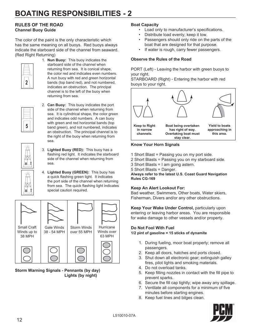
RULES OF THE ROADChannel Buoy Guide
The color of the paint is the only characteristic which has the same meaning on all buoys. Red buoys always indicate the starboard side of the channel from seaward. (Red Right Returning) 1. Nun Buoy: This buoy indicates the
starboard side of the channel when returning from sea. It is conical shape, the color red and indicates even numbers. A nun buoy with red and green horizontal bands (top band red), and not numbered, indicates an obstruction. The principal channel is to the left of the buoy when returning from sea.
2. Can Buoy: This buoy indicates the port side of the channel when returning from sea. It is cylindrical shape, the color green and indicates odd numbers. A can buoy with green and red horizontal bands (top band green), and not numbered, indicates an obstruction. The principal channel is to the right of the buoy when returning from sea.
3. Lighted Buoy (RED): This buoy has a fl ashing red light. It indicates the starboard side of the channel when returning from sea.
4. Lighted Buoy (GREEN): This buoy has a quick fl ashing green light. It indicates the port side of the channel when returning from sea. The quick fl ashing light indicates special caution required.
BOATING RESPONSIBILITIES - 2Boat Capacity • Load only to manufacturer’s specifi cations. • Distribute load evenly; keep it low. • Passengers should only ride on the parts of the
boat that are designed for that purpose. • If water is rough, carry fewer passengers.
Observe the Rules of the Road
PORT (Left) - Leaving the harbor with green buoys to your right.STARBOARD (Right) - Entering the harbor with red buoys to your right.
Know Your Horn Signals
1 Short Blast = Passing you on my port side.2 Short Blasts = Passing you on my starboard side.3 Short Blasts = I am going astern.5 Short Blasts = Danger.Always refer to the latest U.S. Coast Guard Navigation Rules CG-169
Keep An Alert Lookout For:Bad weather, Swimmers, Other boats, Water skiers, Fisherman, Divers and/or any other obstructions.
Keep Your Wake Under Control, particularly upon entering or leaving harbor areas. You are responsible for wake damage to other vessels and/or property.
Do Not Fool With Fuel1/2 pint of gasoline = 15 sticks of dynamite
1. During fueling, moor boat properly; remove all passengers.
2. Keep all doors, hatches and ports closed. 3. Shut down all electronic gear; extinguish galley
fi res, pilot lights and smoking materials. 4. Do not overload tanks. 5. Keep fi lling nozzles in contact with the fi ll pipe to
prevent sparks. 6. Secure the fi ll cap tightly; wipe away any spillage. 7. Ventilate all components for a minimum of fi ve
minutes before starting engines. 8. Keep fuel lines and bilges clean.
2
5
Small Craft Winds up to
38 MPH
Gale Winds 38 - 54 MPH
Storm Winds over 55 MPH
Hurricane Winds over
63 MPH
Storm Warning Signals - Pennants (by day) Lights (by night)
Keep to Right in narrow channels.
Boat being overtaken has right of way.
Overtaking boat must stay clear.
Yield to boats approaching in
this area.

13L510010-07A
ENGINE IDENTIFICATION - 3ENGINE IDENTIFICATION
When ordering service parts or obtaining information, always give the engine model and the serial number. This information can be found on the following decal.
Figure 3-2 Engine Identifi cation Tag Locations (5.0/5.7L)
MAKE
MODEL SERIAL
FIRING ORDER
THIS ENGINE CONFORMS TO ALLAPPLICABLE U.S.GOVERNMENT STANDARDS FOR MARINE ENGINESIN EFFECT AT DATE OF MANUFACTURE.
LITTLE MOUNTAIN, SC 29075
Figure 3-1 Engine Identifi cation Decal
PORT STARBOARD Engine Model Number:
Serial Number(s):
Gear Model Number:
Serial Number(s):
Boat Make:
Boat Model:
Hull Serial Number:
Propeller Size:
Ignition Key Number:
OWNER IDENTIFICATION AND REGISTRATION INFORMATION
We suggest that you record the following information for quick reference when ordering parts or requesting service or warranty.
MAKEMODEL SERIALFIRING ORDERTHIS ENGINE CONFORMS TO ALL APPLICABLE U.S.GOVERNMENT STANDARDS FOR MARINE ENGINESIN EFFECT AT DATE OF MANUFACTURE.
LITTLE MOUNTAIN, SC 29075
1. ENGINE SPECIFICATION DECAL
2. ENGINE IDENTIFICATION DECAL
3. TRANSMISSIONIDENTIFICATION PLATE
3
2
2
1
OIL TYPE:DEXRON III
HIGHWAY 76 EASTLITTLE MOUNTAINS.C. 29075
SERIAL NoMODEL
MARINE POWER
RATIO
CHECK OIL LEVEL DAILYOIL CHANGE AFTER FIRST 25 HOURS OFOPERATION AND EVERY 100 HOURS OR 12MONTHS, WHICHEVER OCCURS FIRST.IMPORTANT NOTE: WARRANTY IS VOID IFMAINTENANCE AND LUBRICATION INSTRUCTIONSPER PCM MANUAL ARE NOT FOLLOWED.
PCM

14L510010-07A
ENGINE IDENTIFICATION - 3
PCMENGINE MODEL IDENTIFICATION / ADVISORY
MODEL 0 2 - 6 0 0 V - 0 1 SERIAL 470000
*SERIAL NUMBER I.D.*1st DIGIT INDICATES DECADE ENGINE WAS MANUFACTURED ( 3 = 1990, 4 = 2000, 5 = 2010 )2nd DIGIT INDICATES YEAR ENGINE WAS MANUFACTURED.
1st - 2nd Space: MANUFACTURING CODE
3rd - 5th Space: ENGINE CODE 810 = 8.1L (496 CID MPI) (GM) 811 = 8.1L (496 CID H.O. MPI) (GM) 600 = 6.0L (364 CID MPI) (GM) 570 = 5.7L (350 CID LH MPI) (GM) 571 = 5.7L (350 CID RH MPI) (GM) 572 = 5.7L (350 CID LH Carburetor) (GM) 573 = 5.7L (350 CID RH Carburetor) (GM) 500 = 5.0L (305 CID LH MPI) (GM) 501 = 5.0L (305 CID RH MPI) (GM) 502 = 5.0L (305 CID LH Carburetor) (GM) 503 = 5.0L (305 CID RH Carburetor) (GM)
6th Space: DRIVE CONFIGURATION blank - Direct Drive V - V-Drive
7th - 8th Space: SPECIFICATION CODE

15L510010-07A
ELECTRONIC FUEL INJECTION INFORMATION - 4ELECTRONIC FUEL INJECTION SYSTEM
The PCM Engines covered in this manual are equipped with an Electronic Fuel Injection (EFI) system, which allows precise control of fuel and spark delivery. The fuel system components of the EFI system are: • The electric fuel pumps • The throttle body assembly • The fuel injectorsThe fuel injection system is controlled by an Electronic Control Module (ECM). The ECM is the decision center of the system. The ECM constantly monitors information from various sensors on the engine, and electronically processes the information, in order to control ignition timing and fuel delivery for optimum performance and fuel economy. The ECM incorporates an engine overspeed protection, calibrated to a specifi c RPM, to prevent engine damage from over-revving.The sensors that the ECM monitors are: • Engine Coolant Temperature (ECT) Sensor • Throttle Position (TP) Sensor • Manifold Absolute Pressure (MAP) Sensor • Knock Sensor (KS) System • Crankshaft Positioning (CKP) Sensor • Camshaft Positioning (CMP) Sensor • Intake Air Temperature (IAT) Sensor • Throttle Control Position (TCP) SensorIf, for any reason, one or more of these sensors or associated wiring malfunctions, the ECM’s built-in self-diagnostic system sets a trouble code and turns on the “MIL” Malfunction Indicator Lamp or “Check Engine” lamp (if equipped) to alert the operator of a malfunction.In most cases, when the “MIL” or “Check Engine” light is on, the engine(s) may lose some performance and/or effi ciency, but remain running adequately. Also, the light may go out or become intermittent, but a trouble code will be logged for future diagnosis.In any case, the operator must obtain service by an authorized PCM dealer to determine the exact cause of the malfunction.

16L510010-07A
OPERATING INSTRUCTIONS - 5ELECTRONIC SPEED CONTROL (IF EQUIPPED)
This engine is equipped with a Digital Throttle Control (DTC) system. The system uses a throttle cable connected between the throttle handle and a Throttle Control Positioning (TCP) sensor located on the engine. The Throttle Control Positioning sensor provides throttle position information to the engine management system which, in turn, electronically controls engine throttle movement.
This boat may also be equipped with an electronic speed control system for skiing, wake boarding, or cruise control. When the boat is operated in a speed control mode, the operator may not have full control of the throttle until the speed control system is deactivated.
Example: If the speed control system is engaged at 32 mph, the throttle handle may be “dead” when trying to accelerate above 32 mph. The speed control system would need to be disengaged, then the operator will gain full control of the boat speed.
Refer to your Boat Manufacturers Owners/Operation manual for specifi c operation and troubleshooting information for your speed control system.
ENGINE ALARM SYSTEM (OPTIONAL)
The PCM engine electronic system is programmed to control the engine alarm system. This system utilizes an indicator lamp (“MIL” or “Check Engine”) and/or an optional audible alarm to warn the operator of possible engine problems.The alarm circuit has a “self” checking feature programmed into the system. This feature will momentarily light the “MIL”, and if equipped, sound the alarm for two short pulses upon initial start-up of the engine.If the “MIL” lights and/or the alarm sounds during operation, observe the instrument panel readings for the possible source of the malfunction, such as low oil pressure or excessive engine temperature readings. Other conditions that may sound the warning buzzer are a transmission over-temperature warning (if equipped), exhaust gas over-temperature warning (if equipped), and for an electronic throttle malfunction.IMPORTANT: A failure involving the Electronic Throttle may result in Idle only operation of the engine. The operator must obtain service by an authorized PCM dealer to determine the exact cause of this malfunction as soon as possible.In most cases, when the “MIL” light is on, the engine may lose some performance and/or effi ciency, but remain running adequately. Also, the light may go out or become intermittent, but a trouble code will be logged for future diagnosis.In any case, the operator must obtain service by an authorized PCM dealer to determine the exact cause of the malfunction.NOTICE: Some boat builders may install their own alarm system. It is recommended that the boat owner check with his or her boat dealer for an explanation of the particular alarm system upon initial delivery.
17L510010-07A
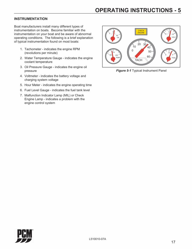
INSTRUMENTATION
Boat manufacturers install many different types of instrumentation on boats. Become familiar with the instrumentation on your boat and be aware of abnormal operating conditions. The following is a brief explanation of typical instrumentation found on most boats:
1. Tachometer - indicates the engine RPM (revolutions per minute)
2. Water Temperature Gauge - indicates the engine coolant temperature
3. Oil Pressure Gauge - indicates the engine oil pressure
4. Voltmeter - indicates the battery voltage and charging system voltage
5. Hour Meter - indicates the engine operating time 6. Fuel Level Gauge - indicates the fuel tank level 7. Malfunction Indicator Lamp (MIL) or Check
Engine Lamp - indicates a problem with the engine control system
OPERATING INSTRUCTIONS - 5
CHECK
ENGINE
TACH
0
1020 30
60
50
40
E
FUEL
1/2
F
TEMP
200
170
100
80
400
OIL VOLT
10 16
13
Figure 5-1 Typical Instrument Panel

18L510010-07A
STARTING ENGINE (FUEL INJECTED ENGINES)
WARNING
Before starting engine, ventilate the engine compartment by operating the bilge blower for a minimum of fi ve minutes to remove any gas fumes from the engine compartment. If the boat is not equipped with a blower, open the engine compartment hatches to ventilate and leave open while starting engine.
OPERATING INSTRUCTIONS - 5
5. Do not pump or open the throttle when starting the engine (Figure 5-3). The ECM will automatically regulate the fuel and control desired idle speed.
6. Turn the ignition key to the start position. When the engine starts, release the key.
NOTICE: Engine idle speed is controlled by the ECM and is based on the operating temperature of the engine. Upon initial start-up, engine RPM will be slightly higher and will automatically decrease as the engine operating temperature increases. 7. In the event the engine becomes fl ooded,
ensure the Neutral Lockout is engaged and move the throttle lever to a 100% open position (Figure 5-3). At this throttle position, the ECM will command the injectors to deliver no fuel during engine cranking. When the engine starts, return the throttle lever back to the idle position.
NOTICE: Single lever throttle/shift handles use different mechanisms to achieve Neutral Lockout or throttle only operation. Some require you to push in on a button while moving the handle forward, others require the button to be pulled out. Refer to your boat owners manual for complete instructions on throttle/shift lever operation.IMPORTANT: If the engine fails to start within 20-30 seconds, turn the ignition key to the OFF position and allow 2 minutes for the starter motor to cool off before attempting to restart the engine.
IMPORTANT: Do not start the engine without water being supplied to the sea water pick-up pump or sea-water pump impeller will be damaged, and subsequent overheating damage to the engine may result.IMPORTANT: The following items should be checked before starting the engine, and each time the boat is operated: • Fuel system for any signs of leakage • Operation of remote controls and steering • Engine and transmission oil levels • Fuel tank levels • Exhaust system for leaks and tightness of the
clamps • Battery connections and water level in battery
cells • Accessory drive belt(s) • Cooling system for leaks. If equipped with fresh-
water cooling, check coolant level in recovery bottle. Check for signs of water leaks at the exhaust manifolds, risers and elbows (Figure 5-2). If the water is leaking externally, it is possible that the water is also leaking internally. This could result in internal engine damage. It is very important to service these maintenance items as soon as a problem is indicated. After performing the initial safety checks, proceed as follows to start the engine:
1. Turn the battery switch ON (if equipped). 2. Open the fuel valve. 3. Open the seacock. 4. Place the remote control in Neutral position. The
transmission is equipped with a neutral safety switch, which will not allow the starter motor to operate unless the transmission is in neutral.
Figure 5-2 Water Leaks
Check forsigns ofexternal leaks
Check forsigns ofexternal leaks

19L510010-07A
Figure 5-3 Typical Throttle / Shift Position Settings
OPERATING INSTRUCTIONS - 5
NOTICE: If engine still fails to start, contact your PCM Engines Dealer for service. 8. Check engine oil pressure immediately after
the engine starts. If oil pressure is not within specifi cations (see Engine Specifi cations), immediately stop the engine and determine the cause.
9. Check voltmeter for proper charging system operation.
10. Check the engine and transmission for fuel, oil, water and exhaust leaks.
11. Allow the engine to reach normal operating temperature. Check the temperature gauge to ensure the engine is operating within the normal temperature range. If the temperature is abnormally high, stop the engine immediately and determine the cause.
SHIFTING TRANSMISSION
CAUTION
Never shift the transmission into or out of gear unless the throttle is at the idle position. Shifting the transmission above 1000 RPM can severely damage the boat, transmission and engine.
1. Set the throttle lever at the idle position. 2. Pull up on the Safety Collar and slowly push the
throttle/shift handle into the Forward gear Idle position.
Throttle may be increased/decreased as required in the Forward Throttle Range. 3. Pull up on the Safety Collar and slowly pull the
throttle/shift handle back into the Reverse gear Idle position.
Throttle may be increased/decreased as required in the Reverse Throttle Range. 4. Move the transmission lever to the center detent
position to shift into Neutral.
NEUTRALFORWARD SHIFTRANGE
IDLE IDLE
REVERSE SHIFT RANGE
FORWARDTHROTTLERANGE
REVERSETHROTTLERANGE
NEUTRALLOCKOUT
SAFETYCOLLAR
FULLTHROTTLE
FULLTHROTTLE
20L510010-07A
STOPPING ENGINE
When returning to the dock, or whenever stopping the engine, bring the throttle back to the idle position and the transmission to Neutral. After the engine reaches idle speed, turn the ignition key to the OFF position.
Before stopping the engine after extended high speed operation, allow the engine to idle at 1200 RPM for 3 to 5 minutes to allow the engine to cool down before shutting off the ignition.
After stopping the engine, complete the following:
1. Turn the battery switch OFF, if equipped.
2. Close the fuel valve.
3. Close the seacock.
4. Flush the cooling system if in a salt water area.
OPERATING INSTRUCTIONS - 5FREEZING TEMPERATURE OPERATION
If the possibility of freezing exists, the cooling system must be protected after the engine is shut off to prevent freeze damage to the engine. Refer to OUT-OF-SEASON STORAGE for draining instructions.
OPERATION IN HIGH DEBRIS AREAS
If the boat is to be operated in high debris areas, a sea strainer should be installed in the water inlet hose to prevent debris from entering the cooling system. The strainer used must be of suffi cient size to allow an adequate supply of water for cooling the engine. A minimum of 30 gallons per minute (114 liters per minute) fl ow rate is required.
21L510010-07A
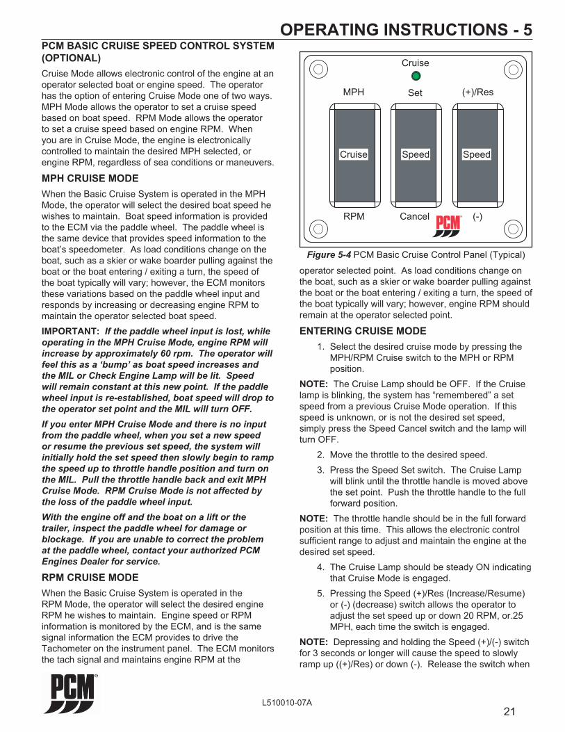
OPERATING INSTRUCTIONS - 5PCM BASIC CRUISE SPEED CONTROL SYSTEM (OPTIONAL)Cruise Mode allows electronic control of the engine at an operator selected boat or engine speed. The operator has the option of entering Cruise Mode one of two ways. MPH Mode allows the operator to set a cruise speed based on boat speed. RPM Mode allows the operator to set a cruise speed based on engine RPM. When you are in Cruise Mode, the engine is electronically controlled to maintain the desired MPH selected, or engine RPM, regardless of sea conditions or maneuvers.
MPH CRUISE MODEWhen the Basic Cruise System is operated in the MPH Mode, the operator will select the desired boat speed he wishes to maintain. Boat speed information is provided to the ECM via the paddle wheel. The paddle wheel is the same device that provides speed information to the boat’s speedometer. As load conditions change on the boat, such as a skier or wake boarder pulling against the boat or the boat entering / exiting a turn, the speed of the boat typically will vary; however, the ECM monitors these variations based on the paddle wheel input and responds by increasing or decreasing engine RPM to maintain the operator selected boat speed.IMPORTANT: If the paddle wheel input is lost, while operating in the MPH Cruise Mode, engine RPM will increase by approximately 60 rpm. The operator will feel this as a ‘bump’ as boat speed increases and the MIL or Check Engine Lamp will be lit. Speed will remain constant at this new point. If the paddle wheel input is re-established, boat speed will drop to the operator set point and the MIL will turn OFF. If you enter MPH Cruise Mode and there is no input from the paddle wheel, when you set a new speed or resume the previous set speed, the system will initially hold the set speed then slowly begin to ramp the speed up to throttle handle position and turn on the MIL. Pull the throttle handle back and exit MPH Cruise Mode. RPM Cruise Mode is not affected by the loss of the paddle wheel input.With the engine off and the boat on a lift or the trailer, inspect the paddle wheel for damage or blockage. If you are unable to correct the problem at the paddle wheel, contact your authorized PCM Engines Dealer for service.
RPM CRUISE MODEWhen the Basic Cruise System is operated in the RPM Mode, the operator will select the desired engine RPM he wishes to maintain. Engine speed or RPM information is monitored by the ECM, and is the same signal information the ECM provides to drive the Tachometer on the instrument panel. The ECM monitors the tach signal and maintains engine RPM at the
Figure 5-4 PCM Basic Cruise Control Panel (Typical)
operator selected point. As load conditions change on the boat, such as a skier or wake boarder pulling against the boat or the boat entering / exiting a turn, the speed of the boat typically will vary; however, engine RPM should remain at the operator selected point.
ENTERING CRUISE MODE 1. Select the desired cruise mode by pressing the
MPH/RPM Cruise switch to the MPH or RPM position.
NOTE: The Cruise Lamp should be OFF. If the Cruise lamp is blinking, the system has “remembered” a set speed from a previous Cruise Mode operation. If this speed is unknown, or is not the desired set speed, simply press the Speed Cancel switch and the lamp will turn OFF. 2. Move the throttle to the desired speed. 3. Press the Speed Set switch. The Cruise Lamp
will blink until the throttle handle is moved above the set point. Push the throttle handle to the full forward position.
NOTE: The throttle handle should be in the full forward position at this time. This allows the electronic control suffi cient range to adjust and maintain the engine at the desired set speed. 4. The Cruise Lamp should be steady ON indicating
that Cruise Mode is engaged. 5. Pressing the Speed (+)/Res (Increase/Resume)
or (-) (decrease) switch allows the operator to adjust the set speed up or down 20 RPM, or.25 MPH, each time the switch is engaged.
NOTE: Depressing and holding the Speed (+)/(-) switch for 3 seconds or longer will cause the speed to slowly ramp up ((+)/Res) or down (-). Release the switch when
deepS
lecnaC
teS
esiurC
MPR
HPM seR/)+(
deepS
esiurC
)-(
22L510010-07A
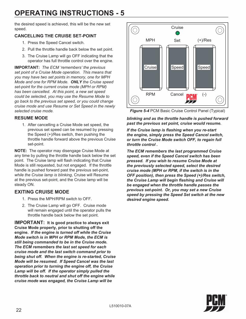
OPERATING INSTRUCTIONS - 5the desired speed is achieved, this will be the new set speed.
CANCELLING THE CRUISE SET-POINT 1. Press the Speed Cancel switch. 2. Pull the throttle handle back below the set point. 3. The Cruise Lamp will go OFF indicating that the
operator has full throttle control over the engine.IMPORTANT: The ECM ‘remembers’ the previous set point of a Cruise Mode operation. This means that you may have two set points in memory, one for MPH Mode and one for RPM Mode. ONLY the Cruise speed set-point for the current cruise mode (MPH or RPM) has been cancelled. At this point, a new set speed could be selected, you may use the Resume Mode to go back to the previous set speed, or you could change cruise mode and use Resume or Set Speed in the newly selected cruise mode.
RESUME MODE 1. After cancelling a Cruise Mode set speed, the
previous set speed can be resumed by pressing the Speed (+)/Res switch, then pushing the throttle handle forward above the previous Cruise set-point.
NOTE: The operator may disengage Cruise Mode at any time by pulling the throttle handle back below the set point. The Cruise lamp will fl ash indicating that Cruise Mode is still requested, but not engaged. If the throttle handle is pushed forward past the previous set-point, while the Cruise lamp is blinking, Cruise will Resume at the previous set-point, and the Cruise lamp will be steady ON.
EXITING CRUISE MODE 1. Press the MPH/RPM switch to OFF. 2. The Cruise Lamp will go OFF. Cruise mode
will remain engaged until the operator pulls the throttle handle back below the set point.
IMPORTANT: It is good practice to always exit Cruise Mode properly, prior to shutting off the engine. If the engine is turned off while the Cruise Mode switch is in MPH or RPM Mode, the ECM is still being commanded to be in the Cruise mode. The ECM remembers the last set speed for each cruise mode and the last switch command prior to being shut off. When the engine is re-started, Cruise Mode will be resumed. If Speed Cancel was the last operation prior to turning the engine off, the Cruise Lamp will be off. If the operator simply pulled the throttle back to neutral and shut off the engine while cruise mode was engaged, the Cruise Lamp will be
blinking and as the throttle handle is pushed forward past the previous set point, cruise would resume. If the Cruise lamp is fl ashing when you re-start the engine, simply press the Speed Cancel switch, or turn the Cruise Mode switch OFF, to regain full throttle control .The ECM remembers the last programmed Cruise speed, even if the Speed Cancel switch has been pressed. If you wish to resume Cruise Mode at the previously selected speed, select the desired cruise mode (MPH or RPM, if the switch is in the OFF position), then press the Speed (+)/Res switch, the Cruise Lamp will begin fl ashing and Cruise will be engaged when the throttle handle passes the previous set-point. Or, you may set a new Cruise speed by pressing the Speed Set switch at the new desired engine speed.
deepS
lecnaC
teS
esiurC
MPR
HPM seR/)+(
deepS
esiurC
)-(
Figure 5-4 PCM Basic Cruise Control Panel (Typical)
23L510010-07A
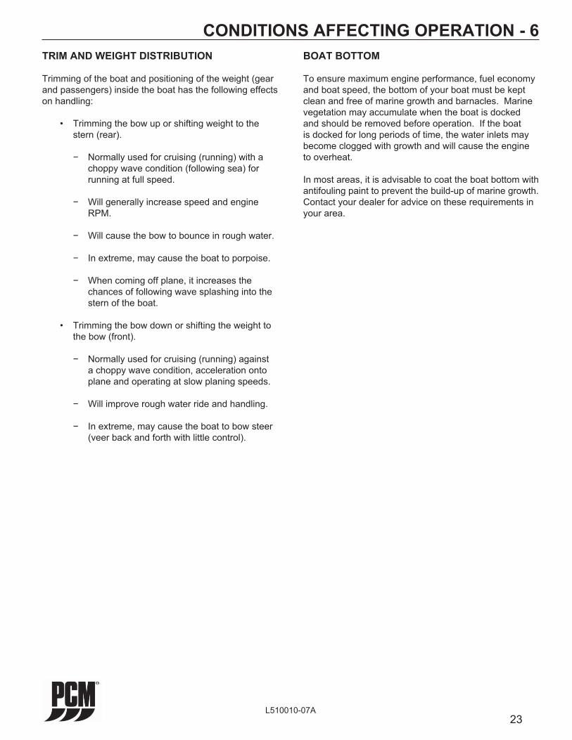
TRIM AND WEIGHT DISTRIBUTION
Trimming of the boat and positioning of the weight (gear and passengers) inside the boat has the following effects on handling:
• Trimming the bow up or shifting weight to the stern (rear).
− Normally used for cruising (running) with a choppy wave condition (following sea) for running at full speed.
− Will generally increase speed and engine RPM.
− Will cause the bow to bounce in rough water.
− In extreme, may cause the boat to porpoise.
− When coming off plane, it increases the chances of following wave splashing into the stern of the boat.
• Trimming the bow down or shifting the weight to the bow (front).
− Normally used for cruising (running) against a choppy wave condition, acceleration onto plane and operating at slow planing speeds.
− Will improve rough water ride and handling.
− In extreme, may cause the boat to bow steer (veer back and forth with little control).
CONDITIONS AFFECTING OPERATION - 6BOAT BOTTOM
To ensure maximum engine performance, fuel economy and boat speed, the bottom of your boat must be kept clean and free of marine growth and barnacles. Marine vegetation may accumulate when the boat is docked and should be removed before operation. If the boat is docked for long periods of time, the water inlets may become clogged with growth and will cause the engine to overheat.
In most areas, it is advisable to coat the boat bottom with antifouling paint to prevent the build-up of marine growth. Contact your dealer for advice on these requirements in your area.

24L510010-07A
CONDITIONS AFFECTING OPERATION - 6
CAUTION
Prolonged WOT operation will shorten the life of your engine and could cause premature engine failure. See NORMAL CRUISING SPEEDS in SPECIFICATIONS. Problems caused by WOT operation are considered abuse and are not covered under the PCM Warranty.
PROPELLER SELECTION
Best all-around performance and maximum engine life is achieved when the engine is propped to run near the top of (but within) the recommended full throttle RPM range with a normal load. See ENGINE SPECIFICATIONS for rated full throttle RPM for your model engine.
Generally, gross weight (total weight of the entire boat, including full fuel and water, optional equipment, passengers and other miscellaneous gear) is one of the major factors and should be one of the primary considerations when selecting a propeller. Other factors to take into consideration are as follows:
• Warmer weather and higher humidity will cause an RPM loss.
• Operating the boat in a higher elevation will cause an RPM loss.
• Operating the boat with an increased load will cause an RPM loss (additional equipment, passengers, etc.).
If full throttle RPM is above or below the recommended range as stated in ENGINE SPECIFICATIONS, the propeller must be changed to prevent loss of performance. A one-inch change in either the pitch or diameter of a given propeller will generally change engine RPM by 150 to 250 RPM.
ENGINE RPM CHART
Minimum Model Full Load Preferred Maximum
MP 5.0L 4600 4800 5000
MP 5.7L 4800 5000 5200
MP 6.0L 4800 5200 5300
IMPORTANT NOTICE: Your new PCM engine incorporates an RPM “MAX GOVERNOR” in order to prevent the engine from over-revving. Operation above the Maximum RPM listed, in the chart above, is not recommended. If your engine is operating above the maximum RPM listed, a higher pitched propeller would be required to lower the engine maximum RPM to the Preferred RPM listed in the chart above.

25L510010-07A
ENGINE BREAK-IN PERIOD - 7
The break-in period of your engine is the fi rst 25 hours of operation. Proper engine break-in is essential to achieve maximum performance, longevity and minimum oil consumption. During the break-in period, the following operation guidelines must be adhered to:
• After the engine is thoroughly warmed up, and the boat is underway, open the throttle to wide open throttle until maximum RPM is reached. DO NOT EXCEED MAXIMUM RPM. (RPM should cease climbing after 10 to 20 seconds).
The engine oil level should be checked often and oil added when necessary. It must be understood that every internal combustion engine will use a certain amount of oil during operation to act as a lubricating and cooling agent, especially during the break-in period. Oil consumption should decrease and become stabilized after approximately 100 hours of operation.
At the end of your 25-hour break-in period, contact your dealer and have the recommended 25-hour inspection done.
NOTICE: PCM Engines assumes no responsibility for the costs related to the 25-hour inspection. This is the owner’s responsibility.
WARNING
Use this procedure ONLY when conditions are such that it can be done in complete safety.
CAUTION
DO NOT operate at full throttle in neutral at any time, or at sustained full throttle during the fi rst 5 hours of operation. Thereafter, use sustained wide open throttle in the event of an emergency.
CAUTION
DO NOT attempt to break in any engine by prolong idling, or running at the dock.
• Reduce the throttle to 2800 - 3000 RPM, and cruise at or below this speed for 1/2 hour. Reduce the speed to idle. Go to wide open throttle until maximum RPM is reached and operate for approximately 1 minute. Reduce throttle to 2800-3000 RPM and operate for a few minutes. (Bringing the engine speed from idle to wide open throttle will load the engine and assist in seating the piston rings). This cycle should be repeated from time to time during the fi rst 5 hours of operation, but wide open throttle should not be sustained for more than 1 minute.
• During the remaining 20 hours of break in period, the engines can be run at cruise speeds that are approximately 75-80% of the wide open throttle RPM, occasionally varying the cruise speed by 100 RPM.
• During the early part of the break in period, the correct propeller selection can be confi rmed. (With a normal load aboard, the engine’s RPM should reach, but not exceed, the maximum RPM as listed in the specifi cations section).
• During the break in, all gauges should be watched carefully, and the speed should be reduced if abnormal readings become evident.
26L510010-07A
25-HOUR ENGINE INSPECTION - 8After the fi rst 25 hours of operation, it is recommended that the engine be given an inspection. Your boat dealer or a PCM servicing dealer should be contacted to perform the necessary checks and adjustments to ensure the proper engine performance. The following maintenance should be performed:
• Change the engine oil and fi lter.
• Replace the primary fuel fi lter
• Check the engine alignment.
• Inspect the accessory drive belt(s) and check the tension.
• Check all the fl uid levels.
• Check the throttle and the shift cable adjustments and check for freedom of movement.
• Cooling System - Inspect all the hoses for leaks, damage and deterioration. Check all the hose clamps for adequate tightness.
• Exhaust System - Inspect the entire exhaust system for leaks, damage and deterioration. Check all the hose clamps for adequate tightness.
• Battery - Check the electrolyte level and specifi c gravity. Inspect the case for damage. Check the battery cables and connections.
• Engine Assembly - Check for loose, missing or damaged parts. Pay close attention to engine mounts, starter and alternator mounting fasteners.
NOTICE: PCM Engines assumes no responsibility for the costs related to the 25-hour inspection. This is the owner’s responsibility.

27L510010-07A
FUEL REQUIREMENTS - 9GASOLINE REQUIREMENTS
Figure 9-1 Fuel RequirementsNOTICE: Most PCM Fuel Injected engines are calibrated to operate on 87 octane fuel and maximum performance is obtained when using this fuel. Some applications may require a higher octane fuel. These particular applications will be noted.If a slight pinging is heard during acceleration and the proper octane fuel is being used, it is considered normal. If a constant, heavy knock occurs, the engine should be evaluated by a PCM Marine Engines service technician.
GASOLINE CONTAINING ALCOHOL
The implementation of ethanol-based fuel is spreading rapidly throughout the United States. As such, PCM Engines provides the following information regarding the use of this fuel.This information addresses the use of ethanol fuels in PCM ENGINES ONLY. It does not address the use of ethanol fuels in vessel related components such as boat gas tanks, boat fuel lines, etc.Ethanol blended fuel rated E10 or less is acceptable to use. Fuels rated higher than E10 SHOULD NOT BE USED. Ethanol fuels rated higher than E10 could potentially damage the engine and/or present an unsafe boating condition. Damage to the engine resulting from the use of ethanol fuel rated higher than E10 IS NOT covered by the warranty.
UNLEADED
REGULARUNLEADED
87
$
MINIMUM OCTANE RATING
R + M/2 METHOD
87
E10E10
CAUTION
Do Not use any gasoline that contains METHANOL. This fuel is very corrosive and will create unsafe operating conditions. Serious damage will result from the continued use of fuel containing METHANOL. Any resulting engine damage will not be covered by the warranty.
If ethanol blended fuel rated E10 or less is used, or if the presence of alcohol is uncertain, more frequent inspections and service of the complete fuel system are required. Any sign of fuel leakage or deterioration must be repaired immediately before further engine operation.It is important to note that ethanol blended fuel will act as a solvent and will attract and hold moisture. Without proper fuel stabilization and fuel fi ltration, ethanol blended fuel may cause the following: • Excessive moisture (water) may cause lean
operation to include hard starting and operating diffi culties such as, vapor lock, low speed stalling, and shortened fuel shelf life.
• Acting as a solvent, ethanol blended fuel may cause gum, sediment, sludge, and other particles to be loosened and carried through the fuel system to the engine.
Fuel system or engine damage caused by contamination from water, foreign particles, sludge, or gums entering or forming in the fuel system is not covered by the PCM Limited Warranty.
Fuel Stabilizer Recommendations for Ethanol Blend FuelThe use of a commercially available fuel stabilizer, such as STA-BIL®, is recommended when storing ethanol-blended fuel for more than 2 weeks.
CAUTION
Fire and Explosion Hazard - Gasoline is extremely fl ammable and highly explosive, and , if ignited, can cause serious bodily injury or death. Careful inspection of the entire fuel system including, but not limited to, fuel tanks, fuel lines, fuel fi lters and all fi ttings is mandatory, especially after periods of storage. Replace any component that shows signs of leakage, corrosion, deterioration, swelling, hardening or softening.
WARRANTY NOTICE: Damage caused to the engine through the use of improper gasoline, low-quality or gasoline with an octane rating below the minimum requirements listed below, is considered misuse of the engine. Such damage is not covered by the PCM Marine Engines warranty.The ignition timing set by the factory requires the use of a high-quality lead-free regular gasoline with the following octane specifi cation.Pump Octane Number (R+M/2) (PUMP) - 87

28L510010-07A
OIL REQUIREMENTS - 10ENGINE OIL RECOMMENDATIONS
Use of Supplemental Additives
Engine oils meeting PCM Engines’ recommendations already contain a balanced additive treatment. The use of supplemental additives which are added to the engine oil by the customer are unnecessary and may be harmful. PCM Engines does not review, approve or recommend such products.
Synthetic Oils
Synthetic engine oils may be used in PCM Marine Engines. Synthetic oils must meet the Engine Oil Requirements for Classifi cation and Viscosity listed below. The use of synthetic oil does not permit the extension of oil change intervals.
Engine Oil Requirements
The following chart shows the recommended oil viscosity for various ambient temperature ranges:
Prevailing Ambient Recommended A.P.I. Temperature Classifi cation & Viscosity
Above 50˚F SAE 15W-40 “SM”
Below 50˚F SAE 5W-30 “SM”
IMPORTANT: The use of oils which contain “solid” additives, non-detergent oils or low quality oils specifi cally are not recommended.
WARRANTY NOTICE: PCM Engines reserves the right to refuse warranty on part(s) and/or engine(s) damaged by using improper fuels and engine oils.
Oil Change Intervals (Common)
Crankcase oil and oil fi lter change - Recommended intervals:
• Initial oil change - 1st 60 days or 25 hours of operation, whichever occurs fi rst
• Regular oil changes - Every 50 hours of operation or 120 days, whichever occurs fi rst
TRANSMISSION AND “V”-DRIVE OIL REQUIREMENTS
Recommended A.P.I. Transmission Classifi cation and and “V” Drive Viscosity
PCM Dexron III Automatic Transmissions Transmission Fluid (ATF) or equivalent
PCM V-Drive Mobiltrans SHC 50 Transmissions Synthetic Transmission Lubricant (R190250)
Walters “V”-Drive SAE 30
Dexron III Automatic All Hurth Gear Transmission Fluid (ATF) Transmissions or equivalent
29L510010-07A
ENGINE MAINTENANCE - 11ENGINE MAINTENANCERefer to the MAINTENANCE SCHEDULE for a complete listing of required maintenance and the frequency at which it should be performed. Some procedures may be performed by the owner/operator while others should be performed by an authorized PCM Engines Dealer. Before performing any maintenance or repair procedure not covered in this manual, it is strongly recommended that a PCM Engines repair manual be purchased and read thoroughly.
CHECKING FLUID LEVELSEngine Crankcase Oil
CAUTION
Do Not overfi ll engine crankcase with oil. Excessive oil can lead to premature engine component failure and/or loss of performance.
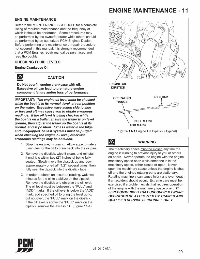
IMPORTANT: The engine oil level must be checked while the boat is in its normal, level, at rest position on the water. Excessive wave action side to side or fore and aft may cause you to obtain erroneous readings. If the oil level is being checked while the boat is on a trailer, ensure the trailer is on level ground, then adjust the trailer so the boat is at its normal, at rest position. Excess water in the bilge and, if equipped, ballast systems must be purged when checking the engine oil level, otherwise erroneous readings may be obtained. 1. Stop the engine, if running. Allow approximately
5 minutes for the oil to drain back into the oil pan. 2. Remove the dipstick, wipe it clean, and reinstall
it until it is within two (2”) inches of being fully seated. Slowly move the dipstick up and down approximately one-half (1/2”) several times; then fully seat the dipstick into the dipstick tube.
3. In order to obtain an accurate reading, wait two minutes for the oil to stabilize on the dipstick. Remove the dipstick and observe the oil level. The oil level must be between the “FULL” and “ADD” marks. If the oil level is below the “ADD” mark, add specifi ed oil to bring the level up to, but not over, the “FULL” mark on the dipstick. If the oil level is above the “FULL” mark on the dipstick, remove the excess oil. (Figure 11-1)
WARNING
The machinery space must be closed anytime the engine is running to prevent injury to you or others on board. Never operate the engine with the engine machinery space open while someone is in the machinery space, either closed or open. Never open the machinery space unless the engine is shut off and the engines rotating parts are stationary. Rotating machinery can cause injury and even death if an accident should occur. Extreme care must be exercised if a problem exists that requires operation of the engine with the machinery space open. IT IS RECOMMENDED THAT UNCOVERED ENGINE OPERATION BE ATTEMPTED BY TRAINED AND QUALIFIED SERVICE PERSONNEL ONLY.
Figure 11-1 Engine Oil Dipstick (Typical)
ENGINE OIL
DIPSTICK
OPERATING
RANGE
ADD MARK
FULL MARK
DIPSTICK
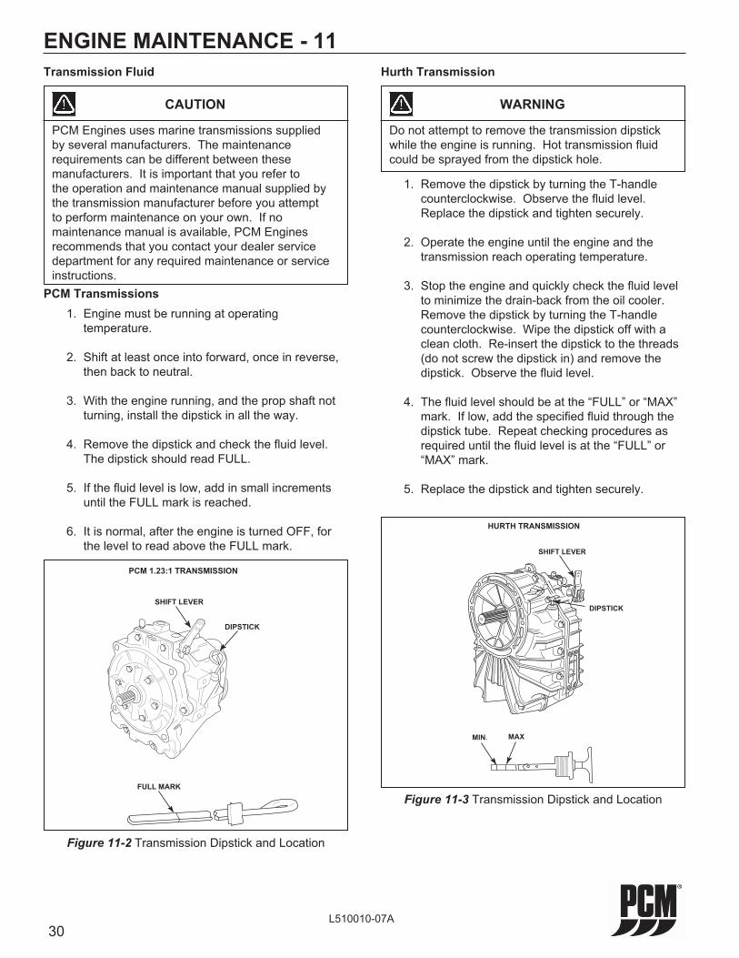
30L510010-07A
ENGINE MAINTENANCE - 11
Figure 11-2 Transmission Dipstick and Location
FULL MARK
DIPSTICK
SHIFT LEVER
PCM 1.23:1 TRANSMISSION
Figure 11-3 Transmission Dipstick and Location
MIN.
HURTH TRANSMISSION
SHIFT LEVER
DIPSTICK
MAX
Transmission Fluid
CAUTION
PCM Engines uses marine transmissions supplied by several manufacturers. The maintenance requirements can be different between these manufacturers. It is important that you refer to the operation and maintenance manual supplied by the transmission manufacturer before you attempt to perform maintenance on your own. If no maintenance manual is available, PCM Engines recommends that you contact your dealer service department for any required maintenance or service instructions.
PCM Transmissions 1. Engine must be running at operating
temperature.
2. Shift at least once into forward, once in reverse, then back to neutral.
3. With the engine running, and the prop shaft not turning, install the dipstick in all the way.
4. Remove the dipstick and check the fl uid level. The dipstick should read FULL.
5. If the fl uid level is low, add in small increments until the FULL mark is reached.
6. It is normal, after the engine is turned OFF, for the level to read above the FULL mark.
1. Remove the dipstick by turning the T-handle counterclockwise. Observe the fl uid level. Replace the dipstick and tighten securely.
2. Operate the engine until the engine and the transmission reach operating temperature.
3. Stop the engine and quickly check the fl uid level to minimize the drain-back from the oil cooler. Remove the dipstick by turning the T-handle counterclockwise. Wipe the dipstick off with a clean cloth. Re-insert the dipstick to the threads (do not screw the dipstick in) and remove the dipstick. Observe the fl uid level.
4. The fl uid level should be at the “FULL” or “MAX” mark. If low, add the specifi ed fl uid through the dipstick tube. Repeat checking procedures as required until the fl uid level is at the “FULL” or “MAX” mark.
5. Replace the dipstick and tighten securely.
WARNING
Do not attempt to remove the transmission dipstick while the engine is running. Hot transmission fl uid could be sprayed from the dipstick hole.
Hurth Transmission

31L510010-07A
ENGINE MAINTENANCE - 11LUBRICATION
Throttle Cable
Lubricate pivot points and exposed cable (Figure 11-5) with SAE 30W-30 engine oil.
Figure 11-5 Typical Throttle Cable
Shift Cable
Lubricate pivot points and exposed cable (Figure 11-6) with SAE 30W-30 engine oil.
Figure 11-6 Typical Shift Cable
CABLE
CLIP
BALL JOINT
LUBRICATION
POINTS
LUBRICATION
POINTS
Figure 11-4 Transmission Service Location
PLEASURECRAFTENGINE GROUP
POWER PLUSRATIO 1.48
MADE IN USA
Oil Fill/Drain Plug Oil Fill/Drain
Plug
Raw WaterDrain Plug
All PCM Power-Plus “V” Drive transmissions are designed to be ‘Maintenance Free’. Inspect fl uid level after the fi rst 25 hours of use and annually thereafter. Fluid should only be changed if evidence of contamination is present. Use Mobiltrans SHC 50 synthetic transmission lubricant. PCM P/N: R190250. 1. Remove the drain/fi ll plug from the transmission.
Observe the fl uid level.
2. The fl uid level should be at the bottom of the threaded hole. If low, add the specifi ed fl uid through the threaded hole to the proper level.
NOTE: The transmission fl uid is a very high viscosity, to make adding fl uid easier, remove both fi ll plugs.
3. Replace the drain/fi ll plug(s) and tighten securely.
WARNING
Do not attempt to remove the transmission drain/fi ll plug while the engine is running or while the transmission is hot. Hot transmission fl uid could be sprayed from the hole.
PCM Power-Plus V-Drive Transmission

32L510010-07A
ENGINE MAINTENANCE - 11ELECTRICAL SYSTEM RELAY AND FUSE BLOCKMAIN PANEL FUSEPCM engines are equipped with a 40 Amp PANEL fuse which provides electrical overload protection for the boat’s instrumentation wiring and components. Should an electrical overload occur, the PANEL fuse will open and prevent electrical current fl ow.When this fuse opens, the cause for the high current draw must be found and corrected. Check the battery and alternator connections and all other harness connectors between the boat and the engine main harness. Check for loose or disconnected lead wires and shorted circuits. Replace the PANEL fuse and resume operation. If the cause of the overload cannot be found, consult an authorized PCM Engines dealer to make necessary repairs.ELECTRICAL SYSTEM FUSESPCM engines utilize fuses to protect critical engine components and devices. The fuel pump, ECM, ignition components, fuel injectors, starter and diagnostic devices are protected by fuses. The fuse block is mounted on a bracket near the rear of the engine.
BOAT’S IGNITION FUSEIf the engine will not crank when the ignition key is turned to the START position, fi rst check that the shift lever is in the neutral position and the safety lanyard (if equipped) is attached properly. If none of the Fuse Block fuses are open, check for a blown boat ignition fuse. The boat’s ignition fuse may be located on the instrument panel, the fuse holder block or as part of the helm’s instrument wiring harness. Check the wiring diagrams supplied from the boat manufacturer for the exact location.
Figure 11-7 Electrical System Relay and Fuse Block
ELECTRICAL SYSTEM WIRING AND CONNECTORSThe electrical system wiring and connectors should be checked periodically for loose or dirty connections and damaged wiring. If electrical components or wiring show signs of corrosion, deterioration or damage, consult an authorized PCM Engines dealer to make necessary repairs.
40
20
15
20
20
5
15
33L510010-07A
ENGINE MAINTENANCE - 11BATTERY
WARNING
Battery electrolyte is a corrosive acid and should be handled with care. If electrolyte is spilled or splashed on any part of the body, IMMEDIATELY fl ush the exposed area with liberal amounts of water and obtain medical aid as soon as possible. Safety glasses and rubber gloves are recommended when handling batteries or fi lling with electrolyte.
WARNING
Hydrogen gases that escape from the battery when charging are highly explosive. Do not use jumper cables and a booster battery to start the engine. Do not recharge a weak battery in the boat. Remove the battery from the boat and recharge in a well ventilated area away from fuel vapors, sparks and open fl ames.
Follow maintenance instructions and warnings as supplied by the battery manufacturer. If this information is not available, follow these guidelines for the proper battery care.
• Do not operate the engine with an open in the battery circuit, as this may cause damage to the alternator. Make sure that all connections are clean and secure.
• When removing the battery cables, always remove the negative (-) cable fi rst, and then remove the positive (+) cable. When installing battery cables, install the positive (+) cable fi rst, then install the negative (-) cable.
• Periodically check the battery for signs of corrosion, frayed battery leads or cracked case. Repair or replace as necessary.
• Periodically check the electrolyte level. Add distilled water to bring up to the proper levels.
IMPORTANT: Your engine is designed to work with the standard electronics installed in your boat. If you add other electrical components or accessories, you could change the way the fuel injection controls your engine or the overall electrical system functions. Before adding electrical equipment, consult your dealer. If you don’t, your engine may not perform properly.
CAUTION
Add-on equipment may adversely affect the alternator output or overload the electrical system. Any damage caused as a result will not be covered by, and may void, your warranty.

34L510010-07A
ENGINE MAINTENANCE - 11FRESH-WATER COOLING SYSTEM SACRIFICIAL ZINC ANODE
Located in the raw water side of the heat exchanger is a zinc anode which is marked by a decal. To check, remove the plug and visually check the condition of the zinc rod. The length of the zinc rod when new is approximately 1.5 inches. If more than one half of the zinc is gone, replace with a new zinc anode.
Different geographic locations and water make-up can result in either high or low sacrifi cial requirements. A high rate of zinc anode consumption should also alert the owner to a possibility of an improperly wired boat accessory, which would require complete checking by qualifi ed service personnel.
Figure 11-8 Zinc Anode Location F.W.C. Heat Exchanger (6.0L)
P/N 23627
Remove and check condition of zinc pencilevery 30 days. Replace if more than 50%missing with Crusader Part #10972.
HEAT EXCHANGERPROTECTIVE ANODE ZINC
ANODE

35L510010-07A
ENGINE MAINTENANCE - 11CHECKING COOLANT LEVEL
WARNING
Do not remove cooling system fi ller cap when the engine is hot. Allow the engine to cool and then remove the pressure cap slowly, allowing the pressure to vent. Hot coolant, under pressure, may discharge violently and cause severe burns.
Degas Bottle
The “see-through” degas bottle is connected to the heat exchanger by a small hose. The degas bottle collects coolant that expands with rising temperature, and would otherwise overfl ow from the system. Coolant level should be at or slightly above the “ADD” mark on the bottle when the system is cold. Coolant should be added ONLY to the bottle when the system cools. Add specifi ed coolant as required.
Figure 11-9 Checking Coolant Level (6.0L)
DEGASBOTTLE
PRESSURE CAP

36L510010-07A
ENGINE MAINTENANCE - 11FLUSHING COOLING SYSTEM - SEA-WATER SECTION
To prevent silt and/or salt build-up in the cooling system (fresh or raw-water cooled), fl ush the sea-water section of the cooling system with fresh water at specifi ed intervals. Close seacock (if applicable) before removing inlet hose.
CAUTION
Do not operate the engine without suffi cient amount of water being supplied to the sea-water pump. The sea-water pump impeller may be damaged and subsequent overheating damage may result.
Figure 11-10 Typical Sea-Water Inlet
CAUTION
Do not run the engine above 1500 RPM when fl ushing. Suction created by the sea-water pump may collapse the fl ushing hose, causing the engine to overheat. Watch the temperature gauge while fl ushing to ensure the engine does not overheat.
ATTACH
FLUSHING
ADAPTER
HERE
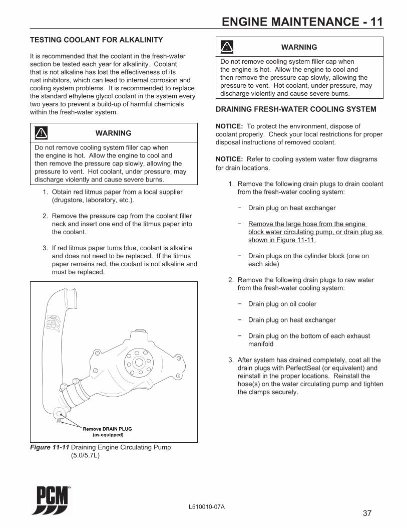
37L510010-07A
ENGINE MAINTENANCE - 11TESTING COOLANT FOR ALKALINITY
It is recommended that the coolant in the fresh-water section be tested each year for alkalinity. Coolant that is not alkaline has lost the effectiveness of its rust inhibitors, which can lead to internal corrosion and cooling system problems. It is recommended to replace the standard ethylene glycol coolant in the system every two years to prevent a build-up of harmful chemicals within the fresh-water system. DRAINING FRESH-WATER COOLING SYSTEM
NOTICE: To protect the environment, dispose of coolant properly. Check your local restrictions for proper disposal instructions of removed coolant.
NOTICE: Refer to cooling system water fl ow diagrams for drain locations.
1. Remove the following drain plugs to drain coolant from the fresh-water cooling system:
− Drain plug on heat exchanger
− Remove the large hose from the engine block water circulating pump, or drain plug as shown in Figure 11-11.
− Drain plugs on the cylinder block (one on each side)
2. Remove the following drain plugs to raw water from the fresh-water cooling system:
− Drain plug on oil cooler
− Drain plug on heat exchanger
− Drain plug on the bottom of each exhaust manifold
3. After system has drained completely, coat all the drain plugs with PerfectSeal (or equivalent) and reinstall in the proper locations. Reinstall the hose(s) on the water circulating pump and tighten the clamps securely.
WARNING
Do not remove cooling system fi ller cap when the engine is hot. Allow the engine to cool and then remove the pressure cap slowly, allowing the pressure to vent. Hot coolant, under pressure, may discharge violently and cause severe burns.
1. Obtain red litmus paper from a local supplier (drugstore, laboratory, etc.).
2. Remove the pressure cap from the coolant fi ller neck and insert one end of the litmus paper into the coolant.
3. If red litmus paper turns blue, coolant is alkaline and does not need to be replaced. If the litmus paper remains red, the coolant is not alkaline and must be replaced.
WARNING
Do not remove cooling system fi ller cap when the engine is hot. Allow the engine to cool and then remove the pressure cap slowly, allowing the pressure to vent. Hot coolant, under pressure, may discharge violently and cause severe burns.
Figure 11-11 Draining Engine Circulating Pump (5.0/5.7L)
Remove DRAIN PLUG (as equipped)
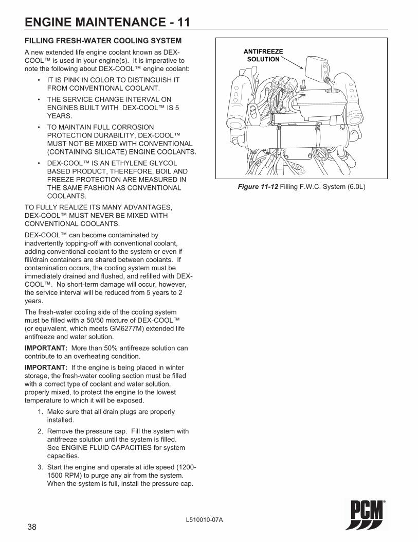
38L510010-07A
ENGINE MAINTENANCE - 11FILLING FRESH-WATER COOLING SYSTEMA new extended life engine coolant known as DEX-COOL™ is used in your engine(s). It is imperative to note the following about DEX-COOL™ engine coolant: • IT IS PINK IN COLOR TO DISTINGUISH IT
FROM CONVENTIONAL COOLANT. • THE SERVICE CHANGE INTERVAL ON
ENGINES BUILT WITH DEX-COOL™ IS 5 YEARS.
• TO MAINTAIN FULL CORROSION PROTECTION DURABILITY, DEX-COOL™ MUST NOT BE MIXED WITH CONVENTIONAL (CONTAINING SILICATE) ENGINE COOLANTS.
• DEX-COOL™ IS AN ETHYLENE GLYCOL BASED PRODUCT, THEREFORE, BOIL AND FREEZE PROTECTION ARE MEASURED IN THE SAME FASHION AS CONVENTIONAL COOLANTS.
TO FULLY REALIZE ITS MANY ADVANTAGES, DEX-COOL™ MUST NEVER BE MIXED WITH CONVENTIONAL COOLANTS.DEX-COOL™ can become contaminated by inadvertently topping-off with conventional coolant, adding conventional coolant to the system or even if fi ll/drain containers are shared between coolants. If contamination occurs, the cooling system must be immediately drained and fl ushed, and refi lled with DEX-COOL™. No short-term damage will occur, however, the service interval will be reduced from 5 years to 2 years.The fresh-water cooling side of the cooling system must be fi lled with a 50/50 mixture of DEX-COOL™ (or equivalent, which meets GM6277M) extended life antifreeze and water solution. IMPORTANT: More than 50% antifreeze solution can contribute to an overheating condition.IMPORTANT: If the engine is being placed in winter storage, the fresh-water cooling section must be fi lled with a correct type of coolant and water solution, properly mixed, to protect the engine to the lowest temperature to which it will be exposed. 1. Make sure that all drain plugs are properly
installed. 2. Remove the pressure cap. Fill the system with
antifreeze solution until the system is fi lled. See ENGINE FLUID CAPACITIES for system capacities.
3. Start the engine and operate at idle speed (1200-1500 RPM) to purge any air from the system. When the system is full, install the pressure cap.
Figure 11-12 Filling F.W.C. System (6.0L)
ANTIFREEZE
SOLUTION

39L510010-07A
ENGINE MAINTENANCE - 11CLEANING SEA-WATER SECTION OF HEAT EXCHANGER - FRESH-WATER COOLED MODELS ONLY
The sea-water section of the heat exchanger should be cleaned whenever there is a noticeable decrease in cooling effi ciency. You may use the following procedure for cleaning, or, if the build-up of scale and mineral deposits is heavy, it is recommended that the heat exchanger be removed and taken to a repair facility to be boiled out (such as a radiator repair facility).
1. Remove the bolts securing the heat exchanger end plates. Remove the end plates and gaskets.
2. Clean the water passages in the heat exchanger by inserting a suitable-size wire brush into each passage. Use compressed air to blow out loose particles.
3. Clean the gasket surfaces on the end plates and the heat exchanger. Apply PerfectSeal to both sides of the new gaskets. Install the end plates and the new gaskets onto the heat exchanger. Install the bolts and tighten securely.
4. Start the engine and inspect for leaks.
Figure 11-13 Heat Exchanger and End Plate Removal(Typical)
HEAT
EXCHANGER
COOLANT
DRAIN PLUG
RAW WATER
DRAIN PLUGGASKET
PLATE
BOLT
40L510010-07A
WARNING
Extreme caution must be exercised when servicing the fuel system and/or replacing fuel fi lter. Gasoline is extremely fl ammable and highly explosive under certain conditions. Be sure the ignition key is off and do not smoke or allow open fl ame in the area while servicing. Wipe up any spilled fuel immediately.
WARNING
Extreme caution must be exercised when servicing the fuel system. The fuel system operates under high pressure. Use caution when removing or replacing components, as residual pressure may be present.
WARNING
Make sure that there are no fuel leaks before closing the engine hatch.
ENGINE MAINTENANCE - 11FUEL SYSTEM DESCRIPTION
WARNING
Visually inspect unit for fuel leaks before operating the engine. If fuel leaks are present, DO NOT operate the engine, contact your service center immediately.
Fuel Control Cell (FCC) Fuel SystemThe Fuel Control Cell (FCC) eliminates vapor lock and air ingestion caused by fuel tank slosh, and provides the necessary fi ltration and water separation.The FCC system incorporates two (2) fuel pumps to provide an uninterrupted fl ow of fuel to your PCM marine engine. Fuel is fed into the FCC bowl by a low-pressure, high-volume electric fuel pump. This pump fl ows fuel at a volume much greater than the fuel fl ow rate required of the high-pressure pump and engine demands. The high-pressure pump, mounted inside the FCC bowl, provides the necessary fuel pressure and volume to maintain proper engine performance. The FCC constantly has an ample supply of fuel to meet the idle, cruise and acceleration fuel requirements of the engine.The fuel pressure regulator may be located on the fuel rail or inside the FCC bowl, controls the fuel pressure and maintains a constant pressure across the fuel delivery system. Excess fuel, not used by the engine, returns to the FCC bowl.The fuel delivered to the engine by the FCC is fi ltered by a fi lter and water separator element, which surrounds the high pressure pump inside the FCC bowl.As indicated above, fuel enters the FCC bowl from two (2) locations, the low-pressure pump (initial input) and the fuel pressure regulator (unused, recirculating fuel). Fuel exits the FCC bowl at two (2) locations, the high-pressure output to the fuel injection system and all excess fuel in the FCC bowl is routed back to the tank via the return line.
WARNING
Accumulation of water and other fuel contaminants may form corrosive compounds that can damage the fuel fi lter, and result in fuel leakage. Ethanol blended fuel may increase this risk. For this reason, annual replacement of the fuel fi lter, at a minimum, is required to avoid risk of explosion or fi re.

41L510010-07A
ENGINE MAINTENANCE - 11
Figure 11-14 Fuel Control Cell (FCC) Fuel System (Typical)
PN: R080024
INOUT
FROMFUELTANK
PRIMARYFUEL
FILTER
FUELSUPPLY
LINE
FUELRETURN
LINE
FUELCONTROL
CELL
LOW-PRESSUREFUEL PUMP
5.0/5.7L ONLY
RETURNTO
FUELTANK
Servicing the FCCThe frequency of draining the water or replacing the fi lter element is determined by the contamination level of the fuel. Replace the fi lter element at least once a year, or when a loss of power is noticed (whichever occurs fi rst).
WARNING
Improper use, installation or servicing may cause an explosion or fi re resulting in bodily injury, or death. This unit should only be serviced by a qualifi ed technician. Read and follow all instructions before proceeding. Run the engine and check for fuel leaks after installation, element replacement or draining the bowl. DO NOT remove the FCC bowl unless servicing the fi lter element, otherwise contamination or bowl O-ring swelling may result.
Draining the FCC Bowl, ENGINE OFF 1. Disconnect the two-wire electrical connectors
from the FCC and the Low Pressure Fuel Pump (LPFP).
2. Remove the 7/16” plug, and drain the bowl contents into an approved container.
CAUTION: Both fuel and water will drain from the FCC bowl. 3. Apply pipe sealant, suitable for use with gasoline,
to the threads of the 7/16” plug.
Primary Fuel Filter (FCC Clamp-on Canister)
WARNING
Extreme caution must be exercised when servicing the fuel system. The fuel system operates under high pressure. Use caution when removing or replacing components, as residual pressure may be present.
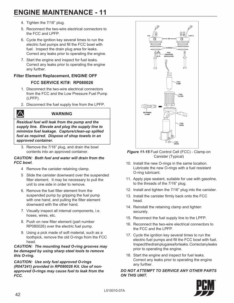
42L510010-07A
ENGINE MAINTENANCE - 11 4. Tighten the 7/16” plug. 5. Reconnect the two-wire electrical connectors to
the FCC and LPFP. 6. Cycle the ignition key several times to run the
electric fuel pumps and fi ll the FCC bowl with fuel. Inspect the drain plug area for leaks. Correct any leaks prior to operating the engine.
7. Start the engine and inspect for fuel leaks. Correct any leaks prior to operating the engine any further.
Filter Element Replacement, ENGINE OFFFCC SERVICE KIT#: RP080026
1. Disconnect the two-wire electrical connectors from the FCC and the Low Pressure Fuel Pump (LPFP).
2. Disconnect the fuel supply line from the LPFP.
3. Remove the 7/16” plug, and drain the bowl contents into an approved container.
CAUTION: Both fuel and water will drain from the FCC bowl. 4 Remove the canister retaining clamp. 5 Slide the canister downward over the suspended
fi lter element. It may be necessary to pull the unit to one side in order to remove.
6. Remove the fuel fi lter element from the suspended pump by gripping the fuel pump with one hand, and pulling the fi lter element downward with the other hand.
7. Visually inspect all internal components, i.e. hoses, wires, etc.
8. Push on new fi lter element (part number RP080026) over the electric fuel pump.
9. Using a pick made of soft material, such as a toothpick, remove the old O-rings from the FCC head.
CAUTION: The mounting head O-ring grooves may be damaged by using sharp steel tools to remove this O-ring.CAUTION: Use only fuel approved O-rings (R047241) provided in RP080026 Kit. Use of non-approved O-rings may cause fuel to leak from the FCC.
Figure 11-15 Fuel Control Cell (FCC) - Clamp-on Canister (Typical)
FUELDRAIN
FUELBOWL
RETAININGCLAMP
FUELFILTER
FUELPUMP
FUELPRESSURE
REGULATOR
6.0L 5.0/5.7L
OR
O-RINGS
10. Install the new O-rings in the same location. Lubricate the new O-rings with a fuel resistant O-ring lubricant.
11. Apply pipe sealant, suitable for use with gasoline, to the threads of the 7/16” plug.
12. Install and tighten the 7/16” plug into the canister. 13. Install the canister fi rmly back onto the FCC
head. 14. Reinstall the retaining clamp and tighten
securely. 15. Reconnect the fuel supply line to the LPFP. 16. Reconnect the two-wire electrical connectors to
the FCC and the LPFP. 17. Cycle the ignition key several times to run the
electric fuel pumps and fi ll the FCC bowl with fuel. Inspect the drain plug area for leaks. Correct any leaks prior to operating the engine.
18. Start the engine and inspect for fuel leaks. Correct any leaks prior to operating the engine any further.
DO NOT ATTEMPT TO SERVICE ANY OTHER PARTS ON THIS UNIT.
WARNING
Residual fuel will leak from the pump and the supply line. Elevate and plug the supply line to minimize fuel leakage. Capture/clean-up spilled fuel as required. Dispose of shop towels in an approved container.
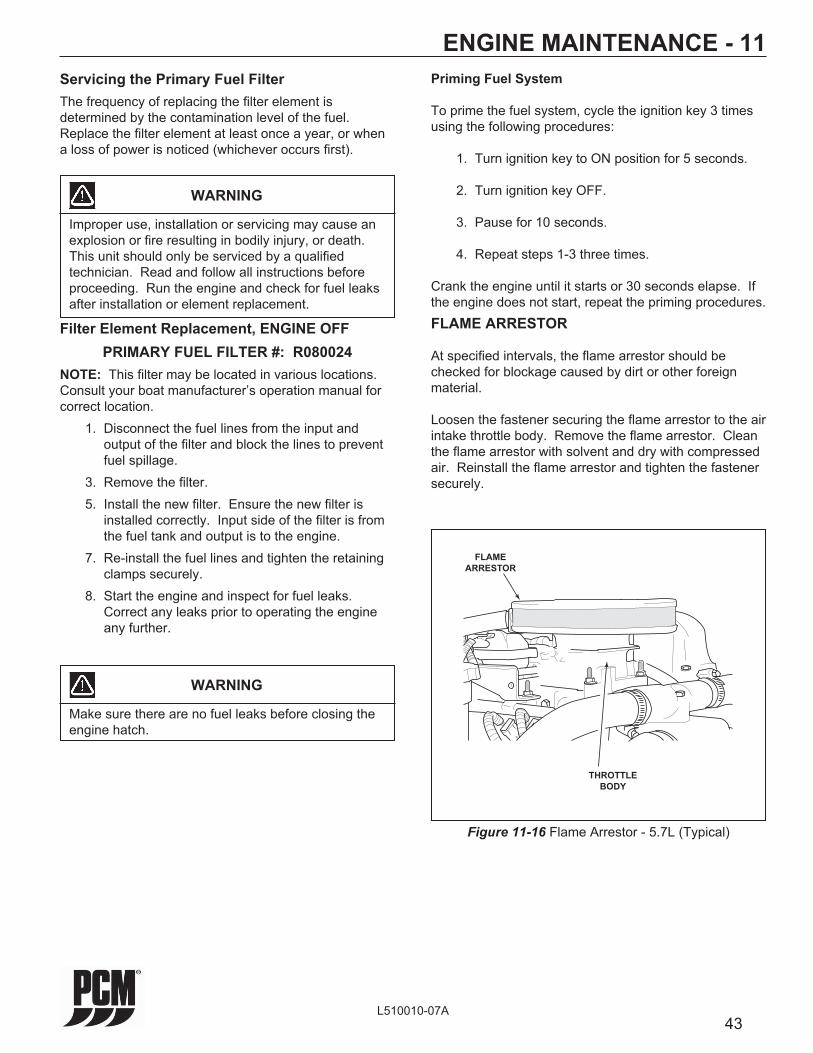
43L510010-07A
ENGINE MAINTENANCE - 11
WARNING
Make sure there are no fuel leaks before closing the engine hatch.
Priming Fuel System
To prime the fuel system, cycle the ignition key 3 times using the following procedures:
1. Turn ignition key to ON position for 5 seconds.
2. Turn ignition key OFF.
3. Pause for 10 seconds.
4. Repeat steps 1-3 three times.
Crank the engine until it starts or 30 seconds elapse. If the engine does not start, repeat the priming procedures.FLAME ARRESTOR
At specifi ed intervals, the fl ame arrestor should be checked for blockage caused by dirt or other foreign material.
Loosen the fastener securing the fl ame arrestor to the air intake throttle body. Remove the fl ame arrestor. Clean the fl ame arrestor with solvent and dry with compressed air. Reinstall the fl ame arrestor and tighten the fastener securely.
Figure 11-16 Flame Arrestor - 5.7L (Typical)
THROTTLEBODY
FLAMEARRESTOR
Servicing the Primary Fuel FilterThe frequency of replacing the fi lter element is determined by the contamination level of the fuel. Replace the fi lter element at least once a year, or when a loss of power is noticed (whichever occurs fi rst).
WARNING
Improper use, installation or servicing may cause an explosion or fi re resulting in bodily injury, or death. This unit should only be serviced by a qualifi ed technician. Read and follow all instructions before proceeding. Run the engine and check for fuel leaks after installation or element replacement.
Filter Element Replacement, ENGINE OFFPRIMARY FUEL FILTER #: R080024
NOTE: This fi lter may be located in various locations. Consult your boat manufacturer’s operation manual for correct location. 1. Disconnect the fuel lines from the input and
output of the fi lter and block the lines to prevent fuel spillage.
3. Remove the fi lter. 5. Install the new fi lter. Ensure the new fi lter is
installed correctly. Input side of the fi lter is from the fuel tank and output is to the engine.
7. Re-install the fuel lines and tighten the retaining clamps securely.
8. Start the engine and inspect for fuel leaks. Correct any leaks prior to operating the engine any further.

44L510010-07A
ENGINE MAINTENANCE - 11
Figure 11-18 Belt Tensioner (6.0L)
Figure 11-17 6.0L Accessory Drive Belt Confi guration
Belt
Tensioner
Circulation
Pump Raw Water
Pump
Crankshaft
Pulley
Alternator
Idler
A
DRIVE BELT REPLACEMENT (6.0L)6.0L SERPENTINE BELT #: R066027
1. Note the routing of the belt before removing. 2. Using a 15 mm box wrench or socket, turn the
belt tensioner to relieve the tension on the belt. Slide the belt off of the pulleys. Release the tensioner slowly to prevent the tensioner from snapping against its stop, and possibly causing damage to the tensioner.
3. Slide the new belt onto the pulleys using the same routing as noted prior to removal.
4. Compress the belt tensioner, and slide the belt over the tensioner pulley. Release the tension slowly to tension the belt.
SERVICING RAW WATER PUMP IMPELLER (6.0L)
6.0L IMPELLER KIT #: RP061022The raw water pump impeller should be serviced every 50 hours, or once a year, whichever occurs fi rst. See Maintenance Schedule.Locations “A” (Figure 11-20) are access holes in order to loosen the raw water pump attaching bolts. The bolts are secured in the pump by O-rings, and will not fall out during removal.Torque the raw water pump housing attaching bolts to 8.5-9 ft.lbs. (11.5-12 N-M), when re-installing the impeller.
DRIVE BELT INSPECTIONInspect the drive belt for excessive wear, shredding or missing sections.Inspect the drive belt for contamination from excessive dirt, oil, coolant or other substances that may effect the drive belt operation.If a problem is found, replace the belt after inspecting the following items: • All pulleys and tensioners for signs of
misalignment • All pulleys and tensioners for signs of rust or
other damage • Bent pulleys or tight bearings in the engine water
circulation pump, sea-water pump and alternator
WARNING
Engine must be shut OFF and the ignition key removed before inspecting the drive belt(s). The drive belt(s) should be checked periodically for condition and tension. If the belt(s) shows signs of cracking, glazing or deterioration, replace with new belt(s).
6.0L ACCESSORY DRIVE BELTThe PCM 6.0L engine uses a single serpentine belt to drive the engine water circulation pump, sea-water pump and the alternator.

45L510010-07A
WARNING
Engine must be shut OFF and the ignition key removed before inspecting the drive belt(s). The drive belt(s) should be checked periodically for condition and tension. If the belt(s) shows signs of cracking, glazing or deterioration, replace with new belt(s).
ENGINE MAINTENANCE - 11
Figure 11-20 Belt Tensioner (5.0/5.7L)
5.0/5.7L ACCESSORY DRIVE BELTThe PCM 5.0/5.7L engines use a single serpentine belt to drive the engine water circulation pump, sea-water pump and the alternator.
Figure 11-19 5.0/5.7L Accessory Drive Belt Confi guration
DRIVE BELT REPLACEMENT (5.0/5.7L)5.0/5.7L SERPENTINE BELT #: R066028
1. Note the routing of the belt before removing. 2. Using a 15 mm box wrench or socket, turn the
belt tensioner to relieve the tension on the belt. Slide the belt off of the pulleys. Release the tensioner slowly to prevent the tensioner from snapping against its stop, and possibly causing damage to the tensioner.
3. Slide the new belt onto the pulleys using the same routing as noted prior to removal. 4. Compress the belt tensioner, and slide the belt
over the tensioner pulley. Release the tension slowly to tension the belt.
SERVICING RAW WATER PUMP IMPELLER (5.0/5.7L)
5.0/5.7L IMPELLER KIT #: RP061022The raw water pump impeller should be serviced every 50 hours, or once a year, whichever occurs fi rst. See Maintenance Schedule.Locations “A” (Figure 11-22) are access holes in order to loosen the raw water pump attaching bolts. The bolts are secured in the pump by O-rings, and will not fall out during removal.Torque the raw water pump housing attaching bolts to 8.5-9 ft.lbs. (11.5-12 N-M), when re-installing the impeller.
Belt
Tensioner
Circulation
PumpRaw Water
Pump
Crankshaft
Pulley
Alternator
A
DRIVE BELT INSPECTIONInspect the drive belt for excessive wear, shredding or missing sections.Inspect the drive belt for contamination from excessive dirt, oil, coolant or other substances that may effect the drive belt operation.If a problem is found, replace the belt after inspecting the following items: • All pulleys and tensioners for signs of
misalignment • All pulleys and tensioners for signs of rust or
other damage • Bent pulleys or tight bearings in the engine water
circulation pump, sea-water pump and alternator

46L510010-07A
ENGINE MAINTENANCE - 11CHANGING OILS
WARNING
IMPORTANT: The Federal Water Pollution Control Act prohibits the discharge of oil or oily waste into or upon the navigable waters and continuous zone of the United States, if such discharge causes a fi lm or sheen upon, or discoloration of the surface of the water, or causes sludge or emulsion beneath the surface of the water. Violators are subject to a penalty of $5,000.00.
Refer to the MAINTENANCE SCHEDULE for oil change intervals. The engine and transmission oils should be changed prior to placing the boat into storage.The transmission oil change should be performed by an authorized PCM dealer, at specifi ed intervals. Transmission fl uids should be removed through a copper tube, that extends to the bottom of the transmission case, using a suction/vacuum type fl uid extractor.IMPORTANT: Change the engine oil when the engine is warm from operation. Warm oil fl ows more freely, and allows more foreign material and impurities to be removed.The engine oil fi lter is remote mounted. The engine block location, where the fi lter is normally mounted, is covered with an oil fi lter bypass adapter. DO NOT remove this adapter when changing the oil.
1. With the engine at normal operating temperature, locate the oil pan quick drain hose and thread the hose through the boat’s drain plug hole. (Figure 11-21). Remove the cap from the end of the quick-drain hose and insert the discharge hose into a suitable container. Allow the oil from the engine to drain until the crankcase is empty. Reinstall the cap onto the quick-drain hose and pull the hose back through the drain and secure the hose at the engine.
2. Remove the oil fi lter by turning it counterclockwise, using an oil fi lter wrench if necessary. Discard the old fi lter and sealing ring.
3. Coat the sealing ring, on the new fi lter, with a light coating of clean engine oil. Install the oil fi lter securely by hand. DO NOT overtighten.
4. Fill the engine with the recommended oil and quantity, through the oil fi ll location on the valve
Figure 11-21 Engine Oil Removal
Figure 11-22 Engine Oil Fill (5.7L)
CONTAINER
OIL QUICK-DRAIN HOSE
OILFILL
CAUTION
DO NOT OVERFILL ENGINE CRANKCASE WITH OIL. Excessive oil can lead to premature engine component failure and/or loss of performance.
cover (Figure 11-22). See OIL REQUIREMENTS page 28 and ENGINE FLUID CAPACITIES page 54, respectively.
5. Start the engine and operate for 5 minutes to circulate the oil throughout the engine. Check entire system for leaks, especially around the oil fi lter.
6. Stop the engine and wait 5 minutes to allow the oil to completely drain down. Check the oil level. Add or remove oil, as needed, to bring the engine oil to the proper level. See CHECKING FLUID LEVELS page 29 for Important Notes and Cautions to observe when checking the engine crankcase oil level.
IF YOU ARE UNSURE OF THE CORRECT AMOUNT OF OIL TO USE DURING A SERVICE INTERVAL, PERFORM THE FOLLOWING PROCEDURE: (1) Drain the oil and change the oil fi lter.
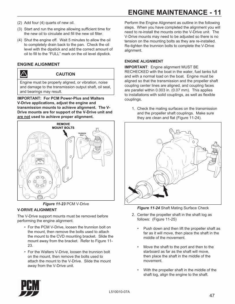
47L510010-07A
ENGINE ALIGNMENT
CAUTION
Engine must be properly aligned, or vibration, noise and damage to the transmission output shaft, oil seal, and bearings may result.
IMPORTANT: Engine alignment MUST BE RECHECKED with the boat in the water, fuel tanks full and with a normal load on the boat. Engine must be aligned so that the transmission and the propeller shaft coupling center lines are aligned, and coupling faces are parallel within 0.003 in. (0.07 mm). This applies to installations with solid couplings, as well as fl exible couplings.
1. Check the mating surfaces on the transmission and the propeller shaft couplings. Make sure they are clean and fl at (Figure 11-24).
Figure 11-24 Shaft Mating Surface Check
2. Center the propeller shaft in the shaft log as follows: (Figure 11-25)
• Push down and then lift the propeller shaft as far as it will move, then place the shaft in the middle of the movement.
• Move the shaft to the port and then to the starboard as far as the shaft will move, then place the shaft in the middle of the movement.
• With the propeller shaft in the middle of the shaft log, align the engine to the shaft.
ENGINE MAINTENANCE - 11
IMPORTANT: For PCM Power-Plus and Walters V-Drive applications, adjust the engine and transmission mounts to achieve alignment. The V-Drive mounts are for support of the V-Drive unit and are not used to achieve proper alignment.
PLEASURECRAFTENGINE GROUP
POWER PLUSRATIO 1.48
MADE IN USA
TRUNNIONBOLT
REMOVEMOUNT BOLTS
V-DRIVE ALIGNMENTThe V-Drive support mounts must be removed before performing the engine alignment. • For the PCM V-Drive, loosen the trunnion bolt on
the mount, then remove the bolts used to attach the mount to the CVD mounting bracket. Slide the mount away from the bracket. Refer to Figure 11-23.
• For the Walters V-Drive, loosen the trunnion bolt on the mount, then remove the bolts used to attach the mount to the V-Drive. Slide the mount away from the V-Drive unit.
Figure 11-23 PCM V-Drive
ENGINE ALIGNMENT
(2) Add four (4) quarts of new oil.(3) Start and run the engine allowing suffi cient time for
the new oil to circulate and fi ll the new oil fi lter.(4) Shut the engine off. Wait 5 minutes to allow the oil
to completely drain back to the pan. Check the oil level with the dipstick and add the correct amount of oil to fi ll to the “FULL” mark on the oil level dipstick.
Perform the Engine Alignment as outline in the following steps. When you have completed the alignment you will need to re-install the mounts onto the V-Drive unit. The V-Drive mounts may need to be adjusted so there is no tension on the mounting bolts as they are re-installed. Re-tighten the trunnion bolts to complete the V-Drive alignment.
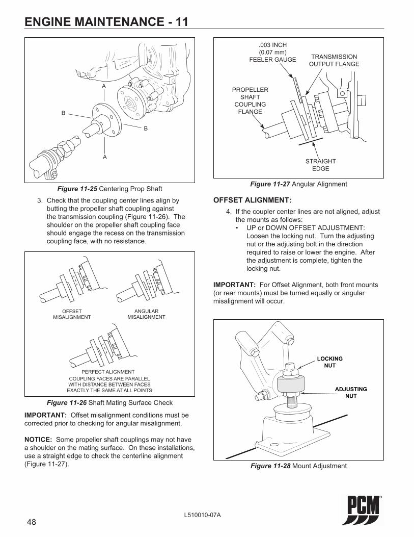
48L510010-07A
ENGINE MAINTENANCE - 11
3. Check that the coupling center lines align by butting the propeller shaft coupling against the transmission coupling (Figure 11-26). The shoulder on the propeller shaft coupling face should engage the recess on the transmission coupling face, with no resistance.
Figure 11-25 Centering Prop Shaft
B
B
A
A
IMPORTANT: Offset misalignment conditions must be corrected prior to checking for angular misalignment.
NOTICE: Some propeller shaft couplings may not have a shoulder on the mating surface. On these installations, use a straight edge to check the centerline alignment (Figure 11-27).
Figure 11-26 Shaft Mating Surface Check
OFFSETMISALIGNMENT
ANGULARMISALIGNMENT
PERFECT ALIGNMENT
COUPLING FACES ARE PARALLELWITH DISTANCE BETWEEN FACESEXACTLY THE SAME AT ALL POINTS
Figure 11-27 Angular Alignment
STRAIGHT
EDGE
TRANSMISSION
OUTPUT FLANGE
.003 INCH
(0.07 mm)
FEELER GAUGE
PROPELLER
SHAFT
COUPLING
FLANGE
OFFSET ALIGNMENT: 4. If the coupler center lines are not aligned, adjust
the mounts as follows: • UP or DOWN OFFSET ADJUSTMENT:
Loosen the locking nut. Turn the adjusting nut or the adjusting bolt in the direction required to raise or lower the engine. After the adjustment is complete, tighten the locking nut.
IMPORTANT: For Offset Alignment, both front mounts (or rear mounts) must be turned equally or angular misalignment will occur.
Figure 11-28 Mount Adjustment
LOCKING
NUT
ADJUSTING
NUT
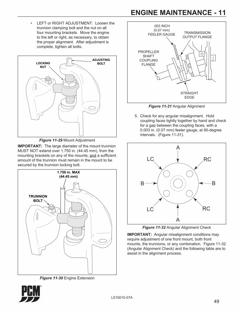
49L510010-07A
ENGINE MAINTENANCE - 11
Figure 11-30 Engine Extension
TRUNNIONBOLT
1.750 in. MAX(44.45 mm)
Figure 11-29 Mount Adjustment
LOCKING
NUT
ADJUSTING
BOLT
• LEFT or RIGHT ADJUSTMENT: Loosen the trunnion clamping bolt and the nut on all four mounting brackets. Move the engine to the left or right, as necessary, to obtain the proper alignment. After adjustment is complete, tighten all bolts.
IMPORTANT: The large diameter of the mount trunnion MUST NOT extend over 1.750 in. (44.45 mm), from the mounting brackets on any of the mounts; and a suffi cient amount of the trunnion must remain in the mount to be secured by the trunnion locking bolt.
Figure 11-31 Angular Alignment
STRAIGHT
EDGE
TRANSMISSION
OUTPUT FLANGE
.003 INCH
(0.07 mm)
FEELER GAUGE
PROPELLER
SHAFT
COUPLING
FLANGE
5. Check for any angular misalignment. Hold coupling faces tightly together by hand and check for a gap between the coupling faces, with a 0.003 in. (0.07 mm) feeler gauge, at 90-degree intervals. (Figure 11-31).
Figure 11-32 Angular Alignment Check
A
A
B B
RC
RC
LC
LC
IMPORTANT: Angular misalignment conditions may require adjustment of one front mount, both front mounts, the trunnions, or any combination. Figure 11-32 (Angular Alignment Check) and the following table are to assist in the alignment process.
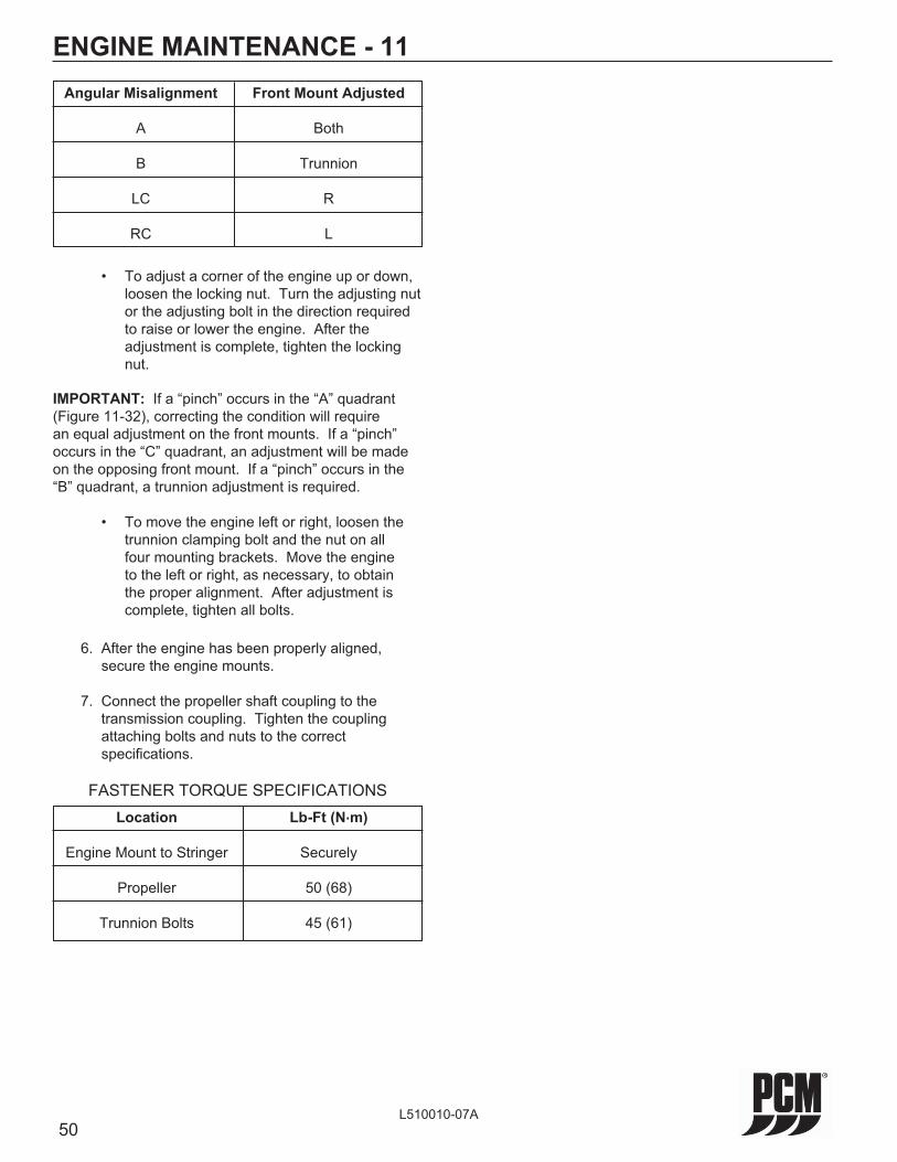
50L510010-07A
ENGINE MAINTENANCE - 11
6. After the engine has been properly aligned, secure the engine mounts.
7. Connect the propeller shaft coupling to the transmission coupling. Tighten the coupling attaching bolts and nuts to the correct specifi cations.
FASTENER TORQUE SPECIFICATIONS Location Lb-Ft (N.m)
Engine Mount to Stringer Securely
Propeller 50 (68)
Trunnion Bolts 45 (61)
Angular Misalignment Front Mount Adjusted
A Both
B Trunnion
LC R
RC L
• To adjust a corner of the engine up or down, loosen the locking nut. Turn the adjusting nut or the adjusting bolt in the direction required to raise or lower the engine. After the adjustment is complete, tighten the locking nut.
IMPORTANT: If a “pinch” occurs in the “A” quadrant (Figure 11-32), correcting the condition will require an equal adjustment on the front mounts. If a “pinch” occurs in the “C” quadrant, an adjustment will be made on the opposing front mount. If a “pinch” occurs in the “B” quadrant, a trunnion adjustment is required.
• To move the engine left or right, loosen the trunnion clamping bolt and the nut on all four mounting brackets. Move the engine to the left or right, as necessary, to obtain the proper alignment. After adjustment is complete, tighten all bolts.
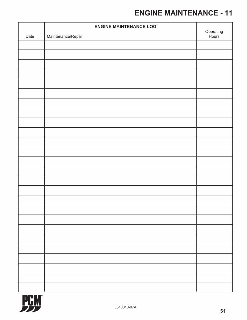
51L510010-07A
ENGINE MAINTENANCE - 11ENGINE MAINTENANCE LOG
Operating Date Maintenance/Repair Hours

52L510010-07A
ENGINE MAINTENANCE - 11MAINTENANCE SCHEDULE
After 1st Every 50 Every 100 Location and Service Check 25 Hrs of Hours of Hours of Once Daily Operation Operation Operation Each Year
Check coolant level - Fresh-water cooled models only X
Check oil level - Engine crankcase X
Check oil level - Transmission X
Engine Assembly (complete - Check for obvious leaks (water, oil, fuel and exhaust) X
Remote Control and Steering System - Check for proper operation X
Sea Strainer - Check (if equipped) X
Cooling System - Check condition and tightness of all hose clamps X X1 X
Cooling System - Inspect/Replace raw water pump impeller X X
Drive Belt - Inspect condition and check tension X X X
Exhaust System - Check condition and tightness of all hose clamps X X1 X
Exhaust System - Check for water leaks at the manifold, riser and elbow gaskets X
Ignition System and Spark Plugs - Clean and inspect condition O O O
Engine Assembly (complete) - Check for loose, missing or damaged parts (especially engine mounts, starter and alternator mounting fasteners) X X X
Change engine oil and fi lter X X X
Engine Alignment - Check and adjust if necessary O O
Ignition Timing - Not Adjustable
Battery - Check electrolyte level and specifi c gravity. Inspect case for damage. Check cables and connections. X X X
Electrical System (complete) - Check for loose or dirty connections and damaged wiring X2 X
Flame Arrestor and Crankcase Ventilation System - Clean and inspect X X

53L510010-07A
ENGINE MAINTENANCE - 11MAINTENANCE SCHEDULE (cont’d)
After 1st Every 50 Every 100 Location and Service Check 25 Hrs of Hours of Hours of Once Daily Operation Operation Operation Each Year
Hoses (all) - Inspect for cracks, swelling, weather checking or other signs of deterioration X X
Shift and Throttle Cable Linkage - Inspect and lubricate (A) X1 X
Fuel Filters - Service or replace O O O
Transmission - Change fl uid (B) and clean strainer, if equipped O O
‘V’-Drive Transmissions - Change fl uid (C) and clean strainer, if equipped O O
MAINTENANCE SCHEDULE (cont’d) Fresh-water cooled models - Clean sea-water section As required 3 (X)
Fresh-water cooled models - Check coolant for alkalinity At least once each year (X)
Fresh-water cooled models - Change coolant Every fi ve years
Zinc Anodes - Heat exchanger and cooler - check condition Every 30 days 3 (X)
Engine Assembly Exterior Surfaces - spray with rust- Fresh water areas - Every 60 days (X) preventative oil (D) Salt water areas - Every 30 days (X)
Cooling System (SALT WATER AREAS ONLY) - Flush sea-water section After use each day (X)
Notes:(X) Denotes service to be performed by the owner/
operator(O) Denotes service to be performed by an authorized
PCM Engines dealer(A) Use SAE 30 engine oil(B) All PCM, Velvet Drive and Hurth transmissions - Use
Dexron III automatic transmission fl uid(C) All PCM Power-Plus “V” Drive transmissions are
designed to be ‘Maintenance Free’. Inspect fl uid level after the fi rst 25 hours of use and annually thereafter. Fluid should only be changed if evidence of contamination is present. Use Mobiltrans SHC 50 synthetic transmission lubricant. PCM P/N: R190250
All Walters “V” Drive transmissions - Use Exxon Spartan EP-68 or SAE 30 engine oil
All Velvet “V” Drive transmissions - Use Dexron III automatic transmission fl uid
(D) Use WD-40 penetration oil or equivalent
1 In fresh-water areas, every 100 hours of operation or 120 days (whichever occurs fi rst). In salt-water areas, every 50 hours of operation or 60 days (whichever occurs fi rst).
2 In fresh-water areas, every 50 hours of operation or 60 days (whichever occurs fi rst). In salt-water areas, every 25 hours of operation or 30 days (whichever occurs fi rst).
3 Requires more frequent inspection if used in extremely salty, polluted or mineral-laden waters.
4 See COOLANT SPECIFICATIONS.
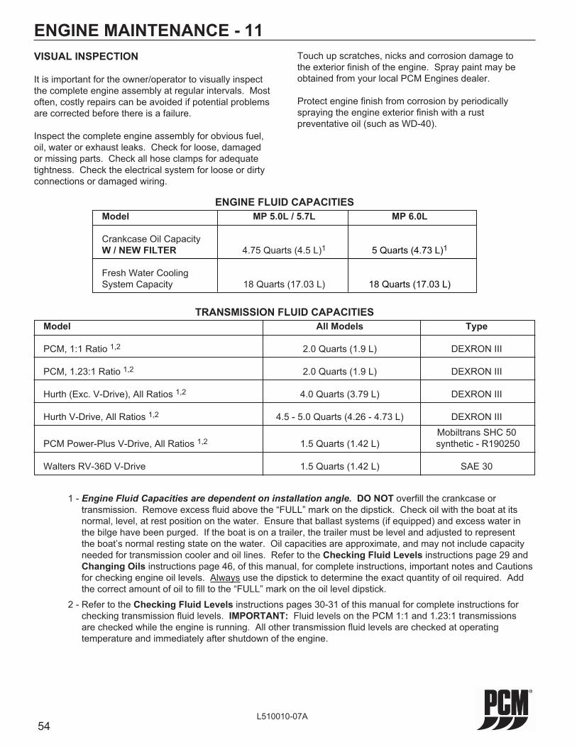
54L510010-07A
VISUAL INSPECTION
It is important for the owner/operator to visually inspect the complete engine assembly at regular intervals. Most often, costly repairs can be avoided if potential problems are corrected before there is a failure.
Inspect the complete engine assembly for obvious fuel, oil, water or exhaust leaks. Check for loose, damaged or missing parts. Check all hose clamps for adequate tightness. Check the electrical system for loose or dirty connections or damaged wiring.
ENGINE MAINTENANCE - 11
TRANSMISSION FLUID CAPACITIES Model All Models Type
PCM, 1:1 Ratio 1,2 2.0 Quarts (1.9 L) DEXRON III
PCM, 1.23:1 Ratio 1,2 2.0 Quarts (1.9 L) DEXRON III Hurth (Exc. V-Drive), All Ratios 1,2 4.0 Quarts (3.79 L) DEXRON III
Hurth V-Drive, All Ratios 1,2 4.5 - 5.0 Quarts (4.26 - 4.73 L) DEXRON III Mobiltrans SHC 50 PCM Power-Plus V-Drive, All Ratios 1,2 1.5 Quarts (1.42 L) synthetic - R190250
Walters RV-36D V-Drive 1.5 Quarts (1.42 L) SAE 30
1 - Engine Fluid Capacities are dependent on installation angle. DO NOT overfi ll the crankcase or transmission. Remove excess fl uid above the “FULL” mark on the dipstick. Check oil with the boat at its normal, level, at rest position on the water. Ensure that ballast systems (if equipped) and excess water in the bilge have been purged. If the boat is on a trailer, the trailer must be level and adjusted to represent the boat’s normal resting state on the water. Oil capacities are approximate, and may not include capacity needed for transmission cooler and oil lines. Refer to the Checking Fluid Levels instructions page 29 and Changing Oils instructions page 46, of this manual, for complete instructions, important notes and Cautions for checking engine oil levels. Always use the dipstick to determine the exact quantity of oil required. Add the correct amount of oil to fi ll to the “FULL” mark on the oil level dipstick.
2 - Refer to the Checking Fluid Levels instructions pages 30-31 of this manual for complete instructions for checking transmission fl uid levels. IMPORTANT: Fluid levels on the PCM 1:1 and 1.23:1 transmissions are checked while the engine is running. All other transmission fl uid levels are checked at operating temperature and immediately after shutdown of the engine.
Touch up scratches, nicks and corrosion damage to the exterior fi nish of the engine. Spray paint may be obtained from your local PCM Engines dealer.
Protect engine fi nish from corrosion by periodically spraying the engine exterior fi nish with a rust preventative oil (such as WD-40).
ENGINE FLUID CAPACITIES Model MP 5.0L / 5.7L MP 6.0L
Crankcase Oil Capacity W / NEW FILTER 4.75 Quarts (4.5 L)1 5 Quarts (4.73 L)1 Fresh Water Cooling System Capacity 18 Quarts (17.03 L) 18 Quarts (17.03 L)

55L510010-07A
ENGINE MAINTENANCE - 11FILTER REQUIREMENTS
Description Part No.
Oil Filter (remote-mounted) R077001
Kit, Transmission Oil Filter (ZF) RP077011
Primary Fuel Filter R080024
Fuel Control Cell (FCC) Fuel Filter Element RP080026
PCM BASIC CRUISE SPEED CONTROL SYSTEM Description Part No.
PCM Basic Cruise Control Panel RA152008
Speed Control Interface Harness - 14 Ft RA121091B
PCM POWER-PLUS V-DRIVE LUBRICANT Description Part No.
PCM Power-Plus V-Drive Lubricant (1 qt. bottle) R190250
PN: R080024
INOUT
RP080026
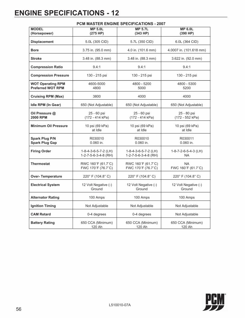
56L510010-07A
ENGINE SPECIFICATIONS - 12
MODEL MP 5.0L MP 5.7L MP 6.0L (Horsepower) (275 HP) (343 HP) (390 HP)
Displacement 5.0L (305 CID) 5.7L (350 CID) 6.0L (364 CID)
Bore 3.75 in. (95.0 mm) 4.0 in. (101.6 mm) 4.0007 in. (101.618 mm)
Stroke 3.48 in. (88.3 mm) 3.48 in. (88.3 mm) 3.622 in. (92.0 mm)
Compression Ratio 9.4:1 9.4:1 9.4:1
Compression Pressure 130 - 215 psi 130 - 215 psi 130 - 215 psi
WOT Operating RPM 4600-5000 4800 - 5200 4800 - 5300 Preferred WOT RPM 4800 5000 5200
Cruising RPM (Max) 3800 4000 4000
Idle RPM (In Gear) 650 (Not Adjustable) 650 (Not Adjustable) 650 (Not Adjustable)
Oil Pressure @ 25 - 60 psi 25 - 60 psi 25 - 80 psi 2000 RPM (172 - 414 kPa) (172 - 414 kPa) (172 - 552 kPa)
Minimum Oil Pressure 10 psi (69 kPa) 10 psi (69 kPa) 10 psi (69 kPa) at Idle at Idle at Idle Spark Plug P/N R030010 R030010 R030011 Spark Plug Gap 0.060 in. 0.060 in. 0.060 in. Firing Order 1-8-4-3-6-5-7-2 (LH) 1-8-4-3-6-5-7-2 (LH) 1-8-7-2-6-5-4-3 (LH) 1-2-7-5-6-3-4-8 (RH) 1-2-7-5-6-3-4-8 (RH) NA
Thermostat RWC 160˚F (61.7˚C) RWC 160˚F (61.7˚C) NA FWC 170˚F (76.7˚C) FWC 170˚F (76.7˚C) FWC 160˚F (61.7˚C)
Over- Temperature 220° F (104.8° C) 220° F (104.8° C) 220° F (104.8° C)
Electrical System 12 Volt Negative (-) 12 Volt Negative (-) 12 Volt Negative (-) Ground Ground Ground
Alternator Rating 100 Amps 100 Amps 100 Amps
Ignition Timing Not Adjustable Not Adjustable Not Adjustable
CAM Retard 0-4 degrees 0-4 degrees Not Adjustable
Battery Rating 650 CCA (Minimum) 650 CCA (Minimum) 650 CCA (Minimum) 120 Ah 120 Ah 120 Ah
PCM MASTER ENGINE SPECIFICATIONS - 2007

57L510010-07A
ENGINE SPECIFICATIONS - 12
MODEL MP 5.0L MP 5.7L MP 6.0L (Horsepower) (275 HP) (343 HP) (390 HP)
Fuel Pressure 57-62 psi @ WOT 57-62 psi @ WOT STD. FCC Fuel Pressure - FCC 57-62 psi Returnless to Rail (WOT)
Fuel Pressure - LPFP 7 - 9 psi 7 - 9 psi 7 - 9 psi ALL ENGINES (WOT) (WOT) (WOT)
PCM MASTER FUEL PRESSURE SPECIFICATIONS - 2007
IMPORTANT: FUEL PRESSURE MEASUREMENT MUST BE MADE WITH THE ENGINE UNDER LOAD.
MODEL MP 5.0L MP 5.7L MP 6.0L (Horsepower) (275 HP) (343 HP) (390 HP) Coolant 220° F (104.8° C) 220° F (104.8° C) 220° F (104.8° C) Over-Temperature M.I.L. - DTC 116 M.I.L. - DTC 116 M.I.L. - DTC 116 Sensor Check Engine Lamp Check Engine Lamp Check Engine Lamp and/or Buzzer and/or Buzzer and/or Buzzer Transmission 235° F ± 10° F 235° F ± 10° F 235° F ± 10° F Over-Temperature M.I.L. - DTC 1542 M.I.L. - DTC 1542 M.I.L. - DTC 1542 Switch Check Engine Lamp Check Engine Lamp Check Engine Lamp Exhaust 248° F ± 5° F 248° F ± 5° F 248° F ± 5° F Over-Temperature M.I.L. - DTC 2428 M.I.L. - DTC 2428 M.I.L. - DTC 2428 Switch Check Engine Lamp Check Engine Lamp Check Engine Lamp and/or Buzzer and/or Buzzer and/or Buzzer Low Oil < 10 psi < 10 psi < 10 psi Pressure Sensor M.I.L. - DTC 524 M.I.L. - DTC 524 M.I.L. - DTC 524 Check Engine Lamp Check Engine Lamp Check Engine Lamp and/or Buzzer and/or Buzzer and/or Buzzer
PCM MASTER WARNING/ALARM SPECIFICATIONS - 2007

58L510010-07A
ENGINE SPECIFICATIONS - 12
Figure 12-1 V-8 Firing Orders
1
3
5
7
2
4
6
8
1
3
5
7
2
4
6
8
5.0 / 5.7 LiterLH ROTATION
FRONT
6.0 LiterLH ROTATION
FRONT
NODISTRIBUTOR
FIRING ORDER:1-8-4-3-6-5-7-2
FIRING ORDER:1-8-7-2-6-5-4-3
FLYWHEEL END OF ENGINEALL V-8 MODELS
17
c
64
28
35
Rotation
TUNE-UP SPECIFICATIONS Model MP 5.0L (275 HP) MP 5.7L (343 HP) MP 6.0L (390 HP)
Spark Plug Type R030010 R030011
Spark Plug Gap 0.060 in. 0.060 in. (1.52 mm) (1.52 mm)
Ignition Timing Fixed, Fixed, Not Adjustable Not Adjustable
Firing Order 1-8-4-3-6-5-7-2 1-8-7-2-6-5-4-3 (LH Rotation) (LH Rotation)
CAM Retard 0-4 degrees Not Adjustable

59L510010-07A
OUT-OF-SEASON STORAGE - 13ENGINE STORAGE
IMPORTANT: This service should be performed by an Authorized PCM Dealer.
CAUTION
Refer to FLUSHING COOLING SYSTEM before proceeding.
1. Fill the fuel tanks with gasoline and add a suffi cient amount of gasoline stabilizer, such as STA-BIL™ fuel stabilizer, to prevent the formation of fuel gum and varnish. Follow the instructions on the container.
WARNING
Operate the bilge blower and be sure no fuel vapors are present when treating the engine. Be sure the engine compartment is well-ventilated to prevent a potential fi re hazard.
5. Restart the engine and allow it to idle for 5 minutes.
. 6. Turn off the ignition and remove the spark plugs. Use an aerosol-type fogging solution and spray a suffi cient amount of oil into each cylinder. (Follow the instructions for the storage oil used.) Turn the crankshaft several revolutions by hand to spread the oil evenly throughout the cylinders.
WARNING
On fuel injected engines, you MUST bleed off fuel pressure before proceeding. Failure to do so may cause personal injury.
WARNING
Operate the bilge blower and be sure no fuel vapors are present when treating the engine. Be sure the engine compartment is well-ventilated to prevent a potential fi re hazard.
2. Remove, empty and clean the fuel fi lter assembly. Reinstall with a new fuel fi lter and gasket / seals. Refer to Engine Maintenance for fi lter replacement procedures.
NOTE: DO NOT re-use old fuel fi lter components. Always replace with new fuel fi lter element and gasket / seals.
WARNING
Accumulation of water and other fuel contaminants may form corrosive compounds that can damage the fuel fi lter, and result in fuel leakage. Ethanol blended fuel may increase this risk. For this reason, annual replacement of the fuel fi lter, at a minimum, is required to avoid risk of explosion or fi re.
3. Run the engine and allow it to reach normal operating temperature (a minimum of 10 minutes). Shut down the engine and change the oil and oil fi lter (See ENGINE MAINTENANCE).
4. Flush the cooling system if operating in salt water or brackish water areas. (See ENGINE MAINTENANCE).
CAUTION
Excess storage oil in the engine’s cylinders can cause hydrostatic locking to occur, and severe damage to the engine.
7. Install the spark plugs and connect the spark plug wires.
8. Remove and clean the fl ame arrestor and the vent hoses, and reinstall on the engine. Cover the throttle body assembly ,to prevent the possibility of the water entering the engine through the throttle body assembly, during storage.
9. Close the fuel shut-off valve (if equipped).

60L510010-07A
OUT-OF-SEASON STORAGE - 13DRAINING INSTRUCTIONS
CAUTION
If the boat is to remain in the water during or after draining, close the seacock to prevent a siphoning action that may occur, allowing sea water to fl ow from drain holes or removed hoses.
IMPORTANT: When removing the drain plugs, insert a wire into the hole to remove any obstruction which would prevent water from draining completely.
RAW-WATER COOLED MODELS 1. Remove all the drain plugs from the following
locations: • Cylinder Block - one on each side (5.0/5.7L
engines, remove the knock sensor on the port side). When installing the knock sensor, torque to 20 N.m (15 lb ft).
• Exhaust Manifolds - remove hoses and/or drain plugs, one on each side.
• Transmission Cooler - one drain plug. • (If Equipped) PCM V-Drive Transmission
- one drain plug. 2. Remove the hose from the inlet side of the sea-
water pump. 3. Remove the large hose from the engine
circulating pump, or drain plug (if equipped).NOTICE: It may be necessary to bend or lift the hoses to allow water to drain completely. 4. Remove the raw water pump impeller. (See
ENGINE MAINTENANCE) If inspection proves the impeller to be in good condition, store it in an accessible spot for re-installation at the end of the storage period. A damaged or badly worn impeller should be discarded and a new one installed at the end of the storage period.
NOTE: Removal of the impeller during storage will prevent the impeller vanes from drying and taking a permanent “set”. 5. After the water has completely drained, coat the
threads of the drain plugs with PerfectSeal (or equivalent), and reinstall in the proper locations. Reinstall all the hoses and tighten the clamps securely.
6. Loosen the engine alternator and raw water pump drive belt(s).
NOTICE: For additional protection against freezing and corrosion, you may wish to fi ll the engine with antifreeze. If ethylene glycol based antifreeze is used, check with local environmental agencies about the proper disposal of antifreeze. It may be necessary to drain the system prior to re-commissioning the boat. 7. Remove the hoses which connect to the exhaust
manifolds from the thermostat housing.
Figure 13-1 Draining Engine Circulating Pump (5.0/5.7L)
Remove DRAIN PLUG (as equipped)
Figure 13-2 Draining PCM V-Drive Transmission
PLEASURECRAFTENGINE GROUP
POWER PLUSRATIO 1.48
MADE IN USA
Remove Raw WaterDrain Plug
9/16”Hex KeySocket

61L510010-07A
OUT-OF-SEASON STORAGE - 13 8. Remove the large circulating pump hose from
the thermostat housing. Pour the mixture of antifreeze and water, properly mixed to protect the engine to the lowest temperatures that it will be exposed to, into the circulating pump hose and fi ll the engine block. Pour additional antifreeze solution into the hoses connected to the exhaust manifolds.
9. Reinstall the hoses into the thermostat housing and tighten the hose clamps securely.
After draining is completed, perform the additional required maintenance as outlined in the MAINTENANCE SCHEDULE under ONCE EACH YEAR.
CAUTION
A discharged battery can be damaged by freezing.
IMPORTANT: When removing the drain plugs, insert a wire into the hole to remove any obstruction which would prevent water from draining completely.
FRESH-WATER COOLED MODELS
IMPORTANT: The fresh-water section of the cooling system must be kept fi lled year around with recommended coolant. Make certain that the cooling system is protected with an ethylene glycol antifreeze mixture properly mixed to protect the engine to the lowest temperature that it will be exposed to.
See the ENGINE MAINTENANCE section for testing alkalinity, draining and refi lling procedures of the Fresh Water Cooling System, as required.
IMPORTANT: Drain the sea-water section of the cooling system only. 1. Remove all the drain plugs from the following
locations: • Heat Exchanger - one on outboard side • Exhaust Manifolds - remove hoses and/or
drain plugs, one on each side • Transmission Cooler - one drain plug • (If Equipped) PCM V-Drive Transmission
- one drain plug.
2. Remove the hose from the inlet side of the sea-water pump.
3. Remove the hose from the outlet side of the sea-water pump.
NOTICE: It may be necessary to bend or lift the hoses to allow water to drain completely. 4. Remove the raw water pump impeller. (See
ENGINE MAINTENANCE) If inspection proves the impeller to be in good condition, store it in an accessible spot for re-installation at the end of the storage period. A damaged or badly worn impeller should be discarded and a new one installed at the end of the storage period.
NOTE: Removal of the impeller during storage will prevent the impeller vanes from drying and taking a permanent “set”. 5. After the water has completely drained, coat
the threads of drain plugs with PerfectSeal (or equivalent), and reinstall in the proper locations. Reinstall the hoses and tighten all the clamps securely.
6. Loosen the engine alternator and raw water pump drive belt(s).
After draining is completed, perform the additional required maintenance as outlined in the MAINTENANCE SCHEDULE under ONCE EACH YEAR.
BATTERY STORAGEFollow the battery manufacturer’s instructions for storage. If not available, use the following instructions: • Remove the battery from the boat and clean,
removing dirt and grease from the top of the battery.
• Fill the battery with distilled water to the manufacturer’s specifi cations.
• Store the battery in a cool, dry place. Do not store on a concrete surface.
• Periodically (every 30 to 45 days), check the water level and recharge the battery to the manufacturer’s specifi cations. Do not fast charge.
CAUTION
If the boat is to remain in the water during or after draining, close the seacock to prevent a siphoning action that may occur, allowing sea water to fl ow from drain holes or removed hoses.
DRAINING INSTRUCTIONS

62L510010-07A
OUT-OF-SEASON STORAGE - 13
CAUTION
When installing the battery, make certain that you connect the POSITIVE (+) BATTERY CABLE to the POSITIVE (+) BATTERY TERMINAL fi rst, and the NEGATIVE (-) BATTERY CABLE to the NEGATIVE (-) BATTERY TERMINAL last. If the battery cables are reversed, the electrical system will be damaged.
RECOMMISSIONING AFTER STORAGE
IMPORTANT: These services should be performed by an Authorized PCM Dealer.
When recommissioning the engine after storage, the following items should be checked:
1. Assemble the raw water pump and reinstall on the engine.
2. Check all the cooling system hoses. Be sure they are properly connected and all the hose clamps are tight.
WARNING
Do not use jumper cables and/or a booster battery to start the engine. Do not recharge a weak battery in the boat. Remove the battery and recharge in a ventilated area away from fuel vapors, sparks or open fl ame.
3. Install the fully charged battery. Be sure that all the connections are clean and free from corrosion. Coat the battery terminal connections with an anti-corrosion battery terminal spray.
4. Readjust alternator and water pump drive belt tension.
5. Check engine alignment.
6. Check engine and transmission oil levels.
7. Check engine mount fasteners.
CAUTION
If the engine(s) is (are) to be started prior to launching, use the procedure FLUSHING COOLING SYSTEM before proceeding to start the engine(s).
11. Open the seacock before starting the engine.
12. Start the engine and closely observe the instrument panel. Allow the engine to reach normal operating temperature. Inspect the engine carefully for fuel, exhaust, oil and water leaks.
13. Check the steering, shift and throttle controls for proper operation.
8. Open the fuel shut-off valve (if equipped).
9. Refer to the OPERATING INSTRUCTIONS section and perform all the safety checks before starting the engine.
10. Refer to the Engine Maintenance section and perform the Priming the Fuel System instructions.
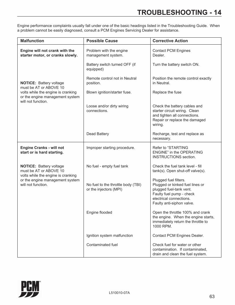
63L510010-07A
TROUBLESHOOTING - 14
Engine performance complaints usually fall under one of the basic headings listed in the Troubleshooting Guide. When a problem cannot be easily diagnosed, consult a PCM Engines Servicing Dealer for assistance.
Malfunction Possible Cause Corrective Action
Engine will not crank with the Problem with the engine Contact PCM Engines starter motor, or cranks slowly. management system. Dealer.
Battery switch turned OFF (if Turn the battery switch ON. equipped)
Remote control not in Neutral Position the remote control exactly NOTICE: Battery voltage position. in Neutral. must be AT or ABOVE 10 volts while the engine is cranking Blown ignition/starter fuse. Replace the fuse or the engine management system will not function. Loose and/or dirty wiring Check the battery cables and connections. starter circuit wiring. Clean and tighten all connections. Repair or replace the damaged wiring.
Dead Battery Recharge, test and replace as necessary.
Engine Cranks - will not Improper starting procedure. Refer to “STARTING start or is hard starting. ENGINE” in the OPERATING INSTRUCTIONS section.
NOTICE: Battery voltage No fuel - empty fuel tank Check the fuel tank level - fi ll must be AT or ABOVE 10 tank(s). Open shut-off valve(s). volts while the engine is cranking or the engine management system Plugged fuel fi lters. will not function. No fuel to the throttle body (TBI) Plugged or kinked fuel lines or or the injectors (MPI) plugged fuel-tank vent. Faulty fuel pump - check electrical connections. Faulty anti-siphon valve.
Engine fl ooded Open the throttle 100% and crank the engine. When the engine starts, immediately return the throttle to 1000 RPM.
Ignition system malfunction Contact PCM Engines Dealer.
Contaminated fuel Check fuel for water or other contamination. If contaminated, drain and clean the fuel system.

64L510010-07A
TROUBLESHOOTING - 14 Malfunction Possible Cause Corrective Action
Engine Overheats Loose or worn drive belt(s) Adjust or replace the belts as necessary.
Collapsed, kinked or leaking Replace the hoses. hoses.
Transmission/engine oil cooler Remove the water hoses and fl ush plugged in opposite direction of the normal fl ow.
Faulty thermostat Replace the thermostat. Sea-water intake valve Open the valve completely. partially/fully closed. Restricted sea-water pickup Remove restriction. Faulty temperature sending unit Test and replace as necessary. or gauge
Sea-water pump impeller worn or Replace the impeller. damaged
The following applies to engines Coolant level low in the fresh-water Check the cooling system for leaks. equipped with Fresh-Water section of the cooling system Refi ll the system. See Warning Cooling (FWC) systems. before removing the fi ll cap.
Heat exchanger passages plugged Clean and fl ush the exchanger. with scales and debris
Improper coolant mixture Install the proper coolant mixture (50% antifreeze - 50% water).
Insuffi cient engine temperature Faulty thermostat Replace the thermostat. Faulty temperature sender Replace the temperature sender.
Engine oil pressure low Faulty oil pressure sending unit Test and replace as necessary. or gauge
Oil level low Add specifi ed oil. Check the engine for leaks. Crankcase overfi lled causing oil Remove the required amount of oil. aeration Determine the cause of overfi lled condition (improper fi lling, etc.). Diluted or improper grade/ Change the oil and fi lter. viscosity of oil Determine the cause of dilution. (insuffi cient engine temperature, excessive idling, etc.)

65L510010-07A
TROUBLESHOOTING - 14 Malfunction Possible Cause Corrective Action
Transmission slipping - Low oil level Add specifi ed oil. Check the erratic operation transmission for leaks.
Transmission overfi lled causing Drain required amount of oil. oil aeration
Transmission shift lever not fully Adjust the shift linkage and remote engaged control. Check the shift cables for freedom of movement and binding.
Contaminated fl uid Determine and correct the contamination source and change the fl uid. Engine misses, runs rough Ignition system malfunction Contact PCM Engines Dealer. and/or backfi res Plugged fuel fi lters Replace the fuel fi lters. Faulty fuel pump. Have fuel pump replaced by a PCM Engines Dealer/
Plugged or kinked fuel lines or Repair or replace the fuel lines. fuel tank vent Remove obstruction.
Anti-siphon valve faulty Clean or replace as necessary. Flame arrestor dirty Clean the fl ame arrestor.
Poor engine or boat Ignition malfunction Contact PCM Engines Dealer. performance Throttle not fully open Check the remote control and throttle body linkage for freedom of movement and proper adjustment.
Damaged or improper propeller Repair or replace as necessary. Excessive water in the bilge Pump the water out and investigate source of entry. Excessive growth on the boat Clean the bottom and paint with an bottom anti-fouling paint. Boat overloaded Reduce and/or redistribute the load. Dirty fl ame arrestor Clean the fl ame arrestor. Engine overheating Repair the cooling system (See “Engine Overheats”).
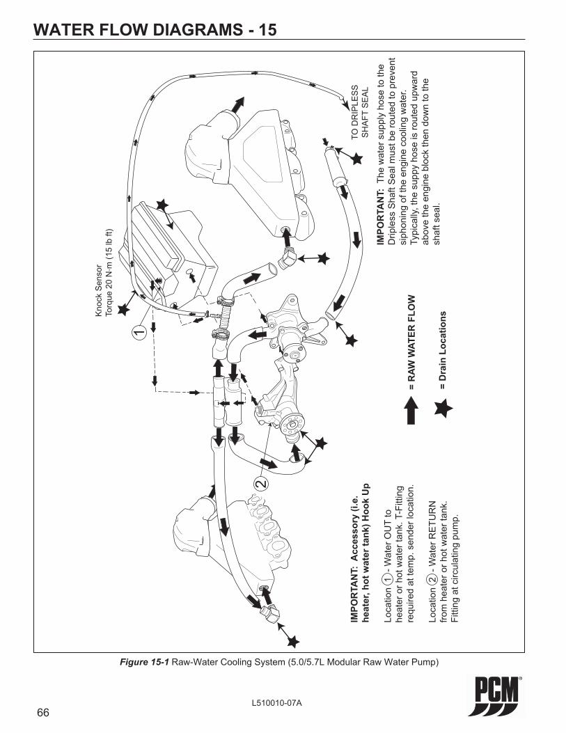
66L510010-07A
WATER FLOW DIAGRAMS - 15
= R
AW W
ATER
FLO
W
= D
rain
Loc
atio
nsKno
ck S
enso
rTo
rque
20
N. m
(15
lb ft
)
IMPO
RTA
NT:
Acc
esso
ry (i
.e.
heat
er, h
ot w
ater
tank
) Hoo
k U
p
Loca
tion
1 -
Wat
er O
UT
to
heat
er o
r hot
wat
er ta
nk. T
-Fitt
ing
requ
ired
at te
mp.
sen
der l
ocat
ion.
Loca
tion
2 -
Wat
er R
ETU
RN
fro
m h
eate
r or h
ot w
ater
tank
. Fi
tting
at c
ircul
atin
g pu
mp.
2
1
TO D
RIP
LES
SS
HA
FT S
EA
L
IMPO
RTA
NT:
The
wat
er s
uppl
y ho
se to
the
Drip
less
Sha
ft S
eal m
ust b
e ro
uted
to p
reve
ntsi
phon
ing
of th
e en
gine
coo
ling
wat
er.
Typi
cally
, the
sup
py h
ose
is ro
uted
upw
ard
abov
e th
e en
gine
blo
ck th
en d
own
to th
e sh
aft s
eal.
Figure 15-1 Raw-Water Cooling System (5.0/5.7L Modular Raw Water Pump)

67L510010-07A
WATER FLOW DIAGRAMS - 15
Figure 15-2 Fresh-Water Cooling System (5.0/5.7L)
= R
AW W
ATER
FLO
W
= FR
ESH
WAT
ER F
LOW
= D
rain
Loc
atio
ns
1
2
2
IMPO
RTA
NT:
Acc
esso
ry (i
.e.
heat
er, h
ot w
ater
tank
) Hoo
k U
p
Loca
tion
1 -
Wat
er O
UT
to
heat
er o
r hot
wat
er ta
nk. T
-Fitt
ing
requ
ired
at te
mp.
sen
der l
ocat
ion.
Loca
tion
2 -
Wat
er R
ETU
RN
fro
m h
eate
r or h
ot w
ater
tank
. Fi
tting
at b
otto
m o
f hea
t ex
chan
ger O
R c
irc. p
ump.
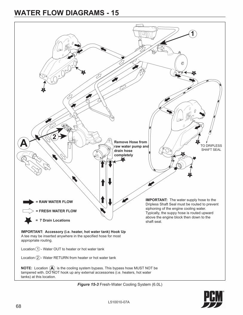
68L510010-07A
Figure 15-3 Fresh-Water Cooling System (6.0L)
WATER FLOW DIAGRAMS - 15
= RAW WATER FLOW
NOTE: Location is the cooling system bypass. This bypass hose MUST NOT be tampered with. DO NOT hook up any external accessories (i.e. heaters, hot water tanks) at this location.
IMPORTANT: Accessory (i.e. heater, hot water tank) Hook UpA tee may be inserted anywhere in the specified hose for most appropriate routing.
Location 1 - Water OUT to heater or hot water tank
Location 2 - Water RETURN from heater or hot water tank
= FRESH WATER FLOW
A
A
1
2
= 7 Drain Locations
Remove Hose from raw water pump and drain hose completely
3
2
4
5
6
7
1
TO DRIPLESSSHAFT SEAL
IMPORTANT: The water supply hose to theDripless Shaft Seal must be routed to preventsiphoning of the engine cooling water. Typically, the suppy hose is routed upward above the engine block then down to the shaft seal.

69L510010-07A
WATER FLOW DIAGRAMS - 15
= Optional Drain Kit
The drain kit does not ensure that all of the
water will drain out of the system. Engine
angle, routing of drain hose, and restricted
drain fittings are some things that could
prevent all of the water from draining
completely.
DRAIN
Figure 15-4 Water Drain kit - Optional (6.0L)
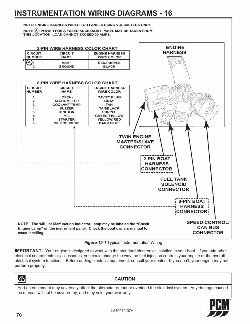
70L510010-07A
INSTRUMENTATION WIRING DIAGRAMS - 16
Figure 16-1 Typical Instrumentation Wiring
NOTE: ENGINE HARNESS WIRED FOR PANELS USING VOLTMETERS ONLY.
NOTE A : POWER FOR A FUSED ACCESSORY PANEL MAY BE TAKEN FROMTHIS LOCATION. LOAD CANNOT EXCEED 30 AMPS.
CIRCUIT CIRCUIT ENGINE HARNESS NUMBER NAME WIRE COLOR
1. VBAT RED/PURPLE 2. GROUND BLACK
2-PIN WIRE HARNESS COLOR CHART
A
ENGINEHARNESS
SPEED CONTROL/CAN BUS
CONNECTOR
FUEL TANK SOLENOID
CONNECTOR
TWIN ENGINE MASTER/SLAVE
CONNECTOR
2-PIN BOAT HARNESS
CONNECTOR
8-PIN BOAT HARNESS
CONNECTOR
CIRCUIT CIRCUIT ENGINE HARNESS NUMBER NAME WIRE COLOR
1. (OPEN) CAVITY PLUG 2. TACHOMETER GRAY 3. COOLANT TEMP TAN 4. BUZZER TAN/BLACK 5. IGNITION PURPLE 6. MIL GREEN/YELLOW 7. STARTER YELLOW/RED 8. OIL PRESSURE DARK BLUE
8-PIN WIRE HARNESS COLOR CHART
NOTE: The ‘MIL’ or Malfunction Indicator Lamp may be labeled the “Check Engine Lamp” on the instrument panel. Check the boat owners manual for exact labelling.
IMPORTANT: Your engine is designed to work with the standard electronics installed in your boat. If you add other electrical components or accessories, you could change the way the fuel injection controls your engine or the overall electrical system functions. Before adding electrical equipment, consult your dealer. If you don’t, your engine may not perform properly.
CAUTION
Add-on equipment may adversely affect the alternator output or overload the electrical system. Any damage caused as a result will not be covered by, and may void, your warranty.
71L510010-07A
LITERATURE - 17To obtain service and/or parts literature for your PCM Marine Engine, contact the following:
1. SERVICE: For more detailed information, PCM has a detailed service manual available. This manual contains complete engine and component disassembly and reassembly instructions. Troubleshooting and maintenance charts are also included.
2. PARTS: Parts manuals with exploded views for service parts are available for all current engine models.
IMPORTANT: When contacting the factory for service information, be sure to include your engine model and serial number to insure the service information you receive is correct.
PCM EnginesPleasurecraft Engine Group
Publications Department1737 Highway 76 East
Little Mountain, SC 29075
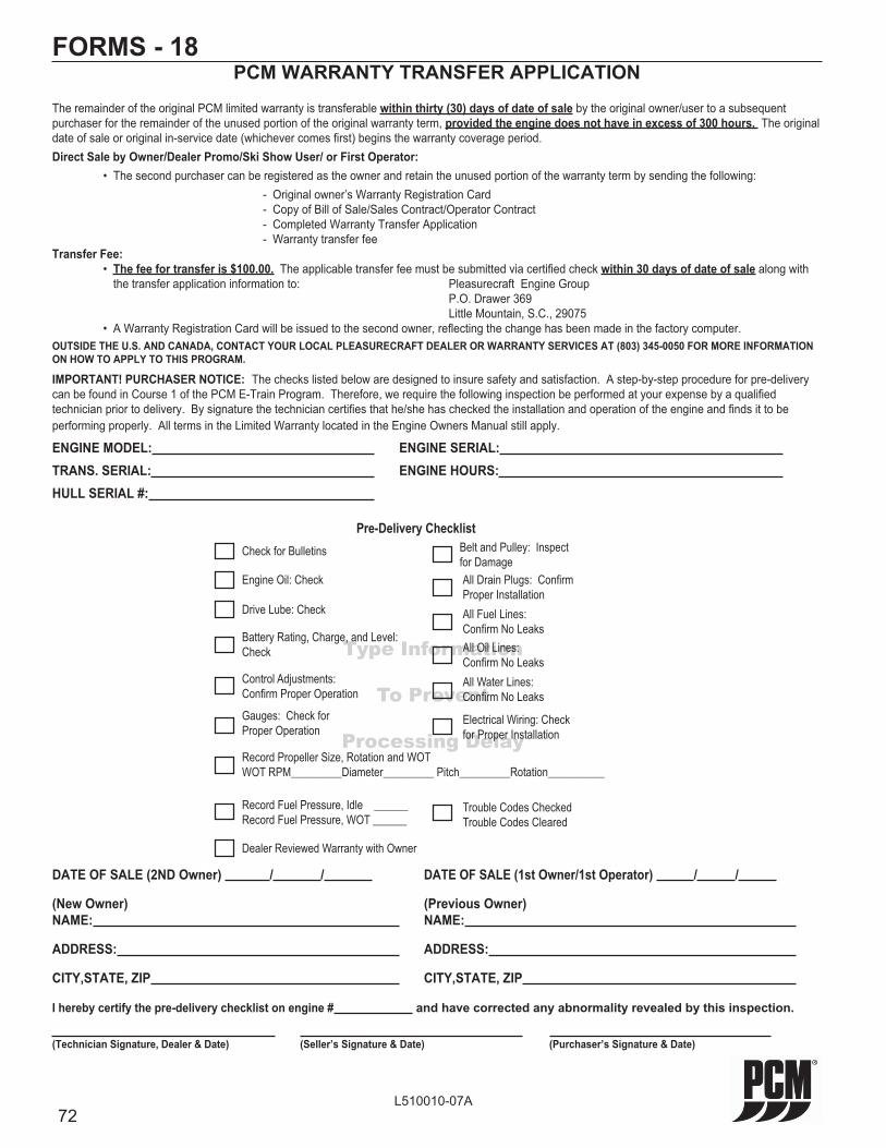
72L510010-07A
FORMS - 18PCM WARRANTY TRANSFER APPLICATION
The remainder of the original PCM limited warranty is transferable within thirty (30) days of date of sale by the original owner/user to a subsequent purchaser for the remainder of the unused portion of the original warranty term, provided the engine does not have in excess of 300 hours. The original date of sale or original in-service date (whichever comes fi rst) begins the warranty coverage period.Direct Sale by Owner/Dealer Promo/Ski Show User/ or First Operator: • The second purchaser can be registered as the owner and retain the unused portion of the warranty term by sending the following: - Original owner’s Warranty Registration Card - Copy of Bill of Sale/Sales Contract/Operator Contract - Completed Warranty Transfer Application - Warranty transfer feeTransfer Fee: • The fee for transfer is $100.00. The applicable transfer fee must be submitted via certifi ed check within 30 days of date of sale along with
the transfer application information to: Pleasurecraft Engine Group P.O. Drawer 369 Little Mountain, S.C., 29075 • A Warranty Registration Card will be issued to the second owner, refl ecting the change has been made in the factory computer.OUTSIDE THE U.S. AND CANADA, CONTACT YOUR LOCAL PLEASURECRAFT DEALER OR WARRANTY SERVICES AT (803) 345-0050 FOR MORE INFORMATION ON HOW TO APPLY TO THIS PROGRAM.
IMPORTANT! PURCHASER NOTICE: The checks listed below are designed to insure safety and satisfaction. A step-by-step procedure for pre-delivery can be found in Course 1 of the PCM E-Train Program. Therefore, we require the following inspection be performed at your expense by a qualifi ed technician prior to delivery. By signature the technician certifi es that he/she has checked the installation and operation of the engine and fi nds it to be performing properly. All terms in the Limited Warranty located in the Engine Owners Manual still apply.
ENGINE MODEL: ENGINE SERIAL: TRANS. SERIAL: ENGINE HOURS: HULL SERIAL #:
DATE OF SALE (2ND Owner) / / DATE OF SALE (1st Owner/1st Operator) / /
(New Owner) (Previous Owner)NAME: NAME:
ADDRESS: ADDRESS:
CITY,STATE, ZIP CITY,STATE, ZIP
I hereby certify the pre-delivery checklist on engine # and have corrected any abnormality revealed by this inspection.
(Technician Signature, Dealer & Date) (Seller’s Signature & Date) (Purchaser’s Signature & Date)
Type Information
To Prevent
Processing Delay
Pre-Delivery ChecklistCheck for Bulletins
Engine Oil: Check
Drive Lube: Check All Fuel Lines: Confi rm No Leaks
All Water Lines: Confi rm No Leaks
Battery Rating, Charge, and Level: Check
Control Adjustments:Confi rm Proper Operation
All Drain Plugs: Confi rm Proper Installation
Belt and Pulley: Inspect for Damage
Gauges: Check for Proper Operation
Record Propeller Size, Rotation and WOTWOT RPM_________Diameter_________ Pitch_________Rotation__________
Record Fuel Pressure, Idle ______Record Fuel Pressure, WOT ______
Trouble Codes CheckedTrouble Codes Cleared
Dealer Reviewed Warranty with Owner
Electrical Wiring: Check for Proper Installation
All Oil Lines: Confi rm No Leaks

73L510010-07A
FORMS - 18PCM
SUMMARY OF WARRANTY TERM LIMITS
This list does not, in any way, modify the offi cial Limited Warranty Statement of PCM. This list has been compiled only as a general outline of year and hour limits imposed on different models of PCM engines. Please review the offi cial Limited Warranty Statements on the following pages for specifi c terms and limitations as they apply to the particular engine / component involved.
ENGINE MODEL YEAR: WARRANTY COVERAGE TERM:2004*** 3 years, unlimited hours, GM. 3 years, unlimited hours Transmission2005*** 3 years, unlimited hours, GM. 3 years, unlimited hours Transmission2006*** 3 years, unlimited hours, GM. 3 years, unlimited hours Transmission2007*** 3 years, unlimited hours, GM. 3 years, unlimited hours TransmissionBase Engine 1 year, 200 hours with exclusions.Note: *** 2004-2007 Model Year Engines: The remainder of the original PCM limited warranty is transferable to a subse-
quent purchaser, provided the engine does not have in excess of 300 hours and is submitted to PCM within 30 days of the date of sale.
PCM OWNERSHIP CHANGE NOTICE
If you are the new owner of a Pleasurecraft Marine Engine on which the warranty has expired and would like to inform Pleasurecraft of your ownership for notifi cation purposes in case of Service Updates, Recalls, etc., complete the section below and return by mail to PCM. PO Drawer 369, Little Mountain, SC 29075.
ENGINE MODEL: _________________________
ENGINE SERIAL NUMBER: _________________________
TRANS. MODEL: _________________________
TRANS. SERIAL NUMBER: _________________________
(New Owner) NAME: _____________________________________________________________________________
ADDRESS:______________________________________________________________________________________________________________
CITY,STATE,ZIP: ________________________________________________________________________________
DATE OF PURCHASE: ___________________________________________________________________________
(Previous Owner)NAME: _________________________________________________________________________
ADDRESS: _____________________________________________________________________________________
CITY,STATE,ZIP: ________________________________________________________________________________
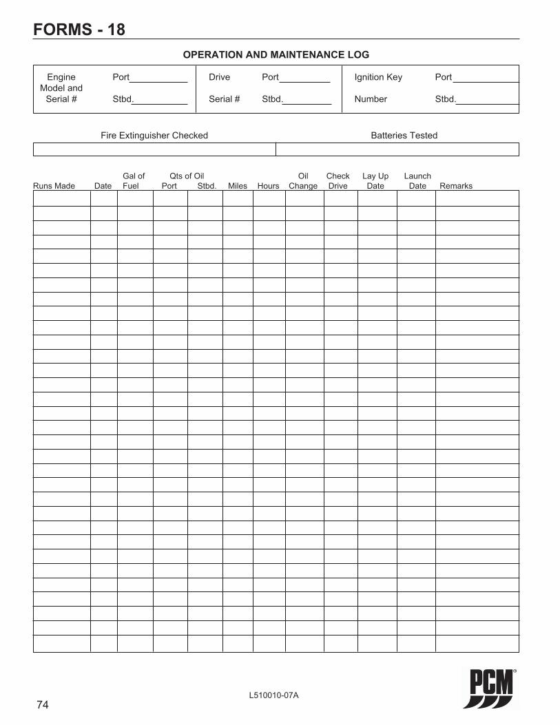
74L510010-07A
FORMS - 18OPERATION AND MAINTENANCE LOG
Engine Port Drive Port Ignition Key Port Model and Serial # Stbd. Serial # Stbd. Number Stbd.
Fire Extinguisher Checked Batteries Tested
Gal of Qts of Oil Oil Check Lay Up Launch Runs Made Date Fuel Port Stbd. Miles Hours Change Drive Date Date Remarks

75L510010-07A
FORMS - 18PROBLEM NOTIFICATION OR INFORMATION REQUEST FORM
IMPORTANT: All blanks MUST be completed to insure proper identifi cation of your engine which is necessary to properly understand your request.
When completed, mail this form to: Pleasurecraft Marine PO Drawer 369 Little Mountain, SC 29075
Engine Model Engine Serial Number Gear Serial Number
Owner Information
Name Telephone ( )AddressCity State ZipSelling DealerDealers AddressDate of Purchase Boat Make Length Type
Gentlemen, I would like to inform you of a problem I have experienced with the above engine. My problem is:
My boat is located atAddress Telephone ( )City State ZipRequestors Signature Date

76L510010-07A
This Page Was
Intentionally
Left Blank

77L510010-07A
NOTES - 19

Pleasurecraft Engine Group 1737 Highway 76 East, Little Mountain SC 29075