operation, maintenance, and monitoring plan vapor
TRANSCRIPT

ESC ENGINEERING OF NEW YORK, P.C.
11911 Freedom Drive • Ninth Floor• Reston, Virginia 20190 • (703) 709-6500 • Fax (703) 709-8505
OPERATION, MAINTENANCE, AND MONITORING PLAN VAPOR INTRUSION MITIGATION SYSTEMS
EMERSON POWER TRANSMISSION 620 AURORA STREET ITHACA, NEW YORK
SITE NO. 7-55-010
PREPARED
BY
ESC ENGINEERING OF NEW YORK, P.C.
JANUARY 31, 2008

ESC ENGINEERING
i
Contents Page Acronym List ii 1.0 Introduction 1 1.1 Site Description 1 1.2 Site History 1 2.0 Vapor Intrusion Mitigation System Operation, Maintenance and Monitoring 3 2.1 Brief Description of Mitigation Systems 3 2.2 Post-Mitigation Testing 5 2.3 System Maintenance and Monitoring 6 3.0 Operation and Maintenance Schedule 8 4.0 Project Contact List 9 List of Figures:
Figure 1 – Site Location List of Tables: Table 1 – System Inspection Log Sheet List of Appendices:
Appendix A – Manufacturer’s Specifications and/or Operation Manuals

ESC ENGINEERING
ii
Acronym List EPA U.S. Environmental Protection Agency EPT Emerson Power Transmission NYSDEC New York State Department of Environmental Conservation NYSDOH New York State Department of Health OM&M Operation, Maintenance, and Monitoring PVC polyvinyl chloride SMD sub-membrane depressurization SSD sub-slab depressurization TCE trichloroethene

ESC ENGINEERING
1
1.0 Introduction
ESC Engineering of New York, P.C., on behalf of Emerson and Emerson Power
Transmission (EPT), has prepared this operation, maintenance, and monitoring (OM&M) plan
describing the activities related to operation and maintenance of the vapor mitigation systems
installed at selected residences in the South Hill neighborhood to the north of the EPT facility in
Ithaca, New York. The OM&M activities will be conducted in accordance with the New York
State Department of Health’s (NYSDOH’s) Guidance for Evaluating Soil Vapor Intrusion in the
State of New York, dated October 2006. The OM&M activities were designed to ensure that
each mitigation system is operating efficiently and effectively.
The following sections provide a brief description of the site and its history. Section 2 of
this plan describes the mitigation systems, the post mitigation testing procedures, and the
maintenance and monitoring procedures. A schedule for the OM&M activities is provided in
Section 3 and a project contact list is included in Section 4.
1.1 Site Description
The EPT facility is located at 620 South Aurora Street in Ithaca, New York (Figure 1).
The site comprises approximately 110 acres within the City of Ithaca and the Town of Ithaca in
Tompkins County and includes the New York State Electric and Gas substation property to the
west. The area surrounding the facility is mostly residential. The campus of Ithaca College is
located to the east across South Aurora Street. The southern portion of the property is unused
and vacant. Wooded land and residential areas border the property to the west, and residential
areas, including the South Hill Community (Figure 1), are located to the north. Cayuga Lake is
approximately 2 miles north of the site.
1.2 Site History
The EPT site was first developed in 1906 by the Morse Industrial Corporation, which
manufactured steel roller chain for the automobile industry. In 1928, the facility switched from
chain production to the manufacture of automotive components and power transmission
equipment. Borg-Warner operated the Morse facility until 1983, when the facility was acquired

ESC ENGINEERING
2
by Emerson. Emerson, under the new facility name of EPT, continues to manufacture
automotive components and bearings, including roller chain and clutches.
During Borg-Warner’s plant ownership, Borg-Warner used a number of chlorinated
solvents in manufacturing operations. The solvent trichloroethene (TCE), which is widely used
in the industry, was reportedly used to clean metal parts in degreasers including one located on
the ground floor of the Main Plant building. TCE was discovered in a firewater reservoir that
lies beneath one of the outbuildings directly across from the former vapor degreaser area in the
main building (Figure 1). Subsequent investigations conducted by Emerson beginning in 1987
revealed TCE-contaminated groundwater in the area directly downhill from the reservoir.
Emerson reported these findings to the New York State Department of Environmental
Conservation (NYSDEC) in 1987. Additional investigation in the late 1980s and early 1990s led
to the installation of the groundwater remediation system directly downgradient of the firewater
reservoir and a groundwater investigation program that included a number of wells in the
neighborhoods adjacent to the EPT facility.

ESC ENGINEERING
3
2.0 Vapor Intrusion Mitigation System Operation, Maintenance and Monitoring
This section provides a description of the vapor intrusion mitigation systems installed (or
to be installed) in the study area. This is followed by a discussion of the system maintenance
and monitoring activities.
2.1 Description of Mitigation Systems
In accordance with the NYSDOH soil vapor intrusion guidance, the methods of mitigation
involve sealing infiltration points and manipulating the pressure differential between a building’s
interior and exterior on a continuous basis. The study area around the EPT Ithaca site involves
single family homes. The homes generally are older structures with field stone and/or concrete
foundations underlain by bedrock. The basements in these homes have concrete floors, dirt floors,
and/or crawl spaces. System designs are based on the condition of the foundations along with
diagnostic communication testing at homes with existing concrete slabs to measure the ability of a
suction field and air flow to extend through the material beneath the slab.
Homes having a competent concrete floor in the basement are addressed by sealing all
potential subsurface vapor entry points including joints, cracks, penetrations in the concrete slab,
and where the concrete slab meets the foundation wall using an elastomeric joint sealant. In
addition, any voids in fieldstone foundation walls are sealed with expansion foam, as necessary.
Homes that do not have a full concrete slab are provided a new concrete floor over the existing soil
to seal off vapor entry into the home. A minimum 6-mil polyethylene sheeting material is placed
on top of coarse base material prior to pouring the concrete to serve as a barrier to vapor intrusion
by bridging any cracks that may develop in the concrete slab and to prevent concrete from entering
the void spaces of the aggregate base material. In some cases where the existing floor is in poor
condition (significant cracks, non-continuous, extreme spauling), a polypropylene drain board is
installed overlain by a new concrete floor to enhance vacuum beneath the slab. Any existing or
newly installed sumps are covered with a sealed lid to retard soil gas entry into the basement.
In addition to sealing the basement of the homes, a sub-slab depressurization (SSD) system
is installed to draw vapors from the soil beneath the concrete slab. A minimum of one vacuum
point is installed through the floor slab into the soil underneath. A cavity is excavated at each
vacuum point location to facilitate installation of a 4-inch-diameter polyvinyl chloride (PVC) pipe.

ESC ENGINEERING
4
Soil vapor is conveyed via PVC piping from the vacuum point using a radon-type fan that creates a
vacuum, and air flows from the vacuum point to an exhaust stack that discharges to the atmosphere.
In some cases, more than one vacuum point is installed to achieve a pressure differential over the
entire footprint of the concrete slab. Each vacuum point is sealed to the surrounding concrete slab
using an elastomeric joint sealant. Liquid filled manometers are installed on the vertical riser of
each vacuum point to measure the vacuum. In addition, shutoff valves are installed to control the
flow from each vacuum location. An appropriately sized fan and exhaust piping are installed on
the outside of each home, extending above the roofline in accordance with applicable standards
(i.e., exhaust at least 12 inches above the surface of the roof, in a location at least 10 feet away from
any window or other opening into the conditioned spaces of the building that is less than 2 feet
below the exhaust point, and 10 feet from any adjoining or adjacent buildings).
Homes with a crawl space foundation are addressed by installing a sub-membrane
depressurization (SMD) system. A 45-mil synthetic EPDM liner is placed on the ground in the
crawl space to retard the flow of soil vapors into the home. The sheets of liner are sealed at the
seams with at least a 12-inch overlap, and sealed around the perimeter of any interior piers and
around the foundation walls. A vacuum point consisting of a 4-inch-diameter PVC pipe is installed
and sealed to draw vapors from the beneath the membrane and discharge them to the atmosphere
using a fan system. This results in a lower pressure beneath the membrane relative to the air
pressure in the crawl space, which prevents the infiltration of subsurface vapors into the home.
Homes requiring a SMD system for crawl spaces also have SSD systems to address the portion of
the basement containing a concrete slab (or newly installed slab). In these cases, a common fan,
conveyance piping, and discharge stack may be utilized to operate both systems.
Each mitigation system is designed and installed in accordance with the following:
• New York State Department of Health. 2006. Guidance for Evaluating Soil
Vapor Intrusion in the State of New York. October.
• ASTM International. 2003. Standard Practice for Installing Radon Mitigation
Systems in Existing Low-rise Residential Buildings (ASTM E-2121). ASTM E-
2121-03. February 10.
• Environmental Protection Agency (EPA). October 1993 (Revised 1994). Radon
Mitigation Standards. 402-R-93-078.
• EPA. 1992. Consumer’s Guide to Radon Reduction. 402-K92-003. August.
ESC ENGINEERING
5
• EPA. 1994. Model Standards and Techniques for Control of Radon in New
Residential Buildings. 402-R-94-009. March.
• EPA. 1993. Radon Reduction Techniques for Detached Houses, Technical
Guidance (Third Edition) for Active Soil Depressurization Systems. 625/R-93-
011. October.
• EPA. 2001. Building Radon Out: A Step-by-Step Guide on How to Build Radon-
Resistant Homes. 402-K-01-002. April.
• Kladder et al. 1993. Protecting Your Home from Radon: A Step-by-Step Manual
for Radon Reduction.
• EPA. 1994. Radon Prevention in the Design and Construction of Schools and
Other Large Buildings. 625-R-92-016. June.
Upon completion of installation of an SSD system, ESC Engineering of New York field
personnel will explain the system manometer to the homeowner. Homeowners will be instructed
on how to read the system manometers and to periodically check the manometers for
functionality. Homeowners will also be shown signage on SSD system piping that contains
contact information for the general contractor that installed the system. Homeowners will be
instructed to contact ESC Engineering of New York or the general contractor if they notice a
problem with their SSD system (e.g., abnormal fan noise) or if a component of the SSD system
becomes damaged. A copy of this OM&M plan will be provided and explained to each
homeowner.
2.2 Post-Mitigation Testing
Upon completing the mitigation system installation, the effectiveness and proper
operation are confirmed. Smoke tubes are used to identify any leaks through the concrete floor,
floor joints, and at the suction point. Identified leaks are repaired. Each home is tested for
backdrafting while the system is operating. Any backdrafting conditions identified are corrected
before the mitigation system is placed into operation.
Post system installation communication testing, or pressure field extension testing, is
conducted on each system to demonstrate that a vacuum is being induced beneath the entire slab.
The test is conducted by drilling 3/8-inch-diameter holes through the slab and measuring the

ESC ENGINEERING
6
vacuum using a digital manometer. After completing the test, each hole is sealed with
elastomeric joint sealant.
Following at least 3 months of operation, indoor air basement and first floor samples are
collected from within the homes and an ambient air sample is collected in the vicinity of the
homes. If the 3-month period falls outside the heating season, then upon approval from the
NYSDOH, testing is postponed until the following heating season. Testing and sampling
procedures follow those outlined in the approved original work plan for the indoor air program;
however, because no drilling is conducted through the concrete slab which may cause organic
fumes to enter the basement, testing procedures are initiated on the same day as the inventory is
completed. All post mitigation testing results are documented and reported to the NYSDEC, the
NYSDOH, and each property owner in accordance with the NYSDOH Guidance (October
2006).
2.3 System Maintenance and Monitoring
On an annual basis, each vapor mitigation system will be inspected and maintenance will
be performed, as appropriate, to ensure the system is operating satisfactorily. During each visit,
the following routine maintenance and monitoring activities will be conducted:
• A visual inspection of the complete system will be conducted including the vent
fan, piping, warning device (liquid filled manometers), labeling on the system,
and any membranes installed as a soil vapor retarder. The fan will be inspected to
ensure proper operation and continued effectiveness at proving the appropriate
vacuum. Manufacturer’s specifications will be referenced to determine if and
when replacement parts and/or system adjustments are required. Observations
will be recorded on a log sheet as shown in Table 1.
• Any leaks identified will be repaired. This will include, at a minimum, inspecting
all sealed joints, cracks, etc. on the concrete floor, foundation walls, vacuum
points, and soil vapor retarder membrane (where it is attached to the walls and
around foundation piers). Smoke tests will be performed as necessary to verify
there are no leaks.
• Exhaust or discharge point from the mitigation system will be inspected to verify
no air intakes have been located nearby.

ESC ENGINEERING
7
Non-routine maintenance activities may be conducted in the event of the following:
• The building’s owners or occupants report that the warning device (liquid filled
manometer) indicates the mitigation system is not operating properly.
• The mitigation system becomes damaged (e.g., piping, valves, soil retarder
membrane, fan).
• The building has undergone renovations that may reduce the effectiveness of the
mitigation system.
The required non-routine maintenance activities will be determined and conducted after an
evaluation is completed. All non-routine maintenance calls will be documented and reported to
the NYSDEC and NYSDOH within 24 hours.

ESC ENGINEERING
8
3.0 Operation and Maintenance Schedule
Routine inspections and maintenance on the vapor intrusion mitigation systems will be
conducted on an annual basis. During each visit, a log sheet (Table 1) will be completed. Any
system components requiring repair work will be identified during this inspection and addressed
as soon as possible based on contractor availability. All OM&M activities and annual
inspections results will be documented and reported to the NYSDEC and NYSDOH on an
annual basis. The annual reports will include a description of any modifications made to the
SSD system installed at each property.

ESC ENGINEERING
9
4.0 Project Contact List
Following is a list of key contacts related to the operation and maintenance program.
Should there be any problems related to the mitigation systems installed in the homes within the
study area, one of the following personnel should be contacted.
ESC Engineering of New York Site Chief Engineer: Todd Musterait, P.E. 716-662-6876
ESC Engineering of New York Site Engineer: Karen Beljan/Scott Petersen 315-655-3900
WSP Environmental Strategies Project Manager: Jim Bulman 703-709-6500
Emerson Contact: Derek Chase 866-265-0634

ESC ENGINEERING
Figure

k:\client\emerson\ithaca\figure 1.doc
South Hill Community
Site Location
Reference
N 7.5 Minute Series Topographic Quadrangle Ithaca East, New York Photorevised 1990 Scale 1:24,000
Quadrangle Location
Figure 1 Site Location Emerson Power Transmission Ithaca, New York
0 2000 Scale in Fee
4000
t
1000
ESC ENGINEERING OF NEW YORK, P.C. 11911 FREEDOM DRIVE, SUITE 900
RESTON, VIRGINIA 20190 703-709-6500

ESC ENGINEERING
Table

Table 1
Operational ChecklistVAPOR INTRUSION MITIGATION SYSTEM
Emerson Power TransmissionIthaca, New York
Property Address and ID:Date: Inspector (print):Arrival Time: Inspector (sign):Departure Time: Weather Conditions:
Reason for Visit (check all that apply):
Annual O&MOther
MITIGATION SYSTEM INSPECTION CHECKLISTComments
Fan
Piping
Manometer(s)
Exhaust Stack
Concrete Floor
Foundation Walls
Sump(s)
Drainger(s)
MANOMETER READINGSLocation Reading (Inches of Water)Manometer #1Manometer #2Manometer #3Manometer #4Manometer #5Manometer #6Manometer #7
Notable Observations:
SYSTEM MAINTENANCEEquipment
Reason for Maintenance
Description of Maintenance Action
ESC Engineering of New York, P.C.K:\$Client\Emerson\ITHACA\Mitigation\O&M\Table1_LogSheet_OM&M.xls\blank
Page 1 of 1Revised: 4/16/2007

ESC ENGINEERING
Appendix A – Manufacturer’s Specifications and/or Operation Manuals

Installation Instructions forRadon Fans Model HP/FR
WarningsDO NOT CONNECT POWER SUPPLY UNTIL FAN IS COMPLETELY INSTALLED, MAKE SURE ELECTRICAL SERVICE TO THE FAN ISLOCKED IN “OFF: POSITION.
1. Suitable for use with solid-state speed control.2. This unit has rotating parts and safety precautions should be exercised during installation, operation and maintenance.3. CAUTION: “For General Ventilation Use Only. Do Not Use To Exhaust Hazardous Or Explosives Materials and Vapors.”4. WARNING: TO REDUCE THE RISK OF FIRE, ELECTRIC SHOCK, OR INJURY TO PERSONS-OBSERVE THE FOLLOWING:
a. Use this unit only in the manner intended by the manufacturer. If you have questions, contact the factory.b. Before servicing or cleaning unit, switch power off at service panel and lock the service disconnecting means to prevent power from being
switched on accidentally. When the service disconnecting means cannot be locked, securely fasten a prominent warning device, such as atag, to the service panel.
c. Installation work and electrical wiring must be done by qualified person(s) in accordance with all applicable codes and standards, including fire-rated construction.
d. The combustion airflow needed for safe operation of fuel burning equipment may be affected by this unit’s operation. Follow the heating equip-ment manufacturer’s guidelines and safety standards such as those published by the National Fire Protection Association (NFPA), theAmerican Society of Heating, Refrigeration, and Air Conditioning Engineers (ASHRAE) and the local code authorities.
e. When cutting or drilling into wall or ceiling, do not damage electrical wires or other hidden utilities.f. Ducted fans must always be vented to the outdoors.g. If this unit is to be installed over a tub or shower, it must be marked as appropriate for the application.h. NEVER place a switch where it can be reached from a tub or shower.
5. WARNING! Check voltage at the fan to see if it corresponds to the motor nameplate.
GUARDS MUST BE INSTALLED WHEN FAN IS WITHIN REACH OF PERSONNEL OR WITHIN SEVEN (7) FEET OF WORK-ING LEVEL OR WHEN DEEMED ADVISABLE FOR SAFETY.
Wiring Diagram
READ & SAVE THESE INSTRUCTIONS!

DURING ENTIRE WARRANTY PERIOD:FANTECH will repair or replace any part which has a factory defect inworkmanship or material. Product may need to be returned to the fan-tech factory, together with a copy of the bill of sale and identified withRMA number.
FOR FACTORY RETURN YOU MUST:• Have a Return Materials Authorization (RMA) number. This may be
obtained by calling FANTECH either in the USA at 1.800.747.1762 or in CANADA at 1.800.565.3548. Please have bill of sale available.
• The RMA number must be clearly written on the outside of the carton, or the carton will be refused.
• All parts and/or product will be repaired/replaced and shipped backto buyer; no credit will be issued.
ORThe Distributor may place an order for the warranty part and/or product and is invoiced. The Distributor will receive a credit equal to the invoice only after product is returned prepaid and verified to be defective.
FANTECH WARRANTY TERMS DO NOT PROVIDE FOR REPLACEMENTWITHOUT CHARGE PRIOR TO INSPECTION FOR A DEFECT. REPLACE-MENTS ISSUED IN ADVANCE OF DEFECT INSPECTION AREINVOICED, AND CREDIT IS PENDING INSPECTION OF RETURNEDMATERIAL. DEFECTIVE MATERIAL RETURNED BY END USERSSHOULD NOT BE REPLACED BY THE DISTRIBUTOR WITHOUTCHARGE TO THE END USER, AS CREDIT TO DISTRIBUTOR’SACCOUNT WILL BE PENDING INSPECTION AND VERIFICATION OFACTUAL DEFECT BY FANTECH.
THE FOLLOWING WARRANTIES DO NOT APPLY:• Damages from shipping, either concealed or visible. Claim must be
filed with freight company.• Damages resulting from improper wiring or installation.• Damages or failure caused by acts of God, or resulting from
improper consumer procedures, such as:1. Improper maintenance2. Misuse, abuse, abnormal use, or accident, and3. Incorrect electrical voltage or current.
• Removal or any alteration made on the FANTECH label control num-ber or date of manufacture.
• Any other warranty, expressed, implied or written, and to any con-sequential or incidental damages, loss or property, revenues, orprofit, or costs of removal, installation or reinstallation, for anybreach of warranty.
WARRANTY VALIDATION• The user must keep a copy of the bill of sale to verify purchase date.• These warranties give you specific legal rights, and are subject to
an applicable consumer protection legislation. You may have addi-tional rights which vary from state to state.
Five (5) Year WarrantyThis warranty supersedes all prior warranties
Fantech, reserves the right to modify, at any time and withoutnotice, any or all of its products’ features, designs, components andspecifications to maintain their technological leadership position.
Article #: 301077Item #: 401443
Rev Date: 010307
United States1712 Northgate Blvd.,
Sarasota, FL. 34234
Phone: 800.747.1762; 941.309.6000
Fax: 800.487.9915; 941.309.6099
www.fantech.net; [email protected]
Canada50 Kanalflakt Way,
Bouctouche, NB E4S 3M5
Phone: 800.565.3548; 506.743.9500
Fax: 877.747.8116; 506.743.9600
www.fantech.ca; [email protected]
Installation that will result in condensate forming in the outlet ducting should have a condensate bypass installed to route the condensate outside of the fanhousing. Conditions that are likely to produce condensate include but are not limited to: outdoor installations in cold climates, long lengths of outlet duc-tion, high moisture content in soil and thin wall or aluminum outlet ducting. Failure to install a proper condensate bypass may void any warranty claims.

Radon Mitigation FansSpecially designed for radon mitigation, GPSeries Fans provide a wide range ofperformance that makes them ideal for mostsubslab radon mitigation systems.
ss 5-Year Warranty
ss Mounts on duct pipe or with integral flange
ss 3" diameter ducts for use with 3" or 4" pipe
ss Electrical box for hard wire or plug in
ss ETL Listed - for indoor or outdoor use.
Choice of model is dependent on certain building characteristics including sub-slab materials and should be made by a radon professional.
The following chart shows performance of GP Series fans:
FOR FURTHER INFORMATION CONTACT:
Model WattsMaximumPressure
"WC
Typical CFM vs. Static Pressure WC1.0" 1.5" 2.0" 2.5" 3.0" 3.5" 4.0"
GP201
GP301GP401GP501
40-60
55-90
60-11070-140
2.0
2.63.44.2
82
92
9395
58778287
5456080
-10
4070
--
1557
-
--
30
-
--
10
0902P/N 02002
A
B
DimensionsModel A B C
Duct Size
3''13''GP series 12.5''
C
C
GP Series

Page 1 of 8 IN014 Rev E
RadonAway Ward Hill, MA IN014 Rev E
XP/GP/XR Series Fan Installation Instructions
Please Read And Save These Instructions.DO NOT CONNECT POWER SUPPLY UNTIL FAN IS COMPLETELY
INSTALLED. MAKE SURE ELECTRICAL SERVICE TO FAN IS LOCKED IN"OFF" POSITION. DISCONNECT POWER BEFORE SERVICING FAN.
1. WARNING! Do not use fan in hazardous environments where fan electrical systemcould provide ignition to combustible of flammable materials.
2. WARNING! Do not use fan to pump explosive or corrosive gases.
3. WARNING! Check voltage at the fan to insure it corresponds with nameplate.
4. WARNING! Normal operation of this device may affect the combustion airflow neededfor safe operation of fuel burning equipment. Check for possible backdraft conditions on allcombustion devices after installation.
5. NOTICE! There are no user serviceable parts located inside the fan unit.Do NOT attempt to open. Return unit to the factory for service.
6. All wiring must be in accordance with local and national electrical codes.

Page 2 of 8 IN014 Rev E
INSTALLATION INSTRUCTION IN014 Rev EDynaVac - XP/XR Series DynaVac - GP SeriesXP101 p/n 23008-1,-2 GP201 p/n 23007-1XP151 p/n 23010-1,-2 GP301 p/n 23006-1,-2XP201 p/n 23011-1,-2 GP401 p/n 23009-1XR161 p/n 23018-1,-2 GP501 p/n 23005-1,-2XR261 p/n 23019-1,-2
1.0 SYSTEM DESIGN CONSIDERATIONS
1.1 INTRODUCTION
The DynaVac GP/XP/XR Series Radon Fans are intended for use by trained, professional Radonmitigators. The purpose of this instruction is to provide additional guidance for the mosteffective use of a DynaVac Fan. This instruction should be considered as a supplement to EPAstandard practices, state and local building codes and state regulations. In the event of aconflict, those codes, practices and regulations take precedence over this instruction.
1.2 ENVIRONMENTALS
The GP/XP/XR Series Fans are designed to perform year-round in all but the harshest climateswithout additional concern for temperature or weather. For installations in an area of severecold weather, please contact RadonAway for assistance. When not in operation, the fan shouldbe stored in an area where the temperature is never less than 32 degrees F. or more than 100degrees F.
1.3 ACOUSTICS
The GP/XP/XR Series Fan, when installed properly, operates with little or no noticeable noise tothe building occupants. The velocity of the outgoing air should be considered in the overallsystem design. In some cases the "rushing" sound of the outlet air may be disturbing. In theseinstances, the use of a RadonAway Exhaust Muffler is recommended.
1.4 GROUND WATER
In the event that a temporary high water table results in water at or above slab level, water maybe drawn into the riser pipes thus blocking air flow to the GP/XP/XR Series Fan. The lack ofcooling air may result in the fan cycling on and off as the internal temperature rises above thethermal cutoff and falls upon shutoff. Should this condition arise, it is recommended that thefan be turned off until the water recedes allowing for return to normal operation.
1.5 SLAB COVERAGE
The GP/XP/XR Series Fan can provide coverage up to 2000+ sq. ft. per slab penetration. Thiswill primarily depend on the sub-slab material in any particular installation. In general, thetighter the material, the smaller the area covered per penetration. Appropriate selection of theGP/XP/XR Series Fan best suited for the sub-slab material can improve the slab coverage. TheGP & XP series have a wide range of models to choose from to cover a wide range of subslabmaterial. The higher static suction fans are generally used for tighter subslab materials. The XRSeries is specifically designed for high flow applications such as stone/gravel and drain tile.Additional suction points can be added as required. It is recommended that a small pit (5 to 10gallons in size) be created below the slab at each suction hole.

Page 3 of 8 IN014 Rev E
1.6 CONDENSATION & DRAINAGE
Condensation is formed in the piping of a mitigation system when the air in the piping is chilledbelow its dew point. This can occur at points where the system piping goes through unheatedspace such as an attic, garage or outside. The system design must provide a means for water todrain back to a slab hole to remove the condensation. The GP/XP/XR Series Fan MUST bemounted vertically plumb and level, with the outlet pointing up for proper drainage throughthe fan. Avoid mounting the fan in any orientation that will allow water to accumulate insidethe fan housing. The GP/XP/XR Series Fans are NOT suitable for underground burial.
For GP/XP/XR Series Fan piping, the following table provides the minimum recommendedpipe diameter and pitch under several system conditions.
Pipe Minimum Rise per Foot of Run* Dia. @25 CFM @50 CFM @100 CFM
4” 1/8” 1/4” 3/8” 3" 1/4" 3/8" 1 1/2"
*Typical GP/XP/XR Series Fan operational flow rate is 25 - 90 CFM. (For more precision, determine flow rate by using the chart in the addendum.)
Under some circumstances in an outdoorinstallation a condensate bypass should beinstalled in the outlet ducting as shown. This maybe particularly true in cold climate installationswhich require long lengths of outlet ducting orwhere the outlet ducting is likely to produce largeamounts of condensation because of high soilmoisture or outlet duct material. Schedule 20piping and other thin-walled plastic ducting andAluminum downspout will normally producemuch more condensation than Schedule 40piping.
The bypass is constructed with a 45 degree Wyefitting at the bottom of the outlet stack. Thebottom of the Wye is capped and fitted with atube that connects to the inlet piping or otherdrain. The condensation produced in the outletstack is collected in the Wye fitting and drainedthrough the bypass tube. The bypass tubing maybe insulated to prevent freezing.
1.7 "SYSTEM ON" INDICATOR
A properly designed system should incorporate a"System On" Indicator for affirmation of systemoperation. A manometer, such as a U-Tube, or avacuum alarm is recommended for this purpose.
RUN
RISE
Page 4 of 8 IN014 Rev E
1.8 ELECTRICAL WIRING
The GP/XP/XR Series Fans operate on standard 120V 60 Hz. AC. All wiring must be performed inaccordance with the National Electrical Code and state and local building codes. All electrical workshould be performed by a qualified electrician. Outdoor installations require the use of a U.L. listedwatertight conduit.
1.9 SPEED CONTROLS
The GP/XP/XR Series Fans are rated for use with electronic speed controls ,however, they aregenerally not recommended.
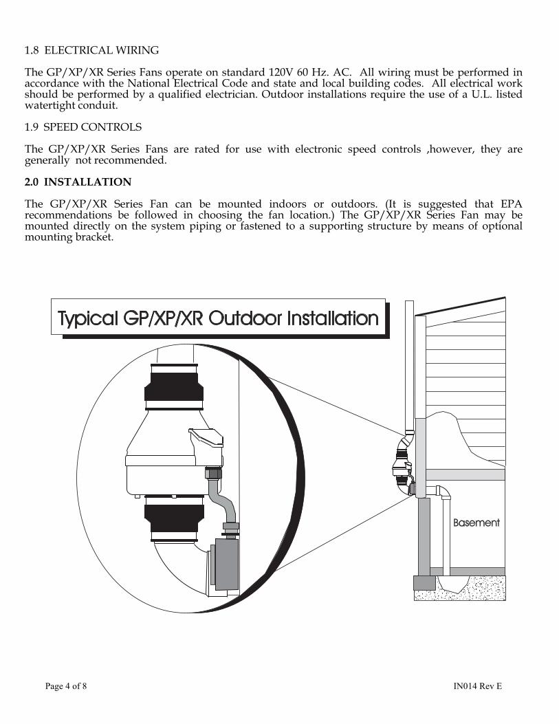
2.0 INSTALLATION
The GP/XP/XR Series Fan can be mounted indoors or outdoors. (It is suggested that EPArecommendations be followed in choosing the fan location.) The GP/XP/XR Series Fan may bemounted directly on the system piping or fastened to a supporting structure by means of optionalmounting bracket.

Page 5 of 8 IN014 Rev E
2.1 MOUNTING
Mount the GP/XP/XR Series Fan vertically withoutlet up. Insure the unit is plumb and level.When mounting directly on the system pipingassure that the fan does not contact any buildingsurface to avoid vibration noise.
2.2 MOUNTING BRACKET (optional)
The GP/XP/XR Series fan may be optionallysecured with the integral mounting bracket on theGP Series fan or with RadonAway P/N 25007-2mounting bracket for an XP/XR Series fan. Foamor rubber grommets may also be used between thebracket and mounting surface for vibrationisolation.
2.3 SYSTEM PIPING
Complete piping run, using flexible couplings asmeans of disconnect for servicing the unit andvibration isolation.
2.4 ELECTRICAL CONNECTION
Connect wiring with wire nuts provided,observing proper connections:
Fan Wire Connection Green Ground Black AC Hot White AC Common
2.5 VENT MUFFLER (optional)
Install the muffler assembly in the selected location in the outlet ducting. Solvent weld allconnections. The muffler is normally installed at the end of the vent pipe.
2.6 OPERATION CHECKS
_____ Verify all connections are tight and leak-free.
_____ Insure the GP/XP/XR Series Fan and all ducting is secure and vibration-free.
_____ Verify system vacuum pressure with manometer. Insure vacuum pressure is less thanmaximum recommended operating pressure
(Based on sea-level operation, at higher altitudes reduce by about 4% per 1000 Feet.) (Further reduce Maximum Operating Pressure by 10% for High Temperature environments) See Product Specifications. If this is exceeded, increase the number of suction points.
_____ Verify Radon levels by testing to EPA protocol.

Page 6 of 8 IN014 Rev E
XP/XR SERIES PRODUCT SPECIFICATIONS
The following chart shows fan performance for the XP & XR Series Fan:
Typical CFM Vs Static Suction "WC 0" .25" .5" .75" 1.0" 1.25" 1.5" 1.75" 2.0"
XP101 125 118 90 56 5 - - - - XP151 180 162 140 117 78 46 10 - - XP201 150 130 110 93 74 57 38 20 - XR161 215 175 145 105 75 45 15 - - XR261 250 215 185 150 115 80 50 20 -
Maximum Recommended Operating Pressure* XP101 0.9" W.C. (Sea Level Operation)** XP151 1.3" W.C. (Sea Level Operation)** XP201 1.7" W.C. (Sea Level Operation)** XR161 1.3" W.C. (Sea Level Operation)** XR261 1.6" W.C. (Sea Level Operation)**
*Reduce by 10% for High Temperature Operation **Reduce by 4% per 1000 feet of altitude
Power Consumption @ 120 VAC XP101 40 - 49 watts XP151 45 - 60 watts XP201 45 - 66 watts XR161 48 - 75 watts XR261 65 - 105 watts
XP Series Inlet/Outlet: 4.5" OD (4.0" PVC Sched 40 size compatible)XR Series Inlet/Outlet: 5.875" ODMounting: Mount on the duct pipe or with optional mounting bracket.Recommended ducting: 3" or 4" Schedule 20/40 PVC PipeStorage temperature range: 32 - 100 degrees F.Normal operating temperature range: -20 - 120 degrees F.Maximum inlet air temperature: 80 degrees F.Size: 9.5H" x 8.5" Dia. Weight: 6 lbs. (XR261 - 7 lbs)Continuous Duty Thermally protectedClass B Insulation 3000 RPMResidential Use Only Rated for Indoor or Outdoor use
Page 7 of 8 IN014 Rev E
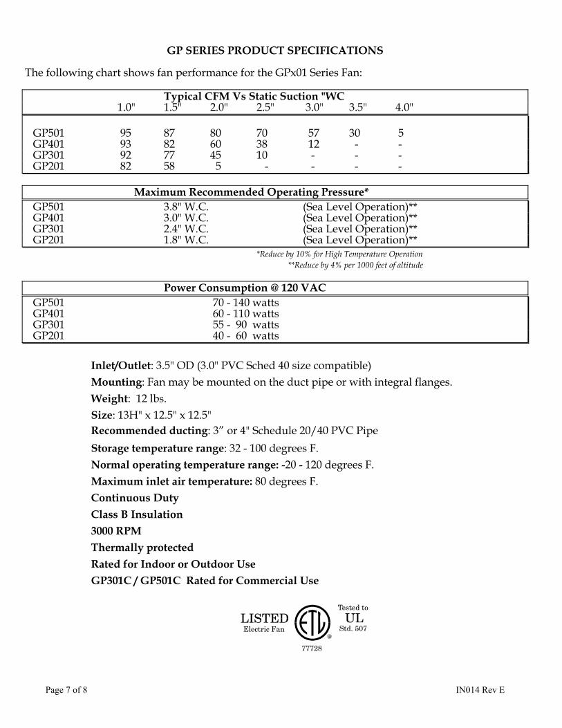
GP SERIES PRODUCT SPECIFICATIONS
The following chart shows fan performance for the GPx01 Series Fan:
Typical CFM Vs Static Suction "WC 1.0" 1.5" 2.0" 2.5" 3.0" 3.5" 4.0"
GP501 95 87 80 70 57 30 5 GP401 93 82 60 38 12 - - GP301 92 77 45 10 - - - GP201 82 58 5 - - - -
Maximum Recommended Operating Pressure* GP501 3.8" W.C. (Sea Level Operation)** GP401 3.0" W.C. (Sea Level Operation)** GP301 2.4" W.C. (Sea Level Operation)** GP201 1.8" W.C. (Sea Level Operation)**
*Reduce by 10% for High Temperature Operation **Reduce by 4% per 1000 feet of altitude
Power Consumption @ 120 VAC GP501 70 - 140 watts GP401 60 - 110 watts GP301 55 - 90 watts GP201 40 - 60 watts
Inlet/Outlet: 3.5" OD (3.0" PVC Sched 40 size compatible)Mounting: Fan may be mounted on the duct pipe or with integral flanges.Weight: 12 lbs.Size: 13H" x 12.5" x 12.5"Recommended ducting: 3” or 4" Schedule 20/40 PVC PipeStorage temperature range: 32 - 100 degrees F.Normal operating temperature range: -20 - 120 degrees F.Maximum inlet air temperature: 80 degrees F.Continuous DutyClass B Insulation3000 RPMThermally protectedRated for Indoor or Outdoor UseGP301C / GP501C Rated for Commercial Use

Page 8 of 8 IN014 Rev E
IMPORTANT INSTRUCTIONS TO INSTALLER
Inspect the GPx01/XP/XR Series Fan for shipping damage within 15 days of receipt. Notify RadonAway of any damagesimmediately. Radonaway is not responsible for damages incurred during shipping. However, for your benefit,Radonaway does insure shipments.
There are no user serviceable parts inside the fan. Do not attempt to open. Return unit to factory for service.
Install the GPx01/XP/XR Series Fan in accordance with all EPA standard practices, and state and local building codesand state regulations.
WARRANTY
Subject to any applicable consumer protection legislation, RadonAway warrants that the GPX01/XP/XR/RP Series Fan (the “Fan”) will be free fromdefects in materials and workmanship for a period of 90 days from the date of purchase (the “Warranty Term”).
RadonAway will replace any Fan which fails due to defects in materials or workmanship. The Fan must be returned (at Owner’s cost) to theRadonAway factory. Any Fan returned to the factory will be discarded unless the Owner provides specific instructions along with the Fan when it isreturned regardless of whether or not the Fan is actually replaced under this warranty. Proof of purchase must be supplied upon request forservice under this Warranty.
This Warranty is contingent on installation of the Fan in accordance with the instructions provided. This Warranty does not apply where anyrepairs or alterations have been made or attempted by others, or if the unit has been abused or misused. Warranty does not cover damage inshipment unless the damage is due to the negligence of RadonAway.
5 YEAR EXTENDED WARRANTY WITH PROFESSIONAL INSTALLATION.
RadonAway will extend the Warranty Term of the fan to 5 years from date of manufacture if the Fan is installed in a professionally designed andprofessionally installed radon system or installed as a replacement fan in a professionally designed and professionally installed radon system.Proof of purchase and/or proof of professional installation may be required for service under this warranty. Outside the Continental United Statesand Canada the extended Warranty Term is limited to one (1) year from the date of manufacture.
RadonAway is not responsible for installation, removal or delivery costs associated with this Warranty.
EXCEPT AS STATED ABOVE, THE GPx01/XP/XR/RP SERIES FANS ARE PROVIDED WITHOUTWARRANTY OF ANY KIND, EITHER EXPRESS OR IMPLIED, INCLUDING, WITHOUT LIMITATION,IMPLIED WARRANTIES OF MERCHANTABILITY AND FITNESS FOR A PARTICULAR PURPOSE.
IN NO EVENT SHALL RADONAWAY BE LIABLE FOR ANY DIRECT, INDIRECT, SPECIAL, INCIDENTAL,OR CONSEQUENTIAL DAMAGES ARISING OUT OF, OR RELATING TO, THE FAN OR THEPERFORMANCE THEREOF. RADONAWAY’S AGGREGATE LIABILITY HEREUNDER SHALL NOT INANY EVENT EXCEED THE AMOUNT OF THE PURCHASE PRICE OF SAID PRODUCT. THE SOLE ANDEXCLUSIVE REMEDY UNDER THIS WARRANTY SHALL BE THE REPAIR OR REPLACEMENT OF THEPRODUCT, TO THE EXTENT THE SAME DOES NOT MEET WITH RADONAWAY’S WARRANTY ASPROVIDED ABOVE.
For service under this Warranty, contact RadonAway for a Return Material Authorization (RMA) number and shippinginformation. No returns can be accepted without an RMA. If factory return is required, the customer assumes all shippingcost to and from factory.
RadonAway3 Saber Way
Ward Hill, MA 01835TEL. (978) 521-3703FAX (978) 521-3964
Record the following information for your records:
Serial No. Purchase Date

Page 1 of 8 IN007 Rev E

Page 2 of 8 IN007 Rev E
RadonAway Ward Hill, MA.
HS Series Fan Installation Instructions
Please Read and Save These Instructions.DO NOT CONNECT POWER SUPPLY UNTIL FAN IS COMPLETELY
INSTALLED. MAKE SURE ELECTRICAL SERVICE TO FAN ISLOCKED IN "OFF" POSITION. DISCONNECT POWER BEFORE
SERVICING FAN.
1. WARNING! Do not use fan in hazardous environments where fan electricalsystem could provide ignition to combustible or flammable materials.
2. WARNING! Do not use fan to pump explosive or corrosive gases.
3. WARNING! Check voltage at the fan to insure it corresponds with nameplate.
4. WARNING! Normal operation of this device may affect the combustion airflowneeded for safe operation of fuel burning equipment. Check for possible backdraftconditions on all combustion devices after installation.
5. NOTICE! There are no user serviceable parts located inside the fan unit.Do NOT attempt to open. Return unit to the factory for service.
6. All wiring must be in accordance with local and national electrical codes.
7. WARNING! In the event that the fan is immersed in water, return unit to factory forservice before operating.
8. WARNING! Do not twist or torque fan inlet or outlet piping as Leakage may result.

Page 3 of 8 IN007 Rev E
INSTALLATION INSTRUCTIONS (Rev D)for DynaVac High Suction Series HS2000 p/n 23004-1 HS3000 p/n 23004-2 HS5000 p/n 23004-3
1.0 SYSTEM DESIGN CONSIDERATIONS
1.1 INTRODUCTION
The DynaVac is intended for use by trained, professional Radon mitigators.The purpose of this instruction is to provide additional guidance for themost effective use of the DynaVac. This instruction should be considered asa supplement to EPA standard practices, state and local building codes andstate regulations. In the event of a conflict, those codes, practices andregulations take precedence over this instruction.
1.2 ENVIRONMENTALS
The DynaVac is designed to perform year-round in all but the harshestclimates without additional concern for temperature or weather. Forinstallations in an area of severe cold weather, please contact RadonAway forassistance. When not in operation, the DynaVac should be stored in an areawhere the temperature is never less than 32 degrees F. or more than 100degrees F. The DynaVac is thermally protected such that it will shut offwhen the internal temperature is above 104 degrees F. Thus if the DynaVac isidle in an area where the ambient temperature exceeds this shut off, it willnot restart until the internal temperature falls below 104 degrees F.
1.3 ACOUSTICS
The DynaVac, when installed properly, operates with little or no noticablenoise to the building occupants. There are, however, some considerations tobe taken into account in the system design and installation. When installingthe DynaVac above sleeping areas, select a location for mounting which is asfar away as possible from those areas. Avoid mounting near doors, fold-downstairs or other uninsulated structures which may transmit sound. Insure asolid mounting for the DynaVac to avoid structure-borne vibration or noise.
The velocity of the outgoing air must also be considered in the overallsystem design. With small diameter piping, the "rushing" sound of the outletair can be disturbing. The system design should incorporate a means to slowand quiet the outlet air. The use of the RadonAway Exhaust Muffler, p/n24001, is strongly recommended.

Page 4 of 8 IN007 Rev E
1.4 GROUND WATER
Under no circumstances should water be allowed to be drawn into the inlet ofthe DynaVac as this may result in damage to the unit. The DynaVac should bemounted at least 5 feet above the slab penetration to minimize the risk offilling the DynaVac with water in installations with occasional high watertables.
In the event that a temporary high water table results in water at or aboveslab level, water will be drawn into the riser pipes thus blocking air flowto the DynaVac. The lack of cooling air will result in the DynaVac cyclingon and off as the internal temperature rises above the thermal cutoff andfalls upon shutoff. Should this condition arise, it is recommended that theDynaVac be disconnected until the water recedes allowing for return to normaloperation.
1.5 CONDENSATION & DRAINAGE
(WARNING!: Failure to provide adequate drainage for condensation can resultin system failure and damage the DynaVac).
Condensation is formed in the piping of a mitigation system when the air inthe piping is chilled below its dew point. This can occur at points wherethe system piping goes through unheated space such as an attic, garage oroutside. The system design must provide a means for water to drain back to aslab hole to remove the condensation.
The use of small diameter piping in a system increases the speed at which theair moves. The speed of the air can pull water uphill and at sufficientvelocity it can actually move water vertically up the side walls of the pipe.This has the potential of creating a problem in the negative pressure (inlet)side piping. For DynaVac inlet piping, the following table provides theminimum recommended pipe diameters as well as minimum pitch under severalsystem condition. Use this chart to size piping for a system.
PipeDiam.
Minimum Rise per Foot of Run*
@ 25 CFM @ 50 CFM @ 100 CFM4" 1/32 " 3/32 " 3/8 "3" 1/8 " 3/8 " 1 1/2 "
*Typical operational flow rates:
HS3000, or HS5000 20 - 40 CFMHS2000 50 - 90 CFM
All exhaust piping should be 2" PVC.
Run
Rise

Page 5 of 8 IN007 Rev E
1.6 "SYSTEM ON" INDICATOR
A properly designed system should incorporate a "System On" Indicator foraffirmation of system operation. A Magnehelic pressure gauge is recommendedfor this purpose. The indicator should be mounted at least 5 feet above theslab penetration to minimize the risk of filling the gauge with water ininstallations with occasional high water tables.
1.7 SLAB COVERAGE
The DynaVac can provide coverage of well over 1000 sq. ft. per slabpenetration. This will, of course, depend on the sub-slab aggregate in anyparticular installation and the diagnostic results. In general, sand andgravel are much looser aggregates than dirt and clay. Additional suctionpoints can be added as required. It is recommended that a small pit (2 to 10gallons in size) be created below the slab at each suction hole.
1.8 ELECTRICAL WIRING
The DynaVac plugs into a standard 120V outlet. All wiring must be performedin accordance with the National Electrical Code and state and local buildingcodes.
1.8a ELECTRICAL BOX (optional)
The optional Electrical Box (p/n 20003) provides a weathertight box withswitch for outdoor hardwire connection. All wiring must be performed inaccordance with the National Electrical Code and state and local buildingcodes. All electrical work should be performed by a qualified electrician.Outdoor installations require the use of a U.L. listed watertight conduit.
1.9 SPEED CONTROLS
Electronic speed controls can NOT be used on HS series units.

Page 6 of 8 IN007 Rev E
2.0 INSTALLATION
2.1 MOUNTING
Mount the DynaVac to the wall studs, or similar structure, in the selectedlocation with (4) 1/4" x 1 1/2" lag screws (not provided). Insure theDynaVac is both plumb and level.
2.2 DUCTING CONNECTIONS
Make final ducting connection to DynaVac with flexible couplings. Insure allconnections are tight. Do not twist or torque inlet and outlet piping onDynaVac or leaks may result.
2.3 VENT MUFFLER INSTALLATION
Install the muffler assembly in the selected location in the outlet ducting.Solvent weld all connections. The muffler is normally installed above theroofline at the end of the vent pipe.
2.5 OPERATION CHECKS
____ Make final operation checks by verifying all connections are tight andleak-free.
____ Insure the DynaVac and all ducting is secure and vibration-free.
____ Verify system vacuum pressure with Magnehelic. Insure vacuum pressureis less than the maximum recommended as shown below:
DynaVac HS2000 14" WCDynaVac HS3000 21" WCDynaVac HS5000 40" WC
(Above are based on sea-level operation, at higher altitudes reduce above byabout 4% per 1000 Feet.)If these are exceeded, increase number of suction points.
____ Verify Radon levels by testing to EPA protocol.

Page 7 of 8 IN007 Rev E
Addendum
PRODUCT SPECIFICATIONS
*Power consumption varies with actual load conditions
Inlet: 3.0" PVCOutlet: 2.0" PVCMounting: Brackets for vertical mountWeight: Approximately 18 lbs.Size: Approximately 15"W x 13"H x 8"DMinimum recommended inlet ducting (greater diameter may always be used ):HS3000, HS5000 --- 2.0" PVC PipeHS2000 --- Main feeder line of 3.0" or greater PVC Pipe
Branch lines (if 3 or more) may be 2.0" PVC PipeOutlet ducting: 2.0" PVCStorage temperature range: 32 - 100 degrees F.Thermally protectedLocked rotor protectionInternal Condensate Bypass

Page 8 of 8
IMPORTANT INSTRUCTIONS TO INSTALLER
Inspect the HS Series Fan for shipping damage within 15 days of receipt. NotifyRadonAway of any damages immediately. Radonaway is not responsible for damagesincurred during shipping. However, for your benefit, Radonaway does insureshipments.
There are no user serviceable parts inside the fan. Do not attempt to open. Return unitto factory for service.
Install the HS Series Fan in accordance with all EPA standard practices, and state andlocal building codes and state regulations.
Subject to any applicable consumer protection legiswill be free from defects in materials and workmans“Warranty Term”). Outside the Continental United date of manufacture.
RadonAway will replace any Fan which fails due to(at owner’s cost) to the RadonAway factory. Proof Warranty.
This Warranty is contingent on installation of the Fadoes not apply where any repairs or alterations havabused or misused. Warranty does not include damRadonAway.
RadonAway is not responsible for installation, remo
EXCEPT AS STATED ABOVE, THE HS SEOF ANY KIND, EITHER EXPRESS OR IMPWARRANTIES OF MERCHANTABILITY A
IN NO EVENT SHALL RADONAWAY BE LINCIDENTAL, OR CONSEQUENTIAL DAMOR THE PERFORMANCE THEREOF. RADSHALL NOT IN ANY EVENT EXCEED THEPRODUCT. THE SOLE AND EXCLUSIVE REPAIR OR REPLACEMENT OF THE PROWITH RADONAWAY’S WARRANTY AS PR
For service under this Warranty, contact RadonAshipping information. No returns can be accepteassumes all shipping cost to and from factory.
Ra3 S
Ward HTEL. (9FAX (9
Record the following information for your recor
Serial No. Purchase Date
WARRANTY
lation, RadonAway warrants that the HS Series Fan (the “Fan”)hip for a period of one (1) year from the date of manufacture (the
States and Canada the Warranty Term is one (1) year from the
defects in materials or workmanship. The Fan must be returnedof purchase must be supplied upon request for service under this
n in accordance with the instructions provided. This Warrantye been made or attempted by others, or if the unit has beenage in shipment unless the damage is due to the negligence of
val or delivery costs associated with this Warranty.
RIES FANS ARE PROVIDED WITHOUT WARRANTYLIED, INCLUDING, WITHOUT LIMITATION, IMPLIEDND FITNESS FOR A PARTICULAR PURPOSE.
IABLE FOR ANY DIRECT, INDIRECT, SPECIAL,AGES ARISING OUT OF, OR RELATING TO, THE FANONAWAY’S AGGREGATE LIABILITY HEREUNDER AMOUNT OF THE PURCHASE PRICE OF SAIDREMEDY UNDER THIS WARRANTY SHALL BE THEDUCT, TO THE EXTENT THE SAME DOES NOT MEETOVIDED ABOVE.
way for a Return Material Authorization (RMA) number andd without an RMA. If factory return is required, the customer
donAwayaber Wayill, MA 0183578) 521-370378) 521-3964
ds:
IN007 Rev E

Performance Curve, GP501.
0
0.5
1
1.5
2
2.5
3
3.5
4
4.5
0 10 20 30 40 50 60 70 80 90 100
Air Flow, CFM
Stat
ic P
ress
ure,
In W
CBy: TSDate:10/14/05

Performance Curve, HS2000
0
2
4
6
8
10
12
14
16
18
20
0 20 40 60 80 100 120
Air Flow, CFM
Stat
ic P
ress
ure,
In W
C
0
40
80
120
160
200
240
280
320
360
400
Pow
er, W
atts
Static Pressure, IN WCPower, Watts
By: TSDate:4/16/07

Performance Curve, HS3000
0
5
10
15
20
25
30
0 5 10 15 20 25 30 35 40 45
Air Flow, CFM
Stat
ic P
ress
ure,
In W
C
0
40
80
120
160
200
240
280
320
360
400
Pow
er, W
atts
Static Pressure, IN WCPower, Watts
By: TSDate:4/16/07

Performance Curve, HS5000
0
10
20
30
40
50
60
0 10 20 30 40 50 60
Air Flow, CFM
Stat
ic P
ress
ure,
In W
C
0
40
80
120
160
200
240
280
320
360
400
Pow
er, W
atts
Static Pressure, IN WCPower, Watts
By: TSDate:4/16/07

Radon Mitigation FansSpecially designed for radon mitigation, GPSeries Fans provide a wide range ofperformance that makes them ideal for mostsubslab radon mitigation systems.
ss 5-Year Warranty
ss Mounts on duct pipe or with integral flange
ss 3" diameter ducts for use with 3" or 4" pipe
ss Electrical box for hard wire or plug in
ss ETL Listed - for indoor or outdoor use.
Choice of model is dependent on certain building characteristics including sub-slab materials and should be made by a radon professional.
The following chart shows performance of GP Series fans:
FOR FURTHER INFORMATION CONTACT:
Model WattsMaximumPressure
"WC
Typical CFM vs. Static Pressure WC1.0" 1.5" 2.0" 2.5" 3.0" 3.5" 4.0"
GP201
GP301GP401GP501
40-60
55-90
60-11070-140
2.0
2.63.44.2
82
92
9395
58778287
5456080
-10
4070
--
1557
-
--
30
-
--
10
0902P/N 02002
A
B
DimensionsModel A B C
Duct Size
3''13''GP series 12.5''
C
C
GP Series
