operation and maintenance model 89299 - gmptools.com
TRANSCRIPT

Page 1
Operation and Maintenance Model 89299
All rights reserved. No part of this publication may be copied, reproduced or transmitted in any form whatso-ever without the written permission of General Machine Products Co., Inc.
General Machine Products Co., Inc. • 3111 Old Lincoln Hwy • Trevose, PA 19053 • USA
TEL: +1-215-357-5500 • FAX: +1-215-357-6216 • EMAIL: [email protected]
CABLE BLOWING MACHINE
Manual P/N 33709 Rev 6 040616 AKK
PNEUMATIC

Page 2
REVISION HISTORY:
Rev.no Date Details Author
01 Jul -27-10 Original issue A. Sibun
02 AUG-26-14 Reformat for US A. Konschak
03 April 8 15 Updated air supply quality A. Konschak
04 Jan 13 2016 Update Oiler adjustment and Oiler fill
Removed service details Added 8.5mm
A Konschak
05 March 22 2016 Updated various photos A Konschak
06 April 5 2016 Added oil drip notification A Konschak

Page 3
CONTENTS
1. Safety Instructions
2. Critical Points that dramatically affect the operation of the machine
3. General Description
4. Specification
5. Operating procedures
6. Maintenance
7. Procedure for changing inserts in the microduct clamp
8. Procedure for changing inserts in the air box
9. Procedure for changing inserts in the infeed and exit guides
10. Procedure for replacing the air box housing seal
11. Procedure for changing the air box infeed guide
12. Procedure for changing the cable drive belts
13. Procedure for tensioning the drive belts
14. Procedure for checking and replacing the air motor drive belt
15. Tensioning of the air motor drive belt
16. Procedure for checking/refilling the oil level of the air lubricator
17. Monthly Service – check list
18. Service History Record
19. Microduct integrity and Lubrication
20. Recommended Spares List
21. Troubleshooting APPENDICES Appendix 1 Cable and microduct insert selection chart Appendix 2 Recommended torque control potentiometer settings Appendix 3 Counter/Rate meter Programming Instructions

Page 4
1.0 SAFETY INSTRUCTIONS THIS EQUIPMENT SHOULD BE USED ONLY BY PERSONNEL WHO HAVE BEEN GIVEN THE APPROPRIATE TRAINING, AND WHO ARE COMPETENT TO USE IT. THESE INSTRUCTIONS ARE TO BE MADE AVAILABLE TO OPERATORS OF THIS EQUIPMENT AT ALL TIMES, FAILURE TO OBSERVE THESE SAFETY INSTRUCTIONS COULD RESULT IN SERIOUS PERSONAL INJURY AND/OR PROPERTY DAMAGE. WORK AREA AND GENERAL SAFETY 1. Read and understand the operation and maintenance manual supplied with this equipment. Keep it in a
convenient place for future reference. 2. Keep children and untrained personnel away from this equipment while in operation. 3. Keep all guards and safety devices in place. Do not operate this equipment with guards removed or dam-
aged. 4. Keep hands, feet and loose clothing away from moving parts, especially at cable entry points. 5. Always stop the machine and isolate compressed air and electrical services to carry out lubrication and ser-
vicing. 6. Check machine before starting for worn or damaged parts. Check for signs of loose nuts and bolts etc. 7. If machine is left unattended, ensure that unauthorized use is prevented. 8. Never leave the machine unattended while in use. 9. Consider the use of safety barriers, especially when used in public places, observe all statutory require-
ments for working environments. 10. Beware of pinch points involved with rotating components, 11. Beware of hot surfaces, machine uses compressed air. 12. When operating machine always wear appropriate safety clothing, ear defenders, eye protection, hard hat,
safety shoes and leather gloves, machine operates with compressed air at up to 15 Bar. 13. Prior to installation ensure the microduct route is connected properly. 14. Beware of exposed electrical contacts. Do not touch, or allow metal objects to come into contact. 15. Machine may cause additional fire hazard if involved in an existing fire due to compressed air. 16. No personnel are to be in manholes or ducts when the Cable Blowing Machine is being operated. 17. The machine must be operated on firm ground. 18. Stay clear of cables or lines under tension. 19. Stay clear of pressurized air line and microduct. 20. Only use the machine for its intended purpose, do not use the roller drive without the air chamber to push
or to retrieve cable, blow air in the far end to help cable recovery. 21. Do not place cable drum too close to the Cable Blowing Machine. 22. The compressed air supply must not be allowed to enter the air chamber or microduct before the rollers
have been closed on to the cable. Do not turn the air on until a reasonable length of cable 150 ft. (50m) has been installed into the microduct.
23. Ensure the cable drum rotates freely on its stand, the cable should leave from the top of the drum. 24. The cable should enter the machine in a clean and dry condition. In damp, dusty atmospheres, the cable
should be cleaned continuously as it enters the machine. FAILURE TO DO SO MAY RESULT IN PERSONAL INJURY, AS THE CABLE COULD BE EJECTED FROM THE CABLE BLOWING MACHINE WITH HIGH FORCE AND VELOCITY.

Page 5
GENERAL PNEUMATIC SAFETY INSTRUCTIONS The GMP Fiber Optic Cable Blowing Machine is a pneumatic device, using pressurized air to project cable
at high velocities. Please observe the following precautions when operating the Cable Blowing Machine:
Compressed air can cause flying debris. This could cause personal injury. Always wear personal protec-tive equipment.
Ensure no personnel are in the manhole at the far end of the cable run. Severe personal injury may re-sult.
Never open the air chamber when pressurized.
Ensure the ball valve and flow control valve are fully closed before connecting the air supply to the motor system. Unwanted operation and personal injury may otherwise result.
Only authorized, fully trained personnel should operate the air compressor. GENERAL ELECTRICAL SAFETY INSTRUCTIONS The machine has electronic and electrical power and control circuits. Electric shock hazards exist that could result in severe personal injury. Observe the following precautions to avoid electrical hazards: Do not operate in water. Do not expose the machine to rain.
Do not remove cover of electronic control panel or power supply unit. There are no user serviceable parts
inside. Refer servicing to qualified service personnel.
Page 6
2.0 CRITICAL POINTS THAT DRAMATICALLY AFFECT THE OPERATION OF THE CABLE BLOWING MACHINE PRESSURE ON THE CABLE (POSITION OF THE CLOSE ARM ASSEMBLY) SHOULD BE SET AS PER
THE INSTRUCTIONS.
BELTS TO BE CLOSED AT ALL TIMES WHEN CABLE IS INSTALLED INTO MACHINE.
CORD SEALS IN AIR CHAMBER IN GOOD CONDITION AND CORRECTLY FITTED TO PROVIDE GOOD SEALING.
CORRECT CABLE SEAL FITTED.
MICRODUCT FULLY CONNECTED AND PRESSURE-TESTED.
MICRODUCT AND CONNECTING FITTINGS ARE SUITABLE FOR OPERATING AT 15 BAR AIR PRESSURE.
MICRODUCT CLAMP SECURELY TIGHTENED.
COMPRESSOR CAPACITY >1.5m3/min @ 15 BAR CONTAINING NO MORE THAN 7.732 G/M^3 RE-SIDUAL WATER CONTENT WITH A PRESSURE DEW POINT OF +3 DEG C AS PER DIN ISO 8573-1 CLASS 4.
CABLE DRUM MUST BE LOCATED DIRECTLY BEHIND AND IN LINE WITH THE BLOWING MA-CHINE.
AIR CHAMBER, DRIVE BELTS AND PULLEYS, CABLE GUIDES, MUST BE CLEAN AND FREE FROM DEBRIS, SLUDGE, DIRT, WATER AND LUBRICANT.
THE CABLE MUST BE HAND GUIDED INTO THE BLOWING MACHINE THROUGH A DRY CLEAN CLOTH BY THE OPERATOR WEARING WORK GLOVES.
ENSURE THE COMPRESSED AIR SUPPLY IS NOT APPLIED TO THE CABLE UNTIL APPROXIMATE-LY 50 METERS OF CABLE HAVE BEEN INSTALLED OR THE MOTOR BEGINS TO LABOR.

Page 7
DISCLAIMER General Machine Products Co., Inc. takes care in the design of its products to insure that the cable is protected during installation. Due to the variety and different methods of cable manufacture the responsibility of checking the cable compatibility with the equipment lies with the operator. Therefore, General Machine Products cannot accept liability for any damage to the cable.

Page 8
3.0 GENERAL DESCRIPTION The GMP Pneumatic AirStream machine is designed to install small diameter cable into underground microduct. The machine uses an air motor to drive a pair of compliant belts (both belts are driven). The belts are covered with a compliant coating to prevent damage to the cable. A range of different coatings and profiles are available depending on the surface texture of the cable being installed. The belts offer a large surface area in contact with the cable ensuring high grip with reduced compressive loading. During installation, the torque applied to the cable by the rollers can be adjusted to prevent the cable buckling and to prevent damage to the cable. A full range of accessories is available to allow the machine to handle a wide range of cables and microduct. This machine has been designed to be extra robust, reliable and simple to operate by having only one power source. This means there is no need to have a generator on site, only a compressor is required. The machine may be placed on the ground or on a support to bring the cable to a suitable height. A separate reinforced transit housing is provided, this will protect the machine from damage during transit and can be used as a support for the machine when being used to install cable.
4.0 SPECIFICATION
Cable size: 0.098" to 0.433" ø2.5 to ø11.0 Microduct size: (OD) 0.197" to 0.709" ø5 to ø18.0 Cable speed: 0-262 ft/min 0-80 m/min. Maximum pushing force: 48.5 lb. 22 Kg. Maximum air pressure: 210 psi. 15 bar.
Recommended Compressor1 >1.5 m3/min @ 15 bar
Weight approx. 31 lbs. 14 Kg Weight inc case approx. 68 lbs. 31 Kg Dimensions (ht x length x width) 9 1/2" x 18 1/8" x 12 3/4" 240 mm x 460 mm x 325 mm Case Dimensions (ht x length x width) 16 1/2" x 16" x 201/2" 419 mm x 521 mm x 406 mm
1 The compressed air supply is to contain no more than 7.732 g/m^3 residual water content with a pressure dew point of +3 deg C as per DIN ISO 8573-1 Class 4.

Page 9
Cable Drum AirStream Machine
Microduct Route
5.0 OPERATING PROCEDURE IT IS IMPERATIVE THAT ALL PERSONS USING, OPERATING OR MAINTAINING THIS CABLE BLOWING MACHINE: HAVE RECEIVED COMPREHENSIVE TRAINING IN THE USE OF THIS MACHINE. ARE COMPETENT TO USE IT, AUTHORIZED TO USE IT AND HAVE READ AND UNDERSTOOD THIS MANUAL. GENERAL MACHINE PRODUCTS CO., INC. CANNOT BE HELD RESPONSIBLE FOR
MISUSE OF THIS EQUIPMENT. Set up for installing cable with the machine mounted above ground: Position the machine in line with the route of the duct. Position the cable drum behind the machine and in line with the machine. See sketch below (this shows a plan view of the recommended set up). Ensure the machine is secure (either on its own stand or a separate suitable stand). Ensure the machine is fitted with the appropriate guides and collets to suit the cable being installed and mi-croducts into which the cable is to be installed. (See Appendix 1 for details of interchangeable parts). To set the machine up to install cable it will be necessary to: Select the appropriate torque setting for the cable being installed, if in doubt start with the low torque set-
ting. Fit the microduct into which the cable is to be installed into the air box and microduct clamp. Fit the cable through the machine. Connect the air supply to the machine. Connect the electrical power input to the machine. Turn on the counter system.

Page 10
Fit the microduct into which the cable is to be installed into the air box and mi-croduct clamp. It is recommended that a length of microduct similar in size to the microduct into which the cable is to be in-stalled be fitted in the microduct clamp. This length of microduct may then be connected to the installed mi-croduct (the length of microduct under-ground into which the cable is to be in-stalled) using a suitable connector. Slide a suitable size O ring over the end of the microduct. Fit the microduct into the end of the air box housing so that it protrudes approx. half way into the housing, position the O ring so that it sits against the seal face, as shown in the illustration opposite.
Once the microduct has been posi-tioned, the microduct clamp may be closed, the swing bolt swung down and the thumb nut tightened, the microduct is now secure.

Page 11
Fit the cable through the machine. It is now possible to insert the cable in the machine, this can be carried out in 2 ways. Method 1: This method is only suitable if the machine has been previously set up with the correct infeed and exit guides from the belts to suit the cable being installed, see section 9 for the procedure for changing the guides. Fully close the flow control valve. Set a pressure of roughly 2 bar. Move the close assembly arm fully to the right. Select the appropriate split cable seal (see appendix 1) and position it in the groove in the seal housing. Open the ball valve and slowly turn the flow control valve knob counter clockwise until the belts are just
moving. Take the cable to be installed and pass it through the infeed guide so that the end is between the belts. Move the close arm to the left gently until the cable is gripped (there is no need to apply the full installation
pressure to the cable at this stage) – the cable should now feed slowly through the belts, cable seal, air box and into the microduct.
Close the ball valve and the flow control valve to stop the machine. Close and tighten the thumb nut securing the air box. Prepare the machine to install the cable into the microduct.
Move the close assembly to the far right to fully open the drive
Loosen the thumb nut and open the seal housing

Page 12
Method 2: Move the close assembly arm fully to the right. Remove the top halves of the belt infeed and exit guides using the knurled screws (screwdriver slots are
provided if necessary). Ensure the correct guides are fitted for the cable (see appendix 1) Select the appropriate split cable seal (see appendix 1) and position it round the cable. Take the cable and simultaneously place it into the microduct in the air box and thread it through the
gaps in the belts guards and between the belts. Ensure the cable seal seats in the appropriate groove in the seal housing.
Replace the top halves of the belt infeed and exit guides. Close the air box Prepare the machine to install the cable in the microduct. Setting the clamp force: Close the drive roller assembly onto the cable as follows: The photo shows the drive roller close thumb screw slightly loosened. (The assembly is free to move). This thumb screw is attached to the clamp arm lever. The clamp arm lever controls the position of the roller as-sembly. As the clamp arm is moved around the arc the belts move together and apart. When the clamp arm is furthest to the right, the gap be-tween the belts is at a maximum. And vice versa. When preparing the machine to insert the cable, the clamp arm is positioned at its furthest point to the right (rollers open). Once the cable has been positioned in the machine the rollers must be closed on the cable in order to drive the cable. (And to stop the cable being dragged back out of the machine by any tension in the ca-ble). The amount of pressure on the cable can be varied simply by loosening the thumb nut, moving the clamp arm lever to the right or left; as required, and tightening the thumbscrew. As more experience is gained using the machine, the amount of compression required will become clear. Note: An alternative method of setting the compression force is detailed in the note at the end of Appendix 2.
Close assembly clamp lever arm

Page 13
Connect the air supply to the machine. The air inlet to the machine is made via a jaymac coupling on either the combined air input assembly and/or the jaymac connected to the back of the air box. An on/off valve is fitted to the air box to provide control of the air supply to the operator and a pressure gauge is fitted to indicate air box pressure. Maximum safe working pressure is 15 Bar ( 210 psi). Connect the battery to the counter circuit. The two 9v batteries required to power the counter circuit have a connector each. These connectors are handed and so cannot be connected incorrectly. Using a large coin simply twist through a quarter turn the 4 catches holding the battery box to the control housing to release them and gain access. Place the batteries in the cradle, connect the power leads and then replace the battery box into its slot. Push the 4 catches until they click into place and retain the battery box. The on/off switch on the side of the counter assembly now controls power going to the counter. This should be turned off when not in use to preserve battery life. The counter will remember the previous distance trav-elled the next time it is turned on. Connect the condensate drain Push the provided length of 6mm microduct into the push-in fitting of the condensate drain. Then place the other end of the microduct into a suitable bottle so that any ejected condensate is collected and not released into the environment.
The machine is now ready to start the cable installation.
Airlines are connected as shown

Page 14
Set up for installing cable with the machine mounted below ground: The set up is similar to the set up for installing cable above ground, (described above) typically this type of installation is demanded for “series blowing” i.e. when a length of cable is already installed, and the limit of installation distance is reached. In such cases it is customary to couple a “series machine” sited down a man-hole some distance from the point of main installation. This machine operates in conjunction with the ma-chine sited at the main point of installation. The GMP Pneumatic Airstream machine is ideally suited to this type of operation, it may be coupled with a second machine to increase the distance a single cable can be installed without couplings. The only difference between this set up, and the set up for installing cable with the machine above ground, is that there will be no drum stand carrying the cable drum. The cable will be exit-ing from one side of the manhole and blown into the microduct at the other side of the manhole. The machine should be aligned with both the incoming cable and the outgoing microduct path, both side to side and up and down. NOTE: THE MACHINE MUST NOT BE SUBMERGED IN WATER.
If the hole is full of water it must be pumped out before placing the machine on the bottom of the hole.
Page 15
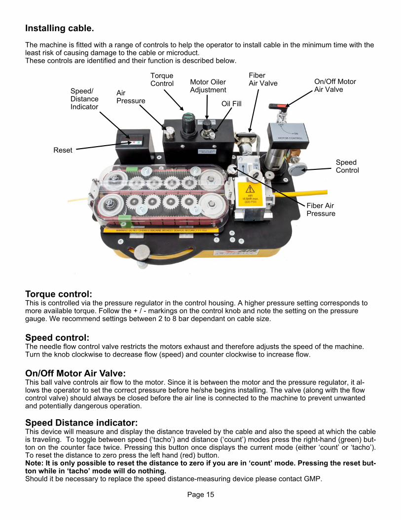
Installing cable. The machine is fitted with a range of controls to help the operator to install cable in the minimum time with the least risk of causing damage to the cable or microduct. These controls are identified and their function is described below. Torque control: This is controlled via the pressure regulator in the control housing. A higher pressure setting corresponds to more available torque. Follow the + / - markings on the control knob and note the setting on the pressure gauge. We recommend settings between 2 to 8 bar dependant on cable size. Speed control: The needle flow control valve restricts the motors exhaust and therefore adjusts the speed of the machine. Turn the knob clockwise to decrease flow (speed) and counter clockwise to increase flow. On/Off Motor Air Valve: This ball valve controls air flow to the motor. Since it is between the motor and the pressure regulator, it al-lows the operator to set the correct pressure before he/she begins installing. The valve (along with the flow control valve) should always be closed before the air line is connected to the machine to prevent unwanted and potentially dangerous operation. Speed Distance indicator: This device will measure and display the distance traveled by the cable and also the speed at which the cable is traveling. To toggle between speed (‘tacho’) and distance (‘count’) modes press the right-hand (green) but-ton on the counter face twice. Pressing this button once displays the current mode (either ‘count’ or ‘tacho’). To reset the distance to zero press the left hand (red) button. Note: It is only possible to reset the distance to zero if you are in ‘count’ mode. Pressing the reset but-ton while in ‘tacho’ mode will do nothing. Should it be necessary to replace the speed distance-measuring device please contact GMP.
Speed/Distance Indicator
Reset
Torque Control On/Off Motor
Air Valve
Speed Control
Fiber Air Valve
Air Pressure
Motor Oiler Adjustment
Oil Fill
Fiber Air Pressure

Page 16
To install cable: For the first time i.e. installing a cable type that has not been installed before and whose characteristics are unknown. Using the supplied airline adaptor, connect the air lines to the machine and the compressor (checking the ball valves and flow control valve on the motor are closed). It is now necessary to set the torque to a position appropriate to the stiffness of the cable and the characteristics of the cable insulation. This is done via the control knob and pressure gauge, if in doubt start at 2 bar. See Appendix 2 for recom-mendations. If the cable type has been installed before, the settings will be available; the torque control pressure may be set at the previously determined position. Open the motor ball valve. Slowly open the flow control valve. The rollers will now start to turn and the cable will feed through the air box (increase speed setting to max. if required). When the cable has travelled a reasonable distance, (say 100 me-ters) turn on the air feed to the air box; this will help the machine to feed the cable. The microduct route, through which the cable is to be fed, should be configured in such a way that the cable can feed all the way along the microduct and out the other end. It will be necessary to be able to determine when the cable has emerged at the other end of the microduct route. A typical way of achieving this aim is to have a colleague positioned at the end of the microduct run; in contact with the main installer using a radio transmitter/receiver of some description. In this way the main installer may be advised when the cable has completed the run, he can then stop the machine. If there is an unexpected obstruction in the microduct route the rollers will see this as an increase in torque demand, assuming the torque control pressure has been set at an appropriate level, the rollers will stop turn-ing before they push the cable so hard as to cause it to buckle. If (due to lack of previous knowledge of the cable characteristics) the torque control pressure has been set at a figure which is too small to push the cable the setting may be increased. Bear in mind that this will increase the risk of the cable being damaged by buckling.
Grounding the Airstream Cable Blower. Certain cable/duct combinations can generate large static build-ups. If this is occurring, ground the Airstream via the ground point on the air box via a suitable copper conductor to a ground at the power source or earth.
Grounding Point
Airlines are connected as shown

Page 17
As a general rule, every time an interchangeable part is removed and replaced by a part of a different size, shape etc. the part being removed should be thoroughly cleaned before being returned to its box. Similarly the cavity from which it was re-moved can also be cleaned prior to the assembly of the replacement part.
Air box parts: keep clean, build up of moisture and dust will prevent the joint faces from mating, prevent the housing seal from sealing etc. Use any traditional workshop cleaning agent.
Microduct clamp inserts: keep clean, build up of moisture and dust, particularly in the grooves, will re-duce the clamping effect. Use tradi-tional workshop cleaning agent.
Cable infeed and exit guides: keep clean, build up of moisture and dust may nip the cable. Use any traditional workshop cleaning agent.
6.0 Maintenance The GMP AirStream Cable Blowing Machine has been designed to give reliable, trouble free service over long periods. The machine requires no sophisticated maintenance procedures, simple common sense checks and precautions are all that are needed. The main source of breakdown and/or malfunction of a machine being used outdoors is contamination by the elements, this contamination may be introduced into the machine in a number of different ways. There may be mud, dust or other contaminants carried into the machine on the cable or microduct (there may be surface coatings of lubricants or other release type agents on the outer surfaces of the cable and mi-croduct, this could build up on the belts and make them slip). The machine may be set down on a muddy surface, or be splashed by road going vehicles when it is being used by the roadside. It is convenient to consider each function of the machine in turn.
Page 18
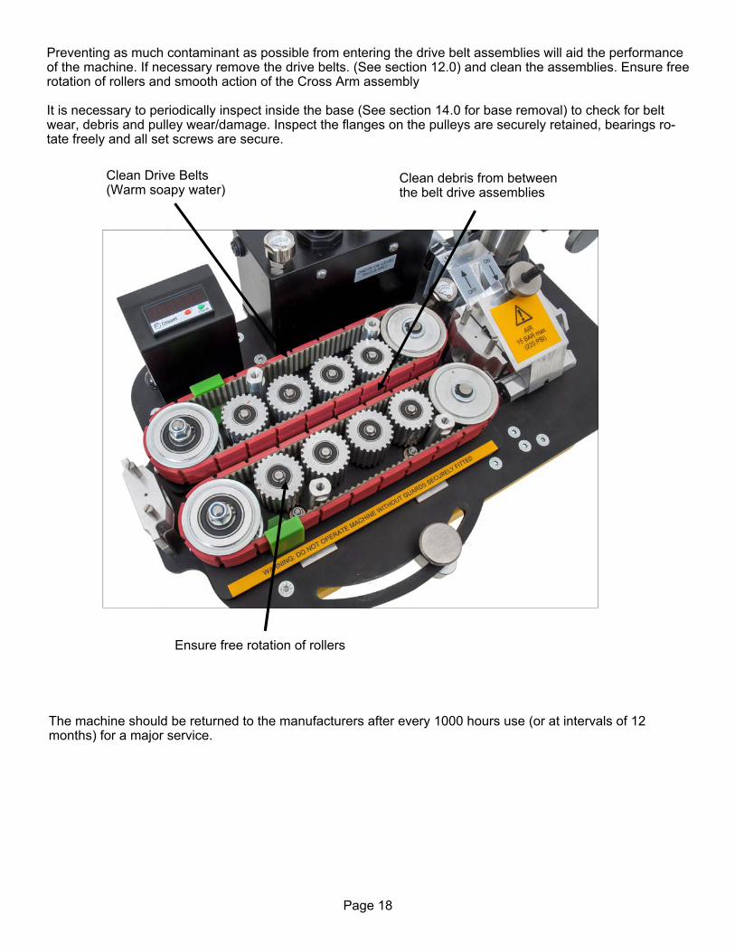
The machine should be returned to the manufacturers after every 1000 hours use (or at intervals of 12 months) for a major service.
Clean Drive Belts (Warm soapy water)
Clean debris from between the belt drive assemblies
Ensure free rotation of rollers
Preventing as much contaminant as possible from entering the drive belt assemblies will aid the performance of the machine. If necessary remove the drive belts. (See section 12.0) and clean the assemblies. Ensure free rotation of rollers and smooth action of the Cross Arm assembly It is necessary to periodically inspect inside the base (See section 14.0 for base removal) to check for belt wear, debris and pulley wear/damage. Inspect the flanges on the pulleys are securely retained, bearings ro-tate freely and all set screws are secure.
Page 19
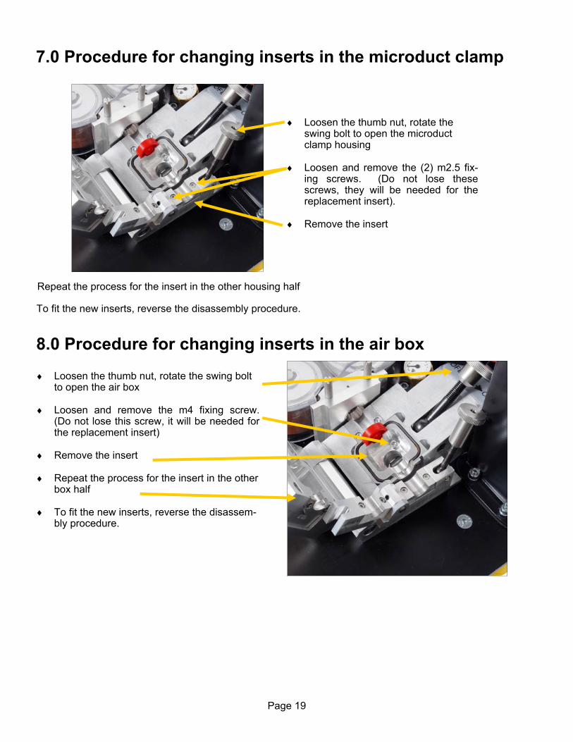
Loosen the thumb nut, rotate the swing bolt to open the microduct clamp housing
Loosen and remove the (2) m2.5 fix-
ing screws. (Do not lose these screws, they will be needed for the replacement insert).
Remove the insert
Loosen the thumb nut, rotate the swing bolt to open the air box
Loosen and remove the m4 fixing screw.
(Do not lose this screw, it will be needed for the replacement insert)
Remove the insert Repeat the process for the insert in the other
box half To fit the new inserts, reverse the disassem-
bly procedure.
7.0 Procedure for changing inserts in the microduct clamp
Repeat the process for the insert in the other housing half
To fit the new inserts, reverse the disassembly procedure.
8.0 Procedure for changing inserts in the air box
Page 20
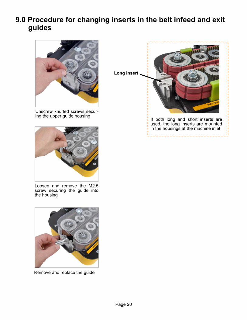
Unscrew knurled screws secur-ing the upper guide housing
Loosen and remove the M2.5 screw securing the guide into the housing
Remove and replace the guide
If both long and short inserts are used, the long inserts are mounted in the housings at the machine inlet
Long Insert
9.0 Procedure for changing inserts in the belt infeed and exit guides

Page 21
Cut a length of 0.08inch seal-ing material 2 1/8” long (a little longer than is necessary).
Apply a thin coat of 3M Rubber and Gasket Adhesive to the top of the cut sealing material
Place the pre-cut length in the groove, glue surface down, starting at the end with the retainer plate and aligning flush with the end of the groove.
Work your way around, pressing the seal into the groove and allowing the excess material to hang over the oppo-site side.
Repeat the
procedure for the second
groove
Trim excess material flush with end of groove.
Spread adhesive along one side of cord.
10.0 Procedure for replacing the air box housing seal
Page 22
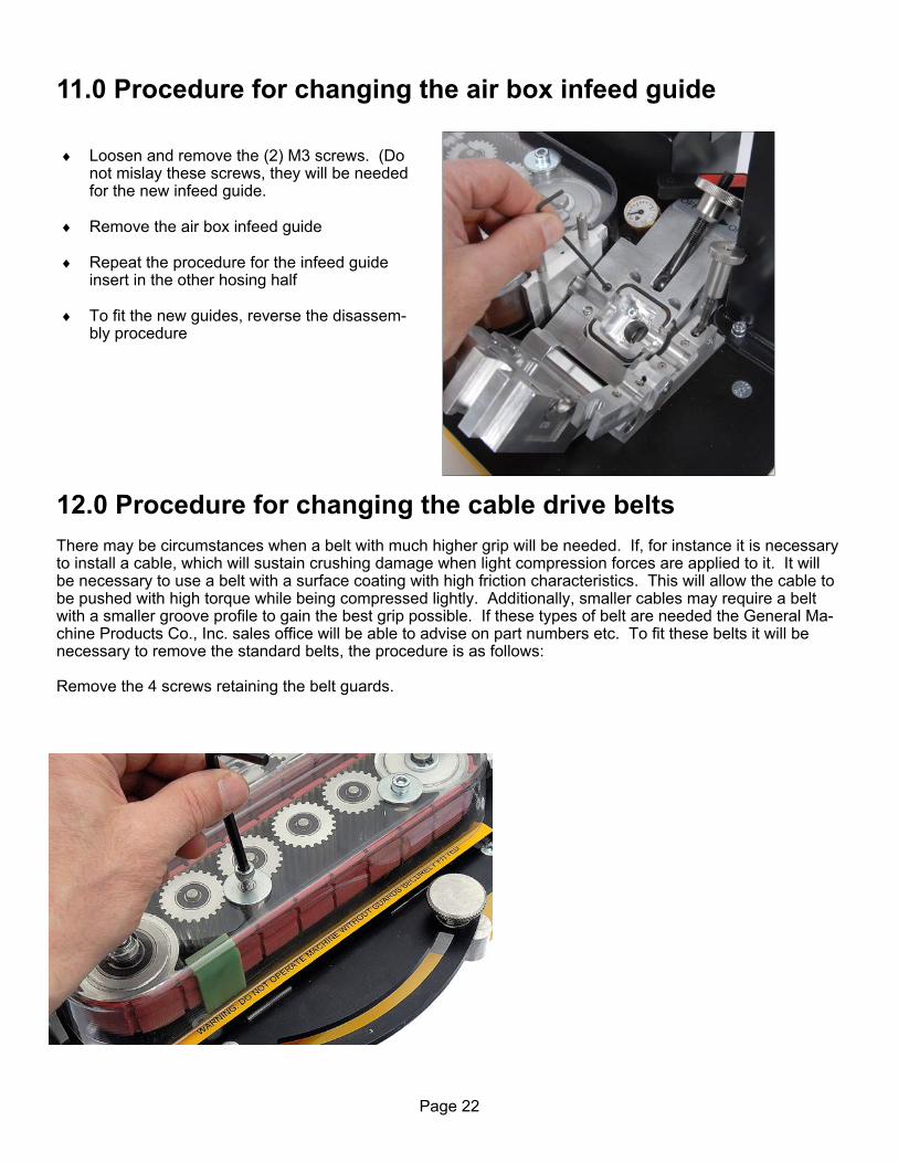
Loosen and remove the (2) M3 screws. (Do not mislay these screws, they will be needed for the new infeed guide.
Remove the air box infeed guide Repeat the procedure for the infeed guide
insert in the other hosing half To fit the new guides, reverse the disassem-
bly procedure
11.0 Procedure for changing the air box infeed guide
12.0 Procedure for changing the cable drive belts There may be circumstances when a belt with much higher grip will be needed. If, for instance it is necessary to install a cable, which will sustain crushing damage when light compression forces are applied to it. It will be necessary to use a belt with a surface coating with high friction characteristics. This will allow the cable to be pushed with high torque while being compressed lightly. Additionally, smaller cables may require a belt with a smaller groove profile to gain the best grip possible. If these types of belt are needed the General Ma-chine Products Co., Inc. sales office will be able to advise on part numbers etc. To fit these belts it will be necessary to remove the standard belts, the procedure is as follows: Remove the 4 screws retaining the belt guards.

Page 23
remove the belt guides
loosen and remove the tension nuts
loosen the tension screws
remove the idler pulleys and the belts
Place the new belt in position on the drive pulley, place the idler pulley around the other end and replace the idler pulley onto the tensioning shaft. Replace the tension nut and then tension as described in section 13.0. NOTE: NEVER POWER THE MACHINE UP OR RUN WITH THE GUARDS RE-MOVED. DOING SO MAY RESULT IN INJURY TO THE OPERATOR.

Page 24
13.0 Procedure for tensioning the drive belts
Place the new belt in position in over the pulleys and ensure the belt is correctly located in all the pulley grooves.
Tighten the tension screw with the tension nut slackened off slightly. This will begin to tighten the belt. Once the appropriate tension is reached, tighten the tension nut. Note tightening the nut will tighten the belt slightly, please set the tension screw to compensate for this.
The tension belt should have approximately 1/4” (6 mm) of slack. If necessary loosen the tension nut and re-adjust the tension screw until the cor-rect tension is achieved. Check that the tension nut is tight upon completion. (Note the belt tension should be checked periodi-cally without belt guides in place).
Replace the drive belt guards Replace the belt guides
Page 25
1
2
3
5 6
4
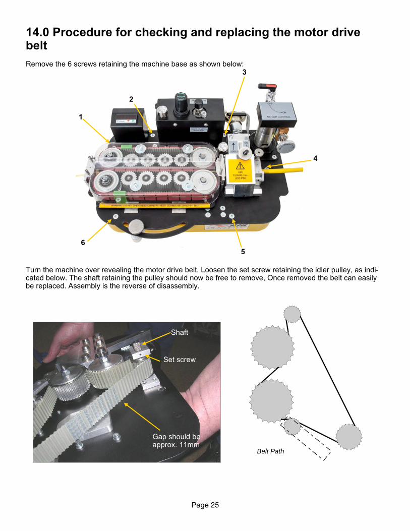
Belt Path
14.0 Procedure for checking and replacing the motor drive belt Remove the 6 screws retaining the machine base as shown below:
Turn the machine over revealing the motor drive belt. Loosen the set screw retaining the idler pulley, as indi-cated below. The shaft retaining the pulley should now be free to remove, Once removed the belt can easily be replaced. Assembly is the reverse of disassembly.
Set screw
Shaft
Gap should be approx. 11mm

Page 26
15.0 Tensioning of the air motor drive belt. There should be no need to alter the belt tensioning device providing it creates a deflection in the belt. However if adjustments are required of the belt tensioner it would require the removal of the air chamber as-sembly to gain access to its mounting screw through the top plate. Slacken the M6 CSK screw and rotate the tensioner housing to pre load the arm to create the desired deflection (See photos of adjusted belt). When the drive belt is removed it is an ideal opportunity to check the free rotation of all the idler and driven pulleys. Also the free operation of the close arm assembly.

Page 27
16.0 Procedure for checking/refilling/adjusting the oil level of the air lubricator
Do NOT run the machine without oil in the lubricator. Doing so will reduce machine perfor-mance while causing excessive wear and premature failure of the air motor. The machine should NOT be tipped onto its side or upside down as this will cause unwanted oil leakage into the pneumatic air lines. To check the lubricator oil level there is a slot in the front of the control housing. (see Fig. 1) Through this the oil level should be visible. Alternatively, while removing/changing the battery the bowl (see Fig. 2) will be clearly visible through the opening for the battery box in the control housing (see Fig. 3). Check that the oil is not below the minimum and not above the maximum permitted level, the operator may find a flashlight useful to assist.
1 2 3
Remove the fill screw and refill as required with correct oil grade (FD22 – HG32). Important: Hand tighten fill screw only. Overtightening can strip the fill screw thread.

Page 28
The amount of lubricating oil added to the air by the lubricator unit is adjustable. This is via the small knob on the top of the unit, as shown in the picture below. The knob is labelled + and -, this will either increase or decrease the amount of oil added to the air. The opti-mum amount of added oil is three (3) drops per minute and oil is only added while the machine is in opera-tion. The operator can observe the oil being added via the sight glass just below the knob. If more than three (3) drops per minute is being added, turn the knob in the minus direction until the correct amount is added. Turn the knob in the plus direction if less than three (3) drops per minute is added. Note: At the recommended oil drip rate of 3 drops per minute, oil will be seen dripping from the air exhaust port of the motor. This is normal and is an indication that the system is getting sufficient lubrication.
Lubricator Adjust
Lubricator Fill
Air Exhaust Port
Page 29
17.0 Monthly service – check list This section is included in the manual for your convenience, there follows a list of suggested checks, it is rec-ommended that these checks be carried out on a regular basis, depending on use. Monthly checks are con-venient; a few minutes can be set aside on the same day of each month to complete these simple checks. The next section of this manual is an empty table, the dates when these checks and all other service and re-pair jobs are completed can be entered into the spaces provided in this table. This will give the user a record of what service has been carried out and when. 1. Check the tool box, ensure all tools and interchangeable parts are present, clean and ready for use. 2. Remove the clear belt guards, clean the outside of the machine and replace. 3. Check the slide mechanism operates smoothly, lubricate if necessary with a dry film lubricant. 4. Clean the exposed threads on the swing bolts that hold the air box and microduct clamp assembly togeth-
er. Add a smear of grease/oil to prevent build up of surface corrosion and to ensure smooth operation of the thumb nuts.
5. Check the cable drive belt tension.

Page 30
18.0 SERVICE HISTORY RECORD
Service no Date Carried out by Record of service/repair

Page 31
Fit the appropriate plug as shown (see Appendix for plug number)
Fit the air box seal, microduct and mi-croduct seal in position as for normal cable installation
19.0 Microduct integrity and Lubrication This is entirely the responsibility of the operator. To be sure that the microduct into which the cable is to be inserted is installed appropriately, it is recommend-ed that its integrity and lubrication be checked. i.e. check that the microduct is: 1. Not blocked 2. Not squashed 3. Continuous (i.e. it has not been fractured somewhere along its route and the fractured ends separated) 4. Also check that any joins are pressure tight 5. Finally check that the microduct is appropriately lubricated. The easiest and most straightforward way to complete these checks is to set the machine up for a normal ca-ble insertion but fit a seal in place of the cable. The microduct can then be pressurized without running the belt drive. CAUTION: ANY OBJECT INADVERTENTLY LEFT IN THE MICRODUCT DURING
THE MICRODUCT LAYING MAY BE EXPELLED FROM THE END OF THE MI-
CRODUCT WITH HIGH FORCE AND VELOCITY. IT IS IMPERATIVE THAT NO
PERSONNEL BE IN THE VICINITY OF THE END OF THE MICRODUCT OR THAT A
SUITABLE DEVICE IS FITTED TO THE END OF THE MICRODUCT TO ARREST
ANY EXPELLED OBJECT.
The checks listed at 1-4 (inclusive) above may all be carried out at the same time using one check. The procedure is outlined below. Set up the air box and microduct clamp as shown right. When the air box has been set up as shown in the photo, the air box and microduct clamp should be closed as for usual cable installation.
Page 32
The air box and microduct clamp are now set up to blow air through the microduct. Connect the air as for normal blowing. Make sure there are personnel at the other end of the microduct run, and that they are aware that the air is to be turned on. Make sure that a suitable device is fitted to prevent injury should any object be expelled from the far end of the microduct. The far end of the microduct run should be monitored, air should be leaving the microduct under reasonable pressure. The minimum pressure required will vary with the length of microduct in the run, the friction char-acteristics of the microduct and the cable and the lubrication being used. However, as a starting point the air leaving the far end of the microduct should be (at least) similar to a light breeze. Bear in mind that if the mi-croduct run is of considerable distance, it may take a few minutes for the air to reach the far end of the mi-croduct. If after waiting a suitable time there is no air leaving the far end of the microduct, this would indicate that there is a blockage or similar obstruction in the microduct run, or, that the microduct is fractured. In either case the fault should be corrected before any attempt is made to blow cable down the microduct. Once the microduct integrity has been confirmed by the method outlined above. The microduct may be lubri-cated. Open the air box and microduct clamp assembly, as shown in the sketch above, withdraw the microduct and raise it so that the lubricant will pour into it easily and not overflow from the top. Pour lubricant of recom-mended quality and quantity down the microduct (A recommended quantity is 100ml per 1km of microduct length). Insert a suitable foam plug into the microduct and put the microduct back into the air box and mi-croduct clamp as shown in the sketch above. The air box and microduct clamp assembly are now set up to blow the foam plug through the microduct, the foam plug will help to deposit an even coating of lubricant to the inside walls of the microduct. Connect the air as for normal blowing. Make sure there are personnel at the other end of the microduct run, and that they are aware that the air is to be turned on. Make sure that a suitable device is fitted to prevent injury should any object be expelled from the far end of the microduct. When the foam plug has been expelled from the far end of the microduct run, cable can be installed into the microduct. Note: when the air is turned off, after checking the microduct integrity and sending the foam plug down the microduct to spread the lubricant, it may take some time for the pressure in the microduct to dissipate. Time must be allowed for the pressure to fall back to low levels.

Page 33
20.0 Recommended spares list
1. Microduct –‘O’ Rings – See Appendix 1 2. Cable Seal – See Appendix 1
3. Coated Cable Drive Belts – See Appendix 1
4. 2 mm cord seal – See Appendix 1
5. 315 mA Fuses - P/N 89593
6. Motor Drive Belt - P/N 34742
For spare parts always quote the machine type and serial number and contact: General Machine Products Co., Inc. 3111 Old Lincoln Hwy Trevose, Pa 19053 TEL: 215-357-5500 FAX 215-357-6216 E-MAIL: [email protected] Website: www.gmptools.com

Page 34
21.0 Troubleshooting Q Drive Belts will not move; A Check that the air supply is connected to both the motor circuit and airbox input.
If this is the case, with the air motor ball valve and flow control valve closed, increase the pressure on the torque control. Does pressure show on the pressure gauge? If not then this suggests a connection problem between the input and the regulator. Now try opening the ball valve, is air ejected from the exhaust? Again if not there is a connection prob-lem here. Open the flow control valve so the motor begins to turn, if the motor turns but the drive belts do not, this would suggest an issue with the motor drive belt.
Q Cannot achieve a reasonable speed of cable installation; A Check integrity of microduct installation Route too complex Check cable inserts and seals correct size for cable used. Is air supply sufficient – 15bar can be maintained on air gauge. Cable free from entering “Air Steam” – No resistance Fill ratio of the microduct Belts slipping – Close Arm not correctly set, there may be contamination on the belts, or belts worn.

Page 35
MICRODUCT COLLET AND CLAMP ASSEMBLIES 89310 MICRODUCT COLLET AND CLAMP ASSEMBLY 05mm O.D. 89311 MICRODUCT COLLET AND CLAMP ASSEMBLY 07mm O.D. 89312 MICRODUCT COLLET AND CLAMP ASSEMBLY 08mm O.D. 89319 MICRODUCT COLLET AND CLAMP ASSEMBLY 08.5mm O.D. 89313 MICRODUCT COLLET AND CLAMP ASSEMBLY 10mm O.D. 89314 MICRODUCT COLLET AND CLAMP ASSEMBLY 12mm O.D. 89315 MICRODUCT COLLET AND CLAMP ASSEMBLY 12.7mm O.D. 89316 MICRODUCT COLLET AND CLAMP ASSEMBLY 14mm O.D. 89317 MICRODUCT COLLET AND CLAMP ASSEMBLY 16mm O.D. 89318 MICRODUCT COLLET AND CLAMP ASSEMBLY 18mm O.D. CABLE GUIDE ASSEMBLIES 89305 CABLE GUIDE, 2.5mm DIAMETER 89306 CABLE GUIDE, 2.5 TO 3.0mm DIAMETER 89307 CABLE GUIDE, 3.0 TO 6.4mm DIAMETER 89303 CABLE GUIDE, 6.0 TO 8.5mm DIAMETER 89304 CABLE GUIDE, 8.5 TO 11mm DIAMETER CABLE SEAL COLLET ASSEMBLY 89374 CABLE SEAL COLLET ASSEMBLY 2.5 TO 3.0mm DIAMETER 89375 CABLE SEAL COLLET ASSEMBLY 3.0 TO 3.8mm DIAMETER 89376 CABLE SEAL COLLET ASSEMBLY 3.8 TO 5.0mm DIAMETER 89377 CABLE SEAL COLLET ASSEMBLY 5.0 TO 6.4mm DIAMETER 89378 CABLE SEAL COLLET ASSEMBLY 6.4 TO 8.0mm DIAMETER 89379 CABLE SEAL COLLET ASSEMBLY 8.0 TO 9.5mm DIAMETER 89373 CABLE SEAL COLLET ASSEMBLY 9.5 TO 11.0mm DIAMETER SPARE CABLE SEAL 89510 CABLE SEAL 2.5 TO 3.0mm (PACK OF 5) 89511 CABLE SEAL 3.0 TO 3.8mm (PACK OF 5) 89512 CABLE SEAL 3.8 TO 5.0mm (PACK OF 5) 89513 CABLE SEAL 5.0 TO 6.4mm (PACK OF 5) 89514 CABLE SEAL 6.4 TO 8.0mm (PACK OF 5) 89516 CABLE SEAL 8.0 TO 9.5mm (PACK OF 5) 89517 CABLE SEAL 9.5 TO 11.0mm (PACK OF 5) DRIVE BELTS (sold in pairs) 30952 DRIVE BELT, 3-11mm DIAMETER CABLE 30953 DRIVE BELT, 1-5mm DIAMETER CABLE SPARE MICRODUCT SEAL O RING 89549 MICRODUCT SEAL O RING 05mm DIAMETER (PACK OF 5) 89550 MICRODUCT SEAL O RING 07mm DIAMETER (PACK OF 5) 89551 MICRODUCT SEAL O RING 08-08.5mm DIAMETER (PACK OF 5) 89552 MICRODUCT SEAL O RING 10 mm DIAMETER (PACK OF 5) 89553 MICRODUCT SEAL O RING 12 - 12.7mm DIAMETER (PACK OF 5) 89554 MICRODUCT SEAL O RING 16mm DIAMETER (PACK OF 5) 89558 MICRODUCT SEAL O RING 18mm DIAMETER (PACK OF 5) SPARE CORD SEAL 89691 SEAL CORD 2mm DIAMETER X 3’ (1M) LONG
APPENDIX 1 - Cable and microduct insert selection chart This section lists the appropriate inserts collets etc required for a given cable/microduct combination.
Page 36
APPENDIX 2 - Recommended torque control settings procedure This section details a procedure to assist in determining the correct torque control pressure setting when in-stalling a cable which has not been installed before, and, whose characteristics are unknown. Select a sample of the cable to be used. Pass the cable through the machine as described in the manual. Feed the cable into the beginning of a length of sample microduct (say 5 meters long). Seal the open end of the microduct. Initially set the torque control pressure as follows: 2.5 – 5mm diameter cable = 2 bar 5 – 8mm diameter cable = 4 bar 8 – 11mm diameter cable = 6 bar Please note this is a guide, these initial settings could potentially damage the cable. Discard any cable dam-aged during this procedure. Start the machine. Drive the cable hard into the sealed end of the sample length of microduct. The rollers will stop turning, this is because the torque limit has been reached. Repeat this procedure, each time in-creasing the torque control pressure setting a little further. Eventually, the cable will buckle. The torque con-trol pressure setting is now a little too high. Reduce the pressure a little. This is the optimum setting. Note: This method may also be used to set the clamping force of the belts on the cable. Initially, the clamp arm lever should be set so that the belts press very lightly onto the cable. Carry out the test outlined above (drive the cable into the closed end of a sample microduct). The belts will slip. Repeat this procedure, each time increasing slightly, the pressure the belts apply to the cable. Eventu-ally the belts will stop turning because the torque limit has been reached. It is worth noting at this stage that this approach may result in a great deal of force being applied to the cable. More than the cable can with-stand without sustaining damage, sometimes it may be that the cable may be protected from buckling by a combination of torque control setting and slip. The main purpose of the exercise is to install the cable as far as possible without causing damage to the outer sheath, in some circumstances a compromise may be found that uses a degree of torque control and slip.

Page 37
• Press and hold both and buttons. o After 5 seconds ‘ProG’ will be displayed. Releasing the buttons will display ‘no’ • Press o ‘Yes’ is displayed • Hold and press o ‘InPol’ is displayed • Press until ‘nPn’ is displayed • Hold and press o ‘Filter’ is displayed • Press until ‘oFF’ is displayed • Hold and press o ‘InPut’ is displayed • Press until ‘Cnt.dir’ is displayed • Hold and press o ‘FAc.Cnt’ is displayed • Press • Enter value 00.0091 for meters, 00.0299 for feet o Use to move to next digit o Use to increment digit (this instruction applies to all following number inputs) Hold and press o ‘diV.Cnt’ is displayed • Press • Enter value 01.0000 • Hold and press o ‘dP.Cnt’ is displayed • Press until ‘0’ is displayed • Hold and press o ‘rES.Cnt’ is displayed • Press until ‘MAnrE’ is displayedat • Hold and press o ‘FAc.tAc’ is displayed • Press • Enter value 00.0091 for meters, 00.0299 for feet • Hold and press o ‘diV.tAc’ is displayed • Press • Enter value 01.0000 • Hold and press o ‘dP.tAc’ is displayed • Press until ‘0’ is displayed • Hold and press o ‘disPm’ is displayed • Press until ‘Min-1’ is displayed • Hold and press o ‘Wait0’ is displayed
APPENDIX 3 Counter/Ratemeter Programming Instructions
(over)

Page 38
• Press
• Enter value 01.0
• Hold and press
o ‘EndPro’ is displayed
• Press un l ‘YES’ is displayed
• Hold and press
o Programming completed
OR
• Press un l ‘no’ is displayed
• Hold and press
o Programming mode restarted

Page 39

Page 40
GMP • 3111 Old Lincoln Hwy • Trevose, PA 19053 • USA TEL: +1-215-357-5500 • FAX: +1-215-357-6216 • EMAIL: [email protected]