operation and maintenance manual universal i series
TRANSCRIPT

Operation and Maintenance ManualUniversal I Series
Positive Displacement Pumps
Read and understand this manualprior to installing, operating or servicing this equipment.

611 Sugar Creek RoadDelavan, WI 53115 USA
Tel: (800) 252-5200 (within the USA) • (262) 728-1900Fax: (800) 252-5012 (within the USA) • (262) 728-4904
E-mail: [email protected]: www.spxprocessequipment.com
Information contained in this manual is subject to changewithout notice and does not represent a commitment onthe part of Waukesha Cherry-Burrell. No part of thismanual may be reproduced or transmitted in any form orby any means, electronic or mechanical, includingphotocopying and recording, for any purpose, without theexpress written permission of Waukesha Cherry-Burrell.
Copyright © 2006 All Rights Reserved.
Gore-Tex is a registered trademark of W.L. Gore & Associates, Inc.Kalrez is a registered trademark of DuPont Dow Elastomers.Chemraz is a registered trademark of Greene, Tweed & Co.
Revised Date: January 2006Publication: 95-03002

January 2006 Table of Contents95-03002 Page 1
Table of ContentsSafety . . . . . . . . . . . . . . . . . . . . . . . . . . . . . . . . . . . . . . . . . . . . .31 Warranty and Receiving . . . . . . . . . . . . . . . . . . . . . . . . . . .42 Installation . . . . . . . . . . . . . . . . . . . . . . . . . . . . . . . . . . . . . .53 Start-Up Check List . . . . . . . . . . . . . . . . . . . . . . . . . . . . . .104 Troubleshooting a Pumping System . . . . . . . . . . . . . . . .11
5 Operation . . . . . . . . . . . . . . . . . . . . . . . . . . . . . . . . . . . . . .16Lubrication . . . . . . . . . . . . . . . . . . . . . . . . . . . . . . . . . . . . . .16Fluid Head DisassemblyAll Models . . . . . . . . . . . . . . . . . . . . . . . . . . . . . . . . . . . . . .18Model 320-324 Body Disassembly . . . . . . . . . . . . . . . . . . .19Model 323A Aseptic Body Disassembly . . . . . . . . . . . . . . .19Fluid Head AssemblyMost Models . . . . . . . . . . . . . . . . . . . . . . . . . . . . . . . . . . . .20Flushing Connection . . . . . . . . . . . . . . . . . . . . . . . . . . . . . .21
6 Maintenance . . . . . . . . . . . . . . . . . . . . . . . . . . . . . . . . . . . .22Visual Checks . . . . . . . . . . . . . . . . . . . . . . . . . . . . . . . . . . .22“Feel” Checks. . . . . . . . . . . . . . . . . . . . . . . . . . . . . . . . . . . .23Seal Maintenance . . . . . . . . . . . . . . . . . . . . . . . . . . . . . . . .24O-Ring - Seals . . . . . . . . . . . . . . . . . . . . . . . . . . . . . . . . . . .24Mechanical SealsUniversal Series. . . . . . . . . . . . . . . . . . . . . . . . . . . . . . . . . .26Model 320, 324 . . . . . . . . . . . . . . . . . . . . . . . . . . . . . . . . . .29Model 323A Aseptic. . . . . . . . . . . . . . . . . . . . . . . . . . . . . . .30Annual Maintenance . . . . . . . . . . . . . . . . . . . . . . . . . . . . . .32
7 Factory Reconditioning. . . . . . . . . . . . . . . . . . . . . . . . . . .33
8 Disassembly Procedures . . . . . . . . . . . . . . . . . . . . . . . . .34Shaft Bearing and GearsAll Models . . . . . . . . . . . . . . . . . . . . . . . . . . . . . . . . . . . . . .34Shaft Removal . . . . . . . . . . . . . . . . . . . . . . . . . . . . . . . . . . .34All Models except 320,323A and 324 . . . . . . . . . . . . . . . . .35Models 320, 323A and 324 . . . . . . . . . . . . . . . . . . . . . . . . .36
9 Assembly Procedures . . . . . . . . . . . . . . . . . . . . . . . . . . . .37Models 6, 12, 15, 18, 22, 30, 32, 34 and 33A Aseptic . . . . .37Models 320, 323A, 324 Shaft . . . . . . . . . . . . . . . . . . . . . . .39Gear and Gear Cover AssemblyAll Models . . . . . . . . . . . . . . . . . . . . . . . . . . . . . . . . . . . . . .43Back Face Clearance. . . . . . . . . . . . . . . . . . . . . . . . . . . . . .44

Table of Contents January 2006Page 2 95-03002
10 Repair/Reference Tables . . . . . . . . . . . . . . . . . . . . . . . . . 46Relief Cover . . . . . . . . . . . . . . . . . . . . . . . . . . . . . . . . . . . . 47Jacketed Cover. . . . . . . . . . . . . . . . . . . . . . . . . . . . . . . . . . 51Illustrated Parts Lists006-014-015-018-024-U1 Pump Parts . . . . . . . . . . . . . . . . 52030-034-033-U1 Pump Parts . . . . . . . . . . . . . . . . . . . . . . . 62040-U1 Pump Parts . . . . . . . . . . . . . . . . . . . . . . . . . . . . . . 74060-064-130-134-U1 Pump Parts . . . . . . . . . . . . . . . . . . . 86220-224-223-U1 Pump Parts . . . . . . . . . . . . . . . . . . . . . . . 96320-324-323-U1 Pump Parts . . . . . . . . . . . . . . . . . . . . . . 108Universal I Pump Dimensions . . . . . . . . . . . . . . . . . . . . . 116Tru-Fit™ UI Pump Dimensions. . . . . . . . . . . . . . . . . . . . . 118
NOTE: Waukesha Pump CIP Series require use of the CIP Addendum 95-03039 in conjunction with this manual.

January 2006 Safety95-03002 Page 3
SafetyWarnings, Cautions, and Notes are contained in this manual. To avoid serious injury and/or possible damage to equipment, pay attention to these messages.
READ AND UNDERSTAND THIS MANUAL PRIOR TO INSTALLING, OPERATING, OR MAINTAINING THIS PUMP.
WARNING: Hazards or unsafe practices which COULD result in severe personal injury or death and how to avoid it.
CAUTION: Hazards or unsafe practices which COULD result in minor personal injury or product or property damage.
NOTE: Important information pertaining directly to the subject. This is information to be aware of when completing the task.

Section 1 - Warranty and Receiving January 2006Page 4 95-03002
Section 1 - Warranty and Receiving
WAUKESHA CHERRY-BURRELL WARRANTY
Seller warrants its products to be free from defects in materials and workmanship for a period of one (1) year from the date of shipment. This warranty shall not apply to products which require repair or replacement due to normal wear and tear or to products which are subjected to accident, misuse or improper maintenance. This warranty extends only to the original Buyer. Products manufactured by others but furnished by Seller are exempted from this warranty and are limited to the original manufacturer’s warranty.
Seller’s sole obligation under this warranty shall be to repair or replace any products that Seller determines, in its discretion, to be defective. Seller reserves the right either to inspect the products in the field or to request their prepaid return to Seller. Seller shall not be responsible for any transportation charges, duty, taxes, freight, labor or other costs. The cost of removing and/or installing products which have been repaired or replaced shall be at Buyer’s expense.
Seller expressly disclaims all other warranties, express or implied, including without limitation any warranty of merchantability of fitness for a particular purpose. The foregoing sets forth Sellers entire and exclusive liability, and Buyer’ exclusive and sole remedy, for any claim of damages in connection with the sale of products. In no event shall Seller be liable for any special consequential incidental or indirect damages (including without limitation attorneys’ fees and expenses), nor shall Seller be liable for any loss of profit or material arising out of or relating to the sale or operation of the products based on contract, tort (including negligence), strict liability or otherwise.
FACTORY INSPECTION Each WAUKESHA pump is shipped completely assembled, lubricated and ready for use. (See OPERATION on page 17). The WAUKESHA pump is a precision product, designed to provide long, trouble-free service in a properly designed system with normal maintenance.
RECEIVING INSPECTON
Ports are covered at the factory to keep out foreign objects. If covers are missing or damaged, a thorough inspection of fluid head, by removing pump cover, is recommended. Be sure pumping head is clean and free of foreign material before rotating shaft.
LOSS OR DAMAGE If your pump has been lost or damaged in transit, file a claim at once with the delivering carrier and ask for an inspector to call. The carrier has signed the Bill of Lading acknowledging that the shipment has been received from us in good condition.
We will of course assist you in every way in collecting claims for loss, or damage, however, we are not responsible for the collection of claims or replacement of material.
WARRANTY Please read the Warranty statement to correctly determine if you have a claim. In warranty claims you must have a “Returned Goods Authorization” (RGA) from the manufacturer before any returns will be accepted. Your Distributor will help you in a warranty problem.

January 2006 Section 2 - Installation95-03002 Page 5
Section 2 - InstallationThe installation of your Waukesha pump and its piping system should follow good practice to give optimum performance, and to be in accordance with local codes and restrictions.
All system equipment, such as motors, sheaves, drive couplings, speed reducers, etc., must be properly sized to ensure satisfactory operation of your Waukesha pump within its limits.
PUMP & DRIVE INSTALLATION
The installation of your Waukesha pump and its piping system should follow good practice to give optimum performance.
Pumps of this type and size are generally mounted on a common base plate with the drive.
NOTE: Pump can be mounted in any of three positions without removing shafts. However, unless it is an RF pump (14, 34, 64, 134, 224 or 324), mounting it on its side will require more lubrication before operating (see OPERATION on page 16).
The unit can be installed in the plant location in several ways:
Permanent installation on foundation with bolts and grout. (Level unit before grouting).
Leveling and/or vibration isolation pads.
CAUTION: Waukesha pumps are positive displacement, low slip design and will be severely damaged if operated with closed valves in discharge or inlet lines. Pump warranty is not valid for damages caused by a hydraulic overload from operation or start-up with a closed valve in the system.
WARNING: Full coupling guards must be installed to isolate operators and maintenance personnel from rotating components. Coupling guards are provided with Waukesha pumps as a part of a complete pump and drive package.
Coupling Guard
Coupling Guard

Section 2 - Installation January 2006Page 6 95-03002
Adjustable leg base, commonly used for sanitary pumps. For washdown under base. Can be easily moved or repositioned.
Portable bases, for movement to different locations.
GOOD PIPING PRACTICE
All piping to the pump should be supported independently to minimize the forces exerted on the pump. Such forces can cause misalignment of pump parts and lead to excessive wear of rotors, bearings and shafts.
Piping support
Weight of piping and fluid — support piping independently with hangers or pedestals.
Thermal expansion of piping — can cause tremendous forces. Use thermal expansion joints to minimize forces on pump.
Flexible joints can also be used to limit the transmission of mechanical vibration. Anchor free ends of any flexible hose in system.
Piping Layout
Inlet side — slope piping up to inlet to avoid air pocket.
Inlet side — use check valves to keep inlet line full particularly with low viscosity fluids, and in start-stop operation.
Coupling Guard
Coupling Guard
WARNING: To avoid serious injury, do not install or service pump unless all power is off and locked out.

January 2006 Section 2 - Installation95-03002 Page 7
Inlet Vacuum Service — use check valve on outlet side. Prevents backflow (air or fluid). Facilitates initial start-up (minimizes differential pressure pump must supply to start flow).
"Isolation" valves — permit pump maintenance and removal safely and without emptying entire system.
Relief Valve
To protect the pump and piping system against excessive pressure, a relief valve should be installed. An integral relief valve, designed to bypass the fluid internally from the pump outlet to the inlet, should not be used on applications where the discharge must be closed for more than a few minutes. Prolonged operation of the pump with closed discharge will cause heating of the fluid circulating through the relief valve. When such operation is necessary, the relief valve, whether integral, attachable, or line-mounted, should discharge externally through piping connected to the fluid source, or if that is not practical, into the inlet piping near the source.
A particular relief valve design will have a characteristic curve such as shown. The "cracking pressure" can usually be set by spring adjustment, or by adjustable pneumatic pressure, etc. Flow will begin to bypass when this "cracking pressure" is reached. As flow increases through the bypass, the system pressure will also increase.
The pressure increase for a given valve design depends on the valve setting, the flow rate, and the viscosity of the fluid being pumped. If the full-flow bypass pressure exceeds the maximum allowable for the particular pump and piping system, an oversize attachable relief valve may sometimes be used to limit the full-flow bypass pressure to an acceptable value.
Inlet Side — Strainers and Traps
Inlet side strainers and traps can be used to prevent pump damage from foreign matter. Selection must be carefully made as clogging can easily occur, restricting the inlet, causing cavitation and flow stoppage.
Pressure Gauges — Install gauges whenever possible!
Pressure and vacuum gauges provide the easiest way to tell you something about the pump operation.
• Normal or abnormal pressures• Overload conditions indication of flow• Changes in pump condition• Changes in system conditions• Changes in fluid viscosity

Section 2 - Installation January 2006Page 8 95-03002
Alignment of Pump to Drive
Pumps and drives which are ordered from the factory and mounted on a common base plate are accurately aligned before shipment. The alignment should be rechecked after the complete unit has been installed and the piping completed. Periodic rechecking is advisable during the pump service life.
In-line Drives
For initial pump installation, and for rechecking alignment, the following steps are advised:
Use a flexible coupling to connect the drive to the pump. Many different types are available, including couplings with slip or overload provision.
A flexible coupling is used to compensate for end play and small differences in alignment. The pump and drive shaft should be aligned as closely as is possible.
Check angular alignment
Using feeler gauges, or taper gauges. Adjust to get equal dimension at all points. At the same time set space between coupling halves to manufacturer’s recommended distance.
Check parallel misalignment:
Use straight edges and shims.
After piping is complete, and drive and couplings are aligned, turn pump shaft manually to see if it turns freely without binding.
WARNING: To avoid serious injury, do not install or service pump unless all power is off and locked out.
RubberCushioned
GearType
FlexibleMember Detent
SlipOverload
FluidCoupling
Feeler or Taper Gauge
Shimas
needed
Check at 4 points aroundcoupling - every 90°
Move drive as needed
Shim height as needed
WARNING: Keep fingers out of ports.

January 2006 Section 2 - Installation95-03002 Page 9
Check rotation direction of drive to see that pump will rotate in proper direction. ("Liquid End" of pump is shown below.)
NOTE: Covers have been removed for illustration purposes only. The pump cannot be operated with the cover removed.
Figure 1
Determine rotation direction by looking at the motor coupling.
Connect coupling halves and install coupling guard.
Aligning belt and chain drives
Using straight-edges and visual check. Move drive to correct any angular and parallel misalignment
Figure 2
After piping is complete and before belts are installed, turn pump shaft manually to see that it turns freely.
Check rotation direction of pump to see that pump will rotate in proper direction (see Figure 1). Install belts and tension them correctly. Install belt guard before operation.
Top ShaftDrive
Lower ShaftDrive
Lower Shaft Drive
Top Shaft Drive
Keepdistance
to minimum

Section 3 - Start-up Check List January 2006Page 10 95-03002
Section 3 - Start-up Check ListThe Waukesha Pump is a positive displacement pump and can develop very high pressures. To protect lines, equipment and personnel, certain precautions must be taken.
1. Review Section 2, particularly “Relief Valves”. Install relief valves if needed in system.
2. Check that piping and pump are clean and free of foreign material, such as welding slag, gaskets, etc. Do not use pump to flush system.
3. See that all piping connections are tight and leak-free. Where possible, check system with "non-hazardous" fluid.
4. Check to see that pump and drive are lubricated. See Section 5. Check Drive Lubrication Instruction.
5. Check that all guards are in place and secure.
6. Seals: Double mechanical and double O-ring seals with flushing require adequate supply and flow of clean flushing fluids.
7. See that all valves are open on discharge system, and that free flow path is open to destination.
8. See that all valves are open on inlet side, and that fluid can reach pump.
9. Check direction of pump and drive rotation. (See page 10)
10. Start pump drive. Where possible, start at slow speed, or jog.
Check to see that liquid is reaching pump within several minutes. If pumping does not begin and stabilize, check items under "No Flow" or "Insufficient Flow" in Section 4 - Troubleshooting a Pumping System (page 12).

January 2006 Section 4 - Troubleshooting a Pumping System95-03002 Page 11
Section 4 - Troubleshooting a Pumping SystemOnce a pump is properly selected and installed in a system, operation should be trouble free. However, in existing systems, or as pump and system conditions change, problems may develop. Following are some troubleshooting hints to help identify and solve problems.
WARNING: To avoid serious injury, do not install or service pump unless all power is off and locked out.
WARNING: To avoid possible serious injury, shut off and drain product from pump prior to disconnecting piping..
Problem Probable Causes Solutions
No flow, pump not turning 1. Drive motor not running.
2. Keys sheared or missing.
3. Drive belts, power transmission components slipping or broken.
4. Pump shaft, keys, or gears sheared.
1. Check resets, fuses, circuit breakers.
2. Replace.
3. Replace or adjust.
4. Inspect: replace parts.
No flow, pump turning Wrong direction of rotation Reverse
No flow, pump not priming 1. Valve closed in inlet line.
2. Inlet line clogged or restricted.
3. Air leaks due to bad seals or pipe connections.
4. Pump speed too slow.
5. Liquid drains or siphons from system during off periods.
1. Open valve.
2. Clear line, clean filters, etc.
3. Replace seals; check lines for leakage (can be done by air pressure or by filling with liquid and pressurizing with air).
4. Increase speed. Filling inlet lines with fluid may allow initial start-up. Foot valve may solve start-up problems permanently.
5. Use foot valve or check valves.

Section 4 - Troubleshooting a Pumping System January 2006Page 12 95-03002
No flow, pump not priming 1. "Air" lock. Fluids which "gas off", or vaporize, or allow gas to come out of solution during off periods.
2. Extra clearance rotors, worn pump.
3. Net inlet pressure available too low.
4. On "Vacuum" inlet system: On initial start-up, atmospheric “blow back“ prevents pump from developing enough differential pressure to start flow.
1. Manual or automatic air bleed from pump or lines near pump.
2. Increase pump speed, use foot valve to improve priming.
3. Check net inlet pressure available, net inlet pressure required, recalculate system. Change inlet system as needed.
4. Install check valve in discharge line.
No flow 1. Relief valve not properly adjusted, or held off seat by foreign material (flow is being recirculated to inlet).
1. Adjust or clear valve.
Insufficient flow 1. Speed too low to obtain desired flow.
2. Air leak due to bad seals or pipe connections.
1. Check flow-speed curve.
2. Replace seals, check inlet fittings.
Fluid vaporization (“starved“ pump inlet)
1. Strainers, foot valves, inlet fittings or lines clogged.
2. Inlet line size too small, inlet line too long. Too many fittings or valves. Foot valve, strainers too small.
3. Net inlet pressure available at pump too low.
4. Net inlet pressure required by pump too low.
5. Net inlet pressure available too low.
6. Fluid viscosity greater than expected.
7. Fluid temperature higher than expected (vapor pressure higher).
1. Clear lines. If problem continues, inlet system may require change.
2. Increase inlet line size. Reduce length, minimize direction and size changes, reduce number of fittings.
3. Raise liquid level in source tank.
4. Increase by raising or pressurizing source tank.
5. Select larger pump size with smaller net inlet pressure required.
6. Reduce pump speed and accept lower flow, or change system to reduce line losses.
7. Reduce temperature, reduce speed and accept lower flow or change system to increase net inlet pressure available.
Problem Probable Causes Solutions

January 2006 Section 4 - Troubleshooting a Pumping System95-03002 Page 13
Insufficient flow. Fluid being bypassed somewhere
1. Relief valve not adjusted or jammed.
2. Flow diverted in branch line, open valve, etc.
1. Adjust or clear.
2. Check system and controls.
Insufficient flow. High slip 1. Hot (HC) or extra clearance rotors on "cold" fluid, and/or low viscosity fluid.
2. Worn pump.
3. High pressure.
1. Replace with standard clearance rotors.
2. Increase pump speed (within limits). Replace rotors, recondition pump.
3. Reduce pressure by system changes.
Noisy operation Cavitation
1. High fluid viscosity,High vapor pressure fluids,High temperature
2. Net inlet pressure available less than net inlet pressure required, see Engineering Manual
Air or gas in fluid
1. Leaks in pump or piping
2. Dissolved gas or naturally aerated products
Mechanical noises - Rotor to body contact.
1. Improper assembly
1. Slow down pump, reduce temperature, change system.
2. To increase net inlet pressure available or reduce net inlet pressure required.
1. Correct leaks.
2. Minimize discharge pressure. Also see "Cavitation" above.
1. Check clearance with shims.
Problem Probable Causes Solutions

Section 4 - Troubleshooting a Pumping System January 2006Page 14 95-03002
Noisy operation Rotor to body contact1. Distortion of pump due to
improper piping installation.
2. Pressure higher than rated.
3. Worn bearing.
4. Worn gears.
Rotor to rotor contact1. Loose or mis-timed gears,
twisted shaft, sheared keys, worn splines.
Relief valve chattering
Drive component noise-gear trains, chains, couplings, bearings.
1. Reassemble pump or re-install piping to assure free running.
2. Reduce pressure if possible.
3. Rebuild with new bearings. Lubricate regularly.
4. Rebuild with new gears. Lubricate regularly.
1. Rebuild with new parts.
Re-adjust, repair or replace.
Repair or replace drive train.
Pump requires excessive power (overheats, stalls, high current draw, breakers trip)
1. Higher viscous losses than expected.
2. Higher pressure than expected.
Fluid characteristics.
1. Fluid colder than expected, viscosity high.
2. Fluid sets up in line and pump during shut down.
3. Fluid builds up on pump surfaces (example, latex, chocolate, fondants).
1. If within pump rating, increase drive size.
2. Reduce pump speed. Increase line sizes.
1. Heat fluid. Insulate or heat trace lines. Use pump with more running clearances.
2. Insulate or heat trace line. Install “soft start” drive. Install recirculating bypass system. Flush with other fluid.
3. Use pump with more running clearance.
Problem Probable Causes Solutions

January 2006 Section 4 - Troubleshooting a Pumping System95-03002 Page 15
“Short” pump service life 1. High corrosion rate.
2. Pumping abrasives.
3. Speeds and pressures higher than rated.
4. Worn bearings and gears due to lack of lubrication.
5. Misalignment of drive and piping. Excessive overhung load or misaligned couplings.
1. Upgrade material of pump.
2. Larger pumps at slower speeds, can help.
3. Reduce speeds and pressures by changes in system.
4. Set up and follow regular lubrication schedule.
5. Check alignment of piping. Check drive alignment and loads. (page 10)
Problem Probable Causes Solutions

Section 5 - Operation January 2006Page 16 95-03002
Section 5 - Operation
NORMAL OPERATION Normal operation covers a speed range of 0 to 600 RPM and pressure range of 0 to 200 PSI. Temperature range with standard rotors is -40° to 200°F and with hot clearance rotors. 180° to 300°F. (For operation at higher temperatures, consult factory.)
LUBRICATION The gears are factory lubricated with ISO Grade 320, SAE 140, or AGMA Number 6EP oil at the quantity shown for top or bottom shaft mounts. (14, 34, 64, 134, 224 and 324 are filled for side mount). If you mount your pump other than top or bottom shaft drive, check oil level.
The bearings are factory greased with NLGI grade 2 grease.
Change oil every 500 hours. If pump is installed where moisture and condensation are heavy, change oil more frequently.
Bearings must be greased every 250 hours or less depending on moisture and condensation conditions. Excess grease will accumulate in the gear case and can be removed through the cleanout hole covered with plastic plug.
Figure 3 Upper Shaft Drive Position of Pump Shown
WARNING: Stop pump and lock out all power prior to servicing.
Upper Shaft Drive Oil Fill or Lower Shaft Oil Level
Sump Cleanout
Lower Shaft Drive Oil Fill or Upper Shaft Oil Level
Side Mount Position Oil Level
Side Mount Position Oil Fill

January 2006 Section 5 - Operation95-03002 Page 17
DRIVE LUBRICATION Refer to drive manufacturer’s manual shipped with unit.
CLEANING The Waukesha pump is designed to be completely disassembled for thorough and easy cleaning. Clean the pump every day or at the end of a process. Disassemble the fluid head as outlined. Remove and clean the O-rings, sleeves and pump seals.
NOTE: For hot or cold extremes use appropriate lubricant as shown in Table 1.
Table 1
Type Temperature Range
Oil ISO Grade 320, SAE 140, or AGMA
Number 6EP
-10° to 350°F(-23.3° to 176.6 °C)
Grease
Silicone -20° to 5°F(-28.8° to -15°C)
NLGI grade 2 5° to 350°F(-15° to 176.6 °C)
Table 2 - Oil Capacity (Gears)
ModelTop or Bottom Shaft
oz (ml)Side Mount
oz (ml)
6, 12, 14, 15, 18, 22 1.3 (40) 3.3 (100)
30, 32, 33A, 34 2 (60) 4 (120)
60, 62, 64 6 (170) 9.5 (280)
130, 132, 133A, 134 6 (170) 9.5 (280)
220, 222, 223, 224 11 (320) 20 (600)
320, 324, 323A 17 (500) 44 (1300)

Section 5 - Operation January 2006Page 18 95-03002
FLUID HEAD DISASSEMBLY - ALL MODELS
1. Shut off power, close isolation valves, and disconnect inlet and discharge lines.
2. Remove wing nuts using soft hammer to loosen them.
3. Remove cover, if it is stuck, loosen it with a soft hammer. Remove and discard cover O-ring.
4. Remove rotor retaining nuts. Use the special wrench supplied with pump and hit it sharply with a soft hammer to loosen nuts.
5. Orient rotors perpendicular to each other and remove rotor with both wings exposed first. Handle rotors with care to avoid knicks and scratches. If it is stuck tight, use a gear puller or hardwood lever behind rotor hub to force it off spline.
6. Remove pump body by pulling it straight off studs. Use a soft hammer to assist if body is stuck tight.
7. See Section 4 for seal disassembly procedure.
8. Clean and inspect body thoroughly.
Soft Hammer
O-Ring
Apply gear puller here
CAUTION: Body must be reassembled on bearing housing from which it was removed. Both are identified with same serial number.

January 2006 Section 5 - Operation95-03002 Page 19
MODEL 320 AND 324 BODY DISASSEMBLY
After removing the cover and rotors, remove the four bolts from each seal gland and slide the gland toward the gear case. Loosen the two socket head cap screws from the front of the body. Tap the body with a soft hammer to drive body loose from gear case and dowel pins.
MODEL 323 ASEPTIC BODY DISASSEMBLY
1. Disconnect flushing lines.
2. Remove cap screws from seal flush glands and slide glands back against gear case.
3. Loosen two socket head cap screws in front of body. Tap body with a soft hammer to drive body loose from gear case and dowel pins.
4. Thoroughly clean the shafts. Remove "flared end" to aid in seal removal.
CLEANING PROCEDURE
Use a basket or wash tank having the bottom covered with a rubber mat. Wash parts thoroughly with cleaning compound using brushes and plenty of fresh warm water at about 125°F. Rinse the parts thoroughly with 170°F water and store them to permit free draining and natural drying. Reassemble pump and sterilize it in accordance with accepted sterilizing practices. If chlorine solution (200 ppm available chlorine) is used, it should leave no residual deposits which would remain in the pump.
Capscrew (2)Gland Bolts (8)
File flared end
NOTE: Acid cleaners have a much higher metal corrosion rate andpump parts should remain in acid cleaning solutions no longer than necessary. Any strong inorganic mineral base acids that are harmful to your hands would be harmful to pump parts. Due to the high circulation required, Waukesha Fluid Handling recommends that its pumps not be used to recirculate cleaning solutions.

Section 5 - Operation January 2006Page 20 95-03002
FLUID HEAD ASSEMBLY - MOST MODELSSeal Assembly See SEAL MAINTENANCE for assembly procedure on all models.
Body Assembly1. Slide body over shafts and studs being careful seal components are not
knicked or knocked out of place. Press body firmly against gear case engaging dowels.
2. Model 320, 324 and 323A bodies are secured to the gearcase with 2 socket head cap screws thru the head. (For seals see page 31 thru 33).
Rotor Assembly
Assemble a rotor onto shaft engaging the large spline tooth with the large groove in rotor. Rotate shaft until rotor wings are on vertical centerline. Install the second rotor and secure both with rotor retaining nuts (clockwise). Lock the nuts. (See torque table on page 49).
NOTE: CIP pumps have right hand and left hand nuts (12, 22, 32, 62, 132 and 222).
Cover Assembly1. Install O-ring in cover groove.
2. Mount cover on studs and push it against body being sure O-ring remains in the groove.
3. Attach wing nuts (clockwise) and tighten by hitting them sharply with a soft hammer.
Gear CaseSocket HeadCap Screw
Head

January 2006 Section 5 - Operation95-03002 Page 21
Flushing Connection
Low Pressure Flush1. Set flow rate of approximately 1/4 GPM for most applications. For high
temperature applications increase flow.
2. Flushing media is restricted on inlet side and has free flow to drain on outlet side.
3. Typical flushing connections are 1/8" NPT female pipe taps.
Flushing Connection - Aseptic Series
All connections are 1/8" female pipe taps. The pump has double "barriers" or seals at every opening to the pump chamber. Live steam or a sterile fluid is circulated between these double seals at the ports, in the cover and at the shaft seals.
Figure 4
NOTE: Flushing media may be piped into either side for both shaft seals and discharged to drain on opposite side. Both inlets may be manifolded to simplify piping. Be sure flush water is flowing out both discharge lines.
Restrictor
Flush In Flush Out
Flush In
Flush Out
Steam In
Steam Out
Steam Out
Steam Out
Steam
Steam In
Steam In
Steam out
In

Section 6- Maintenance January 2006Page 22 95-03002
Section 6- Maintenance
GENERAL In the maintenance of pumps it is important to recognize when parts are wearing excessively. Detecting wear in the early stages will let you repair your pump at minimum cost and get it back into operation at the earliest date.
Periodic cleaning and a simple “look-feel” inspection of your pump are recommended as good operating procedures and as a means of detecting signs of trouble at an early stage. They require only a few minutes and may save you an appreciable amount of money.
A more detailed maintenance inspection should be scheduled annually. See ANNUAL MAINTENANCE, page 34.
The following routine “look-feel” checks are to be made by the system operator during shut-down periods.
VISUAL CHECKS 1. Check rotor wing tips for indications of metal-to-metal contact between rotor wings. If this condition exists, the pump should be repaired or replaced.
2. Check rotor hub end which locks against the shaft shoulder for signs of wear.
Table 3
Cause Corrective Measure
Worn shaft spline Replace shaft.
Worn rotor spline Replace rotor.
Note: Usually both parts will wear. The usual cause is a rotor which has been loose for extended running periods.
Loose gears Remove gear and inspect key, keyway and shaft. If all are in good condition, reassemble and retighten gear retainer nuts to specified torque. (See Table 2, page 49)
Worn gears Replace gears.
Twisted shaft Replace shaft.
Clearance on both sides must be equal
Spline
Spline

January 2006 Section 6- Maintenance95-03002 Page 23
3. Shaft shoulder against which rotor hub locates and locks for deterioration.
“FEEL” CHECKS 1. Gear Back Lash-If there is any free movement when rotating either shaft without transmitting motion to other shaft, the back lash is excessive.
2. Bearing Condition-If movement of either shaft can be detected when hand loading the rotor end of the shaft (approximately 30 lbs. force applied as illustrated), bearing may be failing.
Cause Corrective Measure
Extended running with loose rotor retaining nuts
Replace rotor or reshim shaft to maintain back face clearance (See Section 10, Table 1).
Cause Corrective Measure
“Steps” worn into locating face by loose rotor
Reshim or replace shaft to maintain correct running clearances. (See Section 10, Table 1)
Wear Area
Shoulder
Cause Corrective Measure
Worn gear teeth Replace gear.
Gear loose on shaft Remove gear and inspect key, keyway and shaft. If all are in good condition, reassemble and retighten gear retaining nuts to specified torque. (See Section 10, Table 2)
Cause Corrective Measure
Lack of lubricant or high overload
Replace bearings and review lubrication schedule. Check for means to reduce hydraulic loads.
Check forShaftMovement

Section 6- Maintenance January 2006Page 24 95-03002
SEAL MAINTENANCE
O-Ring Service
1. Remove and discard body O-rings, using O-ring removal tool furnished with pump.
2. Remove shaft sleeves and shaft O-rings.
3. Thoroughly clean and inspect grooves, shafts and sleeves. DO NOT re-use sleeves that are grooved or scratched.
Assembly1. Apply an approved O-ring lubricant to NEW O-rings and insert them into
body grooves and shaft grooves. Shaft O-rings should be installed into the front shaft groove (closest to the shaft spline) when using O-ring seals. Sleeves may be either slotted or have prongs. Sleeves may be either slotted or have prongs.
2. Assemble shaft sleeves against shaft shoulder being sure the sleeve prongs DO NOT line up with the drive pin on shaft. However, do place the slotted sleeve over the pin if you have that type of sleeve.
3. See Section 5 for fluid head assembly procedure.
NOTE: To service seals it is necessary to disassemble fluid head See FLUID HEAD DISASSEMBLY-ALL MODELS in Section 5 for procedure
Body O-Ring
Shaft O-Ring
Stop Pin Sleeve
Shaft O-Ring
ProngsSlotted
Slotted
Sleeve

January 2006 Section 6- Maintenance95-03002 Page 25
Double O-Ring Service1. Remove O-ring carriers.
2. Remove and discard O-rings from both body and carriers, using O-ring removal tool furnished with pump.
3. Remove shaft sleeves and shaft O-rings.
4. Thoroughly clean and inspect body, carrier and shaft grooves, and sleeves.
DO NOT re-use sleeves that are grooved or scratched.
Assembly1. Apply an approved O-ring lubricant to NEW O-rings and insert them into
body, carriers and shaft grooves. Shaft O-rings should be installed into the front shaft groove (closest to the shaft spline) when using O-ring seals.
2. Assemble carriers into body so notch in carrier engages pin in body.
3. Assemble shaft sleeves against shaft shoulder being sure the sleeve prongs DO NOT line up with the drive pin on shaft.
4. See Section 5 for fluid head assembly procedure.
Carrier O-Rings
Body O-Ring
Shaft O-RingSleeve
Seal Carrier Pump Body
Drive Pin Sleeve

Section 6- Maintenance January 2006Page 26 95-03002
Mechanical Seal
Service - Single Inside
1. Remove seal from body, then clean and inspect thoroughly. DO NOT re-use if seal face is scratched, chipped or cracked.
2. Remove O-rings from body and discard. Use O-ring removal tool supplied with pump.
3. Dress off shaft shoulder against which rotor bottoms with file to remove “flared end” and to aid in disassembly of seal seat.
4. Remove seal seats and shaft O-rings. Clean and inspect thoroughly. DO NOT re-use seats that are cracked, chipped, scratched or grooved.
Assembly - Single Inside
1. Install NEW O-rings on shafts. Lubricate O-rings to aid in assembly of seal seat.
2. Install seal seats being sure to line up groove on rear face with drive pin on shaft. Lubricate face of seat.
3. Lubricate and insert NEW O-rings in body grooves.
4. Assemble wave spring on seal and install into body with notch engaging pin in body.
5. Lubricate seal faces.
6. See Section 5 for fluid head assembly procedure.
File
Shaft O-Ring
Drive PinSeal Seat
Inner Seal Body O-Ring
Wave Spring
Seal Seat
Inner Seal
O-Ring
NOTE: Handle all seal components with extreme care

January 2006 Section 6- Maintenance95-03002 Page 27
Service - Single Outer
1. Remove seals from body and discard O-rings. Inspect seal face thoroughly. DO NOT re-use seals that are cracked, chipped or scratched.
2. Dress off shaft shoulder against which rotor bottoms with file to remove “flared end” and to aid in disassembly of seal seat.
3. Remove seal seats and shaft O-rings. Clean and inspect thoroughly. DO NOT re-use seats that are cracked, chipped, scratched, or grooved.
Assembly - Single Outer1. Install NEW O-rings on shafts an lubricate to aid in assembly of seal seat.
2. Install seal seats being sure to line up groove on rear face with drive pin on shaft. Lubricate face of seat.
3. Apply lubricant to NEW O-rings for seal and assemble on seals.
4. Insert seal assembly into body engaging notch with pin and pushing from opposite side, over and in, to seat O-ring.
5. Apply lubricant to seal face.
6. See Section 5 for fluid head assembly procedure.
Outer Seal
O-RingSeal Seat
File
Shaft O-Ring
Seal Seat Drive Pin
Pin
OuterSeal

Section 6- Maintenance January 2006Page 28 95-03002
DOUBLE CONCENTRIC SEALS AND ASEPTIC MODEL SEALS
Service - Outer Seal
Remove seals from body and discard O-rings. Inspect seas face thoroughly. DO NOT re-use seals that are cracked, chipped or scratched.
Service - Inner Seal1. Remove seal from body, then clean and inspect thoroughly. DO NOT re-
use if seal face is scratched, chipped or cracked.
2. Remove O-rings from body and discard. Use O-ring removal tool supplied with pump.
3. Dress off shaft shoulder against which rotor bottoms with file to remove “flared end” and to aid in disassembly of seal seat.
4. Remove seal seats and shaft O-rings. Clean and inspect thoroughly. DO NOT re-use seats that are cracked, chipped, scratched or grooved.
Assembly - Outer Seal1. Install new O-rings on shafts and lubricate to aid in assembly of seal seat.
NOTE: On aseptic models, there are 2 O-rings per shaft.
2. Install seal seats being sure to line up groove on rear face with drive pin on shaft. Lubricate face of seat.
3. Apply lubricant to NEW O-rings for seal and assemble on seals.
4. Insert seal assembly into body engaging notch with pin and pushing from opposite side, over and in, to seat O-ring.
5. Apply lubricant to seal face.
Seal Seat Spring
“O” Ring
Inner SealOuter Seal
File
Drive Pin
Shaft O-Ring
Seal Seat
BodyO-Ring
Pin
Seal

January 2006 Section 6- Maintenance95-03002 Page 29
Assembly - Inside Seal1. Lubricate and insert NEW O-rings in body grooves.
2. Assemble wave spring on seal and install into body with notch engaging pin in body.
3. Lubricate seal faces.
4. See Section 5 for fluid head assembly procedure, seals with a cracked, chipped or scratched seal face.
Mechanical Seals - Model 320.
Shaft / Seal Service1. Remove seal from shaft by loosening set screws and sliding off. Dress off
shaft shoulder against which rotor bottoms with file to remove “flared end” and to aid in disassembly.
2. Clean and inspect seal thoroughly. DO NOT re-use seals with a cracked, chipped or scratched seal face.
3. Remove seal seat retainer cap screws, lock washers and retainers from body.
4. Remove seal seat from body. Clean inspect thoroughly. DO NOT re-use a seal seat that is cracked, chipped, scratched or grooved.
.
Body O-RingPin
Wave Spring
NOTE: Handle all seal components with extreme care to avoid damage
Seal Edges File Off Flared
CapscrewLock Washer
RetainerSeal Seat
NOTE: If one face of seat is worn, the seat can be turned over to use the other face

Section 6- Maintenance January 2006Page 30 95-03002
Assembly1. Place seal rotating assembly onto shaft with seal face out. Position seal
on shaft (see seal assembly drawing for correct dimension) and lock it with the set screws.
2. Install seal seat gasket, seal seat, retainer gasket, and seal seat retainer and secure them with wing nuts.
3. See Section 5 for fluid head assembly procedure.
Mechanical Seals - Model 323 Aseptic
Service1. Remove inner seal by disengaging set screws in seal collar.
2. Slide inner seal, seal seat and gaskets off shaft.
3. Loosen outer seal set screws and pull seals off shafts. Remove burrs on shafts where set screws locked to aid in reassembly.
4. Clean and inspect thoroughly all seal components. DO NOT re-use a seal or seal seat that is cracked, scratched or grooved.
Seal Face
Capscrew Gaskets
Retainer Seat
NOTE: Handle all seal components with extreme care
Inner SealSeal Collar
Set Screw

January 2006 Section 6- Maintenance95-03002 Page 31
Assembly1. Slip outer seals onto shafts and secure them in position with set screws.
See seal drawing for mounting dimension.
2. Slide seal seat retainer, retainer gasket, seal seat, and seat gasket, in that order, onto shafts and place seal seat against the seat face of outer seal.
3. Install inner seal with seal face against seal seat and lock in position with set screws. See seal drawing for mounting dimension.
4. Mount pump body onto bearing housing and be sure seal seats are located in body counterbores. Secure body with 4 bolts.
5. Place seal seat retainer and retainer gaskets in position and secure with cap screws.
Seal Inner
Outer Seal Gaskets
Seal RetainerSeat Seal
Retainer
Seal Seat
Gaskets
Inner Seal
Seal Seat
Retainer
BodyBolt
Cap Screw

Section 6- Maintenance January 2006Page 32 95-03002
The same general procedures and corrective measures outlined should be followed and in addition the following preventive maintenance operations should be carried out at this annual check out period.
1. Check bearing with a dial indicator for shaft radial play. If deflection is equal to or greater than rotor to body diametrical clearance (see Section 10, Table 1), replace bearings.
2. Remove gear cover and inspect gears for wear, back lash and looseness. Re-torque gear retaining nuts to proper torque. (See Section 10, Table 2)
3. Thoroughly inspect rotors for worn splines, bearing shoulder wear, and stress cracks. Use dye check method to detect any fatigue type cracks that may develop into serious trouble.
4. Review performance record on pump and check radial and back face clearances to determine wear and its effect on desired performance. (SeeSection 10, Table 1)
An adjustment on operating speed can compensate for wear in some applications. When wear and subsequent performance is objectionable, we suggest you take advantage of our reconditioning program. (See Section 7)
See Section 10, Table 1 and BACK FACE CLEARANCE. If rotors are slightly out of time, they can be retimed by shimming the gears.
It is important to hold the same back face dimension for both rotors to avoid crossover interference.
Rotor Stress Points
NOTE: If bearings or shafts are replaced “in the field” extreme care should be exercised to position the shaft, by shimming, to maintain sufficient running clearances between the rotor wing faces and the pump body faces (back face and cover face).
ANNUAL MAINTENANCE

January 2006 Section 7 - Factory Reconditioning95-03002 Page 33
Section 7 - Factory ReconditioningWaukesha pumps are designed so that they may be factory reconditioned twice and backed with a new pump warranty each time.
Factory reconditioning involves replacement of all worn parts such as shafts, bearings, oil seals, gears, etc.
The pump body and cover are re-machined and new rotors are installed. The pumps are stamped R-1 or R-2, after the serial number, designating that they have been reconditioned once or twice.
When pumps require reconditioning it is recommended that they be returned to Waukesha Fluid Handling with proper purchase order. Where this is not practical a “reconditioned” pump may be ordered in advance of the actual return of the pump being replaced.
While a stock of reconditioned pumps is maintained, all sizes may not be available. Therefore, normal lead time should be anticipated. In these cases an invoice will be issued for the price of a new pump with credit allowed upon receipt of the old pump at the factory so that net cost will be that of a reconditioned pump.
INTERCHANGEABILITY All new pumps of a given model are identified by a serial number on bearing housing nameplate and stamped on top of pump body. The housing and body must be kept together as a unit because of back face clearance. The rotors, seals and covers can be interchanged between units.
ALL reconditioned pump parts must be kept together as a unit. These are specially machined and are not interchangeable.
NOTE: It is advisable to contact factory and furnish the serial number of any pump being considered for reconditioning.
NOTE: If new body is replaced in the field, it is most important to check back face and front face clearances. (See Section 10, Table 1) Reshim shafts if required to avoid rotor and cover contact. Both rotors must have the same clearance to avoid crossover interference.

Section 8 - Disassembly Procedures January 2006Page 34 95-03002
Section 8 - Disassembly Procedures
FLUID HEAD - ALL MODELS
Follow the instructions under FLUID HEAD DISASSEMBLY - ALL MODELS in Section 5.
SEALS - ALL MODELS Follow the instructions under SEAL MAINTENANCE in Section 6.
SHAFT BEARING AND GEARS - ALL MODELS
1. Remove oil drain plug and drain oil.
2. Remove cap screws from gear case cover.
3. Pull cover off shaft extension. If cover sticks, use soft hammer to loosen it.
4. Scrape silicone sealant from gear case and cover.
5. Remove oil seal from cover with an arbor press and discard.
6. Straighten locking tab of lockwashers.
7. Prevent shafts from turning by wedging a wooden block between the gears.
8. Use spanner wrench or drift to remove gear lock nuts. Gears will be removed later. See step 10 below.
Oil Drain PlugSiliconeSealant
Oil Seal
Capscrew
Gear Case CoverGear Case
Lockwasher
Lockwasher
Wood Block
NOTE: Protect liquid end of shafts by wrapping them with tape.
SHAFT REMOVAL

January 2006 Section 8 - Disassembly Procedures95-03002 Page 35
9. Remove front bearing retainer bolts and pull off retainers. Scrape silicone sealant from retainer and case. (If retainer is stuck, leave it in place; it will press out when shaft is removed.)
10. Place housing on an arbor press with liquid end down. Protect shaft ends with wood or plastic block and press shafts out of housing. (See Section 10, Table 4)
11. Scrape silicone sealant; press out and discard grease seal from front bearing retainers.
12. Remove shims. If they are to be re-used, identify them with the shaft on which they were used.
13. Press out and discard both rear grease seals in housing.
ALL MODELS EXCEPT 320, 323A AND 324
1. Use hydraulic press and V-blocks to remove bearings and spacer. (See Section 10, Table 4)
Retainer
Tape
Retainer Cap Screw
SiliconeSealant
ShimGrease Seal
Block to PreventShaft Damage
Tape
Grease Seal Bearing
Retainer
SiliconeSealant
Bearing
Bearing Spacer
V-Block

Section 8 - Disassembly Procedures January 2006Page 36 95-03002
MODELS 320, 323A AND 324
2. Remove rear bearing by using V-blocks and a hydraulic press. (See Section 10, Table 4)
3. Secure shaft assembly in a soft jawed vise as shown. Open tab in lock washer. Remove front bearing lock nut using a spanner wrench or drift punch.
4. Remove front bearings using V-Blocks and a hydraulic press. (See Section 10, Table 4)
5. Clean and inspect all parts thoroughly if they are to be re-used.
Rear Bearing
V-Block
V-Block
FrontBearing
Lock Nut

January 2006 Section 9 - Assembly Procedures95-03002 Page 37
Section 9 - Assembly Procedures
ALL MODELS EXCEPTMODEL 320, 323A AND 324)
Shaft Assembly
Front Bearing Assembly1. Coat front bearing area of shaft with NLGI grade 2 grease. Place upright
in hydraulic press with spline end down.
2. Unwrap front bearing assembly.
3. Place front bearing over shaft with shield side up. Press onto shaft until sealed against shaft shoulder. (See Section 10, Table 4)
4. Place spacer over shaft onto bearing.
5. Coat shaft rear bearing area with NLGI grade 2 grease.
6. Slip rear bearing over shaft with shield side down. Press bearing onto shaft until it seals against spacer and front bearing.
Gear Case Assembly
Shaft Installation1. Place gear case on arbor press.
2. To determine the shim thickness required for the front bearing, measure dimension “A” in the gear case and dimension “B” on the shaft to three decimal places (1.000, for example). Also refer to the following table for the shim deduct factor to use with each pump.
Grease
Shield
Press Against
Only
BearingFront
Inner Race
Inner RaceOnly
Bearing
Front BearingPress Against
Liquid End
Gear CaseFront Face

Section 9 - Assembly Procedures January 2006Page 38 95-03002
Using these values calculate the shim thickness as follows:
Dimension “A” minus dimension “B” minus shim deduct factor = required shim thickness.
Front Bearing Shim
3. Use standard shim packs to equal the required shim thickness. Place against shoulder in front bearing bore. (Also see Section 10)
4. Install shaft assemblies in gear case with spline end up and drive shaft in proper location to give top or bottom drive as required. Press shafts into housing until sealed against shim pack. (See Section 10, Table 4)
5. Place body on gear case and seat it firmly. Install rotors on shafts and lock them in place with rotor nuts.
Check back face clearance (Dimensions in Section 10, Table 1). Remove shafts to adjust shim thickness to achieve required back face dimension.
6. Secure shaft assemblies in gear case with bearing retainers. No silicone sealant at this time.
7. Check back face clearance again. See Section 10, Table 4 and BACK FACE CLEARANCE.
8. Remove bearing retainers.
9. Grease front and rear bearing through grease fittings until grease is visible around ball assemblies.
10. Install grease seals in bearing retainers and coat seal lips with NLGI grade 2 grease. Coat retainer flanges with silicone sealant.
11. Install bearing retainers.
Table 4
Pump Model Deduct Factor
6, 12, 14, 15, 18, 22 .482
30, 32, 33A, 34 .372
Shim
Shim Here IfRequired
050-060Clearance
BearingRetainer
NOTE: Retainer must seat firmly against bearing and leave .040 - .050" clearance with gear case. Use shims between bearing and retainer if required.
Silicone Sealant Seal
Fill with NLGI grade 2

January 2006 Section 9 - Assembly Procedures95-03002 Page 39
Rear Seal Assembly1. Install spacer seals and gear spacers.
2. Coat lip of seals with NLGI grade 2 grease.
3. Press in rear seals with lip facing out.
MODELS 320, 323AAND 324
Shaft Assembly
Front Bearing Assembly1. Coat front bearing area of shaft with NLGI grade 2 grease. Place upright
in hydraulic press with spline and down.
2. Unwrap front bearing assembly. Do not interchange parts of one bearing assembly with another. These parts are precisely matched in manufacture and must be installed as a matched assembly.
3. Lift cone and roller assembly out of bearing stack and place on shaft with radius down as shown. Press onto shaft until seated against shaft shoulder. (See Section 10, Table 4)
4. Place spacer over shaft onto bearing cone.
5. Place bearing cup over cone and roller assembly, keeping the cup oriented with proper roller assembly.
6. Coat remaining bearing cone and roller I.D. with NLGI grade 2 grease and slip them over shaft with roller radius up. Press onto shaft and into cup to complete assembly of front bearing on shaft. (See Section 10, Table 4)
7. Apply NLGI grade 2 grease to threaded area on shaft and face of lock nut.
8. Install spacer, lock washer and lock nut. Tighten nut finger tight.
Gear SpacerSpacer Seal
Seal (Lip Faces Out)
Grease
Spacer Cone and Roller
Cone and Roller Cup
Radius
Cone and Roller
Spacer
Cup

Section 9 - Assembly Procedures January 2006Page 40 95-03002
9. Clamp shaft behind lock nut in soft jawed vise and drive lock nut tight using a spanner wrench or drift. (See Section 10, Table 2.)
10. Bend lock washer tab into groove on nut to secure assembly.
Rear Bearing Assembly1. Unwrap rear bearing assembly. Do not interchange parts of the bearing
assembly with another. These parts are precisely matched in manufacture and must be installed as a matched assembly.
2. Place shaft upright in an arbor press with gear end up. Slip on grease retainer with flange up.
3. Coat shaft bearing area with Molykote grease. Slip bearing cone and roller assembly with radius down onto shaft and press on. (See Section 10, Table 4.)
Lock Nut
LockWasherSpacer
Lock Nut
Cone and RollerCup
Spacers
Cup
GreaseRetainer
Spacer(320 & 323)
NOTE: On 320 and 323 install spacer before grease seal.

January 2006 Section 9 - Assembly Procedures95-03002 Page 41
4. Apply Molykote grease again. Slip bearing cup over roller assembly. Install both inner and outer/spacers. Place remaining cup onto outer spacer and press on the remaining cone and roller assembly. (See Section 10, Table 4.)
Bearing Housing Assembly
Shaft Installation1. Place bearing housing on arbor press. Install front bearing grease seals,
with lip towards center of cavity, flush with back face of bore.
2. Coat lip seals with NLGI grade 2 grease
3. Place standard shim packs into place against shoulder in front bearing bore.
4. Install shaft assemblies in bearing housing with spline end up and drive shaft in proper location to give top or bottom drive as required. Press shaft into housing until seated against shim pack. (See Section 10, Table 4.)
5. Install grease in bearing retainers and coat seal lip with NLGI grade 2 grease, and apply silicone sealant.
Cup
Spacers
Cup
NOTE: Be sure outer spacer is concentric on shaft.
Flush Grease Seal
Shim
Silicone Sealant Seal
Fill with NLGI grade 2

Section 9 - Assembly Procedures January 2006Page 42 95-03002
6. Grease front and rear bearing through grease fittings until grease is visible around roller assemblies.
7. Secure shaft assemblies in housing with bearing retainers.
8. Check back face clearance. See Section 10,Table 1 and BACK FACE CLEARANCE.
Rear Seal Assembly
1. Install spacer seals and gear spacers.
2. Coat lip of seals with ISO GradeNLGI grade 2 grease
3. Press in rear seals with lip facing out.
Shim Here if RequiredSee Note
Retainer
NOTE: Retainer must bottom out against bearing and leave .015 - .040" clearance with housing. Use shims between bearing and retainer if required.
Gear Spacer
Spacer Seal
Seal (Lip Up)
NOTE: On Model 60, 130 and 320 pumps rear seal is pressed in flush with housing. On Model 220 pumps the rear seal must not be flush. It must be 1/8 inch outside of housing.

January 2006 Section 9 - Assembly Procedures95-03002 Page 43
GEAR AND GEAR COVER ASSEMBLY - ALL MODELS
1. Place keys into shaft key slots. Then slide gear with single punch mark onto drive shaft. Slide gear with two punch marks onto the short shaft with punch marks straddling single mark of drive gear.
2. Secure shafts from turning with a wood block wedged between gears or rotors.
3. Apply ISO GradeNLGI grade 2 grease to threaded area on shafts and face of lock nuts.
4. Slip on lock washers and lock nuts. Tighten lock nuts with a spanner wrench or drift. Bend locking tab to secure. See Section 10, Table 2 for proper torque limit.
5. Press new oil seal into gear cover.
6. Place silicone sealant on back of gear cover and mount cover assembly over shaft extension onto gear case. Secure with cap screws.
7. Fill gear cover with ISO Grade 320, SAE 140, or AGMA Number 6EP oil to proper level. (See OPERATION) Install oil fill plug.
NOTE: Rotors must be at right angles. Shim a gear out to obtain proper timing if necessary.
Lock WasherTab
Oil Fill
Oil Level

Section 9 - Assembly Procedures January 2006Page 44 95-03002
BACK FACE CLEARANCE
1. Waukesha Pumps are designed with close running clearances. The rotors are secured against a shaft shoulder with rotor jam nuts. The shaft is position is controlled with shims behind the front bearing. The front bearing is secured in the gear case with the bearing retainers. The resultant clearance between body back face and rotor wing is the back face clearance A. (See Section 10, Table 1 for required clearance.)
2. To check back face clearance mount body, less seals, onto housing. Assemble rotors and secure with rotor jam nuts. Measure clearance between body back face and rotor wing with feeler gauges. Check readings against recommended back face clearance A in Table 1. Make note of corrections required and follow examples to determine exact adjustment to make and avoid unnecessary assembly/disassembly.
3. To make shim adjustments remove rotors, body and shafts. (See Section 8). Make required shim adjustment and reassemble. Recheck back face clearances. Be sure both rotors have the same clearance to avoid crossover interference. Examples:
Too Much Back Face Clearance ACondition 1
(“A” is more than specified in Table 1)
Correction: A (measured) minus A (Table 1) = shims to remove from rear outer race of front bearing.
Condition 2
(Rotor wing face projects past body front face.)
Correction: C (measured with depth micrometer) plus C (Table 1) = shims to remove from rear of front bearing.
Front BearingRearShim
Back FaceClearance
RotorTo Body
PumpBody
FrontFaceClearance
A
B
C
January 2006 Section 9 - Assembly Procedures95-03002 Page 45
Not Enough Back Face Clearance A
(A is less than specified in Table 1.)
Correction: A (Table 1) minus A (measured) = shims to add to rear outer race of front bearing.
The back face clearance for both rotors must be equal to avoid rotor crossover interference with adjacent rotor hub.
NOTE: It is generally best to keep back face clearance to a minimum.

Section 9 - Assembly Procedures January 2006Page 46 95-03002
Notes

January 2006 Section 10 - Reference Tables and Repair Parts List95-03002 Page 47
Section 10 - Reference Tables and Repair Parts List
Series Model
153060
130220320
12, 14, 15, 18, 2230, 32, 33A, 34
60, 62, 64, 130, 132, 133A, 134220, 222, 223A, 224
320, 323A, 324
Table 1 Clearancesa
a. For non-standard rotor clearance, contact Application Engineering at Wauksha Cherry-Burell
Model ApplicationA
Back FaceB
Rotor to BodyC
Front Face
6 Standard .002 .003 .005
12 Standard .002 .003 .008
1415
Standard .002 .003 .005
18 Standard .002 .003 .005
22 Standard .002 .003 .008
3034
Standard .002 .003 .005
32 Standard .002 .003 .008
33A Standard .002 .003 .007
6064
Standard .003 .005 .007
62 Standard .003 .005 .010
130134
Standard .003 .005 .006
132 Standard .003 .005 .011
133A Standard .003 .005 .007
220224
Standard .005 .006 .007
222 Standard .005 .006 .013
223A Standard .005 .005 .006
320324
Standard .006 .007 .010
323A Standard .006 .007 .010

Section 10 - Reference Tables and Repair Parts List January 2006Page 48 95-03002
Relief Cover Option (Vented Cover)
The optional Relief Cover Feature (also called Vented Cover) is an adjustable, internal by-pass arrangement which can be used for control of pressure and/or flow. It is bidirectional; that is the pump flow or rotation can be in either direction.
This option doesn’t provide fill flow relief for all pumping situations. The pressure down stream of the pump may increase with increasing amount of by-pass through the Relief Cover. Actual down stream pressure will depend on pump speed, product viscosity, and the relief set point (spring adjustment or air pressure). Avoid high flow rates through the cover with high viscosity products. The resulting pressure may be greater than the maximum rating of the pump or other system components. Install a pressure gauge and measure pressure under worst conditions of maximum flow and maximum viscosity to determine the maximum pressure for your process. Under any conditions, if there is a complete flow shut off down stream, stop the pump as soon as possible. Continued pump operation with the entire flow by-passing will rapidly build heat within the pump body. Contact Waukesha Application Engineering for assistance.
Table 2 Torque Values-Ft-Lbs
SeriesLock Nuts
Bearing Gear Rotor
1530
60, 130220320
150240360
75100140230320
306075
150190
Table 3 Suggested Shims
Series STD. Pump New Shaft
1530
60, 130220320
.113
.113
.125
.125
.125
.110
.110
.120
.120
.120
Table 4 Arbor or Hydraulic Press Required - Tons
SeriesShaft Front Bearing
Rear Bearings
Housing Shaft
In Out On Off In Out On Off
1530
60, 130220320
.25
.25.5.5.5
.5
.5111
.5
.5255
115
1520
.5
.511
355
51520

January 2006 Section 10 - Reference Tables and Repair Parts List95-03002 Page 49
Three types of Relief Covers are available:
Manual
By-pass pressure is adjusted by a threaded adjusting screw (2) which compresses a spring (5). Several spring sizes are available, to cover a range of operating pressures.
Pneumatic
By-pass pressure is adjusted by regulated air or gas pressure, operating on the side of a diaphragm (9) opposite the pumped fluid. Most sensitive control of the three types.
Piston
By-pass pressure is adjusted by regulated air or gas pressure, operating on the side of a metal piston (12), opposite the pumped fluid. Extended pressure range possible.
2 4 7 5 3 6 8
1
11 10 9 1
16 15 14 13 1
12 17
NOTE: On all types of relief covers, the temperature and chemical resistance of the elastomer diaphragms and O-rings determine the useful range. Buna-N.............. Material supplied as standard Silicone Rubber. Optional material upon request

Section 10 - Reference Tables and Repair Parts List January 2006Page 50 95-03002
Installation Adjustment Manual
1. Manual: Turn adjusting screw counterclockwise to its farthest position, then clockwise until light spring pressure is felt.
2. Pneumatic and Piston:
A. Set air/gas pressure to 2-5 PSIG
B. Turn on pump.
C. With pressure gauge and valve in discharge line:
1. Close discharge valve.
2. Turn adjusting screw clockwise until desired relief pressure registers on gauge. Lock adjusting screw with lock nut.
3. Open valve in discharge line. Relief cover is set and will open if system pressure exceeds preset limit.
D. Without pressure gauge in discharge line:
1. Turn adjusting screw clockwise and observe product flow at discharge of system.
2. When product flow reaches maximum or desired flow rate, lock adjusting screw with lock nut.
3. Pneumatic and Piston:
A. With pressure gauge and valve in discharge line:
1. Close discharge valve slowly and observe gauge pressure. DO NOT ALLOW PRESSURE TO EXCEED 200 PSI.
2. Increase air/gas pressure, until desired relief pressure registers on gauge. Lock air/gas pressure regulator adjusting screw with lock nut.
3. Open valve in discharge line. Relief cover is set and will open if system pressure exceeds preset limit.
B. Without pressure gauge in discharge line:
1. Increase air/gas pressure to relief valve, with regulator, and observe product flow at discharge of system.
2. When product flow reaches maximum or desired flow rate, lock regulator adjusting screw with lock nut.
Adjusting Screw

January 2006 Section 10 - Reference Tables and Repair Parts List95-03002 Page 51
Jacketed Cover Available on Models 6, 15, 18, 30, 60, and 130
The jacketed cover is designed to allow circulation of a heating or cooling medium. The purpose is to help preheat or cool the pumping head and sustain operating temperature during short shut down periods. It should not be used as a heat exchanger to control pumping temperature during operation
Pump Jackets
Split cast aluminum jackets with cast in pipe passages are available for higher pressures and temperatures. Consult factory for recommendations.
NOTE: NOTE: Pressure limit for cover media is 60 PSI.
Model Number
6, 15, 18 and 303/4" Pipe Tap
60 and 1301" Pipe Tap
NOTE: NOTE: Jacketed pumps require longer mounting studs in the gearcase. Use a special offset rotor wrench to remove rotors from 006 through 060 models to avoid hitting studs.
Model Part Number
006-018 AD0 019 001
030 CD0 019 001
060-130 060 019 001

Section 10 - Reference Tables and Repair Parts List January 2006Page 52 95-03002
006-U1 Pump Body 1 See Note 1 1006-U1 Pump Body with Flush 1 See Note 1 1015-U1 Pump Body 1 See Note 1 1015-U1 Pump Body with Flush 1 See Note 1 1014-U1 Rectangular Flange Inlet Body 1 See Note 1 1014-U1 Rect. Flange Inlet Body with Flush 1 See Note 1 1018-U1 Pump Body 1 See Note 1 1018-U1 Pump Body with Flush 1 See Note 1 1024-U1 Rectangular Flange Inlet Body 1 See Note 1 1024-U1 Rect. Flange Inlet Body with Flush 1 See Note 1 1006-014-015-U1 Drive Shaft 1 015 008 000 3006-014-015-U1 Drive Shaft 1 114642 4018-024-U1 Drive Shaft 1 018 008 000 3018-024-U1 Drive Shaft 1 114644 4006-014-015-U1 Short Shaft 1 015 009 000 3006-014-015-U1 Short Shaft 1 114643 4018-024-U1 Short Shaft 1 018 009 000 3018-024-U1 Short Shaft 1 114645 4006-U1 Rotor, Twin Wing, Alloy 88 2 006 010 000 2006-U1 Rotor, Twin Wing, 316SS 2 006 010 200 2006-U1 Rotor, Single Wing, Alloy 88 2 117238 2, 12014-015-U1 Rotor, Twin Wing, Alloy 88 2 015 010 000 2014-015-U1 Rotor, Twin Wing, 316SS 2 015 010 200 2015-U1 Rotor , Single Wing, Alloy 88 2 117255 2, 12A, 13018-024-U1 Rotor, Twin Wing, Alloy 88 2 018 010 000 2018-024-U1 Rotor, Twin Wing, 316SS 2 018 010 200 2018-U1 Rotor, Single Wing, Alloy 88 2 117273 2, 12B, 13
10A 006-015-U1 Stud 8 AD0 011 00010B 006-015-U1 Stud, Jacketed Cover 8 AD0 011 J00
014-U1 Stud 6 AD0 011 000014-U1 Stud 2 35547014-U1 Stud, Jacketed Cover 6 AD0 011 J00014-U1 Stud, Jacketed Cover 2 35548
10E 018-U1 Stud 8 018 011 00010F 018-U1 Stud, Jacketed Cover 8 AD0 011 100
024-U1 Stud 6 018 011 000024-U1 Stud 2 35547024-U1 Stud, Jacketed Cover 6 AD0 011 100024-U1 Stud, Jacketed Cover 2 35548Stud Retainer Assembly 1 020 064 000 5
006 - 014 - 015 - 018 - 024-UI Pump Parts List
NOTESITEM NO.
DESCRIPTIONQTY. PER
PUMP
PART NO.
10D
10C
10G
10H
1
7
8
9
NOTES:1. Contact Factory with Serial Number of pump for
Part Number. 2. Standard clearances and finishes for Rotor Part
Numbers shown. Contact Factory for optional clearances and finishes.
3. Pumps shipped prior to July 30, 2001.4. Pumps shipped starting July 30, 2001. 5. No longer manufactured, consult factory for
upgrade of gear case subassembly.
12. Replaces 006 010 010 straight and 006 010 090 90° (degree) rotors.
12A.Replaces 015 010 010 straight and 015 010 090 90° (degree) rotors.
12B.Replaces 018 010 010 straight and 018 010 090 90° (degree) rotors.
13. Single wing rotors can not be used in Rectangular Flange Inlet pumps.

January 2006 Section 10 - Reference Tables and Repair Parts List95-03002 Page 53
006 - 014 - 015 - 018 - 024-UI Pump Parts Diagram

Section 10 - Reference Tables and Repair Parts List January 2006Page 54 95-03002
Pump Cover 1 AD0 002 S00 Jacketed Cover 1 AD0 002 J10Pump Cover Vented - Complete AssemblyManual (over 150 PSI) 1 CVR00027Manual (under 150 PSI) 1 CVR00006Pneumatic 1 CVR00004Piston 1 CVR00005Gear Case, CI 1 020 005 000 3, 5Gear Case, SS; Optional 1 101830 3, 5Gear Case, CI 1 102276 4Gear Case, SS; Optional 1 101831 4Gear Case Cover, Steel 1 020 106 000Gear Case Cover, SS; Optional 1 102280
5 Gear, Drive Shaft, Spur 1 1079976 Gear, Short Shaft, Spur 1 107997
Wing Nut 8 105850Hex Nut, optional 8 108369
12 Oil Seal, Gear Case Cover 1 000 030 01613 Oil Seal, Gear Case Rear 2 000 030 017
Grease Seal, Bearing Retainer 2 000 030 018 3Grease Seal, Bearing Retainer 2 121679 4Bearing Isolator Kit, includes Bearing Retainer 2 X06636-1 3Bearing Isolator Kit, includes Bearing Retainer 2 X06638-1 4
15 Bearing, Rear 2 015 035 000Bearing, Front 2 015 036 000 3Bearing, Front 2 101714 4
17 Key, Gear 2 015 037 00019 Drive Pin, Seal Seat and Sleeve 2 CD0 126 00020 Dowel Pin, Upper Cover Side 1 AD0 040 00021 Dowel Pin, Upper Gear Case Side 1 AD0 040 R0022 Dowel Pin, Lower Cover Side 1 AD0 040 10023 Dowel Pin, Lower Gear Case Side 1 AD0 040 R1024 Fill, Drain, Level Plug 6 000 046 00225 Silicone Sealant 1 000 142 30126 Jam Nut, Rotor 4 AD0 052 001
Shim, Front Bearing AR 015-054-XXX 3Shim Kit 2 117889 4
29 Spacer, Gear to Rear Bearing 2 015 055 000Bearing Spacer 2 015 055 001 3Bearing Spacer 2 101814 4
NOTES: 3. Pumps shipped prior to July 30, 2001. 4. Pumps shipped starting July 30, 2001 5. No longer manufactured, consult factory for upgrade of gear case subassembly.
006 - 014 - 015 - 018 - 024-UI Common Parts List
ITEM NO.
DESCRIPTIONPART NO.
NOTESQTY. PER
PUMP
30
2
3
4
11
14
16
27

January 2006 Section 10 - Reference Tables and Repair Parts List95-03002 Page 55
006 - 014 - 015 - 018 - 024-UI Common Parts Diagram

Section 10 - Reference Tables and Repair Parts List January 2006Page 56 95-03002
Bearing Retainer, Front 2 015 080 000 3Bearing Retainer, Front 2 101810 41/4-20 x .75" HHCS, Standard 14 30-2871/4-20 x .75" HHCS, SS 14 30-58
33C 1/4" Flat Washer, Gear Case Cover 6 43-10834 Dowel Bushing, Upper 1 AD0 116 00035 Dowel Bushing, Lower 1 AD0 116 100
* O-Ring, Pump Cover, Buna N 1 N70252* O-Ring, Pump Cover, EPDM 1 E70252* O-Ring, Pump Cover, FKM 1 V70252* O-Ring, Pump Cover, Silicone 1 S75251* 014-U1 O-Ring, Rectangular Flange 1 N70241* 024-U1 O-Ring, Rectangular Flange 1 N70241 14* 024-U1 O-Ring, Rectangular Flange 1 N70245 14
37 Stop Pin, Seal 2 015 126 00039 Lockwasher, Gear 2 STD 136 00541 Locknut, Gear 2 STD 236 005
Gear Case Shim, CI 1 020 110 000Gear Case Shim, SS; Optional 1 102284Pump Pedestal, 6.75"; Optional 1 014 110 675
43 Plastic Cap Plug 8 000 121 0035/16-18 x 1" SHCS, Standard 4 30-3435/16-18 x 1" SHCS, SS 4 30-525006-014-015-U1 Body Retaining Screw, Opt. 2 30-523 15018-024-U1 Body Retaining Screw, Optional 2 30-211 15
47 Key, Coupling - 3/16 x 3/16 x 1-1/8" 1 000 037 00148 Cleanout Plug 2 3582461 Name Plate, Sanitary 1 001 061 00262 #2 x .125" RHDS 4 30-35563 O-Ring Removal Tool 1 AD0 096 001
Rotor Nut Wrench, SS 1 109895Rotor Nut Wrench, Jacketed Cover 1 AD0 019 001
65 Caution Plate 2 33-6266 Warning Label 2 33-63
006, 015, 018 - U1 Grease Fitting, 1/8" 4 BD0 092 000014-024-U1 Grease Fitting, 1/8" 4 BD0 092 100
68 Plastic Cap, Grease Fitting 4 BD0 093 000
NOTES: 3. Pumps shipped prior to July 30, 2001. 4. Pumps shipped starting July 30, 2001. 14. New O-Rings N70245 (024) introduced in 2001. Fits close to inlet opening. 15. New standard for Rectangular Flange Inlet pumps. Optional for standard inlet pumps. Body must be drilled at factory to use. * Recommended Spare Parts
006 - 014 - 015 - 018 - 024-UI Common Parts List
ITEM NO.
DESCRIPTIONQTY. PER
PUMP
PART NO.
NOTES
67
44
64
32
33A, 33B
36
42
36B
45

January 2006 Section 10 - Reference Tables and Repair Parts List95-03002 Page 57
006 - 014 - 015 - 018 - 024-UI Common Parts Diagram

Section 10 - Reference Tables and Repair Parts List January 2006Page 58 95-03002
O-RING AND MECHANICAL SEAL PARTS* O-Ring, Body, Buna N 2 AD0 079 000 6, 25* O-Ring, Body, EPDM 2 AD0 079 002 6, 25* O-Ring, Body, FKM 2 AD0 079 V00 6* O-Ring, Body, Silicone 2 AD0 079 SC0 6* O-Ring, Shaft, Buna N 2 N70022 25* O-Ring, Shaft, EPDM 2 E70022 25* O-Ring, Shaft, FKM 2 V70022 25* O-Ring, Shaft, Silicone 2 S75022 25* Sleeve, SS 2 015 098 000* Sleeve, Zirconia 2 015 098 004* Sleeve, Chrome Oxide 2 015 098 002
84 O-Ring Seal Carrier 2 015 034 000 7* 85 O-Ring, Outer, Buna N - Seal Carrier 2 N50228 7, 8* Seal Seat, Ceramic 2 015 014 002* Seal Seat, Chrome Oxide 2 015 014 001* Seal Seat, Silicon Carbide 2 015 014 009* Seal Inner, Carbon (2 piece) 2 015 306 001 * Seal Inner, Carbon (1 piece) 2 015 306 007* Seal Inner, Ceramic 2 40635* Seal Inner, Chrome Oxide 2 015 306 002* Seal Inner, Silicon Carbide 2 015 306 009
88 Wave Spring 2 015 304 000* 89 Outer Seal, Carbon (1 piece) 2 015 206 007 8
NOTES: 6. (4) needed per pump with double O-ring Seal. 7. Used with double O-Ring Seal. 8. Used with double Mechanical Seal. 25. Sold in Packages of 25 only. * Recommended Spare Parts
006 - 014 - 015 - 018 - 024-UI Seal Parts List
ITEM NO.
DESCRIPTIONQTY. PER
PUMP
PART NO.
NOTES
87
81
82
83
86

January 2006 Section 10 - Reference Tables and Repair Parts List95-03002 Page 59
006 - 014 - 015 - 018 - 024-UI Seals Parts Diagram
Mechanical Seal
O-Ring Seal

Section 10 - Reference Tables and Repair Parts List January 2006Page 60 95-03002
MANUAL VENTED COVER101 Vented Cover 1 AD0 002 VS0102 Adjusting Screw 1 AD0 072 000103 Spring Plunger 1 AD0 073 000104 Locknut 1 AD0 074 000
Spring, Medium (less than 150 PSI) 1 AD0 076 000Spring, High (more than 150 PSI) 1 ABB 076 100
106 Diaphragm Bushing 1 AD0 077 000107 Cover Nut 1 AD0 075 000
* 108 Rubber Diaphragm, Buna N 1 AD0 078 000PNEUMATIC VENTED COVER
101 Vented Cover 1 AD0 002 VS0* 108 Rubber Diaphragm, Buna N 1 AD0 078 000
110 Diaphragm Bushing 1 AD0 077 P00111 Cover Nut 1 AD0 075 P00
PISTON VENTED COVER101 Vented Cover 1 AD0 002 VS0112 Piston 1 AD0 073 P10
* 113 O-Ring, Bushing Seal, Buna N 1 N70223114 Diaphragm Bushing 1 AD0 077 P10
* 115 O-Ring, Nut Seal, Buna N 1 N70224116 Cover Nut 1 AD0 075 P10
* Piston Seal, Quad Ring 1 AD0 133 000 9* Piston Seal, O-Ring 1 N70218 9
NOTES: 9. Quad Ring and O-ring can be interchanged. * Recommended Spare Parts
006 - 014 - 015 - 018 - 024-UI Vented Cover Parts List
105
117
ITEM NO.
DESCRIPTIONQTY. PER
PUMP
PART NO.
NOTES

January 2006 Section 10 - Reference Tables and Repair Parts List95-03002 Page 61
006 - 014 - 015 - 018 - 024-UI Vented Cover Diagrams
101
101
101

Section 10 - Reference Tables and Repair Parts List January 2006Page 62 95-03002
030-U1 Pump Body 1 See Note 1 1030-U1 Pump Body with Flush 1 See Note 1 1034-U1 Rectangular Flange Inlet Body 1 See Note 1 1034-U1 Rect. Flange Inlet Body with Flush 1 See Note 1 1033-U1 Pump Aseptic Body 1 033 001 020030-034-U1 Drive Shaft, Std. 1 030 008 000 3030-034-U1 Drive Shaft, Optional 17-4PH 1 35341 3030-034-U1 Drive Shaft, Std. 1 114646 4030-034-U1 Drive Shaft, Optional 17-4PH 1 114779 4033-U1 Drive Shaft, Std. 1 033 008 000 3033-U1 Drive Shaft, Std. 1 114648 4030-034-U1 Short Shaft, Std. 1 030 009 000 3030-034-U1 Short Shaft, Optional 17-4PH 1 35342 3030-034-U1 Short Shaft, Std. 1 114647 4030-034-U1 Short Shaft, Optional 17-4PH 1 114780 4033-U1 Short Shaft, Std. 1 033 009 000 3033-U1 Short Shaft, Std. 1 114649 4030-034-U1 Rotor, Twin Wing, Alloy 88 2 030 010 000 2030-034-U1 Rotor, Twin Wing, 316SS 2 030 010 200 2030-U1 Rotor, Single Wing, Alloy 88 2 117291 2, 12, 13033-U1 Rotor, Twin Wing, Alloy 88 2 33A 010 000 2033-U1 Rotor, Single Wing, Alloy 88 2 117326 2, 12A
10A 030-033-U1 Stud 8 10884210B 030-033-U1 Stud, Jacketed Cover 8 108845
034-U1 Stud 6 108842034-U1 Stud 2 35555034-U1 Stud, Jacketed Cover 6 108845034-U1 Stud, Jacketed Cover 2 35549Stud Retainer Assembly 1 040 064 000 5
NOTES: 1. Contact Factory with Serial Number of pump for Part Number. 2. Standard clearances and finishes for Rotor Part Numbers shown. Contact Factory for optional clearances and finishes. 3. Pumps shipped prior to July 30, 2001. 4. Pumps shipped starting July 30, 2001. 5. No longer manufactured, consult factory for upgrade of gear case subassembly. 12. Replaces 030 010 010 straight and 030 010 090 90° (degree) rotors. 12A. Replaces 33A 010 010 straight and 33A 010 090 90° (degree) rotors. 13. Single wing rotors can not be used in Rectangular Flange Inlet pumps.
030 - 034 - 033-UI Pump Parts List
ITEM NO.
DESCRIPTIONQTY. PER
PUMP
PART NO.
10D
10C
NOTES
1
7
8
9

January 2006 Section 10 - Reference Tables and Repair Parts List95-03002 Page 63
030 - 034 - 033-UI Common Parts Diagram

Section 10 - Reference Tables and Repair Parts List January 2006Page 64 95-03002
030-034-U1 Pump Cover 1 BD0 002 S00 030-034-U1 Jacketed Cover 1 BD0 002 J10033-U1 Pump Cover 1 33A 002 020Pump Cover Vented - Complete Assembly030-034-U1 Manual (over 150 PSI) 1 CVR00007030-034-U1 Manual (under 150 PSI) 1 CVR00014030-034-U1 Pneumatic 1 CVR00010030-034-U1 Piston 1 CVR00022Gear Case, CI 1 040 005 000 3, 5Gear Case, SS; Optional 1 101832 3, 5Gear Case, CI 1 102277 4Gear Case, SS; Optional 1 101833 4Gear Case Cover, Steel 1 040 106 000Gear Case Cover, SS; Optional 1 102281
5 Gear, Drive Shaft, Spur 1 1079996 Gear, Short Shaft, Spur 1 107999
Wing Nut 8 105851Hex Nut, optional 8 108370
12 Oil Seal, Gear Case Cover 1 000 030 01313 Oil Seal, Gear Case Rear 2 000 030 014
Grease Seal, Bearing Retainer 2 000 030 015 3Grease Seal, Bearing Retainer 2 101717 4Bearing Isolator, includes Bearing Retainer 2 X06558-1 3Bearing Isolator, includes Bearing Retainer 2 X06639-1 4
15 Bearing, Rear 2 030 035 000Bearing, Front 2 030 036 000 3Bearing, Front 2 101715 4
17 Key, Gear 2 BD0 037 00019 Drive Pin, Seal Seat and Sleeve 2 CD0 126 00020 Dowel Pin, Upper Cover Side 1 BD0 040 00021 Dowel Pin, Upper Gear Case Side 1 BD0 040 20022 Dowel Pin, Lower Cover Side 1 BD0 040 10023 Dowel Pin, Lower Gear Case Side 1 BD0 040 30024 Hex Capscrew; Fill, Drain, Level 6 000 046 00325 Silicone Sealant 1 000 142 30126 Jam Nut, Rotor 4 BD0 052 00127 Shim Kit 2 11789029 Spacer, Gear to Rear Bearing 2 030 055 000
Bearing Spacer 2 030 055 001 3Bearing Spacer 2 101815 4Bearing Retainer, Front 2 030 080 000 3Bearing Retainer, Front 2 101811 4
NOTES: 3. Pumps shipped prior to July 30, 2001. 4. Pumps shipped starting July 30, 2001. 5. No longer manufactured, consult Factory for upgrade of gear case assembly.
030 - 034 - 033-UI Common Parts List
ITEM NO.
DESCRIPTIONQTY. PER
PUMP
PART NO.
NOTES
14
16
30
32
2
3
4
11

January 2006 Section 10 - Reference Tables and Repair Parts List95-03002 Page 65
030 - 034 - 033-UI Common Parts Diagram

Section 10 - Reference Tables and Repair Parts List January 2006Page 66 95-03002
5/16-18 x .75" HHCS, Std gear case 6 30-2831/2-20 x .50" HHCS, SS Gear case 6 30-5265/16-18 x .75" SHCS, Brg Ret. Std gear case 8 30-2965/16-18 x .75" SHCS, Brg Ret., SS Gear case 8 30-29
33C 5/16" Flat Washer, Std gear case 6 43-19434 Dowel Bushing, Upper 1 BD0 116 00035 Dowel Bushing, Lower 1 BD0 116 100
030-034-U1 O-Ring, Pump Cover, Buna N 1 N70261030-034-U1 O-Ring, Pump Cover, EPDM 1 E70261030-034-U1 O-Ring, Pump Cover, FKM 1 V70261030-034-U1 O-Ring, Pump Cover, Silicone 1 S75261033-U1 O-Ring, Pump Cover, Outer, EPDM 1 033 117 012 11033-U1 O-Ring, Pump Cover, Outer, FKM 1 033 117 014 11033-U1 O-Ring, Pump Cover, Outer, Silicone 1 033 117 013 11033-U1 O-Ring, Pump Cover, Inner, EPDM 1 033 117 002 11033-U1 O-Ring, Pump Cover, Inner, FKM 1 033 117 004 11033-U1 O-Ring, Pump Cover, Inner, Silicone 1 033 117 003 11034-U1 O-Ring, Rectangular Flange 1 N70260 14034-U1 O-Ring, Rectangular Flange 1 N70357 14
37 Stop Pin, Seal 2 030 126 00039 Lockwasher, Gear 2 CD0 036 W0041 Locknut, Gear 2 CD0 036 N00
Gear Case Shim, CI 1 040 110 000Gear Case Shim, SS 1 102285Pump Pedestal, 6.25" 1 BD0 110 SM0
43 Plastic Cap Plug 8 000 121 0023/8-16 x 1" SHCS, Std gear case 4 30-3443/8-16 x 1" SHCS, SS gear case 4 30-189
45 Body Retaining Screw, Optional 2 30-211 1547 Key, Coupling - 1/4 x 1/4 x 1" 1 000 037 00248 Cleanout Plug 2 4101357 033-U1 O-Ring, Port, Inner 2 S75223 1158 033-U1 O-Ring, Port, Outer 2 V70232 1159 033-U1 2-1/2" 131 "I" Line Clamp 2 0344223 1160 033-U1 Aseptic Ferrule , 2-1/2" 2 BD0 267 230 11
NOTES: 11. Used on 033-U1 only. 14. New O-Ring N70357 introduced in 2001. Fits close to inlet opening. 15. New standard for Rectangular Flange Inlet pumps. Optional for standard inlet pumps. Body must be drilled at Factory to use. * Recommended Spare Parts
33A
33B
42
030 - 034 - 033-UI Common Parts List
ITEM NO.
DESCRIPTIONQTY. PER
PUMP
PART NO.
NOTES
44
36B
36A
36

January 2006 Section 10 - Reference Tables and Repair Parts List95-03002 Page 67
030 - 034 - 033-UI Common Parts Diagram

Section 10 - Reference Tables and Repair Parts List January 2006Page 68 95-03002
61 Name Plate, Sanitary 1 001 061 00262 #2 x .125" RHDS 4 30-35563 O-ring Removal Tool 1 AD0 096 001
Rotor Nut Wrench, SS 1 109896030-034-U1 Wrench, Jacketed Cover 1 CD0 019 001
65 Caution Plate 2 33-6266 Warning Label 2 33-63
030-033-U1 Grease Fitting, 1/8" 4 BD0 092 000034-U1 Grease Fitting, 1/8" 4 BD0 092 100
68 Plastic Cap, Grease Fitting 4 BD0 093 000
67
64
030 - 034 - 033-UI Common Parts List
ITEM NO.
DESCRIPTIONQTY. PER
PUMP
PART NO.
NOTES

January 2006 Section 10 - Reference Tables and Repair Parts List95-03002 Page 69
030 - 034 - 033-UI Common Parts Diagram

Section 10 - Reference Tables and Repair Parts List January 2006Page 70 95-03002
O-RING AND MECHANICAL SEAL PARTS* O-Ring, Body, Buna N 2 N70327 6, 25* O-Ring, Body, EPDM 2 E70327 6, 25* O-Ring, Body, FKM 2 V70327 6* O-Ring, Body, Silicone 2 S75327 6* O-Ring, Shaft, Buna N 2 N70028 16, 25* O-Ring, Shaft, EPDM 2 E70028 16, 25* O-Ring, Shaft, FKM 2 V70028 16* O-Ring, Shaft, Silicone 2 S75028 16, 25* Sleeve, SS 2 030 098 000* Sleeve, Zirconia 2 030 098 004* Sleeve, Chrome Oxide 2 030 098 002
84 O-Ring Seal Carrier 2 030 034 000 7* O-Ring, Outer, Buna N - Seal Carrier 2 N50335 7, 8* O-Ring, Outer, EPDM - Seal Carrier 2 E50335 7, 8* O-Ring, Outer, FKM - Seal Carrier 2 V50335 7, 8* O-Ring, Outer, Silicone - Seal Carrier 2 S50335 7, 8* 030-034-U1 Seal Seat, Ceramic 2 030 014 002* 030-034-U1 Seal Seat, Chrome Oxide 2 030 014 001* 030-034-U1 Seal Seat, Silicon Carbide 2 030 014 009* 033-U1 Seal Seat, Ceramic 2 033 014 002 11* 033-U1 Seal Seat, Chrome Oxide 2 033 014 001 11* 033-U1 Seal Seat, Silicon Carbide 2 033 014 009 11* Seal Inner, Carbon (2 piece) 2 030 306 001 * Seal Inner, Carbon (1 piece) 2 030 306 007* Seal Inner, Ceramic 2 40821* Seal Inner, Chrome Oxide 2 030 306 002* Seal Inner, Silicon Carbide 2 030 306 009
88 Wave Spring 2 030 304 000* Outer Seal, Carbon (1 piece) 2 030 206 007 8* Outer Seal, Chrome Oxide 2 030 206 002 8
NOTES: 6. (4) needed per pump with Double O-ring Seal. 7. Used with Double O-Ring Seal. 8. Used with Double Mechanical Seal. 11. Used on 033-U1 only. 16. (4) needed per pump on 033-U1. 25. Sold in packages of 25 only. * Recommended Spare Parts
NOTES
030 - 034 - 033-UI Seal Parts List
ITEM NO.
DESCRIPTIONQTY. PER
PUMP
PART NO.
81
89
85
82
83
86
87

January 2006 Section 10 - Reference Tables and Repair Parts List95-03002 Page 71
030 - 034-UI Seal Parts Diagram
O-Ring Seal Mechanical Seal
033-U1 Aseptic Seal

Section 10 - Reference Tables and Repair Parts List January 2006Page 72 95-03002
MANUAL VENTED COVER101 Vented Cover 1 BD0 002 VS0102 Adjusting Screw 1 AD0 072 000103 Spring Plunger 1 AD0 073 000104 Locknut 1 AD0 074 000
Spring, Medium (less than 150 PSI) 1 AD0 076 000Spring, High (more than 150 PSI) 1 ABB 076 100
106 Diaphragm Bushing 1 AD0 077 000107 Cover Nut 1 AD0 075 000
* 108 Rubber Diaphragm, Buna N 1 AD0 078 000PNEUMATIC VENTED COVER
101 Vented Cover 1 BD0 002 VS0* 108 Diaphragm, Buna N 1 AD0 078 000
110 Diaphragm Bushing 1 AD0 077 P00111 Cover Nut 1 AD0 075 P00
PISTON VENTED COVER101 Vented Cover 1 BD0 002 VS0112 Piston 1 AD0 073 P10
* 113 O-Ring, Bushing Seal, Buna N 1 N70223114 Diaphragm Bushing 1 AD0 077 P10
* 115 O-Ring, Nut Seal, Buna N 1 N70224116 Cover Nut 1 AD0 075 P10
* Piston Seal, Quad Ring 1 AD0 133 000 9* Piston Seal, O-Ring 1 N70218 9
NOTES: 9. Quad Ring and O-Ring can be interchanged. * Recommended Spare Parts
117
ITEM NO.
DESCRIPTIONQTY. PER
PUMP
030 - 034-UI Vented Cover Parts List
PART NO.
NOTES
105

January 2006 Section 10 - Reference Tables and Repair Parts List95-03002 Page 73
030 - 034-UI Vented Cover Diagram (Not Used on 033-UI Pump)
101
101

Section 10 - Reference Tables and Repair Parts List January 2006Page 74 95-03002
040-U1 Pump Body 1 See Note 1 1040-U1 Pump Body with Flush 1 See Note 1 1040-U1 Drive Shaft, Std. 1 118718040-U1 Drive Shaft, Optional 17-4PH 1 118812040-U1 Short Shaft, Std. 1 118719040-U1 Short Shaft, Optional 17-4PH 1 118813040-U1 Rotor, Twin Wing, Alloy 88 2 118728 2040-U1 Rotor, Twin Wing, 316SS 2 118753 2040-U1 Stud 8 118897040-U1 Stud, Jacketed Cover 8 118898
NOTES: 1. Contact Factory with Serial Number of pump for Part Number. 2. Standard clearances and finishes for Rotor Part Numbers shown. Contact Factory for optional clearances and finishes.
NOTES
040-UI Pump Parts List
ITEM NO.
DESCRIPTIONQTY. PER
PUMP
PART NO.
10
1
7
8
9

January 2006 Section 10 - Reference Tables and Repair Parts List95-03002 Page 75
040-UI Common Parts Diagram

Section 10 - Reference Tables and Repair Parts List January 2006Page 76 95-03002
040-U1 Pump Cover 1 BD0 002 S00 040-U1 Jacketed Cover 1 BD0 002 J10Pump Cover Vented - Complete Assembly040-U1 Manual (over 150 PSI) 1 CVR00007040-U1 Manual 1 CVR00014040-U1 Pneumatic 1 CVR00010040-U1 Piston 1 CVR00022Gear Case, CI 1 102277Gear Case, SS; Optional 1 101833Gear Case Cover, Steel 1 040 106 000Gear Case Cover, SS; Optional 1 102281
5 Gear, Drive Shaft, Spur 1 1079996 Gear, Short Shaft, Spur 1 107999
Wing Nut 8 105851Hex Nut, optional 8 108370
12 Oil Seal, Gear Case Cover 1 000 030 01313 Oil Seal, Gear Case Rear 2 000 030 014
Grease Seal, Bearing Retainer 2 101717Bearing Isolator, includes Bearing Retainer 2 X06639-1
15 Bearing, Rear 2 030 035 00016 Bearing, Front 2 10171517 Key, Gear 2 BD0 037 00019 Drive Pin, Seal Seat and Sleeve 2 CD0 126 00020 Dowel Pin, Upper Cover Side 1 BD0 040 00021 Dowel Pin, Upper Gear Case Side 1 BD0 040 20022 Dowel Pin, Lower Cover Side 1 BD0 040 10023 Dowel Pin, Lower Gear Case Side 1 BD0 040 30024 Hex Capscrew; Fill, Drain, Level 6 000 046 00325 Silicone Sealant 1 000 142 30126 Jam Nut, Rotor 4 BD0 052 00127 Shim Kit 2 11789029 Spacer, Gear to Rear Bearing 2 030 055 00030 Bearing Spacer 2 10181532 Bearing Retainer, Front 2 101811
2
040-UI Common Parts List
ITEM NO.
DESCRIPTIONQTY. PER
PUMP
PART NO.
NOTES
3
4
11
14

January 2006 Section 10 - Reference Tables and Repair Parts List95-03002 Page 77
040-UI Common Parts Diagram

Section 10 - Reference Tables and Repair Parts List January 2006Page 78 95-03002
5/16-18 x .75" HHCS, Std gear case 6 30-2831/2-20 x .50" HHCS, SS Gear case 6 30-5265/16-18 x .75" SHCS, Brg Ret. Std gear case 8 30-2965/16-18 x .75" SHCS, Brg Ret., SS Gear case 8 30-29
33C 5/16 Flat Washer, Std gear case 6 43-19434 Dowel Bushing, Upper 1 BD0 116 00035 Dowel Bushing, Lower 1 BD0 116 100
* 040-U1 O-Ring, Pump Cover, Buna N 1 N70261* 040-U1 O-Ring, Pump Cover, EPDM 1 E70261* 040-U1 O-Ring, Pump Cover, FKM 1 V70261* 040-U1 O-Ring, Pump Cover, Silicone 1 S75261
37 Stop Pin, Seal 2 030 126 00039 Lockwasher, Gear 2 CD0 036 W0041 Locknut, Gear 2 CD0 036 N00
Gear Case Shim, CI 1 040 110 000Gear Case Shim, SS 1 102285Pump Pedestal, 6.25" 1 BD0 110 SM0
43 Plastic Cap Plug 8 000 121 0023/8-16 x 1" SHCS, Std gear case 4 30-3443/8-16 x 1" SHCS, SS gear case 4 30-189
47 Key, Coupling - 1/4 x 1/4 x 1" 1 000 037 00248 Cleanout Plug 2 41013
NOTES:* Recommended Spare Parts
040-UI Common Parts List
ITEM NO.
DESCRIPTIONQTY. PER
PUMP
PART NO.
NOTES
44
36
33A
33B
42

January 2006 Section 10 - Reference Tables and Repair Parts List95-03002 Page 79
040-UI Common Parts Diagram

Section 10 - Reference Tables and Repair Parts List January 2006Page 80 95-03002
61 Name Plate, Sanitary 1 001 061 00262 #2 x .125" RHDS 4 30-35563 O-ring Removal Tool 1 AD0 096 001
Rotor Nut Wrench, SS 1 109896040-U1 Wrench, Jacketed Cover 1 CD0 019 001
65 Caution Plate 2 33-6266 Warning Label 2 33-6367 Grease Fitting, 1/8" 4 BD0 092 00068 Plastic Cap, Grease Fitting 4 BD0 093 000
64
040-UI Common Parts List
ITEM NO.
DESCRIPTIONQTY. PER
PUMP
PART NO.
NOTES

January 2006 Section 10 - Reference Tables and Repair Parts List95-03002 Page 81
040-UI Common Parts Diagram

Section 10 - Reference Tables and Repair Parts List January 2006Page 82 95-03002
O-RING AND MECHANICAL SEAL PARTS* O-Ring, Body, Buna N 2 N70327 6, 25* O-Ring, Body, EPDM 2 E70327 6, 25* O-Ring, Body, FKM 2 V70327 6* O-Ring, Body, Silicone 2 S75327 6* O-Ring, Shaft, Buna N 2 N70028 16, 25* O-Ring, Shaft, EPDM 2 E70028 16, 25* O-Ring, Shaft, FKM 2 V70028 16* O-Ring, Shaft, Silicone 2 S75028 16, 25* Sleeve, SS 2 030 098 000* Sleeve, Zirconia 2 030 098 004* Sleeve, Chrome Oxide 2 030 098 002
84 O-Ring Seal Carrier 2 030 034 000 7* O-Ring, Outer, Buna N - Seal Carrier 2 N50335 7, 8* O-Ring, Outer, EPDM - Seal Carrier 2 E50335 7, 8* O-Ring, Outer, FKM - Seal Carrier 2 V50335 7, 8* O-Ring, Outer, Silicone - Seal Carrier 2 S50335 7, 8* 040-U1 Seal Seat, Ceramic 2 030 014 002* 040-U1 Seal Seat, Chrome Oxide 2 030 014 001* 040-U1 Seal Seat, Silicon Carbide 2 030 014 009* Seal Inner, Carbon (2 piece) 2 030 306 001 * Seal Inner, Carbon (1 piece) 2 030 306 007* Seal Inner, Ceramic 2 40821* Seal Inner, Chrome Oxide 2 030 306 002* Seal Inner, Silicon Carbide 2 030 306 009
88 Wave Spring 2 030 304 000* Outer Seal, Carbon (1 piece) 2 030 206 007 8* Outer Seal, Chrome Oxide 2 030 206 002 8
NOTES: 6. (4) needed per pump with Double O-ring Seal. 7. Used with Double O-Ring Seal. 8. Used with Double Mechanical Seal. 16. (4) needed per pump on 033-U1. 25. Sold in packages of 25 only. * Recommended Spare Parts
NOTES
040-UI Seal Parts List
ITEM NO.
DESCRIPTIONQTY. PER
PUMP
PART NO.
81
89
85
82
83
86
87

January 2006 Section 10 - Reference Tables and Repair Parts List95-03002 Page 83
040-UI Seal Parts Diagram
O-Ring Seal
Mechanical Seal

Section 10 - Reference Tables and Repair Parts List January 2006Page 84 95-03002
MANUAL VENTED COVER101 Vented Cover 1 BD0 002 VS0102 Adjusting Screw 1 AD0 072 000103 Spring Plunger 1 AD0 073 000104 Locknut 1 AD0 074 000
Spring, Medium (less than 150 PSI) 1 AD0 076 000Spring, High (more than 150 PSI) 1 ABB 076 100
106 Diaphragm Bushing 1 AD0 077 000107 Cover Nut 1 AD0 075 000
* 108 Rubber Diaphragm, Buna N 1 AD0 078 000PNEUMATIC VENTED COVER
101 Vented Cover 1 BD0 002 VS0* 108 Diaphragm, Buna N 1 AD0 078 000
110 Diaphragm Bushing 1 AD0 077 P00111 Cover Nut 1 AD0 075 P00
PISTON VENTED COVER101 Vented Cover 1 BD0 002 VS0112 Piston 1 AD0 073 P10
* 113 O-Ring, Bushing Seal, Buna N 1 N70223114 Diaphragm Bushing 1 AD0 077 P10
* 115 O-Ring, Nut Seal, Buna N 1 N70224116 Cover Nut 1 AD0 075 P10
* Piston Seal, Quad Ring 1 AD0 133 000 9* Piston Seal, O-Ring 1 N70218 9
NOTES: 9. Quad Ring and O-Ring can be interchanged. * Recommended Spare Parts
040-UI Vented Cover Parts List
PART NO.
NOTES
105
117
ITEM NO.
DESCRIPTIONQTY. PER
PUMP
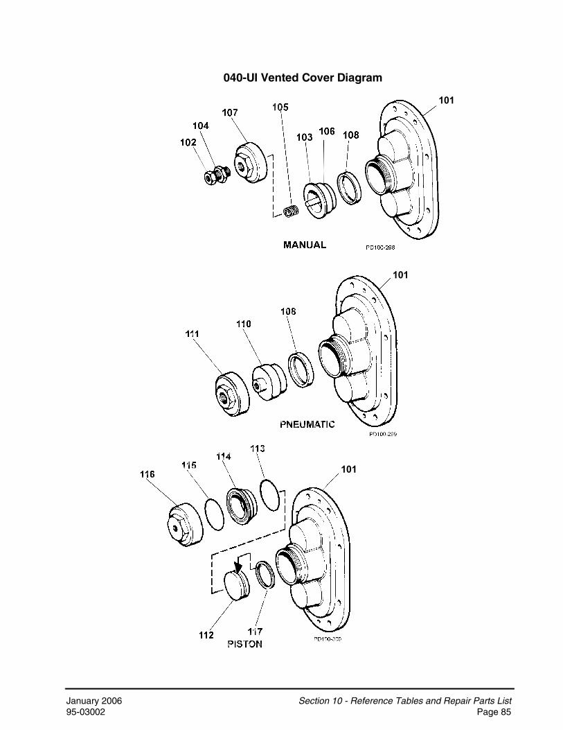
January 2006 Section 10 - Reference Tables and Repair Parts List95-03002 Page 85
040-UI Vented Cover Diagram
101
101
101

Section 10 - Reference Tables and Repair Parts List January 2006Page 86 95-03002
060-U1 Pump Body 1 See Note 1 1060-U1 Pump Body with Flush 1 See Note 1 1064-U1 Rectangular Flange Inlet Body 1 See Note 1 1064-U1 Rect. Flange Inlet Body with Flush 1 See Note 1 1130-U1 Pump Body 1 See Note 1 1130-U1 Pump Body with Flush 1 See Note 1 1134-U1 Rectangular Flange Inlet Body 1 See Note 1 1134-U1 Rect. Flange Inlet Body with Flush 1 See Note 1 1133-U1 Pump Body with Flush 1 133 001 020060-064-U1 Drive Shaft 1 060 008 001060-064-U1 Drive Shaft, Optional 17-4PH 1 35145130-134-U1 Drive Shaft 1 130 008 001130-134-U1 Drive Shaft, Optional 17-4PH 1 35394133-U1 Drive Shaft 1 133 008 001133-U1 Drive Shaft, Optional 17-4PH 1 34470060-064-U1 Short Shaft 1 060 009 001060-064-U1 Short Shaft, Optional 17-4PH 1 35146130-134-U1 Short Shaft 1 130 009 001130-134-U1 Short Shaft, Optional 17-4PH 1 35392133-U1 Short Shaft 1 133 009 001133-U1 Short Shaft, Optional 17-4PH 1 34471060-064-U1 Rotor, Twin Wing, Alloy 88 2 060 010 000 2060-064-U1 Rotor, Twin Wing, 316SS 2 060 010 200 2060-U1 Rotor, Single Wing, Alloy 88 2 117343 2, 12, 13130-134-U1 Rotor, Twin Wing, Alloy 88 2 130 010 000 2130-134-U1 Rotor, Twin Wing, 316SS 2 130 010 200 2130-U1 Rotor, Single Wing, Alloy 88 2 117360 2, 12A, 13133-U1 Rotor, Twin Wing, Alloy 88 2 133 010 020 2133-U1 Rotor, Single Wing, Alloy 88 2 117377 2, 12B
10A 060-U1 Stud 8 10884310B 060-U1 Stud, Jacketed Cover 8 10884610C 060-U1 Stud Retainer Assembly 1 070 064 000 5
064-U1 Stud 6 108843064-U1 Stud 2 0C1 050 000064-U1 Stud, Jacketed Cover 6 108846064-U1 Stud, Jacketed Cover 2 35556
10F 130-133-U1 Stud 8 130 011 00010G 130-U1 Stud, Jacketed Cover 8 130 011 00110H 130-133-U1 Stud Retainer Assembly 1 140 064 000 5
134-U1 Stud 6 130 011 000134-U1 Stud 2 0C1 050 000134-U1 Stud, Jacketed Cover 6 130 011 001134-U1 Stud, Jacketed Cover 2 35556
NOTES: 1. Contact Factory with Serial Number of pump for Part Number. 2. Standard clearances and finishes for Rotor Part Numbers shown. Contact Factory for optional clearances and finishes. 5. No longer manufactured, consult factory for upgrade of gear case subassembly. 12. Replaces 060 010 010 straight and 060 010 090 90° (degree) rotors. 12A. Replaces 130 010 010 straight and 130 010 090 90° (degree) rotors. 12B. Replaces 133 010 010 straight and 133 010 090 90° (degree) rotors. 13. Single wing rotors can not be used in Rectangular Flange Inlet pumps.
10E
10I
10J
7
8
9
10D
1
060 - 064 - 130 - 134 - 133-UI Pump Parts List
ITEM NO.
DESCRIPTIONQTY. PER
PUMP
PART NO.
NOTES

January 2006 Section 10 - Reference Tables and Repair Parts List95-03002 Page 87
060 - 064 - 130 - 134 - 133-UI Common Parts Diagram

Section 10 - Reference Tables and Repair Parts List January 2006Page 88 95-03002
060-064-130-134-U1 Pump Cover 1 CD0 002 S00060-064-130-134-U1 Jacketed Cover 1 CD0 002 J10133-U1 Pump Cover 1 133 002 020Pump Cover Vented - Complete Assembly060-064-130-134-U1 Manual (over 150 PSI) 1 CVR00036060-064-130-134-U1 Manual (under 150 PSI) 1 CVR00024060-064-130-134-U1 Pneumatic 1 CVR00053060-064-130-134-U1 Piston 1 CVR00054Gear Case, CI 1 070 005 000Gear Case, SS; Optional 1 101834Gear Case Cover, Steel 1 070 106 000Gear Case Cover, SS; Optional 1 102282
5 Gear, Drive Shaft, Spur 1 1074046 Gear, Short Shaft, Spur 1 107404
Wing Nut 8 105852Hex Nut, Optional 8 108371
12 Oil Seal, Gear Case Cover 1 000 030 01213 Oil Seal, Gear Case Rear 2 000 030 011
Grease Seal, Bearing Retainer 2 000 030 009Bearing Isolator Kit, Incl. STD Bearing Retainer 2 X06614-1Bearing Isolator Kit, Incl. SS Bearing Retainer 2 X06614-2
15 Bearing, Rear 2 10718616 Bearing, Front 2 060 036 00017 Key, Gear 2 060 037 00019 Drive Pin, Seal Seat and Sleeve 2 CD0 126 00020 Dowel Pin, Upper Cover Side 1 CD0 040 00021 Dowel Pin, Upper Gear Case Side 1 CD0 040 R0022 Dowel Pin, Lower Cover Side 1 CD0 040 10023 Dowel Pin, Lower Gear Case Side 1 CD0 040 R10
Plug w/ washer, 3/4-16 6 000 046 004 40Oil Plug, M20 x 1.5" 5 115798 41Oil Level Indicator, M20 x 1.5 1 115799 41
25 Silicone Sealant 1 000 142 30126 Jam Nut, Rotor 4 060 052 00127 Shim Kit 2 11789129 Spacer, Gear to Rear Bearing 2 10718730 Bearing Spacer 2 060 055 00331 Grease Retainer, Rear Bearing 2 STD 091 002
Bearing Retainer, Front 2 060 080 000Bearing Retainer, SS 2 1018123/8-16 x .75" HHCS, STD Gear Case Cover 6 30-3143/8-16 x .75" HHCS, SS Gear Case 6 30-503/8-16 x 1.25" HHCS, Brg. Ret., Std. Gear Case 8 30-3513/8-16 x 1.25" HHCS, Brg. Ret. SS Gear Case 8 30-60
33C 3/8" Flat Washer 6 43-189
NOTES: 40. For pumps prior to 5/15/03 41. For pumps after 5/15/03
060 - 064 -130 - 134 - 133-UI Common Parts List
ITEM NO.
DESCRIPTIONQTY.PER
PUMPPART NO. NOTES
33B
2
3
4
33A
32
11
14
24

January 2006 Section 10 - Reference Tables and Repair Parts List95-03002 Page 89
060 - 064 - 130 - 134 - 133-UI Common Parts Diagram

Section 10 - Reference Tables and Repair Parts List January 2006Page 90 95-03002
34 Dowel Bushing, Upper 1 CD0 116 00035 Dowel Bushing, Lower 1 CD0 116 100
* O-Ring, Pump Cover, Buna N 1 N70272* O-Ring, Pump Cover, EPDM 1 E70272* O-Ring, Pump Cover, FKM 1 V70272* O-Ring, Pump Cover, Silicone 1 S75272* 133-U1 O-Ring, Pump Cover, Inner, EPDM 1 133 117 002 11* 133-U1 O-Ring, Pump Cover, Inner, FKM 1 133 117 004 11* 133-U1 O-Ring, Pump Cover, Inner, Silicone 1 133 117 003 11* 064-U1 O-Ring, Rectangular Flange, Buna N 1 35360 14* 064-U1 O-Ring, Rectangular Flange, Buna N 1 N70366 14* 134-U1 O-Ring, Rectangular Flange, Buna N 1 N70272 14* 134-U1 O-Ring, Rectangular Flange, Buna N 1 N70369 14
37 Stop Pin, Seal 2 223 126 00039 Lockwasher, Gear 2 STD 136 00941 Locknut, Gear 2 STD 236 009
Gear Case Shim, CI 1 070 110 000Gear Case Shim, SS; Optional 1 102286Pump Pedestal, 5.5", Optional 1 CD0 110 SM5Pump Pedestal, 10", Optional 1 CD0 110 SM1
43 Plastic Cap Plug 8 000 121 00144 5/16-18 x 1" SHCS 4 30-275
060-064-U1 Body Retaining Screw, Optional 2 30-319 15130-133-134-U1 Body Retaining Screw, Optional 2 30-423 15
46 Eye Bolt 2 30-36047 Key, Coupling - 3/8 x 3/8 x 1-5/8" 1 000 037 00348 Cleanout Plug 2 41013
* 133-U1 O-Ring, Port, Inner, Silicone 2 S75041 11* 133-U1 O-Ring, Port, Inner, EPDM 2 E70041 11* 133-U1 O-Ring, Port, Outer, Silicone 2 S75043 11* 133-U1 O-Ring, Port, Outer, EPDM 2 E70043 11* 59 133-U1 3" 13I "I" Line Clamp 2 0345223 11* 60 133-U1 Aseptic Ferrule, 3" 2 133 267 000 11
61 Name Plate, Sanitary 1 001 061 00262 #2 x .125" RHDS 4 30-35563 O-Ring Removal Tool 1 AD0 096 001
Rotor Nut Wrench, SS 1 109897060-064-130-134-U1 Wrench, Jacketed Cover 1 060 019 001
65 Caution Plate 2 33-6266 Warning Label 2 33-60
060, 130, 133-U1 Grease Fitting, 1/8" 4 BD0 092 000064-134-U1 Grease Fitting, 1/8" 4 BD0 092 100
68 Plastic Cap, Grease Fitting 4 BD0 093 000
NOTES: 11. Used on 133-U1 only. 14. New O-Rings N70366 (064) and N70369 (134) introduced in 2001. Fits close to inlet opening. 15. New standard for Rectangular Flange Inlet pumps. Optional for standard inlet pumps. Body must be drilled at Factory to use. * Recommended Spare Parts
060 - 064 - 130 - 134 - 133-UI Common Parts List
36
42
ITEM NO.
DESCRIPTIONQTY. PER
PUMPPART NO. NOTES
67
36A
58
57
36B
45
64

January 2006 Section 10 - Reference Tables and Repair Parts List95-03002 Page 91
060 - 064 - 130 - 134 - 133-UI Common Parts Diagram

Section 10 - Reference Tables and Repair Parts List January 2006Page 92 95-03002
O-RING AND MECHANICAL SEAL PARTS* O-Ring, Body, Buna N 2 N70331 6, 25* O-Ring, Body, EPDM 2 E70331 6* O-Ring, Body, FKM 2 V70331 6* O-Ring, Body, Silicone 2 S75331 6* O-Ring, Shaft, Buna N 2 N70131 16, 25* O-Ring, Shaft, EPDM 2 E70131 16, 25* O-Ring, Shaft, FKM 2 V70131 16* O-Ring, Shaft, Silicone 2 S75131 16* Sleeve, SS 2 060 098 000* Sleeve, Zirconia 2 060 098 004* Sleeve, Chrome Oxide 2 060 098 002
84 O-Ring Seal Carrier 2 060 034 000 7* O-Ring, Outer, Buna N - Seal Carrier 2 N50338 7, 8* O-Ring, Outer, EPDM - Seal Carrier 2 E50338 7, 8* O-Ring, Outer, FKM - Seal Carrier 2 V50338 7, 8* 060-064-130-134-U1 Seal Seat, Ceramic 2 060 014 002* 060-064-130-134-U1 Seal Seat, Chrome Oxide 2 060 014 001* 060-064-130-134-U1 Seal Seat, Silicon Carbide 2 060 014 009* 133-U1 Seal Seat, Ceramic 2 133 014 002 11* 133-U1 Seal Seat, Chrome Oxide 2 133 014 001 11* 133-U1 Seal Seat, Silicon Carbide 2 133 014 009 11* Seal Inner, Carbon (2 Piece) 2 060 306 001* Seal Inner, Carbon (1 Piece) 2 060 306 007* Seal Inner, Ceramic 2 40642* Seal Inner, Chrome Oxide 2 060 306 002* Seal Inner, Silicon Carbide 2 060 306 009
88 Wave Spring 2 060 304 000* Outer Seal, Carbon (1 Piece) 2 060 206 007 8* Outer Seal, Chrome Oxide 2 060 206 002 8
NOTES: 6. (4) needed per pump with double O-ring Seal. 7. Used with double O-Ring Seal. 8. Used with double Mechanical Seal. 11. Used on 133-U1 only. 16. (4) needed per pump on 133-U1. 25. Sold in packages of 25 only. * Recommended Spare Parts
87
89
81
82
86
85
83
060 - 064 - 130 - 134 - 133-UI Seal Parts List
ITEM NO.
DESCRIPTIONQTY. PER
PUMP
PART NO.
NOTES

January 2006 Section 10 - Reference Tables and Repair Parts List95-03002 Page 93
060 - 064 - 130 - 134-UI Seal Parts Diagram
O-Ring Seal Mechanical Seal
133-U1 Aseptic Seal

Section 10 - Reference Tables and Repair Parts List January 2006Page 94 95-03002
MANUAL VENTED COVER101 Vented Cover 1 CD0 002 VS0102 Adjusting Screw 1 113657103 Spring Plunger 1 113397104 Locknut 1 GD0 074 000
Spring, Medium (less than 150 PSI) 1 113523Spring, High (more than 150 PSI) 1 113400
106 Diaphragm Bushing 1 CD0 077 000107 Cover Nut 1 113398
* 108 Rubber Diaphragm, Buna N 1 CD0 078 000PNEUMATIC VENTED COVER
101 Vented Cover 1 CD0 002 VS0* 108 Diaphragm, Buna N 1 CD0 078 000
110 Diaphragm Bushing 1 CD0 077 P00111 Cover Nut 1 CD0 075 P00
PISTON VENTED COVER101 Vented Cover 1 CD0 002 VS0112 Piston 1 CD0 073 P10
* 113 O-Ring, Bushing Seal, Buna N 1 N70239114 Diaphragm Bushing 1 CD0 077 P10
* 115 O-Ring, Nut Seal, Buna N 1 N70240116 Cover Nut 1 CD0 075 P10
* Piston Seal, Quad Ring 1 CD0 133 000 9* Piston Seal, O-Ring 1 N70236 9
NOTES: 9. Quad Ring and O-Ring can be interchanged. * Recommended Spare Parts
117
105
060 - 064 - 130 - 134-UI Vented Cover Parts List
ITEM NO.
DESCRIPTIONQTY. PER
PUMPPART NO. NOTES

January 2006 Section 10 - Reference Tables and Repair Parts List95-03002 Page 95
060 - 064 - 130 - 134-UI Vented Cover Diagram (Not Used on 133-UI Pump)
101
101

Section 10 - Reference Tables and Repair Parts List January 2006Page 96 95-03002
220-U1 Pump Body 1 See Note 1 1220-U1 Pump Body with Flush 1 See Note 1 1224-U1 Rectangular Flange Inlet Body 1 See Note 1 1224-U1 Rect. Flange Inlet Body with Flush 1 See Note 1 1223-U1 Pump Body 1 223 001 020220-224-U1 Drive Shaft, Std. 1 220 008 001220-224-U1 Drive Shaft, Optional 17-4PH 1 35349223-U1 Drive Shaft 1 223 008 001223-U1 Drive Shaft, Optional 17-4PH 1 35726220-224-U1 Short Shaft, Std. 1 220 009 001220-224-U1 Short Shaft, Optional 17-4PH 1 35350223-U1 Short Shaft 1 223 009 001223-U1 Short Shaft, Optional 17-4PH 1 35727220-224-U1 Rotor, Twin Wing, Alloy 88 2 220 010 000 2220-224-U1 Rotor, Twin Wing, 316SS 2 220 010 200 2220-224-U1 Rotor, Single Wing, Alloy 88 2 117391 2, 12, 13223-U1 Rotor, Twin Wing, Alloy 88 2 223 010 020 2
10A 220-U1 Stud 8 10884410B 220-U1 Stud, Jacketed Cover 8 108847
224-U1 Stud 6 108844224-U1 Stud 2 35550224-U1 Stud, Jacketed Cover 6 108847224-U1 Stud, Jacketed Cover 2 36144Stud Retainer Assembly 1 230 064 000 5
NOTES: 1. Contact Factory with Serial Number of pump for Part Number. 2. Standard clearance and finish Par Number shown. Contact Factory for optional clearances and finishes. 5. No longer manufactured, consult factory for upgrade of gear case subassembly. 12. Replaces 220 010 010 straight and 220 010 090 90° (degree) rotors. 13. Single wing rotors can not be used in Rectangular Flange Inlet pumps.
220 - 224 - 223-UI Pump Parts List
ITEM NO.
DESCRIPTIONQTY. PER
PUMP
PART NO.
NOTES
1
7
10C
10D
8
9

January 2006 Section 10 - Reference Tables and Repair Parts List95-03002 Page 97
220 - 224 - 223-UI Common Parts Diagram

Section 10 - Reference Tables and Repair Parts List January 2006Page 98 95-03002
220-224-U1 Pump Cover 1 GD0 002 S00 220-224-U1 Jacketed Cover 1 GD0 002 J10223-U1 Pump Cover 1 223 002 020Pump Cover Vented - Complete Assembly220-224-U1 Manual (over 150 PSI) 1 CVR00106220-224-U1 Manual (under 150 PSI) 1 CVR00009220-224-U1 Piston 1 CVR00008Gear Case, CI 1 230 005 000Gear Case, SS; Optional 1 101836Gear Case Cover, Steel 1 230 106 000Gear Case Cover, SS; Optional 1 102283
5 Gear, Drive Shaft, Spur 1 1109326 Gear, Short Shaft, Spur 1 110932
Wing Nut 8 105853Hex Nut, optional 8 108372
12 Oil Seal, Gear Case Cover 1 STD 030 00613 Oil Seal, Gear Case Rear 2 STD 119 002
Grease Seal, Bearing Retainer 2 STD 030 002Bearing Isolator, includes STD. Bearing Retainer 2 X06634-1Bearing Isolator, includes SS Bearing Retainer 2 X06634-2
15 Bearing, Rear 2 200 035 00016 Bearing, Front 2 200 036 00017 Key, Gear 2 200 037 00019 Drive Pin, Seal Seat and Sleeve 2 CD0 126 00020 Dowel Pin, Upper Cover Side 1 GD0 040 00021 Dowel Pin, Upper Gear Case Side 1 CD0 040 R0022 Dowel Pin, Lower Cover Side 1 GD0 040 10023 Dowel Pin, Lower Gear Case Side 1 CD0 040 R10
Plug w/ washer, 3/4-16 6 000 046 004 40Oil Plug, M20 x 1.5" 5 115798 41Oil Level Indicator, M20 x 1.5" 1 115799 41
25 Silicone Sealant 1 000 142 30126 Jam Nut, Rotor 4 GD0 052 00127 Shim Kit 2 11789229 Spacer, Gear to Rear Bearing 2 4087830 Bearing Spacer 2 40752
NOTES: 40. Pumps shipped prior to 5/15/03 41. Pumps shipped after 5/15/03
24
14
2
3
4
11
220 - 224 - 223-UI Common Parts List
ITEM NO.
DESCRIPTIONQTY. PER
PUMP
PART NO.
NOTES

January 2006 Section 10 - Reference Tables and Repair Parts List95-03002 Page 99
220 - 224 - 223-U1 Common Parts Diagram

Section 10 - Reference Tables and Repair Parts List January 2006Page 100 95-03002
Bearing Retainer, Front; STD. 2 220 080 000Bearing Retainer, Front; SS 2 1018133/8-16 x .75" HHCS, Std gear case 6 30-3143/8-16 x .75" HHCS, SS Gear case 6 30-503/8-16 x 1.25" SHCS, Brg Ret. Std gear case 8 30-3513/8-16 x 1.25" SHCS, Brg Ret., SS Gear case 8 30-60
33C 3/8" Flat Washer, Std gear case 6 43-18934 Dowel Bushing, Upper 1 CD0 116 00035 Dowel Bushing, Lower 1 CD0 116 100
* O-Ring, Pump Cover, Buna N 1 GD0 117 000* O-Ring, Pump Cover, EPDM 1 GD0 117 002* O-Ring, Pump Cover, FKM 1 GD0 117 V00* O-Ring, Pump Cover, Silicone 1 GD0 117 SC0* 223-U1 O-Ring, Pump Cover, Inner, EPDM 1 223 117 002 11* 223-U1 O-Ring, Pump Cover, Inner, FKM 1 V70278 11* 223-U1 O-Ring, Pump Cover, Inner, Silicone 1 223 117 003 11
224-U1 O-Ring, Rectangular Flange 1 GD0 117 000 12224-U1 O-Ring, Rectangular Flange 1 N70376 12
37 Stop Pin, Seal 2 223 126 00039 Lockwasher, Gear 2 STD 136 01141 Locknut, Gear 2 STD 236 011
Gear Case Shim, CI 1 230 110 000Gear Case Shim, SS 1 102287Pump Pedestal, 9" 1 GD0 110 SM9Pump Pedestal, 13" 1 GD0 110 SM1
43 Plastic Cap Plug 8 000 121 0011/2-13 x 2" SHCS, Std gear case 4 30-1111/2-13 x 2" SHCS, SS gear case 4 30-44
45 Body Retaining Screw, Optional 2 30-499 1546 1/2-13 Eye Bolt 2 30-36047 Key, Coupling - 1/2 x 1/2 x 1" 1 000 037 00448 Cleanout Plug 2 41013
* 57 223-U1 O-Ring, Port, Inner 2 E70154 11* 58 223-U1 O-Ring, Port, Outer 2 E70158 11* 59 223-U1 4" 13MHHMV "S" Clamp 2 119-87* 60 223-U1 Aseptic Ferrule, 4" 2 GGA 267 000
NOTES: 11. Used on 223-U1 only. 12. New O-Ring N70376 introduced in 2001. Fits close to inlet opening. 15. New standard for Rectangular Flange inlet pumps. Optional for standard inlet pumps. Body must be drilled at Factory. * Recommended Spare Parts
32
42
44
33B
33A
36B
36A
36
220 - 224 - 223-UI Common Parts List
ITEM NO.
DESCRIPTIONQTY. PER
PUMP
PART NO.
NOTES

January 2006 Section 10 - Reference Tables and Repair Parts List95-03002 Page 101
220 - 224 - 223-UI Common Parts Diagram

Section 10 - Reference Tables and Repair Parts List January 2006Page 102 95-03002
61 Name Plate, Sanitary 1 001 061 00262 #2 x .125" RHDS 4 30-35563 O-ring Removal Tool 1 AD0 096 001
Rotor Nut Wrench, SS 1 109898220-224-U1 Wrench, Jacketed Cover 1 AD0 019 001
65 Caution Plate 2 33-6266 Warning Label 2 33-60
220-223-U1 Grease Fitting, 1/8" 4 BD0 092 000224-U1 Grease Fitting, 1/8" 4 BD0 092 100
68 Plastic Cap, Grease Fitting 4 BD0 093 000
67
64
220 - 224 - 223-UI Common Parts List
ITEM NO.
DESCRIPTIONQTY. PER
PUMP
PART NO.
NOTES

January 2006 Section 10 - Reference Tables and Repair Parts List95-03002 Page 103
220 - 224 - 223-U1 Common Parts Diagram

Section 10 - Reference Tables and Repair Parts List January 2006Page 104 95-03002
O-RING AND MECHANICAL SEAL PARTS* O-Ring, Body, Buna N 2 N70338 6, 25* O-Ring, Body, EPDM 2 E70338 6* O-Ring, Body, FKM 2 V70338 6* O-Ring, Body, Silicone 2 S75338 6* O-Ring, Shaft, Buna N 2 N70144 16, 25* O-Ring, Shaft, EPDM 2 E70144 16* O-Ring, Shaft, FKM 2 V70144 16* O-Ring, Shaft, Silicone 2 S75144 16* Sleeve, SS 2 220 098 000* Sleeve, Zirconia 2 220 098 004* Sleeve, Chrome Oxide 2 220 098 002
84 O-Ring Seal Carrier 2 220 034 000 7* O-Ring, Outer, Buna N - Seal Carrier 2 N50344 7, 8* O-Ring, Outer, EPDM - Seal Carrier 2 E50344 7, 8* O-Ring, Outer, FKM - Seal Carrier 2 V50344 7, 8* O-Ring, Outer, Silicone - Seal Carrier 2 S50344 7, 8* 220-224-U1 Seal Seat, Ceramic 2 220 014 002* 220-224-U1 Seal Seat, Chrome Oxide 2 220 014 001* 220-224-U1 Seal Seat, Silicon Carbide 2 220 014 009* 223-U1 Seal Seat, Ceramic 2 223 014 002 11* 223-U1 Seal Seat, Chrome Oxide 2 223 014 001 11* 223-U1 Seal Seat, Silicon Carbide 2 223 014 009 11* Seal Inner, Carbon (2 piece) 2 220 306 001 * Seal Inner, Carbon (1 piece) 2 220 306 007* Seal Inner, Ceramic 2 40830* Seal Inner, Chrome Oxide 2 220 306 002* Seal Inner, Silicon Carbide 2 220 306 009
88 Wave Spring 2 220 304 000* Outer Seal, Carbon (1 piece) 2 220 206 007 8* Outer Seal, Chrome Oxide 2 220 206 002 8
NOTES: 6. (4) needed per pump with double O-ring Seal. 7. Used with double O-Ring Seal. 8. Used with double Mechanical Seal. 11. Used on 223-U1 only. 16. (4) needed on pump on 223-U1. 25. Sold in packages of 25 only. * Recommended Spare Parts
87
89
85
81
82
83
86
220 - 224 - 223-UI Seal Parts List
ITEM NO.
DESCRIPTIONQTY. PER
PUMP
PART NO.
NOTES

January 2006 Section 10 - Reference Tables and Repair Parts List95-03002 Page 105
220 - 224-U1 Seal Parts Diagram
O-Ring Seal Mechanical Seal
223-U1 Aseptic Seal

Section 10 - Reference Tables and Repair Parts List January 2006Page 106 95-03002
MANUAL VENTED COVER101 Vented Cover 1 GD0 002 VS0102 Adjusting Screw 1 113657103 Spring Plunger 1 GD0 073 000104 Locknut 1 GD0 074 000
Spring, Medium (less than 150 PSI) 1 113400Spring, High (more than 150 PSI) 1 113524
106 Diaphragm Bushing 1 GD0 077 000107 Cover Nut 1 GD0 075 000
* 108 Rubber Diaphragm, Buna N 1 GD0 078 000PISTON VENTED COVER
101 Vented Cover 1 GD0 002 VS0112 Piston 1 GD0 073 P10
* 113 O-Ring, Bushing Seal, Buna N 1 N70261114 Diaphragm Bushing 1 GD0 077 P10
* 115 O-Ring, Nut Seal, Buna N 1 N70261116 Cover Nut 1 GD0 075 P10
* Piston Seal, Quad Ring 1 GD0 133 000 9* Piston Seal, O-Ring 1 N70258 9
NOTES: 9. Quad Ring and O-Ring can be interchanged. * Recommended Spare Parts
117
ITEM NO.
DESCRIPTIONQTY. PER
PUMP
220 - 224-UI Vented Cover Parts List
PART NO.
NOTES
105

January 2006 Section 10 - Reference Tables and Repair Parts List95-03002 Page 107
220 - 224-U1 Vented Cover Diagram (Not Used on 223-U1 Pump)

Section 10 - Reference Tables and Repair Parts List January 2006Page 108 95-03002
320-U1 Pump Body 1 See Note 1 1324-U1 Rectangular Flange Inlet Body 1 See Note 1 1323-U1 Pump Body 1 323 001 020Drive Shaft, Std. OH1 008 002 3, 5Drive Shaft, Optional 17-4PH 33081 3, 5Drive Shaft Kit, Std. 1 113611 5ADrive Shaft Kit, Optional 17-4PH 1 113613 5ADrive Shaft, Std. 1 113518 4Drive Shaft, Optional 17-4PH 1 113520 4Short Shaft, Std. OH1 009 002 3, 5Short Shaft, Optional 17-4PH 33204 3, 5Short Shaft Kit, Std. 1 113612 5AShort Shaft Kit, Optional 17-4PH 1 113614 5AShort Shaft, Std. 1 113519 4Short Shaft, Optional 17-4PH 1 113521 4320-324-U1 Rotor, Twin Wing, Alloy 88 2 320 010 000 2320-324-U1 Rotor, Twin Wing, 316SS 2 320 010 200 2323-U1 Rotor, Twin Wing, Alloy 88 2 323 010 000 2320-323-U1 Stud, Cover, Long 4 111291 4
324-U1 Stud, Long 4 111291324-U1 Stud, Short 4 40699
10A Stud, Cover, Short 4 111292
NOTES: 1. Contact Factory with Serial Number of pump for Part Number. 2. Standard clearance and finish Par Number shown. Contact Factory for optional clearances and finishes. 3. Pumps shipped prior to July 30, 2001 4. Pumps shipped starting July 30, 2001. 5. No longer manufactured, See shaft kits 113611 and 113613, 113612 and 113614. 5A. Kits replace obsolete shafts OH1 008 002, 33081, OH1 009 002, and 33204 used in obsolete gear case OH1 005 000, which was supplied for pumps shipped prior to July 30, 2001.
Item no. Description Item no. Description5,6 Gears P/N 102470 17 Key, Gear P/N OH1 037 0007 Drive Shaft P/N 113518 or 113520 29 Spacer, Gear P/N 1176918 Short Shaft P/N 113519 or 113521 30 Spacer Front Bearing P/N 10247313 Oil Seal, Case Rear P/N STD 119 000 30A Bearing Spacer P/N 10247215 Bearing, Rear P/N OH1 036 000 31 Grease Retainer P/N STD 091 00016 Bearing, Front P/N OH1 036 003 41 Locknut, Gear P/N 105697
320 - 324 - 323-UI Pump Parts List
ITEM NO.
DESCRIPTIONQTY. PER
PUMP
PART NO.
NOTES
8
10
Kits 113611, 113612, 113613, and 113614 Include:
1
9
7

January 2006 Section 10 - Reference Tables and Repair Parts List95-03002 Page 109
320 - 324 - 323-UI Common Parts Diagram

Section 10 - Reference Tables and Repair Parts List January 2006Page 110 95-03002
320-324-U1 Pump Cover 1 OH1 002 002323-U1 Pump Cover 1 323 002 020Gear Case, CI 1 OH1 005 000 3, 5Gear Case, CI 1 40616 4
4 Gear Case Cover, Steel 1 406695 Gear, Drive Shaft, Spur 1 1024706 Gear, Short Shaft, Spur 1 102470
Wing Nut 8 110858Hex Nut, optional 8 108373
12 Oil Seal, Gear Case Cover 1 STD 030 004Oil Seal, Gear Case Rear 2 STD 119 000 3Oil Seal, Gear Case Rear 2 102475 4Grease Seal, Bearing Retainer 2 STD 030 002Bearing Isolator, includes STD. Bearing Retainer 2 X06634-3
15 Bearing, Rear 2 OH1 036 00016 Bearing, Front 2 OH1 036 00317 Key, Gear 2 OH1 037 00020 Dowel Pins 4 OH1 040 000
Plug w/ washer, 3/4-16 6 000 046 004 40Oil Plug, M20 x 1.5" 5 115798 41Oil Level Indicator, M20 x 1.5" 1 115799 41
25 Silicone Sealant 1 000 142 30126 Jam Nut, Rotor 4 OH1 052 00327 Shim Kit 2 117893
Spacer, Gear to Rear Bearing 2 117691 3Spacer, Gear to Rear Bearing 2 102474 4
30 Bearing Spacer 2 102473 430A Spacer Front Bearing 2 102472 431 Grease Retainer, Rear Bearing 2 STD 091 00032 Bearing Retainer, Front 2 OH1 080 000
33A 3/8-16 x .75" HHCS, Gear Case cover 6 30-31433B 5/16-18 x 1" SHCS, Bearing Retainer 8 30-34333C 3/8" Washer, Plain 6 43-18934 Dowel Bushings 2 OH1 116 000
NOTES: 3. Pumps shipped prior to July 30, 2001 4. Pumps shipped starting July 30, 2001. 5. No longer manufactured, consult factory for upgrade of gear case subassembly. 40. Pumps shipped prior to 5/15/03 41. Pumps shipped after 5/15/03
29
13
14
2
11
3
24
NOTES
320 - 324 - 323-UI Common Parts List
ITEM NO.
DESCRIPTIONQTY. PER
PUMP
PART NO.

January 2006 Section 10 - Reference Tables and Repair Parts List95-03002 Page 111
320 - 324 - 323-UI Common Parts Diagram

Section 10 - Reference Tables and Repair Parts List January 2006Page 112 95-03002
* O-Ring, Pump Cover, Buna N 1 N70280* O-Ring, Pump Cover, EPDM 1 E70280* O-Ring, Pump Cover, FKM 1 V70280* O-Ring, Pump Cover, Silicone 1 323 117 013* 323-U1 O-Ring, Pump Cover, Inner, EPDM 1 323 117 002 11* 323-U1 O-Ring, Pump Cover, Inner, FKM 1 323 117 004 11* 323-U1 O-Ring, Pump Cover, Inner, Silicone 1 323 117 003 11
36B 324-U1 O-Ring, Rectangular Flange 1 N7038241 Locknut, Gear 2 105697
Gear Case Shim, CI 1 40288Pump Pedestal, 22" 1 324 110 226
43 Plastic Cap Plug 6 000 121 00144 1/2-13 x 1.75" SHCS 4 30-250
44A Lockwasher, 1/2" 4 43-17745 Body Retaining, 3/8-16 x 4" SHCS 2 30-32346 1/2-13 Eye Bolt 3 30-36047 Key, Coupling - 5/8 x 5/8 x 2" 1 000 037 00548 Cleanout Plug 2 4101350 Grease Retainer, Gear Case, Front Bearing 2 STD 030 003 352 Spacer, Rear Bearing 2 OH1 055 002 353 Locknut, Front Bearing 2 OH1 236 001 354 Lockwasher, Front Bearing 2 OH1 136 001 355 Spacer, Front Bearing 2 OH1 055 001 356 Guard, Seal 2 113505
* O-Ring, Port, Inner, Silicone 2 S75261 11* O-Ring, Port, Inner, EPDM 2 E70261 11* O-Ring, Port, Inner, FKM 2 V70261 11* O-Ring, Port, Outer, Silicone 2 S75265 11* O-Ring, Port, Outer, EPDM 2 E70265 11* O-Ring, Port, Outer, FKM 2 V70265 11
61 Name Plate 1 001 061 01562 #2 x .125" RHDS 4 30-35563 O-ring Removal Tool 1 AD0 096 00164 Rotor Nut Wrench, SS 1 11282965 Caution Plate 2 33-6266 Warning Label 2 33-60
320-323-U1 Grease Fitting, 1/8" 4 BD0 092 000324-U1 Grease Fitting, 1/8" 4 BD0 092 100
68 Plastic Cap, Grease Fitting 4 BD0 093 000
NOTES: 3. Pumps shipped prior to July 30, 2001 4. Pumps shipped starting July 30, 2001. 11. Used on 323-U1 only. * Recommended Spare Parts
36
42
36A
67
57
58
320 - 324 - 323-UI Common Parts List
ITEM NO.
DESCRIPTIONQTY. PER
PUMP
PART NO.
NOTES

January 2006 Section 10 - Reference Tables and Repair Parts List95-03002 Page 113
320 - 324 - 323-UI Common Parts Diagram

Section 10 - Reference Tables and Repair Parts List January 2006Page 114 95-03002
MECHANICAL SEAL PARTSOUTER SEAL
* 70 Crane #8B2 Outer Seal, Carbon 2 323 114 003 30* O-Ring, Outer Seal, Shaft, EPDM 2 E70234* O-Ring, Outer Seal, Shaft, FKM 2 V70234* O-Ring, Outer Seal, Shaft, Silicone 2 S75234* "T" Seat, Plain, Ceramic 2 300 014 012* "T" Seat, Plain, Tungsten Carbide 2 300 014 013* "T" Seat, Plain, Silicon Carbide 2 300 014 016* 72B, 72C Gasket, Inner and Outer 4 300 042 001
73 Gland, Plain 2 300 034 001 73B 3/8-16 x 1-1/4" HHCS 8 30-6073C Lockwasher, 3/8" 8 43-28
INNER SEAL* Waukesha HD Inner Seal, Silicon Carbide 2 40572 16* Waukesha HD Inner Seal, Ceramic 2 40573 16* Waukesha HD Inner Seal, Chrome Oxide 2 40574 16* Seal Face, Silicon Carbide 2 40754* Seal Face, Ceramic 2 40755* Seal Face, Chrome Oxide 2 40756* Seal Face, Tungsten Carbide 2 109347* Seal Face, Carbon 2 36027* O-Ring, Inner Seal, Shaft, EPDM 2 E70234* O-Ring, Inner Seal, Shaft, FKM 2 V70234* O-Ring, Inner Seal, Shaft, Silicone 2 S75234* 71D Spring 12 40875* 71F Set Screw 8 110038* O-Ring, Inner Seal, Seal Face, EPDM 2 E70238 * O-Ring, Inner Seal, Seal Face, FKM 2 V70238 * O-Ring, Inner Seal, Seal Face, Silicone 2 S75238
INNER - OUTER SEAL71C Carrier Inner Sub-Assembly 1 35284
* "T" Seat, Flushed, Ceramic 2 300 014 027* "T" Seat, Flushed, Tungsten Carbide 2 300 014 028* "T" Seat, Flushed, Chrome Oxide 2 300 014 029* "T" Seat, Flushed, Silicon Carbide 2 300 014 031* 72B Gasket, Inner 2 300 042 001* 72C Gasket, Flushed Gland, Outer 2 300 042 002
73A Gland, Flushed 2 300 034 00173B 3/8-16 x 1-1/4" HHCS 8 30-6073C 3/8" Lockwasher 8 43-28
NOTES: 16. Complete Inner Seal with FKM O-Rings. 30. Alternate materials available. Standard is listed. Contact factory for information. * Recommended Spare Parts
71B
71H
72A
70B
72
71
71A
320 - 324 - 323-UI Seal Parts List
ITEM NO.
DESCRIPTIONQTY. PER
PUMP
PART NO.
NOTES

January 2006 Section 10 - Reference Tables and Repair Parts List95-03002 Page 115
320 - 324 - 323-UI Seals Parts Diagram
320 - 324 - 323-U1 Inner-Outer Seal
320 - 324-U1 Outer Seal

Section 10 - Reference Tables and Repair Parts List January 2006Page 116 95-03002
Universal I PD Pump Dimensions - Rectangular Flange with Pedestal

January 2006 Section 10 - Reference Tables and Repair Parts List95-03002 Page 117
Universal I PD Pump Dimensions - Rectangular Flange with Pedestal

Section 10 - Reference Tables and Repair Parts List January 2006Page 118 95-03002
Tru-Fit™ Universal I PD Pump Dimensions
Tru-Fit™
Universal I Pump Size
A B B/2 C D2 E F G H J K
inch 12.0 10.0 5.0 9.15 6.97 7.87 13.25 2.01 18.0 2.43 10.08mm 305 254 127 232 177 200 337 51 457 62 256inch 12.0 10.0 5.0 9.15 6.97 7.87 13.25 2.01 18.0 2.43 10.08mm 304 254 127 232 177 200 337 51 457 62 256inch 12.0 10.0 5.0 9.15 7.10 7.87 13.25 2.25 18.0 2.62 10.31mm 304 254 127 232 180 200 337 57 457 67 262inch 14.0 12.0 6.0 10.02 8.51 8.37 15.11 2.59 20.0 2.97 12.47mm 356 304 152 255 216 213 384 66 508 75 317inch 14.0 12.0 6.0 10.02 8.62 8.37 15.11 2.97 20.0 2.97 12.84mm 356 305 152 255 219 213 384 75 508 75 326inch 18.0 16.0 8.0 12.0 10.74 9.75 20.0 3.01 28.0 3.77 17.39mm 457 406 203 305 273 248 508 76 711 96 442inch 18.0 16.0 8.0 12.0 10.74 9.75 20.0 3.64 28.0 4.08 18.02mm 457 406 203 305 273 248 508 92 711 104 458inch 20.0 18.0 9.0 14.5 13.25 11.5 23.25 3.51 36.0 4.99 19.76mm 508 457 229 368 337 292 591 89 914 127 502
Tru-Fit™
Universal I Pump Size
L M1 N1 P1 R S T V
inch 12.51 27.60 15.56 10.92 2.79 5.44 2.12 2.00mm 318 701 395 227 71 138 54 51inch 12.51 27.60 15.56 10.92 2.79 5.44 2.12 2.00mm 318 701 395 227 71 138 54 51inch 12.93 28.02 15.56 10.92 3.02 5.44 2.12 2.00mm 328 712 395 227 77 138 54 51inch 15.44 33.67 18.65 13.74 3.84 5.81 2.62 2.25mm 392 855 474 349 98 148 67 57inch 15.81 34.04 18.65 13.74 4.22 5.81 2.62 2.25mm 402 865 474 349 107 148 67 57inch 21.16 43.77 22.02 17.16 5.01 8.13 3.50 3.50mm 537 1112 559 436 127 207 89 89inch 22.10 44.71 22.02 17.16 5.65 8.13 3.50 3.50mm 561 1136 559 436 144 207 89 89inch 24.51 52.23 25.91 18.82 4.73 10.00 4.50 5.38mm 623 1327 658 478 120 254 114 137
PD100-4371 Dimensions affected by Motor Frame Size.2 Dimensions affected by Connection Type.
130
N/A5/16-18 x .62
N/A
006
015
018
030
220
040
060
3/8-16 x .62N/A
3/8-16 x .62N/A
220
1/2-13 x .88N/A
1/2-13 x .88N/A
030
040
060
130
1/2-13 x 1.0N/A
U
5/16-18 x .62N/A
5/16-18 x .62
006
015
018

January 2006 Section 10 - Reference Tables and Repair Parts List95-03002 Page 119
Tru-Fit™ Universal I PD Pump Dimensions - Ductile Iron Base

Section 10 - Reference Tables and Repair Parts List January 2006Page 120 95-03002
Tru-Fit™
Universal I Pump Size
A B B/2 C D2 E F G H J K
inch 12.0 10.0 5.0 9.15 6.97 7.87 13.25 2.01 18.0 2.43 10.08mm 305 254 127 232 177 200 337 51 457 62 256inch 12.0 10.0 5.0 9.15 6.97 7.87 13.25 2.01 18.0 2.43 10.08mm 304 254 127 232 177 200 337 51 457 62 256inch 12.0 10.0 5.0 9.15 7.10 7.87 13.25 2.25 18.0 2.62 10.31mm 304 254 127 232 180 200 337 57 457 67 262inch 14.0 12.0 6.0 10.02 8.51 8.37 15.11 2.59 20.0 2.97 12.47mm 356 304 152 255 216 213 384 66 508 75 317inch 14.0 12.0 6.0 10.02 8.62 8.37 15.11 2.97 20.0 2.97 12.84mm 356 305 152 255 219 213 384 75 508 75 326inch 18.0 16.0 8.0 12.0 10.74 9.75 20.0 3.01 28.0 3.77 17.39mm 457 406 203 305 273 248 508 76 711 96 442inch 18.0 16.0 8.0 12.0 10.74 9.75 20.0 3.64 28.0 4.08 18.02mm 457 406 203 305 273 248 508 92 711 104 458inch 20.0 18.0 9.0 14.5 13.25 11.5 23.25 3.51 36.0 4.99 19.76mm 508 457 229 368 337 292 591 89 914 127 502
Tru-Fit™
Universal I Pump Size
L M1 N1 P1 R S T V
inch 12.51 27.60 15.56 10.92 2.79 5.44 2.12 2.00mm 318 701 395 227 71 138 54 51inch 12.51 27.60 15.56 10.92 2.79 5.44 2.12 2.00mm 318 701 395 227 71 138 54 51inch 12.93 28.02 15.56 10.92 3.02 5.44 2.12 2.00mm 328 712 395 227 77 138 54 51inch 15.44 33.67 18.65 13.74 3.84 5.81 2.62 2.25mm 392 855 474 349 98 148 67 57inch 15.81 34.04 18.65 13.74 4.22 5.81 2.62 2.25mm 402 865 474 349 107 148 67 57inch 21.16 43.77 22.02 17.16 5.01 8.13 3.50 3.50mm 537 1112 559 436 127 207 89 89inch 22.10 44.71 22.02 17.16 5.65 8.13 3.50 3.50mm 561 1136 559 436 144 207 89 89inch 24.51 52.23 25.91 18.82 4.73 10.00 4.50 5.38mm 623 1327 658 478 120 254 114 137
PD100-4371 Dimensions affected by Motor Frame Size.2 Dimensions affected by Connection Type.
130
N/A5/16-18 x .62
N/A
006
015
018
030
220
040
060
3/8-16 x .62N/A
3/8-16 x .62N/A
220
1/2-13 x .88N/A
1/2-13 x .88N/A
030
040
060
130
1/2-13 x 1.0N/A
U
5/16-18 x .62N/A
5/16-18 x .62
006
015
018
Tru-Fit™ Universal I PD Pump Dimensions

January 2006 Section 10 - Reference Tables and Repair Parts List95-03002 Page 121
Tru-Fit™ Universal I PD Pump Dimensions - Stainless Steel Base

Section 10 - Reference Tables and Repair Parts List January 2006Page 122 95-03002
Tru-Fit™ Universal I PD Pumps Parts List
006, 014, 015 018, 024 030, 034 0403 Gear Case, CI 118986 118986 121687 121687
4A Gear Case Cover, Adapter 118982 118982 118678 1186787 Drive Shaft 119174 119175 119176 119177
1/4-20 x 1" HHCS 30-93 30-935/16-18 x 1-1/8" HHCS 30-237 30-2375/16" x 3/4" lg. SHSB 30-690 30-6903/8" x 3/4" lg. SHSB 30-691 30-691Flat Washer, 5/16" 43-246 43-246Flat Washer, 3/8" 43-30 43-30
060, 064 130, 134 220, 224 320, 3243 Gear Case, CI 118987 118987 118988 118989
4A Gear Case Cover, Adapter (Serial # Req'd) (Serial # Req'd) (Serial # Req'd) (Serial # Req'd)
7 Drive Shaft 119178 119179 119180 1191813/8-16 x 1-1/2" HHCS 30-50 30-50 30-501/2-13 x 1-1/2" HHCS 30-1031/2" x 1" lg. SHSB 30-692 30-692 30-6925/8" x 1" lg. SHSB 30-693
44A Flat Washer, 1/2" 43-31 43-31 43-31 43-31PD100-434a
44A
Item # Part Description
33D
33E
33D
Part DescriptionItem #
Universal I Pump Size
Universal I Pump Size
33E

January 2006 Section 10 - Reference Tables and Repair Parts List95-03002 Page 123
Tru-Fit™ Universal I PD Pumps Diagram

Section 10 - Reference Tables and Repair Parts List January 2006Page 124 95-03002
New Part Numbers for Pumps Sold After 7/12/04
UI Model Number DescriptionPart # before 7/12/04 (OLD)
Part # after 7/12/04 (NEW)
006, 014, 015, 018, 024Grease Seal, Bearing Retainer 101716 121679Bearing Retainer, Front 101810 120332O-Ring Seal Carrier 015034000 015034001
030, 034, 040Grease Seal, Bearing Retainer 101717 121680Bearing Retainer, Front 101811 120333O-Ring Seal Carrier 030034000 030034001
060, 064, 130, 134Bearing Retainer, Front STD 060080000 123531Bearing Retainer, Front SS 101812 121828O-Ring Seal Carrier 060034000 060034001
220, 224Grease Seal, Bearing Retainer STD030002 121681Bearing Retainer, Front STD 220080000 123532Bearing Retainer, Front SS 101813 121829O-Ring Seal Carrier 220034000 220034001
320, 324Grease Seal, Bearing Retainer STD030002 121681Bearing Retainer, Front STD 0H1080000 123533Bearing Retainer, Front SS 118365 123533
PD100-441


611 Sugar Creek Road • Delavan, WI 53115 USATel: (800) 252-5200 or (262) 728-1900 • Fax: (800) 252-5012 or (262) 728-4904
E-mail: [email protected] • Web site: www.spxprocessequipment.comRevised: January 2006
95-03002