operation and maintenance manual scraped surface heat ... · pdf fileoperation and maintenance...
TRANSCRIPT

Operation and Maintenance ManualScraped Surface Heat Exchanger
Read and understand this manualprior to installing, operating or servicing this equipment.

611 Sugar Creek RoadDelavan, WI 53115 USA
Tel: (800) 252-5200 or (262) 728-1900Fax: (800) 252-5012 or (262) 728-4904
E-mail: [email protected] site: www.spxprocessequipment.com
Information contained in this manual is subject to changewithout notice and does not represent a commitment onthe part of Waukesha Cherry-Burrell. No part of thismanual may be reproduced or transmitted in any form orby any means, electronic or mechanical, includingphotocopying and recording, for any purpose, without theexpress written permission of Waukesha Cherry-Burrell.
Copyright © 2004 All Rights Reserved.
Issued Date: October 2005
Publication: 95-03057

Table of Contents
October 2005 95-03057 Page 3
Waukesha Cherry-Burrell Warranty .........................................................7Shipping Damage or Loss .............................................................................7Warranty Claim .............................................................................................7
Safety ..............................................................................................................8Care of Stainless Steel ..................................................................................9
Stainless Steel Corrosion ..............................................................................9Elastomer Seal Replacement Following Passivation ....................................9
Introduction ..................................................................................................10Models and Specifications ............................................................................10Cylinder Assembly .......................................................................................10Product Side Pressure Rating ........................................................................10Jacket Pressure Rating ..................................................................................10Machine Serial Number ................................................................................10Votator II Media Configurations ..................................................................10Special Considerations for Vertical Votator II .............................................10
Installation .....................................................................................................11Site Selection Considerations .......................................................................11
Foundation & Drainage .............................................................................. 11Clearances .....................................................................................................11Leveling the Unit ..........................................................................................11Electrical Power Connections .......................................................................11Mutator Rotation Check ................................................................................11Mechanical Seals ..........................................................................................12
Single Mechanical Seal .............................................................................. 12Double Mechanical Seal ............................................................................. 122005 Mechanical Seal Design .................................................................... 12Flush Water Requirements ......................................................................... 13
Piping ............................................................................................................13Guidelines for Piping .................................................................................. 13
Suggested Media Piping for Water or Liquid ...............................................15Refrigeration Piping Installation ...................................................................16
Liquid Line Installation .............................................................................. 16Suction Line Installation ............................................................................ 16Hot Gas Line (if required) .......................................................................... 16Pressure Relief Line ................................................................................... 16
Refrigeration Valves .....................................................................................17Liquid Feed Solenoid Valve ....................................................................... 17Dual Pressure Regulating Valve ................................................................. 17Sporlan Level Master Control (LMC) or Level Switch ............................. 17Refrigerant Return Valve ........................................................................... 17Flow Control Valves .................................................................................. 17Hot Gas Pressure Regulating Valve ........................................................... 17Pressure Relief Valve ................................................................................. 17
Suggested Media Piping for Liquid Over Feed Refrigeration ......................18Suggested Media Piping for Gravity Refrigeration ......................................19Electrical Equipment .....................................................................................21Refrigeration Wiring Schematics ..................................................................22

Table of Contents
Page 4 95-03057 October 2005
Freeze Protection Components .................................................................. 22Gravity Refrigeration with Level Master Control (LMC) ......................... 23Gravity Refrigeration with Level Switch ................................................... 24Liquid Overfeed Refrigeration System ...................................................... 25
Media System Check ....................................................................................26Special Considerations for Vertical Votator II .............................................26Minimum Height - Vertical Votator II .........................................................26Mounting Pole - Vertical Votator II .............................................................26Mounting Scrape Cylinders - Vertical Votator II .........................................26Hydraulic System - Vertical Votator II .........................................................27
Check and Adjust Hydraulic Cylinder ....................................................... 27Fill Hydraulic Reservoir ............................................................................ 27Check Balance and Pressure Settings ........................................................ 27
Gravity Refrigeration System - Vertical Votator II ......................................28Operation ...................................................................................................... 29
Pre-Startup Check .........................................................................................29For Refrigeration Units Only ..................................................................... 29
Pre-production Run Setup .............................................................................29Startup Procedure ..........................................................................................29
Heating/Liquid Cooling Applications ........................................................ 29Refrigeration Applications - Pumped and Gravity Systems ...................... 30PLC Maintenance Setup and Startup Procedures for Refrigeration .......... 30Refrigeration Applications - Pumped and Gravity Systems - PLC Panel . 31
Refrigeration Sequence of Operation ...........................................................35Liquid Overfeed System ............................................................................ 35Gravity Systems ......................................................................................... 35
Refrigeration Sequence of Operation - PLC Control Panel ..........................36Liquid Overfeed System ............................................................................ 36Gravity Systems ......................................................................................... 36
Shutdown Procedure .....................................................................................37Preventing Tube Scoring ..............................................................................37
Maintenance .................................................................................................. 38Routine Maintenance Checklist - Vertical Votator II ...................................38Routine Maintenance Checklist - Horizontal Votator II ...............................39Scheduled Maintenance ................................................................................40Preventive Maintenance ................................................................................41Mutator Shaft Bearing ..................................................................................41
Extra Heavy Duty Votator II Shaft Bearing .............................................. 41Shafts ............................................................................................................41Gear Drive .....................................................................................................41Blades ............................................................................................................41Mechanical Seals ..........................................................................................42Tubes .............................................................................................................42Care of Heat Exchanger Tube .......................................................................42Product Side ..................................................................................................42Inspection of Chrome Plated Nickel or Stainless Steel Tubes ......................43Inspection of Stainless Steel Tubes ..............................................................43
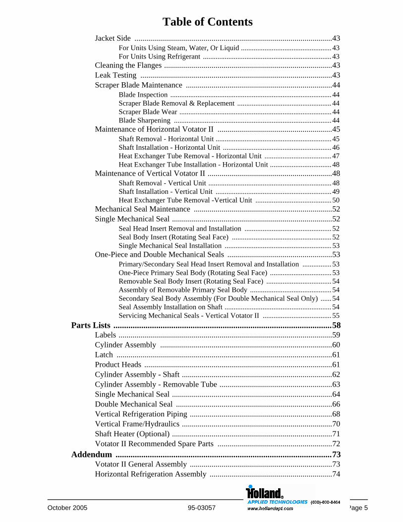
Table of Contents
October 2005 95-03057 Page 5
Jacket Side ....................................................................................................43For Units Using Steam, Water, Or Liquid .................................................. 43For Units Using Refrigerant ....................................................................... 43
Cleaning the Flanges .....................................................................................43Leak Testing .................................................................................................43Scraper Blade Maintenance ..........................................................................44
Blade Inspection ......................................................................................... 44Scraper Blade Removal & Replacement .................................................... 44Scraper Blade Wear .................................................................................... 44Blade Sharpening ....................................................................................... 44
Maintenance of Horizontal Votator II ..........................................................45Shaft Removal - Horizontal Unit ................................................................ 45Shaft Installation - Horizontal Unit ............................................................ 46Heat Exchanger Tube Removal - Horizontal Unit ..................................... 47Heat Exchanger Tube Installation - Horizontal Unit .................................. 48
Maintenance of Vertical Votator II ...............................................................48Shaft Removal - Vertical Unit .................................................................... 48Shaft Installation - Vertical Unit ................................................................ 49Heat Exchanger Tube Removal -Vertical Unit .......................................... 50
Mechanical Seal Maintenance ......................................................................52Single Mechanical Seal .................................................................................52
Seal Head Insert Removal and Installation ................................................ 52Seal Body Insert (Rotating Seal Face) ....................................................... 52Single Mechanical Seal Installation ........................................................... 53
One-Piece and Double Mechanical Seals .....................................................53Primary/Secondary Seal Head Insert Removal and Installation ................ 53One-Piece Primary Seal Body (Rotating Seal Face) .................................. 53Removable Seal Body Insert (Rotating Seal Face) .................................... 54Assembly of Removable Primary Seal Body ............................................. 54Secondary Seal Body Assembly (For Double Mechanical Seal Only) ...... 54Seal Assembly Installation on Shaft ........................................................... 54Servicing Mechanical Seals - Vertical Votator II ...................................... 55
Parts Lists ......................................................................................................58Labels ............................................................................................................59Cylinder Assembly .......................................................................................60Latch .............................................................................................................61Product Heads ...............................................................................................61Cylinder Assembly - Shaft ............................................................................62Cylinder Assembly - Removable Tube .........................................................63Single Mechanical Seal .................................................................................64Double Mechanical Seal ...............................................................................66Vertical Refrigeration Piping ........................................................................68Vertical Frame/Hydraulics ............................................................................70Shaft Heater (Optional) .................................................................................71Votator II Recommended Spare Parts ..........................................................72
Addendum .....................................................................................................73Votator II General Assembly ........................................................................73Horizontal Refrigeration Assembly ..............................................................74

Table of Contents
Page 6 95-03057 October 2005
Vertical Refrigeration System ......................................................................75Horizontal Frame Options ............................................................................76Vertical Mounting Pole/Hydraulics ..............................................................77Vertical Hydraulic Schematic .......................................................................78
Troubleshooting Chart ................................................................................ 79Unthawing A Frozen System ........................................................................82Water and Air in Refrigeration System ........................................................82

Waukesha Cherry-Burrell Warranty
October 2005 95-03057 Page 7
Waukesha Cherry-Burrell Warranty
Seller warrants its products to be free from defect in materials and workmanship for a period of one (1) year from the dateof shipment. This warranty shall not apply to products which require repair or replacement due to normal wear and tear orto products which are subjected to accident, misuse or improper maintenance. This warranty extends only to the originalBuyer. Products manufactured by others but furnished by Seller are exempted from this warranty and are limited to theoriginal manufacturer’s warranty.
Seller’s sole obligation under this warranty shall be to repair or replace any products that Seller determines, in itsdiscretion, to be defective. Seller reserves the right either to inspect the products in the field or to request their prepaidreturn to Seller. Seller shall not be responsible for any transportation charges, duty, taxes, freight, labor or other costs. Thecost of removing and/or installing products which have been repaired or replaced shall be at Buyer’s expense.
Seller expressly disclaims all other warranties, express or implied, including without limitation any warranty ofmerchantability of fitness for a particular purpose. The foregoing sets forth Seller’s entire and exclusive liability, andBuyer’s exclusive and sole remedy, for any claim of damages in connection with the sale of products. In no event shallSeller be liable for any special consequential incidental or indirect damages (including without limitation attorney’s feesand expenses), nor shall Seller be liable for any loss of profit or material arising out of or relating to the sale or operationof the products based on contract, tort (including negligence), strict liability or otherwise.
Shipping Damage or Loss
If equipment is damaged or lost in transit, file a claim at once with the delivering carrier. The carrier has signed the Bill ofLading acknowledging that the shipment has been received from WCB in good condition. WCB is not responsible for thecollection of claims or replacement of materials due to transit shortages or damages.
Warranty Claim
Warranty claims must have a Returned Goods Authorization (RGA) from the Seller before returns will be accepted.
Claims for shortages or other errors, exclusive of transit shortages or damages, must be made in writing to Seller withinten (10) days after delivery. Failure to give such notice shall constitute acceptance and waiver of all such claims by Buyer.

Safety Waukesha Cherry-Burrell
Page 8 95-03057 October 2005
SafetyREAD AND UNDERSTAND THIS MANUAL
PRIOR TO INSTALLING, OPERATING OR SERVICING THIS EQUIPMENT
Waukesha Cherry-Burrell recommends users of our equipment and designs follow the latest Industrial Safety Standards.At a minimum, these should include the industrial safety requirements established by:
1. Occupational Safety and Health Administration (OSHA), Title 29 of the CFRSection 1910.212- General Requirements for all Machines
2. National Fire Protection Association, ANSI/NFPA 79ANSI/NFPA 79- Electrical Standards for Industrial Machinery
3. National Electrical Code, ANSI/NFPA 70ANSI/NFPA 70- National Electrical CodeANSI/NFPA 70E- Electrical Safety Requirement for Employee Workplaces
4. American National Standards Institute, Section B11
Attention: Servicing energized industrial equipment can be hazardous. Severe injury or death can result from electricalshock, burn, or unintended actuation of controlled equipment. Recommended practice is to disconnect and lockoutindustrial equipment from power sources, and release stored energy, if present. Refer to the National Fire ProtectionAssociation Standard No. NFPA70E, Part II and (as applicable) OSHA rules for Control of Hazardous Energy Sources(Lockout-Tagout) and OSHA Electrical Safety Related Work Practices, including procedural requirements for:
• Lockout-tagout
• Personnel qualifications and training requirements
• When it is not feasible to de-energize and lockout-tagout electrical circuits and equipment before working on or nearexposed circuit parts
Locking and Interlocking Devices: These devices should be checked for proper working condition and capability ofperforming their intended functions. Make replacements only with the original manufacturer’s renewal parts or kits.Adjust or repair in accordance with the manufacturer’s instructions.
Periodic Inspection: Industrial equipment should be inspected periodically. Inspection intervals should be based onenvironmental and operating conditions and adjusted as indicated by experience. At a minimum, an initial inspectionwithin 3 to 4 months after installation is recommended. Inspection of the electrical control systems should meet therecommendations as specified in the National Electrical Manufacturers Association (NEMA) Standard No. ICS 1.3,Preventative Maintenance of Industrial Control and Systems Equipment, for the general guidelines for setting-up aperiodic maintenance program.
Replacement Equipment: Use only replacement parts and devices recommended by the manufacturer to maintain theintegrity of the equipment. Make sure the parts are properly matched to the equipment series, model, serial number, andrevision level of the equipment.
Warnings and cautions are provided in this manual to help avoid serious injury and/or possible damage to equipment:
DANGER: marked with a stop sign.Immediate hazards which WILL result in severe personal injury or death.
WARNING: marked with a warning triangle.Hazards or unsafe practices which COULD result in severe personal injury or death.
CAUTION: marked with a warning triangle.Hazards or unsafe practices which COULD result in minor personal injury or product or property damage.

Waukesha Cherry-Burrell Care of Stainless Steel
October 2005 95-03057 Page 9
Care of Stainless Steel
Stainless Steel Corrosion
Corrosion resistance is greatest when a layer of oxide film is formed on the surface of stainless steel. If film is disturbed ordestroyed, stainless steel becomes much less resistant to corrosion and may rust, pit or crack.
Corrosion pitting, rusting and stress cracks may occur due to chemical attack. Use only cleaning chemicals specified by areputable chemical manufacturer for use with 300 series stainless steel. Do not use excessive concentrations, temperaturesor exposure times. Avoid contact with highly corrosive acids such as hydrofluoric, hydrochloric or sulfuric. Also avoidprolonged contact with chloride-containing chemicals, especially in presence of acid. If chlorine-based sanitizers are used,such as sodium hypochlorite (bleach), do not exceed concentrations of 150 ppm available chlorine, do not exceed contacttime of 20 minutes, and do not exceed temperatures of 104°F (40°C).
Corrosion discoloration, deposits or pitting may occur under product deposits or under gaskets. Keep surfaces clean,including those under gaskets or in grooves or tight corners. Clean immediately after use. Do not allow equipment to setidle, exposed to air with accumulated foreign material on the surface.
Corrosion pitting may occur when stray electrical currents come in contact with moist stainless steel. Ensure all electricaldevices connected to the equipment are correctly grounded.
Elastomer Seal Replacement Following Passivation
Passivation chemicals can damage product contact areas of WCB equipment. Elastomers (rubber components) are mostlikely to be affected. Always inspect all elastomer seals after passivation is completed. Replace any seals showing signs ofchemical attack. Indications may include swelling, cracks, loss of elasticity or any other noticeable changes whencompared with new components.

Introduction Waukesha Cherry-Burrell
Page 10 95-03057 October 2005
Introduction
Models and SpecificationsThe Votator II can be furnished for horizontal or vertical installation, available in the following models:
This manual covers the Horizontal and Vertical Votator II, Concentric and Eccentric Designs, and the Extra Heavy Duty Votator II. Every attempt has been made to note where special considerations are needed for each model. These differences are primarily in the installation and maintenance of the units.
Cylinder AssemblyThe cylinder assembly consists of a rotating shaft inside of two tubes. The outer tube is called the jacket, and contains working fluid to heat or cool the contents of the inner, product tube. The product tube provides a heat exchange surface for the product.
Standard product tubes are one of the following:
• Pure nickel with a hard chrome plated interior surface.• Stainless steel with a hard chrome plated interior
surface.• Stainless steel with no plating.
Product Side Pressure Rating400 psi (28 bar) @ 400°F (204°C) - Oval Tube
600 psi (42 bar) @ 400°F (204°C) - Std. Votator II
800 psi (56 bar) @ 400°F (204°C) - U Stamp Votator II
Jacket Pressure Rating250 psi (17.5 bar) @ 400°F (204°C)
150 psi (10.5 bar) @ 400°F (204°C) (oval and high efficiency tubes)Check the data plate attached to the Votator cylinder for exact specifications of the unit.
Machine Serial Number
The machine serial number is stamped on a serial number nameplate located on the machine side. See Figure 1. The machine model and serial number should be included with each parts order.
Votator II Media Configurations
The Votator II is available in the following configurations:
• BWS-BRINE/WATER/STEAM For liquid and steam heating and cooling applications.
• LIQUID For water or glycol.
• VAPOR For steam or refrigeration.
Special Considerations for Vertical Votator II
The Vertical Votator II cylinder assembly is shipped for on-site installation on the mounting pole. When receiving the shipment, check for the following or multiples of (depending on the order) shipped separately in their own crate or crates:
• Scraped Surface Heat Exchanger.
• Frame poles (including attached hydraulic cylinder) with hydraulic pump & reservoir assembly(s).
• Accumulators, Refrigeration Valves and Piping, if furnished.
• Mount plates, nuts & bolts, and interconnecting product piping.
Model Heat Transfer Area Jacket Type
6 x 84 11 ft2 (1.0 m2 )Steam/LiquidRefrigeration
6 x 72 9 ft2 (0.84 m2 )Steam/LiquidRefrigeration
6 x 48 6 ft2 (0.56 m2 )Steam/LiquidRefrigeration
6 x 36 4.2 ft2 (0.39 m2 )Steam/LiquidRefrigeration
6 x 24 3.0 ft2 (0.28 m2 )Steam/LiquidRefrigeration
Figure 1 - Machine Serial Number Location

Waukesha Cherry-Burrell Installation
October 2005 95-03057 Page 11
Installation
Site Selection Considerations
Foundation & DrainageThe Votator II should be located on a firm foundation, angled to allow liquids to drain away from the unit.
Clearances
• The rear and sides of the unit, or unit cluster, should have adequate clearance to provide easy access for maintenance.
• The front of the Horizontal unit should have the following minimum clearances to allow for removal of the mutator shaft:
6 x 84 Votator II - 102 in (259 cm)6 x 72 Votator II - 90 in (230 cm)6 x 48 Votator II - 71 in (180 cm)6 x 36 Votator II - 59 in (150 cm)6 x 24 Votator II - 40 in (102 cm)
• The bottom of the Vertical unit should have the following minimum clearances to allow for removal of the mutator shaft:
6 x 84 Votator II - 96 in (244 cm)6 x 72 Votator II - 84 in (214 cm)6 x 48 Votator II - 66 in (168 cm)6 x 36 Votator II - 54 in (137 cm)6 x 24 Votator II - 48 in (122 cm)
Leveling the Unit
The Horizontal Votator II should be leveled lengthwise (along the length of the cylinder) and crosswise by adjusting the feet on the legs.
For units that will perform CIP, set the level for a forward pitch of 0.3 degrees (1/16 inch per foot).
If CIP is not required, set the level to what will give the best drainage for the cylinder.
Electrical Power Connections
DANGER: The Votator II operates with high voltage. Electrical work should be performed by a Licensed Electrician in accordance with local regulations.
The following electrical components for the Votator II require connection in accordance with the electrical schematics in this manual, tagged vendor specifications, and local regulations:
• Drive Motor
Each cylinder is furnished with a 3-phase, multi-voltage gearmotor with a horsepower rating per the application:Std. Votator II accepts 7-1/2 hp (5.5 kw), 10 hp (7.5 kw), 15 hp (11kw) or 20 hp (15 kw); Extra Heavy Duty Votator II accepts 25 hp (18.8 kw), 30 hp (22.5 kw) or 40 hp (30 kw). Motor is fixed speed and suitable for use with a variable frequency controller.
• Hydraulic Pump Motor (Vertical units only)
A 3/4 (0.5 kw) horsepower, fixed speed motor. A variable frequency controller should not be used for this motor.
• Refrigeration Valves:liquid feed solenoid valvedual pressure regulating valvelevel switchhot gas pressure regulating valvehot gas solenoid valve
• Freeze Protection Components (if furnished):current sensing relayinstrument current transformerdigital current indicator
Mutator Rotation Check
Correct mutator shaft rotation is counterclockwise when looking down the unit from the drive end (indicated by a sticker located near the motor). To check for correct rotation, momentarily start the drive motor and observe the rotation of the shaft in the back of the unit.
If rotation of the shaft is incorrect, the drive motor is wired incorrectly. Have a Licensed Electrician change the wiring so the rotation of the shaft is correct.

Installation Waukesha Cherry-Burrell
Page 12 95-03057 October 2005
Mechanical SealsThe Votator II is furnished with either a single or double mechanical seal on both ends of the mutator shaft. Units furnished before 2005 were installed with either a single or double mechanical seal configuration. See “2005 Mechanical Seal Design” for units furnished after 2005.
Single Mechanical SealThe single mechanical seal is normally not flushed but it can be. It is shipped with a lip seal, (See Figure 2) designed to contain water or a liquid flush. The spring in the seal must be removed and the seal reinstalled with the lip in the relief position to allow flushing. This will minimize any damage to the contact surface on the stub end of the shaft.
When the single mechanical seal is rotating, there must be product or water flow to provide cooling to the rotating surfaces to avoid permanent damage to the seal assembly.
If the seal is flushed, the fluid flow should be in the range of 5 to 10 gallons per hour and not exceed 5 psig. Piping to seals should be in the bottom of head and out the top and with parallel flow, never in series.
Double Mechanical SealThe double mechanical seal is furnished with a primary seal for product and a secondary seal to contain a steam or water flush.
2005 Mechanical Seal Design• Units furnished in 2005 and later have a one-piece
chrome-oxide coated rotating body running against a stationary ceramic head insert. It can easily be converted to a double mechanical seal by adding secondary components to contain a steam or water flush..
Figure 3a - Double Mechanical Seal
Figure 2 - Single Mechanical Seal
Figure 3 - Double Mechanical Seal
Figure 2a - Single Mechanical Seal

Waukesha Cherry-Burrell Installation
October 2005 95-03057 Page 13
Flush Water RequirementsThe double mechanical seal must be flushed anytime the mutator shaft is rotated. Failure to do this will result in rapid seal failure due to excessive contaminate and heat build up.
The fluid flow should be in the range of 5 to 10 gallons per hour, at a temperature of 80°F - 120°F (25°C - 49°C). Piping to seals should be in the bottom of head and out the top, piped with parallel flow, never in series.
Piping
Guidelines for PipingRefer to the general assembly drawings in this manual for jacket connection sizes and locations, and suggested media piping drawings.
• Support ALL piping independently.
• Provide for line expansion and contraction.
• Install a safety valve to protect jacket.
CAUTION: The safety valve should be installed on the discharge side of product pump for safety and equipment protection.
DANGER: Do not install any positive shutoff valves downstream of the Votator II unit.
WARNING: Do not allow a volume of liquid to become isolated in the jacket without relief protection. Thermal expansion created as liquid warms can generate enough force to crush tube, causing damage to internal components and drive system.
• Provide temperature indicators on both sides of Votator II unit.
• Provide pressure gauge on discharge side of pump.
• When using liquid coolant, provide a method to introduce heating media into jacket to thaw overcooled product.
• Provide liquid coolant system bypass line around unit to allow coolant system to be brought down to operating temperature without circulating coolant through jacket.

Installation Waukesha Cherry-Burrell
Page 14 95-03057 October 2005
The steam solenoid is opened, which lets pressure controlled steam from the boiler into the jacket. A temperature sensor monitors the temperature of the product and regulates the steam flow to achieve the required temperature. Heating of the product takes place when the steam condenses into water from the transfer of heat through the jacket.
Table 1: Call Outs For Figure 4
Figure 4 - Suggested Media Piping, Steam
1. Steam IN 7. I/P
2. Strainer 8. Temperature Control
3. By-Pass Line 9. Product OUT
4. Steam Pressure Regulator 10. Product IN
5. Steam Solenoid 11. Drain Valve
6. Temperature Regulator 12. Condensate Trap

Waukesha Cherry-Burrell Installation
October 2005 95-03057 Page 15
Suggested Media Piping for Water or Liquid
The media piping should flow countercurrent to the product flow, and should be circulating at a rate of 50 gpm. The suggested arrangement automates the source flow to the actual heat exchange requirements to provide maximum control of the process.
Table 2: Call Outs For Figure 5
Figure 5 - Suggested Media Piping, Water or Liquid
1. Media IN 5. Media OUT
2. Product OUT 6. I/P
3. Product IN 7. Temperature Control
4. Temperature Regulator

Installation Waukesha Cherry-Burrell
Page 16 95-03057 October 2005
Refrigeration Piping Installation
Analyze plant refrigeration load capacity thoroughly. The system must be sized to adequately support the additional capacity of this cylinder. All pipes must be clean and free of oil, chips and sealant residue. Excessive residue in plant piping can foul and clog cylinder refrigeration valves and components, causing costly delays in start-up. Refer to appropriate piping schematic in this manual for Liquid Overfeed (LOF) or Gravity Refrigeration System.
WARNING: Ammonia or Freon lines should be installed by fully trained and qualified Refrigeration Piping Specialists.
Liquid Line Installation The liquid line should be installed to provide a constant and steady flow of liquid. Check with system requirements and plant capacities to ensure that refrigeration piping is sized properly.
Suction Line InstallationAll Votator II refrigeration units operate best when provided with constant suction pressure. To ensure constant pressure do the following:
• Size suction header for at least 50% above rated capacity of cylinder.
• Do not connect to a header already in use by other equipment with widely varying loads.
• Insulate any suction line that passes through a cold room to prevent condensate formation. Install a trap or auxiliary receiver in the line.
CAUTION: A suction trap or auxiliary receiver should be installed in the line to prevent carry-over back to compressor.
• Keep suction pressure at compressor as low as possible. (Lower pressure allows greater cooling capacity.)
Hot Gas Line (if required)Review the following guidelines when connecting a hot gas line to the system:
• Connection of a hot gas line should be from compressor high side of line past oil trap or separator to minimize drawing in oil.
• DO NOT run line through a cold room or beside a cold suction line.
• Slope line away from equipment at 1/8 inch per foot (1 mm per 100 mm) minimum.
• Install a strainer or filter in addition to recommended shut-off valves and pressure gauge.
Pressure Relief LineThe pressure relief line MUST be exhausted to the outside of the building.
Never cap relief line or tie back to suction line.
DANGER: Never install a shut-off valve on this line. Never vent or connect relief line back to suction line.
CAUTION: The relief valve is factory set for appropriate pressure and never needs adjusting.

Waukesha Cherry-Burrell Installation
October 2005 95-03057 Page 17
Refrigeration Valves
Liquid Feed Solenoid ValveLiquid Feed Solenoid Valve is for on/off control of liquid refrigerant flow. Valve is closed when de-energized.
Dual Pressure Regulating ValveDual Pressure Regulating Valve is shipped loose for installation in vapor line on discharge side of refrigeration piping. Valve regulates high-pressure for internal relief and low-pressure with on/off solenoid valve for process control. It can be furnished for manual regulating, pneumatic control with clean, dry, and oil free air from 0-60 psig, or with a 115 volt motor mounted on the regulating pilot that responds to a 4-20 milliamp electrical signal. When using air, a decrease in pressure will lower the inlet pressure producing a lower temperature.
Sporlan Level Master Control (LMC) or Level SwitchGravity Systems with Accumulator are furnished with a Sporlan Level Master Control (LMC) or a Level Switch.
The LMC is a thermostatic expansion valve with a 15-watt heater element. As the level in the accumulator drops, the electrically added heat increases the pressure within the thermostatic element and opens the valve. As the liquid level rises, the electrical input is balanced by the heat transfer from the bulb to the liquid refrigerant and modulates or shuts off the liquid flow. Minor adjustments in the level response can be made by adjusting the spring tension of the expansion valve seat.
If a refrigerant level float switch is provided, single or double depending upon specifications, it is used to control the accumulator level by opening or closing a solenoid operated refrigeration valve. These systems contain that valve and an expansion valve with a flow indicating scale.
Refrigerant Return ValveSome Horizontal Votators have a solenoid operated Refrigerant Return Valve that is in the closed position when the solenoid is de-energized. This valve is used to stop the cooling process and is closed if hot gas is applied.
High capacity freon systems have two solenoid valves: one for hot gas to activate the return valve, the other to bleed the gas to the suction line.
Flow Control ValvesLiquid Overfeed (LOF) or Pumped Refrigeration Systems have a manually adjusted Flow Control Valve with setting scale for refrigerant flow to each Votator cylinder. This valve maintains a constant flow of liquid to the Votator and can serve as a check valve to prevent back flow of liquid during hot gas.
The indicator scale on the valve corresponds to the refrigeration tonnage. The regulator is set by multiplying the tonnage load by the desired re-circulation rate. For example, if the refrigeration load is 10 tons and 200% (3:1) overfeed is desired, the valve should be set at 30 on the scale reading.
Hot Gas Pressure Regulating ValveSystems with hot gas include a solenoid-operated Pressure Regulating Valve for introducing and maintaining constant downstream pressure for hot gas inlet.
Pumped Refrigeration Systems include a solenoid operated Hot Gas Purge Valve for each Votator hot gas discharge line.
Pressure Relief ValveThis valve is located on the accumulator and should be exhausted to outside the building. The valve is factory set to relieve at the design pressure of the accumulator.
DANGER: Never install a shutoff valve in a relief line.

Installation Waukesha Cherry-Burrell
Page 18 95-03057 October 2005
Suggested Media Piping for Liquid Over Feed Refrigeration
The liquid feed solenoid valve when opened, allows liquid refrigerant to flow into the jacket of the heat exchanger. The flow is regulated by a manually set flow control valve. Cooling is achieved when the pressure control valve is opened, causing the pressure in the jacket to be reduced. This causes the liquid refrigerant to change phase, absorbing heat from the heat exchanger tube and product. The cooling rate is controlled by the back pressure on the system and stops when the valve is closed. Hot gas is used to push all of the remaining liquid from the system into the ammonia low pressure receiver and quickly warm the system. The low pressure receiver in the compressor room is designed to separate the liquid from the vapor before re-compressing.
Table 3: Call Outs For Figure 6
Figure 6 - Suggested Media Piping, Liquid Over Feed or Pumped Refrigeration
1. Safety Relief Valve 10. Dual Pressure Regulating Valve (includes Items 4, 8 and 9)
2. Product IN 11. To Refrigerant Low Pressure Receiver
3. Product OUT 12. Hot Gas Purge Valve
4. Low Pressure Solenoid Valve, see Item 10 13. Flow Control Valve
5. Hot Gas 14. Liquid Feed Solenoid Valve
6/7. Electric Control Signal or Instrument Air Regulated to 60 PSI
15. Liquid Refrigerant from Low Pressure Receiver
16. Hot Gas Reducing Valve
8. Low Pressure Regulating Valve, see Item 10 17. Hot Gas Solenoid Valve
9. High Pressure Regulating Valve, see Item 10 18. Hot Gas Pressure Regulating Valve

Waukesha Cherry-Burrell Installation
October 2005 95-03057 Page 19
Suggested Media Piping for Gravity Refrigeration
Liquid refrigerant from the receiver is stored in a surge drum located above the Votator II. The level in the surge drum is automatically controlled by the level system provided with the equipment. Gravity forces the refrigerant into the cooling jacket where it comes into contact with the heat transfer tube. The warm product causes a portion of the liquid refrigerant to change phase, causing the heat transfer tube and the product to be cooled. The cooling rate is controlled by the refrigerant back pressure, and hot gas can be used to push the liquid refrigerant from the Votator cylinder and rapidly warm the system.
NOTE: Set high pressure regulating valve 5 to 10 psi higher than outlet pressure of hot gas pressure reducing valve and lower than the relief setting.
Figure 7 - Suggested Media Piping, Gravity Refrigeration - HORIZONTAL

Installation Waukesha Cherry-Burrell
Page 20 95-03057 October 2005
Table 4: Call Outs for Figure 7 and Figure 8
Figure 8 - Suggested Media Piping, Gravity Refrigeration - VERTICAL
1. Safety Relief Valve (Dual) 12. Liquid Refrigerant from Low Pressure Receiver
2. Low Pressure Solenoid Valve, see Item 14 13. Level Control and Liquid Feed Expansion Valve or Level Switch
3. High Pressure Regulating Valve, see Item 14 14. Dual Pressure Regulating Valve (includes Items 2, 3, and 20)
4. To Low Pressure Receiver 15. Hot Gas Reducing Valve
5/6. Electric Control Signal or Instrument Air Regulated to 60 PSI
16. Hot Gas Solenoid Valve
17. Hot Gas
7. Level Control Heater 18. Drain Valve
8. Normal Operating Liquid Level 19. Product IN
9. Product OUT 20. Low Pressure Regulating Valve, see Item 14
10. Liquid Feed Solenoid Valve 21. Refrigerant Return Solenoid Valve (Horizontal only)
11. Block Valve 22. 1/4" Needle Valve with Regulating Stem (Horizontal only)

Waukesha Cherry-Burrell Installation
October 2005 95-03057 Page 21
Electrical Equipment
The electrical components, if furnished by Waukesha Cherry-Burrell, are loose and require installation by customer.The list below is keyed to the suggested wiring diagrams on the following pages and describe typical components used in analog control panels.
If a Votator PLC Control Panel was purchased for the Votator II unit, Item 3 below is furnished loose for inclusion in Buyer’s high voltage panel and Items 7 and 8 are not needed. The PLC panel for votator II refrigeration units duplicates the control operation shown on the following pages; it serves as the operator station for the Votator II line. See the pertinent manual pages for operating instructions for the PLC panel.
ITEM #
NUMBER OF CYLINDERS QTY DESCRIPTION
FURNISHED BY
WCB Others
11 1
Cylinder Drive Motor(s) X2 23 3
2
1 1 Motor Starters:Customer responsible for correct sizing of starter, coil, and thermal overload protection based on motor nameplate voltage, frequency, FLA’s, service factor, and horsepower.
X2 23 3
3
1 1 Current sensing relay and plug-in baseset at motor nameplate FLA’s(R-K Electronics CJD-120A-5 or equal)(Plug-in base = A-B 700-HN 125 or equal)
X2 13 1
41 1 Cylinder Start/Stop push buttons
(Start = A-B 800H-AR1A or equal)(Stop = A-B 800H-BR6D2 or equal)
X2 23 3
5
1 1 3-Position selector switch Labeled: "REFRIGERANT SYSTEM MODE" "DEFROST OFF ON" Red, push to test, pilot light Labeled: "REFRIGERANT CONTROLS ON" (A-B 800H-JR2A/800H-PRTH16R or equal)
X2 13 1
6
1 1 2-Position selector switch Labeled:"VOTATOR REFRIGERATION" "OFF ON" Red, push to test, pilot light Labeled "VOTATOR REFRIGERATION ON"(A-B 800H-HR2A/800H-PRTH16R or equal)
X2 13 1
7
1 1 Digital current indicator(1/8 DIN) 1.77" x 3.62" Panel CutoutLabeled: "PERCENT FULL LOAD CURRENT"(Red Lion APL-ID-400 or equal)
X2 13 1
81 1
Instrument transformer(Ohio Semitronics CTD-050A or equal) X2 1
3 1
91 1 Red, push to test, pilot light Labeled:
"DEFROST ON"(A-B 800H-HR2A/800H-PRTH16R or equal)
X2 13 1

Installation Waukesha Cherry-Burrell
Page 22 95-03057 October 2005
Refrigeration Wiring SchematicsFreeze Protection Components
Figure 9 - Suggested Electrical Schematic - Freeze Protection Components

Waukesha Cherry-Burrell Installation
October 2005 95-03057 Page 23
Gravity Refrigeration with Level Master Control (LMC)
Figure 10 - Suggested Electrical Schematic - Gravity Refrigeration with Level Master Control (LMC)

Installation Waukesha Cherry-Burrell
Page 24 95-03057 October 2005
Gravity Refrigeration with Level Switch
Figure 11 - Suggested Electrical Schematic - Gravity Refrigeration with Level Switch

Waukesha Cherry-Burrell Installation
October 2005 95-03057 Page 25
Liquid Overfeed Refrigeration System
Figure 12 - Suggested Electrical Schematic - Liquid Overfeed Refrigeration System

Installation Waukesha Cherry-Burrell
Page 26 95-03057 October 2005
Media System Check
DANGER: Refrigeration controls should be operated and serviced only by trained and qualified personnel.
Each cylinder is tested for leaks at the factory. However, vibrations and handling during shipping can loosen piping connections. Before starting a new unit, the system should be checked for media leaks at the Votator II cylinder, the media connections, and the piping to the cylinder using the following procedures:
On units jacketed for steam or liquids, follow steps 1 through 6, and then drain condensate from cylinder.
On units jacketed for refrigeration, follow steps 1 through 6, and then pump down to remove refrigerant.
1. If a media pressure gauge is not installed in system, install one at the media inlet of cylinder before processing.
2. Close off media return line from unit.
3. Open media inlet valve and let pressure increase to 5 psig, then close valve.
4. Check front, back, and all piping connections for leaks.
5. If leaks are not detected, open inlet valve and let system pressurize to 40 to 50 psig, then close valve.
6. Check again for leaks at front, back, and all piping connections.
Special Considerations for Vertical Votator II
The customer is responsible for securing the top and bottom of the pole and scrape assembly. See "Votator II Vertical Mounting Suggestions" in Addendum Section.
Minimum Height - Vertical Votator II
The mounting pole with hydraulic components is assembled at the factory to provide the proper height from the floor when installed. Therefore, never trim the pole from the bottom. Check to be sure the cylinders will be positioned with minimum clearance to insure shaft can be removed correctly. See “Clearances” on page 11.
Mounting Pole - Vertical Votator II
Attach post mount to floor. (Stainless steel disk which serves as base for pole.) There is a 13/16" diameter hole through the center of the disk for mounting it to the floor. Make sure post mount is level after installation.
Prepare site for attaching top of pole. Top of pole can be trimmed if needed.
NOTE: When installing pole, make sure hydraulic cylinder faces toward same side scrape cylinders will be mounted on.
Put bottom of pole over post mount and raise.
Attach top of pole to top mounting.
NOTE: Pole MUST be vertical and plumb.
Mounting Scrape Cylinders - Vertical Votator II
Using a crane or other lift device, lift cylinder from pedestal (drive) end. Lifting in any other manner may damage cylinder.
Secure scrape cylinders in place with four (4) stainless steel 5/8-inch bolts and lock washers provided. Maintain minimum distance between protective cap and floor. See “Clearances” on page 11.
Figure 13 - Mounting Disk

Waukesha Cherry-Burrell Installation
October 2005 95-03057 Page 27
Hydraulic System - Vertical Votator II
The Vertical Votator II is furnished with a hydraulic cylinder, pump, motor, and fluid reservoir for removing and installing the mutator shaft and heat transfer tube.
Check all fittings and adjustments prior to use; vibrations during shipment may cause them to loosen.
Check and Adjust Hydraulic CylinderAfter heat exchanger cylinders are mounted to the pole, check to ensure the proper distance is maintained between the bottom of the hydraulic cylinder and the floor. See "Vertical Mounting Pole/Hydraulics" on page 77.
Fill Hydraulic ReservoirThe system is pre-piped, but requires approximately two (2) gallons of Dexron II ATF (ISO VG 32/68) to be added before use. Please consult the factory if it is necessary to substitute fluids.
CAUTION: Do not mix fluid types.Mixing fluids will damage equipment.
Remove reservoir from pump assembly and fill to opening for return line. Reservoir is sealed with an O-ring and secured by a clamp ring (See Figure 14, Item A).Pump return line (See Figure 14, Item B) must be removed to access reservoir.
Check Balance and Pressure SettingsBalance and pressure settings should be checked prior to start-up as follows:
1. Start hydraulic pump.
NOTE: The hydraulic pump must be wired to an on/off switch device. Pump rotation is clockwise when viewed above motor.
2. Make sure Direction Valve (See Figure 15 - located on front of unit just above bottom product outlet) is functioning properly. It is spring loaded and is moved up for up travel of hydraulic cylinder and down for down travel.
3. Make sure Balance Valve (See Figure 16 - located on front of unit just above Direction Valve) is set in closed position, which is fully clockwise. Valve is locked in place with a 9/16" jam nut and adjusted with a 5/32" Allen Head set screw. It maintains pressure on hydraulic cylinder when hydraulic pump is off or in neutral position.
Figure 14 - Removal of Reservoir
‘
Figure 15 - Direction Valve
Figure 16 - Balance Valve

Installation Waukesha Cherry-Burrell
Page 28 95-03057 October 2005
4. Check hydraulic pump pressure by moving hydraulic lift foot away from Votator II unit and running cylinder in the full up, dead head position. At this point, it should be adjusted for a gauge reading of 300 to 400 psig at the pump.
5. The pump pressure control (See Figure 17, Item A) should be set to approximately 4-1/2 turns open in the counterclockwise direction from the closed position. This adjustment controls the system pressure and is at maximum when the setscrew is in the closed or full clockwise position. It is adjusted by a 3/16" Allen Head set screw and locked by a 9/16" jam nut.
Gravity Refrigeration System - Vertical Votator II
The Gravity Refrigeration System includes the following items that must be installed:
• Accumulator
• Media piping
• Valves
The accumulator, refrigeration piping, and valves are shipped loose for field installation, as shown in the drawing titled Vertical Refrigeration System located in the addendum section and Votator II Vertical Refrigeration System drawing on page 20 showing the Process Flow Diagram of the Vertical Refrigeration System. It is necessary for on-site installation of these components to insure that the refrigeration system will mate properly with the Votator II cylinders.
A crane, or other lift device, is needed to lift the accumulator mounting bracket in place for installation. Lift the mounting bracket in place with a sling. Bolt the accumulator to the pole.
To simplify installation, piping is provided in three modules:
• the accumulator to the lower manifold
• the lower manifold to the cylinder flange
• the upper manifold to the accumulator
Also included are an elbow for the top of the accumulator and piping legs for connecting the modules.
The refrigeration valves and level control are packed and shipped separately. These components and the piping sections should be installed in accordance with the referenced drawings. A leak test MUST be performed after all welding is complete.
After a leak test has been successfully completed, the system piping should be coated with a paint formulated for corrosion resistance.
Figure 17 - Pressure Adjustment Screw

Waukesha Cherry-Burrell Operation
October 2005 95-03057 Page 29
Operation
Pre-Startup Check
These instructions are general and should be used only as a guide. It may be necessary to modify them to conform to actual in-plant requirements. Changes should be documented by plant personnel.
Before starting Votator II, perform the following system checks:
WARNING: Do not operate equipment without guards and interlocks properly installed.
• Check that Votator II is properly assembled. All product connections, and heating/cooling media connections should be assembled and tight.
• If steam or water flush is required for mechanical seals, open supply valve and set pressure and flow rate.
• Momentarily start motor (1-3 seconds) to determine if shaft is rotating. If shaft is not rotating, turn off power to motor and determine why shaft will not turn.
• Check heating/cooling media to determine if temperature and pressure are at required values and there is an adequate supply of heating/cooling media.
• Check to determine if product is available and pressures are at required values.
For Refrigeration Units Only• Check that main suction line is fully open.
• Check for proper compressor back pressure.
• Open liquid refrigerant supply valve, turn system refrigerant on and verify that accumulator is full to float level.
Pre-production Run Setup
NOTE: The following steps are not applicable to aseptic units, which require special sterilization procedures.
The interior of the Votator II heat exchanger tube, mutator shaft, heads, and product piping leading to the unit should be sterilized before running product.
Use sanitizing solution compatible with the materials of the Votator II. If a chlorine solution is used, it must not exceed 50 ppm at 75°F (24°C) and surface contact must be limited to 10 minutes.
CAUTION: The Votator II has not been passivated as part of the manufacturing process. If the heat transfer tube is chrome plated nickel, DO NOT expose to acid or acid cleaners.
Startup Procedure
Heating/Liquid Cooling Applications1. Start product pump using product or compatible
liquid, such as water.
2. After product flow is established, start Votator II mutator shaft motor. Do not run Votator II without product flow.
3. Establish operating pressure.
NOTE: Maintain an operating pressure that will result in desired product characteristics. In heating applications, operating pressure should be at a minimum of 15 pounds above jacket steam pressure. This will eliminate internal boiling and fouling of product side of heat transfer cylinder.
4. Gradually admit dry, saturated steam or coolant to reach system operating temperature. For steam units, open steam valve and immediately open bypass valve at trap to drain condensate. Close bypass valve after all condensate is drained.
5. If running material other than product, switch to product and adjust to desired processing rate.
6. When operating conditions have been reached, redirect product to desired out-flow point.
STARTUP SUMMARYLIQUID/STEAM
Establish seal flush flow (if required).
Check media availability.
Start product or water flow.
Start mutator shaft.
Establish operating pressure (if required).
Admit steam/coolant flow.
Switch to product flow (if necessary).
Adjust media for desired product temperature.
Redirect product flow (if necessary).

Operation Waukesha Cherry-Burrell
Page 30 95-03057 October 2005
Refrigeration Applications - Pumped and Gravity Systems1. Start product pump using product or compatible
liquid, such as water.
2. After product flow is established, start Votator II mutator shaft motor. Do not run Votator II without product flow.
3. Turn cylinder refrigeration "on".
4. Adjust back pressure control valve on accumulator to approximately 20 psig above normal operating pressure.
5. Gradually reduce setting on back pressure control valve to obtain proper product temperature.
6. If running material other than product, switch to product and adjust to desired processing rate.
7. When operating conditions have been reached, redirect product to desired out-flow point.
PLC Maintenance Setup and Startup Procedures for RefrigerationIf a Votator PLC Control Panel was purchased for the Votator II unit, it must be configured prior to the first use to set up the freeze protection system for refrigeration units. From the Main Screen select the Maintenance pushbutton.
STARTUP SUMMARYREFRIGERATION
Establish seal flush flow (if required).
Turn refrigerant "ON".
Start product or water flow.
Start mutator shaft.
Establish operating pressure (if required).
Turn cylinder refrigeration "ON".
Adjust refrigeration PSIG.
Adjust media for desired product temperature.
Redirect product flow (if necessary).
Enter 1234 as the password and you will be taken to a Maintenance screen.

Waukesha Cherry-Burrell Operation
October 2005 95-03057 Page 31
In the Maintenance screen show below:
Enter a value for the HI Current Trip in an integer of motor amps.
Enter the RESET value for the HI Current Trip. THIS VALUE MUST BE BELOW THE HI CURRENT TRIP TO FUNCTION PROPERLY!
Enter a value for the HI HI Current Trip in an integer of motor amps. THIS VALUE SHOULD BE ABOVE THE HI CURRENT TRIP IN ORDER TO FUNCTION PROPERLY.
Refrigeration Applications - Pumped and Gravity Systems - PLC Panel with Temperature ControlIf a Votator PLC Control Panel was purchased for the Votator II unit, typical operating screens are shown below:
1. Start product pump (FEED PUMP) using product or compatible liquid, such as water.
Operation Waukesha Cherry-Burrell
Page 32 95-03057 October 2005
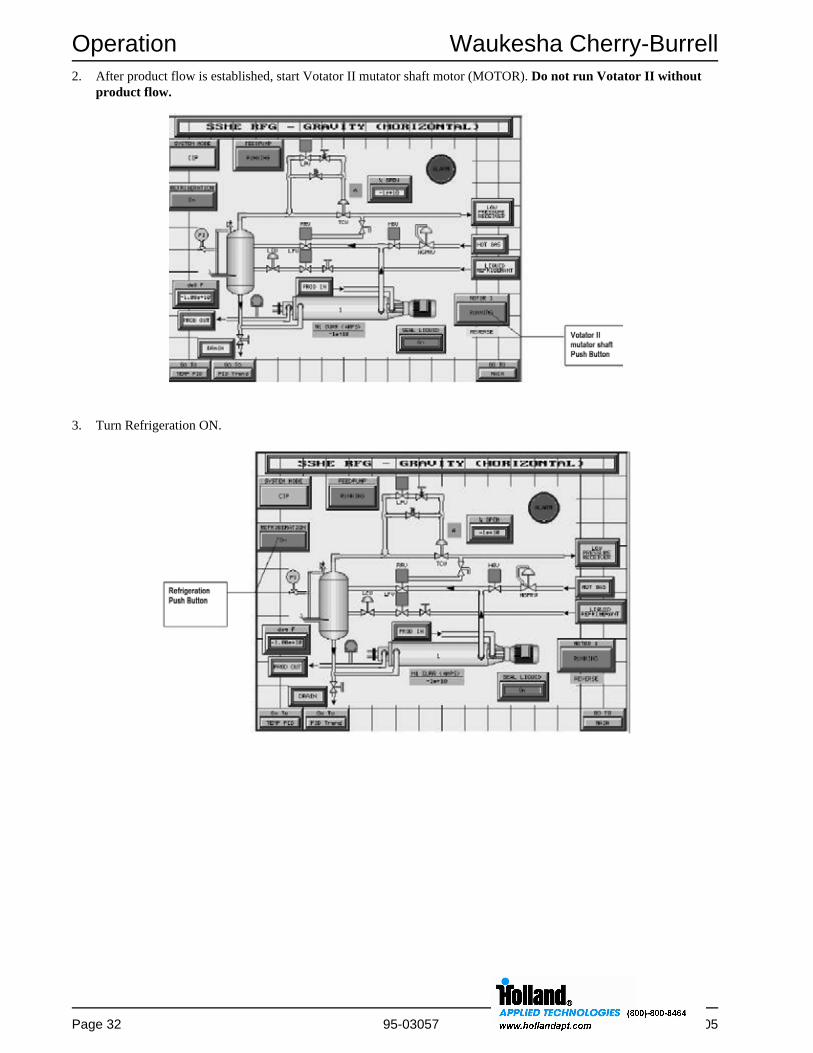
2. After product flow is established, start Votator II mutator shaft motor (MOTOR). Do not run Votator II without product flow.
3. Turn Refrigeration ON.
Waukesha Cherry-Burrell Operation
October 2005 95-03057 Page 33
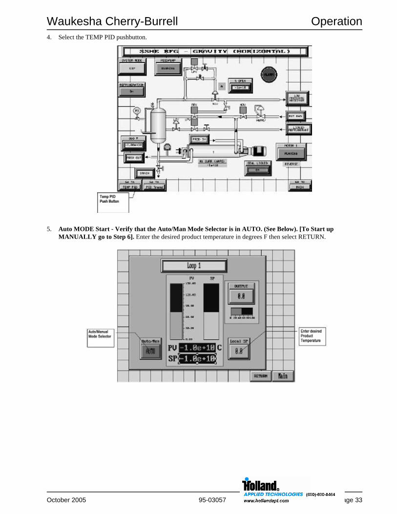
4. Select the TEMP PID pushbutton.
5. Auto MODE Start - Verify that the Auto/Man Mode Selector is in AUTO. (See Below). [To Start up MANUALLY go to Step 6]. Enter the desired product temperature in degrees F then select RETURN.

Operation Waukesha Cherry-Burrell
Page 34 95-03057 October 2005
6. Manual MODE Start - MANUAL PID START UP - Verify the Auto/Man mode selector is in MAN. Enter desired OUTPUT in percent of OPEN valve position. (Enter desired temperature now to prevent going to auto without a temperature setpoint). Observe the PV (Process temperature) as it approaches your desired temperature. When ready, verify that the Local SP value is your desired process temperature in F. and select AUTO mode from the Auto/Manual selector.
7. If running material other than product, switch to product and adjust to desired processing rate.
8. When operating conditions have been reached, redirect product to desired outflow point.

Waukesha Cherry-Burrell Operation
October 2005 95-03057 Page 35
Refrigeration Sequence of Operation
Refer to the Refrigeration Valve functioning guide and the appropriate piping and electrical schematics for the following procedures. If a Votator PLC Control Panel was purchased for the Votator II unit, see the next section Refrigeration Sequence of Operation - PLC Control Panel.
Liquid Overfeed System1. Prior to start up, the Flow Control valves should be set
for the process tonnage.
2. The Refrigerant System Mode switch is placed in the "ON" position. This allows the Votator II Refrigeration switch to be energized in Step 3 below.
3. When the system is ready to be started up, product flow has been established, and the mutator shaft is running, the Votator II Refrigeration switch is placed in the "ON" position. This opens the Liquid Feed Solenoid valve and the Low Pressure EPR valve. The Hot Gas valves and the Purge valves remain closed. The product temperature of the system can now be controlled by adjusting the Low Pressure EPR valve.
4. In the event of high motor amperage as a result of over-cooling, the freeze protection circuitry will, at a preset amperage, close the Low Pressure EPR valve. If the motor amperage decreases, this valve will return to the "OPEN" position. If the motor amperage increases to an overload condition, the mutator drive stops, the Liquid Feed Solenoid valve and the Low Pressure EPR valve close. Hot Gas can be applied to thaw the system using Step 5 below.
5. Placing the Refrigerant System Mode switch in the "DEFROST" position closes the Liquid Feed valve and opens the Hot Gas Inlet valve and the Purge valve. Hot Gas should remain on until the system thaws and the mutator shaft is free to rotate.
6. After a defrost cycle, the system must be restarted following normal start up procedures.
7. When shutting the system down, the Votator II Refrigeration and the Refrigerant System Mode switches should be placed in the "OFF" position and product or flush flow should be maintained until warm up.
8. Turn Votator II mutator drives "OFF".
Gravity Systems1. The Refrigerant System Mode switch is placed in the
"ON" position. This places the system in a standby mode by opening the flow of liquid refrigerant to the accumulator and allowing the level control to function.
2. When the system is ready to be started up, product flow has been established, and the mutator shaft is running, the Votator II Refrigeration switch is placed in the "ON" position. This opens the Refrigerant Return valve on Horizontal units and the Low Pressure EPR valve so the refrigerant back pressure can be controlled, thereby controlling the product temperature.
3. In the event of high motor amperage as a result of over-cooling, the freeze protection circuitry will, at a preset amperage, close the Low Pressure EPR valve and the Refrigerant Return valve if present on system. If the motor amperage decreases, these valves will return to the "OPEN" position. If the motor amperage increases to an overload condition and the mutator drive stops, Hot Gas should be applied to thaw the system using Step 4 below.
4. Placing the Refrigerant System Mode switch in the "DEFROST" position, and placing the Votator II Refrigeration switch in the "OFF" position closes the Liquid Feed valve and opens the Hot Gas Inlet valve. Hot Gas should remain on until the system thaws and the mutator shaft is free to rotate.
5. After a defrost cycle, the system must be restarted following normal start up procedures.
6. When shutting the system down, the Votator II Refrigeration and the Refrigerant System Mode switches should be placed in the "OFF" position and product or flush flow should be maintained until warm up.
7. Turn Votator II mutator drives "OFF".

Operation Waukesha Cherry-Burrell
Page 36 95-03057 October 2005
Refrigeration Sequence of Operation - PLC Control Panel
Liquid Overfeed System1. Prior to start up, the Flow Control valves should be set
for the process tonnage.
2. The Refrigerant System Mode switch is placed in the "ON" position.
3. When the system is ready to be started up, product flow has been established, and the mutator shaft is running, the Votator II Refrigeration push button is pushed to turn Refrigeration "ON". This opens the Liquid Feed Solenoid valve and the Low Pressure EPR valve. The Hot Gas valves and the Purge valves remain closed. The product temperature of the system can now be controlled by the PID local SP setting.
4. In the event of high motor amperage as a result of over-cooling, the freeze protection circuitry will, at a preset amperage, close the Low Pressure EPR valve. If the motor amperage decreases, this valve will return to the "OPEN" position. If the motor amperage increases to an overload condition, the mutator drive stops, the Liquid Feed Solenoid valve and the Low Pressure EPR valve close. Hot Gas can be applied to thaw the system using Step 5 below.
5. Placing the Refrigerant System Mode switch in the "OFF" position closes the Liquid Feed valve. The operator can now "OPEN" the Hot Gas Inlet valve and the Purge valve. Hot Gas should remain on until the system thaws and the mutator shaft is free to rotate.
6. After a defrost cycle, close the Hot Gas Inlet valve and the Purge valve and the system must be restarted following normal start up procedures.
7. When shutting the system down, the Votator II Refrigeration and the Refrigerant System Mode switches should be placed in "OFF" and product or flush flow should be maintained until warm up.
8. Turn Votator II mutator drives "OFF".
Gravity Systems1. The Refrigerant System Mode switch is placed in the
"ON" position. This places the system in a standby mode by opening the flow of liquid refrigerant to the accumulator and allowing the level control to function.
2. When the system is ready to be started up, product flow has been established, and the mutator shaft is running, the Votator II Refrigeration push button is pushed to turn Refrigeration "ON". This opens the Refrigerant Return valve on Horizontal units and the Low Pressure EPR valve so the refrigerant back pressure can be controlled, thereby controlling the product temperature. The product temperature of the system can now be controlled by the PID local SP setting.
3. In the event of high motor amperage as a result of over-cooling, the freeze protection circuitry will, at a preset amperage, close the Low Pressure EPR valve and the Refrigerant Return valve on Horizontal units. If the motor amperage decreases, these valves will return to the "OPEN" position. If the motor amperage increases to an overload condition the mutator drive stops. Hot Gas should be applied to thaw the system using Step 4 below.
4. Placing the Refrigeration switch in the "OFF" position closes the Liquid Feed valve. The operator can now "OPEN" the Hot Gas Inlet valve. Hot Gas should remain on until the system thaws and the mutator shaft is free to rotate.
5. After a defrost cycle, close the Hot Gas Inlet valve and the system must be restarted following normal start up procedures.
6. When shutting the system down, the Votator II Refrigeration and the Refrigerant System Mode switches should be placed in the "OFF" position and product or flush flow should be maintained until warm up.
7. Turn Votator II drives "OFF".

Waukesha Cherry-Burrell Operation
October 2005 95-03057 Page 37
Shutdown Procedure
These instructions are general and should be used only as a guide. It may be necessary to modify them to conform to actual in-plant requirements. Changes should be documented by plant personnel. Emergency Shut-Down procedures should be documented by plant personnel after assessing system-wide requirements.
CAUTION: The steam or refrigeration supply valves must be shut off BEFORE stopping product flow. Failure to do this could result in product burn-on or freezing in heat exchanger cylinders.
Where product characteristics permit, shut off the mutator shaft, the media flow and the pump. Otherwise, it may be necessary to heat or cool the product to ambient temperature to avoid burn-on or freeze-up.
In instances where product goes to a filler, it may be necessary to provide a surge tank or a recirculation line.
With continuous operations, a steam line connected to the product line can enable steam to soften and remove product in the tube at shut down.
The final option is to have hot water chase product from the tube at the end of the run.
Preventing Tube Scoring
Scoring of the heat exchanger tube can have many causes. The most common are temperature extremes, material problems in the heat exchanger tube, or units operated without product or CIP flow.
The following suggestions will help prevent tube scoring:
• Do not pump cold product into a unit that is still hot from cleaning (this can cause temporary bowing of the tube). Wait until the tube has cooled before running cold product.
• Do not leave sterilizing water or solution in the tube after sterilization is complete. Drain the tube completely of sterilizing water or solution. Fill the tube with product prior to starting.
• Make sure that condensate is drained completely in BWS cylinders. The steam trap must be large enough to carry away all condensate.

Maintenance Waukesha Cherry-Burrell
Page 38 95-03057 October 2005
MaintenanceRoutine Maintenance Checklist - Vertical Votator II1. Tools required:
•Rubber or plastic mallet•Large adjustable wrench (2-3/8 inch) or WCB model 79-2 Sanitary Wrench for removing the shaft locknut•Two adjustable or open-end wrenches (15/16 inch) for removing the bearing clamp on the non-driven head•One 3/8 inch nut driver and one common screwdriver for removing the shaft guard on the drive end•One small common screwdriver for removing the keeper o-ring on the seal
2. Lock out power.
3. Drain product piping and disconnect.
4. Position hydraulic lift foot under bottom product head.
5. Loosen latch on bayonet lock and disengage head by rotating clockwise.
6. Lower mutator shaft to floor with hydraulic cylinder.
7. Check conditions of scraper blades and replace if necessary. Service top mechanical seal, if required. Blades are installed with flat side out.
8. If lower mechanical seal needs servicing, remove shaft from lift cradle, or remove two scraper blades from mid section of mutator shaft and raise mutator shaft so that the center of one set of blade pins is positioned in the middle of the bayonet ring.
9. Install shaft lock clamp and secure with locking latch.
10. Lower hydraulic cylinder so that the clamp supports the mutator.
11. Remove the hinge clamp and bearing cap.
12. Remove shaft lock nut (left hand threads) while firmly supporting the product head and carefully removing it from the mutator shaft.
13. The mechanical seals are the same on top and bottom, and if servicing is required:•Remove the keeper o-ring and all seal components, seal body with seal ring, backing ring, u-cup and wavy spring. If it is a double mechanical seal, the secondary seal and spring must be removed before disassembling the primary seal.•Inspect o-rings and seal faces for scratches or cracks. If the seal parts require replacement, refer to pages 52 and 64 or pages 53 and 66.•When assembling the single mechanical seal, place the wave spring on the shaft, followed by the seal backing ring and the u-cup with the opening of the cup facing the body of the shaft. Position the seal body and install the keeper o-ring.•When assembling the double mechanical seal, place the wave spring on the shaft and then the seal body with o-ring. Position the seal body and install the keeper o-ring, followed by the secondary seal and wave spring.•Check all seal assemblies to verify that they are locked in position by the drive pins and that they can be easily compressed.
14. To remove the top product head, remove the shaft guard held in place by four bolts, and rotate the head counter-clockwise to disengage. Check condition of the o-ring in the head before reinstalling.
15. Check conditions of the o-ring in the product head and carefully place the head with bearing on the mutator shaft. The grease ring on the bearing should be facing the product side of the head.
16. Seat bearing in head using a plastic mallet, if required, and install shaft locknut and bearing cap.
17. When installing the mutator shaft in the unit, carefully guide the blades in the cylinder while the mutator is raised. It may be necessary to turn the mutator shaft slightly to align the spline in the motor drive.
WARNING: To avoid injury, the same person should operate the hydraulic controls and guide the mutator shaft.
18. Rotate the product head counter-clockwise to engage the bayonet lock, and close the locking hatch.
19. Grease bearing. (Not required for Extra Heavy Duty Votator II.)

Waukesha Cherry-Burrell Maintenance
October 2005 95-03057 Page 39
Routine Maintenance Checklist - Horizontal Votator II1. Tools required:
•Rubber or plastic mallet•Large adjustable wrench (2-3/8 inch) or WCB model 79-2 Sanitary Wrench for removing the shaft locknut•Two adjustable or open-end wrenches (15/16 inch) for removing the bearing clamp on the non-driven head•One 3/8 inch nut driver and one common screwdriver for removing the shaft guard on the drive end•One small common screwdriver for removing the keeper o-ring on the seal
2. Lock out power.
3. Drain product piping and disconnect.
4. Loosen latch on bayonet lock and disengage head by rotating clockwise.
5. Lift head and pull assembly out about 1 inch, and rest the shaft on the heat transfer tube.
6. Remove the hinged clamp and bearing cap.
7. Remove shaft locknut (left hand threads).
8. Firmly support the product head and carefully remove it from the mutator shaft.
9. Insert plastic shaft skid in unit, install on top and rotate shaft so skid is under shaft. Remove both shaft and skid from unit. Place on a table or cradle.
10. Remove product head on drive end (if required) by removing the shaft guard held in place by four bolts. Rotate the head counter-clockwise to disengage. Check the condition of the o-ring in the head before reinstalling.
11. The mechanical seals are the same on top and bottom, and if servicing is required:•Remove the keeper o-ring and all seal components, seal body with seal ring, backing ring, u-cup and wavy spring. If it is a double mechanical seal, the secondary seal and spring must be removed before disassembling the primary seal.•Inspect o-rings and seal faces for scratches or cracks. If the seal parts require replacement, refer to pages 52 and 64 or pages 53 and 66.•When assembling the single mechanical seal, place the wave spring on the shaft, followed by the seal backing ring and the u-cup with the opening of the cup facing the body of the shaft. Position the seal body and install the keeper o-ring.•When assembling the double mechanical seal, place the wave spring on the shaft and then the seal body with o-ring. Position the seal body and install the keeper o-ring, followed by the secondary seal and wave spring.•Check all seal assemblies to verify that they are locked in position by the drive pins and that they can be easily compressed.
12. Inspect the condition of the scraper blades and replace if necessary. Install the new blades while the shaft is on the cradle or table, attaching two rows of scraper blades on the top of the mutator, and place the shaft skid over the blades. Turn the mutator and shaft skid over so that the skid is on bottom of the table or cradle, and install the other two rows of blades on top. Blades are always installed with the flat side up.
13. Use the shaft skid to slide the mutator in the heat exchanger cylinder and lift up the mutator slightly to remove the shaft skid.
14. Check the condition of the o-ring in the product head and carefully place the product head with bearing on the mutator shaft. The grease ring on the bearing should be facing the product side of the head.
15. Seat bearing in head using a plastic mallet, if required.
16. Install shaft locknut and bearing cap, position product head over bayonet ring and turn counter-clockwise. Close locking latch.
17. Grease bearing. (Not required for Extra Heavy Duty Votator II.)

Maintenance Waukesha Cherry-Burrell
Page 40 95-03057 October 2005
Scheduled MaintenanceThe following table is provided only as a guideline. It may be necessary to modify the schedule to conform to actualin-plant requirements. All changes should be documented by plant personnel.
Table 5: Table of Scheduled Maintenance
Frequency Component Suggested Service
Weekly Mutator Shaft Bearing
Lubricate each fitting with a handgun, approximately three shots. Use a suitable NLGI Grade-2 bearing grease. (Not required for Extra Heavy Duty Votator II.)
Shaft Assembly
Remove shaft assembly at least once a week. Always use the removal trough skid to avoid bottom blades scoring the heat transfer tube. Replace the mechanical seal shell O-rings.
Product Tube Inspect the tube’s inner chrome surface to be sure it is smooth and bright. If rough areas, marks or chrome plating deterioration exist, locate and correct the cause. Replace the tube, if necessary.
Scraper Blades Examine scraper blades weekly, or after 40 operating hours. Based on amount of wear, establish service frequency.
Maintain blades in good condition for longest machine life and best production rates. Reserve a complete set of spare blades for routine replacement. Worn or rough blades reduce heat transfer and can damage the heat transfer tube.
Jacket/Accumulator
Purge gathered oil from accumulator section of accumulator jacket. If ammonia charge is dumped from accumulator daily, oil is carried back with it.
Monthly Inlet and Outlet Fittings
Replace O-rings on inlet and outlet fittings monthly, or more frequently as needed.
Gearmotor Check oil level and add as required.
Semi-Annually
Refrigerant Inspect for oil and/or contaminants.
Flange O-rings Replace O-rings at least every 12-18 months.

Waukesha Cherry-Burrell Maintenance
October 2005 95-03057 Page 41
Preventive Maintenance• Correct problems as soon as they are discovered.
• Inspect equipment frequently following changes in product formulation, processing conditions or CIP regimen.
• Always note and report any abnormal or unusual conditions.
• Follow a regular preventive maintenance schedule. Many factors determine the interval required for scheduled servicing. The severity of the application and the time between scheduled shutdowns are two of the most significant.
When new units are first put into service, they should be disassembled after each production run and inspected for any obvious wear patterns. These initial inspections will establish a process history, as well as provide a basis for establishing a preventive maintenance schedule. Inspections should focus primarily on tube, shaft, blade and seal components. During normal production runs, any abnormal conditions such as unusual noise, leakage or vibration should be noted and corrective action taken.
Mutator Shaft BearingThe Votator II has only one serviceable ball bearing assembly, located in the Opposite Drive End Head of the unit. Lubrication of this bearing while in service is done through the use of the grease fitting located on the Opposite Drive End Head.
Install bearing with lubrication ring in line with grease fitting.
Use a suitable NLGI grade-2 bearing grease for the shaft bearing. Do not over lubricate. Excessively packed bearings will over heat and fail prematurely.
Frequency of lubrication is dependant on the environment; daily if it is in contact with water or steam, otherwise weekly lubrication usually is sufficient.
WARNING: Never immerse the Front Mutator Shaft Bearing in cleaning solution or subject to steam. Clean bearing with a dry cloth and lubricate.
Inspection of bearing should be ongoing. If looseness is detected, replace bearing immediately. Worn out bearings cause shaft misalignment that will cause mechanical seals and gearbox to wear out prematurely.
Extra Heavy Duty Votator II Shaft BearingThe shaft bearing on the Extra Heavy Duty Votator II located in the opposite drive end head is a sealed bearing and does not require lubrication.
ShaftsAll shaft surfaces, especially in seal and bearing areas, should be kept smooth and clean. Special care should be taken while cleaning and maintaining seals and bearings to assure that these areas of the shaft are not scratched or damaged.
Shaft porosity can be detected by making an adaptor for the threaded end of the shaft and pressurizing it with air. Pinholes will be detected as air bubbles by submersing the shaft in a water bath. Leaky shafts can be repaired at WCB.
Bent or imbalanced shafts will cause premature bearing, seal and blade wear and may damage tube walls. Shafts should be checked for straightness and balance annually.
Gear DriveManufacturer recommendations should be followed for gear oil replacement. When draining oil, examine closely for foreign matter or debris, flushing or gear replacement may be required.
Use Lubricant FMO-1100-AW on the Nord gearbox. A suitable equivalent is 90 weight food grade gear lube.
The fill capacity for an empty gearbox is 5.71 quarts.
BladesBlades that have developed a heel greater than WCB specifications should be sharpened per instructions in this manual. Blades worn beyond the minimum sharpening dimensions should be replaced. Worn blades reduce heat transfer, result in poor performance and may damage product tubes. See “Scraper Blade Maintenance” on page 44.
Figure 18 - Lubrication Ring Orientation

Maintenance Waukesha Cherry-Burrell
Page 42 95-03057 October 2005
Mechanical SealsVotator II heat exchangers are equipped with single or double mechanical seals at each end of the mutator shaft.
NOTE: Double mechanical seals MUST BE flushed to prevent seal faces from over heating.
Mechanical seal faces with nicks, blisters, grooves, or any abnormality on the seal face, must be replaced. Elastomers that are brittle, deformed, cut, or have any abnormality must be replaced. It is an excellent practice to replace all elastomers and gaskets whenever maintenance is performed.
TubesA frequent cause of tube wall damage is careless handling when removing or installing the mutator shaft. The shaft trough skid should always be used when removing or installing the mutator shaft in the Horizontal Votator II (or the Vertical unit if in a horizontal position) to prevent the blade mounting pins from scoring and damaging the tube wall.
A common way to damage tube ends is to bang or drop the shaft journals when removing or inserting the shaft.
Tubes should be examined for wear anytime the shaft is removed or at least once every 3 months. Chrome plated tubes should be inspected for flaking of the chrome. Normally, tubes will develop phonographic patterns from blade contact and rotation; this phonographic pattern is generally visible to the eye but is not significant unless detectable by touch. Scoring is significant when the base metal has been damaged; roughness of the tube wall is obvious both visually and by touch. A badly scored tube will make cleaning more difficult, reduce heat transfer, result in poor performance and increase blade wear.
Re-conditioning the tube is the only way to restore performance. If there is suspicion that scoring has penetrated the tube wall, the unit can be pressure tested by turning on the jacket media and observing the inside of the tube for leaks.
Tubes should be removed every 12 to 18 months for cleaning debris from the media side. Jacket side O-rings should be replaced when tubes are reinstalled.
Care of Heat Exchanger TubeNOTE: Repair work must be performed by a shop with ASME certified welders. The heat exchanger tubes are ASME coded parts. Failure to get repairs done by an ASME coded machine shop with certified welders will void the warranty and possibly void insurance. SPX Process Equipment has all required certifications necessary for repair of ASME coded parts.
Product SideThe heat exchanger tube is designed to last a long time with little maintenance.
If tubes wear out prematurely, one or more of the following may be the cause:
• Failure to use shaft trough when removing mutator shaft will cause scratching or gouging of tube wall.
• Careless assembly and installation of blades.
• Rotating shaft without product or product flow.
• Use of the wrong detergent or incorrect use of a detergent.
• Starting shafts against stiffened or solidified product in tubes.
• Starting the flow of jacket media (Ammonia, Freon, Steam, Water, etc.) before establishing full product flow under operating pressures.
• Failure to clear tubes of product after every use.
• Starting operation before dissolving particles such as salt, sugar, detergents, etc.
• Using dull blades or blades that have been sharpened below minimum width specifications.
• Using blades other than those furnished by Waukesha Cherry-Burrell.
• Worn mutator shaft bearings.
Waukesha Cherry-Burrell Maintenance
October 2005 95-03057 Page 43
Inspection of Chrome Plated Nickel or Stainless Steel TubesDuring each inspection of the scraper blades, inspect the inside surface of the tube for scoring, gouging, and roughness. When the surface of the plating is damaged or worn through, it may be rechromed to original specifications by Waukesha Cherry-Burrell. WCB has the equipment and product knowledge to repair the tube back to factory specifications and determine if the tube will comply with ASME specifications.
CAUTION: Acid cleaners are not recommended for chrome plated nickel heat transfer tubes. Cleaners should be compatible with the elastomers in the heat exchanger.
Inspection of Stainless Steel TubesDuring each inspection of the scraper blades, inspect the inside surface of the tube for scoring, gouging, and roughness. Shallow score marks, shallow gouges, and roughness can be taken out by honing the tube followed by polishing. Depending on the damage to the tube, Waukesha Cherry-Burrell may be able to rehone the tube to comply with ASME code specifications.
Jacket Side
For Units Using Steam, Water, Or LiquidThe jacket side of the heat transfer tube has a sealed cover that allows the media flow to circulate around the tube. If it becomes coated with foreign matter and heat transfer is reduced, it can be cleaned by pumping a detergent solution compatible with the carbon steel jacket at a rate of about 100 gpm. The frequency of this cleaning process will vary greatly from one installation to another.
For Units Using RefrigerantThe jacket side of the heat transfer tube will become fouled with oil and sludge over time and prevent efficient heat transfer. This tube does not have a sealed flow spiral and can be cleaned by removing it from the jacket. It should be removed for cleaning every 12 to 18 months.
NOTE: If you plan to clean the tube with anything other than the materials and methods mentioned previously, please contact Waukesha Cherry-Burrell.
Cleaning the FlangesRemove the O-rings and clean the grooves thoroughly of all residue and buildup. Care must be taken in cleaning the flanges, as they are part of the seal mechanism of the unit.
Install new O-rings any time the unit is disassembled.
NOTE: Replace the O-rings every 12-18 months.
Lubricate the O-rings.
Leak TestingEach cylinder is thoroughly tested for leaks at the factory. It is necessary to check for leaks in the refrigeration system any time the piping is opened to the atmosphere for maintenance or repair.
WARNING: Do not open valves or check for leaks until the electrical system checkout is completed. Personnel must wear safety goggles and protective clothing.

Maintenance Waukesha Cherry-Burrell
Page 44 95-03057 October 2005
Scraper Blade Maintenance
Blade InspectionThe blades should be inspected for wear and signs of fatigue or cracking at the pin location and should be replaced if damage has occurred. Failure to replace damaged blades may result in breakage, which can damage other blades or the heat transfer tube, and result in blade particles in the product.
CAUTION: High concentrations of acid or caustic should be avoided if plastic scraper blades are used. Cleaners should be compatible with the elastomers in the heat exchanger.
Scraper Blade Removal & Replacement1. Scraper blades are removed by lifting up and pulling
them from the pins. PEEK Blades have a locking groove. After lifting, push to the right before pulling them from the pins.
NOTE: Blades should be kept in the same position on mutator shaft throughout life of blade. Make sure blades are removed and reinstalled in the same location on the shaft.
Reverse this procedure for installation. Make sure beveled edge is installed toward shaft.
Scraper Blade WearWorn blades reduce heat transfer efficiency and can cause excessive wear on the product tube wall.
As the scraper blades scrape across the interior of the heat exchanger tube, they wear into the contour of the tube. A flat surface called the heel and a burr or feathered edge develops at the contact area on the side of the blade that is against the tube wall. See Figure 20.
The blades must be maintained to achieve maximum performance. When the heel of the blade reaches a maximum of 1/16" (1.6 mm) on metal blades or 1/8" (3.2 mm) on plastic blades, they must be replaced or re-sharpened.
Blade SharpeningScraper blades can be sharpened by several methods, depending on the blade material.
The best method utilizes a high speed 45° cutter and fixture that keeps the backside of the blade perpendicular to the cutting edge. The cutting edge of the blade should be parallel to the back surface of the blade within 1/64".
A new universal blade is 2 inches wide by 6 inches long.
For mutator shafts that are 4-1/2 inches in diameter or larger, the blade should not be sharpened to a blade width of less than 1-3/8 inches.
For mutator shafts that are 4 inches in diameter, the blade should not be sharpened to a blade width of less than1-1/2 inches.
Stainless steel blades for the 5-1/4 inch mutator shafts are 1-9/16 x 23-29/32. The minimum width after sharpening is 1-3/8 inches and the sharpening edge is at a 15-degree angle.
Figure 19 - Scraper Blade Removal
Figure 20 - Blade Wear and Sharpening
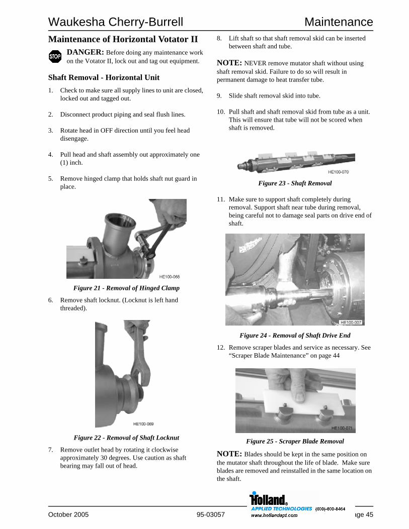
Waukesha Cherry-Burrell Maintenance
October 2005 95-03057 Page 45
Maintenance of Horizontal Votator IIDANGER: Before doing any maintenance work on the Votator II, lock out and tag out equipment.
Shaft Removal - Horizontal Unit1. Check to make sure all supply lines to unit are closed,
locked out and tagged out.
2. Disconnect product piping and seal flush lines.
3. Rotate head in OFF direction until you feel head disengage.
4. Pull head and shaft assembly out approximately one (1) inch.
5. Remove hinged clamp that holds shaft nut guard in place.
6. Remove shaft locknut. (Locknut is left hand threaded).
7. Remove outlet head by rotating it clockwise approximately 30 degrees. Use caution as shaft bearing may fall out of head.
8. Lift shaft so that shaft removal skid can be inserted between shaft and tube.
NOTE: NEVER remove mutator shaft without using shaft removal skid. Failure to do so will result in permanent damage to heat transfer tube.
9. Slide shaft removal skid into tube.
10. Pull shaft and shaft removal skid from tube as a unit. This will ensure that tube will not be scored when shaft is removed.
11. Make sure to support shaft completely during removal. Support shaft near tube during removal, being careful not to damage seal parts on drive end of shaft.
12. Remove scraper blades and service as necessary. See “Scraper Blade Maintenance” on page 44
NOTE: Blades should be kept in the same position on the mutator shaft throughout the life of blade. Make sure blades are removed and reinstalled in the same location on the shaft.
Figure 21 - Removal of Hinged Clamp
Figure 22 - Removal of Shaft Locknut
Figure 23 - Shaft Removal
Figure 24 - Removal of Shaft Drive End
Figure 25 - Scraper Blade Removal

Maintenance Waukesha Cherry-Burrell
Page 46 95-03057 October 2005
Shaft Installation - Horizontal Unit1. If opposite drive end head has been removed, make
sure O-ring (See Figure 26, Item A) is installed in opposite drive end head.
2. Install drive end head (if necessary).
3. Install mechanical seal on drive end of shaft as shown in Figure 27. See “Mechanical Seal Maintenance” on page 52.
4. Install all scraper blades on mutator shaft.
NOTE: Blades should be kept in the same position on mutator shaft throughout life of blade. Make sure blades are removed and reinstalled in the same location on the shaft.
5. Place shaft in shaft removal skid.
6. Push shaft and shaft removal skid into tube as a unit. This will ensure that tube will not be scored when shaft is replaced.
7. Push spline of shaft partially into gear reducer. Shaft may need to be rotated slightly for splines to seat in gear reducer. See Figure 28.
8. Lift shaft slightly to remove shaft removal skid.
9. Make sure O-ring (See Figure 29, Item A) is installed in drive end head.
10. Install opposite drive end head by reversing procedure for removal of head.
11. Install shaft bearing in head.
12. Lift the shaft and head, place over the tube ring and position bayonet closure. Close locking latch and secure by tightening latch retainer nut.
Figure 26 - Opposite Drive End Head O-ring
Figure 27 - Mechanical Seal Installation
Figure 28 - Align Shaft Splines with Gear Reducer
Figure 29 - Drive End Head O-ring
Figure 30 - Install Head Shaft Bearing

Waukesha Cherry-Burrell Maintenance
October 2005 95-03057 Page 47
13. Install shaft nut onto shaft (nut is left hand threaded) and tighten nut against bearing’s inner race.
14. Push on bearing retainer and secure with clamp.
15. Install all product connections and seal flush piping.
16. Inspect unit for correct assembly.
17. Remove tag-out and lock-out. Prepare unit for operation.
Heat Exchanger Tube Removal - Horizontal Unit
DANGER: Before doing any maintenance work on the Votator II, lock out and tag out equipment.
1. Check to insure all supply lines to unit are closed and locked and tagged out.
2. Make sure that entire unit is purged of fluids (product, coolant, refrigerant, etc.)
3. Remove mutator shaft and drive end head as described in this section.
DANGER: Before removing the heat exchanger tube from the jacket, all refrigerant must be evacuated from the jacket assembly.
4. Remove locking latch and associated hardware that holds front cover in place.
5. Remove the eight (8) 3/8-inch bolts that hold removable tube to jacket. See Figure 33.
6. Take four (4) bolts and thread them into the “B” holes. The “B” holes are located at the 12, 3, 6, and 9 o’clock locations. DO NOT TIGHTEN!
7. Using an X pattern, gradually tighten bolts to withdraw tube from jacket. Considerable effort may be needed to overcome any stickiness.
If tube does not start to pull away from jacket as bolts are tightened, stop and do the following:
• Make sure product head on drive end is removed.
• Place a block of wood across drive end of tube and apply pressure to force tube opposite the drive end.
• When tube is loose, use bolts to complete removal.
• If tube cannot be budged, contact SPX Process Equipment.
8. Pull tube out of jacket. Care should be taken to avoid marring jacket cylinder during heat transfer tube removal. Mark tube and jacket so that tube can be reinstalled in same jacket. See Figure 34. On BWS or liquid units, install a new packing ring.
Figure 31 - Installation of Shaft Locknut
Figure 32 - Installation of Hinged Clamp
Figure 33 - Removal of Tube to Jacket Bolts
Figure 34 - Tube Removal

Maintenance Waukesha Cherry-Burrell
Page 48 95-03057 October 2005
Heat Exchanger Tube Installation - Horizontal Unit1. Inspect jacket cylinder interior and wipe out all dirt
and impurities.
2. Lubricate sealing surfaces inside jacket cylinder and install new O-rings in the tube.
3. Carefully insert tube into jacket cylinder. Support pins of heat exchanger tube should be at 5 o’clock and7 o’clock positions during insertion.
4. Push tube into cylinder as far as it will go.
5. Thread the eight (8) 3/8-inch bolts through the flange of heat exchanger tube into jacket cylinder.
6. Tighten bolts in a crossing pattern until tube is snugged down to jacket cylinder.
7. Torque bolts to 240 in-lbs (20 ft-lbs).
8. Install front cover.
9. Install latch hardware.
10. Install drive end head.
11. Install shaft (with mechanical seals).
12. Install opposite drive end head.
Maintenance of Vertical Votator IIDANGER: Before doing any maintenance work on the Votator II, lock out and tag out equipment.
Shaft Removal - Vertical Unit1. Purge all product from unit.
2. Disconnect product piping from opposite drive end head.
3. Lower arm of hydraulic lift so that arm can be positioned under opposite drive end head. (See Figure 36, Item A).
4. Raise arm of hydraulic lift to just below opposite drive end head (See Figure 36, Item B) and position lift pin (See Figure 36, Item C) to go into shaft nut.
5. Raise arm so that lift pin is engaged in head and just barely pushing against shaft nut.
WARNING: Do not move latch or loosen nut from locked position without hydraulic foot in place beneath head.
6. Unlatch locking latch.
Figure 35- Install Tube to Jacket BoltsFigure 36- Location Of Hydraulic Arm For Removal
Figure 37 - Disengaging Locking Latch
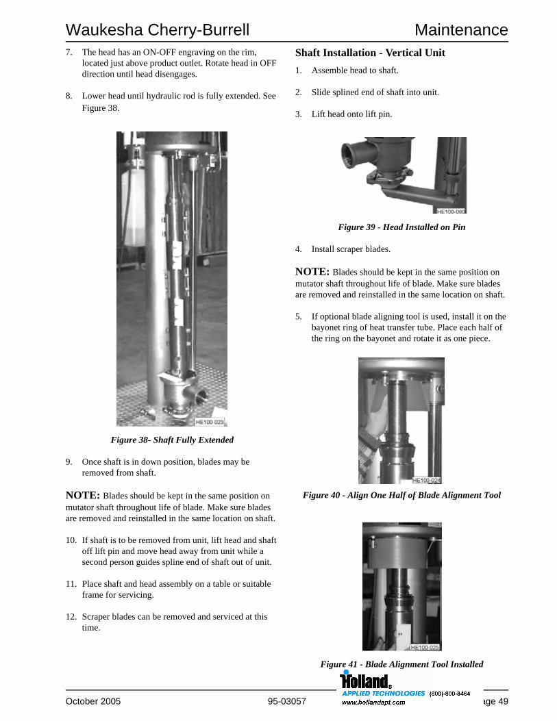
Waukesha Cherry-Burrell Maintenance
October 2005 95-03057 Page 49
7. The head has an ON-OFF engraving on the rim, located just above product outlet. Rotate head in OFF direction until head disengages.
8. Lower head until hydraulic rod is fully extended. See Figure 38.
9. Once shaft is in down position, blades may be removed from shaft.
NOTE: Blades should be kept in the same position on mutator shaft throughout life of blade. Make sure blades are removed and reinstalled in the same location on shaft.
10. If shaft is to be removed from unit, lift head and shaft off lift pin and move head away from unit while a second person guides spline end of shaft out of unit.
11. Place shaft and head assembly on a table or suitable frame for servicing.
12. Scraper blades can be removed and serviced at this time.
Shaft Installation - Vertical Unit1. Assemble head to shaft.
2. Slide splined end of shaft into unit.
3. Lift head onto lift pin.
4. Install scraper blades.
NOTE: Blades should be kept in the same position on mutator shaft throughout life of blade. Make sure blades are removed and reinstalled in the same location on shaft.
5. If optional blade aligning tool is used, install it on the bayonet ring of heat transfer tube. Place each half of the ring on the bayonet and rotate it as one piece.
Figure 38- Shaft Fully Extended
Figure 39 - Head Installed on Pin
Figure 40 - Align One Half of Blade Alignment Tool
Figure 41 - Blade Alignment Tool Installed

Maintenance Waukesha Cherry-Burrell
Page 50 95-03057 October 2005
6. Raise shaft slowly, tucking blades into shaft while shaft and blade assembly is being inserted into tube.
NOTE: If lift binds, STOP and back off hydraulic pressure. Check that blades have not swung fully out and are not binding on the edge of alignment tool. If this happens, check blades and replace as necessary. Restart lift, taking care to guide blades into alignment tool.
7. If blade aligning tool is not used, the individual controlling hydraulic lift should use one hand to guide each pair of blades into tube.
8. As shaft is raised into gear reducer, it may be necessary to rotate shaft slightly to assure splines are meshed correctly.
9. Continue to raise shaft until head is about six (6) inches from being engaged.
10. Once the last set of blades has been started in tube, remove alignment tool, if used.
11. Continue to raise head slowly, aligning teeth of head with spaces of tube. Raise and turn head so teeth are engaged and product port is facing forward.
12. Close locking latch. See Figure 42.
13. Install product piping and electrical connections.
Heat Exchanger Tube Removal -Vertical UnitThe hydraulic lift on the vertical unit can be used to remove the heat transfer tube from the jacket of the unit.
DANGER: Before removing the heat exchanger tube from the jacket, all refrigerant must be evacuated from the jacket assembly.
1. Remove mutator shaft from unit as described in this section.
2. Remove shaft and head from hydraulic lift.
3. Place assembly on a table or maintenance frame.
4. Remove the driven end product head.
5. Remove the three (3) bolts holding front jacket cover in place.
6. Remove the non-driven product head from mutator shaft.
7. Reattach head to tube. See Figure 44. Reattach shaft nut cover and clamp, and use lift to position non-driven end head.
8. Loosen bolts on jacket flange.
9. Lower head slightly with hydraulic cylinder to allow tube to move down.
NOTE: Tube may slide out easily or it may need coaxing out.
Figure 42 - Close Locking Latch
Figure 43 - Remove Front Jacket Cover Bolts
Figure 44 - Head Reinstalled

Waukesha Cherry-Burrell Maintenance
October 2005 95-03057 Page 51
10. Lower lift arm slightly to allow tube to move down. At the 12, 6, 3, and 9 o’clock positions, tube flange is threaded for jack screws. Thread two (2) bolts into either the 12 & 6 or 3 & 9 o’clock positions.
11. Tighten bolts about 1/2 turn alternately on each side until flange loosens from jacket. It may be necessary to lower foot on hydraulic cylinder slightly while removing tube from jacket.
12. Lower head and tube assembly and service as required.
13. Lubricate and install new O-rings on both ends of tube.
14. Install new packing ring (on steam or liquid tubes).
15. To reinstall tube, reverse the procedure.
16. Torque bolts to 240 in-lbs (20 ft-lbs).
NOTE: Care must be taken to orient tube flange holes to line up with holes in jacket.
Figure 45 - Insert Jack Screws
Figure 46 - Lower Tube and Service

Maintenance Waukesha Cherry-Burrell
Page 52 95-03057 October 2005
Mechanical Seal MaintenanceThe mechanical seals on the Votator II are the same on both the non-driven and driven ends of the unit. TheO-rings and seal materials have been selected for the product specifications. Various options are shown in the Parts Lists starting on page 58.
Single Mechanical SealUnits furnished before 2005 were installed with either a single or double mechanical seal configuration. For detailed parts drawing breakdown See “Single Mechanical Seal” on page 64.
Seal Head Insert Removal and InstallationThe Seal Head Insert located in the product head is removed by tapping the back of the seal with a plastic block or rod. Make sure to hold the insert or use a soft cloth to catch it to prevent it from dropping when removed.
NOTE: To prevent damage to the seal face do not place the seal face down on any surface during maintenance.
If the mechanical seal is going to be flushed, the springs in the lip seal should be removed to protect the stub ends on the mutator shaft. Install the seal in the relief position as shown in Figure 48.
To install a new insert, lubricate the o-rings and the inside bore. Insert in the head with an even distribution of force on the face. The face must be protected with plastic to avoid damage.
Seal Body Insert (Rotating Seal Face)The rotating seal face is referred to as the Seal Body Insert. This part is designed to wear at a greater frequency than the seal head insert. An O-ring holds the insert stationary in the seal body.
NOTE: Do not use a lubricant on the Seal Body Insert O-ring because the insert must remain stationary with respect to the body. If necessary water can be used as a lubricant.
The seal insert is symmetrical and can be reversed if one side becomes scratched.
The seal body is held in place on the mutator shaft by two seal drive pins. Each one should be 3/32 inches (+/-0.015) above the stub shaft surface. It is extremely important that these pins are not rounded on the edges and this dimension is maintained. If the pins are higher than 3/32", the seal will jam; if the pins are too low, the body will rotate. See Figure 51.
Install the Seal Body Insert in the Seal Body as follows:
1. Place O-ring in Seal Body.
2. Push Seal Body Insert down evenly with both hands until it bottoms out. See Figure 49.
Figure 47 - Seal Head Insert Removal
Figure 48 - Lip Seal Orientation
Figure 49 - Press Insert Down Evenly with Both Hands

Waukesha Cherry-Burrell Maintenance
October 2005 95-03057 Page 53
Single Mechanical Seal Installation
After the head insert and the body insert are installed, the remaining components are installed as follows:
1. Place wavy washer spring (See Figure 50, Item A) on shaft.
2. Install seal back-up ring. (See Figure 50, Item B).
3. Install U cup seal with opening toward product side, as shown in Figure 50, Item C.
4. Place seal body (See Figure 50, Item D) on shaft, aligning slots with seal drive pins.
5. Install "keeper" O-ring (See Figure 51, Item E) on shaft to keep rotating parts assembled.
6. Inspect seal to insure that it moves freely with spring and that drive pins keep it stationary with respect to mutator shaft.
One-Piece and Double Mechanical SealsFor detailed parts drawing breakdown See “Double Mechanical Seal” on page 66. Units furnished before 2005 had a removable seal body insert as described below. In 2005, all single and double mechanical seals were furnished with a one-piece primary seal body.
Primary/Secondary Seal Head Insert Removal and InstallationThe primary seal head insert located in the product head is removed by tapping the back of the seal with a plastic block or rod. It contains the secondary seal head insert and the two parts can be removed as an assembly or separately, as the secondary ring is held in the primary by an O-ring. Make sure to hold the insert or use a soft cloth to catch it to prevent it from dropping when removed.
NOTE: To prevent damage to the seal face, do not place seal face down on any surface during maintenance.
To install a new primary or secondary insert, lubricateo-rings and the inside bore. Insert in the head with an even distribution of force on face. Face must be protected with plastic to avoid damage.
One-Piece Primary Seal Body (Rotating Seal Face)
Figure 53a - One-Piece Seal Body
Figure 50 - Orientation of Seal Components
Figure 51 - Install Keeper O-ring
Figure 52 - Seal Head Insert Removal

Maintenance Waukesha Cherry-Burrell
Page 54 95-03057 October 2005
Removable Seal Body Insert (Rotating Seal Face)The rotating seal face is referred to as the Seal Body Insert. This part is designed to wear at a greater frequency than the seal head insert. An O-ring holds the insert stationary in the seal body. Assembly is described in the following section.
Assembly of Removable Primary Seal BodyThe Primary Seal Body has two O-rings, one on the outside diameter of the ring and the other on the inside diameter that holds the ring stationary.
The O-rings can be hand stretched slightly to fit snugly in the grooves. Preferred assembly is with the O-ring dry. If necessary, water or soapy water can be used as a lubricant.
1. Install one O-ring (See Figure 53, Item B) on outside diameter of ring.
2. Install other O-ring (See Figure 53, Item A) on inside diameter of primary seal.
3. Push insert down evenly with both hands until it bottoms in the housing.
4. Vent trapped air by placing a small flat screwdriver blade between seal ring and outside O-ring.
NOTE: Air can be become trapped behind Primary Seal Insert after assembly. This air must be vented by placing a small flat screwdriver blade between seal ring and outside O-ring to provide a vent for trapped air.
5. While the screwdriver is in place, push down firmly on ring.
6. Release screwdriver and check seal to insure that it firm and solid.
7. Place the inner O-ring in the seal body (lubrication should be applied to this O-ring).
Secondary Seal Body Assembly (For Double Mechanical Seal Only)The secondary seal body has one O-ring that holds the insert stationary in the body.
To install the insert in the seal body:
1. Place O-ring in body (no lubrication).
2. Push insert down evenly with both hands until it bottoms out.
3. Place O-ring in seal body (lubrication should be applied to this O-ring).
Seal Assembly Installation on ShaftAfter the head insert and the body insert are installed, the remaining components are installed as follows:
1. The primary seal body is held in place on the mutator shaft by two seal drive pins. Each on should be 5/32 inches (+/- 0.015") above the stub shaft surface. The secondary seal body is held in place by one seal drive pin. It should be 3/32 inch (+/-0.015") above the stub shaft surface. It is extremely important that these dimensions be maintained. If the pins are too high, the seal will jam; if they are too low, the body will rotate. See Figure 55 and Figure 58.
Figure 53b - O-ring Installation on Primary Seal
Figure 54 - Press Insert Down Evenly with Both Hands

Waukesha Cherry-Burrell Maintenance
October 2005 95-03057 Page 55
2. Place wavy washer spring (See Figure 55, Item A) on shaft.
3. Place seal body (Figure 56) or one piece seal on shaft, aligning slots with seal drive pins.
4. Install "keeper" O-ring (See Figure 57, Item E) on shaft to keep rotating parts assembled.
5. Inspect seal to insure that it moves freely with spring and that drive pins keep it stationary with respect to the mutator shaft.
6. Assemble Secondary Seal Wavy Washer on shaft, if required (See Figure 58).
7. Slide seal body over seal body drive pin so that O-ring in body seats in groove in mutator shaft.
8. Check seal to insure that it will move freely with spring and that drive pins hold it stationary with respect to shaft.
Servicing Mechanical Seals - Vertical Votator IIThe top mechanical seal can be serviced by lowering the shaft to the floor and removing the seals from the shaft while the spline end is in the heat transfer tube. See Figure 59. See “Mechanical Seal Maintenance” on page 52 for information regarding servicing the seal.
The bottom mechanical seal can be serviced with the mutator shaft in the unit by using the shaft clamp. See Figure 60.
Figure 55 - Install Wavy Spring
Figure 56 - Install Seal Body
Figure 57 - Install Keeper O-ring
Figure 58 - Double Mechanical Seal Installed
Figure 59 - Exposing Top Mechanical Seal

Maintenance Waukesha Cherry-Burrell
Page 56 95-03057 October 2005
1. Lower shaft approximately two (2) feet or to a convenient height.
2. Remove top two (2) exposed scraper blades.
3. Position shaft so that blade pins are centered between the bayonet ring on the heat transfer tube.
4. Install shaft clamp around teeth of tube and shaft.(See Figure 61, Item A)
5. Close locking latch. (See Figure 61, Item B)
6. Lower shaft until a pin from right or left side contacts shaft clamp. SHAFT MUST BE SUPPORTED BY A PIN AND NOT BY A SCRAPER BLADE.
7. Lower hydraulic arm and rotate it out of the way.
8. Remove clamp on head. (See Figure 62, Item A) and shaft nut guard.
9. While supporting head, remove shaft nut. (Nut is left hand threaded.)
Figure 60 - Shaft Clamp
Figure 61 - Installed Shaft Clamp
Figure 62 - Remove Head Clamp

Waukesha Cherry-Burrell Maintenance
October 2005 95-03057 Page 57
10. Grasp head with both hands, remove it from shaft.
11. Seals can now be serviced. See “Mechanical Seal Maintenance” on page 52.
12. To install, reverse the procedure.
s
Figure 63 - Shaft With Head Removed

Parts Lists Waukesha Cherry-Burrell
Page 58 95-03057 October 2005
Parts Lists
Labels..........59
Cylinder Assembly..........60
Latch..........61
Product Heads..........61
Cylinder Assembly - Shaft..........62
Cylinder Assembly - Removable Tube..........63
Single Mechanical Seal..........64
Double Mechanical Seal..........66
Vertical Refrigeration Piping..........68
Vertical Frame/Hydraulics..........70
Shaft Heater (Optional)..........71
Votator II Recommended Spare Parts..........72

Waukesha Cherry-Burrell Parts Lists
October 2005 95-03057 Page 59
Labels
PART NUMBER DESCRIPTION
927603 3A Authorization
925499 Caution/Warning Shaft Guard
119169 Danger - Contents Under Pressure
119170 Safety Instructions
930514 Votator II Logo Horizontal
930513 Votator II Logo Vertical
931360 Caution/Warning Product Head Locking Latch
931407 Caution/Warning Product Head Locking Latch

Parts Lists Waukesha Cherry-Burrell
Page 60 95-03057 October 2005
Cylinder Assembly
ITEM # PART DESCRIPTION QTY MODEL/MATERIAL PART #12 Jacket O-ring (Drive End)
2EPDM E75444Neoprene (Rfg) R70444Fluoroelastomer V75444
13 Blades
AR
PEEK 118683410 SS 900127Celcon 900129Brass 918089410 SS (5-1/4" dia only) 926752
14 Packing, Concentric and Eccentric 1 BWS only 710015Packing, Oval 1 Liquid Jacket 710296
15 Jacket O-ring (Opposite Drive End)2
EPDM E75446Neoprene (Rfg) R70446Fluoroelastomer V75446
16 Heavy Hex Head Bolt 3/8-16 x 1 8 ASME SA193-B8, Class 1 92878119 Bearing Retainer 1 Votator II 923214
Extra Heavy Duty Votator II 11839319B Clamp Ring 1 Spider Head Only LL11767820 Shaft Nut Guard
1Horizontal 923212W/ Shaft Heater (horz or vert) 929346Vertical
21 Shaft Locknut 1 Votator II 119275AExtra Heavy Duty Votator II 118395
21A Shaft Locknut Wrench 1 All 79-221B Hex Head Cap Screw 1 Spider Head Only 71893422 Ball Bearing 1 Votator II 923215
Extra Heavy Duty Votator II 11839222B Sleeve Bearing 1 Spider Head Only 117679F23 Hinged Sanitary Clamp 1 Votator II 0346223
Extra Heavy Duty Votator II 034822324 Bearing Sleeve 1 Extra Heavy Duty Votator II 118394
24B Shaft Sleeve 1 Spider Head Only 117680C
(Extra Heavy Duty Bearing Option)
Press Sleeve 24 into bearing 22 to assemble.

Waukesha Cherry-Burrell Parts Lists
October 2005 95-03057 Page 61
Latch
Product Heads
CAUTION: Product heads comply with the ASME pressure vessel code and must not be changed between units of the same design. Also, a concentric head is not interchangeable with an eccentric/oval design.
ITEM # PART DESCRIPTION QTY PART #
35 VII Locking Latch 1 923221
36 Washer Plain 3/8” 18-8 Narrow 8 43-30
37A Wing Nut 1
37B Acorn Nut 1 711155
38 Spacer 3 2200321
39 Stud 1 2200277
40 Hexagon Head Shoulder Screw 1 925499
52 Spacer Washer 1 931315
APPLICATION DESCRIPTION PART #
Opposite Drive End Concentric 3” I-Line 923245Concentric 3” Flanged 118415Concentric/XHD Bearing 3” Flanged 120325Concentric/XHD Bearing 3” I-Line 119402Eccentric 3” I-Line 118337Eccentric 3” Flanged 118419Eccentric/Oval/XHD Bearing 3” Flanged 120326Eccentric/Oval/XHD Bearing 3” I-Line 118391Eccentric/Oval Spider Head 121314Concentric Spider Head 121359
Drive End Concentric 3” I-Line 923255Concentric 3” Flanged 118414Eccentric/Oval 3” I-Line 118336Eccentric/Oval 3” Flanged 118418

Parts Lists Waukesha Cherry-Burrell
Page 62 95-03057 October 2005
Cylinder Assembly - Shaft
Table 6: Cylinder Assembly Item 33 (Shaft) - Part Numbers
SIZE SEAL TYPE SHAFT MODEL PART # SEAL TYPE SHAFT
MODEL PART #
6 x 24 Single Mechanical 5-1/4" dia 118919 Double Mechanical 4-1/2" dia 9368816 x 36 Single Mechanical 2-1/2" dia 935989 Double Mechanical 2-1/2" dia NA
4" dia NA 4" dia 9355184-1/2" dia 936898 4-1/2" dia 9355635-1/4" dia NA 5-1/4" dia NAECC 930524
6 x 48 Single Mechanical 2-1/2" dia 935987 Double Mechanical 2-1/2" dia NA4" dia NA 4" dia NA4-1/2" dia 936476 4-1/2" dia 9367865-1/4" dia 935921 5-1/4" dia NAECC 4" dia 936764 ECC 4" dia 936743EHD 4" dia NA EHD 4" dia 122335
6 x 72 Single Mechanical 2-1/2" dia 936763 Double Mechanical 2-1/2" dia 9356794" dia 929847 4" dia 9348094-1/2" dia 935650 4-1/2" dia 9354235-1/4" dia 929872 5-1/4" dia 936147ECC 4" dia 936761 ECC 4" dia 118955EHD 4" dia NA EHD 4" dia 123534
6 x 84 Single Mechanical 2-1/2" dia NA Double Mechanical 2-1/2" dia NA4" dia NA 4" dia NA4-1/2" dia 122304 4-1/2" dia 121858
Description Size Part #
Shaft Skid (horizontal Vot. only) 6 x 249347446 x 36
6 x 486 x 72
9343946 x 84

Waukesha Cherry-Burrell Parts Lists
October 2005 95-03057 Page 63
Cylinder Assembly - Removable Tube
Table 7: Cylinder Assembly Item 27 (Removable Tube) - Part Numbers
SIZE APPLICATION CODETYPE DESCRIPTION PART #
6 x 24 BWS UM 316 SS TW/WO RINGS 936879VAPOR UM 316 SS TW/W RINGS 118829
UM NI/CR 1189096 x 36 BWS UM NI/CR 930693
U 316 SS TW/WO RINGS 930078UM ECC NI/CR 934767
VAPOR UM NI/CR (600 PSI) 936784U NI/CR (800 PSI) 934076UM 316 SS TW/W RINGS 930077
ECC NI/CR NA6 x 48 BWS UM NI/CR (600 PSI) 935920
316 SS TW/WO RINGS 934342316 SS CR/WO RINGS 936802ECC NI/CR 936730
VAPOR UM NI/CR 936583316 SS TW/W RINGS 930582ECC NI/CR NA
6 X 72 BWS U NI/CR (600 PSI) 929756UM 316 SS TW/WO RINGS 929263UM 316 SS TW/CR/WO RINGS 930735UM ECC NI/CR 935827UM ECC TW/CR/WO RINGS 123513UM OVAL NI/CR (400 PSI & 150 PSI) 120327UM OVAL NI/CR (400 PSI & 60 PSI) 123535U NI/CR (800 PSI) 925501
316 SS (800 PSI) 935644VAPOR U NI/CR (600 PSI) 929396
UM 316 SS TW/W RINGS 928761UM ECC NI/CR (600 PSI) 929917U 316 SS TW/CR/W RINGS 934824UM OVAL NI/CR (100 PSI) 119565U NI/CR (800 PSI) 925507U 316 SS (800 PSI) 928641U ECC 316 SS (800 PSI) 929819UM ECC 316 SS (600 PSI) 119113
6 X 84 BWS UM 316 SS TW/WO RINGS 122017VAPOR UM 316 SS TW/WO RINGS 122018VAPOR UM 316 SS TW/W RINGS 122019

Parts Lists Waukesha Cherry-Burrell
Page 64 95-03057 October 2005
Single Mechanical Seal

Waukesha Cherry-Burrell Parts Lists
October 2005 95-03057 Page 65
Single Mechanical Seal
NOTE: Use ODE Head Installation Tool 121191 to protect head insert when installing or removing the opposite drive and product head.
ITEM # DESCRIPTION QTYper seal
MATERIALOPTION PART #
1 Wavy Washer1
Standard 922313
Particulate Option LL19625A
2 Seal Body U-cup
1
Buna 700014A05
Fluoroelastomer 700014A08
EPDM 700014A03
3 Seal Keeper 0-ring
1
Buna N75226
Fluoroelastomer V70226-680
EPDM E70226
4 Flushing Lip Seal 1 All 925472
5 Retaining Ring 1 All 930685
6 Seal Head Insert O-ring
2
Buna N75044
Fluoroelastomer V70044-680
EPDM E75044
7 Seal Head Insert1
Chrome Oxide/316 SS 923210
Ceramic 928508
8 Seal Body Insert
1
Carbon 110892A4
Siliconized Graphite 929270
Ceramic 110892C1
Pin Option (Ceramic) 934610
9 Seal Body Insert O-ring
1
Buna N75235
Fluoroelastomer V70235-680
EPDM E70235
10 Seal Body1
Standard 110893A
Pin Option 927352
11 Seal Back Up Ring 1 Standard 110203Cl
17 Product Head O-ring2
per cyl
Buna N70259
Fluoroelastomer V70259-680
EPDM E70259

Parts Lists Waukesha Cherry-Burrell
Page 66 95-03057 October 2005
Double Mechanical Seal

Waukesha Cherry-Burrell Parts Lists
October 2005 95-03057 Page 67
One Piece Single & Double Mechanical Seal
NOTE: Items 2, 8, and 9 are not required with one-piece seal body. Consult Customer Service for these parts.
NOTE: Items 4, 5, 11, 32, 43, and 44 are only required when the seal must be flushed.
NOTE: Use ODE Head Installation Tool 121191 to protect head insert when installing or removing the opposite drive and product head.
ITEM # DESCRIPTION QTYper seal
MATERIALOPTION PART #
1 Wavy Washer (Primary) 1 Standard 922313
3 Seal Body 0-ring (Primary)
1
Buna N75237
Fluoroelastomer V70237-680
EPDM E70237
4 Seal Ring (Secondary), if required 1 All 934871
5 Seal Body (Secondary), if required 1 All 932357
6 Seal Head Insert 0-Ring (Primary)
2
Buna N75044
Fluoroelastomer V70044-680
EPDM E75044
7 Seal Head Insert (Primary) 1 Ceramic 934873
10 One Piece Seal Body (Primary) 1 Chrome Oxide/316SS 122411
11 Seal Ring/Body O-ring (Secondary)2
Buna N70147
EPDM E75147
17 Product Head O-ring2
per cyl
Buna N70259
Fluoroelastomer V70259-680
EPDM E70259
32 Seal Body Insert (Secondary) 1 All 934083
43 Wavy Washer (Secondary) 1 All 932362
44 Seal Body 0-ring (I.D. Secondary)1
Buna N70140
EPDM E75140
45 Seal Keeper 0-ring (Primary)1
Buna N70230
EPDM E70230

Parts Lists Waukesha Cherry-Burrell
Page 68 95-03057 October 2005
Vertical Refrigeration Piping

Waukesha Cherry-Burrell Parts Lists
October 2005 95-03057 Page 69
Vertical Refrigeration Piping
ITEM # DESCRIPTION QTYper Acc NOTES PART #
1 Accumulator 1 16" Diameter 929516
2 Refrigeration Piping 1 Upper Accumulator Piping 930348
4 Refrigeration Piping 1 Lower Accumulator Piping 930349
5 Weld Cap AR One Cylinder Only 901386
6 Weld Cap AR One Cylinder Only 901387
7 Refrigeration Piping 1 Upper Accumulator Piping 930347
9 S W Refrigeration Flange AR 2-1/2 Male 700017A62
10 Refrigeration Flange Gasket AR 2-1/2 710260
11 Square Head Machine Bolt 4 per flg 3/4 - 10 x 3-1/2 Lg 723931
12 Hex Nut 4 per flg 3/4 - 10 710112
13 S W Refrigeration Flange AR 1-1/2 Female 919616
14 Refrigeration Flange Gasket AR 1-1/2 917488
15 Square Head Machine Bolt 4 per flg 5/8 - 11 x 3 Lg 301535
16 Hex Nut 4 per flg 5/8 - 11 710011
27 Carbon Steel Pipe AR 2-1/2 Sch 40 006396
28 Carbon Steel Pipe AR 1-1/2 Sch 80 003028
29 Carbon Steel Pipe AR 2 Sch 40 001149
30 Hex Head Cap Screw 2 1/2 - 13 x 1 Lg 712482
31 Flat Washer 2 1/2 710292
32 Spring Lockwasher 2 1/2 712553
33 Hex Nut 2 1/2 - 13 711662

Parts Lists Waukesha Cherry-Burrell
Page 70 95-03057 October 2005
Vertical Frame/Hydraulics
ITEM # DESCRIPTION QTYper pole MODEL PART #
3 Hydraulic Valve 1 All 928736
4 Push - Pull Handle 1 All 929343
5 Hydraulic Power Assembly 1 3/4 HP CLR 928737
Pump/Adapter Kit Only 1 928737-1
16 Shaft Stop Clamp
1
4” Shaft 935529
4-1/2” Shaft931279
4-11/16” Shaft
5-1/4” Shaft NA
22 Hydraulic Cylinder
1
6 x 24 Cylinder 936884
6 x 36 Cylinder 930012
6 x 48 Cylinder 930594
6 x 72 Cylinder 928735
6 x 84 Cylinder NA
32 Pivot Pin 1 All 928742

Waukesha Cherry-Burrell Parts Lists
October 2005 95-03057 Page 71
Shaft Heater (Optional)
ITEM # DESCRIPTION QTY PART #
20 Shaft Nut Guard 1 929346
21 Shaft Locknut 1 119275A
46 Gasket 1 117720
47 0-ring 1 N70222-674
48 Shaft Heater Pipe 1 112278E
49 Heater Pipe Support 1 929942
50 Rotary Joint 1 700043D61

Parts Lists Waukesha Cherry-Burrell
Page 72 95-03057 October 2005
Votator II Recommended Spare Parts
1 Double Mechanical Seals furnished in 2004 and earlier.
SINGLE MECHANICAL SEAL 6 x 84 QTY 6 x 72 QTY 6 x 48 QTY 6 x 36 QTY 6 x 24 QTY
Blades (6”) 28 24 16 12 8
Jacket O-ring (Drive End) 2 2 2 2 2
Jacket O-ring (Opposite Drive End) 2 2 2 2 2
Ball Bearing 1 1 1 1 1
Wavy Washer 2 2 2 2 2
Seal Body U-cup 2 2 2 2 2
Seal Keeper O-ring 2 2 2 2 2
Flushing Lip Seal 2 2 2 2 2
Seal Head Insert O-ring 4 4 4 4 4
Seal Head Insert 2 2 2 2 2
Seal Body Insert 2 2 2 2 2
Seal Body Insert O-ring 2 2 2 2 2
Product Head O-ring 2 2 2 2 2
ONE-PIECE AND DOUBLEMECHANICAL SEAL 6 x 84 QTY 6 x 72 QTY 6 x 48 QTY 6 x 36 QTY 6 x 24 QTY
Blades (6”) 28 24 16 12 8
Jacket O-ring (Drive End) 2 2 2 2 2
Jacket O-ring (Opposite Drive End) 2 2 2 2 2
Ball Bearing 1 1 1 1 1
Wavy Washer (Primary) 2 2 2 2 2
Seal Body Insert O-ring (I.D. Primary)1 2 2 2 2 2
Seal Body O-ring (Primary) 2 2 2 2 2
Seal Ring (Secondary) 2 2 2 2 2
Seal Head Insert O-ring (Primary) 4 4 4 4 4
Seal Head Insert (Primary) 2 2 2 2 2
Seal Body Insert (Primary)1 2 2 2 2 2
Seal Body Insert O-ring (O.D. Primary)1 2 2 2 2 2
Seal Ring/Body O-ring (Secondary) 4 4 4 4 4
Product Head O-ring 2 2 2 2 2
Seal Body Insert (Secondary) 2 2 2 2 2
Wavy Washer (Secondary) 2 2 2 2 2
Seal Body O-ring (I.D. Secondary) 2 2 2 2 2
Seal Keeper O-ring (Primary) 2 2 2 2 2
One-Piece seal Body 2 2 2 2 2

Waukesha Cherry-Burrell Addendum
October 2005 95-03057 Page 73
Addendum
Votator II General Assembly

Addendum Waukesha Cherry-Burrell
Page 74 95-03057 October 2005
Horizontal Refrigeration Assembly

Waukesha Cherry-Burrell Addendum
October 2005 95-03057 Page 75
Vertical Refrigeration System

Addendum Waukesha Cherry-Burrell
Page 76 95-03057 October 2005
Horizontal Frame Options

Waukesha Cherry-Burrell Addendum
October 2005 95-03057 Page 77
Vertical Mounting Pole/Hydraulics

Addendum Waukesha Cherry-Burrell
Page 78 95-03057 October 2005
Vertical Hydraulic Schematic

Waukesha Cherry-Burrell Troubleshooting
October 2005 95-03057 Page 79
Troubleshooting Chart
PROBLEM POSSIBLE CAUSE SUGGESTED ACTION
Freeze-up. Power failure. Check power supply.
Product outlet temperature too low.
Adjust process to raise product outlet temperature.
Product flow rate too low. Adjust process to increase product flow. Check that pump is matched to process.
Product ran out of supply tank prematurely.
Adjust supply to prevent supply lines from running dry.
Incorrect start-shutdown procedure.
Refer to “Startup Procedure” on page 29 and “Refrigeration Sequence of Operation - PLC Control Panel” on page 36.
Heat transfer not at expected level. Process not set correctly. Check current process to system specs at time of installation.
Product pressure lower than steam pressure in jacket.
Utilize back valve to assure that system pressure is at a minimum of 10 psi (0.7 bar) above the media pressure.
Oil in system. Check and drain oil regularly from accumulator and other oil separators, oil legs or pots in refrigeration system.
Steam on jacket super heated. Use only dry and saturated steam.
Oil deposits on transfer tube. Remove heat transfer tube and clean any deposits on tube. Add filter system to remove impurities from cooling agents.
Liquid flow rate on jacket too low.
Use jacket recycle loop at a flow of 50 GPM.
One or several system valves or floats not functioning properly.
Inspect and test system valves and floats as indicated in “Preventive Maintenance” on page 41. Replace as necessary.
Water and air in cooling system. See “Water and Air in Refrigeration System” on page 82.
Tube Scoring. Temperature extremes. Replace tube if scoring becomes great. Refer to “Care of Heat Exchanger Tube” on page 42.

Troubleshooting Waukesha Cherry-Burrell
Page 80 95-03057 October 2005
PROBLEM POSSIBLE CAUSE SUGGESTED ACTION
Lower back pressure required to achieve desired refrigerant temperatures.
System operating at a high vacuum causing water in refrigeration system.
Refer to “Water and Air in Refrigeration System” on page 82.
Increased compressor head pressure. Air in refrigeration system. Refer to “Water and Air in Refrigeration System” on page 82.
Increased gas discharge temperature. Air in refrigeration system. Refer to “Water and Air in Refrigeration System” on page 82.
Seal head will not install properly. Twisted when installed. Lubricate before installing.
Installed wrong size, distorted O-ring, or cut O-ring.
Replace O-ring.
Wrong O-ring compound (ring is a different color than normal).
Replace with specified O-ring. If unsure of correct O-ring, contact WCB.
Damaged seal head insert. Replace entire seal.
Recess in head for seal head insert damaged.
Contact WCB for repair instructions.
Seal body not effective. O-ring twisted when installed. Lubricate before installing.
Wrong O-ring compound (ring is a different color than normal).
Replace with specified O-ring. If unsure of correct O-ring contact WCB.
Damaged seal body. Replace entire seal.
Damaged seal backing ring. Replace seal backing ring.
Damaged shaft at O-ring sealing surface.
Contact WCB for repair instructions.
Seal ring rotating in seal body. Assemble ring in body without lubrication.

Waukesha Cherry-Burrell Troubleshooting
October 2005 95-03057 Page 81
PROBLEM POSSIBLE CAUSE SUGGESTED ACTION
Product leaking:• Between lapped or polished
surfaces of seal head insert and seal body.
• Around O-rings of interface of head and seal head insert.
• Around interface of seal body and shaft.
Seal insert cocked when installed.
Remove and reinstall making sure O-ring not twisted.
Seal body and/or seal faces worn or damaged.
Replace entire seal.
Seal insert cracked. Replace seal insert.
Seal springs weak. Replace springs.
Seal backing ring deformed. Replace backing ring.
Seal body freedom diminished. Disassemble, clean, inspect, lubricate pieces and reassemble.
Seal drive pin worn or missing. Replace with new seal drive pin.
Seal retaining ring out of place. Inspect retaining ring and lip seal. Replace as necessary.
Insufficient spring pressure to hold body and insert together after several hours of running.
Replace springs.
Seal body and/or seal insert damaged by handling.
Always lay seal faces on clean cloth. Move mutator shaft into operating position carefully. Do not ram shaft into place. Inspect seal for damage, replace as necessary.
New or repaired seal body installed against a worn or damaged seal insert, a worn part, or a worn seal body.
Both need to be in good condition. Replace.
Excessive wear of seal body insert.
Do not operate shaft for more than a few moments without product in cylinder.
Seal drive pins too high. Install per dimensions on page 52 or 54 of manual.

Troubleshooting Waukesha Cherry-Burrell
Page 82 95-03057 October 2005
Unthawing A Frozen System
To unthaw a system that has frozen-up, perform the following procedures. The cause of freeze-up MUST BE corrected before operation is restarted. See the Troubleshooting Chart for cause and solution aids.
1. Turn refrigeration or coolant source OFF.
2. Heat mutator shaft with shaft heater attachment using hot water (if applicable).
3. Cautiously pump hot water or hot product through unit. Immediately shut down pump if excessive pressure is encountered.
4. Continue pumping until shaft can be rotated by bumping the motor.
5. Severe freeze-ups may necessitate disassembly of equipment to remove blockage.
6. Resume normal start-up procedure. The cause of freeze-up MUST BE corrected before operation is restarted. See the Troubleshooting Chart for cause and solution aids.
Water and Air in Refrigeration System
Water and ammonia combine to form ammonium hydroxide, which combines with oil to form sludge. Sludge is extremely difficult to remove.
Water condenses at the accumulator’s pressure and temperature and remains to dilute the liquid ammonia. Ammonia diluted with water has a higher boiling point that requires lower back pressure to achieve the desired refrigerant temperature.
Air in ammonia increases the compressor head pressure and increases the gas discharge temperature. Higher head pressure and temperature may carbonize or vaporize oil. Air also contains moisture that the ammonia refrigerant absorbs.
To avoid difficulties with water and air:
• Regularly purge refrigeration system of air and noncombustible gases. An automatic air purger in the system is recommended.
• Grease all valve stems to keep packing soft. Soft packing allows a better seal to prevent leakage of air past stems, if the systems ever separate on a vacuum.
• Tighten up stuffing boxes to seal out air and moisture.
• Avoid operating system on a high vacuum.


611 Sugar Creek Road • Delavan, WI 53115 USATel: (800) 252-5200 or (262) 728-1900 • Fax: (800) 252-5012 or (262) 728-4904
E-mail: [email protected] • Web site: www.spxprocessequipment.comIssued: October 2005
95-03057