operation and maintenance manual - rock …€¦ · · 2014-08-13operation and maintenance manual...
TRANSCRIPT

US Army Corps of Engineers Rock Island District
OPERATION AND MAINTENANCE MANUAL
BAY ISLAND
REHABILITATION AND ENHANCEMENT
UPPER MISSISSIPPI RIVER
ENVIRONMENTAL MANAGEMENT PROGRAM
POOL 22
RIVER MJiES 311- 312
MARION COUNTY, MISSOURI
NOVEMBER 1995

OPERATION AND MAINTENANCE MANUAL BAY ISLAND REHABILITATION AND ENHANCEMENT
UPPER MISSISSIPPI RIVER ENVIRONMENTAL MANAGEMENT PROGRAM
POOL 22, RIVER MILES 311 THROUGH 312 MARION COUNTY, MISSOURI
OF CONTENTS
Section
1. INTRODUCTION ............................................................................................... 1 a. Purpose and Scope ................................................................................. 1 b. Use of Manual ....................................................................................... 1
2. HISTORICAL SUMMARY ................................................................................ 2 a. Authorization and Location ................................................................... 2 b. Planning and Construction Activities.. .................................................. 2 c. Actual Project Costs .............................................................................. 6 d. Project References.. ............................................................................... 9
3. DESCRIPTION OF PROJECT FEATURES a. Project Data . . . . . . . . . . . . . . . . . . . . . . . . . . . . . . . . . . . . . . . . . . . . . . . . . . . . . . . . . . . . . . . . . . . . . . . . . . . . . . . . . . . . . . . . . 10 b. General Description . . . . . . . . . . . . . . . . . . . . . . . . . . . . . . . . . . . . . . . . . . . . . . . . . . . . . . . . . . . . . . . . . . . . . . . . . . . . . 11 c. Water Level Control Through Wetland Management
Unit (WMU) Construction . . . . . . . . . . . . . . . . . . . . . . . . . . . . . . . . . . . . . . . . . . . . . . . . . . . . . . . . . . . . . . 11 d. Cover Management . . . . . . . . . . . . . . . . . . . . . . . . . . . . . . . . . . . . . . . . . . . . . . . . . . . . . . . . . . . . . . . . . . . . . . . . . . . . . 14
4. INSPECTIONS .................................................................................................. 14 a. General.. ............................................................................................... 14 b. Project Inspection by Site Manager.. ................................................... 14 c. Joint Inspection by Site Manager and U.S. Army
Corps of Engineers .............................................................................. 15
5. OPERATION AND MAINTENANCE OF PROJECT FEATURES.. ............. .15 a. General ................................................................................................. 15 b. Perimeter and Intermediate Levees ..................................................... 16 c. Water Control Structures.. .................................................................. .17 d. Interior Ditches.. .................................................................................. 19 e. Pump Station ...................................................................................... .19 f. Tree Planting ....................................................................................... .20

TABLE OF CONTENTS (Continued)
No. Title Page
2.1 Summary of Planning and Construction Activities.. ........................................... .3 2.2 Project Goals, Objectives, and Enhancement Potential.. ..................................... .5 2.3 Actual Project Costs ............................................................................................. 6 2.4 Project References ................................................................................................ 9 3.1 Project Data Summary ........................................................................................ 10 3.2 Water Depths Versus Height .............................................................................. 12 5.1 Riprap Replacement Material ............................................................................. 16 6.1 Monitoring and Performance Evaluation Plan ................................................... 22 6.2 Annual Post-Construction Field Observations ................................................... 23 6.3 Post-Construction Quantitative Measurements.. ............................................... .23
Section Page
6. PERFORMANCE MONITORING AND ASSESSMENT ............................... 21 a. General ................................................................................................ 21 b. Post-Construction ................................................................................ 21
List of Tables
List of Appendices
A - Agreement for Operation, Maintenance and Rehabilitation B - Site Manager’s Project Inspection and Monitoring Results C - Distribution List
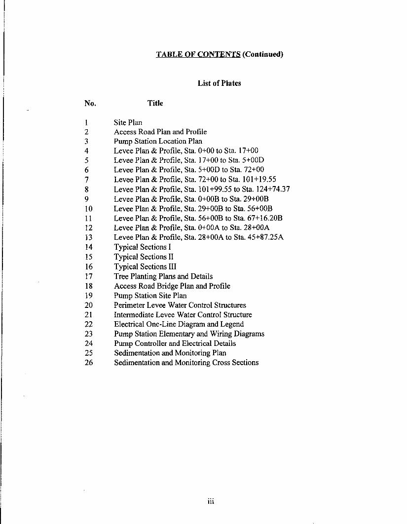
TABLE (Continued)
No. Title
1 2 3 4 5 6 7 8 9 10 11 12 13 14 15 16 17 18 19 20 21 22 23 24 25 26
List of Plates
Site Plan Access Road Plan and Profile Pump Station Location Plan Levee Plan & Profile, Sta. 0+00 to Sta. 17+00 Levee Plan & Profile, Sta. 17+00 to Sta. 5+00D Levee Plan & Profile, Sta. 5+00D to Sta. 72+00 Levee Plan & Profile, Sta. 72+00 to Sta. 101+19.55 Levee Plan & Profile, Sta. 101+99.55 to Sta. 124+74.37 Levee Plan & Profile, Sta. O+OOB to Sta. 29+00B Levee Plan & Profile, Sta. 29+00B to Sta. 56+00B Levee Plan & Profile, Sta. 56+00B to Sta. 67+16.20B Levee Plan & Profile, Sta. O+OOA to Sta. 28+00A Levee Plan & Profile, Sta. 28+00A to Sta. 45+87.25A Typical Sections I Typical Sections II Typical Sections III Tree Planting Plans and Details Access Road Bridge Plan and Profile Pump Station Site Plan Perimeter Levee Water Control Structures Intermediate Levee Water Control Structure Electrical One-Line Diagram and Legend Pump Station Elementary and Wiring Diagrams Pump Controller and Electrical Details Sedimentation and Monitoring Plan Sedimentation and Monitoring Cross Sections
.., 111

OPERATION AND MAINTENANCE MANUAL BAY ISLAND REHABILITATION AND ENHANCEMENT
UPPER MISSISSIPPI RIVER ENVIRONMENTAL MANAGEMENT PROGRAM
POOL 22, RIVER MILES 311 THROUGH 312 MARION COUNTY, MISSOURI
1. INTRODUCTION.
(1) This manual serves as a guide for the operation and maintenance of Bay Island Rehabilitation and Enhancement. It provides operation and maintenance instructions for the major features of this environmental management project. The instructions are consistent with the general procedures presented in the March 1990 Definite Project Report. This document is written for project and management personnel who are familiar with the project and does not contain detailed information which is common to site personnel or which is presented in other existing manuals or regulations.
(2) The intent of the operating instructions is to provide information which allows orderly and effkient use of the constructed features to meet project goals and objectives. The intent of the maintenance instructions is to present preventative maintenance information consisting of systematic inspections and subsequent corrective actions which should ensure long-term utilization of equipment and features. A timely preventative maintenance program reduces and virtually eliminates breakdown of essential equipment and prevents major damage to constructed features by early corrective action.
(3) This manual provides the general standards of maintenance and establishes an initial frequency of maintenance inspections which should ensure satisfactory project performance.
b. Use of Manual.
(1) This manual is divided into the following sections: Section 1: Introduction; Section 2: Historical Summary; Section 3: Description of Project Features; Section 4: Inspections; Section 5: Operation and Maintenance of Project Features; and Section 6: Performance Monitoring and Assessment.
(2) Sections 2 and 3 present historical summaries and descriptions of actual features constructed for this project. Section 4 includes project inspection procedures, and Section 5 presents operation and maintenance instructions for each project feature. Section 6 surnmarizes monitoring activities conducted through construction as well as an overview
1

of continued monitoring actions. Performance monitoring is considered necessary to properly evaluate effects of the constructed project features.
(3) The attached drawings have been included to provide general project “as- built” plans and typical sections.
2. HISTORICAL SUMMARY.
a. Authorization and Location.
(1) This project is authorized by the Supplemental Appropriations Act (Public Law 99-88) and Section 1103 of the Water Resources Development Act of 1986 (Public Law 99-662). The project was funded and constructed under this authorization by the U.S. Army Corps of Engineers, Rock Island District, in cooperation with the U.S. Fish and Wildlife Service (USFWS) and the Missouri Department of Conservation (MDOC).
(2) The Bay Island complex encompasses approximately 650 acres of aquatic, wetland, and terrestrial habitat. It is located in Pool 22 on the Missouri side of the Upper Mississippi River navigation channel between river miles (RM) 3 11 and 3 12, approximately 1 mile north of the city of Hannibal, Missouri.
. . . . b. ) v .
(1) Table 2.1 provides a summary of planning and construction activities.

w
TABLE 2.1 SUMMARY OF PLANNING AND CONSTRUCTION ACTIVITIES
Project
Phase
k-project
Design
Construction
Purpose
Identify and defme problems
and establish need of project
Quantify project objectives,
perform preliminary design, satisfy
NEPA and permit requirements,
develop performance evaluation
plan, obtain project approval for
construction.
Finalize plans and specifications,
obtain operation and maintenance
agreement, advertise and award
construction contract, construct
project.
Responsible
Agency
Corps/USFWS
Corps
corps
Item
Fact Sheet
Submitted to ASA
Approved by ASA
Definite Project Report
Draft
Final
Approved
NEPA Compliance
SHPO Concurrence
Public Review
FONSI for EA
Permits
Section 401
Section 404
Refuge Compatibility
Plans and Specifications
Final
Approved
Real Estate
O&M Agreement
Date
MAR 87
MAY 88
SEP 89
MAR 90
SEP 90
22 SEP 89
lRFEB90
23 MAR 90
06 OCT 89
23 MAR 90
12 JUN 89
DEC 90
FEB 91
DEC 90
Remarks
11 __
_-
_-
.-
Y
-.
-.
__
-_
--
Ref. App. A

P
TABLE 2.1 (Continued) SUMMARY OF PLANNING AND CONSTRUCTION ACTIVITIES
Project
Phase Purpose
Responsible WiGcant Events
Agency Item Date Remarks
Levee/Structures/Tree Planting
Awarded
Substantially Complete
JUL 91
NOV 94
Post-
Construction
Operate and maintain project. MDOC
Post-Flood Tree Planting
Advertised
Awarded
Substantially Complete
MAR 94
APR 94
NOV 94
Reference
Sections 4 and 5
Perform evaluation monitoring. corps Reference Section 6
Notes: I’ Assistant Secretary of the Army ” A FONSI was completed by both Corps and USFWS.

(2) Goals and objectives were formulated during the design phase. Table 2.2 provides a summary of project objectives.
TABLE 2.2 PROJECT GOALS, OBJECTIVES AND ENHANCEMENT POTENTIAL
Goal Objective Unit of
Measure Enhancement Potential
Existing Target
Enhance Wetland Provide controlled Acres 40 400 Habitat for Migratory water levels during Waterfowl waterfowl migration-
forested and non- forested
Increase mast tree dominance - forested wetland
Acres 4.9 36.9
Increase total wetland values for migratory waterfowl
Habitat ’ Suitability Indices &
Habitat Units
0.14 0.62 - 0.64
99.1 4205434.0
Note: ’ See Section 6.
(3) The project was designed by the Rock Island District, U.S. Army Corps of Engineers, in cooperation with the USF WS and the MDOC. Design considerations and investigations are presented in the Definite Project Report dated March 1990. The construction contract was supervised by the Rock Island District.
(4) The construction contract, number DACW25-91-C-0057, was awarded to Northwest Construction Corporation, Ellisville, Missouri, on 29 July 1991 in the amount of $1,265,475. This bid was approximately 11% above the Government Estimate.
(5) In July 1993, a flood of record on the Mississippi River resulted in flooding to the project just prior to its completion. Seeding of the project was the only remaining item to be completed. The major damage caused by the Great Flood of 1993 to the project was the inundation and subsequent loss of the mast tree plantings. The levees and structures were all overtopped and remained submerged until October 1993. In addition to scattered surface erosion, damages due to overtopping included loss of material along the Mississippi River side of the perimeter levee, minor riprap and choke stone displacement, sedimentation at the water control structures, and loss of granular surfacing
5

material on the access road. The pump control panel was also damaged by the flood. Modifications were made to the contract to repair the flood damage to the levee and structures. A new contract was awarded for the replanting of mast trees.
c. Actual Project Costs. The actual project costs are presented in Table 2.3. --s
TABLE 2.3 ACTUAL PROJECT COSTS
Item Desqiption Quantity IJIM u/P Amount
BAY ISLAND, MISSOURI HABITAT REHABILITATION AND ENHANCEMENT PROJECT (DACW25-91-C-0057)
oool Mobilization and Demobilization 1 LS S I3,060.00 $ 13,060.oO
0002 Clearing and Grubbing
DOOZA Areas Cleared by Previous Timber Clearing Contract 30 AC 2.330.30 69.909.00
DOO2B All Other Areas 28 AC 3.828.00 107,184.00
Do03 Embankment 46,000 CY 4.25 195,500.00
ooo4 Pump Station I LS 242,300.OO 242,300.OO
ooo5 Water Control Structures
DOOSA Perimeter Levee, North I Ls 135,405.oo 135,405.OO
DOOSB Perimeter Levee, South I LS 106.820.00 106,820.OO
000X Intermediate Levee 1 LS 72,2 15.00 72,215.OO
Do06 Access Road Bridge I LS 105,315.oo 105,315.OO
Do07 Granular Surfacing 1,650 TN 13.13 21,664.50
DO08 Stone Protection, Riprap 1,925 TN 28.14 54,169.50
Do09 Landscaping
DOO9A Planting Acorns 3 AC 1,083.OO 3,249.OO
MXJ9B Planting Seedling Trees I Ls I I ,285.OO I l-285.00
Planting Container Grown or Balled and Burlapped Stock I LS 32.495.00 32.49500
0010 Seeding 1 LS 37,550.oo 37.550.00
WII Excavation for Ditches in Excess of that Required for Adjacent Embankment
DOllA First 100 Cubic Yards 100 CY 8.17 817.00
DOIlB Over 100 Cubic Yards 3,000 CY 5.45 16,350.OO
Subtotal S 1 f25.288.00
6

TABLE 2.3 (Continued) ACTUAL PROJECT COSTS
tern
0012
0013
0014
0015
0015 A
Description
Temporary Field Office
Work to be Performed by the Missouri Rural Electric Cooperative Utility Company
Work to be Performed by the Burlington Northern Railroad for Land Access to the Site
Monthly Telephone Bills
First $500.00
Quantity U/M
I Ls
I LS
I Ls
500 DL
U/P Amount
Subtotal S I J25.288.00
18,200.OO I8,200.00
I2,790.00 I2.790.00
7Jl90.00 7,090.OO
752.00 752.00
0015 B
0016
0017
0018
0019
0020
0021
0022
0023
0024
a025
0026
0027
0028
0029
0030
Over f500.00
Provide Survey Information
Obtain Alternate Borrow
Adjust Estimated Quantity of Item 0003
Install 3/4” x 6” studs and place 3’ of 2” graded rock in sheet pile structure
Pumping outside of normal operating hours for the South River Drainage District
Initial Mowing and Watering
Additional Mowing
Additional Watering
Dewatering System, Replace Subgrade Material
Install 875 Tree Shelters
Bond Maintenance
Pump Station Repair
Remove Debris, Reshape Levee, Fill Low Spots, Clean StruUs.
Replace Granular Surface
Replace Riprap
900 DL 1~55.00 1,355.OO
I Ls 5285.82 5,38X82
4,500 CY 10.32 46,440.OO
4,500 CY 4.25 (-19.125.00)
I LS 595.07 595.07
1 Ls l,717.57 1,717.57
I LS 1.092.44 I,O92.44
2 EA 732.46 1.464.92
6 EA 1.339.33 8.035.98
I LS 9.483.65 9,483.65
I LS 7.498.43 7,498.43
I Ls 1,915.97 1,915.97
I LS 39,392.OO 39,392.OO
I Ls 44,400.OO 44,400.OO
720 TN 15.00 10,800.OO
75 TN 29.00 2,175.OO
Subtotal S 1.426.746.85
7

TABLE 2.3 (Continued) ACTUAL PROJECT COSTS
tern Description Quantity u/M U/P Amount
Subtotal S 1,426,746.85
0031 Levee Seeding 35 AC 1,950.oo 68,250.OO
0032 Pump Station Cleanup I LS 3,400.91 3,400.91
. . . . _ . . . . . . _ -.....--...-.... _.._ . . . . . . . . . . . . . . . . . . . . . . . . . . . . . . . . . . . . . . . . . . . . . . . . . . . _ . . . . . . . . . . . . . . . . . . . . . . . . . . . . _ . . . . . . . . . . . . _ . . . . . . . . . . . . . . . . . . . . . - . . . . ..............-.....-....-..-....--..........-....-.-.-. ! ...-. !.?!!!2?:?5. TOTAL COST (DACWX-91C-0057)
POST FLOOD TREE REPLANTING, BAY ISLAND (DACW25-94-C-0073)
0001 Planting Acorns 3 AC 446.00 $ I ,338.OO
0002 Planting Seedling Trees I LS 18,429.OO I8,429.00
0003 Tree Shelters I Stakes for Seedling Trees I LS 3,920.OO 3,920.OO
ooo4 Planting Container Grown or Balled and I LS 39.370.00 39.370.00 Burlapped Trees
TOTAL COST (DACW25-94-C-0073) S 63.057.00 . . . . . . ..-...-.. _ ..-...--...................................... _ . . . . . . . . . _ . . . . . . . . . . . . . . . . . . . . . . . . . . . . . . . . _ . . ..-.. _ . . . . . . . . . _ . . . . . . . . . __.._ . . ..__..-.. _ ._...................-....-..-........................-....-.. _ -.........................
TOTAL CONSTRUCTION
LANDS AND DAMAGES
PLANNING, ENGINEERING, AND DESIGN
CONSTRUCTION MANAGEMENT
6 1,561,454.76
I ,640.66
586,395.87
159,065.15
TOTAL PROJECT COSTS S 2,308,%X44
8

d. Proiect References. Table 2.4 summarizes related project references.
TABLE 2.4 PROJECT REFERENCES
Title
Upper Mississippi River System Environmental Management Program, Definite Project Report (R-8) with Integrated Environmental Assessment, Bay Island. Missouri, Rehabilitation and Enhancement, U.S. Army Corps of Engineers, Rock Island District
Date
Mar 90
Purpose
Provided planning, engineering, and sufftcient construction details of the selected plan for project approval purposes.
Construction As-Builts
Manufacturer’s Data (Shop Drawings)
Nov 95
Nov 95
Provides as-built construction drawings.
Provides detailed operation and maintenance instructions for specific pieces of equipment as recommended by the manufacturer.
9

3. DESCRIPTION OF PROJECT FEATURES.
a. Project Data. Table 3.1 presents a summary of project data.
TABLE 3.1 PROJECT DATA SUMMARY
Item Quantity U/M
Wetland Management Units Perimeter Levee Embankment Fill ~~gth
Top Width Top Elevation
Side Slopes
55,ooo 19,194 10 or I2 469.0 469.0 to 468.0
468.0 411
Cubic Yards Feet Feet MSL, station 0+00 to station 46+50 MSL, varies from station 46+50 to
station 121+00 and from station 67+17B to station 6+04B
MSL, station 121+00 to station 124+50 Horizontal : Vertical
Intermediate Levee Embankment Fill Length
Top Width Top Elevation Side Slopes
10,165 Cubic Yards 4,800 Feet 10 Feet 468.0 MSL 4:l Horizontal : Vertical
Pump Station Submersible Pump *rating Elevations
Unit Maximum Elevation Sump Floor Elevation
Electric Power Source Primary Supply Transformer Size secondary Supply Power Converter
Inflow Pipe
I 6,000 gpm at 10.1 TDH
466.0 MSL 453.0 MSL
7200 V. I phase 31.5 kVA, 1 phase IZOR40 V. I phase
30 hp, 3 ph= 24 RCP
Perimeter Levee Water Control Structures Concrete Weir Length Invert Elevation
Intermediate Levee Water Control Structures Concrete Weir Length Invert Elevation
54 Cubic Yards 20 Feet 462.0 MSL. South Unit 462.5 MSL, North Unit
40 Cubic Yards 6 Feet 463.0 MSL
Access Road Length Width
Tree Plantings Area
6,150 Feet IO Feet with crushed stone surface
30 Acres
10

b. General Descrintion. The Bay Island project consists of wetland enhancement by development of water level control and forest cover management. Water level control is provided by construction of low levee segments which are used to impound water during seasonal waterfowl migrations. Water is provided by a pump station, located along a river side channel. Forest cover management consists of thinning and planting to increase the quantity of mast-bearing tree species. A total of about 25 acres of bottom land forest, emergent wetland, and cropped ground has been converted to grass-covered levee. As proposed, 20 acres of bottom land forest will be selectively thinned to improve production. About 10 acres of cropland was planted to pin oak and pecan trees.
. c. Water Level Control Through WeBent Umt (WMU) . Construction . Over 400 acres of the Bay Island project area can be impounded by the constructed earthen levees and associated water control structures to create a 240-acre forested north WMU and a 165-acre non-forested south WMU as shown on plate 1.
(1) Water C-01 Plan. During impoundment, the water surface elevation in the north WMU will be 464.0 feet mean sea level (MSL) and the water surface elevation in the south unit will be 466.0 MSL. Table 3.2 shows the areas of incremental water depths for various flooding heights for each WMU. The selected operating water levels are those that maximize the area with water less than 2 feet deep. Migratory waterfowl, in particular dabbling ducks, require water depths of 12 to 18 inches for access to food plants. The proposed water surface elevations represent those elevations which will give the greatest areaI average of 12- to 18-inch depth with both management units. The selected water surface elevations represent maximum levels for design purposes; actual operation levels may be lower if desired.
The pump station for flooding the WMU is located in the south WMU. To flood the north WMU, water enters through the intermediate levee stoplog water control structure. The drainage ditch adjacent to the perimeter levee allows water to flow directly from the water source to the intermediate levee water control structure and then into the north WMU without flooding the south WMU. Both units gravity drain independently through separate perimeter levee stoplog water control structures into Clear Creek, allowing for completely independent operation (flooding and draining) of the two WMUs.
11

TABLE 3.2 WATER DEPTHS VERSUS HEIGHT
Top Acres < 1’ Acres 1‘ -2 * Acres 2'3' Acres 3.4’ Acres>4’ Total Acres Elevation Deep Deep D=P Deep Deep Flooded
462 0.3 0 0 0 0 0.3 463 9.3 0.3 0 0 0 9.6 464 9.3 9.3 0.3 0 0 18.9 465 35.0 9.3 9.3 0.3 0 53.9 466 34.9 35.0 9.3 9.3 0.3 88.8 467 30.2 34.9 35.0 9.3 9.6 119.0 468 31.0 30.2 34.9 35.0 18.9 150.0
Top Acres c 1’ Acres I’-2’ Acres 2’-3’ Acres 3’-4’ Acres > 4’ Total Acres Elevation Deep D*P Deep Deep Deep Flooded
462 9.8 0 0 0 0 9.8 463 29.4 9.8 0 0 0 39.2 464 29.5 29.4 9.8 0 0 68.7 465 35.3 29.5 29.4 9.8 0 104.0 466 35.0 35.3 29.5 29.4 9.8 139.0 467 29.0 35.0 35.3 29.5 39.2 168.0 468 30.0 29.0 35.0 35.3 68.7 198.0
(2) Water Sours. Ziegler Chute is the water source for flooding the units. To accommodate WMU management strategies, a minimum pumping capacity of 6,000 gpm is required. Because Ziegler Chute is a part of the Mississippi River, its water surface levels will fluctuate minimally and can easily supply water for a surface water intake pump. The average depth of Ziegler Chute in the vicinity of the pump station is 3 feet.
(3) &x&&&n. The pump station has been sized to fill the north WMU in 15 days. This is the site management filling criterion which requires the greatest pumping capacity. Pump station plans and details are shown on plates 3 and 19.
The pump station is provided with a 6,000 gpm submersible propeller-type pump. This pump has the capacity to fill the forested unit in 15 days and to fill both units in 23 days total. The pump is housed in a vandal-resistant cast-in-place housing. The intake entrance is equipped with a trash rack. Underground electrical power is provided to the site, and all
12

necessary electrical equipment is located on an overhead platform in the vicinity of the pump station, as shown on plates 22,23, and 24.
(4) Water Control Structures. Operation of the WMUs requires the use of three concrete stoplog water control structures (see plates 20 and 21). The perimeter levee water control structures are sized to preclude the need for an armored levee overflow section. The perimeter levee water control structures have four S-foot stoplog bays. The intermediate levee water control structure has two 3-foot stoplog bays. All of the water control structures have a steel grate deck to allow for vehicle passage overhead.
(5) Jevee &gJ&. To accommodate the water control plan, the minimum top elevation for the WMU perimeter and intermediate levee system is 468.0 MSL. This provides a minimum freeboard of 1.3 feet during filling operations.
From a flood protection standpoint, the perimeter levee provides slightly more than a 2- year level of protection. To minimize scour potential, the perimeter levee profile parallel to the Mississippi River is sloped upstream to provide for gradual overtopping during flood events greater than 2 years. Also, the water control structures are designed to allow sufficient inflow into the units such that head differential will be only 0.7 foot when overtopping does occur.
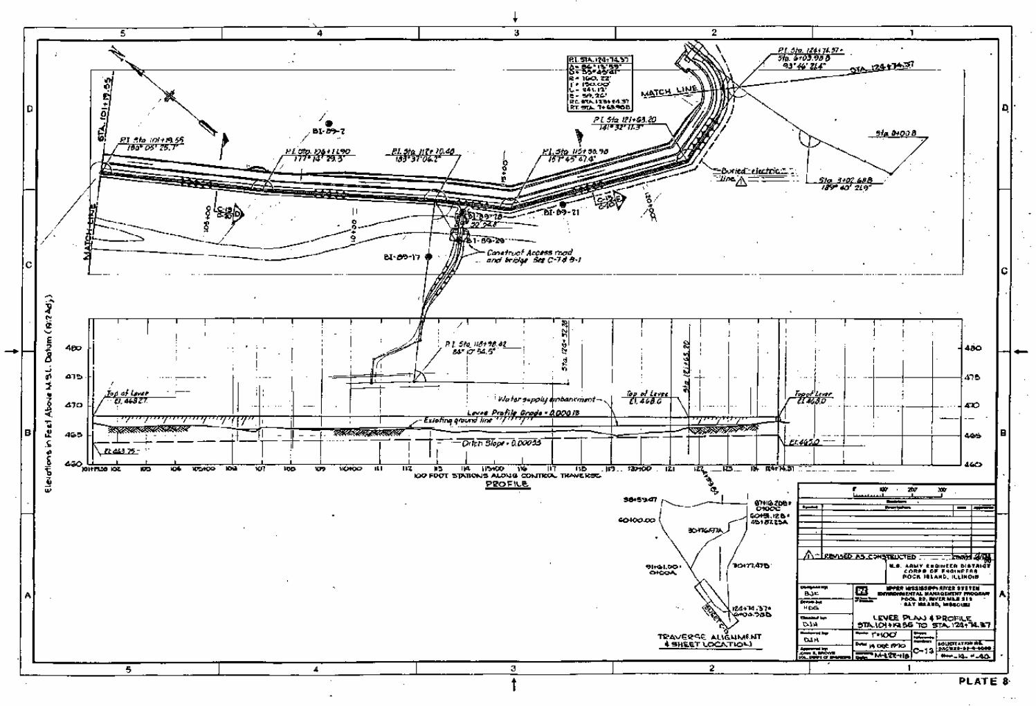
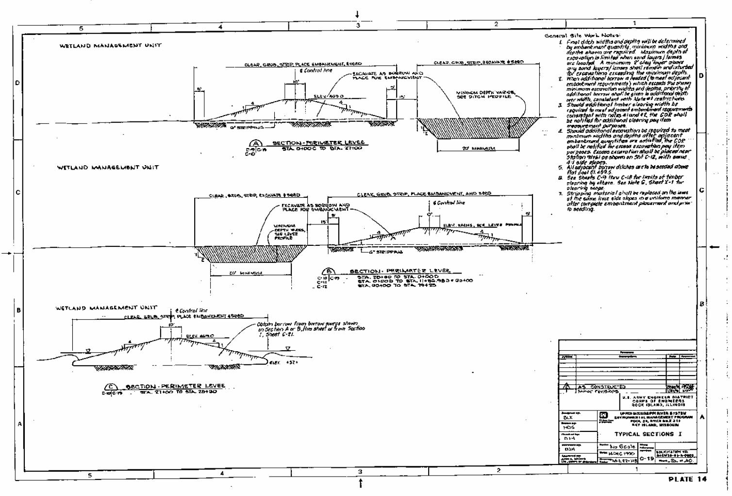
(6) Levee Borrow. Borrow for the perimeter and intermediate levees came from adjacent ditch excavations or was scraped from adjacent cropland as shown on plates 14 through 16. Plans and profiles are shown on plates 4 through 13. These ditches serve as an internal drainage system for the WMUs and facilitate the water control plan as described previously.
(7) Site Access. Access to the project is gained by a crushed stone access road. The majority of the eastern segment of the access road follows an existing access road alignment from the county road west of the project site to the west perimeter levee. The access road is shown on plates 2 and 7 through 8. The road is 10 feet wide and surfaced with 6 inches of crushed stone. The road is used by MDOC personnel for operation and maintenance activities and can be used by share croppers to access crop areas. The access road also facilitates delivery of materials for seeding and operation and maintenance of the pump station and structures.
A new prefab&-&i deck bridge with concrete abutments provides project access over Clear Creek. The span length is 42 feet and the deck width is 15 feet. The bridge carries a standard H20 loading designation. The bottom elevation of the bottom chord of the bridge is 464.0 MSL. This was designed to allow passage of a loo-year flow of Clear Creek plus the drainage outflow from the South River Drainage District (located immediately upstream of the project) with 1 foot of clearance (see plate 18).
Access to the site is controlled by MDOC to prevent public vehicular access to the refuge area and to minimize consequent disturbance.
13

d. Cover Manaqement. The mast tree planting project consisted of selectively thinning approximately 20 acres of forest area in the north WMU, within which 5 blocks of balled and burlapped pin oak trees were planted, amounting to approximately 4 acres. In the south WMU, 7 acres of pin oak tree seedlings and 3 acres of acorns were planted. These areas are shown on plate 17. State and Corps of Engineers foresters recommended the pin oak planting sites. In the north WMU, areas with the poorest existing stock and possessing the most mature pecan trees were selected for underplanting with the chosen mast specie. Sites possessing the highest natural elevations, thereby minimizing inundation periods, were selected for pin oak planting in the southern WMU. The planting scheme was 4 acres of balled and burlapped trees, 23 acres of seedlings, and 3 acres of acorns.
4. INSPECTIONS.
a. General.
(1) An active maintenance program is based on inspections and subsequent servicing, adjustment, or repair. The two main objectives of inspections are to: (1) ensure project serviceability by timely and thorough inspections, thereby avoiding or reducing maintenance costs, and (2) document the condition of the project as a baseline for consideration of rehabilitation for project damage resulting from a major storm or flood event.
(2) The two types of inspections for the project are: (1) Project Inspection by the Site Manager, and (2) Joint Inspection by the Site Manager and personnel from the U.S. Army Corps of Engineers, Rock Island District.
. . b. grniect mectlon bv Site Man- .
(1) The Project Inspection should be performed by the Site Manager or appropriate representative for the purpose of noting routing deficiencies and initiating corrective actions. This inspection will be performed at periods not exceeding 12 months and will follow inspection guidance presented in subsequent sections of this manual. It is suggested that the inspection be conducted every May, which is representative of after- spring flood conditions. Other Project Inspections should occur as necessary after high water events or as scheduled by the Site Manager.
(2) A Project Inspection checklist has been developed as presented in Appendix B. It is suggested that the Site Manager furnish a copy of the completed checklist to the U.S. Army Corps of Engineers, Rock Island District, ATTN: CENCR-OD-S, Clock Tower Building, P.O. Box 2004, Rock Island, Illinois 6 1204-2004, immediately following each Project Inspection.
14

. . c. Joint Insnectlon by Site Manaper a nd . U.S. Armv Corns of Enemee r8.
(1) Routine. A Joint Inspection by the Site Manager and the Corps of Engineers shall be made in accordance with ER 1130-2-339. The purpose of this inspection is to assure that adequate maintenance is being performed as presented in the Detailed Project Report and this manual. One exception to the maintenance requirements as found in the above stated regulation is in the mowing frequency (see section 5.b.(2) of this manual). This exception was mutually agreed upon by the Sponsor and the Corps of Engineers. The District Engineer or Authorized Representative should have access to all portions of the constructed project upon coordination with the Site Manager for this purpose.
(2) w. A Joint Inspection by the Site Manager and the Corps of Engineers should be formally requested by the Site Manager immediately following a specific storm or flood event which causes damage exceeding the annual operation comparison of pre- and post-Project Inspections by the Site Manager. The Joint Inspections will be the basis for determining maintenance responsibility and potential rehabilitation by the Corps of Engineers.
5. &TUOF .
a. M.
(1) This section presents operation and maintenance instructions for the major project features which were designed and constructed to minimize operation and maintenance requirements.
(2) Steps will be taken by the Site Manager to correct conditions disclosed by Project Inspections or Joint Inspections. Regular maintenance repair measures will be accomplished during the appropriate season as scheduled by the Site Manager to ensure structure serviceability. Appropriate advance measures will be taken to ensure the availability of adequate labor and materials to meet contingencies.
(3) Project feahues should be continuously maintained and operated to obtain maximum benefits. No encroachment or trespass which will adversely affect the efficient operation or maintenance of the project should be permitted upon the constructed features. No improvement should be passed over, under, or through the constructed features, nor should any excavation or construction be permitted within these features without prior approval by the Corps of Engineers, Rock Island District. Such improvements or alterations which are desirable and permissible should be constructed in accordance with standard engineering practice. Advice regarding the effect of proposed improvements or alterations on the functioning of the project and information concerning methods of
15

construction acceptable under standard engineering practice should be obtained from the District Engineer or, if otherwise obtained, should be submitted for approval. Drawings or prints showing improvements or alterations as finally constructed should be furnished to the District Engineer after completion of such work.
b. Perimeter and Intermediate Levees.
(a) During operational inundation periods, the levees should be inspected to be certain that:
(i) There are no indications of slides or sloughs developing;
(ii) Wave wash or scouring action is not occurring;
(iii) No low reaches of levee below design grade exist which may be overtopped;
(iv) No other conditions exist which might endanger the structure.
(b) Appropriate advance measures should be taken to ensure availability of adequate labor and materials to meet contingencies. Steps should be taken to control any condition which endangers the levee and to repair the damaged section. If additional riprap is needed to protect eroding banks, the material presented in Table 5.1, or equivalent material, should be used.
TABLE 5.1 RIPRAP REPLACEMENT MATERIAL (IOWA CLASS “D” RIPRAP)
Stone Weight Minimum Percent (Pounds) Larger Than
250 0 90 50 5 90
(2) Maintenance.
(a) The Site Manager should provide at all times such maintenance as may be necessary to ensure the serviceability of the levee in time of inundation. Measures
16

should be taken to promote the growth of sod, control burrowing animals, provide routine mowing (1 mowing per year) on the levees extending 5 feet horizontally from the toe of the levee, remove wild growth and drift deposits, and repair damage caused by erosion or other forces.
(b) Project inspections should be made by the Site Manager to ensure that the above maintenance measures are being effectively carried out and to be certain that:
(i) no unusual settlement, sloughing, or material loss of grade or levee cross section has taken place;
(ii) no caving has occurred on either the landside or the riverside of the levee which might affect the stability of the levee section;
(iii) no seepage, saturated areas, or sand boils are occurring;
(iv) no revetment work or riprap has been displaced, washed out, or removed;
(v) no action is being taken, such as burning grass and weeds during inappropriate seasons, which will retard or destroy the growth of sods;
(vi) the crown of the levee is shaped to drain readily;
(vii) there is no unauthorized grazing or vehicular traffic on the levee; and
(viii) encroachments are not being made on the levee which might endanger the structure or hinder its proper and efficient functioning during times of inundation.
(c) Such inspections should be made prior to the beginning of an inundation period, immediately following major high water periods, and otherwise at intervals necessary to ensure the best care of the levee or one time per year as stated in Section 6. Steps should be taken to correct conditions disclosed by such inspections. Regular maintenance repair measures should be accomplished during the appropriate season as scheduled by the Site Manager.
c. Water Control Structures.
(1) Operation.
(a) When the WMUs are in use or water levels of the Mississippi River rise with heavy sediment loads, the stoplogs in the perimeter water control structures should be
17

installed to prevent sediment from entering Bay Island. The stoplogs should remain in place until:
(i) heavy sediment flood water recedes;
(ii) the WMUs are not in use;
(iii) overtopping of the perimeter levee is anticipated. Overtopping occurs at an elevation of 468.0 at RM 3 11 .O. This elevation correlates to a river stage of 17.6 feet at the Hannibal Gage (RM 309.0). The Site Manager should note that the access bridge is submerged at an elevation of 466.0 (RM 3 11) or a stage of 15.6 feet at Hannibal.
(b) A stoplog lifting hook is furnished with the project for the installation and removal of the stoplogs. This tool is intended for use at all three of the structures and should be stored in a secure place to allow ready use when needed.
(2) Maintenance.
(a) The water control structures should be inspected immediately following a high water event to determine whether seepage is taking place along the lines of its contact with the embankment. Corrective action should be taken upon discovery of any adverse conditions at the structures.
(b) Project inspections of the control structures should be made by the Site Manager to be certain that:
(i) stoplogs, headwalls, staff gages, stoplog keepers steel rails posts and grating are in good operating condition;
(ii) inlet and outlet channels are open;
(iii) care is being exercised to prevent the accumulation of trash and debris near the structures; and
(iv) erosion is not occurring adjacent to the structure which might endanger its function.
(c) Steps should be taken to repair damage, replace missing or broken parts, or remedy adverse conditions disclosed by such inspections.
18
d. Interior Ditches.
(1) Operation. The interior ditches should be inspected immediately following major high water events. As soon as practicable after high water events, all snags and other debris should be removed from the ditches.
(2) Jl!laiHen~ce.
(a) Project inspections of the interior ditches should be made by the Site Manager to be certain that:
(i) the ditches are cleared of excessive debris, weed, and wild growth;
(ii) the ditches are not being restricted by the depositing of waste materials, building of unauthorized structures, or other encroachments;
(iii) banks are not being damaged by ram or wave wash and that no sloughing of banks has occurred.
(b) Steps should be taken to correct conditions disclosed by such inspections.
. e. w .
(1) Q~!x&xL To inundate the WMUs, the pump must be activated manually. The pump also must be deactivated manually once the desired interior water elevations are achieved. Pumping to maintain interior elevations during WMU operation also will be by manual activation/deactivation. To recover a OS-foot drop in interior water level, approximately 5 days of pumping will be required. Once initial flooding is completed (by November 1), total water level drops during the impoundment period (November through February) due to seepage, infiltration, and evaporation are not expected to exceed 0.5 foot. The pump station and water control structures are equipped with staff gages to easily determine water levels in the WMUs.
(2) m. Pump station inspections should be performed by the Site Manager. Steps should be taken to correct adverse conditions disclosed by such inspections. The pump station inspection should include the following:
(a) Strucm. Visually inspect all structural surfaces to discover any adverse conditions such as cracks, excessive corrosion, etc., of the concrete slab, steel sheet piling and elevated control platform. Conditions that may affect the integrity of the structure should be corrected as soon as practicable.
(b) $&JJ@&. All electrical controls and associated wiring should be examined closely and their overall condition assessed. Watertight connections should be
19

inspected for integrity. Any corroded, loose, or broken contacts should be cleaned tightened, and repaired as needed.
(i) Pump should be observed for indications of improper operation or damage. Avoid operation of pump during sump cavitation or ice conditions. The pump will automatically shut down through the control and status unit located in the electrical panel on high stator winding temperature, stator casing leakage, or high lower bearing temperature. Periodically check the sump for proper water depth, especially prior to extended operation. Mud in the sump may be a cause for cavitation during operation.
(ii) Site Manager should have an authorized representative conduct pump inspections and maintenance and repair work in accordance with, “Flygt PL-7050 Installation, Care, and Maintenance Manual.” Ancillary equipment such as cables, level sensors, starter and monitoring equipment should also be periodically inspected. Damaged components should be repaired or replaced by a qualified mechanic or electrician.
(d) Trash Racks. Site Manager should check for trash accumulation at racks and clear as necessary. Should operating conditions or observations indicate trouble is developing and operating conditions will permit, inspections should be performed to investigate general condition.
(e) b. Site Manager should check for sedimentation in the sump of the pump station. Accumulated sediments in the sump may interfere with the proper operation of the pump and should he cleaned out prior to use of the pump.
f. Tree PlantinT.
(1) Qp&. Specific operation requirements will be performed as determined by the Site Manager. Survival and growth of planted trees will be monitored by the Rock Island District for 5 years by periodically inspecting the planting sites. Remedial actions shall be taken by the Site Manager as necessary to ensure tree survival. The Site Manager should keep records of maintenance mowing, herbicide application, as well as record of inspections and any corrective actions taken to ensure survival. These records should be kept for a minimum of 5 years.
(2) lvlaintenance. Vegetation between planted trees should be controlled for a minimum of 2 growing seasons by either mowing or herbicide application. Vegetation between the planted rows should not be allowed to exceed a height of 1 foot during this maintenance period.
20

6. PERFORMANCE MONITORING AND ASSESSMENT .
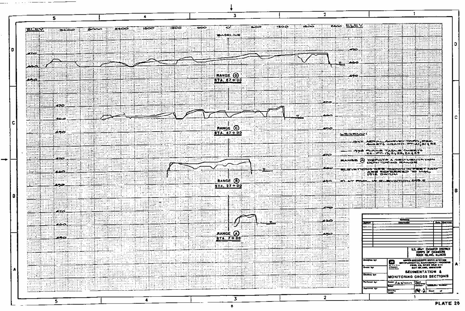
a. General. The purpose of this section is to summarize monitoring and data collection aspects of the project. Table 6.1 presents the principal types, purposes and responsibility of monitoring and data collection. Table 6.2 summarizes actual monitoring and data parameters grouped by project phase, responsible agency, and data collection intervals. Changes to the monitoring plan should be coordinated with the USFWS, the MDOC, and the Corps of Engineers.
. b. Post-Constructurn . Table 6.3 presents the post-construction evaluation plan. The monitoring parameters were developed to measure the effectiveness of the stated goals. The Site Manager should follow Table 6.3, as shown, to make annual field observations. These observations are summarized in checklist form in Appendix B. The annual field observations and the quantitative monitoring parameters will form the basis of project evaluation.
21

TABLE 6.1 MONITORING AND PERFORMANCE EVALUATION PLAN
Type of Activity Purpose Responsibility Instructions
Pre-Project Monitoring
Baseline Monitoring and Data Collection for Design
Construction Monitoring
Performance Evaluation Monitoring
Analysis of Biological Responses
Establish need of proposed project features
Establish baseline monitoring consistent with goals and objectives and meet specific requirements
Continue monitoring, assess construction impacts, and meet permit requirements
Continue monitoring and assess performance of project relative to goal and objectives
Evaluate predictions and assumptions made during initial WHAG analysis
Sponsor __
Corps of Engineers See plates 2.5 and 26
Corps of Engineers Included in construction contract documents
Sponsor (field observations)
Table 6.2
Corps of Engineers (quantitative)
Table 6.3
USFWS I.1
’ Annual waterfowl census data will be obtained from the USFWS to determine waterfowl response to the project.
22

TABLE 6.2 ANNUAL POST-CONSTRUCTION FIELD OBSERVATIONS I’
Goals Objective Unit of Measure Enhancement
Feature Field Observation
Enhance Wetland Habitat for Migratory Waterfow I
Provide controlled water Acres Wetland Presence of waterfowl levels during waterfowl Management migration - forested and Units - forested non-forested and non-forested
Increase mast tree Acres Mast tree plantings Survival of plantings dominance - forested wetland
Increase total wetland values for migratory waterfowl
Habitat Suitability Indices & Habitat Units
All Annual presence of waterfowl
u To be submitted to the Corps of Engineers by the USFWS with annual management report for Cooperative Agreement Lands.
TABLE 6.3 POST-CONSTRUCTION QUANTITATIVE MEASUREMENTS
I Unit of Enhancement Monitoring Gnals Obiective Measure Feature Monitorine Plan Intervals (vearsj
Enhance Wetland Habitat for Migratory Waterfowl
Provide controlled Acres Wetland Perform Area1 5 I’ water levels during Management Surveys waterfowl Units - forested migration - forested and non-forested and non-forested
Increase mast tree Acres Mast tree Timber Inventory 10 dominance - plantings forested wetland
Increase total Habitat All WHAG analysis 1, 15,50 wetland values for Suitability migratory Indices & waterfowl Habitat Units
’ First monitoring activity to occur in the first year after construction.
23