operation and maintenance manual - … g200, g400 epa certified wood burning furnaces operation and...
TRANSCRIPT

G100, G200, G400EPA Certified Wood Burning Furnaces
OPERATION AND MAINTENANCE MANUAL
Model:
By SteelTech Inc.Version 2
Serial No.:UL 2523-2009CAN/CSA B366.1-2011

2
heatmasterss.com 3
ContentsWarranty and Safety
Warranty Registration & Delivery Form . . . . Front InsertWarranty Details . . . . . . . . . . . . . . . . . . . . . . . . . . . . . 4Water Treatment And Testing . . . . . . . . . . . . . . . . . . . 5Safety Precautions. . . . . . . . . . . . . . . . . . . . . . . . . . . . 6Cautionary Markings. . . . . . . . . . . . . . . . . . . . . . . . . . 7
Furnace Installation Guide
Specifications . . . . . . . . . . . . . . . . . . . . . . . . . . . . . . . 8Location . . . . . . . . . . . . . . . . . . . . . . . . . . . . . . . . . . . 8Clearances To Combustibles. . . . . . . . . . . . . . . . . . . . 8Furnace Foundation . . . . . . . . . . . . . . . . . . . . . . . . . . 9Trench . . . . . . . . . . . . . . . . . . . . . . . . . . . . . . . . . . . . . 9Indoor Installation . . . . . . . . . . . . . . . . . . . . . . . . . . . 10Wiring And Hydronic Lines . . . . . . . . . . . . . . . . . . . . 12
Operating The Furnace
Filling The Furnace With Water . . . . . . . . . . . . . . . . . 16Firing The Furnace. . . . . . . . . . . . . . . . . . . . . . . . . . . 16Wood Quality, Testing and Storage . . . . . . . . . . . . . 17Loading The Furnace . . . . . . . . . . . . . . . . . . . . . . . . 18Operating A Gasification Furnace . . . . . . . . . . . . . . 19Controls And Safety Devices . . . . . . . . . . . . . . . . . . . 20How a Gasification Outdoor Furnace Works. . . . . . . 22
Care And Maintenance . . . . . . . . . . . . . . . . . . . . . . 23
Troubleshooting
Troubleshooting To Ensure Proper Burning And Air Flow . . . . . . . . . . . . . . . . . . . . . . . . 24Electrical Troubleshooting . . . . . . . . . . . . . . . . . . . . . 27
G100 And G200 Electrical Schematic . . . . . . . . . . . . 29G400 Electrical Schematic. . . . . . . . . . . . . . . . . . . . . 30Instructions for Editing Control Settings . . . . . . . . . . . 31
RETAIN THIS MANUAL FOR FUTURE REFERENCE
DO NOT THROW AWAY
CANADASteelTech Inc.
Box 158Winkler Mb. R6W 4A5
CanadaPh. (204) 325-9792 Fax (204) 325-9803
USASteelTech Inc.
Box 373Walhalla Nd 58282Ph. (877) 325-9792
Fax (204) 325-325-9803

4
LIMITED WARRANTYSteelTech Inc. warrants to the original owner of the G Series outdoor furnace that it is free from defects in workmanship and material, which could cause a leak or malfunction of the firebox or water jacket, and against corrosion (if the instructions in the owners manual for water treatment and maintenance are followed) for the life of the furnace toward the purchase of a new HeatMasterSS furnace, in the following pro-rated schedule.
Warranty schedule: coverage in the initial 5 years is 100%• Year 6-7 is 50%
• Year 8-9 is 40%
• Year 10-15 is 30%
• Year 16-Life is 10%
In addition, all steel components including housing, legs, etc. have a pro-rated warranty for a period of 10 years with coverage reducing by 10% per year. All firebrick used in the furnace is not warranted. Any parts not manufactured by SteelTech Inc., that are used on the furnace – such as thermostats, limit switches, pumps, heat exchangers – carry their own manufacturer’s warranty. SteelTech Inc. will not be liable for the cost of shipping, replacement or repair of these parts.
If warranty requires removing or replacing of the furnace or a part on the furnace, Steel-Tech Inc. is not responsible for the cost of plumbing, replacement of antifreeze or water treatment, shipping cost or any other cost other than the replacement component or
furnace. SteelTech Inc. always has the right to decide if a part or furnace will be repaired or replaced and will not be liable for any cost not authorized by a SteelTech Inc representative.
SteelTech Inc. does not warranty any damage caused due to negligence and deterioration due to lack of proper ongoing maintenance, physical damage caused by abuse or freeze up, power surges or unauthorized work or modifications to the furnace.
SteelTech Inc. is not liable for any damage or cost which may occur from or during the operation of the furnace or damage incurred due to any heating system failure. The purchaser assumes all responsibility for the care, maintenance and safe operation the furnace including adding of approved boiler treatment or water. SteelTech Inc does not warrant door gaskets, exterior paint or finish.
To qualify for warranty all instructions must be followed in operator’s manual, water must be tested and maintained a minimum of once per year, and warranty registration must be on file at SteelTech Inc Ind. within 30 days of purchase along with a copy of the original invoice. No warranty can be approved unless the warranty registration and water test verifications are on file at SteelTech Inc.’s office.
The warranty can be violated by operating the furnace in a manner inconsistent with the owner’s manual
SteelTech Inc. reserves the right to change conditions of warranty at any time.

heatmasterss.com 5
WATER TREATMENT AND TESTING
Water Treatment PolicyTo qualify for warranty, water must be tested a minimum of once per year and water treatment added when necessary.
To take a water sample:
1. Locate your water sample bottle, mailing carton and mailing label provided to you by your dealer.
2. Open the boiler drain located at the bottom of the rear of the furnace for 10-15 seconds or until the water runs clear. CAUTION: Water is hot! Use extreme care or a bucket to run water into and let cool before collecting sample.
3. Fill one of the test bottles at least 1/2 to 2/3 full.
4. Fill out the mailing label provided with the test bottle completely, including your email address, the model number and serial number of your furnace. Make sure to note if the furnace water contains any antifreeze or additional chemicals.
5. Attach top part of label to sample bottle and bottom part to outside of mailing tube. Place bottle in tube.
6. Mail to our testing lab. Results can take up to 4 weeks to receive and up to 8 weeks if no email address is on hand at HeatMasterSS.
You will receive a water test report outlining what must be done (if anything). If any action is necessary, take another sample and mail it to our test lab again to verify the recommended changes have been made.
Add the water treatment through the fill pipe located at the top of the furnace when initially filling the furnace with water or after testing, if needed. Ensure that all drains are closed. It is recommended that water treatment be added at a 1:200 ratio when initially firing the furnace and 1:300 after that. Additional treatment may have to be added for water with more severe properties or for systems with more chemically demanding requirements.
Recommended operating levels are as follows:Conductivity: 100 - 4000 ppm
pH: 8.5 – 10. 5
Nitrates: no less than 730 ppm
Test Parameters and What They MeanConductivity
Conductivity is a measurement of minerals in your furnace water. While it is common to have minerals in water, in excess minerals can cause many problems in hydronic systems including scaling and corrosion.
pH
pH is measurement of alkalinity (hard or soft water). For outdoor furnace water and the water treatment used in outdoor furnaces it is better to have your water a little harder than softer (recommended pH range is 8.5-10) as the active ingredients in the water treatment neutralize harder water easier than softer water
Nitrates
Nitrates tested for are a measurement of how much water treatment is in the water. Nitrates measured are active units of water treatment available to neutralize harmful elements in your furnace water. Nitrates also act to neutralize harmful bacteria that may build up in the furnace water over time.
Glycol
Inhibited glycol provides anti-corrosion elements and freeze protection for outdoor furnaces and is compatible with Outdoor Furnace Water Treatment. Because outdoor furnaces are open to the atmosphere systems and will have fresh water added occasionally, oxygen is always entering the system and will break down the glycol over time to create glycolic acid which will harm your furnace system. When this happens you will be required to drain and flush your furnace system.
It is always suggested to use 100% virgin glycol instead of recycled glycol as it will break down much sooner and create glycolic acid.

6
SAFETY PRECAUTIONSRead and understand all precautions before operating the furnace.
This wood heater needs periodic inspection and repair for proper operation. It is against federal regulations to operate this wood heater in a manner inconsistent with operating instructions in this manual.
Save these instructions. Retain this manual as long as you own your G SERIES outdoor furnace. Carefully read and follow these directions.
DANGERDo not start fire with or burn garbage, gasoline, naptha, engine oil or other inappropriate materials. Only competent persons with a sound understanding of this heating method should operate this furnace. Improper firing could result in personal injury and/or damage to the unit and void warranty.
ATTENTION• BURN WOOD ONLY. LOAD FUEL CAREFULLY OR
DAMAGE MAY RESULT
• The person(s) operating this furnace must comply with all applicable local and state laws or other requirements,
• The person(s) operating this furnace are responsible to run it in such a way so that it does not cause a public or private nuisance. Consult with local authorities prior to installation to adhere to local laws and ordinances.
• DO NOT OVERFIRE THIS HEATER. Attempts to achieve heat output rates that exceed the heater design specifications can result in permanent damage to the heater.
WARNING• All installations and operations of your G SERIES
product must follow state, provincial, and local laws pertaining to operations, wiring, plumbing and building codes.
• All models operate at atmospheric pressure. DO NOT obstruct, block or plug the overflow vent tube in any way, which is located on top of the boiler.
• When installing the furnace, the chimney should never be connected to a chimney flue serving another appliance
• Do not operate furnace in event of power failure
• Use caution when opening firebox and ash cleaning doors. Push by-pass rod on front of furnace and slowly crack door open for at least 20 seconds before opening door.
• Risk of fire:
– Do not operate with fuel loading or ash removal doors open.
– Do not store fuel or other combustible material within marked installation clearances
– Inspect and clean flues and chimney regularly
CAUTION• Do not start or operate furnace without checking
heating fluid. Furnace must be filled until heating fluid comes out of vent pipe on the top of the furnace.
• Check for buried cables and utility lines before digging the trench to your furnace.
• For safety and proper temperature control keep all doors closed during operation.
• Hot Surfaces: Keep children away. Do not touch during operation.

heatmasterss.com 7
Cautionary Markings
Images on this page not to scale

8
FURNACE INSTALLATION GUIDEInstallation should be performed by a qualified installer and will comply with all requirements of the agency having jurisdiction.
G100 G200 G400
Max BTU Output 120,000 BTU/hr 210,000 BTU/hr 350,000 BTU/hrHeat Output (8 Hour Burn) 47,772 BTU/hr 111,315 BTU/hr 180,409 BTU/hrFurnace Size (W x L x H) 36 x 55 x 76 48 x 67 x 82 49 x 78 x 88Furnace Weight 1300 lbs 2400 lbs 3000 lbsFirebox Dimensions (W x L x H) 18 x 18 x 33 27 x 28 x 37 29 x 40 x 42Chimney Size 6” 6” 8”Water Capacity 100 gallons 195 gallons 250 gallons8 Hour Average Efficiency Using Higher Heating Value of Wood
75.8% 79.0% 74.8%
LOCATIONWhere you install the furnace will have an affect on the efficiency of your furnace. Alt-hough the furnace is very well insulated, installing the furnace outdoors will mean some heat loss at the furnace. The furnace will have less heat loss when installed indoors away from the elements that can cause heat loss.
• Maintain adequate clearance of buildings and combustibles.
• Pile and store wood under shelter.
• Do not place or store wood within stove installation clearances or within the space required for charging and ash removal.
• For indoor installations where fans are used in the fuel storage area they should be installed so as to not create any negative pressure in the room where your G SERIES furnace is burning
• Contact all governing authorities in your area prior to installation.
• When choosing the location of your furnace you should consider prevailing wind direction, distance from home and wood storage for refueling.
• Give consideration for any effect on your neighbors.
CLEARANCES TO COMBUSTIBLESWhether installing your G SERIES furnace inside a building or outside the following clearances to combustibles must always be followed or damage and personal injury may result:
Minimum Clearance to CombustiblesFurnace Roof to Ceiling (Indoor Installations)
6”
Side Walls & Rear 6”
Front (Loading door) 24”
heatmasterss.com 9
FURNACE FOUNDATION• Footprint dimensions are in the illustration to the
right.
• Inspect the ground conditions that you intend to install your furnace on.
• A cement pad of 4-6” in thickness should be used. Cement pads should be a little bigger than the actual furnace. You can also include about a 4’ extra length front and back so you have a solid working area.
• The furnace can also be placed on 4 cement blocks not less than 6” wide X 10” long and 3” thick. Place your blocks so the legs will stand on the center of the blocks.
• The furnace may be installed on a combustible floor provided a noncombustible material such as metal or masonry liner is used in the following areas:
– Underneath the furnace
– At least 16“ in front of the furnace and 8” on each side of the firebox and lower combustion chamber doors.
TRENCHSteelTech Inc recommends the trench to be 24” to 36” deep and wide enough to install your water lines. If possible, have a gradual slope in your trench to allow drainage away from your lines and out of the trench bottom.
Most insulated underground pipe has room for electrical wire in it. If it does not, place electrical supply in bottom of trench and cover with 6 inches of dirt.
A minimum of R8 insulation value is recommended and a water tight vapor barrier such as PVC pipe or drain tile to encase your insulation is a must.
NOTE: If you are installing your water lines under an area where vehicles will cross, you should increase your depth of the trench and use a schedule pipe over your lines to reduce the pressure generated on the lines.
50.125”
44.3” 21”
58.44”
48” concretework space(optional)
48” concretework space(optional)
60.625”
45.69” 21.875”
69.69”
48” concretework space(optional)
48” concretework space(optional)
36.25 “
29.625”
8.625”
44.94”
48” concretework space(optional)
48” concretework space(optional)
G100
G200
G400

10
INDOOR INSTALLATIONIMPORTANT: Although these furnaces are approved for indoor installation, we do not recommend that they be installed in a home.
IMPORTANT: A fire may be caused by the following:
• Improper installation. To reduce the risk of fire, follow all local codes and these installation instructions carefully.
• Storing flammables in the same room as the furnace or wood fuel.
• Not carefully cleaning ash and embers from around the furnace area after loading or cleaning
ATTENTION: When installing the furnace in a building, always make sure that smoke and CO detectors are properly installed in the same area as the furnace.
Outside combustion air may be necessary if:
• The furnace does not draw steady, smells, rolls out smoke, is burning poorly or back drafts or if any of these symptoms are alleviated by opening a window.
• The building is equipped with a well-sealed vapor barrier and tight fitting windows and/or has any powered devices that exhaust house air.
• There is excessive condensation on windows in the winter.
• A ventilation system is installed in the house.
ChimneyNote: Incorrect chimney installation will void the warranty.
The chimney on your G Series outdoor furnace is a stainless steel double wall insulated chimney. When installing the furnace, the chimney should never be connected to a chimney flue serving another appliance. Make sure chimney, flue pipe and draft inducer fan stay clean and in good condition at all times.
The top of the chimney must extend at least 3.0 feet above the highest point where it exits the roof and be at least 2.0 feet taller than any point of the roof within 10.0 feet. For a new chimney, use an insulated stainless steel system that conforms to type HT (High Temperature) requirements of UL 103 and ULC-S629 and complies with the requirements of Chapter 11
of NFPA 211, Standard for Chimneys, Fireplaces, Vents and Solid Fuel Burning Appliances in the USA or CSA B365 Installation Code for Solid Fuel Burning Appliances and Equipment in Canada.
The recommended chimney and adapter collar is listed below.
This is a forced air furnace but it is important that the chimney has good draft to further eliminate any smoke issues.
Note that using a smaller chimney may cause smoke issues and using a larger chimney may negatively affect furnace performance.
ATTENTION: CLEANING OF THE HEAT EXCHANGER, FLUE PIPE, CHIMNEY AND DRAFT INDUCER IS ESPECIALLY IMPORTANT AT THE END OF THE HEATING SEASON TO MINIMIZE CORROSION DURING THE SUMMER MONTHS CAUSED BY ACCUMULATED ASH.
Chimney InstallationATTENTION: Before installing, check with local building codes for information regarding chimney height and distances to adjacent buildings, etc. You may need to obtain a building permit for installation of this appliance or the chimney.
We recommend that chimney installed on our products be installed by professionals who are certified in the USA by NFI (National Fireplace Institute) or in Canada by WETT (Wood Energy Technology Transfer).
Draft problems may occur because of incorrect chimney installation.
Make sure to follow these simple rules to ensure proper performance and safety.
1. The chimney must be connected using a minimum double wall stainless steel chimney and connecter.
2. Use only components intended for the brand and model of chimney you are using. Never substitute parts from other chimney brands or fabricate your own components.
Furnace Chimney SizeG100 6”G200 6”
G400 8”

heatmasterss.com 11
3. To be safe and effective, the chimney must be installed exactly in accordance with the manufacturer’s instructions.
4. Use a direct exit whenever possible. A vertical exit with no elbows is always the safest and most trouble free installation.
5. Maximum chimney installation height is 15 ft.
6. Maximum horizontal installation from furnace to exhaust exit is 3 ft.
7. Maximum 8 ft. run from elbow to elbow but keep as short as possible.
8. Never use an elbow with a greater than 30 degree bend. 45 degree elbows and tees cannot be used.
9. Elbows should never be installed in floor joists or roof and attic entries.
10. Shields should be used whenever going through floors, attics and roofs to keep the wood and insulation from getting too hot and possibly catching fire.
11. Make sure to follow local building codes.
Roof Penetrations and Clearances
The basic rule is this: the top of the chimney must clear the roof penetration point (the upper edge) by at least 3 feet and must clear anything within a 10 foot radius by at least 2 feet. This includes: the peak of the house, parapet, dormer, chimney, or spire. See diagram below.
If the chimney terminates beyond 10 feet from the ridge of the roof it must clear the upper penetration of the roof by 3 feet. Notice that the flue still terminates 2 feet above the roof at the 10 foot perimeter:
Combustion AirFireplaces, other furnaces, clothes dryers, exhaust fans, and other appliances all draw air from the room in which they are located. Your G Series furnace adds to that draw, making it important to ensure there is an adequate source of fresh air to offset these demands. Otherwise, a negative pressure may be created in the room and starve combustion in the furnace.
1. Determine the volume of space (cubic feet) in the room. Include in the calculation adjacent rooms and areas not closed off by doors.
Volume (CF) = Length (ft) x Width (ft) x Height (ft)
2. Determine the air input requirements of all appliances in the space. Add the BTU output of all appliances and round the total to the nearest 1000 BTU per hour. Your G Series Furnace requires 85 CFM (cubic feet/minute).
3. Determine whether the space is ‘confined’ or ‘unconfined’ by dividing the total volume of the room by the total input requirements for all appliances in the room.
a. If the result is equal to or greater than 50 CF/1000 BTU per hour, then consider the space ‘unconfined.’
b. If the result is less than 50 CF/1000 BTU per hour, then consider the space ‘confined.’
4. For an ‘unconfined’ space in a conventionally constructed building, the fresh air infiltration through cracks around windows and doors NORMALLY provides adequate air for combustion and ventilation, and therefore no additional make up air is required.
5. For a ‘confined’ space or an ‘unconfined’ space in a building with unusually tight construction, an additional source of make up air is required. Please consult an HVAC professional to determine the best way to supply make up air for this type of installation.
Important: The furnace room must never be in a negative pressure condition. Negative pressure could result in smoke in the room.
12
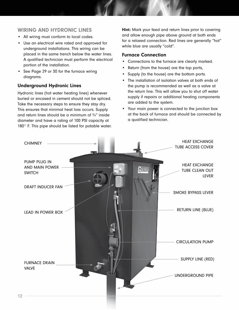
WIRING AND HYDRONIC LINES• All wiring must conform to local codes.
• Use an electrical wire rated and approved for underground installations. This wiring can be placed in the same trench below the water lines. A qualified technician must perform the electrical portion of the installation.
• See Page 29 or 30 for the furnace wiring diagrams.
Underground Hydronic LinesHydronic lines (hot water heating lines) whenever buried or encased in cement should not be spliced. Take the necessary steps to ensure they stay dry. This ensures that minimal heat loss occurs. Supply and return lines should be a minimum of ¾” inside diameter and have a rating of 100 PSI capacity at 180° F. This pipe should be listed for potable water.
Hint: Mark your feed and return lines prior to covering and allow enough pipe above ground at both ends for a relaxed connection. Red lines are generally “hot” while blue are usually “cold”.
Furnace Connection• Connections to the furnace are clearly marked.
• Return (from the house) are the top ports,
• Supply (to the house) are the bottom ports.
• The installation of isolation valves at both ends of the pump is recommended as well as a valve at the return line. This will allow you to shut off water supply if repairs or additional heating components are added to the system.
• Your main power is connected to the junction box at the back of furnace and should be connected by a qualified technician.
CHIMNEY
PUMP PLUG IN AND MAIN POWER SWITCH
DRAFT INDUCER FAN
LEAD IN POWER BOX
FURNACE DRAIN VALVE
HEAT EXCHANGE TUBE ACCESS COVER
SMOKE BYPASS LEVER
HEAT EXCHANGE TUBE CLEAN OUT
LEVER
RETURN LINE (BLUE)
CIRCULATION PUMP
SUPPLY LINE (RED)
UNDERGROUND PIPE

heatmasterss.com 13
Building ConnectionsA hole large enough to accommodate the water lines, insulation and PVC piping through the wall is important. Attention to sealing this point on both sides is also important.
System Flow RatesBecause of the efficiency in which your G Series furnace transfers heat into the water, it is important that enough water flow is present in the system. If there is not enough water flow, the water around the heat exchange tubes may boil while water in other parts of the tank are cool. It may be necessary to install a recirculation pump on an unused set of lines to make sure there is enough flow in the furnace to keep this from happening.
The following are required flow rates:
• G100 – 8 GPM (one typical building circuit)
• G200 – 16 GPM (two typical building circuits or one building circuit and a mixing pump on the back of the furnace)
• G400 – 25 GPM (four typical building circuits. If less than four, a mixing pump should be installed at the back of the furnace)
• A typical building circuit would provide 6 – 8 GPM
Interior ConnectionsYou may require either a water-to-water (tube and shell or plate) or a water-to-air exchanger (rad) to transfer heat energy from the hot water your furnace has produced. Your plumber or dealer can design and install a system to best fit your needs. The fol-lowing are examples of basic interior connections. Your dealer carries the necessary parts for installation.
It is important to note that when installing your piping system in your building that you should avoid installation methods that cause too great a restriction in the piping system. Examples of this are reducing pipe size, an excessive amount of joints and elbows, etc.
This may build up enough pressure to damage your piping, heat exchangers or other parts of your furnace. It is also important to install air bleed valves at high points in the system to avoid air lock, especially if these points are higher than the furnace. Air lock can restrict system flow which will restrict the amount of BTU’s available to your building and can cause your furnace to overheat or stratify so that cold water is sent to your building.
DISCLAIMER: The following information in the interior connections are examples and suggestions only. When installing a furnace and its parts it is best to consult your local dealer or a qualified technician.
Recirculation pump

14
Water-To-Water Heat ExchangersTo maintain pressure in an existing boiler system while using an outdoor furnace a water-to-water heat exchanger is used. The water-to-water exchanger is installed in-line on the supply side of the existing pressurized boiler system.
Flat Plate Exchanger For Pressurized Boiler SystemsFlat plate exchanger systems that are used with pressurized systems such as in floor heating systems help to heat the water going in to the pressurized system while keeping the two systems separate. Because an outdoor furnace is an open system (not pressurized) and the system tied in to in this type of application is pressurized it allows both systems to stay the same while being operational.
The water supplied by the outdoor furnace will heat the water in the pressurized system while the present heat source in the pressurized system (such as a boiler) can be used as a back up heat source in case of emergency or need for additional heat.
When connecting the furnace to an existing pressurized boiler system:
• The furnace must not be installed so that it interferes with normal heat delivery of the existing boiler system
• The furnace must be installed without affecting the operation of the electrical and mechanical safety controls of the original boiler
• Provide for a changeover from one fuel to the other without requiring manual adjustment of any controls or components other than the thermostats.
• Have provisions for preventing, or adequate water capacity within the boiler to prevent damage from loss of circulation due to electrical power failure.
• Be installed without changing the function of the controls or rewiring the original boiler. A wiring interconnection is permitted. The electrical system of both boilers shall be powered from a single branch circuit without exception.
Boiler Safety• Operate the boiler periodically to ensure that it will
operate satisfactorily when needed.
• Do not relocate or bypass any of the safety controls in the original boiler installation
• The operation of the boiler must be verified for acceptable operation before and after installation of the add-on appliance by a gas fitter who is recognized by the regulatory authority
• Do not connect to any chimney or vent serving a gas appliance
Installation should comply with requirements of CAN/CSA-B365, and changes to the installation should comply with CSA B139 (for oil-fired boilers), C22.1 (for electric boilers), or CAN/CSA B149.2 (for gas fired boilers).
Boiler Diagram

heatmasterss.com 15
Domestic Hot WaterFlat plate exchanger systems used to pre-heat domestic water tanks are generally more reactive to hot water demands then tube and shell systems. However tube and shell ex-changers hold up better when hard water is present.
Forced Air Furnace (Water-To-Air Exchanger)The water-to-air heat exchanger must be mounted so that air blows through the fins (coils). The exchanger should be mounted below the A/C coil if possible. The ex-changer should be sized to fit existing duct work and should produce about as many BTU’s as the existing heat source. An exchanger that produces too many BTU’s will result in uneven heat and the fan stopping too quickly while a heat exchanger that is
undersized will not produced the necessary BTU’s. The heat exchanger can also be placed into the cold air portion of the duct work but it is not recommended because some furnaces have an overheat shut off if the fan overheats as a result of blowing hot instead of cold air.
It is important that the warm-air supply-duct system be constructed of metal in accordance with NFPA 90B-1993, 2-1.1. If the outlet-air temperature of a central furnace exceeds 250° F (121° C) when it is tested in accordance with the requirements for Simultaneous Firing in 56.4.1 and 56.4.2 of the standard. It is also important that the plenums installed to the furnaces be constructed of metal in accordance with NFPA 90B-1993, 2-1.3.
Forced Air & Domestic Water Diagram

16
OPERATING THE FURNACE
FILLING THE FURNACE WITH WATERYour furnace has a vent pipe that protrudes through the roof which is used to fill the furnace with water.
CAUTION: Do not fire furnace until it is filled with water. Allow furnace to run for 2 days and check system water levels and fittings for leaks. Take your initial water sample at this time and be sure that it is sent in for testing.
IMPORTANT: To properly maintain your furnace, test your water every year. Water treatment may need to be added or your furnace may need to be drained and flushed and water treatment added. For information on acquiring this product refer to your local dealer.
Hint: It is recommended that a fill valve be installed inline in the building you’re heating with a shut off valve or one way check valve (Check local codes for proper installation) to prevent back flow.
Filling the furnace with the inline valve pushes all the air towards the furnace and out of the vent. Because this furnace is an open system it is normal that water will have to be added annually, depending on the circumstances (6 to 10 gallons is not unusual).
Hint: If any part of the system is higher than the furnace a bleeder valve should be used to make sure all air is removed.
ATTENTION: Your water level will rise as the temperature of the water rises and fall as the water temperature falls. If your water level falls to a low level, first check your water temperature before filling with water again.
FIRING THE FURNACEThese furnaces have been specifically designed to burn wood and as such, are not intended for burning any other fuels such as rubber, material treated with petroleum products, leaves, paper products, cardboard, plastic or garbage. Burning these fuels in your furnace will result in the warranty on the furnace being voided.
BURN WOOD ONLY. Load carefully or damage may result.
On starting an initial fire, use kindling wood and paper, if required. Add heavier fuel gradually until a suitable fire is achieved. The furnace will continue to feed an air supply to the fire until your aqua stat shut off temperature is reached.
TIP: Develop and keep a bed of ashes in the firebox to keep coals lit during periods of idle. It is common
for the fire to go out during idle when first fired in the fall. The ashes will help to insulate the coals and keep them lit.
NOTE: Your furnace is equipped with a low temperature cut off feature. Anytime the water temperature drops below 120° F, including first firing of the furnace, you will need to activate the low temperature bypass function. The black button (labeled Cold Start) is located on the control panel. When pushed, the furnace will allow the fan to kick on to start your fire.
ATTENTION: On the initial start up, the water jacket will reach what is called the dew point. This creates a sweating inside the fire box which may last a couple of days and is normal.

heatmasterss.com 17
WOOD QUALITYThis heater is designed to burn natural wood only. Higher efficiencies and lower emissions generally result when burning air dried seasoned hardwoods (15-20% moisture content), as compared to softwoods or to green or freshly cut hardwoods.
DO NOT BURN:1. Garbage;
2. Lawn clippings or yard waste;
3. Materials containing rubber, including tires;
4. Materials containing plastic;
5. Waste petroleum products, paints or paint thinners, or asphalt products;
6. Materials containing asbestos;
7. Construction or demolition debris;
8. Railroad ties or pressure-treated wood;
9. Manure or animal remains;
10. Salt water driftwood or other previously salt water saturated materials;
11. Unseasoned wood; or
12. Paper products, cardboard, plywood, or particleboard.
The prohibition against burning these materials does not prohibit the use of fire starters made from paper, cardboard, saw dust, wax and similar substances for the purpose of starting a fire in an affected wood heater.
Burning these materials may result in release of toxic fumes or render the heater ineffective and cause smoke.
Typically it takes at least 12 months to properly season wood. Seasoned wood looks dark, or gray when compared to green wood - but if you split a piece of seasoned wood - it’s WHITE on the inside. It has cracks
running through each piece, and a lot of little cracks on the inner rings. Unseasoned wood has a wet, fresh looking center, with lighter wood near the edges or ends which have been exposed since cutting. When firewood is very fresh, the bark will be tightly attached.
Keep in mind the diameter of wood you use. Especially with the G100, using wood that is no larger in diameter than 6” will give you a better, more even burn. For the G200 and G400 larger diameter wood can be used but do not exceed 8”. For anything over 6” diameter it may be best to split the log. Smaller split wood will season faster, burn better and will be easier to load and stack in the firebox
Using a moisture meter to test your woodYou can use a moisture meter to test how wet your wood is. A moisture meter will measure the moisture content of a piece of wood by inserting the metal prongs into the grain of the wood. The moisture content will be displayed. To get an accurate reading make sure to use a high quality moisture meter, split the wood and take at least 2-3 readings from different points of the wood.
Storing woodStore your wood pile under an open ended shelter to avoid rain and snow buildup on the pile. Keeping 3 sides open will allow the sun and wind to season the wood. Do not keep wood in a woodshed or under a tarp in summer as the moisture that evaporates from the wood will have nowhere to go.
Typical moisture meter

18
LOADING THE FURNACEWARNING: Risk of fire flashback. Follow these instructions carefully or personal injury may result.
Before opening any door to the furnace:
1. Pull the Furnace Smoke Bypass Handle towards the front of the furnace. This will open the smoke bypass so no smoke or flame exits the firebox door when you open it.
2. Crack the firebox door open to the safety catch for at least 15 seconds to allow the air draft to build out the chimney and prevent blow back.
3. Open door slowly while standing behind the door
4. Use your ash rake to knock charred wood down and bank hot coals away from slot and toward edges of fire-box.
Hint: If there is a minimal coal bed left use the ash rake to rake through the ash bed to stir up the hot coals underneath the surface. Lay small pieces of wood on top of the coals before loading larger pieces of wood.
5. Make sure the air slot in the refractory brick is clear
6. Load wood carefully using the information and diagram on the following page.
7. Close firebox door
8. Close Furnace Smoke Bypass by pushing the handle over center, all the way to the back of the furnace to the closed position.
WARNING: Risk of fire:
• Do not operate with fuel loading or ash removal doors open.- Do not store fuel or other combustible material within marked installation clearances
• Inspect and clean flues and chimney regularly
• Remove ashes regularly
CAUTION: Hot Surfaces: Keep children away. Do not touch during operation.

heatmasterss.com 19
OPERATING A GASIFICATION FURNACE REQUIRES:1. Use seasoned wood - It is always recommended
to use dry seasoned wood (15-20% moisture, seasoned 1-2 years) when operating a gasification furnace with a minimal mix of green wood. If required to burn green or wet wood, always mix with a higher ratio of dry or seasoned wood.
2. Stacking - Using the Illustration to the right, first stack your primary wood on the coal bed lengthwise in the firebox so that as the wood gasifies and burns, the wood above it falls on top of the coal bed at the bottom of the firebox to continue the gasification process. Stack your secondary wood around the primary wood to fill the firebox, if necessary.
3 Log Sizing - For ideal operation, log sizing should not exceed 8” in diameter. Exceeding the recommended sizing will result in doming (which only allows for the bottom and/or inside core of the log to burn) or bridging (the wood “hangs up” in the firebox and separates from the coal bed). Pieces of wood larger than 8” should be split to smaller size pieces for use in gasification furnaces.
Improper wood sizing, stacking or excessive moisture content in the wood may result in the fire going out, improper burning and extensive creosote buildup which will cause blockages in the ceramic brick and airways, not allowing for efficient burning of the wood and eventual furnace malfunction.
Very often, if the furnace is not keeping up to the heat load or the furnace is not burning properly, it can be attributed the 3 critical fuel factors mentioned above.
For more information on wood quality follow these links:
EPA’s Burnwise Program - http://www.epa.gov/burnwise.
How to Use a Moisture Meter (Video) - http://www.youtube.com/watch?v=jM2WGgRcnm0
Split, Stack, Cover and Store (Video) - http://www.youtube.com/watch?v=yo1--Zrh11s
Wet Wood is a Waste brochure - http://www.epa.gov/burnwise/pdfs/wetwoodwastebrochure.pdf

20
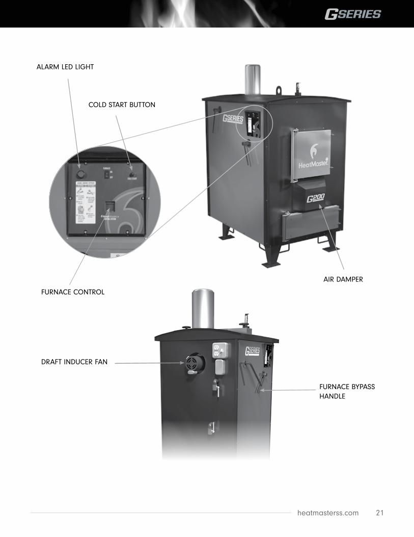
CONTROLS AND SAFETY DEVICESThis wood heater has a manufacturer-set minimum low burn rate that must not be altered. It is against federal regulations to alter this setting or otherwise operate this wood heater in a manner inconsistent with operating instructions in this manual.
Furnace Control Your HeatMasterSS G Series furnace uses a factory-programmed control to maintain your water temperature by using an air damper control and draft inducer fan. The control is located around the corner to the left of the firebox door and requires no user programming or changes. The control displays the water temperature in your furnace, the damper air percentage and any alarm messages, if set off.
NOTE: A timer has been programmed in to the control to fire the furnace after 1.5 hours of idling for 3 minutes and every 30 minutes after that. This timer will help to keep your coal bed lit during long idle periods. The timer settings can be adjusted. Contact your dealer for more information.
Air Damper The damper air percentage is the amount of air being drawn through the furnace to stoke the fire. This feature keeps your furnace burn clean and hot while keeping your water temperature in the preferred range. The damper is located beneath the firebox loading door and is a mechanical part that opens or closes the air injection port.
Draft Inducer The draft inducer fan is located at the rear of the furnace on the top and is used to draw air from the air damper through the furnace. The fan should be on whenever the air damper percentage is above 0% or when the furnace bypass is open.
Furnace Bypass Handle Use the furnace bypass when ever the firebox loading door is open. The bypass handle is located on the side of the furnace and opens a direct exit out of the fire-box through the chimney when ever pushed in toward the furnace. This will allow you to check your firebox, fuel and load your furnace without smoke spillage out of the firebox loading door.
CAUTION: Do not open any door before opening the furnace bypass. Damage to the furnace and personal injury may result.
High Limit SwitchThe high limit cut off switch is used to ensure the furnace does not cause damage via runaway fire. It acts as a safety switch by cutting power off to the fan if the water temperature rises above 190° F.
Alarm LED LightThe LED alarm light is located above the furnace bypass handle and will blink red if the furnace smoke by pass is open, the furnace is low on water or if the water temperature is too low or too high. It is intended to warn the user of potential problems.
Cold Start ButtonThe button is located on the control panel in the top right corner. Press the button to bypass the low temperature function of the control to fire the furnace from a cold start (First firing the furnace or when the water temperature has gone low).
heatmasterss.com 21
DRAFT INDUCER FAN
FURNACE BYPASS HANDLE
ALARM LED LIGHT
COLD START BUTTON
FURNACE CONTROL
AIR DAMPER

22
HOW THE G-SERIES GASIFICATION OUTDOOR FURNACE WORKSSteel Tech Inc is proud of it’s reputation of producing innovative outdoor heating methods and our G Series outdoor furnaces are continuing that trend. They operate more efficiently with fewer emissions than other outdoor furnaces. The HeatMasterSS G Series wood furnaces use up to 50% less wood to create the same heat.
How It WorksWood gas is generated in a high temperature reaction (>700° F) between the wood and a limited amount of oxygen. The heat and lack of oxygen “bakes” the wood, causing the gases in the wood to release in the form of carbon monoxide, hydrogen and carbon dioxide.
The wood gas mixture that is created in the firebox then gets forced through the base of the fire along with any ash that would come with it and burned at temperatures around 2000° F in the gasification chamber. This creates a very hot, very clean burn helping you get the most out of your fuel. After the gas is burned, heat is extracted to the water jacket using the heat exchange tubes.
Normal exit temperatures of the exhaust are 200-300° F.
The most notable indicator of effective gasification is the lack of smoke exiting the chimney. However, many times you will see white exhaust that dissipates quickly, which is steam from the wood in the firebox.
The gasification process creates longer burn times and can reduce wood consumption as much as 50% compared to a standard outdoor furnace.

heatmasterss.com 23
CARE AND MAINTENANCETo obtain the high levels of performance of your furnace, certain maintenance procedures are required periodically .
On a daily basis:• Ensure that all doors are closed and sealing
properly. Adjust if necessary.
• Check for creosote buildup in firebox and lower combustion chamber. Some creosote buildup along the walls, door jamb and firebox door is normal.
• Check water level.
• Clean heat exchange tubes by aggressively pushing and pulling lever back and forth at least 5 times.
• Check to make sure fan and control are functioning properly. The fan should turn on when the furnace calls for heat. The control display should be functional and keeping the water temperature between 160 and 180° F.
• Check for embers or ashes laying on the ground around the furnace and dispose of them.
• Make sure all covers and guards are in place securely.
• If the furnace is installed outdoors or in an uninsulated structure, make sure rear cover is securely on.
• Make sure the smoke bypass is closed (the handle should be facing the back of the furnace).
On a weekly basis:• Check for creosote build up in the heat transfer
tubes and chimney using the access panel on the rear the furnace.
WARNING: Always keep the firebox door open when removing ash from the Lower Combustion Chamber.
• Remove ash from Lower Combustion Chamber in the horseshoe refractory brick and both sides, carefully using your ash rake.
• Dispose of ashes in a metal container away from the stove and wood pile.
On a monthly basis:• Inspect air inlet for creosote build up or blockage.
• Depending on the type and quality of wood
being used, ash removal from the fire box may be necessary. For optimal performance the ash bed in the firebox should not exceed 6-8”. If you are burning a wood fuel that leaves quite a bit of ash you may need to clean your firebox out every 2-4 weeks to continue to get optimal performance from your furnace.
• Check fan motor and wheel for creosote buildup. The motor and wheel can be easily removed by unplugging the wires to the fan and removing the nuts on the stainless steel plate.
On a seasonal basis when furnace is not in use, you will have to:• Remove all ashes and excess creosote from
firebox, lower combustion chamber, heat exchange tubes and chimney.
• Check all gasket seals to make sure they are sealing. To replace, remove the old seal and residues from the door, scuff the surface where the seal is placed with sandpaper and re-apply high temp silicone. Lay fiberglass rope over silicone and let bond for at least 24 hours before using the furnace again.
• Cover chimney and crack open the bottom door enough to allow air movement and reduction of condensation within the firebox.
• Make sure your water tank is full and have your water treatment tested and adjusted to manufacturer’s specifications. See page 5 for exact specifications.
• Change your water filter cartridge and inspect all of your system for leaks.
• Tighten your firebox door by adjusting the hinges on each side of the door.
All covers and guards must be in place at all times, except for maintenance or service.
Care for the exterior of your furnace is minimal. The user must wash and remove ash and creosote regularly.
Ashes should be placed in a metal container with a tight fitting lid. The closed container should be placed on a non-combustible floor or on the ground well away from all combustible materials before final disposal. If the ashes are disposed of by burial in soil or otherwise locally dispersed, they should be
24
TROUBLESHOOTING
TROUBLESHOOTING TO ENSURE PROPER BURNING AND AIR FLOWIf your furnace is not producing enough heat, is smoking while burning, there is no exhaust coming from the chimney or there is general concern on how well it is functioning you can confirm functionality using this process:
1. Remove damper cover located below the firebox door and ensure the damper is opening the metal disc when the furnace is calling for heat and closing when the furnace is satisfied.
2. Use a light piece of paper like receipt paper and hold it up to the opening in the metal disc. The paper should suction to the opening. If it is not, there is an airflow issue in the furnace that should be diagnosed by your dealer.
3. Make sure ash bed is not so high as to block air holes in the panels on the sides of the firebox
4. Check to ensure the slot at the bottom of the firebox is completely open
5. Check to ensure all ash from the lower combustion chamber is removed and there are no block-ages. Make sure ash from the middle, both sides and behind the brick are cleaned.
6. Inspect top chamber of furnace and heat exchange tubes from blockage.
– Is there wet creosote build up?
– Do the spirals in the heat exchange tubes have
full movement up and down?
– Is there creosote build up in the fan housing or in the fan wheel?
Clean any creosote found by scraping it off.
7. Check chimney for blockage, inspecting all the way down into the furnace. Clean out any blockage.
More than likely, if there is a problem with the furnace burn or air flow, you will find it by checking these things.
If the actuator damper plates do not open or close as they should and the power in the furnace is acting appropriately:
1. Remove the bracket, spring and motor to get at the damper plates.
2. Remove plates and clean of any creosote, ice, dirt, etc.
3. Re-install and test for function.
If the furnace is running but fails to bring water up to temperature:
1. Check fire.
2. Check for power at furnace. Make sure control is running with no errors or alerts
3. Check fan for operation.
4. Check that the damper is open to allow air injection.
5. Check if the furnace is properly gasifying by opening the bottom door to the Lower Combustion chamber. A flame should be visible only for a short time after opening the door and glowing embers should be present. Keep arms, legs and head at least 3 feet from the opening.
retained in the closed container until all cinders have thoroughly cooled.
Creosote – Formation and Need for Removal. When wood is burned slowly, it produces tar and other organic vapors, which combine with expelled moisture to form creosote. The creosote vapors condense in the relatively cool chimney flue of a slow-burning fire. As a result, creosote residue accumulates on the flue lining. When ignited, this creosote makes an extremely hot fire. The chimney and chimney connector
should be inspected at least twice monthly during the heating season to determine if a creosote buildup has occurred. If creosote has accumulated it should be removed to reduce the risk of a chimney fire.
CAUTION: Make certain that all electrical power to the furnace and components is shut off. It can be washed using water and a mild non abrasive cleaner suitable for painted surfaces.
ATTENTION: Avoid direct water pressure to electrical components and connections.

heatmasterss.com 25
6. Ensure that the air slot in the firebox refractory is clear to allow proper burning
7. Check fuel type. Poor quality fuel will not provide as many BTU’s as high quality fuel.
8. Check water level of furnace.
9. Check for creosote blockage in the chimney and heat exchange tubes.
10. Check to ensure all pumps in the system are running.
11. Check to make sure there are no leaks, hot/wet spots on your ground or breaks in the pipe or fit tings which may cause the pipe to be saturated and lose its insulation value.
12. Check temperature of water exiting furnace, entering the building being heated and be fore and after each heat exchanger. Large temperature drops signal large consumption of the BTU’s produced by the furnace. If there is a large difference in the water at the top of the tank and the water coming from the supply outlet there is not enough flow in the water tank. (See next topic).
13. If everything is functional call your dealer.
If the water temp on the control is hot (170-180° F or higher) but the water temp in the supply line is cool
1. Ensure all lines on the furnace are being used to ensure enough flow and mixing in the furnace tank. If a line is not being used, install a re-circulation loop with a properly sized pump for your furnace’s required flow rate.
2. Check system for flow. High efficiency boilers require a certain flow rate to dissipate heat into the water jacket properly.
– Check to ensure all pumps in the system are running and none are turned the wrong way.
– Check filter cartridge for flow blockage (if installed).
– Check for air in the system at the exchanger by bleeding off.
– Check for closed valves to ensure water flow.
3. If no obvious flow issues arise from above system checks, turn off pumps on each line, close ball valves on the return lines. Remove return line and turn pump on again. Dump water in a 5 gallon bucket and time how fast it fills up. You should be
able to calculate flow rate in that line. Do this for each line coming off of the furnace to calculate furnace flow rate. Below are required flow rates for each G Series furnace:
G100 - 7 GPM
G200 - 16 GPM
G400 - 25 GPM
If the flow rate does not match what the furnace requires, make sure all lines on the furnace are being used. A recirculation line or additional pumps may be required to boost the flow rate. Have your dealer or a plumber inspect system for possible flow issues or air lock.
If the furnace water and the building supply lines are hot but buildings do not have heat:
1. Check to ensure all pumps in the system are running.
2. Check filter cartridge for flow blockage (if installed).
3. Check for air in the system at the exchanger by bleeding off.
4. Check for closed valves to ensure water flow. Check Temperature of water exiting the furnace, entering the building being heated and before and after each heat exchanger. Large temperature drops signal large consumption of the BTU’s produced by the furnace.
If the furnace overheats:
1. Close all air inlets and doors on the furnace
2. Retrieve as much heat as possible from the system by turning thermostats up and opening windows until furnace cools down.
3. Check that all doors are closing properly and that door gasket is completely sealing.
4. Check that the damper plate is opening and closing properly. It should be completely closed when the furnace temperature is over 180° F.
5. Check water level.
6. Check to ensure all pumps in the system are running.
If there is a runaway or chimney fire:
1. Make sure the firebox and ash pan doors are tightly closed.

26
2. Close all combustion air inlets on the furnace.
If the furnace has shut down:
1. Check to ensure that the unit has power.
2. Check to ensure the furnace On/Off switch is in the On position.
3. Check the water temperature (furnace has a high temperature cut off of 190° F and turns on again at 140° F).
4. Check control for errors that may have shut the furnace down.
5. If all checks have not corrected the problem have a technician check the control panel.
If there is a power failure:
1. Open all flow-check and zone valves in the system. Depending on the system design, this may allow convective circulation.
NOTE: This does not apply to gravity systems, as they have no flow-check valves and will continue to operate normally without electricity.
2. It is important to remember that the heating systems cannot dispose of a great deal of heat without the circulator(s) running. Avoid over-firing! DO NOT LOAD LARGE AMOUNTS OF SOLID FUEL INTO THE FURNACE! Fire the furnace cautiously until you are able to determine how quickly the heat system is able to absorb the heat being produced by the furnace.
3. When the power has returned, reset all flow-check and zone valves and resume normal operation of the system.
If there is smoke leaking out of the door
1. Check to ensure door is sealing properly.
2. If the seal is worn out it will have to be replaced.
3. The door may need to be adjusted. To do this loosen the door latch bearings and nuts on door hinge and set the door so it seals tightly against the door jamb. Re-tighten once door is in place.
If the furnace has an excessive amount of creosote
1. Check to ensure the furnace is sized accurately according to heat demand. If the furnace is oversized it will idle and cause this.
2. Check moisture content in your wood fuel. Moisture content over 30% may cause creosote buildup. Recommended moisture content in your wood fuel is 15-20%.
3. Using the top access door on the roof of the furnace, inspect the bypass door for smoke leakage
4. If the chimney and/or heat exchange tubes become plugged with creosote it will be necessary to scrape the creosote out to obtain a proper burn in the firebox.
You are having to fill the furnace with water more then once a week or more then a few gallons of water per week and there is no obvious explanation.
1. Check the temperature settings and gasket on the door and ash drawer to ensure the furnace is not over temperature and steaming. If water temperature reaches levels over 200 degrees Fahrenheit the water will steam and water loss will occur.
2. Check the perimeter of the furnace for water puddles collecting or dripping from the furnace.
3. Check all plumbing in the system to ensure there are no leaks.
4. If these checks have not provided an answer call your dealer.

heatmasterss.com 27
ELECTRICAL TROUBLESHOOTINGElectrical troubleshooting should always be done by a qualified technician
High Limit Switch:Using an electrical testing meter check for power on both poles of the high limit switch.
• If the furnace temperature is above 195° F. the switch should be OPEN and there should only be power on one pole of the switch. If the furnace was over 195° F. and the switch has opened the water will need to cool down to approximately 140° F. before it will close and allow power through once again.
• If the furnace has not over heated (190° F+) but there is still power on only one pole of the switch, the switch is faulty and should be replaced.
• If there is not power on either pole check for power at the main power switch at the rear of the furnace.
Control power supply switch:Using an electrical testing meter check for power on both poles of the power supply rocker switch. The switch has power in, neutral, and power out poles. During normal operation there should be power at the power in and power out poles.
• If there is only power on one of the poles check to make sure the switch is in the “on” position.
• If the switch is “on” and there is only power on one pole the switch is faulty and should be replaced.
• If there is not power on either the power in or the power out pole check for power at the high limit switch.
Siemens 24V DC Power Supply:Using an electrical testing meter check for DC voltage at the OUTPUT terminals.
• If there is 24 volts DC across the terminals and the green LED on the front is lit the power supply is working.
• If there is not 24 volts DC check for power on the INPUT terminals (this should be 115V AC)
• If there is 115V AC on the INPUT terminals but not 24V DC on the OUTPUT terminals the power
supply is faulty and should be replaced. Check for possible short circuits in the 24V DC wiring that may have caused the power supply to fail.
• If there is not 115V AC on INPUT terminals check for power at the Control Power Switch.
1 Amp fuse:Using an electrical testing meter check for 24V DC on the output lead from the fuse holder.
• If there is 24V DC on the output lead then the fuse is good.
• If there is not 24V DC on the output lead then remove the fuse from the fuse holder and check for continuity across the fuse. If there is not continuity the fuse has blown and should be replaced. Check for possible causes such as a short circuit in the wiring.
• If there is continuity across the fuse check for 24V DC power in the input lead to the fuse holder. If there is power there then check the fuse holder to be sure the fuse is seating properly.
• If there is not 24V DC power on the input lead to the fuse holder, check for power at the Control Power Supply.
Siemens LOGO Control: (with display)Using an electrical testing meter check for 24V DC power across the “L+” and “M-“ terminals.
• If there is 24V DC power at the terminals but the display remains blank the control is faulty and should be replaced.
• If there is not 24V DC power at the terminals, check the 1 AMP fuse that supplies power to the control.
Low Water Cut Off Switch:Check to be sure there is enough water in the tank of the furnace by removing the float assembly and looking in the fill pipe.
If the water level is low add enough to raise the water level so the float level shows full.
If the water level is full and the Low Water Alarm is flashing on the screen you will need to test the low water switch.

28
Using an electrical testing meter check for voltage across the “M-“ and “I1” terminals on the Siemens control. If the low water switch is satisfied (closed) there should be 24V DC.
• If there is not voltage, power off the furnace, isolate the low water switch from the control and the wiring, then check for continuity across the switch.
• If the switch has continuity, re-install the wires in their original positions and power up the furnace. The Low Water Alarm should disappear from the screen.
• If the switch does not have continuity, drain the furnace enough so that the water level is below the low water switch and inspect the switch. If it is dirty it may be cleaned up, tested and re-installed. If it is faulty it should be replaced.
By-Pass Door Switch:To test the By-Pass Switch, use an electrical testing meter and measure the voltage across the “M-“ and “I2” terminals on the Siemens control. There should be 24 VDC when the by-pass is in the CLOSED position.
• If there is not power across those terminals, isolate the switch wiring and perform a continuity test on the switch in the open and closed positions. The circuit should be “open” when the by-pass is OPEN and “closed” when the by-pass is CLOSED.
• If this is not the case the switch must be inspected. The roof must be removed from the furnace in order to inspect the switch. Check that the switch is wired to the correct terminals and that the striker is depressing the switch plate accurately. If this is all working well but there is no continuity across the switch when the By-Pass is CLOSED then the switch is faulty and should be replaced.
Cold Start Button:The cold start button will override the low temperature cut off feature of this furnace. It should be pressed once to allow the furnace to operate when in a cold start situation.
If the screen is flashing “Low Temperature Alarm” and the Cold Start Button is depressed, the alarm should
be replaced with “Cold Start Override”. This message will flash until the furnace has heated past 140° F.
• If the button is depressed and the “Low Temperature Alarm” continues the circuit should be tested using an electrical testing meter. Check for voltage between the “M-“ and “I3” terminals on the Siemens control when the button is DEPRESSED. There should be 24V DC across those terminals only when the button is depressed.
• If there is no power present, isolate the switch from the control and wiring and check for continuity across the switch. There should be continuity only when the button is depressed. If not, the button is faulty and should be replaced.
Damper Actuator:The “mode” selector should be set to mode 3.
To test for proper operation the furnace should be powered on and calling for heat. The display should indicate the desired Air Damper %. In this state you may test for power across terminals 1 & 2 on the actuator. There should be 24V DC across those terminals.
• To test for proper communication you may test the voltage across terminals 2 & 3. There should be between 3 and 10V DC depending on the Air Damper % displayed on the control. 3 volts corresponding to 30%, 4 volts to 40%, and so on.
• If there is no power across terminals 1 & 2 then check that there is power at the Siemens control. Test for power across terminal# 2 on output Q4 and terminal “M1” on the AM2 module.
• If there is power and communication to the damper actuator and it does not open or is stopped in the wrong position pry the outer damper plate away from the inner plate. If the plates have stuck or frozen to each other this should break them loose and the actuator should move freely. If the plates were stuck they should be removed and cleaned.
• If the plates are not stuck or frozen and there is power and communication the actuator is faulty and should be replaced.
heatmasterss.com 29
G100 and G200 Electrical Schematic
30
G400 Electrical Schematic

heatmasterss.com 31
Instructions for Editing Control SettingsTo edit temperature, differential, timer and low temperature cut off settings follow these instructions:
• To access the programming press the down arrow repeatedly until the programming screen appears.
Note: If the Low Temperature Alarm is on, DO NOT push the cold start button.
• Use the up and down arrow keys to toggle between settings screens.
• To edit the settings on the screen press and hold the “esc” key until the first value is highlighted.
• Use the up/down arrow keys to toggle to different settings on the screen.
• Press the OK button to adjust the highlighted setting.
• Use the left/right arrows keys to navigate to the appropriate character.
• Use the up/down arrow keys to adjust the value of the character.
Note: The values are always in minutes or degrees Fahrenheit.
• Press the “OK” key to save your changes and adjust other settings.
• Press the “esc” key to be able to toggle between screens.
• Press the “UP” arrow repeatedly to return to the run screen.
The following screens will be available to edit:
Temperature Settings
• The Set Temp Function controls how hot the water in the water jacket is heated to.
• The Differential controls how many degrees the water will lose before the furnace turns on to heat the water.
Timer Settings• The Timer settings are designed to help keep the
coal bed alive in the firebox during periods of idle.
• The On Delay controls how many minutes the furnace will idle before turning the fan on.
• On Time controls how many minutes the furnace will burn for when the Timer function is activated.
• Off Time controls how many minutes before the next Timer function is activated.
Note: This only activates after the furnace completes a burn cycle and brings the furnace up to temperature. If the furnace is required to turn on because the water temperature has fallen below the differential setting, the Timer Settings will reset to the On Delay timer.
Low Temperature Shut DownThere is a low temperature function programmed in to the control to shut the furnace down if the water temperature falls below the temperature set in the programming. This is done to preserve the heat in the water if the furnace has stopped burning.

HeatMasterSS carries a full line of high quality parts for your furnace including pumps, fittings and heat exchangers. For more information on our parts or to arrange product installation please contact your local HeatMasterSS dealer.
HeatMasterSS
Box 158 Winkler, Manitoba, Canada R6W 4A5 Phone: (204) 325-9792 Fax: (204) 325-9803Toll Free: 1-877-325-9792Email: [email protected]
heatmasterss.com