operation and maintenance manual chulliar dam
TRANSCRIPT

OPERATION AND MAINTENANCE MANUAL
CHULLIAR DAM MUTHALAMADA P.O.. PALAKKAD. KERALA — 678507.
Superintending Engineer
Siruvani Project Circle, Palakkad.
Executive Engineer
Irrigation Division, Chittur.
Assistant Executive Engineer
Irrigation Sub Division No. I, Chittur.
Assistant Engineer
Chulliar Dam Section, Muthalamada P.O.

CONTENTS
CHAPTER 1
GENERAL INFORMATION
1.1 Introduction
1.2 Purpose, location, description of dam
1.3 Salient Features of Chulliyar Dam
1.4 Responsible officials
1.5 Roles and Responsibilities of the AE and AEE
1.6 Roles and Responsibilities of the EE and SE
1.7 Collection & Reporting of Dam and Reservoir Data
1.8 Records kept in the office of the Assistant Engineer.
1.9 Public and Project Staff - Health and Safety
CHAPTER 2
PROJECT OPERATION
2.1 Basic Data
2.2 Flood Management
2.3 Regulation of water for Irrigation
2.4 Regulations of spillway shutters
2.5 Maintenance
2.6 Access Roads
2.7 Record Keeping
CHAPTER 3
PROJECT INSPECTION
3.1 Types of Inspections
3.2 Pre- and Post-Monsoon Checklist and Example of Report Proformas

CHAPTER 4
PROJECT MAINTENANCE
4.1 Maintenance Priorities
4.2 Surface Preparation and Painting of HM Works
4.2 Electrical System
4.3 Maintenance of Metal Gate Components
4.4 Access Roads
4.5 General Cleaning
4.6 Materials and Establishment Requirements during Monsoon Period
4.7 General List of Maintenance Records
4.8 Preparation of O&M budget
4.9 Maintenance Records
CHAPTER 5
UPDATING THE MANUAL
APPENDIX 1 – BASIC DRAWINGS OF CHULLIYAR DAM
GLOSSARY

CHAPTER 1 GENERAL INFORMATION
1.1 Introduction
This document represents a detailed Operation and Maintenance (O&M) Manual for Chulliyar
Dam, Kerala, providing written descriptions of procedures for ensuring that the dam operations
safely and is kept in good condition by periodic inspections, repairs, maintenance in a
sustainable manner. Timely maintenance is important for the continued safe functioning and
productive use of the dam and reservoir.
The Manual has been prepared primarily for the dam operation’s staff and their supervisors
who are assigned the responsibility for the physical operations and maintenance of the dam. It
contains, as a minimum, all information and instructions necessary for them to perform their
allotted tasks in a safe manner. In addition to instructions for dam operations staff, the Manual
includes all necessary instructions for other staff directly or indirectly involved in operating
and maintaining the dam.
It is essential that the Manual or a copy of the Manual along with supporting data including the
atlas of all drawings and manufacturer’s technical documents is available at site for ready
reference.
1.2 Purpose, location, description of dam
Chulliar dam is built across Chulliyar River, a tributary of Bharathapuzha in Palakkad District,
Kerala State and meets water requirement of an ayacut of 2430 Ha. Chulliar Project is the stage
II of Gayathri Irrigation project. A graphical representation of Bharathapuzha river basin is
shown in Fig 1. This project was taken up in 1961, partially commissioned in 1966 and
completed in the year 1970. Gross storage capacity of the reservoir estimated at FRL of
+154.08 m is 13.73 Mm3.
Water distribution for agricultural purpose generally begins in the month of November every
year and continues till February or March. Major crop cultivated in the ayacut is paddy. The
reservoir is located in Muthalamada Panchayath of Chittur Taluk and the Legislative Assembly
Constituency is Nemmara.
The Dam is located at latitude of 100 36' N and longitude of 760 46' E. Chulliar dam is
a composite dam having masonry dam of length 555m lying in East-West direction, and flanked
by earthen dam at its west end in perpendicular direction which extends southwards for 700 m.
1

Also, there is a saddle dam of length 500 m at the south side of earthen dam. An aerial view of
Chulliyar Dam is shown in Fig. 1.2.
1.3 Salient Features of Chulliyar Dam
Dam Chulliyar
Project Gayathri Irrigation Project Stage II
Tributary/River Chulliyar/Gayathripuzha/Bharathapuzha
Type of structure Masonry dam
Location Latitude 10 °36’
Longitude 76 ° 46’
Place situated Muthalamada
Village/Taluk/District Muthalamada/ Chittur /Palakkad
Year of completion 1966
Classification Medium Irrigation Project
Length Masonry - 555m Earthen -1200m
Width at top 3.6m
Maximum height from foundation 30.5m
Gross storage 13.7 Mm3
Live storage 12.7Mm3
Dead storage 1 Mm3
Dam top level +155.94 m
Maximum Water Level +154.08 m
Full Reservoir Level +154.08 m
Minimum Draw Down Level +136.55
Catchment area 27.8 sq.km
Water spread area at FRL 1.65 sq.km
Probable Maximum flood (Standard
Project Flood) 449 cumecs
Spillway details
Shape Ogee
Length 30m
2

Type, No & size of gates Vertical lift type 3 nos, 7.65mx3.05m
Capacity 223.7 cumecs
Crest level +151.03
Canal LBMC-13.5km
Utility Irrigation, aquaculture
Ayacut area 2430 ha
3

Fig. 1.1 Bharathapuzha river basin
4

Fig. 1.2 Aerial view of Chulliyar Dam
5

1.4 Responsible officials The Irrigation Department, Government of Kerala is the owner and has the final authority
and responsibility for the operation and maintenance of the dam. Identification of all areas of
responsibilities connected with the operation and maintenance of the dam are covered in this
section. The officer’s responsibilities for the various functions are identified by their designation
and, in particular, the responsibilities of operating personnel are specifically identified in below
and includes regularly scheduled duties which staff personnel are required to perform as outlined
in the following tables: Table 1.1 – Overall Responsibilities for Chulliyar Dam
Sl No Particulars Remarks
1. Implementing Agency Irrigation Department, Government of Kerala
2. Project Administration Officer in charge Chief Engineer, Project 1, Kozhikode
3. Operations of Equipment at the Dam Executive Engineer, Irrigation Division, Chittur
4. Reservoir inflow and Flood forecasting Executive Engineer, Irrigation Division, Chittur
5. Authorizing spillway flood releases Executive Engineer, Irrigation Division, Chittur
6.
Authorizing releases for various purposes like irrigation, water supply hydro- power, etc.
Executive Engineer, Irrigation Division, Chittur
7. Recording reservoir Data Executive Engineer, Irrigation Division, Chittur 8. Routine inspection Executive Engineer, Irrigation Division, Chittur 9. Maintenance Executive Engineer, Irrigation Division, Chittur. 10. Instrumentation Executive Engineer, Irrigation Division, Chittur
1.5 Roles and Responsibilities of the AE and AEE Table 1.2 – Roles & Responsibilities of AE and AEE
General responsibilities of AE and AEE
1. Operation of Canal sluices as per the direction of higher officers.
2. Operation of Spillway shutters as per the direction of higher officers.
3. Daily reporting of Reservoir data as per the direction of higher officers.
4. Inspecting the gallery and shutter operation on daily basis and reporting any irregularities to higher officers.
During flood conditions
6

1.
Maintain the reservoir water level gauge register and to report the reservoir data in every 6 hrs. when the reservoir reaches 200.00 m, reporting of reservoir data in every 2 hrs. when it reaches 200.02 m and reporting of data in every one hour when it reaches 202.30 m and to bring to the notice of EE/SE/CE.
2.
Giving timely warning, to District administration, District Police Chief, Tahsildar Chittur and Palakkad, District Administration, Coimbatore, Local Self Government Institutions, Media, and all higher officials of the Department, such as first warning when the reservoir reaches 202.00 m “Chulliyar reservoir level at 202.00 m, only 1 m below full reservoir level”. Giving second and final warning when the water level reaches 202.30 m
“Chulliyar reservoir level at 202.30 m, shutters being opened”.
3. When the reservoir level attains 200.00 m AE should closely watch the inflow rate and levels. He should watch closely the downstream face of the earthen dam, seepages through toe drains and drainage gallery.
4. Assist the EE/SE/CE to issue notification to the villagers downstream in Newspapers, Radio, TV News channel to be alert regarding the flood situation
5. Assist the EE/SE/CE to coordinate with the Revenue authorities (District Administration) to alert the downstream villagers to evacuate the flood zone to prevent loss of life and live stock
6.
Assess the inflows in the reservoir as per the approved reservoir operation and to prepare proforma consisting of the status of the reservoir capacity and releases from the reservoir as per the standard Performa and to submit to the EE/SE/CE
7. Submit to the EE/SE/CE on the inflows and releases from the reservoir and status of the reservoir twice in the day.
8. Maintain the spillway crest gate operation log book
9. Operate the Spillway crest gates for flood mitigation as per the instructions of the EE/SE/CE and to update the Gate operation Log book
10. Maintain the pump operation log books for the dewatering pumps in the drainage gallery and to submit to EE/SE/CE
11. Observe the gates and to see that the drain holes are not clogged and floating debris is not deposited in the gate components
12.
Monitor the condition of the Welding transformers, gas cutting sets, umbrellas, tool kits torches chain blocks ropes ballies etc. on daily basis and to see that things are in place to handle any emergency situation
13. Observe the Gates, hoists and handling equipment during operation for the smooth movements and to immediately report any untoward excessive sounds in the motors, pumps or vibrations in the gate
14. Observe the dam top, embankment, catwalk, approach roads are well maintained by housekeeping personnel
15.
Observe the performance of the Dam and its appurtenant structures / Gates and Hoists during flood water releases and to report to the EE/SE/CE in case of any untoward incidents or malfunctioning of the gates of excessive seepages, leakages etc.
16. Assist EE/SE/CE to share the flow data and the reservoir storage details to the Media on day to day basis
1.6 Roles and Responsibilities of the EE and SE Table 1.3 – Roles & Responsibilities of EE and SE
Step Flood condition assessment, warning, flood mitigation, and other responsibilities
1. To issue notification to the villagers downstream in Newspapers, Radio, TV News channel to be alert regarding the flood situation
7

2. Assist the CE to coordinate with the Revenue authorities (District Administration) to alert the downstream villagers to evacuate the flood zone to prevent loss of life and live stock
3. Assist the CE to coordinate with the CWC flood monitoring authorities on the flood condition
4. Submit to the CE on the inflows and releases from the reservoir and status of the reservoir twice in the day
5. Operate the Spillway crest gates for flood mitigation as per the instructions of the CE and to update the Gate operation Log book
6.
Observe the seepages in the drainage Gallery with respect to the reservoir head and record the seepages in the infiltration gallery and to immediately bring to the notice of the CE in case of excessive seepage, leakage in any specific blocks and porous drains
7. Observe the Gates, hoists and handling equipment during operation for the smooth movements and to immediately report any untoward excessive sounds in the motors, pumps or vibrations in the gate
8. Observe the dam top, embankment, catwalk, approach roads are well maintained by housekeeping personnel
9.
Observe the performance of the Dam and its appurtenant structures / Gates and Hoists during flood water releases and to report to the CE in case of any untoward incidents or malfunctioning of the gates of excessive seepages, leakages etc.
10. Assist CE to share the flow data and the reservoir storage details to the Media on day to day basis
1.7 Collection & Reporting of Dam and Reservoir Data A proforma is provided to ensure that dates and times for the collection and reporting of vital information is recorded and documented for the record.
• Reservoir water surface elevation.• Reservoir inflow.• Spillway outflow.• River releases.• Irrigation.• Weather related data.• Instrumentation data.• Water quality.Instructions and a standard proforma for collection and reporting of inflow and outflow
data, and other pertinent data, is shown in Figure 5 below.
Records of the following operations at Chulliyar Dam are to be maintained in a chronological manner for reference. These records are helpful for identifying preventative maintenance measures that may need to be taken up, troubleshooting the cause of potential equipment failure and documenting development of any unusual conditions.
• Date and Time• Attendance statement during normal operations – both during monsoon and non-
monsoon periods.• Operations of the spillway gates and outlet works.• Operating hours of mechanical equipment.• Testing / Operation of spillway gates and associated controls.• Testing/operation of Outlet gates, valves and associated controls,• Maintenance activities carried out.• Reservoir and dam inspections.
8

• Unusual conditions or occurrences, including acts of vandalism.• Attendance statement at the dam during emergency operations.• Changes to normal operating procedures.• Communication network checks.• Safety and special instructions.• Names of officers and staff carrying out inspections and maintenance.• Any other item pertaining to the operation and maintenance of the dam.
9

Table 1.4 – Example Proforma for recording Flow Data
For the Month of
Date Time Water level
in Mtr. Inflow in Cumecs
Out Flow in Cumecs
Reservoir Capacity in Mm3 Spillway Gates Sluice Release Total O/F
10

1.8 Records kept in the office of the Assistant Engineer.
1. Attendance statement
2. Operation of spillway gates and outlet works.
3. Operation hours of mechanical equipment.
4. Testing/operation of spillway gates, stop logs and associated controls.
5. Testing / operation of outlet gates valves and associated controls.
6. Maintenance register
7. Inspection of dam and reservoir
8. Unusual conditions of occurrences including vandalism
9. Attendance statement at the dam during emergency operation
10. Changes to normal operating procedures.
11. Communication network checks
12. Safety and special instructions
1.9 Public and Project Staff - Health and Safety As safety of Staff is of prime concern, safety instructions & protection measures at the dam are carried out by all staff.
1.9.1 Restricted Areas Certain areas of the dam and reservoir are restricted for entry of the general public. The purpose of restrictions is for security and safety of the dam, public safety and uninterrupted safe operation of the dam.
Restricted areas will include the following:
• Confined spaces such as galleries, sluice control rooms, shutter operating area, power roomand Dam safety Control rooms.
• Spillway approach areas, chutes and stilling basins.• Control buildings and valve areas.• Intake or outlet channels adjacent to hydraulic structures.
1.9.2 Details of the Security arrangements at Chulliyar Dam Site. The security arrangements of Chulliyar Dam are entrusted to
Watchmen (Departmental staffs) are engaged during day time
11

For Night hours, SEWAK, an outside agency under the chairmanship of districtcollector has been entrusted for the security of the dam.
Figure 1.3 - Organization Chart
1.9.3 Schedule of General Duties for Project Engineers Schedules of duties being performed by the staff assigned to various locations and components of Chulliyar Dam are provided in this section. All activities are to be recorded daily in the Log- book and site registers.
DAILY
• Visual inspection of dam
Crest of dam (Dam top)
Upstream and downstream faces
Visible portions of foundation and abutments contacts
Galleries
• Record water surface elevation. (during monsoon on hourly basis)
• Record reservoir inflow and spillway discharge. (during monsoon on hourly basis)
• Record releases from outlets /sluices.
• Record seepage from drainage systems-Toe drains, Gallery drains etc. on dailybasis (during initial filling of the reservoir)
CHIEF ENGINEER PROJECT 1, Kozhikode
SUPERENTENDING ENGINEER, SIRIVANI PROJECT CIRCLE, Palakkad
EXCECUTIVE ENGINEER, IRRIGATION DIVISION, Chittur
ASSISTANT EXECUTIVE ENGINEER, IRRIGATION SUB
DIVISION No. 1, Chittur
ASSISTANT ENGINEER, CHULLIYAR DAM SECTION,
Muthalamada.
12

• Record meteorological data.
• Check security and safety devices.
• Complete logbook / site registers which should include the above information
WEEKLY
Electrical System
• Standby generator (DG Sets)
Run for 15-30 min to achieve recommended operating temperature
Check status of batteries and keep them charged.
Check Fuel Supply
Drainage systems - Toe drains, Gallery drains etc., and, during any reservoir fillingoperations
Lighting arrangements in dam premises.
MONTHLY
Check condition of:
Dam and Reservoir
• Reservoir periphery (During Monsoon)
• Drainage systems - Toe Drains, Gallery drains etc. (on regular basis from second
year onwards after initial reservoir filling)
• Measuring devices/Instruments
• Security and safety devices – rectification, if needed.
• Communication Devices
• Status of Vegetation growth
• Check Sign/Warning display boards near vulnerable locations are in place and updatedas necessary
Mechanical/Electrical System
• Replace fuses/light bulbs, as necessary
• Inspect and maintain ventilation system; check for and remove any obstructions
• Cleaning of control panel boards
QUARTERLY
Outlet Works
• Availability of updated operating instruction
• Check gate air vents
• Clean gate control switchboxes
• Check operation of gates and valves
13

• Grease gate hanger / dogging arrangements
Check
• Check condition of Outlet works & the Energy Dissipation Arrangement (EDA)
Spillway
• Check for debris in inlet channel
• Check operation of gates
• Check for damages in spillway glacis, EDA, d/s area, etc.
• Check and clear spillway bridge drains
• Clean inside of motor control cabinet and remove debris, insect (bee nests), nests,rodents and bird nests
Other works
• Check for adherence to instrumentation schedule
• Record pertinent information in Operation Log
• Check conditions of V-notch weirs/other seepage measuring devices
BI-ANNUAL
Spillway & outlet works
• Check paint on gates and other areas of corrosion
• Check lubrication of wire ropes and application of cardium compound.
• Check mechanical hoist bearings and flexible coupling bearings
• Check gear systems
• Exercise gate and valves for operational efficiency
• Check oil reservoir level in hydraulic system and top up as necessary
• Check pressure release valve and clean any debris, dirt, other foreign objects as necessary
• Lubricate gate rollers
• Check rubber seals and seal clamp bar
Electrical System and Equipment
Change oil in stand by generator
Check exposed electrical wiring of:
Operating equipment of gates/valves/hoists of Outlet works.
Operating equipment of gates and hoists of Spillway
Operating equipment of any other gates and hoists in dam
14

Spillway catwalk / bridge
Dam Gallery
• Check Gate limit switches and adjust
ANNUAL
Spillway &Outlet works
• Paint
Metalwork, Gate, Hoists and all exposed metal parts for corrosion
Valves / Control valves
• Hydraulic power pack system
• Exercise Gates and Valves
• Examine stilling basin / energy dissipation arrangement and d/s channel & carry outrec- tification works, as necessary.
• Check metal welds for damages/cracks in Gates, Hoist platform, Radial Gate Tieflats, Trunnion Girders/supports etc.
Electrical
• Check electrical conduits, pull-boxes and switches for:
Outlet works valve house
Gates & hoists
Spillway bridge
Gallery
FIVE YEAR (PERIODIC)
• Inspect stilling basin / energy dissipation arrangement, which normally are underwater;less frequent if experience indicates. This may need to be done by carrying outdewatering or by divers/remote operated vehicle (ROV) as necessary.
• Review Dam operation procedures and EAP and update as necessary.
1.8.2 Hydro-Mechanical Inspections / Checks
Special duties performed for H-M operating personnel works are given in this section. Frequency of inspections / checks for hydro-mechanical components and necessary actions to be taken up during maintenance
1. Vertical Spillway Shutters - 3 Nos.
a. Embedded Parts
Sl. No. Embedded Part Frequency
1
Checking of seal beams. Seal Seats, Guide track & all other exposed embedded parts with respect to their alignment, distortion: if any due to continuous use, pitting and un-necessary cracks due to wear & carrying out requisite repairs, rectification by welding, grinding etc.
Half Yearly
15

2 Removing debris & other foreign material deposited on embedded parts & cleaning the same Monthly
3 All cracks & defective weld joints to be ascertained & rectified. Half Yearly
4
All dirt, debris, grit, foreign material etc. to be removed from trunnion assemblies as well as trunnion chair and lubricate trunnion bearing & the sliding surface on trunnion chair with specified lubricant/ grade to ensure smooth sliding movement of trunnion.
Monthly
5 All nut bolts connecting Trunnion Assembly & Trunnion Chair and Trunnion & Yoke, girder Trunnion pin lock plate to be checked & Tightened and replacement the same if found defective.
Monthly
b. Gate Structure
Sl. No. Embedded Part Frequency
1 Regular inspection of the gate along with the hoist to be carried out daily to ensure that there is no unusual development/ observation Daily
2 Check all welding for soundness & rectify defects Quarterly
3 Check welding between arms & horizontal girders as well as arms & Trunnion with the help of magnifying glass for cracks/ defects and rectify the defects.
Quarterly
4 Clean all drain boles including those in end arms, horizontal girders & Trunnion Quarterly
5 Check all nuts & bolts provided and tighten them, and replace the de- fective nuts & bolts Quarterly
6 Check upstream face of Skin plate for pitting, scaling and corrosion. Scaling formation are to be removed. Pitting shall be filled with weld & ground. Corroded surface shall be cleaned & painted
Yearly
7 Joints of side & bottom rubber seals to be checked for their proper alignment and fixing & to be rectified/ adjusted if there is leakage through joints
Monthly
8 Nuts & bolts for rubber seal connection to be tightened and damaged nuts and bolts to be replaced Quarterly
9
The excessive or widespread leakages if any shall be reported to the en- gineer in charge. If the seals are required to be replaced the same shall- be carried out after supply of rubber seal by the department free of cost in case the change of rubber seals is more than once during total maintenance period of five years
Quarterly
10 The guide roller pin is to be lubricated Quarterly
2. Manually / Electrically operated Hoist: - 3 Sets
16

Sl. No. Description Frequency
1 Checking of oil level of power packs and pouring of make-up oil as & when required Daily
2 Checking, adjustment & repairing of relief & flow Monthly & during rainy sea- son
3 Checking, adjustment & repairing of pressure switch & flow switch, solenoid valves, etc.
Monthly & during rainy sea- son
4 Checking, cleaning, etc., of all filters, silica gel etc., & their replacement and when required Weekly
5 Checking & repairing & replacement whenever necessary, oil seals, 0- rings, ferules, argon welding, etc. of hydraulic pipe lines
Every
2 months
6 Checking of the main and pilot pressure of the system for their desired level & adjustments, required repairing Weekly
7 Checking, adjustment & repairing of all measuring system such as TGSE, etc. Monthly
8 Checking, repairing and replacement whenever necessary of all valves, valve seals, couplings of pipe lines, etc. Monthly
9 Checking, repairing & making good o f all electrical wirings & connec- tions of local panels Monthly
10 Checking, repairing & making good and replacement of all electrical contractors, timers, limit switches, fuses etc. including setting of limit switches
Monthly
11 Checking & maintaining hydraulic accumulator charging pressure Weekly
12 Complete trouble shooting of the entire system as and when necessary to maintain the same such that the system can be put to operation at any point of time as per requirement
Weekly
13 Checking and ensuring perfect lubrication of the entire equipment with recommended lubricants & methods of the manufacturer. Monthly
14 Checking & ensuring adequate hydraulic oil of standard make by mak- ing up short falls if any Monthly
15
The maintenance of the equipment cleaning & shall include inspec- tion, checking and ascertaining the deficiencies in the equipment for its smooth & trouble- f r ee operation. The deficiencies noticed shall be rectified by resorting to cleaning, adjustment, repairs, replacement of troubled/ damaged parts as per the requirement
As per
requirement
16 Necessary maintenance records are to be prepared as a result of period- ical inspection and submitted for deciding actions in respect of neces- sary repair/replacement of parts
Monthly
3. Stop Logs Embedded parts
17

Sl. No. Description Frequency
1
Inspection, checking of sill beams, side seals, guide track and other exposed embedded parts with respect to their alignment cracks, dis- tortion, pitting, uneven surface due to wear & tear. and ascertaining defects. Carrying out requisite repair/rectification by welding, grind- ing etc. as per requirement
Half Yearly
2 Removal of debris and other foreign material deposited on the E.P. and cleaning the same Quarterly
3 All cracks & defective weld joints of E. P. to be ascertained & recti- fied by respective welding Quarterly
1.10 Distribution of Operation & Maintenance Manuals The list of unit officers to whom the O&M Manual is required to be distributed is shown in the table below.
Table 1.5 - Distribution of O&M Manual and Revisions
Sl No Unit Officers Number of Manual Distribution
1. Secretary to Govt, Water Resources Department 3
2. Chief Engineer, Irrigation & Administration, Thiruvananthapuram. 2
3. Chief Engineer, IDRB, Thiruvananthapuram. 2
4. Chief Engineer, Project - 1, K o z h i k o d e 2
5. Superintending Engineer, SPC, Palakkad 1
6. Executive Engineer, Irrigation Division, Chittur 1
7. Assistant Executive Engineer, Sub Division No. 1, Chittur 1
8. Assistant Engineer, Chulliyar Dam Section, Muthalamada 1
9. Library, IDRB, Thiruvananthapuram 1
18

CHAPTER 2 PROJECT OPERATION
2.1 Basic Data
The Chulliyar operation plan consists of step-by-step instructions for operating the
dam and reservoir during routine (normal) and emergency conditions. The operating
procedures for normal operations are discussed in this chapter including operating criteria
for the reservoir, spillway & outlets. The operation of a dam involves regulation of its
reservoir as per project specific requirements. This includes the use of area capacity curves
and design flood; both are described below.
2.1.1 Area Capacity Curves
The area capacity curves for Chulliyar Dam tabular and graphical form are shown
in Table 7 and Figure 3.
2.1.2 Design Flood and Features Related to Safety
The maximum flood design at Chulliyar Dam site was at 223.70 cumecs.
The spillway is designed for this design flood with a maximum discharge of 449 cumecs.
The design flood has been reviewed under DRIP.
2.2 Flood Management
19
2.2.1 Recommended Gate Operation Procedures for Normal Flow Conditions
Under normal flow conditions, the reservoir is operated according to the previously
proposed elevations.
Sequence of Opening or Closing of Gates.
The gates were opened in a systematic manner, such that the end gates are opened first and

finally the central gate. No gate· is opened more than 0.2m. If the release over the spillway
is to be further increased, the gates are opened further in a similar manner, no gate opening
being more than 0.4m. Further opening of gates, if required is done in the same way,
keeping the difference in the openings if any two adjacent gates not more than 0.2m.
During the recession part of the inflow hydrograph, it may be necessary to close the crest
gates in order to maintain the reservoir level at the Proposed elevation. In such a case, the
closure of the gates should be done in the reverse order; the gate opened last being closed
first, the entire operation being such that the difference between the adjacent gate
openings never exceed 0.2-m.
2.2.3 Inflow Forecasting
The gross storage of Chulliyar Dam at FRL 154.08 m is 13.7 Mm3. The Chulliyar Dams
have been designed for a probable maximum flood (PMF) of 449 cumecs.
During monsoon, incident rains in the catchment area cause the flash floods in Chulliyar
river. The- se floods may lead to problems like people getting displaced from their homes,
huge damage to crops and other assets. The floods can have disastrous impact on the
environment also. Adequate measures are required to be taken up in advance to control
and regulate the flow water in the river.
The following measures are essential for effective management of floods during the
monsoons.
• Nomination of liaising officers at key points.
• Sharing of powers to concerned officers responsible for flood management.
• Exchange of data regarding rainfall, releases from dams, reservoir water levels.
• Reservoir operation schedules.
• Exchange of data regarding rainfall, releases from dams, reservoir water levels.
We have established offices at downstream of Chulliyar for assisting in flood warning
in the Chitturpuzha Basin. Based on the rainfall in the catchment and flow in the river and
tributaries, those office will furnish flood forecasting reports to other concerned offices,
whenever there is a probability of flood. It also informs the trend of flow (Raising, steady
or Falling)
The list of rain gauges in the catchment of Chulliyar basin and daily rainfall is to be
collected by concerned offices. It will helpful for prediction of probable floods in the river.
21

During monsoon daily water releases from the Dams at 8 hrs. & 16 hrs. in normal
situation and hourly data exchange during heavy floods is necessary. In this regard, the data
is required to be established. The data regarding exchange floods is made available to the
Revenue authorities and public by broadcasting in AIR, TV and publication in new papers.
2.2.4 Flood communication system:
The widely time-tested Communication to reach every corner of the flood affected
zones have been radio and television and private media for the people to move to safer
places by themselves in an emergency.
Communication is very important in such occasions These days due to revolution
in the telecommunication system, there is available, network of mobile phones. Advantage
of this facility will be taken. Mobile numbers of all such staff will be listed and made
available to all the personnel who have been assigned duty of disaster management.
Following liaising officers for flood co-ordination of Chulliyar Dam are as listed below,
Assistant Engineer, Phone No. 08426281038 Mobile No. 9964696492
Executive Engineer, Phone No. 08426281063 Mobile No. 9964696492
2.3 Regulation of water for Irrigation:
A project Advisory Committee consisting of representatives of the Agriculture local
members of the Legislative Assembly and Officers of concerned departments shall be constituted
to advise the Executive Engineer regarding the opening an operation of the canal system and
connected matters. The first opening and final closing of canals shall be done only under the
orders of the Executive Engineer. The first date of opening before 1st June shall be considered
only if the storage two reservoirs together is above 6 Mm3 the probable date of shall be published
in advance by the Executive Engineer in with the Project Advisory Committee.
If the crop pattern is altered by any cultivator ate fitting with the crop pattern adopted by
the project authorities the Project Officers are not bound to supply water to these fields and shall
not be responsible for consequent damage.
The operation of the sluices and maintenance of the supply during the crop season shall
be controlled by the Assistant Engineer under whose directions and the Junior Engineer shall
operate the sluice and shall maintain the required supply. Opening and operating the sluices as
direction by the Junior Engineer or work Superintendent, watching the canals, routine
maintenance of the canals such as removal of obstructions to flow etc. are the duties of the Lascars
22

working under the directions of the Work Superintendents. Each Lascar shall maintain a diary in
proper form, giving all date regarding the distribution of water in his jurisdiction. This diary shall
be inspected by the Work Superintendent at least thrice in a week by the Junior Engineer at least
once in a week. The Work Superintendents shall ensure that the Lascars abide by the rules and
regulations and supervise the work of lascar. The work Superintendents shall be responsible to
furnish readings at head sluices and tail dam of every canal to the Junior Engineer at regular
intervals and also when there are sudden changes. He shall also bring to the notice of the Junior
Engineer any encroachment on Government land or any cutting, opening of canal bund and illegal
use of canal water etc. The jurisdiction of the Lascar, Work Superintendents, Junior Engineers
and Assistant Engineers are given in statement No.1. None of these officers shall leave his
jurisdiction during the irrigation season without entrusting the responsibility of the distribution
system with any other responsible officer and without prior sanction of his immediate superior.
Water requirements of crops shall be at from the rainfall received in the ayacut as far as
possible and irrigation water shall be supplied only to supplement the rainfall. The details of the
rainfall shall be collected by the Junior Engineers and the supply in the canal shall be regulated
suitably. Any alteration in the canal supply shall be immediately reported to the Assistant
Engineer.
During the summer month and during certain other period when the storages in the
reservoir may not be sufficient to allow full discharge in canals intermittent system of Irrigation
shall be adopted. For this purpose, the left bank canal shall be divided into two reaches, the 1st
reach from 6/200 to 13/600 Km. and the second reach from 13/600 to 20/500 km.
2.3.1 Special precautions: -
The two reservoirs at Meenkara and Chulliar have to be operated judiciously so that the
storage in one reservoir supplements the other. Scarcity in one reservoir may be made from the
other so that the two reservoirs together may be treated as a combined storage.
2.4 Regulations of spillway shutters:
The junior Engineer, Chulliar dam will be in charge of the operation of spillway gates of
Chulliar dam. All the waters reaching the reservoirs shall be impounded until the levels in the
reservoir levels in the reservoirs are about 0.6 m below F.R.L. Daily reading of the reservoir levels
shall be taken at 8.00 and all data regarding the reservoir shall be sent by concerned Junior
Engineer in Form I or Form II as the case may be to the Assistant Engineer, Executive Engineer,
Superintending Engineer and to the Chief Engineer. When the water level is raising and its reaches
23

2 m below F.R.L (i.e. When the level reaches + 152.08) in Chulliar reservoir water level shall be
noted every six hours. When the water level reaches 1 m below F.R.L the water level shall be
noted every hour.
When the water level is rising and reaches 1.25 m below F.R.L the Junior Engineer shall
immediately inform the Assistant Engineer about this. The Assistant Engineer shall as a first
warning, send the following telegraphic messages to the Officers listed below.
Message: - “Chulliar reservoir level 1.25 m below full reservoir level shutters likely to be
opened”.
Officers to whom the message to be sent:
• The District Collector, Palghat
• The Tahsildar, Chittur
• The Tahsildar, Alathur
• The Executive Engineer, Irrigation, Chitturpuzha.
The Assistant Engineer shall also shall closely watch the inflow rates in the reservoirs. Then the
water level in the reservoir reaches 0.6 m below F.R.L. (i.e.+ 153.48 m for Chulliar reservoir) the
Assistant Engineer shall send the following telegraphic message to the officers listed in Rule – 16.
Messages: - “Chulliar reservoir level 0.6 m below full reservoir level shutters are being
opened”.
Then the reservoir levels are rising and reaches 153.46 m in the case of Chulliar dam, the spillway
shutters shall be opened. The opening of all the shutters shall be kept equal. The water level in the
reservoir shall not be already to rise above the (+151.05 m in the Chulliar reservoir). With this
limit, the passing down of the flood water shall be limited as far as possible to the flood carrying
capacity of the river.
The Assistant Engineer shall closely watch the inflow rates and give instructions to the
Junior Engineer concerned regarding the opening of shutters etc. These instructions shall be
written in the gauging register kept at the Dam site.
The District Collector, Palghat is primarily responsible for taking necessary action to alert
the people likely to be affected by floods and for taking suitable steps for safeguarding the life and
property. The District Collector shall decide the measures to be followed in this regard in
consultation with the Executive Engineer, Chitturpuzha.
24

2.5 Maintenance:
The Assistant Engineer shall instruct in the first week of June every year all motors and
other equipment for operating sluice and spillway shutters are and ensure that they are in good
condition. He shall record his findings in the gauging register, on the date of instructions.
It is the primary responsibilities of the Lascars to maintain the canal system properly and
to reports to his superior officers any action by anybody violating the provisions of the irrigation
Act. The Lascar should inspect the entire length of canal in his jurisdiction at least 3 times in a
week or as often as may be fixed by the Junior Engineer. The Work Superintendent shall inspect
the canal in his jurisdiction twice in a week and the Junior Engineer shall inspect the canal once in
a week during the irrigation season.
If there is any breach in a canal, immediate action shall be taken to close the breach. For
this purpose, a canal can be closed by the Junior Engineer under intimation to the Assistant
Engineer and Executive Engineer. Regarding the breach, the Assistant Engineer shall give
publicity among the ryots by all possible means. Except during an emergency, the canal shall not
be closed without specific instructions from the Executive Engineer.
Major repairs of canals can be done when the canals are closed from 31st January. Annual
maintenance is silt clearance will be done after the heavy monsoon is ever and in time before the
opening of the canal for 2nd crop. Selection of maintenance works, preparation of estimates,
arranging works etc. shall be done sufficiently early so that actual works can be started immediately
after 31st January and completed before April.
2.6 Access Roads
Description
(Type of road, length, bridges, maintaining agency, etc.)
Type of road: Asphalt road. Length: 1.23 kmtr Bridges: Nil Maintaining agency: Maintaining departmentally.
Condition General: Road is in good condition Deficiencies and problems
No noticeable problems happened so far.
25

2.7 Record Keeping
Operating a dam includes keeping accurate records of items pertaining to project operation. These
include but not limited to the following: -
• Rainfall and Reservoir Levels – On daily basis during non-monsoon and on hourly basis
during monsoon.
• Release through outlet/sluices on daily basis for irrigation.
• Outflows through spillway during monsoon on hourly basis.
• Records of drawdown with reservoir levels, quantity of water released, drawdown rates,
reason for drawdown.
• Other Procedures – Maintain a complete record of all operating procedures for gates,
sluices, etc.
26

CHAPTER 3 PROJECT INSPECTION
The current practice of Inspection at Chulliyar dam envisages the Sub divisional Officer to carryout pre-monsoon and post-monsoon inspections. The checklist proforma included in this chapter is currently in use at Chulliyar dam. An effective inspection program is essential to identify problems and to keep t h e D a m in a good and healthy condition.
3.1 Types of Inspections
Four different types of dam safety inspections are available for being carried out at Chulliyar Dam. These include, but not limited, to the following:
1. Comprehensive evaluation inspections
2. Scheduled inspections (Pre & Post monsoon inspections & other scheduled inspections)
3. Special (unscheduled) inspections
4. Informal inspections
The frequency of each type of inspection depends on the condition of the dam and State DSO regulations, etc.
Typical inspection elements and the detail of the safety inspections are provided below. More detailed descriptions are given in the Guideline for Safety Inspection of Dams’ (CWC 2018). A checklist has been modified from the guideline to fit Chulliyar requirements and is found in Appendix 5. This comprehensive checklist allows for recording the status of each item being inspected and the overall condition of the equipment along with any consequential risks the condition may have on the health of the dam.
3.1.1 Comprehensive Evaluation Inspections
For comprehensive dam safety evaluation for each dam an independent panel of experts known as Dam Safety Review Panel (DSRP) needs to be constituted for determining the condition of the dam and appurtenant works. The panel will undertake evaluation of the dam once in 10 years or on occurrence of any extreme hydrological or seismic event or any unusual condition of the dam or in the reservoir rim. The terms of reference of the comprehensive dam safety evaluation shall include but not be limited to;
1. General assessment of hydrologic and hydraulic conditions, review of design flood,flood routing for revised design flood and mitigation measures.
• Review and analysis of available data of dam design including seismic safety,construction, operation maintenance and performance of dam structure andappurtenant works.
• Evaluation of procedures for operation, maintenance and inspection of dam andto suggest improvements / modifications.
• Evaluation of any possible hazardous threat to the dam structure such as damabutment slope stability failure or slope failures along the reservoir periphery.
27

A comprehensive evaluation inspection of Chulliyar consists of five major parts:
1. Review of project records (i.e. study of all design / construction records/drawings, historyof the dam’s performance, past inspection notes/reports, notes on distress observed/ anyrehabilitation measures undertaken earlier, instrumentation data and its interpretationincluding.
2. Inspection of the dam and its appurtenant works.
3. To review the results and reports of additional field investigations & laboratory testing asre- quired.
4. Review of design studies e.g. review of design flood, checking of the adequacy ofspillway capacity, freeboard requirements, dam stability, any special study as required.
5. Preparation of a detailed report of the inspection.
3.1.2 Scheduled Inspections Scheduled inspections shall consist of Pre-monsoon & Post-monsoon inspection and any other inspections carried out by the State Dam Safety Organization / any Expert panels constituted by the dam owner.
These inspections are performed to gather information on the current condition of the dam and its appurtenant works. This information is then used to establish needed repairs and repair schedules, and to assess the safety and operational adequacy of the dam. Scheduled inspections are also performed to evaluate previous repairs.
The purpose of scheduled inspections is to keep the dam and its appurtenant structures in good operating condition and to maintain a safe structure. As such, these inspections and timely maintenance will minimize long-term costs and will extend the life of the dam. Scheduled inspections are performed more frequently than comprehensive evaluation inspections to detect at an early stage any developments that may be detrimental to the dam. These inspections involve assessing operational capability as well as structural stability and detection of any problems and to correct them before the conditions worsen. The field examinations should be made by the personnel assigned responsibility for monitoring the safety of the dam. If the dam or appurtenant works have instrumentation, the individual responsible for monitoring should analyze measurements as they are received and include an evaluation of that data. Dam Inspection Report or an inspection brief should be prepared following the field visit (Dam Inspection Report is recommended).
Scheduled inspections include the following four components as a minimum:
• File review of past inspection reports, monitoring data, photographs, maintenance records, or other pertinent data as may berequired;
• Visual inspection of the dam and its appurtenant works;
• Preparation of a report or inspection brief, with relevant documentationand photographs. The report should be filed in the dam owner’s project files.
28
3.1.3 Special (Unscheduled) Inspections Special inspections may need to be performed to resolve specific concerns or conditions at the site on an unscheduled basis. Special inspections are not regularly scheduled activities, but are usually made before or immediately after the dam or appurtenant works have been subjected to unusual events or conditions, such as an unusually high flood or a significant earthquake. These inspections are to be carried out after an initial assessment based on informal inspection carried out by project personnel reveal dam safety related concerns like cracking in the dam, damages, erosion/ scour, undermining/ piping/ sink holes/ liquefaction or any such undesirable feature. A special inspection may also be performed during an emergency, such as an impending dam breach, to evaluate specific areas or concerns. They are also made when the ongoing surveillance program identifies a condition or a trend that appears to warrant a special evaluation. Special inspections should focus on those dam components that are affected by the unusual event and should include at least three elements: 1) review of relevant files or data, 2) visual inspection, and 3) report preparation.
More detailed site investigations / studies may be required (such as drilling, surveys, or seepage flow estimates) if the special inspection reveals the need for the same. Photographic documentation is to be included as part of the inspection.
3.1.4 Informal Inspections The last type of inspection, an informal inspection, is a continuing effort by on-site personnel (dam owners/operators and maintenance personnel) performed during their routine duties. Informal inspections are critical to the proper operation and maintenance of the dam. They consist of frequent observations of the general appearance and functioning of the dam and appurtenant structures.
Operators, maintenance crews, or other staff who are posted at Chulliyar dam site conduct informal inspections. These people are the “first-line of defense” in assuring safe dam conditions, and it is their responsibility to be familiar with all aspects of the dam. Their vigilance in walking the dam, checking the operating equipment, and noting changes in conditions may prevent serious mishaps or even dam failures.
Informal inspections are important and are performed at every available opportunity. These inspections may only cover one or two dam components as the occasion presents itself, or they may cover the entire dam and its appurtenant structures. The informal inspections are not as detailed as comprehensive evaluation, scheduled, and special inspections and will only require that a formal report is submitted to the dam owner’s project files if a condition is detected that might endanger the dam. Report is to be submitted detailing the condition discovered along with photographs, time, reservoir water level (RWL), etc.
3.2 Pre- and Post-Monsoon Checklist and Example of Report Proformas
Detailed checklists are required to ensure the health of the dam continues to operates in satisfactory and safe condition. Details of the inspection must be in alignment with the DHARMA approved checklist attached to this document (see Appendix 5).
29

APPENDIX-1
Performance of Dam Instruments
Sl. Name of Dam Name of Instrument No. of Instru- No. with location ments
Performance Status of data Analysis Remarks
1 2 3 4 5 6 7
Asst Exe Engr, Executive Engineer Superintending Engineer Engineer-in-Chief / Chief Engineer in-
charge of dam. in-charge of dam in-charge of dam in-charge of dam.
APPENDIX-2
Categorization of Deficiencies
(Keeping in view CWC letter No. 627-56 dt. 28-08-2002)
Category No. Criteria for categorization Category No. (1) Dams with major deficiency which may lead to dam failure. Category No. (2) Dams with rectifiable deficiency which needs immediate attention. Category No. (3) Dams with minor / no deficiencies has been noticed.
* Category Number is to be furnished in the ‘remarks’ column of the Health Status Report.
30

CHAPTER 4 PROJECT MAINTENANCE
A good maintenance program protects Chulliyar Dam against accelerating deterioration, prolongs its life, and greatly reduce the chance of failure. Nearly all the components of Chulliyar Dam and its materials are susceptible to damage and deterioration if not well maintained. Moreover, the cost of a proper maintenance program is small compared to the costs of major repairs, loss of life and property and litigation. Preventative maintenance not only protects the dam and its owner but the public as well. If maintenance of a dam is neglected the consequences and costs will multiply.
Preventive maintenance assures that a dam and reservoir are in good working condition and prevents more harmful conditions from developing. Individual maintenance tasks are noted, with a description of the area where the maintenance is to be performed, the schedule for performing the tasks, and reporting procedures. Typical routine maintenance tasks performed includes mowing grass, removing vegetation, bushes and trees, removing litter and other debris, re-grading the crest and/or access roads, repairing fencing to keep livestock off the dam, etc. Other maintenance works that need to be performed on the embankment includes restoration of embankment to its design section, seepage problems, erosion, displaced riprap, cracking in embankment etc. In concrete / masonry dams there may be issues like cracking and disintegration in concrete, choking of drainage holes in dam body/ foundation, damages to spillway glacis/piers/energy dissipaters due to abrasion/ cavitation/unsymmetrical flows, damages to pointing on upstream & downstream faces of masonry dams, heavy seepages through some drains in foundation/inspection galleries etc.
A basic maintenance program has been developed primarily based on systematic and frequent inspections.
4.1 Maintenance Priorities
For Chulliyar Dam, maintenance activities require to be prioritized as immediate maintenance or preventative maintenance.
4.1.1 Immediate Maintenance The following conditions are critical and call for immediate attention & reservoir lowering, if warranted. These conditions may include, but are not limited to:
The dam is about to be overtopped or being overtopped during high flood.
The dam is about to be breached by erosion, slope failure etc.
The dam showing signs of piping or internal erosion indicated by increasingly cloudy seepage or other symptoms.
The spillway being blocked or with some inoperable gates.
Evidence of excessive seepage appearing anywhere on the dam site,e.g., the Embankment be- comes saturated, defective water stops, etc., and seepage exiting on the downstream face is in- creasing in volume.
31

Although the remedy for some critical problems may be obvious (such as clearing a blocked spillway or repairing the spillway gates so that they are in working condition), the problems listed above generally demand the services of experienced engineers/expert panels familiar with the design, construction and maintenance of dams. The emergency action plan (EAP) should be activated when any of the above conditions are noted.
4.1.2 Preventive Maintenance This can be further classified as Condition based Maintenance and Routine Maintenance.
4.1.3 Condition Based Maintenance The following maintenance should be completed as soon as possible after the defective condition is noted. These includes but are not limited to:
Remove all vegetation and bushes from the dam and restoring any eroded areas and toestablish a good grass cover.
Fill animal burrows. Restore and reseed eroded areas and gullies on embankment. Repair of defective gates, valves, and other hydro-mechanical equipment. Repair any concrete or metal components that have deteriorated. Cleaning of the choked drainage holes in the dam body/ foundations in concrete /
masonry dams. Repair any damages on spillway glacis, piers, energy dissipaters, training/divide walls,
downstream areas etc. Repairs on the upstream face of masonry dams, in case the pointing is damaged, due to
which there is increased seepage. Controlling a n y h e a v y s e e p a g e i n t h e foundation/ inspection galleries in
Concrete/Masonry dams from drainage holes. Repairs of any cracks/cavities/joints in concrete/masonry dams/structures.
However, many of these works will require the services of experienced engineers/expert panels.
4.1.4 Routine Maintenance Several tasks should be performed on a continuous basis. These include but are not limited to the following:
Routine mowing, restore and reseed eroded areas and gullies on downstream face of theleft flank embankment and general maintenance including repairs/cleaning of surfacedrains on downstream face and in the downstream area.
Maintenance and treatment of any cracks/joints/ cavities in Concrete/Masonry damsand spillways based on the recommendations of experienced engineers / expert panels.
Observation of any springs or seepage areas, comparing quantity and quality (clarity) withprior observations in the embankment.
Monitoring of downstream development which could have an impact on the dam and itshazard category.
Maintenance of Electrical & Hydro-Mechanical equipment and systems e.g. Servicing ofspillway gates & stop logs, hoisting arrangements, gantry crane, gates/hoist of outletworks/sluices & stand by generator.
Maintaining proper lighting at dam top, galleries, etc. Monitoring of seepage in galleries. Monitoring/ cleaning & removal of leached deposits in porous concrete / formed drains
in dam body and foundation drainage holes.
32

Maintenance of all dam roads & access roads. Operation of electrical and mechanical equipment and systems including exercising gates
& valves. To keep the gate slots, clear of silt/debris. Maintenance/testing of monitoring equipment (instruments) and safety alarms. Testing of security equipment. Testing of communication equipment. Any other maintenance considered n e c e s s a r y .
4.1.4.1 Procedures for Routine Maintenance
The O&M Manual includes detailed instructions and schedules for performing periodic maintenance works at the site. This include maintenance of the dam, the appurtenant works, and the reservoir areas. Methodology / Specifications for carrying out maintenance works of general & recurring nature should be included in the Manual.
Dam repairs are scheduled based on severity of the problem, available resources, and weather conditions. For example, if a severe settlement problem (more than envisaged in designs) or cracking is detected on the crest of the dam, it should have a high priority since further degradation could lead to dam breaching. The causes of all major issues / problems should be identified and evaluated by experienced engineers/ Expert Panels so that appropriate remedial measures can be finalized. Correcting minor rill erosion on the downstream slope could be assigned a low priority since it is not a dam safety concern. This type of repair will also be weather dependent, since grass can only be planted during specific times of the year, and the embankment should be dry so that more damage is not inflicted to the embankment slopes.
Earthwork
The surfaces of an earthen dam may deteriorate due to several reasons. For example, wave action may cut into the upstream slope, vehicles may cause ruts in the crest or slopes, trails left by live- stock can result in erosion, or runoff waters may leave erosion gullies on the downstream slope. Other special problems, such as shrinkage cracks or rodent damage, may also occur. Damage of this nature must be repaired constantly.
The maintenance procedures described here are effective in repairing minor earthwork problems. However, this section is not intended to be a technical guide, and the methods discussed should not be used to solve serious problems. Conditions such as embankment slides, structural crack- ing, and sinkholes threaten the immediate safety of a dam and require immediate repair under the directions of experienced engineers/Expert panels.
The material selected for repairing embankments should be free from vegetation, organic materi- als, trash, and large rocks.
If flow-resistant portions such as the core of an embankment dam are being repaired, materials that are high in clay or silt content should be used. If the area is to be free draining or highly permeable (such as pervious shell of an embankment dam) the material should have a higher percentage of sand and gravel. It is usually satisfactory to replace or repair damaged areas with soils like those originally in place.
An important soil property affecting compaction is moisture content. Soils that are too dry or too wet do not compact well. One may test repair material by squeezing it into a tight ball. If the sample keeps its shape without cracking and falling apart (which means it is too dry), and without depositing excess water onto the hand (which means it is too wet), the moisture content is near the proper level.
33

Before placement of earth, the repair area needs to be prepared by removing all inappropriate material. All vegetation, such as bushes, roots, and tree stumps, along with any large rocks or trash need to be removed. Also, unsuitable earth, such as organic or loose soils, should be re- moved, so that the work surface consists of exposed, firm, clean embankment material.
Following cleanup, shape and dress the affected area so that the new fill can be placed and compacted in horizontal lifts to the level specified in the technical specifications. Also, it must be properly keyed (benched) with the existing material for which proper construction practices ae carried out to “knit” the new fill in to the existing soils to ensure proper bonding. This can be accomplished by using the following simple procedures
1. Scarify the existing soil layer
2. Place new moisturized soils in loose layers up to 20 centimeters thick
3. Compact to required density at optimum moisture content (OMC)
4. Scarify compacted layer 10 centimeters
5. Moisturize the layer before placement of soils
6. Compact
7. Continue process until lines and grades are accomplished. Overbuild can be trimmedback to design lines and grades
8. Seed of turf the fill to minimize erosion processes
9. Water routinely to ensure turf root system is fully developed.
Erosion is one of the most common maintenance problems at embankment structures. Erosion is a natural process and its continuous forces will eventually wear down almost any surface or structure. Periodic and prompt maintenance is essential to prevent continuous deterioration and possible failure. Turfing, free from weeds and deleterious materials, is an effective means of pre- venting erosion. Rills and gullies should be filled with suitable soil, compacted, and then seeded or turfed as necessary. Large eroded gullies can be slowed by stacking bales of hay or straw across the gully until permanent repairs can be made.
Erosion is also common at the point where an embankment and the concrete walls of a spillway or other structure meet. Poor compaction adjacent to such walls during construction and later settlement can result in an area along the wall that is lower than the grade of the embankment. People often walk along these walls, wearing down the vegetative cover. Workable solutions include regarding the area so that it slopes away from the wall, adding more resistant surface protection, or constructing steps. Steps can be provided / constructed at regular intervals along the length of the dam for going from downstream toe to the dam top. All vehicular traffic, except for maintenance, should be restricted from the dam.
Paths due to pedestrian, livestock, or vehicular traffic (two and four-wheeled) are a problem on many embankments. If a path has become established, vegetation will not provide adequate protection and more durable cover will be required unless traffic is eliminated. Stones may be used effectively to cover such footpaths.
Runoff often concentrates along embankment slopes where the hinge point on the crest is lower than the surrounding crest and runoff ponds in these low areas. The concentrated runoff flows down the slope cutting the soils and forming rills and gullies resulting in loss of design lines and grades and affecting stability of the structure.
34

Upstream Riprap
The upstream face is protected against wave erosion. Rip-rap is provided for the purpose with filter layers below.
Nonetheless, erosion can still occur in existing riprap. Water running down the slope under the riprap can erode the finer filter materials under the riprap and soils leaving voids and loss of grade. Wave runup will also undermine the filter layer especially along the full reservoir level and over time wash out finer material. This can be checked through observance of linear embankment settlement. Sections of riprap that have slumped down ward are often signs of this kind of erosion. When erosion occurs on the upstream slope of a dam, repairs should be made as soon as possible. Repairs can be made following the same design details as provided in the embankment section. Proper preparation of the surfaces of the existing embankment as described in the earlier paragraph for placement and compaction of embankment. Please refer to IS 8237- Code of practice for protection of Slopes for Reservoir Embankments is recommended to be reviewed and followed for carrying out this repair work.
View of rehabilitated upstream riprap. Repair of any noted settlement to be taken up as necessary.
Controlling Vegetation
Keep the entire dam clear of unwanted vegetation such as bushes or trees. Excessive growth may cause several problems:
• It can obscure the surface of an embankment and not allow proper inspection of thedarn.
• Large trees can be uprooted by high wind or erosion and leave large voids that can leadto breaching of the dam.
• Some root systems can decay and rot, creating passageways for water, leading to pipingerosion.
• Growing root systems can lift concrete slabs or structures.
• Rodent habitats can develop undetected.
All bushes/trees should be as far as possible removed by root to prevent regrowth. The resulting voids must be backfilled with suitable, well-compacted soils. It is recommended to remove the
35

plants/vegetation at their early stage to prevent or minimize their growing into big trees/bushes, etc. In cases where trees and bushes cannot be removed, the root systems should be treated with environmentally-friendly herbicide s (properly selected and applied) to retard further growth. Concerned Government Agencies must be consulted for selection of appropriate herbicides & their use for control of vegetation on dam structure s or any water bodies.
Controlling Animal Damage
Livestock are not allowed to graze on the embankment section of the darn. When soil is wet, livestock can damage vegetation and disrupt the uniformity of the surface. Moreover, livestock tend to walk in established path s and thus can promote erosion. The burrows and tunnels of burrowing animals (beaver, muskrat, groundhogs and others) weaken earthen embankments and serve as pathways for seepage from the reservoir. Large burrows found on the embankment should be filled by mud packing. This method involves placing vent pipe in a vertical position over the entrance of the den. Making sure that the pipe connection to the den does not leak, the mud-pack mixture is poured into the pipe until the burrow and pipe are filled with the soil-water mixture. The pipe is removed and more dry earth is tamped into the entrance. As per some US publications, the mud pack is generally made by adding water to 90% earth & 10% cement mixture until a slurry or thin cement consistency is attained. For bigger holes, bentonite coated stones can also be used. All entrances should be plugged with well compacted earth and grassy vegetation re-established. Dens should be eliminated without delay. Different repair measures will be necessary if a dam has been damaged by extensive small or large rodent tunneling activity. The area around the entrance can be excavated and then back filled with impervious material. This will plug the passage entrance to prevent water entry and saturation of the embankment.
Controlling Ants and Termites (White Ants)
Ants and termites have become one of the most serious pests for Embankment dams. They both need water to survive and have been found on most of the embankment dams in India. These insects can create problems in the dam itself and with any of its electrical components.
In some habitats, ants and termites can move as much or more soil as earthworms, thereby reducing soil compaction. Nest galleries can penetrate in a V-shaped pattern below the nest, penetrating as much as more than one meter deep in the soil. These galleries can create pathways for surface water to penetrate in the dam, resulting in internal erosion and collapse of the surface.
Ants and termites left undisturbed can build mound s that can become quite large. These can create problems for mowing. However, frequent mowing can induce the colonies to migrate to neighboring, undisturbed areas.
There are many options for managing ants and termites. Use only pesticides labeled as suitable for the location you want to treat. Make every effort to avoid contaminating water with pesticides and ensure.
Controlling Damage from Vehicular Traffic
As mentioned earlier, vehicle s driving across an embankment dam can create ruts in the crest if it is not surfaced with roadway material and sometimes even when sealed with flexible pavement, especially when the embankment is saturated and overweight trucks use the road. The ruts can then collect water and cause saturation and softening of the dam. Other ruts may be formed by tractors or other off-road vehicles such as motorbikes are allowed to drive up and down the embankment face; these can direct runoff resulting in severe erosion.
36

Vehicles, except for maintenance, are restricted on the dam top and kept out by fences or barricades. Any ruts should be repaired as soon as possible.
Masonry / Concrete Darns & Spillways
Various issues/problems that may require maintenance/repairs on the Chulliyar Concrete/Masonry Dam and Spillway include but not limited to:
• Damages on spillway glacis, spillway piers, training/ divide walls, energy dissipaters,downstream areas (probable causes are cavitation, abrasion, un-symmetrical flows,unfavorable downstream conditions)
• Vegetation growth in unattended areas such as spillway, spillway channel, etc.
• Seepage in the galleries and on the downstream face of the dam.
• Cleaning and removal of leached deposits from choked porous and foundation drains.
• Repair to upstream face of masonry dams in case the pointing is damaged, leading toincreased seepage.
• Ensuring safe access to and within the gallery, lighting is also required as well as all outsideareas during the evening hours.
• Ensuring the dam is behaving as designed based on instrumentation programs.
• Periodic maintenance should be performed of all concrete surfaces which are approachableto repair deteriorated areas.
For remedial measures of problems of special nature advice of experienced engineers / Panel of Experts needs to be obtained
4.1.5 River Sluices
The sluices should be inspected thoroughly once a year for any damages such as cracks and seepage. As regards to Hydro-mechanical works, reference may be referred to the appropriate paragraphs in this chapter.
4.1.6 Gates & Hoisting Equipment
The safe and satisfactory operation of Chulliyar Dam depends on proper operation of its Gates & Hoisting Equipment. Maintaining spillway gates in working condition is critical for dam safety and is to be as signed the highest priority.
If routine inspection of the Hydro-Mechanical Equipment shows the need for maintenance, the work should be completed as soon as possible. The simplest procedure to ensure smooth operation of gates is to operate them through their full range at least once, and preferably twice annually (before monsoon & after monsoon keeping a gap of at least six months). Because operating gates under full reservoir pressure can result in large discharges, exercising of gates should preferably be carried out during dry conditions or lean times of the year using the stop logs/ emergency gates.
Commonly used Gates and Hoists including their inspection / maintenance requirements are discussed below. The aspects to be inspected and maintained periodically for ensuring proper operation of these gates are as under:
i) The gate slot and bottom platform/sill beam should be cleaned periodically. Scales
37

formed over the embedded parts should be removed. Second-stage concrete should be checked for any development of cracks / leakages and repairs should be attended to immediately.
ii) The gate leaf should be thoroughly cleaned and repainted as and when necessary ac- cording to the procedure or guidelines- indicated in IS: 14177 or as per the recommendations of the paint manufacturer. All drain holes provided in the gate assembly should be cleaned.
iii) Rubber seals should be smoothed, if required, for proper alignment. All nuts andbolts fixing the seal to the gate should be tightened uniformly to required torques. Seals, if found damaged or found leaking excessively should be adjusted, repaired or replaced as considered necessary.
iv) The wheel shall be rotated to check their free movement. Gate roller bearings andguide roller bushes should be properly lubricated. Whenever necessary these should be opened for rectifications of defects, cleaning and lubrication and should thereafter be refit- ted. These may be replaced if repairs are not possible.
v) Hoisting connection of the gate leaf should be lubricated where necessary and defectsif any should be rectified.
vi) All nuts, bolts, check nuts and cotter pins of the lifting devices should be checkedperiodically.
vii) All components should be greased and lubricated. Recommended and approved oilsand grease only should be used.
viii) Roller assembly should be adjusted by the eccentricity arrangement to ensure allrollers rest uniformly on the track plates particularly in the closed position of the gate.
ix) Where filling valves are provided as part of the gate structure, all the nuts, bolts,check nuts etc. should be tightened.
x) All welds shall be checked for cracks/ damages. Any weld that might have becomedefective should be chipped out and redone following the relevant codal provisions. Dam- aged nuts, bolts, rivets, screws etc. should be replaced without delay.
xi) The filling-in valves allow passage of water when it is lifted by lifting beam & cranedue to creation of space between stem seat and exit passage liner. The springs and associated components should be checked periodically for damages and replaced if necessary.
xii) The guide-assemblies, wheel-assemblies and sealing-assemblies shall be cleared offgrit, sand or any other foreign material.
xiii) The wheel pin shall be coated with corrosion resistant compound.
xiv) All nuts and bolts shall be tightened.
The aspects to be inspected and maintained periodically for ensuring proper operation of these gates are as under:
a) Rubber Seals:
i ) Seals shall be inspected for leakages. Locations of excessive leakages shall be record- ed for taking remedial measures. Weeping or slight flow in localized area will not require immediate remedial measures. However, measures like tightening of bolts are carried out. Further adjustment is carried out during annual maintenance.
ii) If leakage is excessive & immediate repair is considered necessary, the stop log gatesshall be dropped and seals repaired or replaced.
NOTE: - During monsoon period, stop log gates shall NEVER be lowered in spite of heavy leakage through seals.
38

b) Trunnion block assembly and anchorages:
(i) All the nuts and bolts of Trunnion block assembly and its anchorages shall be checked for tightness.
(ii) Check all the welds for soundness and rectify defects.
(iii) Check whether the Yoke girder and thrust block is covered on not. If not, cover it with mild steel plates.
(iv) Cover the trunnion pin with anti- corrosive jelly.
(v) Remove all dirt, grit etc. from trunnion assembly and lubricate trunnion bearings of the gate with suitable water resisting grease as recommended by bearing manufacturers.
c) Gate structures:
i) Check all the welds for soundness and rectify defects.
ii) Check welds between arms and horizontal girders as well as between latching bracketand skin plate with the help of magnifying glass for cracks/defects and rectify the defects.
iii) Clean all drain holes including those in end arms and horizontal girders.
iv) Check all the nuts and bolts and tighten them. Replace damaged ones.
v) Check upstream face of skin plate for pitting, scaling and corrosion. Scaling may befilled with weld and grinded. Corroded surface shall be cleaned and painted.
d) Embedded Parts:
i) All the sill beams and wall plates shall be inspected for crack, pitting etc. and defectsshall be rectified.
ii) The guide roller pins shall be lubricated.
e) General Maintenance:
i) Defective welding should be chipped out and it should be re-welded duly followingthe relevant codal provision (IS: 10096, Part-3).
ii) Damaged nuts, bolts, rivets, screws etc. should be replaced.
iii) Any pitting should be filled up by welding and finished by grinding if necessary.
iv) The gate leaf, exposed embedded metal parts, hoists and hoist supporting structureetc., should be thoroughly cleaned and repainted when required keeping in view the original painting system adopted and as per the guidelines contained in IS: 14177.
v) Trunnion bearing should be greased as and when required. Keeping trunnion bear- ings in perfect working condition is very important. All other bolted connections should also be checked up for proper tightness.
vi) Bolts and trunnion bearing housing should be tightened wherever required.
vii) The seals of the gate should be checked for wear and tear and deterioration. Theseshould be adjusted/replaced as and when necessary.
viii) The wall plates, sill beams shall be checked and repaired if necessary.
ix) Wire ropes should be properly lubricated.
x) Oil level in the worm reduction unit should be maintained by suitable replenishment.Oil seals should also be replaced if required. Lubrication of other parts of hoists such as chains, position indicators and limit switches should also be done.
xi) The stroke of the brake should be reset to compensate for lining wear. Worn outbrake linings should be replaced in time.
39

xii) Flexible couplings should be adjusted if required.
xiii) Repairs and replacements of all electrical relays and controls should be attended to.
xiv)Maintenance of alternative sources of Power such as Diesel Generating sets and al- ternative drives wherever provided should be carried out.
xv) The list of essential spare parts to be kept available should be reviewed and updatedperiodically. The condition of spares should be checked periodically and protective coating given for use.
4.1.7 Maintenance of Hydraulic Systems A. INTRODUCTION:
Long service life and functional reliability of, any hydraulic system & its components are de- pendent on proper maintenance activities.
Maintenance of hydraulic system covers all the activities related to commissioning, servicing, Re- pair, Storage etc. of the Hydraulic System Elements.
Although commissioning of hydraulic system is not directly related to maintenance but after years of experience by users it is realized that, careful commissioning means less troubles in fur- ther service life, maintenance, servicing and repairing.
B) ROUTINE MAINTENANCE:After careful commissioning certain points should also be taken Care of for routine maintenance.
1. Check the fluid level continuously during commissioning of the equipment , after then daily,and later weekly.
2. During commissioning filter should be checked after every two to three hours of running theunit and cleaned if necessary. There after they must be checked and cleaned every week.
3. Hydraulic accumulator charging pressure should be checked from time to time.
4. Measure the oil temperature in the oil reservoir and also in the region of pump bearings.
5. Check every week all the pipe joints and tighten them up if found loose.
6. Main pressure and pilot pressure of the system must be checked up periodically.
7. Check the alignment of pump motor set regularly.
C) SAFETY ASPECTS:
As hydraulic system (essentially high-pressure systems) if not handled properly may endanger the environment and human life. During any service, repair or maintenance activity it is essential to place special emphasis on the safety aspects, at every stage, so that one can avoid loss of property or life. The safety of ecology is also an important consideration.
Apart from designers and quality control personnel, make sure that the maintenance and service personnel are aware about the safety requirements.
At the application stage itself, the environment condition should be considered under which the equipment is to operate, so that safety features can be built against hazards, such as fire, pollution, health hazards, etc.
While designing the system also, the specific attention should be given to the safety as- pects.
If proper pipes and fittings are not used in the equipment, some object may fly off and hit somebody which may result in injury or death.
In a pressure vessel like accumulator, if oxygen is filled in place of nitrogen, may explode after words either by some spark, or by somebody smoking nearby.
40

Technician opening the pump or valve without realizing that a particulars valve backed by compressed spring can fly on the face of somebody and hit him fatally.
Leakages from pipes, fittings, manifolds etc. In the fire hazards area may result in fire and may cause loss of life and property.
In case of winches and hoists or vertical cylinders, the over-loading by the user may re- sult in free fall of the load which may result in facilities apart from damages to the properly.
Hydraulic oil leakage may damage the soil and hence the ground water and the plant life and consequently the damage to animal life and human life. Hence please make sure that equipment is not leaking.
While operating the equipment legal/mandatory regulations of the state must be essen- tially complied with.
4.1.8 Electrically operated fixed hoists 1. General Instructions:
a) Operation of fixed hoist without lifting the gate is not possible and need not there- fore be attempted. It will be possible to operate the unit and observe operation ofload carrying hoist component when gate is being lifted or lowered.
b) Never open any bolt or nut on motor, gear boxes, rope drums and other load carry- ing hoist components when the gate is in raised position. The gate should be fullyclosed or rested on the gate latches before carrying out any work on hoist compo- nents including motor brake and other electrical equipment.
c) The aspects to be inspected and maintained periodically for ensuring proper opera- tion of Rope drum hoists are as under;
i. Entrance to all hoist platforms shall be kept locked. All keys shall remainwith the shift supervisor.
ii. A cursory daily inspection shall be made of hoist and gate to ensure that thereis no unusual happening.
iii. Clean all hoisting equipment and hoist platform.
iv. Check oil level in gearboxes and replenish as and when required with oil ofproper grade.
v. Apply grease of suitable grade by grease gun.
vi. Lubricate all bearings, bushings, pins, linkages etc.
vii. Check all the fuses on the power lines.
viii. All bolts and nuts on gear boxes, hoist drum and shaft couplings should bechecked for tightness.
ix. Check the supply voltage.
x. Drain sample gear oil from each of the gear boxes. If excessive foreign parti- cles or sludge is found, the gear box shall be drained, flushed and filled with new oil.
xi. All the geared couplings shall be greased.
xiii. Raise and lower the gate by hoist motor and check for smooth, and troublefree operation of gate without excessive vibration.
41

xiv. Observe current drawn by motor at the time of lifting and check if it is morethan normal. If so, stop the hoist and investigate the cause and rectify.
xv. Check the condition of painting of various components and remove rustwherever noticed and repaint the portion after proper cleaning as per painting schedule.
xvi. All trash, sediments and any other foreign material shall be cleared off thelifting rope and lifting attachment.
xvii. All ropes shall be checked for wear and tear and if broken wires are noticed,the rope shall be replaced.
xviii. All the wire ropes shall be checked and all visible oxidation shall be removed.
xix. All wire ropes shall be greased with cardium compound.
xx. Check the overload relays for proper functioning.
xxi. Check all the nuts, bolts, rivets, welds and structural components for hoistingplatform and its supporting structure for wear, tear and damage. All damages shall be rectified. All bolts shall be tightened. The portion with damaged painting shall be touched up.
xxii. Check the pulleys, sheaves and turn-buckles.
xxiii. Raise and lower the gate for its full lift several time (at least three to four) andobserve the following:
a) Check the limit switches and adjust for design limits.
b) The effectiveness and slip of the breaks shall be checked by stopping the gate in raising andlowering operations. The brakes shall be adjusted if needed.
c) When the gate is operated, there should not be any noise or chatter in the gears.
xxiv. Adjust the rope tension of wires if unequal.
xxv. Check for all gears and pinions for uneven wear and adjust for proper contact.Grease the gears.
xxvi. Repaint the hoist components, hoisting platform and its supporting structures asper requirement.
xxvii. The periodic maintenance of commercial equipment like motors, brakes, thrustsetc. shall be carried out as per manufacturers operation and maintenance manual.
4.1.9 Maintenance of Electrical components of Fixed Rope Drum Hoists:
a). The electrical components to be inspected and maintained periodically are as under;
• Starters should be cleaned free of moisture and dust.
• Each individual contactor should be tried by hand to make sure that it operates freely.
• All wearing parts should be examined in order to take note of any wear which may haveoccurred during operation.
• If the contactor hums, the contact faces should be cleaned.
(v) Examine all connections to see that no wires are broken and no connections are loose.
42

vi) Clean the surface of the moving armature and magnet core which comes togetherwhen the contactor closes, free of dust or grease of any kind.
vii) Examine the mechanical interlocks between the reversing contactor and see when thecontact tips of one of the contactor units are touching, it is impossible to get the contact tips of the other unit to touch.
viii) The contact tips should be kept free from burns or pits by smoothening with finesand paper or emery paper.
ix) Replace the contact tips which have worn away half-way.
x) Do not lubricate the contacts.
xi) Blow out windings thoroughly by clean and dry air to clear air passage in the statorand the rotor of any accumulated dirt. The air pressure shall not be too high to damage the insulation.
xii) Examine earth connections and motor leads.
xiii) Examine motor windings for overheating
xiv) Examine control equipment’s
xv) Examine starting equipment for burnt contacts
xvi) Check and tighten all nuts and bolts
xvii) Clean and tighten all terminals and screw connections all contact surfaces shall bemade clean and smooth.
xviii) Lubricate the bearings
xix) Overhaul the controllers
xx) Inspect and clean circuit breakers.
xxi) Wipe brush holders and check bedding of brushes.
xxii) Blow out windings thoroughly by clean and dry air. The pressure shall not be sohigh that insulation may get damaged.
xxiii) Check the insulation resistance of the motor between any terminal and the frame.If the measured resistance is less than the prescribed value, then steps shall be taken to dry- out the motors either by passing a low voltage current through the windings or by placing the stator and rotor only in a warm dry place for a day or so.
WARNING: The complete motor shall never be put in an oven for drying as that may melt the grease out of bearings.
xxiv) Coat the windings with an approved high temperature resisting insulation enamelor varnish.
xxv) Over haul the motor, if required.
xxvi) Check the switch fuse units and renew, if required.
xxvii) Check resistance or earth connections.
xxviii) Check air gap.
b) Solenoid Operated Brakes
i) All fixing bolts shall be checked and tightened at least once in three months.
ii) The magnet stroke should be reset to compensate for wear.
43

iii) Re-adjust the brake when the magnet stroke reaches the value given on the in- struction plate.
iv) Brake lining should be checked and replaced when required.
v) Examine all electrical leads and connections.
vi) Rubber bushes or couplings should be checked and replaced if defective.
vii) The pins should be tightened.
viii) Brake drum shall be cleaned to remove any dust or grease.
Stop logs, lifting beam & gantry crane
4.1.10 Spillway Stoplogs, Lifting Beam & Radial Gate
A. MAINTENANCE OF STOPLOGS a. Regular Maintenance
1. For gear and pinion, grease or lubricating compound shall be frequently used for thesmooth operation
2. Wire Rope should be kept lubricated on regular basis with cadmium compound.
3. Damaged nuts, bolts etc. should be replaced
4. Oil level in the gear box and worm reducer should maintained.
5. Electromagnetic brake should be checked regularly and plunger to be cleaned dry toensure proper functioning. The break shop to be cleaned.
b. Periodical Maintenance1. Wire Rope should be examined for rusting, broken strands etc. and the wire rope at
both the ends of the gate should have equal initial tension.
2. All nuts, bolts and screws shall be checked for wear, tear and tightness
3. Drain oil from gear box once in every 6 months and replace with relevant grade.
4. Ensure proper meshing of gear and pinion.
5. Location and adjustment of guide shoe should be checked.
6. Check E.M. Brake and thruster brake properly functioning.
7. All the moving parts should be properly lubricated.
8. The fuses are to be checked and replaced when they are worn-out. Replacements offuses are necessary when they emit smell or get over heated. Care should be taken to
select the correct size of fuses.
B. MAINTENANCE GANTRY CRANE
Hoisting trolley of the Gantry cranes is built on top of a wheeled mobile gantry structure travel- ling over fixed rails and is used to straddle an object or load over a workspace.
Following aspects need to be considered and attended to during maintenance;
1. Oil level in the gear boxes. It is very important to ensure that the correct oil level ismaintained. Over filling causes overheating and leakage, therefore, care should betaken that the breather holes are not clogged by any foreign material like dust, paintetc.
2. The insulation resistance of motor windings. In case it is found to have dropped be- low a prescribed value, the motor should be dried prior to putting back in service. Ifweak insulation becomes a regular feature, the winding should be given a good coat
44

of insulating varnish after the motor has been dried.
3. Checking of all the electrical connections.
4. Lubrication of each part of crane
5. Removal of any loose/foreign material along the rail track
6. Actuating tests of limit switches
7. Actuating tests of brakes.
8. All fuses in the control panel should be checked and if necessary, it should be re- placed.
9. Necessary terminal connections of motors, brakes etc. is to be checked.
10. Overload relay should be checked.
11. Visual inspection of wire ropes for any snapped loose wire and its proper lubrication.
12. Checking of rope clamps on the drum and tightening of bolts if required.
13. Gearbox assembly should not have any leakage of oil.
14. Unusual noise/vibration if any should be checked and rectified before operation.
C. MAINTENANCE OF MOTOR
Motors shall be blown out at regularly intervals to keep its ventilating passage clear, particularly when operating in dirty atmosphere.
Moisture, oil, dirt, grease and carbon or metallic dust are the principal causes of break down. The motor therefore be kept clean and dry and must be kept free from oil and greases, damp and dirt, periodical cleaning with dry compressed air with a brush is necessary.
The motor required be examining and dismantling from time to time and frequency of service cleaning will depend upon the conditions under which the motor operates. During periodical cleaning care shall be taken to clean air passage in the starter and motor of any accumulated dirt.
Terminals and screw connections shall be kept clean and tight. If they become dirty or corroded, they shall be disconnected and all contact surfaces made clean and smooth. Bad contact leads to sparking and ultimate breakdown.
D. LUBRICATION AND MAINTENANCE OF REDUCTION GEAR UNIT
1. Satisfactory performance of grease required that the lubricating oil kept be clean, and free fromdirt, grit, moisture and sludge. Depending upon operating conditions the oil eventually becomes contaminated and should be drained periodically. During operation the oil level should be peri- odically checked, too high level results loss of power and oil leakage, too low oil results in fric- tion in bearings and on gear teeth causing overheating. Use proper graded oil.
2. Oil level should be checked with the help of dipstick or the oil indicator and should betopped up, if necessary.
3. Where the bearings of the unit are greases lubricated, the same should be filled with the topof grease gun.
4. Care should be taken that the breather holes are not clogged by any foreign materials, likedust, paint etc.
5. During cleaning gear casing should be flushed with the same sort oil that is used under work- ing Conditions. If encasing is opened for cleaning all sealing compound must be removed.
45
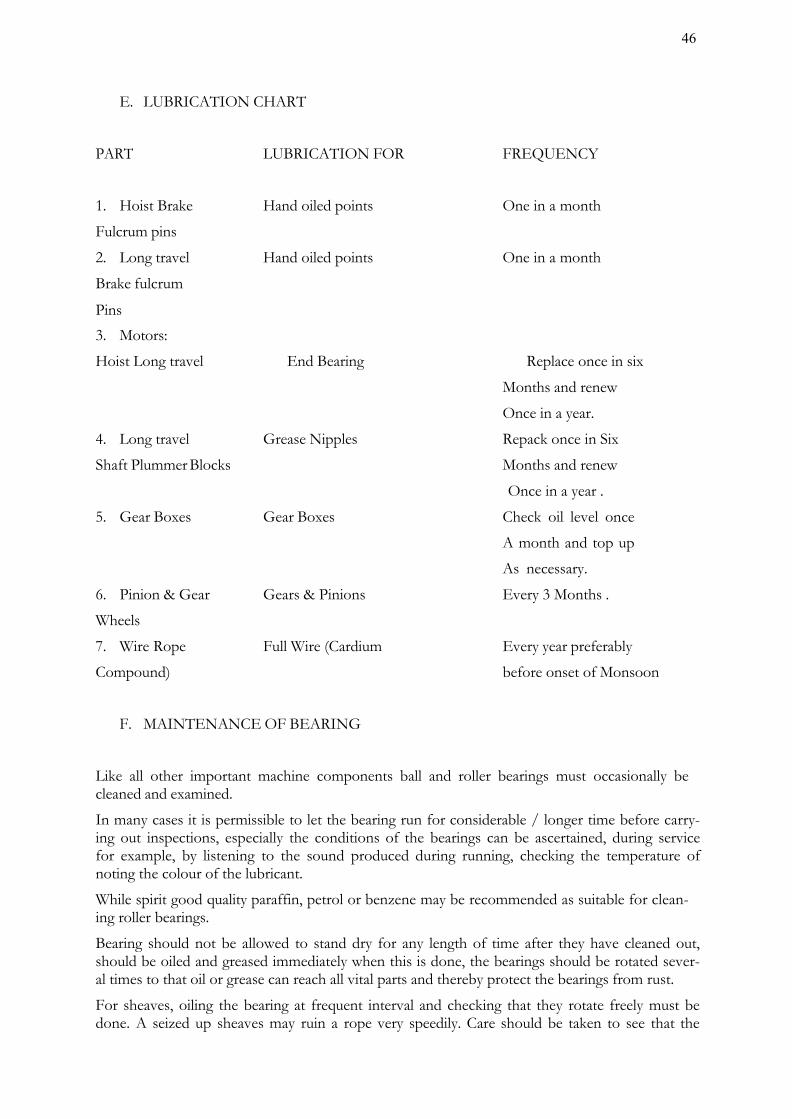
E. LUBRICATION CHART
PART LUBRICATION FOR FREQUENCY
1. Hoist Brake Hand oiled points One in a month
Fulcrum pins
2. Long travel Hand oiled points One in a month
Brake fulcrum
Pins
3. Motors:
Hoist Long travel End Bearing Replace once in six
Months and renew
Once in a year.
4. Long travel Grease Nipples Repack once in Six
Shaft Plummer Blocks Months and renew
Once in a year .
5. Gear Boxes Gear Boxes Check oil level once
A month and top up
As necessary.
6. Pinion & Gear Gears & Pinions Every 3 Months .
Wheels
7. Wire Rope Full Wire (Cardium Every year preferably
Compound) before onset of Monsoon
F. MAINTENANCE OF BEARING
Like all other important machine components ball and roller bearings must occasionally be cleaned and examined.
In many cases it is permissible to let the bearing run for considerable / longer time before carry- ing out inspections, especially the conditions of the bearings can be ascertained, during service for example, by listening to the sound produced during running, checking the temperature of noting the colour of the lubricant.
While spirit good quality paraffin, petrol or benzene may be recommended as suitable for clean- ing roller bearings.
Bearing should not be allowed to stand dry for any length of time after they have cleaned out, should be oiled and greased immediately when this is done, the bearings should be rotated sever- al times to that oil or grease can reach all vital parts and thereby protect the bearings from rust.
For sheaves, oiling the bearing at frequent interval and checking that they rotate freely must be done. A seized up sheaves may ruin a rope very speedily. Care should be taken to see that the
46

rope does not foul in flat against any obstacle in its way.
G. MAINTENANCE OF WIRE ROPE
Frequently the inspection of the entire length of rope is necessary. Watch constantly for broken wires, excessive wear and lubrication, see that the number of broken wires does not exceed as laid down in different regulation.
Prompt attention must be given to a broken wire in a rope otherwise damage to other wires and serious accidents may results.
Cleaning wire rope with brush or compressed air and giving it a light coating of special wire rope dressing is essential. This lubricant puts a protective film on each individual wire, repels water and stops corrosion.
H. CHECK FOR THE TIGHTNESS OF THE BOLTS
1. Fixing bolts of motor and reduction gears.
2. Plummer Block base Bolts.
3. Bolts of all Coupling.
4. Inspect the keys in the Couplings for its correct position once in every six months .
5. The wire Rope and is fixed over the winding drum by weans of clamps and bolts. Theseare to be checked for its tightness periodically.
ADDITIONAL MAINTENANCE ITEMS FOR STOPLOGS
The stop log units being in pieces, the top non-interchangeable unit with unique fea- tures as well as the other interchangeable units are stored in the grooves in various spans / bays. The following aspects are to be considered and attended to during maintenance:
1. Defective / damaged / cracked welding should be cutout and re-welded.
2. Damaged nuts, bolts, screws etc. should be replaced.
3. The gate leaf should be thoroughly cleaned and repainted whenever necessary
4. Rubber seals should be ground, if required to bring it in to alignment. All nutsand bolts for fixing seals to gate should be tightened uniformly. Seals when dam- aged or found leaking excessively should be adjusted or replaced as and whenconsidered necessary.
5. All components should be greased and lubricated with the recommended oil andgrease only.
6. The roller assembly should be adjusted by the eccentricity provision to ensurethat all the rollers rest uniformly on track plates particularly in the closed positionof the stop log gate.
7. The drain holes in horizontal girders should be cleaned.
8. It should be ensured that no bearing is overheated.
9. The gate slots should be kept cleaned. The scaling over the embedded partsshould be removed.
Since normally the stop logs remain in hanging position, for any routine maintenance, these are required to be raised up to the top of pier or deck level to rest on the dogging beam with the help of the gantry crane and lifting beam. Thereafter, if required, it is further raised at a slow speed from safety point of view, it is to be ensured that these units do not foul or hit legs / columns of the gantry crane. Thereafter, the gate can be rested on the deck level for necessary maintenance, servicing, repairs or replacement of its component parts. After completion of maintenance, the stop log units are shifted back to their original dogged position.
47

I. LIFTING BEAM
Lifting beam is used for both raising& lowering of Spillway stop log units with the use of Gantry crane. Lifting Beam shall mainly comprise of two number structural steel channels or fabricated channels with back to back connection to make it a single fabricated structural frame. Two side guide rollers/shoes shall be provided on each side of the lifting beam. The depth of lifting beam /frame should be sufficient to accommodate to rollers on each side located at sufficient distance from one another to enable proper guided movement. The depth of lifting beam shall not be less than one tenth of the length / span of the lifting beam or 500 mm whichever is more.
Lifting beam hook mechanism shall provide for automatic engagement and release of the equipment to be handled manually by movement of the hook block. The two hooks shall be me- chanically linked together for simultaneous operation. All rotating parts of the lifting beam shall be provided with corrosion resistant steel pins and aluminum bronze bushing /roller bearings. All nuts, bolts and washers and retaining devices for pins shall be of corrosion resistant steel.
Following issues need to be considered and attended to during maintenance;
1. Bush bearing of lifting attachment and various pulleys /sheaves wheel gears etc. shouldbe properly lubricated.
2. Whenever it is felt that friction in the bearing has increased, these should be taken outfor cleaning and lubrication and should be refitted properly. These should be replaced, iffound beyond repair.
MAINTENANCE OF BEARING
Like all other important machine components ball and roller bearings must occasionally be cleaned and examined.
In many cases it is permissible to let the bearing run for considerable / longer time before carry- ing out inspections, especially the conditions of the bearings can be ascertained, during service for example, by listening to the sound produced during running, checking the temperature of noting the colour of the lubricant.
While spirit good quality paraffin, petrol or benzene may be recommended as suitable for clean- ing roller bearings.
Bearing should not be allowed to stand dry for any length of time after they have cleaned out, should be oiled and greased immediately when this is done, the bearings should be rotated sever- al times to that oil or grease can reach all vital parts and thereby protect the bearings from rust.
For sheaves, oiling the bearing at frequent interval and checking that they rotate freely must be done. A seized up sheaves may ruin a rope very speedily. Care should be taken to see that the rope does not foul in flat against any obstacle in its way.
4.2 Surface Preparation and Painting of HM Works i) Protection of painted surfaces is considered essential for protection & enhancement of ser-
vice life. Gates, their embedded parts, gate leaf, hoists and its supporting structures need to be protected against corrosion due to climatic condition, weathering, biochemical reaction and abrasion etc. This equipment is likely to deteriorate or get damaged to any extent that the replacement of parts may become necessary and such replacement may become difficult and costly.
ii) Surface preparation & Painting requirements:
Painting for hydro-mechanical works is to be carried out as prescribed in IS 14177 for both new- ly manufactured as well as old & used gates, hoists and associated works after proper surface preparation. The preparation includes thorough cleaning, smoothing irregular surfaces, rust- ed surfaces, weld spatters, oil, grease, dirt, earlier applied damaged layers of primers/ paint by
48

use of mechanical tools, by use of solvents, wire brush etc. The sand / grit blasting process is used for surface preparation to a level of Sa 2½ of the Swedish standard.
iii) Surfaces not requiring painting & their protection during surface preparation, paint- ing & transportation process:
a) The following surfaces are not to be painted unless or otherwise specified:
• Machine finished or similar surface
• Surfaces which will be in contact with concrete
• Stainless steel overlay surfaces.
• Surfaces in sliding or rolling contact
• Galvanized surfaces, brass and bronze surfaces.
• Aluminum alloy surfaces
b) The Surfaces of stainless steel, nickel, bronze and machined surface adjacent to metalwork being cleaned or painted shall be protected by using sticky protective tape or byother suitable means over the surfaces not to be painted.
c) All embedded parts which come in contact with concrete shall be cleaned as detailedabove and given two coats of cement latex to prevent rusting during the shipment while awaiting installation.
iv) Application of primer &finish coats on embedded parts and gates:
a) EMBEDDED PARTS:
• The prescribed primer shall be applied as soon as the surface preparation is completeand prior to the development of surface rusting and within the specified time pre- scribed by Indian Standards or the Paint Manufacturer. In case there is lapse of con- siderable time beyond the prescribed time limit, the surfaces shall be again cleanedprior to priming.
• Two coats of zinc rich primer with epoxy resin shall be applied to all embedded partssurfaces which are not in contact with concrete and shall remain exposed to atmos- phere or submerged in water to obtain a dry film thickness of 75 microns.
• This shall be followed by three coats at an interval of 24hours of coal-tar blend epoxyresin so as to get a dry film thickness of 80 microns in each coat. Total dry filmthickness of paint shall not be less than 300 microns.
b) GATES:
Primer Coat:
• Over the prepared surface one coat of inorganic zinc silicate primer giving a dry filmthickness of 70 ± 5 microns should be applied. Alternatively two coats of zinc richprimer, which should contain not less than 85% zinc on dry film should be applied togive a total dry film thickness of 75 ± 5 microns.
Finished paint:
• Two coats of solvent less coal tar epoxy paints. These shall be applied at an intervalof about 24 hours. Each coat shall give a dry film thickness of 150±5 microns. Thetotal dry film thickness of all the coats including primer coating shall not be less than350 microns.
v) Hoist and supporting structure:
a) Structural components:
49

Primer coats of zinc phosphate primer shall be applied to give a dry film thickness of 40±5 microns.
Final Coats: One coat of alkalized based micaceous iron oxide paint to give a dry film thickness of 65 ± 5 microns followed by two coats of synthetic enamel paint confirming to IS 2932 - 1974 to give a dry film thickness of 25 ± 5 microns per coat. The interval be- tween each coat shall be 24hours. The total dry thickness of all coats of paint including the primer coat shall not be less than 175 microns.
b) Machinery: Except machined surfaces all sur- faces of machinery including gearing, housing,shafting, bearing pedestals etc., shall be given:
Primer coats: One coat of zinc phosphate primer paint to give minimum film thicknessof 50 microns. Motors and other bought out items shall be painted if necessary.
Applied Finished coats: The finished paint shall consists of three coats of aluminum paintconfirming to IS2339 - 1963 or synthetic enamel paint confirming to IS 2932 - 1977 to give a dryfilm thickness of 25± 5 microns per coat to obtain a total minimum dry film thickness of 125 microns.
c) Machined surfaces:
All machined surfaces of ferrous metal including screw threads which will be expo sed duringshipment or installation shall be cleaned by suitable solvent and given a heavy uniform coat-ing of gasoline soluble removable rust preventive compound or equivalent. Machined surfac- esshall be protected with the adhesive tapes or other suitable means during the cleaning andpainting operation of other components .
vi) Application of paint:
Mix the contents thoroughly as directed by paint manufacturer before and during use.
Painting at shop can be done by any of the three methods namely Brush / roller, Conven- tional spray, Airless spray etc.
The paint can be made to suit the adopted method. But once the gate and equipment is in erect- ed position the general method adopted is only brush / roller. In case of spray lot of precautions are to be taken.
For More details: Refer IS: 14177 Part (II) – 1971.
Appendix A – Brushing of paint
Appendix B – Spraying of paint
Appendix C – Spray painting defects: Causes and remedies.
Removal of old paint / rust and carrying out fresh painting:
The carrying out of fresh painting is to be considered under the following conditions:
• The rusting is noticed all over the surface or
• Rusting is severe or
• Cracking and blistering has damaged the primer coat exposing the metal and is noticedall over the surface or
• The paint film has eroded badly, the scrap of entire paint film to the base metal andcarry out fresh painting.
Note: In case of maintenance and renovation: Refer IS 14177 (Part II) – 1971 for checking and repainting.
vii) Removal of old paint for repainting:
Caution should be exercised while removing the old paint. The surfaces shall be de-rusted and descaled by either mechanically by one or more of the methods, namely:
50

a) Wire brushing, Scraping, and chipping. Sand papering or cleaning with steel wool orabrasive paper
b) Power tool cleaning
c) Flame cleaning
d) Sand blasting or shot blasting and
e) Chemical rust removal.
Note: The method of application shall be decided based on conditions existing. After clean- ing painting is to be carried out as originally proposed.
Some are painted without removal of old paint and rusting this will amounts to no painting and deteriorate faster than the original one.
viii) Inspection and testing of painting of H. M works:
a) The following steps are involved in inspection of painting:
• General inspection before and during painting
• Viscosity test of paints
• Paint thickness test – using Elcometer.
• Inspection of general appearance of finished work.
b) General:
The aim of inspection and testing is to ascertain whether the recommended practice is being employed correctly during every stage of application and whether the final results fulfill the object of painting. Any test carried out should be of non - destructive nature or, if it is of destructive nature, it should be either restricted to areas which can be restored without marring the general appearances or be such that it is possible to restore easily without necessitating a complete repetition of the work.
c) Inspection of surfaces prior to painting:
Inspection methods will depend on whether it is to be painted for the first time or is to be re- painted.
d) New Works (Not previously painted): The following shall be decided by inspection:
• The method of pre cleaning feasible or recommended;
• The intermediate protective treatments to be applied, if found necessary;
• The final painting schedule and the specifications for the paint for ensuring the particularperformance;
• The method of application, whether by brush, roller or spray.
e) Old Work (Which requires repainting) :
The following shall be decided by inspection:
• Whether the entire existing paint requires removal; and / or
• Whether repainting without paint removal would be adequate.
4.3 Electrical System Electricity is typically used at a dam for lighting and to operate the gates, hoists, recording equipment,
51

and other miscellaneous equipment. It is important that the Electrical system be well maintained, including a thorough check of fuses and a test of the system to ensure that all parts are properly functioning. The system should be free from moisture and dirt, and wiring should be checked for corrosion and mineral deposits.
All necessary repairs should be carried out immediately and records of the works kept. Maintain genera tors used for auxiliary emergency power -- change the oil, check the batteries and antifreeze and make sure fuel is readily available.
Monitoring devices usually do not need routine maintenance. Open areas are particularly susceptible to vandalism. As such all electrical fittings like bulbs, lights, loose wires etc. in open areas should be checked routinely and replaced / repaired where needed. The recommendations of the manufacturer should also be referred to.
4.4 Maintenance of Metal Gate Components All exposed, bare ferrous metal of an outlet installation, whether submerged or exposed to air, will tend to rust. To prevent corrosion, exposed ferrous metals must be either appropriately painted (following the paint manufacturer‟s directions) or heavily greased in respect of moving parts & on surfaces like guides & track seats on which there is movement of gates. When areas are repainted, it should be ensured that paint is not applied to gate seats, wedges, or stems (where they pass through the stem guides), or on other friction surfaces where paint could cause binding. Heavy grease should be applied on friction surfaces to avoid binding. As rust is especial- ly damaging to contact surfaces, existing rust is to be removed before periodic application of grease.
4.5 Access Roads For a dam to be operated and maintained, there must be a safe means of access to it at all times. Access road surfaces must be maintained to allow safe passage of automobiles and any required equipment for servicing the dam in any weather conditions. Routine observations of any cut and fill slopes along the sides of the road should be made. If unstable conditions develop assistance of experienced Engineers/Expert Panels should be obtained and remedial measures initiated.
Drains are required to be provided and maintained along roads to remove surface and subsurface drainage. This will prolong the life of the road and help reduce deterioration from rutting. Road surfacing should be repaired or replaced as necessary to maintain the required traffic loadings. In most cases, specialized contractors will be required to perform this maintenance.
4.6 General Cleaning As already suggested, for proper operation of spillways, sluiceways, approach channels, inlet and outlet structures, stilling basin / energy dissipation arrangements, discharge conduit, dam slopes, trash racks, debris control devices etc., regular and thorough cleaning and removal of debris is necessary. Cleaning is especially important after large floods, which tend to send more debris into the reservoir.
4.7 Materials and Establishment Requirements during Monsoon Period Materials required during monsoon period for both immediate maintenance and preventive maintenance must be stocked in adequate quantities for emergency situations that may arise. Needful instructions in this regard is enclosed in the O&M Manual. At Chulliyar Dam, a 24/7 hour patrol schedule is carried out during monsoon period. At the same time the additional management requirements during monsoon period are enhanced.
52

4.8 General List of Maintenance Records Maintenance records are of utmost importance. Records are kept of all maintenance activities, both immediate and preventive maintenance works. Essential information to be recorded include the following:
• Date and time of maintenance,• Weather conditions,• Type of maintenance,• Name of person, title and / or contractor performing maintenance,• Description of work performed,• Length of time it took to complete the work with dates,• Equipment and materials used, and• Before and after dated photographs.
The data is recorded by the person responsible for maintenance.
4.9 Preparation of O&M budget In order to prepare O&M budget for a dam project all possible costs associated with implemen- tation of O&M Program need to be identified and considered. Typical O&M budget for a pro- ject should essentially include but not limited to the following items:
i) Establishment Cost of Regular Staff - Salaries and allowances, Bonus, MedicalReimbursement, LTC, Leave Encashment, pension benefits, etc. (as applicable).
ii) Establishment Cost of Work charged Staff - Salaries and allowances, Bonus, Medical Re- imbursement, LTC, Leave Encashment, Pension benefits, TA and DA , etc. (as applicable).
iii) Establishment Cost of Daily wage Staff - Salaries and allowances, TA and DA etc. (asapplicable).
iv) Office Expenses – Rent for office, Telephone/Mobile/any other Telecommunicationbills, Electricity bills, water bills, Office stationery, Day to day office requirements.
v) Motor Vehicles - Running and Maintenance cost of inspection vehicles, Cost of hiring ofvehicles as required
vi) Maintenance of Colony - Maintenance of staff quarters, colony roads, Electricity, Sanitaryand Water supply systems etc.
vii) T&P - T&P requirements for offices, colony, works etc. as applicable.
viii) Works -Painting, oiling, greasing, overhauling of HM equipment, Repair/replacement ofgates seals & wire ropes, POL for pumps & generator sets, Electricity charges andmaintenance of Electric systems of dam site, specific requirements for all Civil, H.M &Electrical maintenance works, vegetation removal and mowing of turfing on earth dams,maintenance/cleaning of drains in dam, maintenance of lift/elevators in dam (as applicable),maintenance of access roads & basic facilities, provision for flood contingency works duringmonsoon, unforeseen events/items (about 10% of the cost of works) etc.
53

Table 23 - O&M BUDGET COSTS (ANNUAL)
SL. NO. BUDGET ITEM
PREVIOUS YEAR COST
(Rs)
CURRENT YEAR BUDG-
ET (YR )
(Rs)
REMARKS
A. ESTABLISHMENT
1 SALARY OF REGULAR STAFF
INCLUDING ALL OTHER BENEFITS
2 TRAVEL EXPENSES
3 OFFICE EXPENSES
4 MOTOR VEHICLE EXPENSES
5 MAINTENANCE OF OFFICE & COLONY COMPLEX
SUB-TOTAL - A
B. WORKS
1 CIVIL
1.1 CONCRETE / MASONRY DAM
1.2 EARTHEN DAM
1.3 INTAKE / OUTLETS IN EARTHEN DAMS
1.4 SLUICES IN CONCRETE / MA- SONRY DAMS
1.5 APPROACH / INSPECTION ROADS WITHIN DAM AREA
2 HYDRO-MECHANICAL
2.1 SPILLWAY GATES & HOISTS
2.2 SPILLWAY STOP-LOG & GAN- TRY CRANE
54

2.3 OUTLETS IN EARTHEN DAMS
- SERVICE / EMERGENCYGATES & HOISTS
2.4
SLUICES IN CONCRETE / MA- SONRY DAMS – SERVICE /
EMERGENCY GATES & HOISTS
3 ELECTRICAL
3.1 ELECTRICAL FITTINGS, MO-
TORS, CONTROLS FOR ALL GATE HOISTS
3.2 POWER SUPPLY LINES
3.3 ELECTRICAL FITTINGS ON
DAM TOP, DAM GALLERIES, ETC.
3.4 STANDBY POWER / DIESEL GENERATOR
3.4 REMOTE CONTROL/CCTV
4 INSTRUMENTATION
5 MISCELLANEOUS WORKS
6 SALARY OF WORK- CHARGED STAFF IN- CLUDING ALL BENEFITS
7 MATERIALS TO BE STORED BEFORE MON- SOON
SUB-TOTAL - B
8 CONTINGENCY (10%) ON SUB-TOTAL OF A & B
9 TOOLS & PLANTS
SUB-TOTAL- C
10 TOTAL ANNUAL COST
55

4.10 Maintenance Records Maintenance records are of utmost importance. A record shall be kept for all maintenance activities, both immediate and preventive maintenance works. Information that must be recorded includes, but not limited to, the following:
• date and time of maintenance,
• weather conditions,
• the type of maintenance,
• name of person or contractor performing maintenance,
• description of work performed,
• the length of time it took to complete the work with dates,
• equipment and materials used, and
• before and after photographs.
56

CHAPTER 5 UPDATING THE MANUAL
As features of the dam and appurtenant structures change occasionally, the O&M Manual must be edited and portions rewritten to reflect these changes. This important task is often ignored. Updating information in the O&M Manual should be done whenever major changes like construction of an additional spillway, construction of dam on the upstream etc. take place. Aspects to be considered when updating include:
• Increase/decrease in the frequency of an inspection or the maintenance routine based onadditional data/ experience acquired.
• Changes in the operation and/or maintenance procedures based on additional da- ta/experience acquired.
• Alterations to the project data because of changes/modifications in the dam by way ofadditional spillway etc.
All up-dates/revisions of the O&M Manual need to be sent to all the locations/addresses to whom the copies of the original O&M Manual had been sent earlier. It is recommended that O&M Manuals be reviewed/ updated after every 10 years by the respective Dam Owners.
57

Appendix 1 – Basic Drawings of Chulliyar Dam
58

GLOSSARY
Dam – any artificial barrier including appur- tenant works constructed across rivers or tributaries thereof with a view to impound or divert water; includes barrage, weir and similar water impounding structures but does not include water conveyance struc- tures such as canal, aqueduct and navigation channel and flow regulation structures such as flood embankments, dikes, and guide bunds.
Dam failure – failures in the structures or operation of a dam which may lead to the uncontrolled release of impounded water resulting in downstream flooding affecting the life and property of the people.
Dam incident – all problems occurring to a dam that has not degraded into „dam failure‟ and including the following:
Structural damage to the dam and appurtenant works;
Unusual readings of instruments in the dam;
Unusual seepage or leakage through the dam body;
Change in the seepage or leakage regime;
Boiling or artesian conditions noticed below an earth dam;
Stoppage or reduction in seepage or leakage from the foundation or body of the dam into any of the galleries, for dams with such galleries;
Malfunctioning or inappropriate operation of gates;
Occurrence of any flood, the peak of which exceeds the available flood dis- charge capacity or 70% of the ap- proved design flood;
Occurrence of a flood, which resulted in encroachment on the available free- board, or the adopted design freeboard;
Erosion in the near vicinity, up to five hundred meters, downstream of the spillway, waste weir, etc.; and Any other event that prudence suggests would have a significant unfavorable impact on dam safety.
Dam inspection – on-site visual examina- tion of all components of dam and its ap- purtenances by one or more persons trained in this respect and includes investigation of the non-overflow portion, spillways, abut- ments, stilling basin, piers, bridge, down- stream toe, drainage galleries, operation of mechanical systems (including gates and its components, drive units, cranes), interior of outlet conduits, instrumentation records, and record-keeping arrangements.
Dam owner – the Central Government or a State Government or public sector under- taking or local authority or company and any or all of such persons or organizations, who own, control, operate or maintain a specified dam.
Dam safety – the practice of ensuring the integrity and viability of dams such that they do not present unacceptable risks to the public, property, and the environment. It requires the collective application of engi- neering principles and experience, and a phi- losophy of risk management that recognizes that a dam is a structure whose safe function is not explicitly determined by its original
59

design and construction. It also includes all actions taken to identify or predict deficien- cies and consequences related to failure, and to document, publicize, and reduce, elimi- nate, or remediate to the extent reasonably possible, any unacceptable risks.
Decommission― Taking a dam out of ser- vice in an environmentally sound and safe manner or converting it to another purpose.
Design life― the intended period that the dam will function successfully with only routine maintenance; determined during design phase.
Distress condition – the occurrence or po- tential development of such conditions in the dam or appurtenance or its reservoir or reservoir rim, which if left unattended to, may impede the safe operation of dam for its intended benefits or may pose unac- ceptable risks to the life and property of people downstream.
Documentation – all permanent records concerning investigation, design, construc- tion, operation, performance, maintenance and safety of dams and includes design memorandum, construction drawings, geo- logical reports, reports of specialized studies simulating structural and hydraulic response of the dam, changes made in design and drawings, quality control records, emergency action plan, operation and maintenance manual, instrumentation readings, inspec- tion and testing reports, operational reports, and dam safety review reports;
Emergency Action Plan(EAP)― a plan of action to be taken to reduce the potential for damage to property and loss of life in the area affected by failure of a dam or other potentially hazardous practice.
Hazard Classification― a system that cat- egorizes dams according to the degree of adverse incremental consequences of a fail- ure or improper operation of the dam. CWC classifies dam hazards as “low”, “signifi- cant”, or “high”.
Maintenance― the recurring activities nec- essary to retain or restore a dam in a safe and functioning condition, including the management of vegetation, the repair or re- placement of failed components, the pre- vention or treatment of deterioration, and the repair of damages caused by flooding or vandalism.
Operation― the administration, manage- ment, and performance of maintenance ac- tivities necessary to keep a dam safe and functioning as planned.
Program ― any authorized activity used to implement and carry out goals, actions, and objectives contained within the authorizing legislation.
Program Life― the period in a contract, conservation plan, or plan during which the conservation practice or conservation sys- tem shall be maintained and used for the intended purpose; determined by program requirements.
Rehabilitation― the completion of all work necessary to extend the service life of the practice or component and meet appli- cable safety and performance standards.
Repair― actions to restore deteriorated, damaged, or failed dam or its component to an acceptable by meeting functional condi- tion.
Replacement― the removal of a structure or component and installation of a similar, functional structure or component.
Service Life― the actual period after con- struction of a dam, during which the prac- tice functions adequately and safely with only routine maintenance; determined by on-site review.
60

Abutment―that part of a valley side against which a dam is constructed. Right and left abutments are those on respective sides of the of an observer looking downstream.
Air-Vent Pipe―a pipe designed to provide air to the outlet conduit to reduce turbu- lence during release of water and safeguard against damages due to cavitation.
Appurtenant Structures―ancillary features of a dam, such as the outlet, spillway, energy dissipation arrangement powerhouse, tun- nels, etc.
Arch Dam―a concrete or masonry dam that is curved to transmit the major part of the water pressure to the abutments.
Backwater Curve―the longitudinal profile of the water surface in an open channel where the depth of flow has been increased by an obstruction, an increase in channel roughness, a decrease in channel width, or a flattening of the bed slope.
Base Width (Base Thickness)―the max- imum width or thickness of a dam measured horizontally between upstream and down- stream faces and normal (perpendicular) to the axis of the dam but excluding projec- tions for outlets, etc.
Berm―a horizontal step or bench in the sloping profile of an embankment dam.
Upstream Blanket―an impervious layer placed on the reservoir floor upstream of a dam. In case of an embankment dam, the blanket may be connected to the impermea- ble element in a dam.
Buttress dam―a dam consisting of a water- tight upstream face supported at intervals on the downstream side by a series of but- tresses.
Cofferdam―a temporary structure enclos- ing all or part of a construction area so that construction can proceed in a dry area.
Concrete Lift―in concrete works the verti- cal distance between successive horizontal construction joints.
Conduit Outlet Works―a closed conduit for conveying discharge through or under a dam for different project purposes.
Consolidation Grouting (Blanket Grout- ing) ― the injection of grout to consolidate a layer of the foundation, resulting in greater impermeability, strength, or both.
Construction Joint―the interface between two successive placings or pours of concrete where a bond, not permanent separation, is intended.
Core Wall―a wall built of impervious mate- rial, usually concrete or asphaltic concrete, in the body of an embankment dam to pre- vent leakage.
Crest Length―the length of the dam at its crest (dam top) top of a dam, including the length of the spillway, powerhouse, naviga- tion lock, fish pass, etc., where these struc- tures form part of the length of a dam. If detached from a dam, these structures should not be included.
Crest of dam―Used to indicate the “top of dam”. To avoid confusion to indicate the crest of spillway and top of dam may be used.
Culvert―a drain or waterway built under a road, railway, or embankment, usually con- sisting of a pipe or covered conduits
61

Cutoff―an impervious construction or ma- terial which reduces seepage through the foundation material.
Cutoff trench―an excavation later to be filled with impervious material to form a cutoff.
Cutoff wall―a wall of impervious material (e.g., concrete, asphaltic concrete, steel-sheet piling) built into the foundation to reduce seepage under the dam.
Dead storage―the storage that lies below the invert of the lowest outlet and that, therefore, cannot be withdrawn from the reservoir.
Design flood―see spillway design flood.
Diaphragm―see membrane.
Dike (Levee)―a long low embankment whose height is usually less than 5 m and whose length is more than 10 times the maximum height. Usually applied to em- bankments or structures built to protect land from flooding. If built of concrete or masonry, the structure is usually referred to as a flood wall. Also, used to describe em- bankments that block areas on a reservoir rim that are lower than the top of the main dam and that are quite long. In the Missis- sippi River basin, where the old French word levee has survived, the term now ap- plies to flood-protecting embankments whose height can average up to 15 m.
Diversion channel, canal, or tunnel―a waterway used to divert water from its natu- ral course. These terms are generally applied to temporary structures such as those de- signed to bypass water around a dam site during construction. “Channel‟ is normally used instead of “canal” when the waterway is short. Occasionally these terms are ap- plied to permanent structures.
Drainage area―an area that drains natural- ly to a point on a river.
Drainage layer or blanket―a layer of per- meable material in a dam to relieve pore pressure or to facilitate drainage of fill.
Relief well―vertical wells or boreholes, constructed downstream of an embankment dam to relieve the pressure from confined pervious layers in foundation overlaid by an impervious layer to arrest boiling.
Drawdown―the lowering of water surface level due to release of water from a reser- voir.
Earthen dam or earth filled dam―see em- bankment dam.
Embankment dam (Fill dam)― any dam constructed of excavated natural materials.
Earth dam (Earth fill dam)―An em- bankment dam in which more than 50 per- cent of the total volume is formed of com- pacted fine-grained material obtained from a borrow area.
Homogeneous earth fill dam― an em- bankment dam constructed of similar earth material throughout, except internal drains or drainage blankets; distinguished from a zoned earth fill dam.
Hydraulic fill dam―an embankment dam constructed of materials, often dredged, that are conveyed and placed by suspension in flowing water.
Rock fill dam―an embankment dam in which more than 50 percent of the total volume comprises compacted or dumped pervious natural or crushed rock.
62

Rolled fill dam―an embankment dam of earth or rock in which the material is placed in layers and compacted using rollers or roll- ing equipment.
Zoned embankment dam―an embank- ment dam composed of zones of materials selected for different degrees of porosity, permeability and density.
Emergency spillway―see spillway.
Face―the external surface of a structure, e.g., the surface of a wall of a dam.
Failure―the uncontrolled release of water from a dam.
Filter (filter zone)―A band or zone of granular material that is incorporated into a dam and is graded (either naturally or by selection) to allow seepage to flow across or down the filter without causing the migra- tion of material from zones adjacent to it.
Flashboards―a length of timber, concrete, or steel placed on the crest of a spillway to raise the retention water level but that may be quickly removed in the event of a flood, either by a tripping device or by deliberately designed failure of the flashboard or its supports.
Floodplain―an area adjoining a body of water or natural stream that has been, or may be, covered by flood water.
Floodplain management―a management program to reduce the consequences of flooding, either by natural runoff or by dam failure, to existing and future properties in a floodplain.
Flood routing―the determination of the attenuating effect of storage on a flood pass- ing through a valley, channel, or reservoir.
Flood surcharge―the volume or space in a reservoir between the controlled retention water level (Full Reservoir Level) and the maximum water level. Flood surcharge can- not be retained in the reservoir but will flow over the spillway until the controlled reten- tion water level is reached.
Flood wall―a concrete wall constructed adjacent to a stream to prevent flooding of property on the landward side of the wall, normally constructed in lieu of or to sup- plement a levee where the land required for levee construction is expensive or not avail- able.
Foundation of dam―the natural material on which the dam structure is placed.
Freeboard―the vertical distance between a stated reservoir level and the top of a dam. Normal freeboard is the vertical distance between Full Reservoir Level (FRL) and the top of the dam. Minimum freeboard is the
vertical distance between the Maximum Wa- ter Level (MWL) and the top of the dam.
Gallery―(a) a passageway within the body of a dam or abutment, hence the terms grout- ing gallery, inspection gallery and drainage gallery
(b) a long and rather narrow hall, hence the following terms for a power plant viz. valve gallery, transformer gallery and bus bar gallery.
Gate―a device in which a leaf or member is moved across the waterway from an external position to control or stop the flow.
Bulkhead gate―a gate used either for tem- porary closure of a channel or conduit to empty it for inspection or maintenance or for closure against flowing water when the head difference is
63

small, e.g., for diversion tunnel closure. Although a bulkhead gate is usually opened and closed under nearly bal- anced pressures, it nevertheless may be ca- pable of withstanding a high pressure differ- ential when in the closed position.
Crest gate (spillway gate)―a gate on the crest of a spillway to control overflow or reservoir water level.
Emergency gate―a standby or reserve gate which is lowers only for repairing / servic- ing of the service gate.
Fixed wheel gate (fixed-roller gate, fixed-axle gate)―a gate having wheels or rollers mounted on the end posts of the gate. The wheels move against rails fixed in side grooves or gate guides.
Flap gate―a gate hinged along one edge, usually either the top or bottom edge. Ex- amples of bottom-hinged flap gates are tilt- ing gates and belly gates, so called due to their shape in cross-section.
Flood gate―a gate to control flood release from a reservoir.
Guard gate(guard valve)―a gate or valve that operates fully open or closed. It may function as a secondary device for shutting off the flow of water in case the primary closure device becomes inoperable but is usually operated under conditions of bal- anced pressure and no flow.
Outlet gate―a gate controlling the outflow of water from a reservoir.
Radial gate (Tainter gate)―a gate with a curved upstream plate and radial arms hinged to piers or other supporting struc- tures.
Service/Regulating gate(regulating valve)―a gate or valve that operates under full pressure and flow to throttle and vary the rate of discharge.
Slide gate (sluice gate)―a gate that can be opened or closed by sliding it in supporting guides.
Gravity dam―a dam constructed of con- crete, masonry, or both that relies on its weight for stability.
Grout cap―a pad or wall constructed to facilitate pressure grouting of the grout cur- tain beneath it.
Grout curtain (grout cutoff)―a barrier produced by injecting grout into a vertical zone, usually narrow horizontally, in the foundation to reduce seepage under a dam.
Height above lowest foundation―the maximum height from the lowest point of the general foundation to the top of the dam.
Hydraulic height―the height to which wa- ter rises behind a dam and the difference between the lowest point in the original streambed at the axis of the dam and the maximum controllable water surface.
Hydrograph―a graphic representation of discharge, stage, or other hydraulic property with respect to time for a point on a stream. (At times the term is applied to the phe- nomenon the graphic representation de- scribes; hence a flood hydrograph is the pas- sage of a flood discharge past the observa- tion point.)
Inclinometer―an instrument, usually con- sisting of a metal or plastic tube inserted in a drill hole and a sensitized monitor either lowered into the tube or fixed within it. The monitor measures at different points the tube‟s inclination to the vertical. By integra- tion, the lateral position at various
64

levels of the tube may be found relative to a point, usually the top or bottom of the tube, as- sumed to be fixed. The system may be used to measure settlement.
Intake―any structure in a reservoir, dam, or river through which water can be drawn into an aqueduct.
Internal Erosion―see piping.
Inundation map―a map delineating the area that would be inundated in case of a failure.
Leakage―Uncontrolled loss of water by flow through a hole or crack.
Lining― a coating of asphaltic concrete, reinforced or unreinforced concrete, shot- crete, rubber or plastic on a canal, tunnel etc. to provide water tightness, prevent ero- sion, reduce friction, or support the periph- ery of structure. May also refer to lining, such as steel or concrete, of outlet pipe or conduit.
Low-level outlet (bottom outlet)―an opening at a low level from a reservoir gen- erally used for emptying or for scouring sed- iment and sometimes for irrigation releases.
Masonry dam―a dam constructed mainly of stone, brick, or concrete blocks that may or may not be joined with mortar. A dam having only a masonry facing should not be referred to as a masonry dam.
Maximum cross-section of dam―a cross- section of a dam at the point of its maxi- mum height.
Maximum water level―the maximum wa- ter level, including flood surcharge, the dam is designed to withstand.
Membrane (Diaphragm)―a sheet or thin zone or facing made of a flexible material, sometimes referred to as a diaphragm wall or diaphragm.
Minimum operating level―the lowest lev- el to which the reservoir is drawn down un- der normal operating conditions.
Morning glory spillway―see spillway.
Full Reservoir Level (FRL)/Normal wa- ter level―for a reservoir with un-gated spillway it is the spillway crest level. For a reservoir, whose outflow is controlled whol- ly or partly by movable gates, siphons or other means, it is the maximum level to which water can be stored under normal operating conditions, exclusive of any provi- sion for flood surcharge.
One-Hundred Year (100-Year) Exceed- ance Interval― the flood magnitude ex- pected to be equaled or exceeded on the average of once in 100 years. It may also be expressed as an exceedance frequency, i.e. a per- cent chance of being exceeded in any given year.
Outlet―an opening through which water can be freely discharged from a reservoir.
Overflow dam―a dam designed to be over- topped.
Parapet Wall―a solid wall built along the top of a dam for ornament, for the safety of vehicles and pedestrians, or to prevent over- topping.
Peak Flow―the maximum instantaneous discharge that occurs during a flood. It co- incides with the peak of a flood hydrograph.
65

Pervious Zone―a part of the cross-section of an embankment dam comprising material of high permeability.
Phreatic Surface―the top most flow line in an embankment dam.
Piezometer―an instrument for measuring pore water pressure within soil, rock, or concrete.
Piping―the progressive development of internal erosion by seepage, appearing downstream as a hole or seam discharging water that contains soil particles.
Pore Pressure―the interstitial pressure of water within a mass of soil, rock, or con- crete.
Pressure Cell―an instrument for measuring pressure within a mass of soil, rock, or con- crete or at an interface between one and the other
Pressure Relief Pipes―Pipes used to re- lieve uplift or pore water pressure in a dam‟s foundation or structure.
Probable Maximum Flood (PMF)―a flood that would result from the most se- vere combination of critical meteorologic and hydrologic conditions possible in the region.
Probable Maximum Precipitation (PMP)―the maximum amount and dura- tion of precipitation that can be expected to occur on a drainage basin.
Pumped storage reservoir―a reservoir filled entirely or mainly with water pumped from outside its natural drainage area.
Regulating dam―a dam impounding a res- ervoir from which water is released to regu- late
Reservoir area―the surface area of a reser- voir when filled to controlled retention lev- el.
Reservoir routing―the computation by which the interrelated effects of the inflow hydrograph, reservoir storage, and discharge from the reservoir are evaluated.
Reservoir surface―the surface of a reser- voir at any level.
Riprap―a layer of large stones, broken rock, or precast blocks placed randomly on the upstream slope of an embankment dam, on a reservoir shore, or on the sides of a channel as a protection against wave action. Large riprap is sometimes referred to as ar- moring.
Risk assessment―as applied to dam safety, the process of identifying the likelihood and consequences of dam failure to provide the basis for informed decisions on a course of action.
Rock fill Dam―see embankment dam.
Roll Crete or Roller-Compacted Con- crete A no-slump concrete that can be hauled in dump trucks, spread with a bull- dozer or grader, and compacted with a vi- bratory roller.
Seepage―the interstitial movement of wa- ter that may take place through a dam, its foundation, or its abutments.
Sill―(a) A submerged structure across a riv- er to control the water level upstream. (b) The crest of a spillway. (c) A horizontal gate seating, made of wood, stone, concrete or metal at the invert of any opening or gap in a structure, hence the expressions gate sill and stop log sill.
66

Slope―(a) the side of a hill or mountain. (b) The inclined face of a cutting or canal or embankment. (c) Inclination from the hori- zontal. In the United States, it is measured as the ratio of the number of units of hori- zontal distance to the number of corre- sponding units of vertical distance. The term is used in English for any inclination and is expressed as a percentage when the slope is gentle, in which case the term gradient is also used.
Slope Protection―the protection of a slope against wave action or erosion.
Sluiceway―see low-level outlet.
Spillway―a structure over or through which flood flows are discharged. If the flow is controlled by gates, it is a controlled spillway; if the elevation of the spillway crest is the only control, it is an uncontrolled spillway.
Auxiliary Spillway (Emergency Spill- way)―a secondary spillway designed to op- erate only during exceptionally large floods.
Fuse-Plug Spillway―an auxiliary or emer- gency spillway comprising a low embank- ment or a natural saddle designed to be overtopped and eroded away during a rare and exceptionally large flood.
Primary Spillway(Principal Spill- way)―the principal or first-used spillway during flood flows.
Shaft Spillway (Morning Glory Spill- way)―a vertical or inclined shaft into which flood water spills and then is conducted through, under, or around a dam by means of a conduit or tunnel. If the upper part of the shaft is splayed out and terminates in a circular horizontal weir, it is termed a “bell mouth” or “morning glory” spillway.
Side Channel Spillway―a spillway whose crest is roughly parallel to the channel im- mediately downstream of the spillway.
Siphon Spillway―a spillway with one or more siphons built at crest level. This type of spillway is sometimes used for providing automatic surface-level regulation within narrow limits or when considerable dis- charge capacity is necessary within a short period.
Spillway Channel (Spillway Tunnel)―a channel or tunnel conveying water from the spillway to the river downstream.
Stilling Basin―a basin constructed to dis- sipate the energy of fast-flowing water, e.g., from a spillway or bottom outlet, and to protect the riverbed from erosion.
Stop logs―large logs or timber or steel beams placed on top of each other with their ends held in guides on each side of a channel or conduit providing a cheaper or easily handled temporary closure than a bulkhead gate.
Storage―the retention of water or delay of runoff either by planned operation, as in a reservoir, or by temporary filling of over- flow areas, as in the progression of a flood crest through a natural stream channel.
Tailrace―the tunnel, channel or conduit that conveys the discharge from the turbine to the river, hence the terms tailrace tunnel and tailrace canal.
Tail water Level―the level of water in the tailrace at the nearest free surface to the tur- bine or in the discharge channel immediately downstream of the dam.
67

Toe of Dam―the junction of the down- stream face of a dam with the ground sur- face, referred to as the downstream toe. For an embankment dam the junction of upstream face with ground surface is called the up- stream toe.
Top of Dam―the elevation of the upper- most surface of a dam, usually a road or walkway, excluding any parapet wall, rail- ings, etc.
Top Thickness (Top Width)―the thick- ness or width of a dam at the level of the top of the dam. In general, “thickness” is used for gravity and arch dams, “width” for other dams.
Transition Zone (Semi-pervious Zone)―a part of the cross-section of a zoned embankment dam comprising materi- al of intermediate size between that of an impervious zone and that of a permeable zone.
Trash rack―a screen located at an intake to prevent the ingress of debris.
Tunnel―a long underground excavation usually having a uniform cross-section. Types of tunnel include: headrace tunnel, pressure tunnel, collecting tunnel, diversion tunnel, power tunnel, tailrace tunnel, naviga- tion tunnel, access tunnel, scour tunnel, draw-off tunnel, and spillway tunnel.
Under seepage―the interstitial movement of water through a foundation.
Uplift―the upward pressure in the pores of a material (interstitial pressure) or on the base of a structure.
Upstream Blanket―see blanket.
Valve―a device fitted to a pipeline or orifice in which the closure member is either rotat- ed or moved transversely or longitudinally in the waterway to control or stop the flow.
Water stop―a strip of metal, rubber or oth- er material used to prevent leakage through joints between adjacent sections of concrete.
Weir―(a) a low dam or wall built across a stream to raise the upstream water level, called fixed-crest weir when uncontrolled. (b) A structure built across a stream or channel for measuring flow, sometimes called a measuring weir or gauging weir. Types of weir include broad-crested weir, sharp-crested weir, drowned weir, and submerged weir.
68