operation and maintenance manual...caterpillar ® dealers have the ... maintenance listed in the...
TRANSCRIPT

Operation andMaintenanceManual
31200243July 14, 2006
TH360B TelehandlerS/N TBH00100 & After
Keep this manual with machine at all times.

Important Safety InformationMost accidents that involve product operation, maintenance and repair are caused by failure to observe basic safety rules or precautions. An accident can often be avoided by recognizing potentially hazardous situations before an accident occurs. A person must be alert to potential hazards. This person should also have the necessary training, skills and tools to perform these functions properly.
Improper operation, lubrication, maintenance or repair of this product can be dangerous and could result in injury or death.
Do not operate or perform any lubrication, maintenance or repair on this product, until you have read and understood the operation, lubrication, maintenance and repair information.
Safety precautions and warnings are provided in this manual and on the product. If these hazard warnings are not heeded, bodily injury or death could occur to you or to other persons.
The hazards are identified by the "Safety Alert Symbol" and followed by a "Signal Word" such as "DANGER", "WARNING" or "CAUTION". The Safety Alert "WARNING" label is shown below.
The meaning of this safety alert symbol is as follows:
Attention! Become Alert! Your Safety is Involved.
The message that appears under the warning explains the hazard and can be either written or pictorially presented.
Operations that may cause product damage are identified by "NOTICE" labels on the product and in this publication.
Caterpillar cannot anticipate every possible circumstance that might involve a potential hazard. The warnings in this publication and on the product are, therefore, not all inclusive. If a tool, procedure, work method or operating technique that is not specifically recommended by Caterpillar is used, you must satisfy yourself that it is safe for you and for others. You should also ensure that the product will not be damaged or be made unsafe by the operation, lubrication, maintenance or repair procedures that you choose.
The information, specifications, and illustrations in this publication are on the basis of information that was available at the time that the publication was written. The specifications, torques, pressures, measurements, adjustments, illustrations, and other items can change at any time. These changes can affect the service that is given to the product. Obtain the complete and most current information before you start any job. Caterpillar® dealers have the most current information available.
When replacement parts are required for thisproduct Caterpillar recommends usingCaterpillar replacement parts or parts withequivalent specifications including, but notlimited to, physical dimensions, type, strengthand material.
Failure to heed this warning can lead topremature failures, product damage, personalinjury or death.
31200243 1Table of Contents
Table of Contents
ForewordLiterature Information ............................................ 5Safety .................................................................... 5Operation .............................................................. 5Maintenance.......................................................... 5
Maintenance Intervals ...................................... 5Certified Engine Maintenance ............................... 5Machine Capacity.................................................. 5Contact Information ............................................... 6
Safety SectionSafety Messages................................................... 7
Do Not Operate (1)......................................... 10Do Not Stand Under the Load (2) .................. 10No Hands (3).................................................. 11Do Not Operate (4)......................................... 11Forks (5)......................................................... 12Do Not Weld On The ROPS/FOPSStructure (6) ................................................... 12Crushing Hazard (7)....................................... 13No Hands (8).................................................. 13Seat Belt (9) ................................................... 14Crushing Hazard (10)..................................... 14Crushing Hazard (11)..................................... 15Engine Coolant (12) ....................................... 15Avoid Power Lines (13) .................................. 16Low Bridge (14).............................................. 16Jump Start Cables (15) .................................. 17Ether (16) ....................................................... 17Crushing Hazard (17)..................................... 18Crushing Hazard (18)..................................... 18Operation (19) ................................................ 18Impaling Hazard (20)...................................... 18Crushing Hazard (21)..................................... 19Entanglement and Flying Objects (22)........... 19Trap Point (23) ............................................... 19Crushing Hazard (24)..................................... 19Ether (25) ....................................................... 20Additional Messages...................................... 20
General Hazard Information ................................ 24Pressurized Air and Water ............................. 25Trapped Pressure .......................................... 25Fluid Penetration ............................................ 25Containing Fluid Spillage ............................... 25Dispose of Waste Properly............................. 25
Crushing Prevention and Cutting Prevention ...... 25Burn Prevention ............................................. 26Coolant........................................................... 26Oils ................................................................. 26Batteries ......................................................... 26
Fire Prevention and Explosion Prevention .......... 26Fire Extinguisher ............................................ 27Lines, Tubes and Hoses ................................ 27Fire Extinguisher Location.............................. 28Tire Information .............................................. 28Electrical Storm Injury Prevention .................. 28Before Starting Engine................................... 29
Engine Starting.................................................... 29
Before Operation..................................................30Operation .............................................................30
Machine Operating Temperature Range ........30Machine Operation .........................................30Travel..............................................................30Lifting Capacities ............................................30Work Tools......................................................31
Engine Stopping...................................................31Work Tools...........................................................31Parking.................................................................31Equipment Lowering with Loss of HydraulicPower...................................................................32Sound Information and Vibration Information ......32
Sound Level....................................................32Vibration Level ................................................32
Operator Station...................................................32Guards (Operator Protection) ..............................32
Rollover Protective Structure (ROPS), Falling Object Protective Structure (FOPS)................33Other Guards (If Equipped) ............................33
Product Information SectionGeneral Information .............................................35
Lifting Capacities ............................................35Examples of Estimating the Lift Operation from the Load Chart ................................................36
Specifications.......................................................37Intended Use ..................................................38Application/Configuration Restrictions ............38
Identification Information......................................38Plate Locations and Film Locations ................38Serial Number.................................................39Certification.....................................................39Sound .............................................................39ROPS/FOPS Film ...........................................40Machine Security System ...............................40Italian Roading Homologation.........................40
Emissions Certification Film.................................42
Operation SectionBefore Operation..................................................43
Mounting and Dismounting .............................43Alternate Exit ..................................................43Daily Inspection ..............................................43
Machine Operation...............................................45Alternate Exit ..................................................45Seat ................................................................45Air Suspension (If Equipped) ..........................46Seat Belt .........................................................46Operator Controls (Side Console) ..................49Operator Controls ...........................................51Operation Information .....................................67Work Tools......................................................75Monitoring System ..........................................80Backup Alarm .................................................83Cab Door ........................................................84
Engine Starting ....................................................84Engine Starting ...............................................84Starting Below 0 °C (32°F)..............................85Engine and Machine Warm-Up.......................85
Table of

31200243 2Table of Contents
Parking ................................................................ 86Stopping the Machine .................................... 86Stopping the Engine....................................... 86Stopping the Engine if an Electrical Malfunction Occurs............................................................ 86Leaving the Machine...................................... 86
Transportation Information .................................. 87Shipping the Machine..................................... 87Roading the Machine ..................................... 87Lifting and Tying Down the Machine.............. 88
Towing Information.............................................. 88Towing the Machine....................................... 88Types of Towing Hitches................................ 90
Engine Starting (Alternate Methods) ................... 91Engine Starting with Jump Start Cables......... 91Equipment Lowering with Loss of Hydraulic Power ............................................................. 93
Maintenance SectionMaintenance Access ........................................... 97
Access Doors and Covers.............................. 97Tire Inflation Information ..................................... 97
Tire Inflation with Air....................................... 97Tire Pressure.................................................. 98Tire Inflation Pressure Adjustment ................. 99Tire Damage .................................................. 99Tire Replacement........................................... 99Wheel and Tire Installation............................. 99
Lubricant Viscosities and Refill Capacities........ 100Lubricant Viscosities .................................... 100Capacities (Refill) ......................................... 102SOS Information........................................... 103
Maintenance Support ........................................ 103Welding on Machines and Engines with Electronic Controls ....................................... 103
Maintenance Interval Schedule ......................... 104Axle Breathers - Clean/Replace........................ 106Backup Alarm - Test.......................................... 106Battery - Recycle............................................... 106Battery or Battery Cable -Inspect/Replace........ 106Belt - Inspect/Replace ....................................... 107
Inspect ......................................................... 107Replace........................................................ 107
Boom Chain - Inspect/ Lubricate ....................... 108Boom Chain Tension -Check/Adjust ................. 108
Check Condition........................................... 108Check and Adjust the Chain Tension........... 108Measure the Chain for Wear ........................ 109
Boom Cylinder Pin - Lubricate .......................... 110Boom Head Section - Lubricate ........................ 110Boom Pivot Shaft - Lubricate ............................ 110Boom Telescoping Cylinder Air- Purge ............. 110Boom Wear Pad Clearance -Inspect/Adjust...... 111
Adjustment ................................................... 112Boom and Frame - Inspect................................ 113Braking System - Test ....................................... 114
Service Brake............................................... 114Parking Brake............................................... 115
Cab Air Filter - Clean/Replace........................... 115
Primary Cab Air Filter ...................................115Secondary Cab Air Filter...............................116
Circuit Breakers - Test .......................................116Cooling System Coolant - Change.....................117Cooling System Coolant Level - Check .............118Cooling System Coolant Sample (Level 1) -Obtain ................................................................119Cooling System Coolant Sample (Level 2) -Obtain ................................................................119Cooling System Pressure Cap - Clean/Replace 120Cooling System Water Temperature Regulator Replace..............................................................120Differential Oil - Change.....................................121
Rear Axle Differential ....................................121Front Axle Differential ...................................122
Differential Oil Level - Check .............................122Rear Axle Differential ....................................122Front Axle Differential ...................................123
Differential Oil Sample - Obtain .........................123Drive Shaft Spline - Lubricate ............................124Drive Shaft Universal Joint Bolts - Check ..........124Engine Air Filter Primary Element -Clean/Replace ...................................................125
Cleaning Primary Air Filter Elements............125Inspecting the Primary Air Filter Elements....126
Engine Air Filter Secondary Element - Replace.127Engine Air Filter Primary Element - Replace .....127Engine Mounts - Inspect ....................................127Engine Oil Level - Check ...................................127Engine Oil Sample - Obtain ...............................128Engine Oil and Filter - Change...........................128Engine Valve Lash - Check................................129Final Drive Oil - Change.....................................130Final Drive Oil Level - Check .............................130Final Drive Oil Sample - Obtain .........................131Fork Leveling Cylinder Pin -Lubricate ................132Frame Leveling Cylinder Pin -Lubricate.............132Fuel System - Prime ..........................................132Fuel System Secondary Filter Replace..............133Fuel System Water Separator - Drain................133Fuel System Water Separator Element -Replace..............................................................134Fuel Tank Cap - Clean.......................................135Fuel Tank Water and Sediment - Drain .............135Fuses and Relays - Replace..............................136
Fuses ............................................................136Relays...........................................................138
Indicators and Gauges - Test.............................138Longitudinal Stability Indicator - Calibrate..........139Longitudinal Stability Indicator -Test ..................139
Initial Test .....................................................139Second Test..................................................139
Oil Filter - Inspect...............................................139Inspect a Used Filter for Debris ....................139
Parking Brake - Adjust .......................................140Pulley for Boom Extension Chain - Lubricate ....140Pulley for Boom Retraction Chain - Lubricate....140Radiator Core - Clean ........................................141Refrigerant Dryer - Replace ...............................141

3 31200243Table of Contents
Rollover Protective Structure (ROPS) and Falling Object Protective Structure (FOPS) -Inspect .... 142Seat Belt - Inspect ............................................. 142Seat Belt - Replace ........................................... 143Stabilizer and Cylinder Bearings - Lubricate ..... 143Tire Inflation - Check ......................................... 143Transmission and Hydraulic System Oil -Change.............................................................. 144Transmission and Hydraulic System Oil Filter - Replace ............................................................. 145Transmission and Hydraulic System Oil Level - Check ................................................................ 146Transmission and Hydraulic System Oil Sample - Obtain................................................................ 147Transmission and Hydraulic System TankBreather - Clean ................................................ 147Turbocharger - Inspect ...................................... 147Wheel Nut Torque - Check................................ 147Window Washer Reservoir -Fill ......................... 148Window Wiper -Inspect/Replace ....................... 148Windows - Clean ............................................... 148Work Tool - Inspect/Replace ............................. 148
Forks ............................................................ 148Buckets ........................................................ 150
Reference Information Section Approved Work Tools.................................. 153

31200243 4Table of Contents

31200243 5Foreword
Foreword
Literature InformationThis manual should be stored in the operator's compartment in the literature holder or seat back literature storage area.
This manual contains safety information, operation instructions, transportation information, lubrication information and maintenance information.
Some photographs or illustrations in this publication show details or attachments that can be different from your machine. Guards and covers might have been removed for illustrative purposes.
Continuing improvement and advancement of product design might have caused changes to your machine which are not included in this publication. Read, study and keep this manual with the machine.
Whenever a question arises regarding your machine, or this publication, please consult your Caterpillar dealer for the latest available information.
SafetyThe safety section lists basic safety precautions. In addition, this section identifies the text and locations of warning signs and labels used on the machine.
Read and understand the basic precautions listed in the safety section before operating or performing lubrication, maintenance and repair on this machine.
OperationThe operation section is a reference for the new operator and a refresher for the experienced operator. This section includes a discussion of gauges, switches, machine controls, attachment controls, transportation and towing information.
Photographs and illustrations guide the operator through correct procedures of checking, starting, operating and stopping the machine.
Operating techniques outlined in this publication are basic. Skill and techniques develop as the operator gains knowledge of the machine and its capabilities.
MaintenanceThe maintenance section is a guide to equipment care. The Maintenance Interval Schedule (MIS) lists the items to be maintained at a specific service interval. Items without specific intervals are listed under the "When Required" service interval. The Maintenance Interval Schedule lists the page number for the step-by-step instructions required to accomplish the scheduled maintenance. Use the Maintenance Interval Schedule as an index or "one safe source" for all maintenance procedures.
Maintenance IntervalsUse the service hour meter to determine servicing intervals. Calendar intervals shown (daily, weekly, monthly, etc.) can be used instead of service hour meter intervals if they provide more convenient servicing schedules and approximate the indicated service hour meter reading. Recommended service should always be performed at the interval that occurs first.
Under extremely severe, dusty or wet operating conditions, more frequent lubrication than is specified in the maintenance intervals chart might be necessary.
Certified Engine MaintenanceProper maintenance and repair is essential to keep the engine and machine systems operating correctly. As the heavy duty off-road diesel engine owner, you are responsible for the performance of the required maintenance listed in the Owner Manual, Operation and Maintenance Manual, and Service Manual.
It is prohibited for any person engaged in the business of repairing, servicing, selling, leasing, or trading engines or machines to remove, alter, or render inoperative any emission related device or element of design installed on or in an engine or machine that is in compliance with the regulations (40 CFR Part 89). Certain elements of the machine and engine such as the exhaust system, fuel system, electrical system, intake air system and cooling system may be emission related and should not be altered unless approved by Caterpillar.
Machine CapacityAdditional attachments or modifications may exceed machine design capacity which can adversely affect performance characteristics. Included would be stability and system certifications such as brakes, steering, and rollover protective structures (ROPS). Contact your Caterpillar dealer for further information.

6 31200243Foreword
Contact InformationFor:
• Accident Reporting and Product Safety Publications
• Current Owner Updates
• Questions Regarding Product Applications andSafety
• Standards and Regulations Compliance Information
• Questions Regarding Product Modifications
Contact:
Product Safety and Reliability DepartmentJLG Industries, Inc.1 JLG DriveMcConnellsburg, PA 17233USA
or Your Local JLG Office
In USA:Toll Free: 877-JLG-SAFE (877-554-7233)
Outside USA:Phone: 717-485-5161 or 717-485-6591
E-mail: [email protected]

31200243 7Safety Section
Safety Section
Safety Messages
Illustration 2 g01106084

8 31200243Safety Section
Illustration 3 g01213315

31200243 9Safety Section
Illustration g01213316
Illustration 5 g01213318
There are several specific safety messages on these machines. The exact location of the messages and the description of the messages are reviewed in this section. Please become familiarized with all safety messages.
Make sure that all of the safety messages are legible. Clean the safety messages or replace the safety messages if you cannot read the words. Replace the illustrations if the illustrations are not legible. When you clean the safety messages, use a cloth, water and soap. Do not use solvent, gasoline, or other harsh chemicals to clean the safety messages. Solvents, gasoline, or harsh chemicals could loosen the adhesive that secures the safety message. Loose adhesive will allow the safety message to fall.
Replace any safety message that is damaged, or missing. If a safety message is attached to a part that is replaced, install a safety message on the replacement part. Any Caterpillar dealer can provide new safety messages.

10 31200243Safety Section
Do Not Operate (1)This safety message is positioned on the panel at the right side of the operator station.
g00931194
Do not operate or work on this equipment unless youhave read and understand the instructions andwarnings in the Operation and Maintenance Manual.Failure to follow the instructions or heed the warningscould result in injury or death. Contact any Caterpillardealer for replacement manuals. Proper care is yourresponsibility.
Do Not Stand Under the Load (2)This message is positioned on the side of the boom head on both sides of the machine
g00930659
A crushing hazard exists when the boom is lowered orfrom a falling load. Stay clear of the boom when themachine is in operation. Failure to stay clear of theboom can cause injury or death.

31200243 11Safety Section
No Hands (3)The message is positioned on the side of the number one boom section on both sides of the machine
g00930870
A crushing hazard exists when the boom sections arebeing retracted or extended. Stay clear of the boomwhen the machine is in operation. Failure to stay clear ofthe boom when the machine is operation can causeinjury or death.
Do Not Operate (4)This safety message is located on the front dash in the operator compartment.
g00936539
Improper operation or maintenance of the machinecould result in injury or death. Do not operate orwork on this machine unless you have been properlytrained and authorized and have read and understoodthe warnings and instructions in the Operation andMaintenance Manual.
Refer to Operation and Maintenance Manual, "Load Charts" for more information.

12 31200243Safety Section
Forks (5)This safety message is positioned on the panel at the right side of the operator station.
g01059274
Side loading of the forks may cause premature failureof the forks and thus a crush hazard which may causepersonal injury or death. Never push loads with theforks and inspect the forks daily for any twisting orbending observed in the forks. Should twisting orbending be observed, change the fork(s) prior to anylifting operation. Read the Operation and MaintenanceManual for more information about the correct use ofthe forks.
Do Not Weld On The ROPS/FOPS Structure (6)This safety message is positioned behind the seat near the window.
g01211890
Structural damage, an overturn, modification,alteration, or improper repair can impair thisstructure's protection capability thereby voiding thiscertification. Do not weld on or drill holes in thestructure. This will void the certification. Consult aCaterpillar dealer to determine this structure'slimitations without voiding its certification.
This machine has been certified to the standards that are listed on the certification film. The maximum mass of the machine, which includes the operator and the attachments without a payload, should not exceed the mass on the certification film.
A typical example of the warning film and certification film are shown above.
Refer to Operation and Maintenance Manual, "Guards (Operator Protection)" for more information.

31200243 13Safety Section
Crushing Hazard (7)The message is positioned on the underside of the stabilizer beam on both sides of the machine.
g00930659
A crushing hazard exists when raising or lowering thestabilizers. Ensure that personnel stand clear when thestabilizers are being raised or lowered. Operating thestabilizers when personnel are nearby could result inpersonal injury or death.
No Hands (8)The message is positioned on the top of stabilizer cylinders on both sides of the machine.
g00930870
A crushing hazard exists when raising or lowering thestabilizers. Ensure that personnel stand clear when thestabilizers are being raised or lowered. Operating thestabilizers when personnel are nearby could result inpersonal injury or death.
14 31200243Safety Section
Seat Belt (9)This safety message is positioned on the panel at the right side of the operator station.
g00931188
A seat belt should be worn at all times during machineoperation to prevent serious injury or death in the eventof an accident or machine overturn. Failure to wear aseat belt during machine operation may result inserious injury or death.
Refer to Operation and Maintenance Manual, "Seat Belt" for more information.
Crushing Hazard (10)This message is positioned on the chassis on the right side of the machine.
g01212730
A crushing hazard exists when the boom is lowered orfrom a falling load. Stay clear of the boom when themachine is in operation. Failure to stay clear of theboom can cause injury or death.
Refer to the "Procedure for Retracting and Lowering the Boom with the Emergency Lower System (If Equipped)" topic in Operation and Maintenance Manual, "Equipment Lowering with Loss of Hydraulic Power" for more information.

31200243 15Safety Section
Crushing Hazard (11)This message is positioned on the chassis on the right side of the machine.
g00930659
A crushing hazard exists when the boom is lowered orfrom a falling load. Stay clear of the boom when themachine is in operation. Failure to stay clear of theboom can cause injury or death.
Engine Coolant (12)This safety message is positioned on the coolant tank in the engine enclosure.
g00931247
Pressurized system! Hot coolant can cause seriousburns, injury or death. To open the cooling systemfiller cap, stop the engine and wait until the coolingsystem components are cool. Loosen the coolingsystem pressure cap slowly in order to relieve thepressure. Read and understand the Operation andMaintenance Manual before performing any coolingsystem maintenance.
Refer to Operation and Maintenance Manual, "Cooling System Coolant - Change" for the correct procedure to remove the pressure cap.

16 31200243Safety Section
Avoid Power Lines (13)This safety message is positioned in the operator station on the right side of the window.
g00936329
Electrocution Hazard! Keep the machine and attachments a safe distance from electrical power. Stay clear 3 m (10 ft) plus twice the line insulator length. Read and understand the instructions and warnings in the Operation and Maintenance Manual. Failure to follow the instructions and warnings will cause serious injury or death
Always check for power lines before raising the boom. Failure to check for power lines before raising the boom could result in injury or death by electrocution. Refer to Operation and Maintenance Manual, "Before Starting Engine" for more information.
Low Bridge (14)This safety message is positioned in the operator station on the right side of the window. This message is only located on machines that will be used in the United Kingdom.
g00931533
The coupler/work tool shall not be raised above this height during roading. Personal injury, property damage, or death may occur.

31200243 17Safety Section
Jump Start Cables (15)This safety message is positioned on a bracket next to the batteries.
g00931020
Explosion Hazard! Improper jumper cable connections can cause an explosion resulting in serious injury or death. Batteries may be located in separate compartments. Refer to the Operation and Maintenance Manual for the correct jump starting procedure.
Refer to Operation and Maintenance Manual, "Engine Starting with Jump Start Cables" for more information.
Ether (16)This safety message is positioned on the intake for the air cleaner.
g00931562
Explosion hazard! Do not use ether! This machine is equipped with an air inlet heater. Using ether can create explosions or fires that can cause personal injury or death. Read and follow the starting procedure in the Operation and Maintenance Manual.
Refer to Operation and Maintenance Manual, "Fire Prevention and Explosion Prevention" for more information.

18 31200243Safety Section
Crushing Hazard (17)This message is located on both sides of the multipurpose bucket on the top of the bucket.
g00943172
No clearance for person in this area during operation.Severe injury or death from crushing could occur. Stayaway from the work tool while it is in operation.
Crushing Hazard (18)This message is located on both sides of the hopper.
g00951560
No clearance for person in this area during operation. Severe injury or death from crushing could occur. Stay away from the work tool while it is in operation.
Operation (19)This message is located on the left hand cover at the rear of the broom.
g00984073
Do not operate or work on this equipment unless youhave read and understand the instructions andwarnings in the Operation and Maintenance Manual.Failure to follow the instructions or heed the warningscould result in injury or death. Contact any Caterpillardealer for replacement manuals. Proper care is yourresponsibility.
Impaling Hazard (20)This message is located on both sides of the grapple bucket.
g00951569
No clearance for person in this area during operation. Severe injury or death from impalement could occur. Stay away from the work tool while it is in operation.

31200243 19Safety Section
Crushing Hazard (21)This message is located on both sides of the grapple bucket.
g00943172
No clearance for person in this area during operation. Severe injury or death from crushing could occur. Stay away from the work tool while it is in operation.
Entanglement and Flying Objects (22)This message is located on each side of the top cover for the broom.
g00984064
Stay clear of this work tool during operation. Entanglement could result in personal injury or death. Flying objects from this work tool could result in personal injury or death.
Trap Point (23)This message is located on both sides of the hitch on the broom.
g00984061
No clearance for person in this area during operation. Severe injury or death from crushing could occur. Stay away from the work tool while it is in operation.
Crushing Hazard (24)This message is located on each side of the top cover for the broom.
g00943172
No clearance for person in this area during operation. Severe injury or death from crushing could occur. Stay away from the work tool while it is in operation.
20 31200243Safety Section
Ether (25)This message is located on the side of the valve cover.
g00924889
If equipped with an air inlet heater (AIH) for cold weather starting, do not use aerosol types of starting aids such as ether. Such use could result in an explosion and personal injury.
Additional MessagesThere are several specific messages on these machines. The exact location of the messages and the description of the messages are reviewed in this section. Please become familiarized with all messages.
Make sure that all of the messages are legible. Clean the messages or replace the messages if the words or images are unreadable. When you clean the messages, use a cloth, water and soap. Do not use solvent, gasoline, or other harsh chemicals to clean the messages. Solvents, gasoline, or harsh chemicals could loosen the adhesive that secures the messages. Loose adhesive will allow the messages to fall.
Replace any message that is damaged, or missing. If a message is attached to a part that is replaced, install a message on the replacement part. Any Caterpillar dealer can provide new messages.

31200243 21Safety Section
22 31200243Safety Section
Coolant (1)This message is located on the coolant tank.
Refill with only 50/50 mixture of ethylene glycol and water. Refer to Operation and Maintenance Manual, "Cooling System Coolant Level - Check" and Operation and Maintenance Manual, "Cooling System Coolant - Change" for more information.
Air Cleaner (2)This message is located on the cover for the air cleaner.
Illustration10 g00931688
Clean the filter element or replace the filter element when the restriction indicator shows red. Refer to Operation and Maintenance Manual, "Engine Air Filter Primary Element - Clean/Replace" and Operation and Maintenance Manual, "Engine Air Filter Secondary Element - Replace" for more information.
Auxiliary Hydraulics (3)This message is located on the left side of the boom head.
Illustration 11 g00934458
Use only work tools that are approved by Caterpillar. Refer to the topic "Auxiliary Hydraulic Connections" in Operation and Maintenance Manual, "Work Tools" for more information.
Starting Aid (4)The message is located on the panel at the right side of the operator station.
Illustration 12 g00931943
Use the cold weather starting aid to start the engine below 0 °C (32 °F). Refer to Operation and Maintenance Manual, "Engine Starting" for more information.
����������� �
�������
31200243 23Safety Section
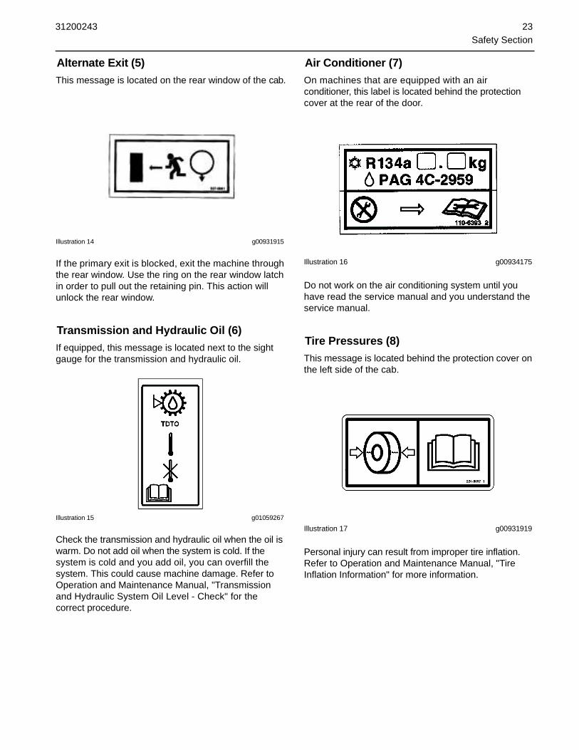
Alternate Exit (5)This message is located on the rear window of the cab.
Illustration 14 g00931915
If the primary exit is blocked, exit the machine through the rear window. Use the ring on the rear window latch in order to pull out the retaining pin. This action will unlock the rear window.
Transmission and Hydraulic Oil (6)If equipped, this message is located next to the sight gauge for the transmission and hydraulic oil.
Illustration 15 g01059267
Check the transmission and hydraulic oil when the oil is warm. Do not add oil when the system is cold. If the system is cold and you add oil, you can overfill the system. This could cause machine damage. Refer to Operation and Maintenance Manual, "Transmission and Hydraulic System Oil Level - Check" for the correct procedure.
Air Conditioner (7)On machines that are equipped with an air conditioner, this label is located behind the protection cover at the rear of the door.
Illustration 16 g00934175
Do not work on the air conditioning system until you have read the service manual and you understand the service manual.
Tire Pressures (8)This message is located behind the protection cover on the left side of the cab.
Illustration 17 g00931919
Personal injury can result from improper tire inflation. Refer to Operation and Maintenance Manual, "Tire Inflation Information" for more information.

24 31200243Safety Section
Machine Security System (9)If equipped, this message is located on the left side of the steering column ahead of the engine start switch.
Illustration 18 g00951606
This machine is equipped with a security system. Read the Operation and Maintenance Manual before you operate the machine.
General Hazard Information
Illustration 19 g00104545
Attach a "Do Not Operate" warning tag or a similar warning tag to the start switch or to the controls before you service the equipment or before you repair the equipment. These warning tags are available from your Caterpillar dealer.
Know the width of your equipment in order to maintain proper clearance when you operate the equipment near fences or near boundary obstacles.
Be aware of high voltage power lines and power cables that are buried. If the machine comes in contact with these hazards, serious injury or death will occur from electrocution.
Illustration 20 g00702020
Wear a hard hat, protective glasses, and other protective equipment, as required.
Do not wear loose clothing or jewelry that can snag on controls or on other parts of the equipment.
Make sure that all protective guards and all covers are secured in place on the equipment.
Keep the equipment free from foreign material. Remove debris, oil, tools, and other items from the deck, from walkways, and from steps.
Secure all loose items such as lunch boxes, tools, and other items that are not a part of the equipment.
Know the appropriate work site hand signals and the personnel that are authorized to give the hand signals. Accept hand signals from one person only.
Do not smoke when you service an air conditioner. Also, do not smoke if refrigerant gas may be present. Inhaling the fumes that are released from a flame that contacts air conditioner refrigerant can cause bodily harm or death. Inhaling gas from air conditioner refrigerant through a lighted cigarette can cause bodily harm or death.
Never put maintenance fluids into glass containers. Drain all liquids into a suitable container.
Obey all local regulations for the disposal of liquids.
Use all cleaning solutions with care. Report all necessary repairs.
Do not allow unauthorized personnel on the equipment.
Unless you are instructed otherwise, perform maintenance with the equipment in the servicing position. Refer to Operation and Maintenance Manual for the procedure for placing the equipment in the servicing position.

31200243 25Safety Section
Pressurized Air and WaterPressurized air and/or water can cause debris and/or hot water to be blown out. This could result in personal injury.
When pressurized air and/or pressurized water is used for cleaning, wear protective clothing, protective shoes, and eye protection. Eye protection includes goggles or a protective face shield.
The maximum air pressure for cleaning purposes must be below 205 kPa (30 psi). The maximum water pressure for cleaning purposes must be below 275 kPa (40 psi).
Trapped PressurePressure can be trapped in a hydraulic system. Releasing trapped pressure can cause sudden machine movement or attachment movement. Use caution if you disconnect hydraulic lines or fittings. High pressure oil that is released can cause a hose to whip. High pressure oil that is released can cause oil to spray. Fluid penetration can cause serious injury and possible death.
Fluid PenetrationPressure can be trapped in the hydraulic circuit long after the engine has been stopped. The pressure can cause hydraulic fluid or items such as pipe plugs to escape rapidly if the pressure is not relieved correctly.
Do not remove any hydraulic components or parts until pressure has been relieved or personal injury may occur. Do not disassemble any hydraulic components or parts until pressure has been relieved or personal injury may occur. Refer to the Service Manual for any procedures that are required to relieve the hydraulic pressure.
Illustration 21 g00687600
Always use a board or cardboard when you check for a leak. Leaking fluid that is under pressure can penetrate body tissue. Fluid penetration can cause serious injury and possible death. A pin hole leak can cause severe injury. If fluid is injected into your skin, you must get
treatment immediately. Seek treatment from a doctor that is familiar with this type of injury.
Containing Fluid SpillageCare must be taken in order to ensure that fluids are contained during performance of inspection, maintenance, testing, adjusting and repair of the equipment. Prepare to collect the fluid with suitable containers before opening any compartment or disassembling any component that contains fluids.
Refer to Special Publication, NENG2500, "Caterpillar Dealer Service Tool Catalog" for the following items:
• Tools that are suitable for collecting fluids andequipment that is suitable for collecting fluids
• Tools that are suitable for containing fluids andequipment that is suitable for containing fluids
Obey all local regulations for the disposal of liquids.
Dispose of Waste Properly
Illustration 23 g00706404
Improperly disposing of waste can threaten the environment. Potentially harmful fluids should be disposed of according to local regulations.
Always use leakproof containers when you drain fluids. Do not pour waste onto the ground, down a drain, or into any source of water.
Crushing Prevention and Cutting PreventionSupport the equipment properly before you perform any work or maintenance beneath that equipment. Do not depend on the hydraulic cylinders to hold up the equipment. Equipment can fall if a control is moved, or if a hydraulic line breaks.
Do not work beneath the cab of the machine unless the cab is properly supported.
Unless you are instructed otherwise, never attempt adjustments while the machine is moving or while the engine is running.

26 31200243Safety Section
Never jump across the starter solenoid terminals in order to start the engine. Unexpected machine movement could result.
Whenever there are equipment control linkages the clearance in the linkage area will change with the movement of the equipment or the machine. Stay clear of areas that may have a sudden change in clearance with machine movement or equipment movement.
If it is necessary to remove guards in order to perform maintenance, always install the guards after the maintenance is performed.
Keep objects away from moving fan blades. The fan blade will throw objects or cut objects.
Do not use a kinked wire cable or a frayed wire cable. Wear gloves when you handle wire cable.
When you strike a retainer pin with force, the retainer pin can fly out. The loose retainer pin can injure personnel. Make sure that the area is clear of people when you strike a retainer pin. To avoid injury to your eyes, wear protective glasses when you strike a retainer pin.
Chips or other debris can fly off an object when you strike the object. Make sure that no one can be injured by flying debris before striking any object.
Burn PreventionDo not touch any part of an operating engine. Allow the engine to cool before any maintenance is performed on the engine. Relieve all pressure in the air system, in the oil system, in the lubrication system, in the fuel system, or in the cooling system before any lines, fittings or related items are disconnected.
CoolantWhen the engine is at operating temperature, the engine coolant is hot. The coolant is also under pressure. The radiator and all lines to the heaters or to the engine contain hot coolant.
Any contact with hot coolant or with steam can cause severe burns. Allow cooling system components to cool before the cooling system is drained.
Check the coolant level only after the engine has been stopped.
Ensure that the filler cap is cool before removing the filler cap. The filler cap must be cool enough to touch with a bare hand. Remove the filler cap slowly in order to relieve pressure.
Cooling system conditioner contains alkali. Alkali can cause personal injury. Do not allow alkali to contact the skin, the eyes, or the mouth.
Stay clear of all rotating and moving parts.
OilsHot oil and hot components can cause personal injury. Do not allow hot oil to contact the skin. Also, do not allow hot components to contact the skin.
Remove the hydraulic tank filler cap only after the engine has been stopped. The filler cap must be cool enough to touch with a bare hand. Follow the standard procedure in this manual in order to remove the hydraulic tank filler cap.
BatteriesElectrolyte is an acid. Electrolyte can cause personal injury. Do not allow electrolyte to contact the skin or the eyes. Always wear protective glasses for servicing batteries. Wash hands after touching the batteries and connectors. Use of gloves is recommended.
Fire Prevention and Explosion Prevention
Illustration 24 g00704000
All fuels, most lubricants, and some coolant mixtures are flammable.
Flammable fluids that are leaking or spilled onto hot surfaces or onto electrical components can cause a fire. Fire may cause personal injury and property damage.
Remove all flammable materials such as fuel, oil, and debris from the machine. Do not allow any flammable materials to accumulate on the machine.
Store fuels and lubricants in properly marked containers away from unauthorized persons. Store oily rags and any flammable materials in protective containers. Do not smoke in areas that are used for storing flammable materials.

31200243 27Safety Section
Do not operate the machine near any flame.
Exhaust shields (if equipped) protect hot exhaust components from oil spray or fuel spray in case of a break in a line, in a hose, or in a seal. Exhaust shields must be installed correctly.
Do not weld on lines or on tanks that contain flammable fluids. Do not flame cut lines or tanks that contain flammable fluid. Clean any such lines or tanks thoroughly with a nonflammable solvent prior to welding or flame cutting.
Check all electrical wires daily. Repair any wires that are loose or frayed before you operate the machine. Clean all electrical connections and tighten all electrical connections.
Dust that is generated from repairing nonmetallic hoods or nonmetallic fenders can be flammable and/or explosive. Repair such components in a well ventilated area away from open flames or sparks.
Inspect all lines and hoses for wear or for deterioration. The hoses must be properly routed. The lines and the hoses must have adequate support and secure clamps. Tighten all connections to the recommended torque. Leaks can cause fires.
Illustration 25 g00704059
Use caution when you are refueling a machine. Remove debris from the top of the tank before refueling. Do not smoke while you are refueling a machine. Do not refuel a machine near open flames or sparks. Always stop the engine before refueling. Fill the fuel tank outdoors.
Illustration 26 g00704135
Gases from a battery can explode. Keep any open flames or sparks away from the top of a battery. Do not smoke in battery charging areas.
Never check the battery charge by placing a metal object across the terminal posts. Use a voltmeter or a hydrometer.
Improper jumper cable connections can cause an explosion that can result in injury. Refer to the Operation Section of this manual for specific instructions.
Do not charge a frozen battery. This may cause an explosion.
Fire ExtinguisherMake sure that a fire extinguisher is available. Be familiar with the operation of the fire extinguisher. Inspect the fire extinguisher and service the fire extinguisher regularly. Obey the recommendations on the instruction plate.
Lines, Tubes and HosesDo not bend high pressure lines. Do not strike high pressure lines. Do not install any lines that are bent or damaged.
Repair any lines that are loose or damaged. Leaks can cause fires. Consult your Caterpillar dealer for repair or for replacement parts.
Check lines, tubes and hoses carefully. Do not use your bare hand to check for leaks. Use a board or cardboard to check for leaks. Tighten all connections to the recommended torque.
Replace the parts if any of the following conditions are present:
• End fittings are damaged or leaking.

28 31200243Safety Section
• Outer coverings are chafed or cut.
• Wires are exposed.
• Outer coverings are ballooning.
• Flexible part of the hoses are kinked.
• Outer covers have embedded armoring.
• End fittings are displaced.
Make sure that all clamps, guards, and heat shields are installed correctly. During machine operation, this will help to prevent vibration, rubbing against other parts, and excessive heat.
Fire Extinguisher LocationMake sure that a fire extinguisher is on the machine. Make sure that you are familiar with the operation of the fire extinguisher. Inspect the fire extinguisher and service the fire extinguisher on a regular basis. Obey the recommendations on the instruction plate.
The recommended location for mounting the fire extinguisher is on the plate for the seat to the right side of the operator.
If the fire extinguisher is mounted on the ROPS, strap the mounting plate to a leg of the ROPS. If the weight of the fire extinguisher is more than 4.5 kg (10 lb), mount the fire extinguisher as low as possible on one leg. Do not mount the fire extinguisher on the upper one-third area of the leg.
Note: Do not weld the ROPS in order to install the fire extinguisher. Also, do not drill holes in the ROPS in order to mount the fire extinguisher on the ROPS.
Tire InformationExplosions of air inflated tires have resulted from heat-induced gas combustion inside the tires. Explosions can be caused by heat that is generated by welding, by heating rim components, by external fire, or by excessive use of brakes.
A tire explosion is much more violent than a blowout. The explosion can propel the tire, the rim components, and the axle components as far as 500 m (1500 ft) or more from the machine. Both the force of the explosion and the flying debris can cause property damage, personal injury, or death.
Illustration 27 g00847810(A) At least 15 m (50 ft)
(B) At least 500 m (1500 ft)
Do not approach a warm tire. Maintain a minimum distance, as shown. Stay outside the shaded area in Illustration 27.
To avoid overinflation, proper training in the usage of the equipment are necessary. A tire blowout or a rim failure can result from improper equipment or from misused equipment.
When you inflate a tire, stand behind the tread and use a self-attaching chuck.
Servicing tires and rims can be dangerous. Only trained personnel that use proper tools and proper procedures should perform this maintenance. If correct procedures are not used for servicing tires and rims, the assemblies could burst with explosive force. This explosive force can cause serious personal injury or death. Carefully obey the specific instructions from your tire dealer.
Electrical Storm Injury PreventionWhen lightning is striking in the vicinity of the machine, the operator should never attempt the following procedures:
• Mount the machine.
• Dismount the machine.
If you are in the operator's station during an electrical storm, stay in the operator's station. If you are on the ground during an electrical storm, stay away from the vicinity of the machine.

31200243 29Safety Section
Before Starting EngineOperators must have had the proper training and operators must be capable in all aspects of machine operation. To comply with some local requirements, an operator must attain an operators license or a certificate.
You must be familiar with your machine in order to understand the machine's capabilities. Also, before you operate your machine you must become familiar with the job site. If necessary, walk around the area and take note of the following items.
• Check the area for clearance. Check for bothvertical clearance and for horizontal clearance.
• Check for the presence of overhead obstructions.
• Check for electrical power lines. Keep the machineand the attachments away from electrical powerlines at least 8 m (25 ft).
• Check for steam lines. Check for compressed airlines.
• Check for changes in the stability of the surfaceof the job site. Check trenches that have beenbackfilled. Check deteriorated roofs of basementsand of tunnels.
• Check sewers and service ducts.
When a load is picked up or when the boom is extended, ensure that the surface on the job site offers even resistance for the tires. Also, when a load is picked up or when the boom is extended, ensure that the surface on the job site offers even penetration for the stabilizers.
Make sure that the load charts and the instruction plates are in place and that the load charts and the instructions can be read. Do not operate the machine until you understand the correct method of using the load charts.
On machines that are equipped with a cab, secure the door in the shut position. Secure the windows in either the open position or in the shut position. Ensure that all windows are clean for the best visibility.
Inspect the condition of the seat belt and of the mounting hardware. Replace any parts that are worn or damaged. Regardless of appearance, replace the seat belt after three years of use. Do not use a seat belt extension on a retractable seat belt.
Make sure that all protective guards and covers are secured on the machine.
Adjust the seat so that full pedal travel can be achieved with the operator's back against the back of the seat.
Make sure that the machine is equipped with a lighting system that is adequate for the job conditions. Make sure that all of the machine lights are working properly.
Make sure that the machine horn, the backup alarm and all other warning devices are working properly.
Clear all obstacles from the path of the machine.
Before you attempt to start the engine and before you move the machine, ensure that no one is underneath the machine, around the machine, or on the machine. Make sure that the area is free of personnel. Fasten the seat belt.
Engine Starting
Illustration 28 g00100846
Before you service the machine or before you repair the machine, attach a "DO NOT OPERATE" warning tag or a similar warning tag to the engine start switch or to the controls. This warning tag is available from your Caterpillar dealer.
If a warning tag is attached to the engine start switch or to the machine controls, do not start the engine. Also, do not move any machine controls.
Ensure that the transmission control is in the NEUTRAL position (N). The engine will not start unless the transmission control is in the NEUTRAL position.
Ensure that the parking brake is engaged.
Diesel engine exhaust contains products of combustion which can be harmful to your health. Always run the engine in a well ventilated area. If you are in an enclosed area, vent the exhaust to the outside.
Start the engine only when you are properly seated in the operator's compartment. Do not short across the battery terminals and do not short across the batteries. A short could cause a bypass of the engine neutral start system and this could cause the machine to move if the machine was left in gear.
30 31200243Safety Section
Before OperationClear all personnel from the machine and from the area.
Clear all obstacles from the path of the machine. Beware of hazards such as wires, ditches, etc.
Make sure that all windows are clean. Secure the doors in the open position or in the shut position. Secure the windows in the open position or in the shut position.
Make sure that all mirrors (if equipped) are clean. For the best vision of the area which is close to the machine, adjust the mirrors. All mirrors should be adjusted for optimal visibility while the operator is seated in the cab.
Make sure that the machine horn, the backup alarm (if equipped), and all other warning devices are working properly.
Fasten the seat belt securely.
Make sure that the load charts and the instruction plates are in place and that the load charts and the instructions can be read.
Operation
Machine Operating Temperature RangeThe standard machine configuration is intended for use within an ambient temperature range of -40 °C (-40 °F) to 50 °C (122 °F). Special configurations for different ambient temperatures may be available. Consult your Caterpillar dealer for additional information on special configurations of your machine.
Machine OperationCheck for proper operation of the steering controls and of the braking controls for the machine while the machine is moving slowly in an open area. Check the steering controls and the braking controls while the boom is retracted fully and the work tool is just clear of the ground. With the machine in a stationary position, check for the proper operation of the other controls for the machine. Unless the machine frame is level, do not raise the boom. The boom should only be extended if the machine frame is level. Extend the boom and retract the boom several times in order to warm the hydraulic oil.
TravelOnly operate the machine while you are in a seat. The seat belt must be fastened while you operate the machine. Only operate the controls while the engine is running.
When you travel on the roadways, operate the machine in two-wheel steer mode only.
Before you maneuver the machine, make sure that no personnel are between the machine and the work tools. Use caution when you change direction of travel. Use caution when you operate the boom. Use caution when you are picking up loads or when you are setting down loads. Travel in the direction of the best visibility. Travel with the boom fully retracted. Also, travel with the boom lowered as far as possible. Maintain adequate ground clearance for conditions. Never travel if a load is raised beyond the travel position. Be careful to avoid any ground condition which could cause the machine to tip. Avoid any conditions that can lead to tipping of the machine. The machine can tip when you work on the following obstacles: banks, hills, and slopes. If the machine is equipped with stabilizers the stabilizers must be fully raised before you move the machine.
Lifting CapacitiesMaintain control of the machine. Do not overload the machine beyond the machine capacity. Ensure that the correct load chart is referenced. Loads must be within the weight limit of the machine and loads must be within the load center limit for the machine. Lifting capacity decreases as the load is moved further from the machine.
Note: If an 180-6137 Coupler Adapter Gp for a work tool is installed on the quick coupler, reduce the load carrying capacity of the machine by 200 kg (440 lb) for all work tools and with the boom in any position. Refer to Operation and Maintenance Manual, "Lifting Capacities" for additional information.
Ensure that the tires are serviceable and that the tires are inflated to the correct pressure.
On machines that are equipped with a frame leveling switch, always level the frame before you raise the boom or before you lower the stabilizers. Never operate the frame leveling switch when the boom is raised or when the stabilizers are lowered. Check that the frame is level after you lower the stabilizers. If necessary, adjust the level of the frame. Use the stabilizers in order to make the adjustment. Do not adjust the position of the stabilizers when the boom is raised. If the frame is not level, do not raise the boom.
Before you transport a load or before you elevate a load, the load must be adequately secured on the forks or on the work tool. Any loads such as pipe, scaffolding, lumber and beams must be adequately secured.
Use lifting slings that are approved and use lifting slings that are load tested. Also, all wire ropes or chains must be properly maintained. The wire ropes and chains must meet local regulations. You must know the load carrying capacity of these devices and you must know the correct use of these devices.

31200243 31Safety Section
Work Tools
Use of non approved work tools on Telehandlermachines could result in injury or death.
Before installing a work tool on this machine, ensurethat it is approved by Caterpillar and that a Caterpillarload chart covering its use is installed in the machine'scab.
NOTICE
When certain work tools are fitted, the work tools can contact the front tires or the front fenders. This situation can occur when the boom is retracted and the work tool is rotated fully forward. Always check for interference when first operating a new work tool.
Before you use a work tool, ensure that the work tool is approved by Caterpillar. Also, ensure that the machine has a Caterpillar load chart. Consult your Caterpillar dealer for information on the proper application and the proper use of a specific work tool.
Engine StoppingDo not stop the engine immediately after the machine has been operated under load. This can cause overheating and accelerated wear of engine components.
After the machine is parked and the parking brake is engaged, allow the engine to run for five minutes before shutdown. This allows hot areas of the engine to cool gradually.
For more information, refer to the following topics in the Operation Section of the Operation and Maintenance Manual:
• "Stopping the Engine"
• "Stopping the Engine if an Electrical MalfunctionOccurs"
Work Tools
Use of non approved work tools on Telehandlermachines could result in injury or death.
Before installing a work tool on this machine, ensurethat it is approved by Caterpillar and that a Caterpillarload chart covering its use is installed in the machine'scab.
If you are in doubt about the compatibility of a particular work tool with your machine, consult your Caterpillar dealer.
Make sure that all necessary guarding is in place on the host machine and on the work tool.
Keep all windows and doors closed on the host machine. Always wear protective glasses. Always wear the protective equipment that is recommended in the work tool's operation manual. Wear any other protective equipment that is required for the operating environment.
To prevent personnel from being struck by flying objects, ensure that all personnel are out of the work area.
While you are performing any maintenance, any testing, or any adjustments to the work tool stay clear of the following areas: cutting edges, pinching surfaces, and crushing surfaces.
ParkingPark the machine on a level surface. If you must park on a grade, chock the machine's wheels. The boom must be fully retracted. Fully retract the boom and lower the boom until the work tool is on the ground.
Apply the service brakes in order to stop the machine. Move the transmission control to the NEUTRAL position. Move the accelerator control to the LOW IDLE position. Engage the parking brake.
Lower all equipment to the ground. Activate any control locks.
Stop the engine.
Turn the engine start switch to the OFF position and remove the engine start switch key.
Turn the battery disconnect switch (if equipped) to the OFF position. Remove the disconnect switch key if you do not operate the machine for an extended period of time. This will prevent drainage of the battery. A battery short circuit, any current draw from certain components, and vandalism can cause drainage of the battery.

32 31200243Safety Section
Equipment Lowering with Loss of Hydraulic PowerBefore you lower any equipment with loss of hydraulic power, clear the area around the equipment of all personnel. The procedure to lower the equipment will vary with the type of equipment that is being lowered. Most systems use high pressure air or fluid to control the equipment. The procedure may release the pressure in a high pressure system in order to lower the equipment. Wear appropriate protective equipment. Follow the established procedure for lowering equipment without hydraulic power in the Operation Section of the Operation and Maintenance Manual.
Sound Information and Vibration Information
Sound LevelThe operator sound pressure level that is measured according to the test procedure that is specified in "EN 12053:2001" is 80 dB(A) for an enclosed cab. The cab was properly installed and maintained. The test was conducted with the doors and the windows closed.
Hearing protection may be needed when the machine is operated with an open operator station for extended periods or in a noisy environment. Hearing protection may be needed when the machine is operated with a cab that is not properly maintained or when the doors and windows are open for extended periods or in a noisy environment.
Vibration LevelThe hands and arms are exposed to a weighted root
mean square acceleration that is less than 2.5 m/sec2
(8.20 ft/sec2).
The whole body is exposed to a weighted root mean
square acceleration that is less than 0.5000 m/s2 (1.70
ft/sec2).
The measurements are obtained on a standard machine. The measurements are obtained by using the procedures that are in the following standards:
• "ISO 2631-1:1997"
• "ISO 5349-1:2001"
• "SAEJ1166"
Operator StationAny modifications to the inside of the operator station should not project into the operator space. The addition of a radio, fire extinguisher, and other equipment must be installed so that the defined operator space is maintained. Any item that is brought into the cab should not project into the defined operator space. A lunch box or other loose items must be secured. Objects must not pose an impact hazard in rough terrain or in the event of a rollover.
Guards (Operator Protection)There are different types of guards that are used to protect the operator. The machine and the machine application determines the type of guard that should be used.
A daily inspection of the guards is required in order to check for structures that are bent, cracked or loose. Never operate a machine with a damaged structure.
The operator becomes exposed to a hazardous situation if the machine is used improperly or if poor operating techniques are used. This situation can occur even though a machine is equipped with an appropriate protective guard. Follow the established operating procedures that are recommended for your machine.

31200243 33Safety Section
Rollover Protective Structure (ROPS), Falling Object Protective Structure (FOPS)The ROPS/FOPS Structure (if equipped) on your machine is specifically designed, tested and certified for that machine. Excavators are not equipped with ROPS structures. Any alteration or any modification to the ROPS/FOPS Structure could weaken the structure. This places the operator into an unprotected environment. Modifications or attachments that cause the machine to exceed the weight that is stamped on the certification plate also place the operator into an unprotected environment. Excessive weight may inhibit the brake performance, the steering performance and the ROPS. The protection that is offered by the ROPS/FOPS Structure will be impaired if the ROPS/FOPS Structure has structural damage. Damage to the structure can be caused by an overturn, a falling object, a collision, etc.
Do not mount items (fire extinguishers, first aid kits, work lights, etc) by welding brackets to the ROPS/FOPS Structure or by drilling holes in the ROPS/FOPS Structure. Welding brackets or drilling holes in the ROPS/FOPS Structures can weaken the structures. Consult your Caterpillar dealer for mounting guidelines.
Other Guards (If Equipped)Protection from flying objects and/or falling objects is required for special applications. Logging applications and demolition applications are two examples that require special protection.
A front guard needs to be installed when a work tool that creates flying objects is used. Mesh front guards that are approved by Caterpillar or polycarbonate front guards that are approved by Caterpillar are available for machines with a cab or an open canopy. On machines that are equipped with cabs, the windshield should also be closed. Safety glasses are recommended when flying hazards exist for machines with cabs and machines with open canopies.
If the work material extends above the cab, top guards and front guards should be used. Typical examples of this type of application are listed below:
• Demolition applications
• Rock quarries
• Forestry products
Additional guards may be required for specific applications or work tools. The Operation and Maintenance Manual for your machine or your work tool will provide specific requirements for the guards. Consult your Caterpillar dealer for additional information.

34 31200243Safety Section

31200243 35Product Information Section
Product Information Section
General Information
Lifting CapacitiesWhen a machine is operated on tires, the machine capacities are different from a machine that is operated on stabilizers. Also, the machine capacities for each type of attachment are different.
Machine instability can result in injury or death. Toensure stability during operation the followingconditions must be observed:
Tires must be correctly inflated and have the correctamount of ballast (if equipped).
The machine frame must be level.
The frame level switch must never be operated whenthe boom is raised.
The frame level switch must never be operated whenstabilizers are lowered.
Stabilizer switches must never be operated when theboom is raised.
The correct load chart for the machine as equippedmust be referenced and the weights and load centersspecified must never be exceeded.
The machine must never be moved when the boom israised.
Illustration 29 g00955167
The load charts are located on the dash panel at the right side of the instrument cluster. Ensure that the correct load chart is used. The chart is intended for the type of attachment that is represented by a symbol at the top of the chart. Symbols are also shown for operation on tires or on stabilizers. The load charts may be in metric units (meters and kilograms) or conventional units (feet and pounds).
When the machine is operated on tires, the weight of the intended load determines the maximum height above ground. The weight of the intended load also determines the maximum distance that is between the load center of gravity and the front wheels.
When the machine is operated with lowered stabilizers, the weight of the intended load determines the maximum height above ground. The weight of the intended load also determines the maximum distance that is between the load center of gravity and the stabilizer pads.
The machine boom has two scales which must be used for reference with the load chart in order to assess the lift operation. The boom extension reference scale gives an indication of the boom length. The letters "B", "C" and "D" correspond to the same letters on the load chart.
Illustration 30 g00955168
Boom angle reference scale (1) gives an indication of the angle of the boom.
Follow the instructions below in order to assess the intended load:
1. Carefully position the machine. The machine should be as close as possible to the intended load. For more information on operating the machine, refer to the appropriate topic in the Operation Section of the Operation and Maintenance Manual.
2. In order to move the attachment into position for the operation, raise the boom and extend the boom, as required. Do not make the liftoperation.
3. Look at the boom extension reference scale and the boom angle reference scale and note the readings. Refer to the load chart and use these two values in order to locate the equivalent load zone.
4. If the intended load is equal to the value in theequivalent load zone the lift operation can beattempted with caution. Also, if the intended loadis less than the value in the equivalent load zonethe lift operation can be attempted with caution.

36 31200243Product Information Section
5. If the intended load is heavier than the value in the equivalent load zone the lift operation cannot be made.
Examples of Estimating the Lift Operation from the Load ChartNote: The examples that follow are only for illustrative purposes. This chart does not relate to any particular machine. For lift operation, you should consult the load charts that are mounted in the operator station. The units on the load charts can be either kilograms or pounds.
Each load chart has two parts:
• The chart shows regions which indicate if certaincapacities can be lifted.
• The derate table shows the loads that can be liftedin the regions that are identified in the chart. Multiplework tools are included and the operator must selectthe work tool which is being used. The examples usethe standard fork carriage.
Example 1• The weight of the intended load is 1000 units.
• The boom angle reference is 55 degrees.
• The boom extension reference scale is at "D".
With reference to the load chart, "X" is the point of intersection for the values of the boom angle reference and the boom extension reference. This point of intersection is located in the load zone that is marked "G". With reference to the derate table, the load zone capacity of the work tool is 2000 units. The intended load of 1000 units is less than the value in the load zone so the load chart indicates that the load is within the capacity of the machine.
Example 2• The weight of the intended load is 3000 units.
• The boom angle reference is 40 degrees.
• The boom extension reference scale is at "B".
With reference to the load chart, "Y" is the point of intersection for the values of the boom angle reference and the boom extension reference. This point of intersection is located in the load zone that is marked "E". With reference to the derate table, the load zone capacity of the work tool is 3000 units. The intended load of 3000 units is the same value as the value in the load zone so the load chart indicates that the load is at the maximum capacity of the machine.
Example 3• The weight of the intended load is 600 units.
• The boom angle reference is 22 degrees.
• The boom extension reference scale isapproximately 66 percent between "D" and fullextension.
With reference to the load chart, "Z" is the point of intersection for the values of the boom angle reference and the boom extension reference. This point of intersection is located in the load zone that is marked "K". With reference to the derate table, the load zone capacity of the work tool is 400 units. The intended load of 600 units is greater than the value in the load zone so the load chart indicates that the load is beyond the capacity of the machine. The lift operation must not be attempted.
If the load chart indicates that the lift operation is within the capacity of the machine, attempt to make the operation but proceed with care. Remember that the load may weigh more than the estimate for the load. The load chart is for estimating the lift operation only.

31200243 37Product Information Section
Illustration 31 g01013841 Typical Load Chart
Specifications
Illustration 34 g00855391
Illustration 35 g00855455Rear View
Specifications are shown for basic machines without a work tool on the quick coupler.
Table 7
TH360B Machine
Overall Height (A) 2590 mm (8 ft 6 inch)
Overall Length (B) 6385 mm (20 ft 11 inch)
Overall Width (C) 2440 mm (8 ft 0 inch)
Wheel Base 3200 mm (10 ft 6 inch)
Ground Clearance 500 mm (1 ft 7.7 inch)
Approximate Weight 9720 kg (21400 lb)

38 31200243Product Information Section
Intended UseThis vehicle is classified either as:
• A self-propelled variable reach truck (Telehandler) asdefined in "ISO 3691-2" and "EN 1459:1998"
• An agricultural tractor when meeting the requirements of European Union Directive 74/150/EEC
This vehicle is all wheel drive and has all wheel steer ability. This vehicle has a rigid chassis with a variable reach boom mounted centrally on to which a range of Caterpillar approved attachments may be attached.
As a machine, the vehicle has a primary use as a material handler to pickup and place materials. As an agricultural tractor, the vehicle has a primary use for towing.
Application/Configuration RestrictionsMaximum approved operating weight -
TH360B 12100 kg (26620 lb)
Maximum drawbar towing force - Refer to Operation and Maintenance Manual, "Towing the Machine" for more information.
Maximum drawbar vertical load - Refer to Operation and Maintenance Manual, "Towing the Machine" for more information.
Maximum fore and aft slope on this machine in a static condition to maintain proper lubrication -
• For machines equipped with a 92 kW engine, 57.7percent grade or 30 degrees
• For machines equipped with a 74.5 kW engine, 44.5percent grade or 24 degrees
Identification Information
Plate Locations and Film Locations
Illustration 36 g00937576
An information plate is installed on these machines. On machines that are delivered into the European Union, the CE mark and the PIN are stamped onto the plate. On machines that are delivered to countries outside the European Union, the PIN is stamped onto the plate. This plate is positioned on the left side of the main frame.
The PIN is used to identify a powered machine that is designed for an operator to ride. The PIN plate is located at the left side of the main frame.
The PIN plate shows the PIN and the number for the arrangement of the machine.
Several pieces of information are stamped onto the PIN plate. For quick reference, record this information in the spaces that are provided below.
• Model____________________________________
• PIN______________________________________
• Engine serial number________________________
• Transmission serial number___________________
������ ���
����������
���������������������������������������������
������
�������������������
���
�������!�����"���#$
%���������!���
&�����������!���"�'(
�����)�*�����+��!*�
,�����#�������
-����#�������
��#�������������
��#�������������������#$�.��!*�
�
�����������������������������!�/�����0�0 ��������������&����0��������12"�0���+����������3141���������*�����5�0��!���
'!
'!
'!
'!
'!
'!
������3244�
�������