operation and maintenance information -...
TRANSCRIPT
04614020
Edition 5February 2011
Save These Instructions
Air Motor
MRV009, MRV015, MRV040, MRV050
Series Reversible
Operation and
Maintenance Information
EN Operation and Maintenance Information
ES Operación y Mantenimiento de InformaciónFR L’utilisation et la Maintenance Informations
EN-2 04614020_ed5
EN
WARNING
General Product Safety Information
Important Safety Information enclosed.
Read and understand this manual before operating this tool.
It is your responsibility to make this safety information available to others that will operate this tool.
WARNING
Failure to observe the following warnings could result in injury.
•••
Placing the Motor in Service
Always install, operate, inspect and maintain this product in accordance with all applicable standards and regulations (local, state, country, federal, etc.).Always use clean, dry air at 90 psig (6.2 bar/620 kPa) maximum air pressure at the inlet. Higher pressure may result in hazardous situations including excessive speed, rupture, or incorrect output torque or force.Ensure an accessible emergency shut off valve has been installed in the air supply line, and make others aware of its location.Do not use damaged, frayed or deteriorated air hoses and fi ttings.Always turn off the air supply and disconnect the air supply hose
•
•
•
••
before installing, removing or performing any maintenance on this motor.Do not lubricate with fl ammable or volatile liquids such as kerosene, diesel or jet fuel. Use only recommended lubricants.Keep work area clean, uncluttered, ventilated and illuminated.Do not remove any labels. Replace any damaged label.
•
••
Using the Motor
Always wear eye protection when operating or performing maintenance on this motor.Always wear hearing protection when operating this motor.Always use Personal Protective Equipment appropriate to the motor used. This may include dust mask or other breathing apparatus, safety glasses, ear plugs, gloves, apron, safety shoes, hard hat and other equipment.Keep others a safe distance from your work area, or ensure they use appropriate Personal Protective Equipment.This motor is not insulated against electric shock.Keep hands, loose clothing, long hair and jewelry away from motor.
•
••
•
••
Motor and/or accessories may briefl y continue their motion after throttle is released.Do not operate when tired, or under the infl uence of medication, drugs, or alcohol.Never use a damaged or malfunctioning motor or accessory.Do not modify the motor, safety devices, or accessories.Do not use this motor for purposes other than those recommended.Use accessories recommended for Ingersoll Rand Products.
•
•
•••
•
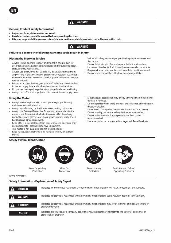
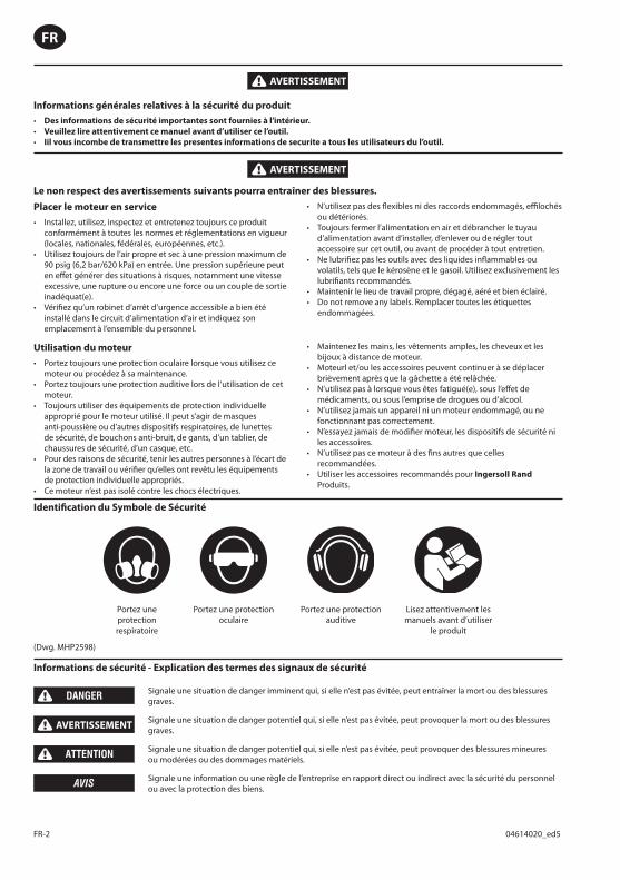
Safety Symbol Identifi cation
Wear Respiratory Protection
Wear Eye Protection
Wear Hearing Protection
Read Manuals Before Operating Products
(Dwg. MHP2598)
Safety Information - Explanation of Safety Signal
DANGER Indicates an imminently hazardous situation which, if not avoided, will result in death or serious injury.
WARNING Indicates a potentially hazardous situation which, if not avoided, could result in death or serious injury.
CAUTION Indicates a potentially hazardous situation which, if not avoided, may result in minor or moderate injury or property damage.
NOTICE Indicates information or a company policy that relates directly or indirectly to the safety of personnel or protection of property.
04614020_ed5 EN-3
EN
Model Designation Breakout
MRV XXX A
009
015
040
050
MRV SeriesAir Motors
A = Round Shaft With Square Key
B = Round Shaft with Woodruff key #3
C = Round Shaft with Flat on Shaft
B5D71 = Round Shaft (14mm) with Square Key*
B5D80 = Round Shaft (19mm) with Square Key**B5D90 = Round Shaft (24mm) with Square Key***
MRV
Shaft/InterfaceSeries
* Available on MRV009, MRV015, MRV040 only
** Available on MRV040 only
*** Available on MRV050 only
IR# 10
Lubrication
Ingersoll Rand suggests using an air line lubricator with these motors. We recommend a 1/2” Filter-Regulator-Lubricator (FRL) for optimum motor performance and life.
Ingersoll Rand Series vanes are made of a special material that does not require lubrication. While we suggest lube for optimum service life, our vanes have been shown to last substantially longer than standard laminate versions. This makes Ingersoll Rand motors a good choice for Food Grade or Clean Room environments where oil is not permitted.
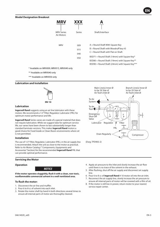
Installation
The use of 1/2” Filter, Regulator, Lubricator (FRL), in the air supply line is recommended. Attach the unit as close to the motor as practical.Refer to Air Motor Catalog (“ Components, Equipments and Accessories” Section) for the recommended Ingersoll Rand FRL that can provide optimal performance.
FLR
Main Line(s) Inner Øto be 3X Size ofAir Tool’s Inlet Ø
To AirSystem
To AirTool
Lubricator
EmergencyShut-OffValve
Regulator Filter
Compressor
FRL
Drain Regularly
Branch Line(s) Inner Øto be 2X Size ofAir Tool’s Inlet Ø
(Dwg. TPD905-2)
Servicing the Motor
Operation
NOTICE
If the motor operates sluggishly, fl ush it with a clean, non-toxic,
nonfl ammable commercial solvent in a well ventilated area.
To fl ush the motor:
Disconnect the air line and muffl er.Pour 6 to 8 cc of solvent into each inlet.Rotate the motor shaft by hand in both directions several times to ensure all internal parts of motor are thoroughly cleaned.
1.2.3.
Apply air pressure to the inlet and slowly increase the air fl ow until there is no trace of the solvent in the exhaust.After fl ushing, shut off the air supply and disconnect air supply line.Pour 6 to 8 cc of Ingersoll Rand # 10 motor oil into the air inlet.Reconnect the air supply line, slowly increase the air pressure to ensure all internal parts of motor will be covered with a fi lm of oil.If the motor is still low in power, return motor to your nearest service repair center.
4.
5.
6.7.
8.
Lubrication and Installation

ES-1 04614020_ed5
ES
ADVERTENCIA
Información general sobre seguridad del producto
Importante información de seguridad adjunta.
Lea este manual y asegúrese de comprenderlo bien antes de utilizar este producto.
Es su responsabilidad poner esta información de seguridad a disposición de quienes vayan a utilizar el producto.
ADVERTENCIA
El hecho de hacer caso omiso a las advertencias siguientes podría ocasionar lesiones.
La colocación del motor en servicio
Instale, utilice, inspeccione y mantenga siempre este producto de acuerdo con todas las regulaciones y normas aplicables (locales, estatales, nacionales, federales, etc.).Use siempre aire limpio y seco a una presión máxima de 60 psig (4,2 bares/413 kPa) en la entrada de aire del dispositivo. Una presión superior puede redundar en situaciones peligrosas, entre ellas una velocidad excesiva, rotura, o un par o una fuerza de salida incorrectos.Asegúrese de que la válvula de cierre de emergencia accesible haya sido instalada en la línea de alimentación de aire y ponga su ubicación en conocimiento de los demás.No utilice mangueras de aire y accesorios dañados, desgastados ni deteriorados.Corte siempre el suministro de aire y desconecte la manguera de suministro de aire antes de instalar, desmontar o ajustar cualquier accesorio de esta herramienta, o antes de realizar cualquier operación de mantenimiento de la misma.No lubrique las herramientas con líquidos infl amables o volátiles tales como queroseno, gasoil o combustible para motores a reacción. Use sólo los lubricantes recomendados.Mantenga la zona de trabajo limpia, despejada, ventilada e iluminada.No retire ninguna etiqueta. Sustituya cualquier etiqueta dañada.
Usando el motor
Use siempre protección ocular cuando utilice o realice operaciones de mantenimiento en este motor.Use siempre protección para los oídos cuando maneje esta motor.Utilice siempre el equipo de protección individual que corresponda a la corresponda a la de motor usado. Esto puede incluir una mascarilla contra el polvo u otro aparato de respiración, gafas de seguridad, tapones para los oídos, guantes, delantal, zapatos de seguridad, casco y otros artículos.Mantenga a los demás a una distancia segura de la zona de trabajo o asegúrese de que utilizan el correspondiente equipo de protección individual.Este motor no está aislado contra descargas eléctricas.Mantenga las manos, la ropa suelta, el cabello largo y las alhajas apartados del extremo de trabajo de la motor.El movimiento de la Motor y / o accesorios puede prolongarse brevemente después de soltarse el mando.No utilice este producto cuando esté cansado o bajo la infl uencia de medicamentos, drogas o alcohol.No utilice nunca un motor o un accesorio dañado o que no funcione correctamente.No modifi que la motor, los dispositivos de seguridad ni los accesorios.No utilice esta motor para otros fi nes que no sean los recomendados.Utilice accesorios recomendados por Ingersoll Rand Productos.Identifi cación de los símbolos de seguridad
Utilice protección respiratoria
Utilice protección ocular Utilice protección acústica
Lea los manuales antes de utilizar el producto
(Dwg. MHP2598)
Información de seguridad: Explicación de los mensajes de las señales de seguridad
PELIGRO Indica una situación de peligro inminente que, de no evitarse, resultaría en lesiones graves o muerte.
ADVERTENCIA Indica una situación potencialmente peligrosa que, de no evitarse, podría resultar en lesiones graves o muerte.
CUIDADO Indica una situación potencialmente peligrosa que, de no evitarse, podría producir lesiones de leves a moderadas o daños en la propiedad.
AVISO Indica información o una política de la empresa directa o indirectamente relacionada con la seguridad del personal o la protección de la propiedad.
•••
•
•
•
••
•
••
•••
•
••••••••

04614020_ed5 ES-2
ES
Designación de modelo
MRV XXX A
009
015
040
050
MRV SeriesMotor de Aire
A = Ronda del eje con la llave cuadradaB = Ronda Eje con Woodruff tecla # 3
C = Ronda de eje con plano en el eje
B5D71 = Ronda del eje (14 mm) con la llave cuadrada *
B5D80 = Ronda del eje (19 mm) con la llave cuadrada **B5D90 = Ronda del eje (24 mm) con la llave cuadrada ***
MRV
Eje/Interfaz Series
* Disponible en MRV009, MRV015, sólo MRV040
** Disponible en MRV040 sólo
*** Disponible en MRV050 sólo
IR# 10
Lubricación
Ingersoll Rand sugiere el uso de un lubricante de aire comprimido con estos motores. Se recomienda de 1 / 2 “Filtro-Regulador-Lubricador (FRL) para un rendimiento óptimo del motor y la vida.
Ingersoll Rand paletas de la serie están hechas de un material especial que no requiere lubricación. Aunque le sugerimos lubricante para una vida útil óptima, nuestro paletas Se ha demostrado que por última considerablemente más que las versiones laminado. Esto hace que Ingersoll Rand motores una buena opción para la alimentación de grado o limpieza en los entornos de la habitación donde el petróleo no está permitido.
Instalación
El uso de 1 / 2 “Filtro, regulador, lubricador (FRL), en la línea de suministro de aire se recomienda. Coloque la unidad lo más cerca del motor como sea posible. Consulte el Catálogo de aire del motor (“Componentes, Equipos y Accesorios” Sección) recomienda para la FRL Ingersoll Rand que puede proporcionar un rendimiento óptimo.
FLR
Línea (s) Ø interior que se3X Tamaño de la entrada de la herramienta Ø Aérea
Para Sistemade aire
Para Herramienta
de aire
Válvula de corte de emergencia
Lubricante Regulador Filtro
Compresor
FRL
Vacíe regularmente
Ramal (s) Ø interior que se 2X Tamaño de la entrada de la herramienta Ø Aérea
(Dwg. TPD905-2)
Funcionamiento
AVISO
Si el motor funciona lentamente, tirar de la cadena con un paño
limpio, no tóxico, no infl amable solvente comercial en un área
bien ventilada.
Para lavar el motor:
Desconecte la línea de aire y silenciador.Vierta 6 a 8 cc de disolvente en cada orifi cio de salida.Gire el eje del motor con la mano en ambos sentidos varias veces para asegurar que todas las partes internas del motor se limpian a fondo.Aplique presión de aire a la entrada y poco a poco aumentar el fl ujo de aire hasta que no hay rastro del solvente en el escape.
1.2.3.
4.
Después de lavar, cortar el suministro de aire y desconectar la línea de suministro de aire.Vierta 6 a 8 cc de Ingersoll Rand aceite de motor # 10 en la entrada de aire.Vuelva a conectar la línea de suministro de aire, aumente lentamente la presión del aire para asegurar que todas las partes internas del motor se cubre con una capa de aceite.Si el motor sigue siendo baja en el poder, el motor regresar a su centro de servicio de reparación.
5.
6.
7.
8.
Mantenimiento del Motor
Lubricación & Instalación
FR-2 04614020_ed5
FR
AVERTISSEMENT
Informations générales relatives à la sécurité du produit
Des informations de sécurité importantes sont fournies à l’intérieur.
Veuillez lire attentivement ce manuel avant d’utiliser ce l’outil.
Iil vous incombe de transmettre les presentes informations de securite a tous les utilisateurs du l’outil.
AVERTISSEMENT
Le non respect des avertissements suivants pourra entraîner des blessures.
•••
Placer le moteur en service
Installez, utilisez, inspectez et entretenez toujours ce produit conformément à toutes les normes et réglementations en vigueur (locales, nationales, fédérales, européennes, etc.).Utilisez toujours de l’air propre et sec à une pression maximum de 90 psig (6,2 bar/620 kPa) en entrée. Une pression supérieure peut en eff et générer des situations à risques, notamment une vitesse excessive, une rupture ou encore une force ou un couple de sortie inadéquat(e).Vérifi ez qu’un robinet d’arrêt d’urgence accessible a bien été installé dans le circuit d’alimentation d’air et indiquez son emplacement à l’ensemble du personnel.
•
•
•
N’utilisez pas des fl exibles ni des raccords endommagés, effi lochés ou détériorés.Toujours fermer l’alimentation en air et débrancher le tuyau d’alimentation avant d’installer, d’enlever ou de régler tout accessoire sur cet outil, ou avant de procéder à tout entretien.Ne lubrifi ez pas les outils avec des liquides infl ammables ou volatils, tels que le kérosène et le gasoil. Utilisez exclusivement les lubrifi ants recommandés.Maintenir le lieu de travail propre, dégagé, aéré et bien éclairé.Do not remove any labels. Remplacer toutes les étiquettes endommagées.
•
•
•
••
Utilisation du moteur
Portez toujours une protection oculaire lorsque vous utilisez ce moteur ou procédez à sa maintenance.Portez toujours une protection auditive lors de l’utilisation de cet moteur.Toujours utiliser des équipements de protection individuelle approprié pour le moteur utilisé. Il peut s’agir de masques anti-poussière ou d’autres dispositifs respiratoires, de lunettes de sécurité, de bouchons anti-bruit, de gants, d’un tablier, de chaussures de sécurité, d’un casque, etc.Pour des raisons de sécurité, tenir les autres personnes à l’écart de la zone de travail ou vérifi er qu’elles ont revêtu les équipements de protection individuelle appropriés.Ce moteur n’est pas isolé contre les chocs électriques.
•
•
•
•
•
Maintenez les mains, les vêtements amples, les cheveux et les bijoux à distance de moteur.Moteurl et/ou les accessoires peuvent continuer à se déplacer brièvement après que la gâchette a été relâchée.N’utilisez pas à lorsque vous êtes fatigué(e), sous l’eff et de médicaments, ou sous l’emprise de drogues ou d’alcool.N’utilisez jamais un appareil ni un moteur endommagé, ou ne fonctionnant pas correctement.N’essayez jamais de modifi er moteur, les dispositifs de sécurité ni les accessoires.N’utilisez pas ce moteur à des fi ns autres que celles recommandées.Utiliser les accessoires recommandés pour Ingersoll Rand Produits.
•
•
•
•
•
•
•
Identifi cation du Symbole de Sécurité
Portez une protection respiratoire
Portez une protection oculaire
Portez une protection auditive
Lisez attentivement les manuels avant d’utiliser
le produit
(Dwg. MHP2598)
Informations de sécurité - Explication des termes des signaux de sécurité
DANGER Signale une situation de danger imminent qui, si elle n’est pas évitée, peut entraîner la mort ou des blessures graves.
AVERTISSEMENTSignale une situation de danger potentiel qui, si elle n’est pas évitée, peut provoquer la mort ou des blessures graves.
ATTENTION Signale une situation de danger potentiel qui, si elle n’est pas évitée, peut provoquer des blessures mineures ou modérées ou des dommages matériels.
AVIS Signale une information ou une règle de l’entreprise en rapport direct ou indirect avec la sécurité du personnel ou avec la protection des biens.
04614020_ed5 FR-3
FR
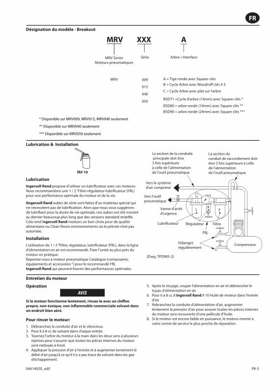
Désignation du modèle - Breakout
MRV XXX A
009
015
040
050
MRV SeriesMoteurs pneumatiques
A = Tige ronde avec Square-clésB = Cycle Arbre avec Woodruff clés # 3
C = Cycle Arbre avec plat sur l'arbre
B5D71 =Cycle d'arbre (14mm) avec Square-clés *
B5D80 = arbre ronde (19mm) avec Square clés **B5D90 = arbre ronde (24mm) avec Square clés ***
MRV
Arbre / InterfaceSérie
* Disponible sur MRV009, MRV015, MRV040 seulement
** Disponible sur MRV040 seulement
*** Disponible sur MRV050 seulement
IR# 10
Lubrication
Ingersoll Rand propose d’utiliser un lubrifi cateur avec ces moteurs. Nous recommandons une 1 / 2 “Filtre-régulateur-lubrifi cateur (FRL) pour une performance optimale du moteur et de la vie.
IIngersoll Rand aubes de série sont faites d’un matériau spécial qui ne nécessitent pas de lubrifi cation. Alors que nous vous suggérons de lubrifi ant pour la durée de vie optimale, nos aubes ont été montré au dernier beaucoup plus long que des versions standard stratifi é. Cela rend Ingersoll Rand moteurs un bon choix pour de qualité alimentaire ou Clean Room environnements où le pétrole n’est pas autorisée.
Installation
L’utilisation de 1 / 2 “Filtre, régulateur, lubrifi cateur (FRL), dans la ligne d’alimentation en air est recommandé. Fixer l’unité au plus près du moteur en pratique.Reportez-vous à moteur pneumatique Catalogue (composants, équipements et accessoires “) pour le recommandé FRL Ingersoll Rand qui peuvent fournir des performances optimales.
FLR
La section de la conduite principale doit être 3 fois supérieure à celle de l'alimentation de l'outil pneumatique.
Vers le systèmed'air comprimé
Vers l'outil pneumatique
Lubrificateur
Vanne d'arrêt d'urgence
Régulateur Filtre
Compresseur
FRL
Vidangezrégulièrement
La section du conduit de raccordement doit être 2 fois supérieure à celle de l'alimentation de l'outil pneumatique.
(Dwg. TPD905-2)
Entretien du moteur
Opération
AVIS
Si le moteur fonctionne lentement, rincez-le avec un chiff on
propre, non-toxique, non infl ammable commerciale solvant dans
un endroit bien aéré.
Pour rincer le moteur:
Débranchez la conduite d’air et le silencieux.Pour 6 à 8 cc de solvant dans chaque entrée.Tournez l’arbre du moteur à la main dans les deux sens à plusieurs reprises pour s’assurer que toutes les pièces internes du moteur sont nettoyés à fond.Appliquer la pression d’air à l’entrée et à augmenter lentement le débit d’air jusqu’à ce qu’il n’y a pas trace de solvant dans les gaz d’échappement.
1.2.3.
4.
Après le rinçage, couper l’alimentation en air et débrancher le tuyau d’alimentation en air.Pour 6 à 8 cc d Ingersoll Rand # 10 Huile de moteur dans l’entrée d’air.Rebranchez la conduite d’alimentation d’air, augmenter lentement la pression d’air pour assurer toutes les pièces internes du moteur sera recouverte d’une pellicule d’huile.Si le moteur est encore faible en puissance, le moteur revenir à votre centre de service le plus proche de réparation.
5.
6.
7.
8.
Lubrication & Installation
8 04614020_ed5
EN
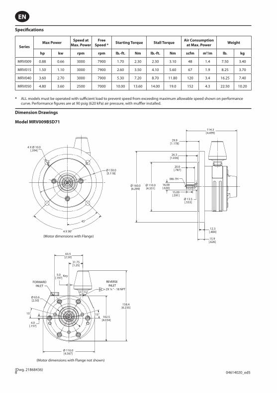
Specifi cations
SeriesMax Power
Speed at
Max. Power
Free
Speed *Starting Torque Stall Torque
Air Consumption
at Max. PowerWeight
hp kw rpm rpm lb.-ft. Nm lb.-ft. Nm scfm m3/m lb. kg
MRV009 0.88 0.66 3000 7900 1.70 2.30 2.30 3.10 48 1.4 7.50 3.40
MRV015 1.50 1.10 3000 7900 2.60 3.50 4.10 5.60 67 1.9 8.25 3.70
MRV040 3.60 2.70 3000 7900 5.30 7.20 8.70 11.80 120 3.4 16.25 7.40
MRV050 4.80 3.60 2500 7000 10.00 13.60 14.00 19.0 152 4.3 22.50 10.20
* ALL models must be operated with suffi cient load to prevent speed from exceeding maximum allowable speed shown on performance curve. Performance fi gures are at 90 psig (620 kPa) air pressure, with muffl er installed.
Dimension Drawings
Model MRV009B5D71
5.0[.197]
63.5[2.50]
2X ¼ “ - 18 NPT
31.75[1.25]
102.5[4.034]
158.4[6.235]
Ø 63.6[2.50]
Ø 160.0[6.299]
Ø 110.0[4.331]
Ø 13.5[.533]
12.3[.484]
15.9[.626]
16.00[.630]
15.00[.591]
114.3[4.499]
29.9[1.178]
26.3[1.036]
M6-7H
20.0[.787]
15° 15°
Ø 116.0[4.567]
4.0[.157]
Key
Ø 130.0[5.118]
4 X Ø 10.0[.394]
4 X 90°
45°
H
REVERSE INLET
FORWARDINLET
(Motor dimensions with Flange not shown)
(Motor dimensions with Flange)
(Dwg. 21868436)

04614020_ed5 9
EN
Model MRV009C
63.5[2.50]
Ø 85.8[3.378]
4.0[.157]
Ø 63.6[2.50]
Ø 44.45[1.75]
Ø 12.7[.50]
8.0 Min[.315]
11.5[.453]
31.75[1.25]
Ø 116.0[4.567]
102.5[4.034]
158.4[6.235]
116.4[4.582]
72.7[2.862]
15.8[.622]
28.52[1.123]
25.4[1.00]
M6-6H3 Places
2X ¼” - 18 NPT
15° 15°
H
REVERSE INLETFORWARD
INLET
(Dwg. 21868419)
Model MRV015A
6.37[161.90]
2X ¼ “- 18 NPT
4.02[102.00]
Ø 115.0[4.53]
Ø 85.8[3.38]
Ø 15.875[.625]
Ø 57.15[2.25]
17.90[.705]
32.0[1.26]
1 to 3 mm Gap
50.5[1.99]
63.5[2.50]
158.9[6.26]
11.00 Min[.433]
M6 -6H3 Places
104.9[4.13]
Ø 76.2[3.00]
4.00[.16]
30°30°
46.5[1.83]
63.5[2.50]
31.75[1.25]
4.775[3⁄16]
KEY
H
REVERSE INLET
FORWARD INLET
(Dwg. 04614053)
10 04614020_ed5
EN
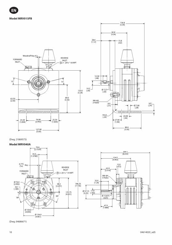
Model MRV015FB
127.00[5.00]
63.50[2.50]
89.0[3.50]
133.0[5.24]
136.8[5.39]
82.8[3.26]
28.6[1.12] 15.8
[.62]
12.30[.48]
Ø 12.7[.50]
Ø 7.00[.28]
R 6.0[.24]
14.2[.56]
M6-6H3 Holes 8.0
[.31]
24.00[.94]
89.0[3.50]
27.00[1.06]
6.0[.24]
76.00[2.992]
25.50[1.004]
25.50[1.004]
Woodruff Key # 3
H
REVERSE INLET
2X¼ “-18 NPT
15° 15°
FORWARDINLET
(Dwg. 21869573)
Model MRV040A70.0
[2.7559]
Ø 76.0[2.992]
Ø 57.15[2.25]
Ø 15.875[.625]
32.0[1.26]
12.0[.472]
M6-6H3 Holes
63.9[2.516]
124.5[4.903]
204.1[8.035]
17.9[.705]
47.9[1.886]
Ø 104.0[4.094]
Ø 126.0[4.961]
4.8[.189]
58.2[2.291]
125.75[4.951]
196.25[7.726]
35.0[1.3780]
4.775[3⁄16] Key
2X ½ “-14 NPT
30º30º
H
REVERSE INLET
FORWARDINLET
(Dwg. 04686671)
04614020_ed5 11
EN
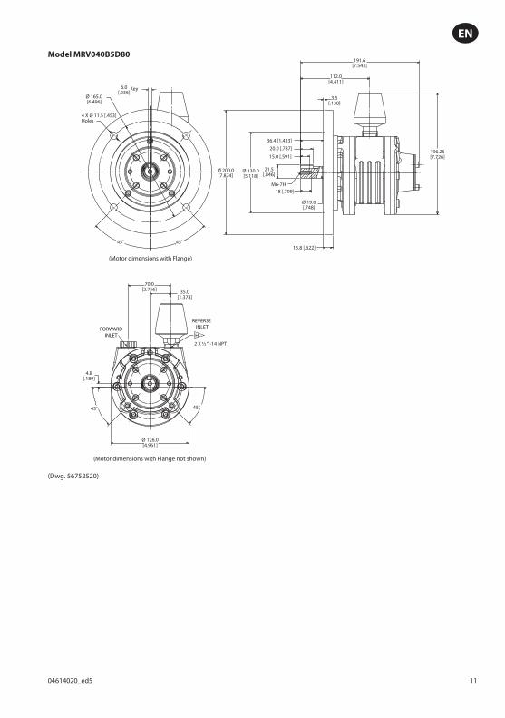
Model MRV040B5D80
4 X Ø 11.5 [.453]Holes
Ø 165.0 [6.496]
70.0[2.756]
Ø 126.0[4.961]
Ø 200.0[7.874]
196.25[7.726]
191.6[7.543]
Ø 130.0[5.118]
Ø 19.0[.748]
21.5[.846]
M6-7H
36.4 [1.433]20.0 [.787]
15.0 [.591]
18 [.709]
15.8 [.622]
112.0[4.411]
3.5[.138]
4.8[.189]
2 X ½ “ -14 NPT
35.0[1.378]
6.0[.236]
Key
45°
45° 45°
45°
H
REVERSE INLETFORWARD
INLET
(Motor dimensions with Flange not shown)
(Motor dimensions with Flange)
(Dwg. 56752520)
12 04614020_ed5
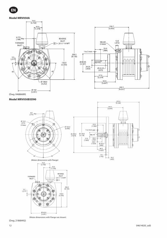
EN
Model MRV050A70.0
[2.756]
150.7[5.935]
M6-6H3 Holes
1 to 3 mm
5.5[.217]
206.5[8.130]
136.0[5.354]
35.0[1.378]
2X ½”-14 NPT
4.775[.188]
Ø 108.0[4.252]
Ø 80.95[3.187]
25.0[.984]
12.0[.472]
Ø 22.23[.875]
24.35[.959]
57.9[2.279]
93.9[3.697]
242.1[9.531]Ø 142
[5.591]
Key
45° 45°
H
REVERSE INLET
FORWARDINLET
(Dwg. 04686689)
Model MRV050B5D90
70.0[2.756]
233.4[9.189]
143.3[5.644]
32.0[1.260]
M8-7H
1 to 3mm gap
27.0[1.063]
20.0[.787]26.0
[1.024]
5.5[.217]
8.0[.315]
Ø 12.0[.472]
136.0[5.354]
Ø142.0[5.591]
Ø 165.0[6.496]
Ø 200.0[7.874]
Ø 130.0[5.118]
Ø 24.0[.945]
46.3[1.823]
3.6[.142]
16.3[.642]
206.5[8.130]
35.0[1.378]
2X ½ “-14 NPT
Key
4 Holes
45˚ 45˚
H
REVERSE INLETFORWARD
INLET
(Motor dimensions with Flange not shown)
(Motor dimensions with Flange)
(Dwg. 21868492)
04614020_ed5 13
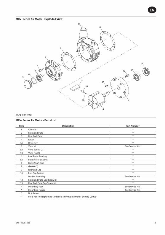
MRV- Series Air Motor - Exploded View
6A6
910
1
11
8
3
13
8
12
4A
2
4
7
5
5A
5B
(Dwg. TPM1002)
MRV- Series Air Motor - Parts List
Item Description Part Number
1 Cylinder **2 Front End Plate **3 Rear End Plate **4 Rotor **
4A Drive Key **5 Vane (4) See Service Kits
5A Vane Spring (2) **5B Vane Pin (4) **6 Rear Rotor Bearing **
6A Front Rotor Bearing **7 Rotor Shaft Seal **8 Gasket (2) **9 Rear End Cap **
10 End Cap Gasket **11 Muffl er Assembly See Service Kits12 Front End Plate Cap Screw (6) **13 Rear End Plate Cap Screw (6) *** Mounting Foot See Service Kits* Mounting Flange See Service Kits* Not shown** Parts not sold separately (only sold in complete Motor or Tune-Up Kit)
EN
14 04614020_ed5
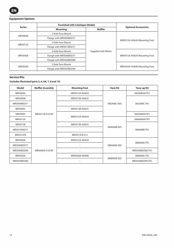
Equipment Options
SeriesFurnished with Catalogue Models
Optional AccessoriesMounting Muffl er
MRV009A2 Hole Face Mount
Supplied with Motor
MRV015A-AH634 Mounting FootFlange with MRV009B5D71
MRV015A2 Hole Face Mount
Flange with MRV015B5D71
MRV040A
2 Hole Face Mount
MRV015A-AH634 Mounting FootFlange with MRV040B5D71
Flange with MRV040B5D80
MRV050A2 Hole Face Mount
MRV050A-AH640 Mounting FootFlange with MRV050B5D90
Service Kits
(includes illustrated parts 5, 6, 6A, 7, 8 and 10)
Model Muffl er Assembly Mounting Foot Vane Kit Tune-up Kit
MRV009A
MRV015A-010-RP
MRV015A-AH634
SM2AMC-005
SM2AMAN-TK1
MRV009B MRV015B-AH635
SM2AMC-TK1MRV009B5D71 -
MRV009C MRV015B-AH635
MRV009FMRV015A-AH634
SM2AMAN-TK1
MRV015A
SM4AMB-005
SM4AMAN-TK1
MRV015B MRV015B-AH635
SM4AMB-TK1MRV015B5D71 -
MRV015FB MRV015FB-013
MRV040A
MRV040A-010-RP
MRV015A-AH634
SM6AMA-005SM6AMA-TK1
MRV040B5D71 -
MRV040B5D80 - MRV040B5D80-TK1
MRV050A MRV050A-AH640SM8AMA-005
SM8AMA-TK1
MRV050B5D90 - MRV050B5D90-TK1
EN
04614020_ed5 15
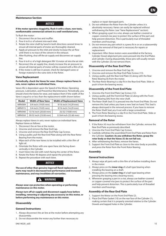
NOTICE
If the motor operates sluggishly, fl ush it with a clean, non-toxic,
nonfl ammable commercial solvent in a well ventilated area.
To fl ush the motor:Disconnect the air line and muffl er.Pour 6 to 8 cc of solvent into each inlet.Rotate the rotor shaft by hand in both directions several times to ensure all internal parts of motor are thoroughly cleaned.Apply air pressure to the inlet and slowly increase the air fl ow until there is no trace of the solvent in the exhaust.After fl ushing, shut off the air supply and disconnect air supply line.Pour 6 to 8 cc of a high detergent IR# 10 motor oil into the air inlet.Reconnect the air supply line, slowly increase the air pressure to ensure all internal parts of motor will be covered with a fi lm of oil.If the motor is still low in power, check for damaged vanes or foreign material in the vane slots in the Rotor.
Vane Replacement
Periodically, check the Vanes for wear. Always replace Vanes in
sets, never replace an individual Vane.
Vanes life is dependant upon the Speed of the Motor, Operating pressure, Lubrication, and Preventive Manintenance. Periodically, you should check the Vanes for wear, and replace them if the width of the Vane is equal to or less than the replacement width shown below:
Model Width of New Vane Width of Replacement Vane
MRV009 3/4 inch (19.05 mm) 9/16 inch (14.29 mm)
MRV015 3/4 inch (19.05 mm) 9/16 inch (14.29 mm)
MRV040 13/16 inch (20.60 mm) 25/32 (19.80 mm)
MRV050 29/32 inch (23.00 mm) 57/64 inch (22.60 mm)
Always replace Vanes in sets; never replace an individual Vane. Replace Vanes as follows:
Disconnect the air line at the motor.Unscrew and remove the Rear End Cap.Unscrew and remove the Rear End Plate Cap Screws.Using a puller, pull the Rear End Plate along with the Rear Rotor Bearing from the motor.Wipe each of the new Vanes to be installed with a thin fi lm of light oil.Orientate the Rotor with one open Vane slot facing down vertically in the Cylinder.Insert Vane into slot with notch facing the center of the Rotor.Rotate the Rotor 90 degrees and repeat the procedure.Repeat the procedure with each Vane.
NOTICE
The use of other than genuine Ingersoll Rand replacement
parts may result in decreased tool performance and increased
maintenance, and may invalidate all warranties.
WARNING
Always wear eye protection when operating or performing
maintenance on this motor.
Always turn off air supply and disconnect supply hose before
installing, removing or adjusting any accessory on this motor, or
before performing any maintenance on this motor.
Disassembly
General Instructions
Always disconnect the air line at the motor before attempting any disassembly.Do not disassemble the motor any further than necessary to
1.2.3.
4.
5.
6.7.
8.
1.2.3.4.
5.
6.
7.8.9.
1.
2.
replace or repair damaged parts.Do not withdraw the Rotor from the Cylinder unless it is absolutely necessary. Vanes can easily be replaced without withdrawing the Rotor. (see “Vane Replacement” section).When grasping a part in a vise, always use leather-covered or copper-covered vise jaws to protect the surface of the part and help prevent distortion. This is particularly true of threaded members and housings.Do not remove any part which is a press fi t in or on a subassembly unless the removal of that part is necessary for repairs or replacement.Important: After these motors were assembled at the factory, Cylinder Dowel alignment pins were pressed into the End Plates and Cylinder. During disassembly, these pins will usually remain with the Cylinder. Do not remove them.
Disassembly of the Rear End Plate
Unscrew and remove the Rear End Cap (9).Unscrew and remove the Rear End Plate Screws (13).Using a puller, pull the Rear End Plate (3) along with the Rear Rotor Bearing (6) from the motor.The Rear Rotor Bearing is a slip fi t in the Rear End Plate. Slide or push it from the bearing recess.
Disassembly of the Front End Plate
Unscrew the Front End Plate Cap Screws (12).Using a puller, pull the Front End Plate (2) along with the Front Rotor Bearing (6A) from the rotor shaft.The Rotor Shaft Seal (7) is pressed into the Front End Plate. Do not remove this Seal unless you have a new Seal on hand. This Seal is always destroyed in the removal process. If you have to remove the Rotor Shaft Seal, pry it out with a large screwdriver.The Front Rotor Bearing is a slip fi t in the Front End Plate. Slide or push it from the bearing recess.
Removal of the Rotor
If the Rotor (4) must be withdrawn from the Cylinder, remove the Rear End Plate as previously described.Unscrew the Front End Plate Cap Screws.Carefully withdraw the assembled Front End Plate and Rotor from the Cylinder. Caution: As you withdraw the Rotor, grasp the
rotor body so that the Vanes (5) do not fall out.
After withdrawing the Rotor, remove the Vanes.Support the Front End Plate as close to the rotor body as possible, and press the Rotor from the Front Rotor Bearing.
Assembly
General Instructions
Always wipe all parts with a thin fi lm of oil before installing them in the motor.Always press on the inner ring of a ball-type bearing when installing the bearing on a shaft.Always press on the outer ring of a ball-type bearing when pressing the bearing into a bearing recess.Whenever grasping a part in a vise, always use leather-covered or copper-covered vise jaws to protect the surface of the part and help prevent distortion. This is particularly true of threaded members and housings.
Assembly of the Rear End Plate
Support the Motor on the Front End Plate (2).Place End Plate Gasket (10) on the rear face of the Cylinder (1), making certain that it is properly oriented relative to the Cylinder Dowels and tapped holes in the Cylinder.
3.
4.
5.
6.
1.2.3.
4.
1.2.
3.
4.
1.
2.3.
4.5.
1.
2.
3.
4.
1.2.
Maintenance Section
EN
16 04614020_ed5
NOTICE
If you are installing a new Gasket, you will have to punch or cut
two holes in it to accommodate the Cylinder Dowels. Do this
by placing the Gasket on the Gasket on the Rear End Plate to
determine the location of the dowel holes. Use a proper size
gasket punch to cut the required dowel holes.
3. Align the dowel holes in the Rear End Plate (3) with Cylinder Dowels in the Cylinder and, using a plastic hammer, tap the Rear End Plate into place against the Gasket.
4. Using a sleeve that contacts only the inner ring of the Bearing, press the Rear Rotor Bearing (6) onto the rotor shaft until it seats in the bearing recess in the Rear End Plate.
CAUTION
Do not bind the End Plate against the Rotor.
5. Rotate Rotor (4) by hand. It should rotate freely with no binding or rubbing against the Cylinder. If the Rotor rubs or binds, tap the top edge of the Rear End Plate with a plastic hammer in the area midway between the inlet and outlet ports. Tap the End Plate gently. The Rotor needs only 0.0015 inch (0.038 mm) clearance from the top of the Cylinder. If the Rotor continues to rub, it may be contacting the Front End Plate due to pressing on the Rear Rotor Bearing. Lightly tap the output end of the rotor shaft with a plastic hammer. The Rotor needs about 0.002 inch (0.05 mm) clearance between the rotor body and each End Plate.
6. When the Rotor turns freely, install the End Plate Cap Screws (13). Tighten them to 8 to 10 ft-lb (10.8 to 13.5 Nm).
7. Slip End Cap Gasket (10) over the threaded hub of Rear End Cap (9) and thread the Rear End Cap into Rear End Plate.
Assembly of the Front End Plate
Support the Motor on the Rear End Plate.Place an End Plate Gasket on the front face of the Cylinder, making certain that is properly oriented relative to the Cylinder Dowels and tapped holes in the Cylinder.
NOTICE
If you are installing a new Gasket, you will have to punch or cut
two holes in it to accommodate the Cylinder Dowels. Do this
by placing the Gasket on the Gasket on the Rear End Plate to
determine the location of the dowel holes. Use a proper size
gasket punch to cut the required dowel holes.
3. Align the dowel holes in the Front End Plate with the Cylinder Dowels in the Cylinder and, using a plastic hammer, tap the Front End Plate into place against the Gasket.
4. Using a sleeve that contacts only the inner ring of the Bearing, press the Front Rotor Bearing (6A) onto rotor shaft until it seats in the bearing recess in the Front End Plate.
5. Rotate the Rotor by hand. It should rotate freely with no binding or rubbing against the Cylinder. If the Rotor rubs or binds, tap the top edge of the Front End Plate with a plastic hammer in the area midway between the inlet and outlet ports. Tap the End Plate gently. The Rotor needs only 0.0015 inch (0.038 mm) clearance from the top of the Cylinder. If the Rotor continues to rub, it may be contacting the Rear End Plate due to pressing on the Front Rotor Bearing. Remove the Rear End Cap and lightly tap the end of the rotor hub with a plastic hammer. The Rotor needs about 0.002 inch (0.05 mm) clearance between the rotor body and each End Plate.
6. When the Rotor turns freely, install the Front End Plate Cap Screws (12). Tighten them to 8 to 10 ft-lb (10.8 to 13.5 Nm).
7. Moisten the lip of a new Rotor Shaft Seal (7) with O-Ring lubricant, and press the Seal, lip side fi rst, into the Front End Plate until the trailing face of the Seal is fl ush with the face of the End Plate.
1.2.
Assembly of the Motor
Position the Rotor vertically on the table of an arbor press so that the short hub is upward.Place the Rear End Plate, fl at side fi rst, on the short hub of the Rotor.Place a 0.002 inch (0.05 mm) thick shim on each side of the Rotor between the rotor body and the Rear End Plate.Using a sleeve that contacts only the inner ring of the Bearing, press the Rear Rotor Bearing (6) onto the hub of the Rotor until it seats in the bearing recess in the Rear End Plate.Withdraw the shims.Stand the assembled Rotor and End Plate upright on on the hub of the Rear End Plate.Moisten each Vane (5) with fi lm of light oil.Place a Vane, notched side fi rst, in each vane slot.Place an End Plate Gasket on the rear face of the Cylinder, making certain that it is properly oriented relative to the Cylinder Dowels and tapped holes in the Cylinder.
NOTICE
If you are installing a new Gasket, you will have to punch or cut
two holes in it to accommodate the Cylinder Dowels. Do this
by placing the Gasket on the Rear End Plate to determine the
location of the dowel holes. Use a proper size gasket punch to
cut the required dowel holes.
10. Slide the assembled Rotor and Rear End Plate into the Cylinder until the End Plate contacts the Cylinder Dowels.
11. Using a wire hook inserted between the End Plate Cylinder, pull the rubber band free of the rotor, thus leaving the Vanes, Vane Springs and Vane Pins trapped in the Cylinder.
12. Align the dowel holes in the Rear End Plate with the Cylinder Dowels in the Cylinder and, using a plastic hammer, tap the Rear End Plate into place against the Gasket.
13. Install the Front End Plate as described in Steps 1, 2, 3 and 4 in the section titled Assembly of the Front End Plate.
14. Rotate the Rotor by hand. It should rotate freely with no binding or rubbing against the Cylinder. If the Rotor rubs or binds, tap the top edge of the Rear End Plate with a plastic hammer in the area midway between the inlet and outlet ports. Tap the End Plates gently. The Rotor needs only 0.0015 inch (0.038 mm) clearance from the top of the Cylinder. If the Rotor continues to rub, it may be contacting the Rear End Plate due to pressing on the Front Rotor Bearing. Lightly tap the end of the rotor hub with a plastic hammer. The Rotor needs about 0.002 inch (0.05 mm) clearance between the rotor body and each End Plate.
15. When the Rotor turns freely, install the End Plate Cap Screws (12) and tighten them to 8 to 10 ft-lb (10.8 to 13.5 Nm).
16. Install the Rotor Shaft Seal (7) and Front End Cap as described in Step 7 in the section titled Assembly of the Front End Plate.
17. Install the Rear End Cap (9) as described in Step 7 in the section titled Assembly of the Rear End Plate.
18. Again, check the Rotor to see that it rotates freely. Make certain it is rotating freely before connecting the air supply line.
1.
2.
3.
4.
5.6.
7.8.9.
EN

04614020_ed5 17
Troubleshooting Guide
Trouble Probable Cause Solution
Low power or low free speed Low air pressure at the inlet Check air pressure at the inlet. For top performance and durability of parts, the air pressure must be 90 psig (6.2 bar/620 kPa) at the inlet.
Worn or broken Vanes Install a new set of Vanes.
Improper lubrication or dirt building up in the Motor
Lubricate as instructed under LUBRICATION. If this does not help, fl ush the Motor as instructed under OPERATION.
Rough operation Worn or broken Rotor Bearings Examine each Bearing. Install new bearing where necessary.
Scoring of End Plates and/or Cylinder Rotor does not have proper clearance Refer to Assembly of Motor section. (Step 16)
Parts and Maintenance
NOTICE
The use of other than genuine Ingersoll Rand replacement parts may result in safety hazards, decreased motor performance, and
increased maintenance, and may invalidate all warranties.
Ingersoll Rand is not responsible for customer modifi cation of motors for applications on which Ingersoll Rand was not consulted.
Repairs should be made only by authorized trained personnel. Consult your nearest Ingersoll Rand Authorized Service center.
When the life of the tool has expired, it is recommended that the tool be disassembled, degreased and parts be separated by material so that they can be recycled.
Manuals can be downloaded from www.ingersollrandproducts.com
Refer all communications to the nearest Ingersoll Rand Offi ce or Distributor.
EN

Notes:

Notes:

www.ingersollrandproducts.com
© 2011 Ingersoll Rand