operation and maint for energy efficiency
TRANSCRIPT

Cooling Tower Operation and Maintenance is the Key for Improved Energy Efficiency

Cooling Tower Operation and Maintenance is the Key for Improved Energy Efficiency
Principle of Operation and Layout Principle of Operation and Layout –– Kavita AnujeKavita AnujeMaintenanceMaintenance Regimens Regimens –– Trevor Trevor HeggHeggOperating Strategies & Water Treatment Operating Strategies & Water Treatment -- Paul LindahlPaul Lindahl

Cooling Tower Operation and Maintenance for Improved Energy Efficiency
Terminology
Forced Draft CounterflowForced Draft Counterflow
Induced Draft CounterflowInduced Draft Counterflow
Forced Draft CrossflowForced Draft Crossflow
Induced Draft Crossflow
Open Cooling TowersOpen Cooling Towers
Closed Circuit Closed Circuit Cooling TowersCooling Towers
Induced Draft Crossflow
Cooling Tower Operation and Maintenance for Improved Energy Efficiency
Open Cooling TowerOpen Cooling TowerAn evaporative piece of equipment that exposes An evaporative piece of equipment that exposes water directly to the cooling atmosphere, thereby water directly to the cooling atmosphere, thereby
transferring the source heat load directly to the air.transferring the source heat load directly to the air.

Cooling Tower Operation and Maintenance for Improved Energy Efficiency
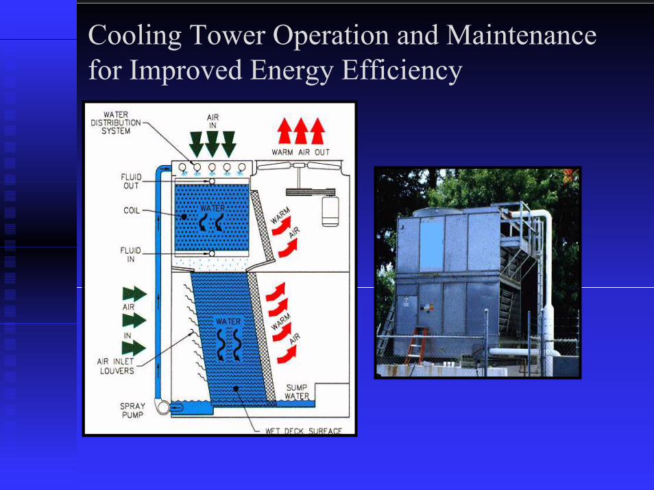
Closed Circuit Cooling TowerClosed Circuit Cooling TowerAn evaporative piece of equipment that contains twoAn evaporative piece of equipment that contains twoseparate fluid circuits. The first is an external circuitseparate fluid circuits. The first is an external circuit
where water is exposed to the atmosphere as itwhere water is exposed to the atmosphere as itcascades over the tubes of a coil bundle. The secondcascades over the tubes of a coil bundle. The secondis an internal circuit in which the fluid to be cooledis an internal circuit in which the fluid to be cooled
circulates inside the tubes of the coil bundle.circulates inside the tubes of the coil bundle.

Cooling Tower Operation and Maintenance for Improved Energy Efficiency
Forced DraftForced DraftType of mechanical draft tower in which one orType of mechanical draft tower in which one or
more fans are located at the air inlet to force air into more fans are located at the air inlet to force air into the cooling tower.the cooling tower.

Cooling Tower Operation and Maintenance for Improved Energy Efficiency
Induced DraftInduced DraftType of mechanical draft tower in which one orType of mechanical draft tower in which one or
more fans are located in the air outlet to induce air more fans are located in the air outlet to induce air through the air inlets.through the air inlets.

Cooling Tower Operation and Maintenance for Improved Energy Efficiency
CounterflowCounterflowIn a counterflow cooling tower, the air enters at theIn a counterflow cooling tower, the air enters at the
base of the tower, flows upward and interfacesbase of the tower, flows upward and interfacescounter currently with the falling hot water.counter currently with the falling hot water.

Cooling Tower Operation and Maintenance for Improved Energy Efficiency
CrossflowCrossflowIn a crossflow cooling tower, the air flowsIn a crossflow cooling tower, the air flows
horizontally through the cooling tower and interfaceshorizontally through the cooling tower and interfacesperpendicularly with the falling hot water.perpendicularly with the falling hot water.

Cooling Tower Operation and Maintenance for Improved Energy Efficiency
Air Flow Direction
Water Flow Direction

Cooling Tower Operation and Maintenance for Improved Energy Efficiency
Air Flow Direction
Water Flow Direction
Fluid Inlet
Fluid Outlet

Cooling Tower Operation and Maintenance for Improved Energy Efficiency
Air Flow Direction
Water Flow Direction

Cooling Tower Operation and Maintenance for Improved Energy Efficiency
Air Flow Direction
Water Flow Direction
Fluid Inlet
Fluid Outlet

Cooling Tower Operation and Maintenance for Improved Energy Efficiency
Air Flow Direction
Water Flow Direction

Cooling Tower Operation and Maintenance for Improved Energy Efficiency
Air Flow Direction
Water Flow Direction

Cooling Tower Operation and Maintenance for Improved Energy Efficiency
Air Flow Direction
Water Flow Direction
Cooling Tower Operation and Maintenance for Improved Energy Efficiency

Cooling Tower Operation and Maintenance for Improved Energy Efficiency
Water Distribution SystemsWater Distribution Systems–– Gravity distribution systemGravity distribution system–– Spray distribution systemSpray distribution system

Cooling Tower Operation and Maintenance for Improved Energy Efficiency
Gravity Distribution SystemGravity Distribution System–– Open basinsOpen basins–– Large orifice, 360° nozzlesLarge orifice, 360° nozzles–– Easily accessed for maintenance Easily accessed for maintenance –– Basin water level used to balance flowBasin water level used to balance flow

Cooling Tower Operation and Maintenance for Improved Energy Efficiency
Spray Distribution SystemSpray Distribution System–– Pressurized systemPressurized system–– Large orifice, 180° directional nozzlesLarge orifice, 180° directional nozzles–– Spray header and branchesSpray header and branches–– 2 PSI spray pressure at the header inlet2 PSI spray pressure at the header inlet

Cooling Tower Operation and Maintenance for Improved Energy Efficiency
Heat Transfer Surface (Fill or Wet Deck)Heat Transfer Surface (Fill or Wet Deck)–– PVC wet deck surfacePVC wet deck surface–– Specialty wet deck materialsSpecialty wet deck materials

Cooling Tower Operation and Maintenance for Improved Energy Efficiency
PVC Wet Deck SurfacePVC Wet Deck Surface–– Impervious to rot, decay, fungus and biological Impervious to rot, decay, fungus and biological
attackattack–– 130°F limitation for counterflow cooling towers130°F limitation for counterflow cooling towers–– 120°F limitation for crossflow cooling towers 120°F limitation for crossflow cooling towers

Cooling Tower Operation and Maintenance for Improved Energy Efficiency
High Temperature PVC Wet Deck SurfaceHigh Temperature PVC Wet Deck Surface–– Impervious to rot, decay, fungus and biological Impervious to rot, decay, fungus and biological
attackattack–– 150°F limitation for counterflow cooling towers150°F limitation for counterflow cooling towers–– 135°F limitation for crossflow cooling towers 135°F limitation for crossflow cooling towers

Cooling Tower Operation and Maintenance for Improved Energy Efficiency
Specialty Wet Deck SurfacesSpecialty Wet Deck Surfaces–– Available for process type applicationsAvailable for process type applications
–– Galvanized or stainless steel wet deck Galvanized or stainless steel wet deck surfacesurface
–– Dirty water fillDirty water fill–– Splash fillSplash fill
–– Contact equipment manufacturer for Contact equipment manufacturer for performance information performance information

Cooling Tower Operation and Maintenance for Improved Energy Efficiency
Air Moving SystemsAir Moving Systems–– Axial fansAxial fans–– Centrifugal fansCentrifugal fans

Cooling Tower Operation and Maintenance for Improved Energy Efficiency
Axial FansAxial Fans–– Over 80% of cooling towers on HVAC Over 80% of cooling towers on HVAC
applications use axial fansapplications use axial fans–– High volume/ Low static pressureHigh volume/ Low static pressure–– High efficiencyHigh efficiency–– Low energy consumptionLow energy consumption–– Improved sound ratingsImproved sound ratings

Cooling Tower Operation and Maintenance for Improved Energy Efficiency
Centrifugal FansCentrifugal Fans–– High volume/Static pressuresHigh volume/Static pressures
–– Indoor installationsIndoor installations–– Inlet or discharge ductworkInlet or discharge ductwork
–– High energy consumptionHigh energy consumption–– Quiet operationQuiet operation–– Tight layout requirementsTight layout requirements

Cooling Tower Operation and Maintenance for Improved Energy Efficiency
1,500 GPM of Water1,500 GPM of Water95°F EWT95°F EWT85°F LWT85°F LWT78°F EWB
Counterflow, centrifugal Counterflow, centrifugal fan unit requires 60 HPfan unit requires 60 HPCrossflow, axial fan unit Crossflow, axial fan unit requires 30 HPrequires 30 HPAxial fan units require less Axial fan units require less HP than centrifugal fan HP than centrifugal fan units
78°F EWB
units

Cooling Tower Operation and Maintenance for Improved Energy Efficiency
Drive SystemsDrive Systems–– Belt driveBelt drive–– Gear driveGear drive

Cooling Tower Operation and Maintenance for Improved Energy Efficiency
Proven performance on cooling Proven performance on cooling tower applicationtower applicationEfficient and designed for moist Efficient and designed for moist air applicationsair applications

Cooling Tower Operation and Maintenance for Improved Energy Efficiency
Cooling Tower Equipment LayoutCooling Tower Equipment Layout

Cooling Tower Operation and Maintenance for Improved Energy Efficiency
Prevent warm air or drift from being introduced into fresh Prevent warm air or drift from being introduced into fresh air intakes or from being carried over populated areasair intakes or from being carried over populated areasConsider the potential for plumeConsider the potential for plumeNote the direction of the prevailing windsNote the direction of the prevailing windsEnsure adequate supply of fresh air to the air intakeEnsure adequate supply of fresh air to the air intakeProvide adequate space for piping and proper servicing and Provide adequate space for piping and proper servicing and maintenancemaintenanceTop of the unit discharge must be at least level with the Top of the unit discharge must be at least level with the adjacent wall adjacent wall

Cooling Tower Operation and Maintenance for Improved Energy Efficiency
Layout ExamplesLayout Examples–– Adjacent to a wall or buildingAdjacent to a wall or building–– In an enclosureIn an enclosure–– Adjacent to a louvered or slotted wallAdjacent to a louvered or slotted wall

Cooling Tower Operation and Maintenance for Improved Energy Efficiency
NominalNominal–– 1,500 GPM 95/85/781,500 GPM 95/85/78
1°F Recirculation1°F Recirculation–– 1,384 GPM 95/85/791,384 GPM 95/85/79–– 8% 8% DerateDerate
2°F Recirculation2°F Recirculation–– 1,258 GPM 95/85/801,258 GPM 95/85/80–– 19% 19% DerateDerate
Prevailing Wind
Induced DraftCooling Tower

Cooling Tower Operation and Maintenance for Improved Energy Efficiency
NominalNominal–– 1,500 GPM 95/85/781,500 GPM 95/85/78
1°F Recirculation1°F Recirculation–– 1,500 GPM 1,500 GPM
95.77/85.77/7995.77/85.77/792°F Recirculation2°F Recirculation
–– 1,500 GPM 1,500 GPM 96.56/886.56/8096.56/886.56/80
Prevailing Wind
Induced DraftCooling Tower

Cooling Tower Operation and Maintenance for Improved Energy Efficiency
Every 1°F Increase in CWT Corresponds to aEvery 1°F Increase in CWT Corresponds to a2% Decrease in Chiller Efficiency2% Decrease in Chiller Efficiency

Cooling Tower Operation and Maintenance for Improved Energy Efficiency
Correct cooling tower Correct cooling tower installation when installation when located adjacent to a located adjacent to a building or wallbuilding or wall
Induced DraftCooling Tower

Cooling Tower Operation and Maintenance for Improved Energy Efficiency
What is the distance What is the distance between the wall and between the wall and the air inlet to the the air inlet to the cooling tower?cooling tower?
–– Maximum air velocity Maximum air velocity should not exceed 300 should not exceed 300 FPMFPM
–– Air entry envelope Air entry envelope consists of top and two consists of top and two sidessides
–– Based on 125,900 Based on 125,900 CFM, an inlet height of CFM, an inlet height of 10 feet and an air inlet 10 feet and an air inlet length of 12 feet, the length of 12 feet, the distance to the wall is distance to the wall is 6.5 feet6.5 feet
Induced DraftCooling Tower
D

Cooling Tower Operation and Maintenance for Improved Energy Efficiency
When cooling towers When cooling towers are positioned with air are positioned with air inlets facing each inlets facing each other, the distance other, the distance between cooling between cooling towers is 2 x Dtowers is 2 x D

Cooling Tower Operation and Maintenance for Improved Energy Efficiency
What is the distance between What is the distance between the wall and the air inlet to the the wall and the air inlet to the cooling tower for a well cooling tower for a well enclosure?enclosure?
–– Maximum air velocity should not Maximum air velocity should not exceed 400 FPMexceed 400 FPM
–– Center the cooling tower within Center the cooling tower within the enclosure for uniform air flow the enclosure for uniform air flow to the air inletsto the air inlets
–– Air entry is from the top onlyAir entry is from the top only–– Based on 125,900 CFM, an air Based on 125,900 CFM, an air
entry area as indicated by the entry area as indicated by the shaded area, the distance to the shaded area, the distance to the wall is 8 feetwall is 8 feet
D D
Well Installation with anInduced Draft Cooling Tower

Cooling Tower Operation and Maintenance for Improved Energy Efficiency
What is the distance between What is the distance between the louvered wall and the air the louvered wall and the air inlet to the cooling tower for a inlet to the cooling tower for a well enclosure?well enclosure?
–– Center the cooling tower within Center the cooling tower within the enclosure for uniform air flow the enclosure for uniform air flow to the air inletsto the air inlets
–– Louver must provide at least 50% Louver must provide at least 50% net free areanet free area
–– Louver air velocity should not Louver air velocity should not exceed 600 FPMexceed 600 FPM
–– Maintain at least 3 feet between Maintain at least 3 feet between the tower air inlets and the the tower air inlets and the louvered walllouvered wall
D D
Louvered Well Installation with anInduced Draft Cooling Tower

Cooling Tower Operation and Maintenance for Improved Energy Efficiency
Maintenance Regimens – Trevor Hegg

Maintenance Guidelines forOpen Cooling Towers & Closed Circuit Cooling Towers

MAINTENANCE
Maintenance and water treatment are Maintenance and water treatment are the most important factors affecting the most important factors affecting the life and energy efficient operation the life and energy efficient operation of evaporative cooling equipment!of evaporative cooling equipment!

MAINTENANCE? Who needs it?

MAINTENANCE
Maintenance and water treatment are the Maintenance and water treatment are the most neglected regimens of cooling most neglected regimens of cooling tower operation, and cooling towers are tower operation, and cooling towers are generally the most neglected generally the most neglected components in the mechanical system.components in the mechanical system.
Why?Why?•• Remotely located & difficult to accessRemotely located & difficult to access•• Limited maintenance resourcesLimited maintenance resources
PeoplePeopleTrainingTrainingBudgetsBudgets

MAINTENANCE
Objectives:Objectives:
•• Review basic elements of a good Review basic elements of a good maintenance regimen.maintenance regimen.
•• Develop an understanding of the Develop an understanding of the costs of poor maintenance on the costs of poor maintenance on the life & energy efficiency of cooling life & energy efficiency of cooling towers.towers.

MAINTENANCE REGIMENSReview major cooling tower systems and Review major cooling tower systems and their appropriate maintenance regimens:their appropriate maintenance regimens:
•• Circulating WaterCirculating Water•• Fan and DriveFan and Drive•• Heat Transfer Surface (Fill or Coil)Heat Transfer Surface (Fill or Coil)•• Air Entry LouversAir Entry Louvers•• Drift EliminatorsDrift Eliminators

MAINTENANCE REGIMENS
•• Reputable manufacturers provide maintenance Reputable manufacturers provide maintenance instructions and check sheets. It is best to follow instructions and check sheets. It is best to follow the manufacturer’s recommendations!the manufacturer’s recommendations!
•• ASHRAE Handbook also provides a good general ASHRAE Handbook also provides a good general guide.guide.

MAINTENANCE REGIMENS
•• Manufacturer and ASHRAE Manufacturer and ASHRAE guidelines are for normal cooling guidelines are for normal cooling season regimens.season regimens.
•• Unusual operating conditions will Unusual operating conditions will require additional operator require additional operator attention.attention.
•• Winter operation and longWinter operation and long--term term shutshut--down requires additional down requires additional servicing. Consult the servicing. Consult the manufacturer.manufacturer.

MAINTENANCE REGIMEN –Circulating Water System Types
CrossCross--flow Tower Operation View of Water Distribution Boxflow Tower Operation View of Water Distribution Box
Gravity Flow Water Distribution SystemGravity Flow Water Distribution SystemCommon to crossCommon to cross--flow cooling towers and coolers.flow cooling towers and coolers.

MAINTENANCE REGIMEN –Circulating Water System Types
Closed Circuit Tower View of Pressurized DistributionClosed Circuit Tower View of Pressurized DistributionOperation System and NozzlesOperation System and Nozzles
Pressurized Flow Water Distribution SystemPressurized Flow Water Distribution System

MAINTENANCE REGIMEN –Circulating Water System
Spray Nozzles & Water Distribution Spray Nozzles & Water Distribution Boxes need to be inspected & Boxes need to be inspected & cleanedcleaned••After startAfter start--up and up and ••Monthly thereafter.Monthly thereafter.
Regular inspection allows quick Regular inspection allows quick treatment and control of corrosion treatment and control of corrosion and mechanical failures. and mechanical failures.

MAINTENANCE REGIMEN –Circulating Water System
Clogged distribution nozzles cause:Clogged distribution nozzles cause:•• Reduced or malReduced or mal--distributed water flow = distributed water flow =
capacity reductioncapacity reduction•• Heat Exchanger surface scaling/fouling = Heat Exchanger surface scaling/fouling =
capacity reductioncapacity reduction•• Overflowing distribution boxes = water & Overflowing distribution boxes = water &
chemical losschemical loss•• Excessive drift = water & chemical lossExcessive drift = water & chemical loss•• Fan motor overFan motor over--ampingamping (forced draft) = (forced draft) =
reduced motor lifereduced motor life

MAINTENANCE REGIMEN –Circulating Water System
Suction Strainers:Suction Strainers:•• Designed to protect pump Designed to protect pump
and nozzles.and nozzles.•• Inspect & clean weekly.Inspect & clean weekly.•• Operating environments Operating environments
laden with airborne fibrous laden with airborne fibrous materials (agricultural, materials (agricultural, paper, textile processing) paper, textile processing) demand more frequent demand more frequent strainer cleaning.strainer cleaning.

MAINTENANCE REGIMEN –Circulating Water System
Poor Strainer maintenance leads to:Poor Strainer maintenance leads to:•• Reduced flow = reduced capacityReduced flow = reduced capacity•• Pump Pump cavitationcavitation = pump repair costs = pump repair costs and objectionable plant noiseand objectionable plant noise
•• Collapsed strainers = tower repair Collapsed strainers = tower repair costscosts

MAINTENANCE REGIMEN –Circulating Water System
Basin Maintenance:Basin Maintenance:••Clean and flush monthly.Clean and flush monthly.••Inspect and repair corrosion.Inspect and repair corrosion.
Accumulated solids:Accumulated solids:••Clog equalizer & bypass linesClog equalizer & bypass lines••Hide corrosion cellsHide corrosion cells••Give breeding environment for bioGive breeding environment for bio--growthgrowth
MAINTENANCE REGIMEN –Circulating Water System
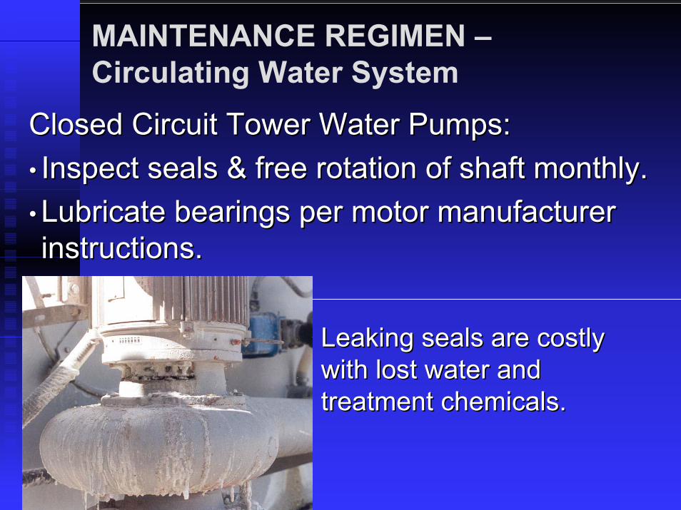
Closed Circuit Tower Water Pumps:Closed Circuit Tower Water Pumps:•• Inspect seals & free rotation of shaft monthly.Inspect seals & free rotation of shaft monthly.•• Lubricate bearings per motor manufacturer Lubricate bearings per motor manufacturer instructions.instructions.
Leaking seals are costly Leaking seals are costly with lost water and with lost water and treatment chemicals.treatment chemicals.
MAINTENANCE REGIMEN –Circulating Water System
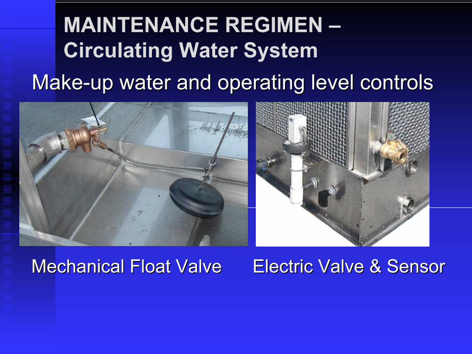
MakeMake--up water and operating level controlsup water and operating level controls
Mechanical Float Valve Electric Valve & SensorMechanical Float Valve Electric Valve & Sensor

MAINTENANCE REGIMEN –Circulating Water System
Set operating level and water supply pressure to Set operating level and water supply pressure to manufacturer’s recommendations.manufacturer’s recommendations.
••Inspect water level and adjust float monthly.Inspect water level and adjust float monthly.
••Inspect valve seals and full shutInspect valve seals and full shut--off monthly.off monthly.
Clean electronic sensing elements as required! Clean electronic sensing elements as required!

MAINTENANCE REGIMEN –Circulating Water System
Malfunctioning level Malfunctioning level control can be costly with control can be costly with water and chemical loss water and chemical loss and even equipment and even equipment damage.damage.
Proper water level control is required for pump Proper water level control is required for pump priming and prevention of air entrainment in priming and prevention of air entrainment in suction lines.suction lines.

MAINTENANCE REGIMEN –Fan & Drive System
The fan system moves the air which cools The fan system moves the air which cools the water. the water. It is critical to keep the fan It is critical to keep the fan system in top operating condition!system in top operating condition!
•• Daily walk around the tower and listen for unusual Daily walk around the tower and listen for unusual noises or vibration.noises or vibration.
•• If reasons for vibration are easily detected, (loose If reasons for vibration are easily detected, (loose belts, loose motor base, loose bearing locking belts, loose motor base, loose bearing locking collars, loose fan or sheave bushings) correct as collars, loose fan or sheave bushings) correct as required.required.
•• If causes of vibration are not easily detected, If causes of vibration are not easily detected, consult a specialty vibration analysis contractor.consult a specialty vibration analysis contractor.

MAINTENANCE REGIMEN –Fan & Drive System
•• Quarterly clean fan of heavy debris (trash, Quarterly clean fan of heavy debris (trash, bird droppings, scale) and inspect the fan bird droppings, scale) and inspect the fan and drive components for tight fasteners, and drive components for tight fasteners, missing balance washers & structural missing balance washers & structural integrity. integrity.
•• Repair or replace corroded hardware, Repair or replace corroded hardware, even the fan if necessary. even the fan if necessary.
•• Check the mechanical equipment support Check the mechanical equipment support for cracks and tight hardware.for cracks and tight hardware.
•• Check security of fan guards.Check security of fan guards.

MAINTENANCE REGIMEN –Fan & Drive System
Belt Drive Systems:Belt Drive Systems:Belt Tensioning:Belt Tensioning:Check 24 hrs after startCheck 24 hrs after start--up.up.
Check monthly thereafter.Check monthly thereafter.
1/2” 1/2” -- 3/4” deflection with 3/4” deflection with moderate finger pressure at moderate finger pressure at center span of belt. Check center span of belt. Check manufacturer’s O&M guide.manufacturer’s O&M guide.

MAINTENANCE REGIMEN –Fan & Drive System
Gear Drive Systems:Gear Drive Systems:Lubrication:Lubrication:Check oil level weekly.Check oil level weekly.Change oil 500 hours or Change oil 500 hours or 4 weeks after start4 weeks after start--up.up.Follow gear box O&M Follow gear box O&M guide for oil type and guide for oil type and change frequency. change frequency. Recommend synthetic, Recommend synthetic, oxidation inhibited oil.oxidation inhibited oil.

MAINTENANCE REGIMEN –Fan & Drive System
Gear Drive Systems:Gear Drive Systems: Drive Shafts:Drive Shafts:•• Inspect drive shaft Inspect drive shaft and coupling and coupling hardware monthly.hardware monthly.
•• Inspect coupling flex Inspect coupling flex elements for elements for buckling and fatigue buckling and fatigue damage. Replace damage. Replace as required.as required.
Drive shaft CouplingDrive shaft Coupling
MAINTENANCE REGIMEN –Fan & Drive System
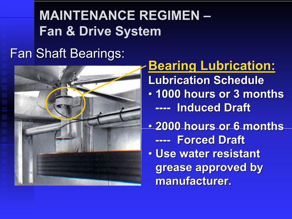
Fan Shaft Bearings:Fan Shaft Bearings:Bearing Lubrication:Bearing Lubrication:Lubrication ScheduleLubrication Schedule•• 1000 hours or 3 months 1000 hours or 3 months
-------- Induced DraftInduced Draft•• 2000 hours or 6 months 2000 hours or 6 months
-------- Forced DraftForced Draft•• Use water resistant Use water resistant
grease approved by grease approved by manufacturer.manufacturer.

MAINTENANCE REGIMEN –Fan & Drive System
Motors:Motors:Good maintenance starts with the installationGood maintenance starts with the installation1. Wire per nameplate and check rotation1. Wire per nameplate and check rotation•• MultiMulti--lead (9, 12 wire) motors may be confusinglead (9, 12 wire) motors may be confusing•• Check multiCheck multi--speed motor rotation at both speedsspeed motor rotation at both speeds•• Check current draw on startCheck current draw on start--upup2. 2. Check operational controlsCheck operational controls•• Set proper time delay between speed changesSet proper time delay between speed changes•• Set thermostat differentials to limit fan cycling Set thermostat differentials to limit fan cycling
(3(3--6 starts/hour)6 starts/hour)
MAINTENANCE REGIMEN –Fan & Drive System
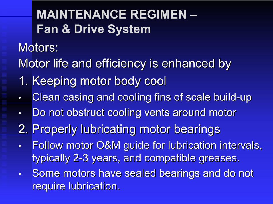
Motors:Motors:Motor life and efficiency is enhanced byMotor life and efficiency is enhanced by1. Keeping motor body cool1. Keeping motor body cool•• Clean casing and cooling fins of scale buildClean casing and cooling fins of scale build--upup•• Do not obstruct cooling vents around motorDo not obstruct cooling vents around motor2. Properly lubricating motor bearings2. Properly lubricating motor bearings•• Follow motor O&M guide for lubrication intervals, Follow motor O&M guide for lubrication intervals,
typically 2typically 2--3 years, and compatible greases.3 years, and compatible greases.•• Some motors have sealed bearings and do not Some motors have sealed bearings and do not
require lubrication.require lubrication.

MAINTENANCE REGIMEN –Fan & Drive System
Motors:Motors:Motors driven by variable frequency drives (Motors driven by variable frequency drives (vfdvfd) ) 1.1. Offer fan energy saving at the cooling towerOffer fan energy saving at the cooling tower2.2. Reduce fan cycling and provide soft startingReduce fan cycling and provide soft starting3.3. Need to be specifically selected for Need to be specifically selected for vfdvfd dutyduty4.4. Need limits on length between motor & driveNeed limits on length between motor & drive
(Depending on drive, typically 50 to 200 feet.)(Depending on drive, typically 50 to 200 feet.)5.5. Run hotter and need good cooling airRun hotter and need good cooling air--flowflow

MAINTENANCE REGIMEN –Heat Transfer Surface
Open tower surface (fill)Open tower surface (fill) Closed circuit tower coilClosed circuit tower coil
Inspect heat transfer surfaces monthly.Inspect heat transfer surfaces monthly.Inspect both the top Inspect both the top andand bottom. Generally, bottom. Generally, scaling starts on the top and bioscaling starts on the top and bio--fouling builds fouling builds from the bottom. from the bottom.

MAINTENANCE REGIMEN –Heat Transfer Surface
Open Tower Packing (Fill):Open Tower Packing (Fill):••Scale, solids and bioScale, solids and bio--fouling fouling restrict air & water passages.restrict air & water passages.
••Capacity diminishes rapidly Capacity diminishes rapidly with increased fouling.with increased fouling.
••Extra weight can damage fill Extra weight can damage fill and structural supports.and structural supports.
Typical fill clogging from bioTypical fill clogging from bio--films and suspended solids.films and suspended solids.

MAINTENANCE REGIMEN –Heat Transfer Surface
Closed Circuit Tower Coil:Closed Circuit Tower Coil:••Scale on coil Scale on coil walls is a direct walls is a direct heat transfer heat transfer barrier. barrier.
••Capacity Capacity diminishes with diminishes with increased increased fouling.fouling.

MAINTENANCE REGIMEN –Heat Transfer Surface
Closed Circuit Cooling Tower Performance vs. Scale Accumulation on Heat Transfer Coil
40.0%50.0%60.0%70.0%80.0%90.0%
100.0%
0 0.002 0.004 0.006
Fouling Factor & Approximate Scale Thickness On Coil
Tow
er P
erfo
rman
ce
Cap
abili
ty
1/32" Scale 1/16" ScaleClean Tube 3/32" Scale
High Heat Flux Coil
Low Heat Flux Coil
( 0.8 mm ) ( 1.6 mm ) ( 2.4 mm )
Closed Circuit Tower CoilClosed Circuit Tower Coil

MAINTENANCE REGIMEN –Heat Transfer Surface
Cleaning heavy scale or bioCleaning heavy scale or bio--fouling is difficult.fouling is difficult.Often the fill or coil are damaged in the process.Often the fill or coil are damaged in the process.
Results of a scaled coilResults of a scaled coilcleaned with acid. cleaned with acid. This coil is ruined.This coil is ruined.
IT IS ESSENTIAL TO MAINTAIN A IT IS ESSENTIAL TO MAINTAIN A PREVENTATIVEPREVENTATIVE WATER TREATMENT WATER TREATMENT PROGRAM.PROGRAM.

MAINTENANCE REGIMEN –Drift Eliminators
Separate water droplets from leaving air streamSeparate water droplets from leaving air stream••Subject to damage from weather & vandalismSubject to damage from weather & vandalism••Subject to corrosionSubject to corrosion
Damaged eliminatorDamaged eliminatorsection, which shouldsection, which shouldbe replaced.be replaced.

MAINTENANCE REGIMEN –Drift Eliminators
Proper placement and good physical conditionProper placement and good physical condition•• Minimizes water and treatment chemical lossMinimizes water and treatment chemical loss•• Minimizes air restriction for maximum capacityMinimizes air restriction for maximum capacity•• Minimizes airborne bacterial transmission Minimizes airborne bacterial transmission
Inspect condition and placement monthly.Inspect condition and placement monthly.Remove bioRemove bio--growth and debris. Notify growth and debris. Notify treatment service of biotreatment service of bio--growth. growth. Replace damaged eliminators.Replace damaged eliminators.

MAINTENANCE REGIMEN –Air Inlet Louvers
Examples of scaled, bioExamples of scaled, bio--fouled and debris laden inlet louvers.fouled and debris laden inlet louvers.

MAINTENANCE REGIMEN –Air Inlet Louvers
Proper placement and good physical conditionProper placement and good physical condition•• Minimizes water and treatment chemical loss Minimizes water and treatment chemical loss
from basin splashfrom basin splash--out.out.•• Minimizes air restriction for maximum capacityMinimizes air restriction for maximum capacity•• Minimizes airborne bacterial transmission Minimizes airborne bacterial transmission
Inspect condition and placement monthly.Inspect condition and placement monthly.Remove bioRemove bio--growth and debris. Notify growth and debris. Notify treatment service of biotreatment service of bio--growth. growth. Repair damaged louvers.Repair damaged louvers.

Winter OperationMaintenance & Energy Saving Tips
Prevent freezing and expensive ice damage Prevent freezing and expensive ice damage before the winter season arrives:before the winter season arrives:
•• Check heat tracing and insulation on drains, Check heat tracing and insulation on drains, makemake--up and circulating water lines.up and circulating water lines.
•• Test basin heaters and controls.Test basin heaters and controls.•• Charge coils with glycol or drain completely.Charge coils with glycol or drain completely.•• Test operation of positive closure dampers Test operation of positive closure dampers --
open with fan on and closed with fan off. open with fan on and closed with fan off.

Winter OperationMaintenance & Energy Saving Tips
More tips:More tips:•• Do not run fans with pumps off unless basin is Do not run fans with pumps off unless basin is
drained.drained.•• Ensure that fan drives are selected for dry Ensure that fan drives are selected for dry
operation.operation.•• Interlock heater “off” when pump or fan Interlock heater “off” when pump or fan
operates.operates.•• Keep a heat load on the tower. Cold water Keep a heat load on the tower. Cold water
temperature should stay above 40°F (4.4C) temperature should stay above 40°F (4.4C)

Winter OperationMaintenance & Energy Saving Tips
Ice can cause expensive damage to the fill and Ice can cause expensive damage to the fill and tower structure.tower structure.
•• Schedule regular Schedule regular defrost cycles.defrost cycles.
•• Keep water flow in Keep water flow in safe range of the safe range of the distribution nozzle.distribution nozzle.

Maintenance & Energy Efficient OperationTowers lacking a good maintenance regimen, which Towers lacking a good maintenance regimen, which includes water treatment, routinely operate at well below includes water treatment, routinely operate at well below design capability.design capability.
A basic maintenance regimen is an investment to: A basic maintenance regimen is an investment to: maximize the energy efficiency of the tower and maximize the energy efficiency of the tower and the mechanical system,the mechanical system,minimize capital investment in equipment by minimize capital investment in equipment by extending its life and replacement intervals,extending its life and replacement intervals,minimize annual maintenance expenses through minimize annual maintenance expenses through preventative measures rather than costly repairs.preventative measures rather than costly repairs.
Cooling Tower Operation and Maintenance for Improved Energy Efficiency
Operating Strategies and Water Treatment
Paul Lindahl

WHY WATER TREATMENT? Air
Water
AirDebrisGases
Air and water contents enter and build in the tower.

Biological Growth
Bacteria, AlgaeBacteria, AlgaeFouling exchangersFouling exchangersFouling Cooling TowerFouling Cooling TowerHealth Effects, such as Legionnaire’s DiseaseHealth Effects, such as Legionnaire’s Disease
Water TreatmentsWater TreatmentsOxidizing BiocidesOxidizing BiocidesNonNon--oxidizing Biocidesoxidizing Biocides
Deposits assist growth of Deposits assist growth of biofilms biofilms and and biofoulingbiofouling, , side stream filtration is recommendedside stream filtration is recommended

Corrosion
Consider metals in entire water systemConsider metals in entire water systemSteel and Iron vs. Stainless SteelSteel and Iron vs. Stainless SteelCopper and its AlloysCopper and its AlloysAluminumAluminum
Appropriate Water Treatments with Appropriate Water Treatments with qualified WT vendor/consultantqualified WT vendor/consultantControl deposition of solids, side stream Control deposition of solids, side stream filtration recommendedfiltration recommended
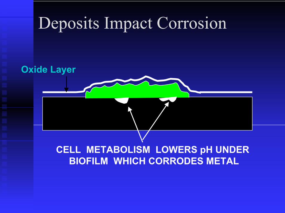
Deposits Impact Corrosion
Oxide Layer
CELL METABOLISM LOWERS pH UNDER BIOFILM WHICH CORRODES METAL

Deposits Impact Corrosion
Oxide Layer
PITTING FAILURE

Each Treatment Impacts the Others
MICROBES (MB)
CORROSION DEPOSITION

Control Methods
BiocideBiocide to reduce Microbe and to reduce Microbe and BiofilmBiofilmGrowth [corrosion and scaling effect]Growth [corrosion and scaling effect]InhibitorsInhibitors to protect Metals from Corrosionto protect Metals from CorrosionInhibitorsInhibitors to prevent Scale Precipitationto prevent Scale Precipitation
SurfactantSurfactant = Bio= Bio--penetrationpenetrationAntiAnti--foamfoam = Reduce visible effect of = Reduce visible effect of biocidebiocide

Water Quality
General GuidelinesGeneral Guidelines: : Note: for tower water, not makeNote: for tower water, not make--upup
High TemperatureHigh Temperature:: < 120 < 120 °°F F PH: 6.5 PH: 6.5 –– 9.09.0Chlorides: < 750 Chlorides: < 750 ppm ppm for Galvanized Steel, for Galvanized Steel, < 1500< 1500 ppmppm for 300 Series Stainless Steelfor 300 Series Stainless SteelCalcium: (as CaCO3) < 800Calcium: (as CaCO3) < 800 ppmppm should not should not result in calcium sulfate scaleresult in calcium sulfate scale

Water Quality
Sulfates: If calcium > 800Sulfates: If calcium > 800 ppmppm, sulfates < , sulfates < 800800 ppmppm (or less in arid climates) to limit (or less in arid climates) to limit scale. scale.
Otherwise, < 5000Otherwise, < 5000 ppmppm is acceptable. is acceptable. Silica: < 150Silica: < 150 ppmppm as SiO2 to prevent silica as SiO2 to prevent silica scalescaleIron: < 3 Iron: < 3 ppmppmManganese: < 0.1Manganese: < 0.1 ppmppm

Water Quality
Total Suspended Solids (TSS): Total Suspended Solids (TSS): < 25< 25 ppmppm for film fillfor film fill
Total Dissolved Solids (TDS): Total Dissolved Solids (TDS): < 5000< 5000 ppmppm for thermal performancefor thermal performance
Oil and Grease: Oil and Grease: Avoid with film fill (contributes to fill Avoid with film fill (contributes to fill plugging, prevents proper seasoning).plugging, prevents proper seasoning).
Ammonia: Ammonia: Limit to 50Limit to 50 ppmppm if copper alloys are presentif copper alloys are present

Water Quality
Combinations of treatment chemicals may Combinations of treatment chemicals may cause reactions which reduce treatment cause reactions which reduce treatment effectivenesseffectivenessCertain chemicals such as surfactants,Certain chemicals such as surfactants,biodispersantsbiodispersants and antifoams may increase and antifoams may increase drift ratedrift rateConsult CT & WT vendors/consultantsConsult CT & WT vendors/consultants

Concentrations and Blowdown
Evaporating water leaves minerals, Evaporating water leaves minerals, concentrates over timeconcentrates over timeBlowdown of a small amount of water Blowdown of a small amount of water keeps concentration at desired levelkeeps concentration at desired levelC = (R x EPD + BD + D)/(BD + D)C = (R x EPD + BD + D)/(BD + D)

Concentrations and Blowdown
Example:Example:Evaporation = 0.08% circulating water Evaporation = 0.08% circulating water per degree of rangeper degree of rangeDrift = 0.02% of circulating water rateDrift = 0.02% of circulating water rateRange = 10 Deg FRange = 10 Deg FConcentrations = 5Concentrations = 5Blowdown = 0.18% of circulating water Blowdown = 0.18% of circulating water raterate

Concentrations and Blowdown
Range 1.5 2 2.5 3 4 5 65 0.78 0.36 0.23 0.21 0.11 0.08 0.0610 1.58 0.76 0.50 0.41 0.24 0.18 0.1415 2.38 1.16 0.77 0.61 0.37 0.28 0.2220 3.18 1.56 1.03 0.81 0.51 0.38 0.3025 3.98 1.96 1.30 1.01 0.64 0.48 0.3830 4.78 2.36 1.57 1.21 0.77 0.58 0.4635 5.58 2.76 1.83 1.41 0.91 0.68 0.54
Based on: 0.02 % drift rate and 0.08 % evaporation rate

Operation for System Efficiency

Condensing Water Temperature
•• 3 GPM/TR (95°/85°/78°)3 GPM/TR (95°/85°/78°)•• 2 GPM/TR (105°/85°/78°)2 GPM/TR (105°/85°/78°)•• Lower condensing Lower condensing
temperatures, fans full, temperatures, fans full, gives coldest water at gives coldest water at chillerchiller
•• Chiller energy savings Chiller energy savings almost always outweighs almost always outweighs tower fan energy tower fan energy consumption
0.0350.04
0.0450.05
0.0550.06
0.0650.07
0.0750.08
0.085
80 81 82 83 84 85 86 87
3 GPM/TON 2 GPM/TON
DESIGN COLD WATER TEMP. — (°F)
HP
per
TON
DESIGN COOLING TOWER FAN HP VARIATIONFAN HP PER TON OF LOAD
(BASIS: 75°F WET-BULB)
consumption

Capacity Control Methodologies
•• Capacity Control DampersCapacity Control Dampers•• MultiMulti--speed Motorsspeed Motors•• Variable Frequency DrivesVariable Frequency Drives•• Single Speed Fan CyclingSingle Speed Fan Cycling•• Free CoolingFree Cooling•• Fans full Speed Fans full Speed –– Run Wild Run Wild

Capacity Control Dampers
•• Offers precise system controlOffers precise system control•• No fan power savingsNo fan power savings

Effect of Fan Speed on Capacity
0
20
40
60
80
100
0 10 20 30 40 50 60 70 80 90 100
CAPACITY (AIRFLOW) REQUIRED POWER
PERCENT OF DESIGN FAN SPEED
PERCENT
FAN CHARACTERISTICSCAPACITY & HORSEPOWER RELATIVE TO SPEED

Single Speed, Full Power
45505560657075808590
20 30 40 50 60 70 80
10°F RANGE
WET BULB TEMPERATURE — (°F)
COLD
WATER
TYPICAL COOLING TOWER PERFORMANCESINGLE CELL TOWER — SINGLE SPEED FAN

Two Speed
45505560657075808590
20 30 40 50 60 70 80
FULL SPEED HALF SPEED
WET BULB TEMPERATURE — (°F)
COLD
WATER
TYPICAL COOLING TOWER PERFORMANCESINGLE CELL TOWER — TWO SPEED FAN
(10°F RANGE)
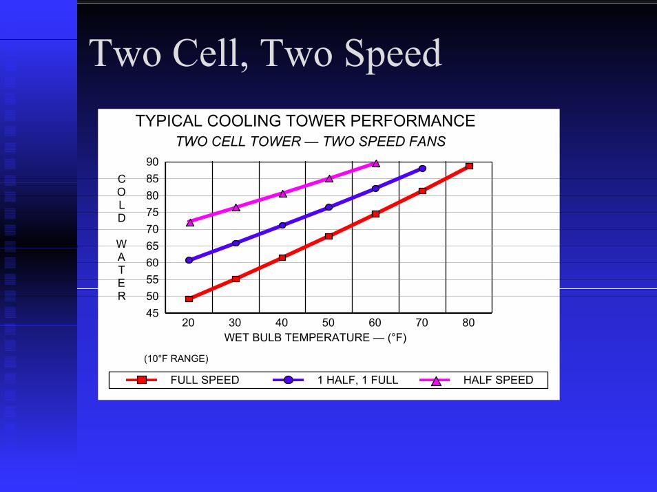
Two Cell, Two Speed
45505560657075808590
20 30 40 50 60 70 80
FULL SPEED 1 HALF, 1 FULL HALF SPEED
WET BULB TEMPERATURE — (°F)
COLD
WATER
TYPICAL COOLING TOWER PERFORMANCETWO CELL TOWER — TWO SPEED FANS
(10°F RANGE)

35° 45° 55° 65° 75° 85°
80%
60%
40%
20%
0
90°
80°
Cold Water °F
100%
100%
Control Temperature
Variable FrequencyDrive Fan
Control
Variable Frequency

Compressor Impact
45505560657075808590
20 30 40 50 60 70 80
10°F RANGE
WET BULB TEMPERATURE — (°F)
COLD
WATER
TYPICAL COOLING TOWER PERFORMANCESINGLE CELL TOWER — SINGLE SPEED FAN
Region for influencing compressor horsepower.

Compressor Power
8486889092949698
100
70 75 80 85
COMPRESSOR HORSEPOWER
COLD WATER TEMPERATURE (°F)
PERCENT
POTENTIAL COMPRESSOR HP REDUCTIONSCONSTANT LOAD — REDUCING CONDENSER WATER TEMPERATURE
This is a “rule of thumb” curve. Verify actual reductions with chiller manufacturer.

Free Cooling Region
45505560657075808590
20 30 40 50 60 70 80
10°F RANGE
WET BULB TEMPERATURE — (°F)
COLD
WATER
TYPICAL COOLING TOWER PERFORMANCESINGLE CELL TOWER — SINGLE SPEED FAN
Region for consideration of “free cooling”.

“Free Cooling”“Free Cooling”••When the tower can produce sufficiently When the tower can produce sufficiently cold water without the chiller.cold water without the chiller.
••Direct free cooling..Direct free cooling..
••Indirect free cooling..Indirect free cooling..

Free Cooling Operation
Graph assumes that the system will go to free cooling when the tower is capable of producing 50°F or colder water.
4045505560657075808590
20 30 40 50 60 70 80
CHILLER ON CHILLER OFF
WET BULB TEMPERATURE — (°F)
COLD
WATER
TYPICAL COOLING TOWER PERFORMANCEFULL LOAD — FULL FAN SPEED — FULL WATER FLOW

Benefit Depends on Location
0
2000
4000
6000
8000
10000
-10 0 10 20 30 40 50 60 70 80
ANNUAL HOURS INDICATED W.B. WILL NOT BE EXCEEDED
WET BULB TEMPERATURE — (°F)
HOURS
WET BULB OCCURRANCEDES MOINES VICINITY
Cooling Tower Operation and Maintenance for Improved Energy Efficiency