operation & maintenance instruction manual 03-06-2020
TRANSCRIPT

Operation & Maintenance Instruction Manual 03-06-2020

Toll Free: (800) 253-4252
200 N. Gooding Street – P.O. Box 160 Belding, MI 48809-0160
OPERATION & MAINTENANCE INSTRUCTIONS
P a g e | 1
(616) 794-1130 (616) 794-3666
[email protected] www.beldingtank.com
TABLE OF CONTENTS
GENERAL Page 2
TANKS FOR FOOD APPLICATION Page 2
AFTER THE TANK IS PUT INTO SERVICE Page 3
TANK USAGE Page 3
AIR LOADING Page 4
TOP MANWAY BOLTING (20” & 24”) Page 5
TOP MANWAY BOLTING (30” & 36”) Page 6
SIDE MANWAY BOLTING (20” thru 36” Current) Page 7
SIDE MANWAY BOLTING (20” & 24”) Page 8
SIDE MANWAY BOLTING (30” & 36”) Page 9
FLANGE BOLTING (1” – 14”) Page 10
FLANGE BOLTING (16” – 24”) Page 11
TORQUE INCREMENTS (LEGACY CROSS-PATTERN) Page 12
FLANGE ALLOWABLE LOADS Page 13

Toll Free: (800) 253-4252
200 N. Gooding Street – P.O. Box 160 Belding, MI 48809-0160
OPERATION & MAINTENANCE INSTRUCTIONS
P a g e | 2
(616) 794-1130 (616) 794-3666
[email protected] www.beldingtank.com
GENERAL Because of FIBERGLASS REINFORCED PLASTIC tanks unique, physical and structural characteristics; they are flexible, lightweight, corrosion resistant, and stronger than tanks made of other plastic materials.
Care, however, should be taken to follow the Handling and Installation instructions.
If your fiberglass tank has been installed with insulation and a Heat Maintenance Unit, the wiring instructions are placed inside the control box.
If you have a BTT Dual-Tek™ double wall tank and your tank was supplied with BTT’s Leak Detection System and/or Desiccant Filter, please refer to the instructions supplied with those items.
Once the tank has been properly installed and placed in service, BTT recommends regular routine inspections as a part of your preventative maintenance program.
The care and operation of FRP vessels rely mostly on common sense. To maximize trouble free service, Belding Tank recommends the following:
1. Inspect your vessel thoroughly upon receipt. 2. Follow the Handling and Installation instruction. 3. Wash your vessel thoroughly w/detergent and rinse before putting in service (see FDA
Requirements) TANKS FOR FOOD APPLICATION BELDING TANK TECHNOLOGIES tanks will comply with U.S. Food, Drug and Cosmetic Act, as amended, and applicable FDA regulations (21 cfr 177.2420). These tanks may be used as components intended for repeated use in contact with food, subject to certain limitations described in that regulation.
BELDING TANK TECHNOLOGIES tanks are chemically acceptable in processing or storage areas for contact with meat or poultry food products prepared under federal inspection and used at temperatures below 180° F. This acceptance has been given by the United States Department of Agriculture. Prior to shipping your tank, B.T.T. applies a (4) hour heat cure followed by a water rinse to the tank interior.
Toll Free: (800) 253-4252
200 N. Gooding Street – P.O. Box 160 Belding, MI 48809-0160
OPERATION & MAINTENANCE INSTRUCTIONS
P a g e | 3
(616) 794-1130 (616) 794-3666
[email protected] www.beldingtank.com
TANKS FOR FOOD APPLICATION (Cont’d.) After installation and before your tank is put into service, attention to the following procedures is important to achieve FDA compliance:
1. After tank installation, steam-treat or steep tank with hot water for 8-16 hours at 160° – 180° F. This should remove all residual styrene from the laminate surface.
2. Wash the tank thoroughly with detergent and rinse it thoroughly. 3. Check state and local regulations for required compliance in addition to the above
recommendations.
AFTER THE TANK IS PUT IN SERVICE: 1. Keep the vessel clean.
a. It will remain more aesthetically pleasing. b. If the tank is ever damaged, it will be evident.
2. Make a visual tank inspection inside and outside the tank every 6-12 months. 3. If your tank has been supplied with a screen on your Vent, care should be taken to inspect the
screen regularly and kept clean and unobstructed. The screen will reduce the airflow. CAUTION: Condensate on the screen during cold weather may freeze which may result in damage to the tank. BTT recommends removing the screen during cold weather months.
4. Rapid temperature changes to the fiberglass tank MUST BE AVOIDED, especially going from a hot tank to a cold tank.
TANK USAGE This tank has been sold for a specific chemical storage application. Before changing the chemical environment, consult with BELDING TANK TECHNOLOGIES (your warranty may be void without written authorization from B.T.T.)
1. Do not allow the stored material to freeze. 2. BELDING TANK standard tanks are NOT designed for pressure or vacuum other than liquid
head. Do not restrict the tank vent. Vapor removal equipment (if installed) must not cause any pressure or vacuum conditions.
3. The rated capacity of the tank is to the top of the straight side only. If any of the above guidelines are not followed or if any modifications are made without written approval from BELDING TANK TECHNOLOGIES, it could result in structural damage to the tank and would void the existing warranty.

Toll Free: (800) 253-4252
200 N. Gooding Street – P.O. Box 160 Belding, MI 48809-0160
OPERATION & MAINTENANCE INSTRUCTIONS
P a g e | 4
(616) 794-1130 (616) 794-3666
[email protected] www.beldingtank.com
AIR LOADING “Tanks are often filled with liquids from tanker trucks by pressurizing the headspace above the liquid within the tanker with compressed air to force tanker contents into the receiving tank. This is most typically done when the liquid being transferred is a corrosive chemical, which could damage a pump. Although such a procedure eliminates the need for a pump, a possibility does exist that the pressurized air within the tanker will follow the liquid into the receiving tank, and destroy the tank, due to excessive pressure.
Generally speaking, the tanker is connected to the receiving tank by a hose. The compressed air pushing down on the liquid forces the liquid through the hose and into the receiving tank. The frictional resistance offered by the hose and the fitting limits the maximum velocity of the liquid moving through the hose to a reasonable value. The air displaced by the liquid entering the tank escapes through the normal vent provided on the tank.
However, when the last of the liquid passes through the hose, the compressed air within the tanker rushes through the hose at an extremely high velocity, because this air does not meet significant frictional resistance in the hose, as the liquid does. This air enters the headspace in the receiving tank and expands with almost explosive speed and force. The conventional tank vent cannot relieve this excessive pressure within the tank. When the pressure within the receiving tank exceeds that for which the tank is designed, either the tank head blows off or some other portion of the tank ruptures.
Preferably, the person operating the tanker will interrupt the liquid flow before the last of the liquid leaves the tanker, preventing the compressed air from entering the tank. However, through inattention or carelessness, the operator will occasionally forget to interrupt the liquid at the "appropriate time"…RESULT…POSSIBLE TANK FAILURE.”
The quoted description above is the possible occurrence when the tank is air loaded…IMPROPERLY; proper procedure requires that the operator interrupt the liquid at the appropriate time. PROPER PROCEDURE WILL NOT CAUSE TANK FAILURE.
To guard against tank failure when the tank is air loaded, opening the manway cover is suggested. This precaution, if the tank is air loaded improperly, does NOT eliminate the possibility of tank failure…but it may lessen the possibility. TO ELIMINATE TANK FAILURE DUE TO IMPROPER AIR LOADING:
A. BUILD A PRESSURE VESSEL, OR B. ELIMINATE THE POSSIBILITY OF THE AIR PAD PRESSURE IN THE TANKER FROM REACHING THE
TANK INTERIOR BY: 1. Suspending the fill line above the manway (i.e. line is not to enter tank), OR… 2. Monitoring a flow meter to determine when the tanker will be empty, OR… 3. Install a "No-Flow" switch in tandem with a control valve.
Note: B.T.T. recommends consulting with a reputable firm in reference to flow meters and no flow switches.
If you have any questions or special circumstances that require discussion, please feel free to contact us at… 1-800-253-4252.

Toll Free: (800) 253-4252
200 N. Gooding Street – P.O. Box 160 Belding, MI 48809-0160
OPERATION & MAINTENANCE INSTRUCTIONS
P a g e | 5
(616) 794-1130 (616) 794-3666
[email protected] www.beldingtank.com
TOP MANWAY BOLTING SEQUENCE
20” Top Manway 24” Top Manway
Drawings not to scale
BELDING TANK TECHNOLOGIES standard ATMOSPHERIC pressure top manway includes half the number of bolts as shown in the illustrations above. The bolts should be hand tightened plus a 1/8 turn. The bolt sequence above does NOT have to be followed.
When the tank is designed for pressure up to 12” water column (0.432 psig), then ALL bolts illustrated above will be included and the bolt torque setting is 3 ft. lbs.
For pressures above 12” water column (0.432 psig), please refer to the side manway bolt sequence and torque charts for rated pressure.

Toll Free: (800) 253-4252
200 N. Gooding Street – P.O. Box 160 Belding, MI 48809-0160
OPERATION & MAINTENANCE INSTRUCTIONS
P a g e | 6
(616) 794-1130 (616) 794-3666
[email protected] www.beldingtank.com
TOP MANWAY BOLTING SEQUENCE
30” Top Manway 36” Top Manway
Drawings not to scale
BELDING TANK TECHNOLOGIES standard ATMOSPHERIC pressure top manway includes half the number of bolts as shown in the illustrations above. The bolts should be hand tightened plus a 1/8 turn. The bolt sequence above does NOT have to be followed.
When the tank is designed for pressure up to 12” water column (0.432 psig), then ALL bolts illustrated above will be included and the bolt torque setting is 3 ft. lbs.
For pressures above 12” water column (0.432 psig), please refer to the side manway bolt sequence and torque charts for rated pressure.

Toll Free: (800) 253-4252
200 N. Gooding Street – P.O. Box 160 Belding, MI 48809-0160
OPERATION & MAINTENANCE INSTRUCTIONS
P a g e | 7
(616) 794-1130 (616) 794-3666
[email protected] www.beldingtank.com
SIDE MANWAY BOLTING SEQUENCE
(BUILT 12-11-17 TO PRESENT)
20” & 24” Side Manway 30” Side Manway 36” Side Manway
Drawings not to scale
Side Manway Maximum Bolt Torque
Manway PSI Rating (See Drawing Attachment Chart)
Diameter 10 15 20 25 30 40 50
20” 14 ft. lbs. 14 ft. lbs. 28 ft. lbs. 28 ft. lbs. 28 ft. lbs. 38 ft. lbs. 46 ft. lbs.
24” 14 ft. lbs. 27 ft. lbs. 27 ft. lbs. 40 ft. lbs. 40 ft. lbs. 53 ft. lbs. 65 ft. lbs.
30” 36 ft. lbs. 36 ft. lbs. 36 ft. lbs. 36 ft. lbs. 43 ft. lbs. 56 ft. lbs. 69 ft. lbs.
36” 26 ft. lbs. 39 ft. lbs. 51 ft. lbs. 63 ft. lbs. 75 ft. lbs. 99 ft. lbs. 121 ft. lbs.

Toll Free: (800) 253-4252
200 N. Gooding Street – P.O. Box 160 Belding, MI 48809-0160
OPERATION & MAINTENANCE INSTRUCTIONS
P a g e | 8
(616) 794-1130 (616) 794-3666
[email protected] www.beldingtank.com
SIDE MANWAY BOLTING SEQUENCE (BUILT PRIOR TO 12-11-17)
20” Side Manway 24” Side Manway
Drawings not to scale
Side Manway Maximum Bolt Torque
Manway PSI Rating (See Drawing Attachment Chart)
Diameter 5 10 15 20 25 30 35 40
20” 16 ft. lbs. 20 ft. lbs. 20 ft. lbs. 20 ft. lbs. 20 ft. lbs. 20 ft. lbs. 20 ft. lbs. 20 ft. lbs.
24” 16 ft. lbs. 20 ft. lbs. 20 ft. lbs. 20 ft. lbs. 20 ft. lbs. 20 ft. lbs. 20 ft. lbs. 20 ft. lbs.

Toll Free: (800) 253-4252
200 N. Gooding Street – P.O. Box 160 Belding, MI 48809-0160
OPERATION & MAINTENANCE INSTRUCTIONS
P a g e | 9
(616) 794-1130 (616) 794-3666
[email protected] www.beldingtank.com
SIDE MANWAY BOLTING SEQUENCE (BUILT PRIOR TO 12-11-17)
30” Side Manway 36” Side Manway
Drawings not to scale
Side Manway Maximum Bolt Torque
Manway PSI Rating (See Drawing Attachment Chart)
Diameter 5 10 15 20 25 30 35 40
30” 25 ft. lbs. 43 ft. lbs. 43 ft. lbs. 43 ft. lbs. 43 ft. lbs. 43 ft. lbs. 43 ft. lbs. 43 ft. lbs.
36” 25 ft. lbs. 43 ft. lbs. 43 ft. lbs. 43 ft. lbs. 43 ft. lbs. 43 ft. lbs. 43 ft. lbs. 43 ft. lbs.

Toll Free: (800) 253-4252
200 N. Gooding Street – P.O. Box 160 Belding, MI 48809-0160
OPERATION & MAINTENANCE INSTRUCTIONS
P a g e | 10
(616) 794-1130 (616) 794-3666
[email protected] www.beldingtank.com
FLANGED NOZZLE BOLTING SEQUENCE
CAUTION: A flange spacer MUST BE USED when bolting FRP flanges to raised face flanges. Use only full-face gaskets. Do NOT over torque flange bolts.
4 Bolt 8 Bolt 12 Bolt
Drawings not to scale
Flanged Nozzle PSI Rating & Maximum Torque
Diameter PSI Rating Maximum Torque
1” 150 12 ft. lbs.
1-1/2” 150 14 ft. lbs.
2” 150 22 ft. lbs.
2-1/2” 150 24 ft. lbs.
3” 150 36 ft. lbs.
4” 150 24 ft. lbs.
6” 100 34 ft. lbs.
8” 50 28 ft. lbs.
10” 50 29 ft. lbs.
12” 50 43 ft. lbs.
14” 50 55 ft. lbs.

Toll Free: (800) 253-4252
200 N. Gooding Street – P.O. Box 160 Belding, MI 48809-0160
OPERATION & MAINTENANCE INSTRUCTIONS
P a g e | 11
(616) 794-1130 (616) 794-3666
[email protected] www.beldingtank.com
FLANGED NOZZLE BOLTING SEQUENCE
CAUTION: A flange spacer MUST BE USED when bolting FRP flanges to raised face flanges. Use only full-face gaskets. Do NOT over torque flange bolts.
16 Bolt 20 Bolt
Drawings not to scale
Flanged Nozzle PSI Rating & Maximum Torque
Diameter PSI Rating Maximum Torque
16” 50 54 ft. lbs.
18” 50 88 ft. lbs.
20” 50 85 ft. lbs.
24” 50 116 ft. lbs.

Toll Free: (800) 253-4252
200 N. Gooding Street – P.O. Box 160 Belding, MI 48809-0160
OPERATION & MAINTENANCE INSTRUCTIONS
P a g e | 12
(616) 794-1130 (616) 794-3666
[email protected] www.beldingtank.com
Torque Increments for Legacy Cross-Pattern Tightening
(DO NOT OVER TORQUE THE BOLTS)
Step 1: Make sure ALL threads are properly lubricated.
Step 2: Hand tighten all bolts. Check flange gap around circumference for uniformity. If the gap around the circumference is not reasonably uniform, make the appropriate adjustments by selective tightening before proceeding.
Step 3: Tighten to 20% to 25% of Maximum Torque. Check flange gap around circumference for uniformity. If the gap around the circumference is not reasonably uniform, make the appropriate adjustments by selective tightening before proceeding.
Step 4: Tighten to 45% to 50% of Maximum Torque. Check flange gap around circumference for uniformity. If the gap around the circumference is not reasonably uniform, make the appropriate adjustments by selective tightening before proceeding.
Step 5: Tighten to 100% of Maximum Torque. Check flange gap around circumference for uniformity. If the gap around the circumference is not reasonably uniform, make the appropriate adjustments by selective tightening before proceeding.
Step 6: It is possible that the gasket will relax after seating. Retightening is recommended 24 hours after installation to compensate for the relaxation. DO NOT over torque the bolts.
Toll Free: (800) 253-4252
200 N. Gooding Street – P.O. Box 160 Belding, MI 48809-0160
OPERATION & MAINTENANCE INSTRUCTIONS
P a g e | 13
(616) 794-1130 (616) 794-3666
[email protected] www.beldingtank.com
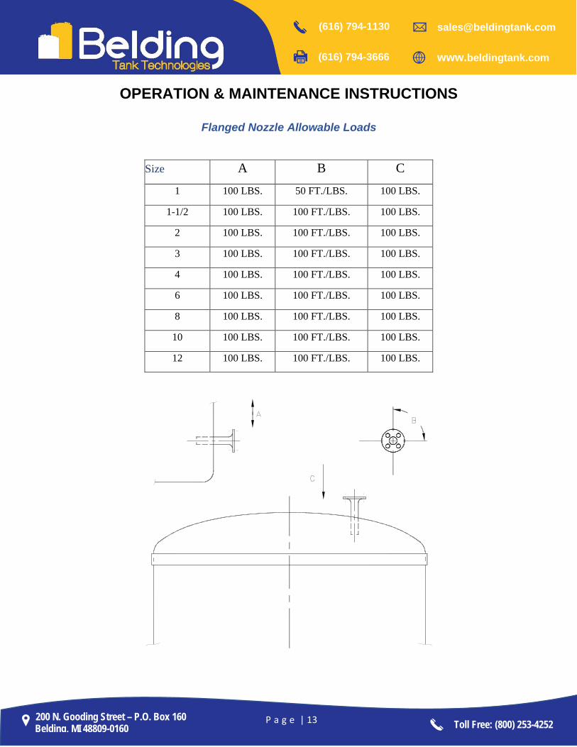
Flanged Nozzle Allowable Loads
Size A B C 1 100 LBS. 50 FT./LBS. 100 LBS.
1-1/2 100 LBS. 100 FT./LBS. 100 LBS.
2 100 LBS. 100 FT./LBS. 100 LBS.
3 100 LBS. 100 FT./LBS. 100 LBS.
4 100 LBS. 100 FT./LBS. 100 LBS.
6 100 LBS. 100 FT./LBS. 100 LBS.
8 100 LBS. 100 FT./LBS. 100 LBS.
10 100 LBS. 100 FT./LBS. 100 LBS.
12 100 LBS. 100 FT./LBS. 100 LBS.