operatinginstructions 1211.8/12-10 g2 · pdf fileoperatinginstructions 1211.8/12-10 g2 etanorm...
TRANSCRIPT

Operating Instructions1211.8/12-10 G2 Etanorm
Standardized pumps
Works No.: _____________________________________
Type series: Etanorm .
These operating instructions contain fundamentalinformation and precautionary notes. Please read
the manual thoroughly prior to installation of unit, electri-cal connection and commissioning. It is imperative to com-ply with all other operating instructions referring to compo-nents of individual units.
This manualshallalways be keptclose to the unit’slocation ofoperation ordirectly on the pump set.
www.bymisa.mx , Email [email protected]
Etanorm
2
Contents
Page
1 General 4
2 Safety 4
2.1 Marking of instructions in the manual 4
2.2 Personnel qualification and training 4
2.3 Non-compliance with safety instructions 4
2.4 Safety awareness 4
2.5 Safety instructions for the operator / user 4
2.6 Safety instructions for maintenance, inspec-tion and installation work 5
2.7 Unauthorized modification and manufactureof spare parts 5
2.8 Unauthorized modes of operation 5
3 Transport and interim storage 5
3.1 Transport 5
3.2 Interim storage/Preservation 5
4 Description of the product andaccessories 5
4.1 Technical specification 5
4.2 Designation 5
4.3 Design details 5
4.4 Permissible forces and moments at the pumpnozzles 6
4.5 Noise characteristics 7
4.6 Accessories 7
5 Installation at site 7
5.1 Safety regulations 7
5.2 Checks to be carried out prior to installation 7
5.3 Installing the pump/unit 7
5.3.1 Place of installation 7
5.3.2 Aligning the pump / drive 8
5.4 Connecting the piping 8
5.4.1 Vacuum balance line 9
5.4.2 Auxiliary connections 9
5.5 Connection to power supply 9
5.5.1 Connecting the motor/PTC resistors 9
5.5.2 Setting the time relay 10
5.5.3 Checking the direction of rotation 10
6 Commissioning, start-up / shutdown 10
6.1 Commissioning 10
6.1.1 Lubricants 10
6.1.2 Shaft seal 10
6.1.3 Priming thepumpandchecks tobecarriedout 10
6.1.4 Final check 10
6.1.5 Guard 10
Page
6.1.6 Start-up 10
6.1.7 Shutdown 10
6.2 Operating limits 10
6.2.1 Temperature of the medium handled 10
6.2.2 Switching frequency 11
6.2.3 Minimum flow 11
6.2.4 Density of medium handled 11
6.3 Shutdown / Storage / Preservation 11
6.3.1 Storage of new pumps 11
6.3.2 Measures to be taken for prolongedshutdown 11
6.4 Returning to service after storage 11
7 Servicing / Maintenance 11
7.1 General instructions 11
7.2 Servicing / inspection 11
7.2.1 Supervision of operation 11
7.2.2 Lubrication and lubricant change 12
7.3 Drainage / disposal 12
7.4 Dismantling 12
7.4.1 Fundamental instructions and recommen-dations
12
7.4.2 Preparations for dismantling 13
7.4.3 Pump 13
7.4.4 Mechanical seal 13
7.5 Reassembly 13
7.5.1 Pump 13
7.5.2 Shaft seal 13/14
7.5.3 Tightening torques 15
7.6 Spare parts stock 16
7.6.1 Ordering spare parts 16
7.6.2 Recommended spare parts stock for 2 years’operation
16
7.6.3 Interchangeability of pump components 17
8 Trouble-shooting 18
9 Related documents 19-23
9.1 Explodedview /ListofcomponentsPumpwithmechanicalsealandbolted-ondischargecover 19
9.2 Explodedview /ListofcomponentsPumpwithmechanicalsealandclampeddischargecover 20
9.3 Explodedview /ListofcomponentsPumpwithglandpackingandbolted-ondischargecover 21
9.4 Explodedview /ListofcomponentsPumpwithglandpackingandclampeddischargecover1 22
9.5 Exploded view / List of component: Etanormwith constant-level oiler 23
www.bymisa.mx , Email [email protected]

Etanorm
3
Index
Section Page
Technical specification 4.1 5
General instructions 7.1 11
General 1 4
Connecting the piping 5.4 8
Priming the pump and checks to becarried out 6.1.3 10
Installing the pump/unit 5.3 7
Installation at site 5 7
Place of installation 5.3.1 7
Aligning the pump / drive 5.3.2 8
Shutdown 6.1.7 10
Shutdown / Storage / Preservation 6.3 11
Interchangeability of pump components 7.6.3 17
Designation 4.2 5
Guard 6.1.5 10
Description of the product and accessories 4 5
Supervision of operation 7.2.1 11
Dismantling 7.4 12
Preparations for dismantling 7.4.2 13
Density of medium handled 6.2.4 11
Checking the direction of rotation 5.5.3 10
Unauthorized modification and manufactureof spare parts 2.7 5
Storage of new pumps 6.3.1 11
Start-up 6.1.6 10
Setting the time relay 5.5.2 10
Connection to power supply 5.5 9
Recommended spare parts stock for2 years’ operation 7.6.2 16
Final check 6.1.4 10
Drainage / disposal 7.3 12
Ordering spare parts 7.6.1 16
Spare parts stock 7.6 16
Commissioning 6.1 10
Exploded view / List of components Etanormwith constant-level oiler 9.5 23
Exploded view / List of components:Pump with mechanical seal andbolted-on discharge cover 9.1 19
Exploded view / List of components:Pump with mechanical seal and clampeddischarge cover 9.2 20
Exploded view / List of components:Pump with gland packing and bolted-ondischarge cover 9.3 21
Exploded view / List of components:Pump with gland packing and clampeddischarge cover 9.4 22
Non-compliance with safety instructions 2.3 4
Noise characteristics 4.5 7
Mechanical seal 7.4.4 13
Operating limits 6.2 10
Fundamental instructions and recommenda-tions
7.4.1 12
Section Page
Commissioning, start-up / shutdown 6 10
Marking of instructions in the manual 2.1 4
Design details 4.3 5
Measures tobe taken forprolongedshutdown 6.3.2 11
Minimum flow 6.2.3 11
Connecting the motor/PTC resistors 5.5.1 9
Personnel qualification and training 2.2 4
Pump 7.4.3/7.5.1 13
Switching frequency 6.2.2 11
Lubricants 6.1.1 10
Lubrication and lubricant change 7.2.2 12
Tightening torques 7.5.3 15
Safety 2 4
Safety regulations 5.1 7
Safety awareness 2.4 4
Safety instructions for the operator / user 2.5 4
Safety instructions for maintenance, inspec-tion and installation work 2.6 5
Trouble-shooting 8 18
Temperature of medium handled 6.2.1 10
Transport and interim storage 3 5
Transport 3.1 5
Checks to be carried out prior to installation 5.2 7
Unauthorized modes of operation 2.8 5
Vacuum balance line 5.4.1 9
Servicing / inspection 7.2 11
Servicing / Maintenance 7 11
Shaft seal 6.1.2/7.5.2 10/13
Returning to service after storage 6.4 11
Reassembly 7.5 13
Accessories 4.6 7
Related documents 9 19-23
Permissible forces and moments at thepump nozzles 4.4 6
Auxiliary connections 5.4.2 9
Interim storage/Preservation 3.2 5
www.bymisa.mx , Email [email protected]

Caution
Caution
Etanorm
4
1 GeneralThis KSB product has been developed in accord-ance with state-of-the-art technology; it is manu-
facturedwith utmost care and subject to continuous quality con-trol.These operating instructions are intended to facilitate familiariz-ation with the unit and its designated use.The manual contains important information for reliable, properand efficient operation. Compliance with the operating instruc-tions is of vital importance to ensure reliability anda longservicelife of the unit and to avoid any risks.These operating instructions do not take into account local re-gulations; the operator must ensure that such regulations arestrictly observed by all, including the personnel called in for in-stallation.
This pump / unit must not be operated beyond the limitvalues for themedium handled, capacity, speed, density,
pressure, temperature and motor rating specified in the techni-cal documentation. Make sure that operation is in accordancewith the instructions laid down in this manual or in the contractdocumentation. Contact the manufacturer, if required.The name plate indicates the type series / size, main operatingdata and works number; please quote this information in allqueries, repeat orders and particularly when ordering spareparts. If you need any additional information or instructions ex-ceeding the scope of this manual or in case of damage pleasecontact KSB’s nearest customer service centre.Noise characteristics see section 4.5.
2 SafetyThese operating instructions contain fundamental informationwhich must be complied with during installation, operation andmaintenance. Therefore this operating manual must be readand understood both by the installing personnel and the re-sponsible trained personnel / operators prior to installation andcommissioning, and it must always be kept close to the locationof operation of the machine / unit for easy access.Not only must the general safety instructions laid down in thischapter on ”Safety” be complied with, but also the safety in-structions outlined under specific headings.
2.1 Marking of instructions in the manual
The safety instructions contained in thismanual whose non-ob-servancemight cause hazards to persons are speciallymarkedwith the symbol
general hazard sign to ISO 7000-0434The electrical danger warning sign is
safety sign to IEC 417 - 5036,The word
is used to introduce safety instructions whose non-observancemay lead to damage to the machine and its functions.
Instructions attached directly to the machine, e.g.- arrow indicating the direction of rotation- markings for fluid connectionsmust always be complied with and be kept in a perfectly legiblecondition at all times.
2.2 Personnel qualification and training
All personnel involved in the operation, maintenance, inspec-tion and installation of the unitmust be fully qualified to carry outthe work involved.Personnel responsibilities, competence and supervision mustbe clearly defined by the operator. If the personnel in question isnot already in possession of the requisite know-how, appropri-ate training and instructionmust be provided. If required, theop-eratormay commission themanufacturer / supplier to take careof such training. In addition, the operator is responsible for en-suring that the contents of the operating instructions are fullyunderstood by the responsible personnel.
2.3 Non-compliance with safety instructions
Non-compliance with safety instructions can jeopardize thesafety of personnel, the environment and the machine / unit it-self. Non-compliance with these safety instructions will alsolead to forfeiture of any and all rights to claims for damages.
In particular, non-compliance can, for example, result in:
- failure of important unit functions,
- failure of prescribed maintenance and servicing practices,
- hazard to persons by electrical, mechanical and chemicaleffects,
- hazard to the environment due to leakage of hazardoussubstances.
2.4 Safety awareness
It is imperative to comply with the safety instructions containedin this manual, the relevant national health and safety regula-tions and the operator’s own internal work, operation and safetyregulations.
2.5 Safety instructions for the operator / user
- Any hot or cold components that could pose a hazard mustbe equipped with a guard by the operator.
- Guards which are fitted to prevent accidental contact withmoving parts (e.g. coupling) must not be removed whilstthe unit is operating.
- Leakages (e.g. at the shaft seal) of hazardous mediahandled (e.g. explosive, toxic, hot)must be contained soasto avoid any danger to persons or the environment. All rel-evant laws must be heeded.
- Electrical hazards must be eliminated. (In this respect referto the relevant safety regulations applicable to differentcountries and/or the local energy supply companies.)
www.bymisa.mx , Email [email protected]

1211:10/4
1211:144/2
Caution
Etanorm
5
2.6 Safety instructions for maintenance, inspectionand installation work
The operator is responsible for ensuring that all maintenance,inspection and installation work be performed by authorized,qualified specialist personnel who are thoroughly familiar withthe manual.The pump casing must have cooled down to ambient tempera-ture.Pump pressure must have been released and the pump musthave been drained.Work on the machine / unit must be carried out only duringstandstill. The shutdown procedure described in themanual fortaking the unit out of service must be adhered to without fail.Pumps or pump units handling media injurious to health mustbe decontaminated.Immediately following completion of the work, all safety-rel-evant and protective devices must be re-installed and / or re-activated.Please observe all instructions set out in the chapter on ”Com-missioning / Start-up” before returning the unit to service.
2.7 Unauthorized modification and manufacture ofspare parts
Modifications or alterations of the equipment supplied are onlypermitted after consultation with the manufacturer. Originalspare parts and accessories authorized by the manufacturerensure safety. The use of other parts can invalidate any liabilityof the manufacturer for consequential damage.
2.8 Unauthorized modes of operation
Thewarranty relating to the operating reliability andsafety of theunit supplied is only valid if the equipment is used inaccordancewith its designated use as described in section 4 if this operatingmanual. The limits stated in the data sheet must not be ex-ceeded under any circumstances.
3 Transport and interim storage3.1 Transport
Transport of the unit requires proper preparation and handling.Always make sure that the pump or the unit remains in horizon-tal position during transport and cannot slip out of the transportsuspension arrangement. Do not use a lifting sling on the freeshaft end of the pump or on the motor eyebolt.
If the pump / unit slips out of the suspension arrange-ment, it may cause personal injury and damage to prop-
erty!
Fig. 3.1-1 Transport of the complete unit
Fig. 3.1-2 Transport of the pump
3.2 Interim storage/PreservationWhen the unit is temporarily put into storage, only the wettedlow-alloy components (e.g. cast iron JL 10401), nodular castiron JS 10252), etc.) must be preserved. Commercially avail-able preservatives can be used for this purpose. Please ob-serve the manufacturer’s instructions for application/removal.The unit / pump should be stored in adry roomwhere theatmos-pheric humidity is as constant as possible.If stored outdoors, the unit and crates must be covered by wat-erproof material to avoid any contact with humidity.
Protect all stored goods against humidity, dirt,vermin and unauthorized access! All openings of
the assembled unit components are closed and must only beopened when required during installation.All blank parts and surfaces of the pump are oiled or greased(silicone-free oil and grease) to protect them against corrosion.
4 Description of the product and acces-sories
4.1 Technical specification
Volute casing pumps for handling clean or aggressive liquids.
4.2 Designation
EN 40 - 160 43 (6238) G 10Etanorm type seriesPump size, e.g.Actual impellerdiam. -100mme.g.143mm=(angular reductionof impellervanes)e.g.actualdiam.162/138mm=Casing material, e.g. cast iron JL 1040 1)
Shaft seal, e.g. mechanical seal Q1Q1EX4GG
4.3 Design details
PumpDesign: horizontal volute casing pump, single-stage,
with power ratings and main dimensions toEN 733, long-coupled, in back pull-out design.Shaft equipped with replaceable shaft sleeve/shaft protecting sleeve in the shaft seal area.Vo-lute casingwith integral pump feet. Volute casingand impeller with replaceable casing / impellerwear rings.
Bearings: grease-lubricated / oil-lubricated deep-grooveball bearings
Shaft seal: mechanical seal / gland packing1) to EN 1561 = GJL-2502) to EN 1563 = GJS-400-18-LT
www.bymisa.mx , Email [email protected]
FV
FH
FH
FV
FH
FH
1215:6/3
+ + 122 2
Etanorm
6
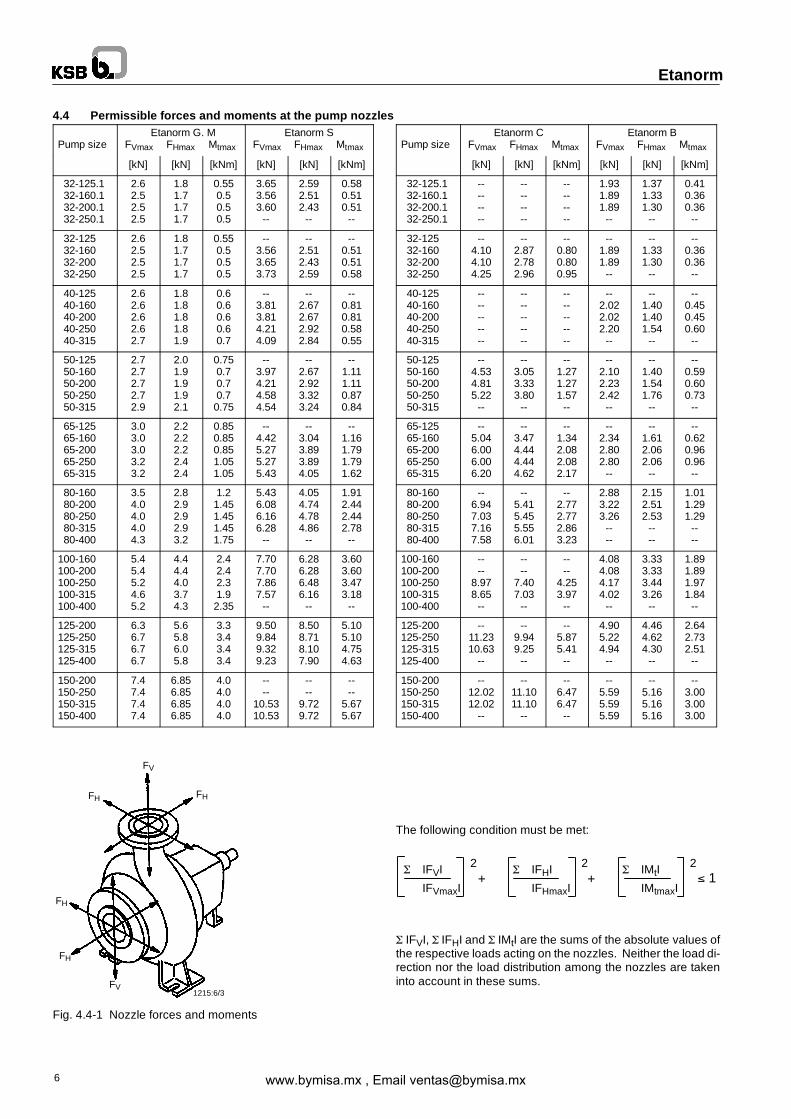
4.4 Permissible forces and moments at the pump nozzles
Pump sizeEtanorm G. M
FVmax FHmax Mtmax
Etanorm SFVmax FHmax Mtmax
[kN] [kN] [kNm] [kN] [kN] [kNm]
32-125.132-160.132-200.132-250.1
2.62.52.52.5
1.81.71.71.7
0.550.50.50.5
3.653.563.60--
2.592.512.43--
0.580.510.51--
32-12532-16032-20032-250
2.62.52.52.5
1.81.71.71.7
0.550.50.50.5
--3.563.653.73
--2.512.432.59
--0.510.510.58
40-12540-16040-20040-25040-315
2.62.62.62.62.7
1.81.81.81.81.9
0.60.60.60.60.7
--3.813.814.214.09
--2.672.672.922.84
--0.810.810.580.55
50-12550-16050-20050-25050-315
2.72.72.72.72.9
2.01.91.91.92.1
0.750.70.70.70.75
--3.974.214.584.54
--2.672.923.323.24
--1.111.110.870.84
65-12565-16065-20065-25065-315
3.03.03.03.23.2
2.22.22.22.42.4
0.850.850.851.051.05
--4.425.275.275.43
--3.043.893.894.05
--1.161.791.791.62
80-16080-20080-25080-31580-400
3.54.04.04.04.3
2.82.92.92.93.2
1.21.451.451.451.75
5.436.086.166.28--
4.054.744.784.86--
1.912.442.442.78--
100-160100-200100-250100-315100-400
5.45.45.24.65.2
4.44.44.03.74.3
2.42.42.31.92.35
7.707.707.867.57--
6.286.286.486.16--
3.603.603.473.18--
125-200125-250125-315125-400
6.36.76.76.7
5.65.86.05.8
3.33.43.43.4
9.509.849.329.23
8.508.718.107.90
5.105.104.754.63
150-200150-250150-315150-400
7.47.47.47.4
6.856.856.856.85
4.04.04.04.0
----
10.5310.53
----
9.729.72
----
5.675.67
Fig. 4.4-1 Nozzle forces and moments
Pump sizeEtanorm C
FVmax FHmax Mtmax
Etanorm BFVmax FHmax Mtmax
[kN] [kN] [kNm] [kN] [kN] [kNm]
32-125.132-160.132-200.132-250.1
--------
--------
--------
1.931.891.89--
1.371.331.30--
0.410.360.36--
32-12532-16032-20032-250
--4.104.104.25
--2.872.782.96
--0.800.800.95
--1.891.89--
--1.331.30--
--0.360.36--
40-12540-16040-20040-25040-315
----------
----------
----------
--2.022.022.20--
--1.401.401.54--
--0.450.450.60--
50-12550-16050-20050-25050-315
--4.534.815.22--
--3.053.333.80--
--1.271.271.57--
--2.102.232.42--
--1.401.541.76--
--0.590.600.73--
65-12565-16065-20065-25065-315
--5.046.006.006.20
--3.474.444.444.62
--1.342.082.082.17
--2.342.802.80--
--1.612.062.06--
--0.620.960.96--
80-16080-20080-25080-31580-400
--6.947.037.167.58
--5.415.455.556.01
--2.772.772.863.23
2.883.223.26----
2.152.512.53----
1.011.291.29----
100-160100-200100-250100-315100-400
----
8.978.65--
----
7.407.03--
----
4.253.97--
4.084.084.174.02--
3.333.333.443.26--
1.891.891.971.84--
125-200125-250125-315125-400
--11.2310.63--
--9.949.25--
--5.875.41--
4.905.224.94--
4.464.624.30--
2.642.732.51--
150-200150-250150-315150-400
--12.0212.02--
--11.1011.10--
--6.476.47--
--5.595.595.59
--5.165.165.16
--3.003.003.00
The following condition must be met:
π IFVI π IFHI π IMtI
IFVmaxI IFHmaxI IMtmaxI
π IFVI, π IFHI and π IMtI are the sums of the absolute values ofthe respective loads acting on the nozzles. Neither the load di-rection nor the load distribution among the nozzles are takeninto account in these sums.
www.bymisa.mx , Email [email protected]

L
Shim Shim
Foundation bolts
∫ 800Shim
1211.164
Grout with low shrinkageconcrete
Baseplate faces closed withformwork
Etanorm
7
4.5 Noise characteristicsRated ’A’-weighted surface sound pressure level pA [dB]
power Pump only Pump with motor
input PN(kW)
1450 1/mindB 1)
2900 1/mindB 1)
1450 1/mindB 2)
2900 1/mindB 2)
0.55 47 48 55 64
0.75 48 50 56 66
1.1 50 52 57 66
1.5 52 54 58 67
2.2 54 56 59 67
3.0 55 57 60 68
4.0 57 59 61 68
5.5 59 61 62 70
7.5 60 62 64 71
11.0 62 64 65 73
15.0 64 66 67 74
18.5 65 67 68 75
22.0 66 68 69 76
30.0 67 70 70 77
37.0 68 71 71 78
45.0 69 72 73 78
55.0 70 73 74 79
75.0 72 75 75 80
90.0 73 76 76 81
110.0 74 77 77 81
1) measured at a distance of 1 m from the pump outline (as per ISO 3744)2) measured at a distance of 1 m from the unit outline (as per ISO 3744)
The above noise characteristics apply to non-cavitating pumpoperation in the Qopt range.
4.6 Accessories
Drive surface-cooled IEC three-phase squirrel-cage motor
CouplingDesign: flexible couplingwith/without spacer sleeve
Baseplate channel section or folded steel plate for thecomplete unit (pump and motor) in torsion-resistant design.
Drive, coupling and baseplate can be supplied either by KSBorby the operator.
5 Installation at site5.1 Safety regulations
Electrical equipment operated in hazardous loca-tions must comply with explosion protection regula-
tions. This is indicated on the motor rating plate.If the equipment is installed in hazardous locations, theapplicable local explosion protection regulations and theregulations of the test certificate supplied with the equip-ment and issued by the responsible approval authoritiesmust be observed and complied with. The test certificatesupplied must be kept close to the location of operation foreasy access (e.g. foreman’s office).
5.2 Checks to be carried out prior to installationAll structural work required must have been prepared inaccordance with the dimensions stated in the dimensiontable / general arrangement drawing.The concrete foundations shall have sufficient strength(min. class X0) in accordance with DIN 1045.
Make sure that the concrete foundation has set firmly beforeplacing the unit on it. Its surface shall be truly horizontal andeven.
5.3 Installing the pump/unitAfter placing the pumpon the foundation, align it with the help ofa spirit level placed on the shaft/discharge nozzle. The correctdistance between the coupling halves as specified in the gen-eral arrangement drawing must be observed. Shims shall befitted between the baseplate/foundation frame and the founda-tion itself; they shall always be inserted to the left and right of thefoundation bolts and in close proximity to these bolts. For a bolt-to-bolt clearance of more than 800 mm, additional shims shallbe inserted halfway between the adjoining holes. All shimsmust lie perfectly flush.
Fig 5.3-1 Fitting required shimsTighten the foundation bolts evenly and firmly.Baseplates up to 400 mm wide are made of channel sectionand torsion-resistant in their own right; they need not begrouted.Baseplates more than 400 mm wide are made of folded steelplate and shall be grouted up to the upper edge through theholes 120 mm using low shrinkage concrete.
Fig. 5.3-2 Grouting the baseplate
5.3.1 Place of installationThe volute casing and discharge cover take on roughlythe same temperature as the medium handled. The
discharge cover and the bearing bracketmust not be insulated.Take the necessary precautions to avoid burns!
www.bymisa.mx , Email [email protected]

Caution
1211:128 /2
Supportfoot
Baseplate
Hex. head bolt
Adjusting screw
Lock nut
Support foot Baseplate Base
1211:166/2
Straight-edge
Gauge
1211:167/2
Straight-edge
Gauge
Caution
Etanorm
8
5.3.2 Aligning the pump/driveAfter fastening the baseplate on the foundation,the couplingmust be thoroughly checked and the
pump set be re-aligned (at the motor), if required .Prior to checking the alignment/re-alignment, loosen supportfoot 183 and re-tighten without transmitting any stresses orstrains.Coupling check and re-alignment must be effected even ifpump and motor are supplied completely assembled andaligned on a common baseplate.Motors with adjusting screw:In order to re-align the coupling, first loosen the 4 hex. headbolts on the motor as well as the lock nuts.Turn adjusting screw by hand or by means of an open-jawedwrench until the coupling alignment is correct. Then re-tightenthe 4 hex. head bolts and the lock nuts.
Fig. 5.3-3 Motor with adjusting screwsMotors without adjusting screwsAny differences in shaft centre height between the pump andthe motor are compensated by means of appropriately sizedbases. If pump and motor shaft centres are the same height,pump and motor are mounted directly on the baseplate.In order to re-align the coupling, loosen the four hex. head boltson themotor.Re-adjustment is effected by adding appropriatelysized sheet packs as per ZN 9 under the motor feet until thecoupling is correctly aligned.Then re-tighten the four hex. head bolts.
Fig. 5.3-4 Motor without adjusting screws
The pump set is correctly aligned if a straight-edge placed ax-ially on both coupling halves is the same distance from eachshaft at all points around the circumference. Make sure to turn
the measuring point by hand all the time. In addition, thedistance between the two coupling halves must remain thesame all around the circumference. Use a gauge to verify (seefigs. 5.3-4 and 5.3-5).
Fig. 5.3-5 Aligning a flexible coupling without spacer sleeve
Fig. 5.3-6 Aligning a flexible coupling with spacer sleeveThe radial and axial deviation between the two coupling halvesmust not exceed 0.1 mm.This must also be ensured at operating temperature and underinlet pressure.Improper alignment of the unit can cause damage to both thecoupling and the unit itself!
5.4 Connecting the pipingNever use the pump itself as an anchorage pointfor the piping.
The piping-induced forces and moments acting on the pumpflanges (e.g. due to warped pipelines or thermal expansion)must not exceed the permissible forces andmoments specifiedin section 4.4.Suction lift lines shall be laid with a rising slope towards thepump and suction head lines with a downward slope towardsthe pump.The pipelines shall be anchored in close proximity to the pumpand connected without transmitting any stresses or strains.Their weight must not be carried by the pump.With short pipelines, the nominal diameters should be at leastequal to the nominal diameters of the pump nozzles. For longpipelines, the most economical nominal diameter has to be de-termined from case to case.
Adapters to larger diameters should have a diffuser angle of ap-prox. 8 in order to avoid any increase in pressure losses.It is recommended to install check and shut-off elements in thesystem, depending on the type of plant and pump.Thermal expansions of the pipelines must be compensated byappropriate measures so as not to impose any extra loads onthe pump.
An excessive, impermissible increase in the pipelineforces may cause leaks on the pump where the medium
handled can escape into the atmosphere.Danger to life when hot media are handled!
www.bymisa.mx , Email [email protected]

1211:19/4
1212:5
Caution
0910:3/2
Etanorm
9
The flange covers on the pump suction and discharge nozzlesmust be removed prior to installation in the piping.Before commissioning new installations thoroughly clean, flushand blow through all vessels, pipelines and connections. Oftenwelding beads, scale and other impurities only come off after acertain period of operation. Fit a strainer in the suction line toprevent them fromentering the pump. The total cross-section ofthe holes in the strainer shall be three times the cross-section ofthe pipeline in order to avoid excessive pressure loss acrossthe strainer due to clogging. Conical strainers with laidin wiremesh having a mesh width of 0.5 mm and a wire diameter of0.25 mm, of corrosion-resistant material, shall be used.
1 Strainer housing2 Fine screen3 Perforated plate4 Pump suction nozzle5 Differential pressure gauge
Bild 5.4-1 Conical strainer for the suction line
5.4.1 Vacuum balance lineWhere liquid has to be pumped out of a vessel under vacuum, itis advisable to install a vacuumbalance line. This line shallhavea nominal diameter of at least 25 mm and must be arranged tolead into the vessel at a point above the highest permissibleliquid level.An additional pipeline fitted with a shut-off valve – from thepump discharge nozzle to the balance line – facilitates ventingof the pump before start-up.
A Main shut-off valveB Vacuum balance lineC Shut-off valveE Vacuum-tight shut-off valveR Swing check valveV Vessel under vacuumZ Intermediate flangeFig. 5.4-2 Suction line and vacuum balance line
5.4.2 Auxiliary connectionsThe dimensions and locations of the auxiliary connections(barrier liquid, flushing liquid, controlled leakage etc.) are indi-cated in the general arrangement drawing or piping layout.
Connecting and activating the auxiliary feed linesis required for proper functioning of the pump and
therefore of vital importance!
5.5 Connection to power supplyConnection to the power supply must be effected by atrained electrician only.
The applicable DIN VDE regulations 0100 and, for explosion-proof units, 0165 must be complied with.
Check available mains voltage against the data on the motorrating plate and select appropriate start-up method.All connections shall be effected in accordance with thetechnical specifications issued by the local energy supplycompany.We strongly recommend to use a motor protection device.DIN VDE 0170/0171 stipulates that explosion-proof motors,type of protection IP 54, increased safety Ex EEx, temperatureclass T3, must always be connected via a motor protectionswitch.
5.5.1 Motor connectionIn compliance with DIN VDE 0530 – Part 8, the three-phasemotors are always wired for clockwise rotation (looking at themotor shaft stub).The pump’s direction of rotation is anti-clockwise (looking at thesuction flange).For the motor’s direction of rotation to match the pump’s direc-tion of rotation, the motor must be connected as shown in fig.5.6-1 or 5.6-2, as applicable.ϖ configuration (low voltage)
Fig. 5.5-1 Connection diagram for three phase motors,ϖ configuration
Y configuration (high voltage)
Fig. 5.5-2 Connection diagram for three phase motors,Y configuration
If required, connect the PTC resistors as per DIN44081/44082 with the tripping unit in accordance with fig.5.5-3.
Fig. 5.5-3 Connection diagram for PTC resistors
www.bymisa.mx , Email [email protected]

Caution
Oil level in reservoirduring filling procedure
Constant-leveloiler
Position of reservoir fortopping up oil
Oil level in bearing bracketand connection elbow
Vent/filler plug
1211:11/5
Caution
Caution
Caution
Caution
Caution
Etanorm
10
5.5.2 Setting the time relayMake sure that in the case of three-phasemotors with star-deltastarting method switching over from star to delta will be effectedat very short intervals. Prolonged switch-over intervals willresult in pump damage.Time relay setting for star-delta starting:
Motor rating Y time to be set 30 kW> 30 kW
< 3 s.< 5 s.
5.5.3 Checking the direction of rotationThe motor’s direction of rotation must correspond to the direc-tion indicated by the arrow on the pump’s volute casing (clock-wise seen from themotor end). Verify by switching themotor onand then off again immediately.If the pump runs in the wrong direction of rotation, interchangeany two phases L1, L2 or L3 of the power cable in the motor ter-minal box.
6 Commissioning, start-up / Shutdown6.1 Commissioning
Before starting up the pump make sure that- the pump unit has been properly connected to the electricpower supply and is equipped with all protection devices;
- the pump has been primed with the liquid to be pumped;- the direction of rotation has been checked;- all auxiliary lines have been properly connected.
6.1.1 LubricantsGrease-lubricated bearingsGrease-lubricated bearings have been packed with grease atthe factory.Oillubricated bearingsThe bearing bracket has to be filled with lubricating oil. QualityC, CL, CLP46 as per DIN 51517.
Fig. 6.1-1 Oil fillProcedure:Remove vent plug 672.Pour in the oil through the vent plug tap-ping hole after having hinged down the reservoir of the con-stant-level oiler until oil appears in the vertical portion of the con-nection elbow (Fig. 6.1-1). Then fill the reservoir of theconstant-level oiler with oil and snap it back into operating posi-tion. Fit vent plug again. After a short time check whether the oillevel in the reservoir has dropped.It is important to keep the reservoir properly filled at all times!
The oil level shall always be below the the level ofthe vent opening arranged at the top edge of the
connection elbow.
To check the oil level, we recommend to slowly drain oil throughthe drain plug until the constant-level oiler starts to operate, i.e.until air bubbles can be seen in the oiler.If no constant-level oiler is provided on the bearing bracket,make sure that the oil level reaches the centreline of the oil levelsight glass arranged at the side of the bearing bracket.
6.1.2 Shaft sealShaft seal (see sections 7.4.4 and 7.5.2)
6.1.3 Priming the pump and checks to be carried outBefore start-up, the pump and the suction line must be ventedand primed with the liquid to be pumped. The shut-off valve inthe suction line must be fully open.Fully open all auxiliary lines provided (barrier, flushing liquid,etc.) and check the throughflow. Open the shut-off valve in thevacuum balance line (if any), and close the vacuum-tight shut-off valve E (fig. 5.4-2).
Dry-running will result in increased wear andmust be avoided.
6.1.4 Final checkRe-check the alignment as described in section 5.3.2. It mustbe easy to rotate the coupling/shaft by hand.
Check the integrity and proper functioning of allconnections.
6.1.5 Contact guardIn compliance with the accident prevention regulationsthe pumpmust not be operated without a coupling guard.
If the customer specifically requests not to include a couplingguard in our delivery, then the operator must supply one!
6.1.6 Start-upAlways make sure that the shut-off valve in the discharge line isclosed before the pump is started up! Only after the pump hasreached full rotational speed shall the shut-off valve in thedischarge line be opened slowly and adjusted to comply withthe duty point.
After the operating temperature has beenreached and/or in the event of leakage, switch off
the unit and re-tighten hex. nuts 920.3 and 920.5.Check the coupling alignment as described in section 5.3.2 andre-align, if necessary. For leakage at the gland packing pleaserefer to section 7.2.1.
6.1.7 ShutdownClose the shut-off valve in the discharge line.If the discharge line is equipped with a non-return or checkvalve, the shut-off element may remain open if there is back-pressure.
The shut-off valve in the suction line must not be closedwhen switching off the pump.
Switch off the motor, making sure that the unit runs downsmoothly to a standstill.Depending on the type of installation, the pump should have asufficient after-run time – with the heat source shut off – until themedium handled has cooled down sufficiently to avoid a heatbuild-up in the pump.For prolonged shutdown, close the shut-off valve in the suctionline. Close the auxiliary connections.The shaft seal in pumps where the liquid is fed in under vacuummust also be supplied with barrier liquid during standstill.In the event of frost and/or prolonged shutdowns, the pumpmust be drained or otherwise protected against freezing.
6.2 Operating limits
6.2.1 Temperature of the medium handledDonot operate the pumpat product temperaturesexceeding those specified on the data sheet or
the name plate.
www.bymisa.mx , Email [email protected]

Caution
Caution
Etanorm
11
6.2.2 Switching frequency
To prevent high temperature increases in the motor and ex-cessive loads on the pump, coupling, motor, seals and bear-ings, the switching frequency shall not exceed the followingnumber of start-ups per hour (h).Etanorm G, M, S: 15 start-ups/hEtanorm B, C: 6 start-ups/h
6.2.3 Minimum flow
If the plant configuration is such that the pump might be oper-ated against a closed discharge side valve, a minimum flow oft - 30 to +70 C ≈ 15 % of Qopt.t >70 to +140 C ≈25 % of Qopt.must be ensured during this period.
6.2.4 Density of medium handled
The pump input power will increase in proportion to the densityof the fluid handled. To avoid overloading of the motor, pumpand coupling, the density of the medium must comply with thedata specified on the purchase order.
6.3 Shutdown / Storage / Preservation
EachKSBpump leaves the factory carefully assembled. If com-missioning is to take place some time after delivery, we recom-mend that the following measures be taken for pump storage.
6.3.1 Storage of new pumps
- New pumps are supplied by our factory duly prepared forstorage.Maximum protection for up to 12 months, if the pumps areproperly stored indoors.
- Store the pump in a dry location.
6.3.2 Measures to be taken for prolonged shutdown
1.The pump remains installed; periodic check of operationIn order tomake sure that the pump is always ready for instantstart-up and to prevent the formation of deposits within thepump and the pump intake area, start up the pump set reg-ularly once a month or once every 3 months for a short time(approx. 5 minutes) during prolonged shutdown periods.Prior to an operation check run ensure that there is sufficientliquid available for operating the pump.
2.The pump is removed from the pipe and storedBefore putting the pump into storage, carry out all checks andmaintenance work specified in section 7.1. Then apply ap-propriate preservatives:- Spray-coat the inside wall of the pump casing, and in par-ticular the impeller clearance areas, with a preservative.Spray the preservative through the suction and dischargenozzles. It is advisable to close the pumpnozzles (e.g.withplastic caps or similar).
6.4 Returning to service after storage
Before returning the pump to service, carry out all checks andmaintenance work specified in sections 7.1 and 7.2.
In addition, the instructions laid down in the sections on”Commissioning” (6.1) and ”Operating limits” (6.2) must
be observed.
Immediately following completion of the work, all safety-relevant and protective devices must be re-installed
and/or re-activated.
7 Servicing / Maintenance7.1 General instructions
The operator is responsible for ensuring that all maintenance,inspection and installation work be performed by authorized,qualified specialist personnel who are thoroughly familiar withthe manual.
A regular maintenance schedule will help avoid expensive re-pairs and contribute to trouble-free, reliable operation of thepump with a minimum of maintenance expenditure and work.
Work on the unit must only be carried out with theelectrical connections disconnected. Make sure that
the pump set cannot be switched on accidentally.
Pumps handling liquids posing health hazards mustbe decontaminated. When draining the fluid pumped
see to it that there is no risk to persons or the environment.All relevant laws must be heeded.
7.2 Servicing / Inspection
7.2.1 Supervision of operation
The pump must run quietly and free from vibra-tions at all times.
The pump must never be allowed to run dry.
Do not run the pump against a closed shut-off valve forprolonged periods of time so as to avoid heating up of the
fluid pumped.
Max. permissible room temperature 40 �C.
The bearing temperature may exceed room temperature by upto 50 �C,butmust never rise above 90 �C (measured on the out-side of the bearing bracket).Verify correct oil level as described in section 6.1.1.
For required minimum flows please refer to section 6.2.3.
During pump operation the shut-off valve in the suctionline must not be closed.
The gland packing, if fitted, must drip slightly during operation.The gland cover shall only be tightened gently.
Undo hex. head bolt(s) 901.3, then remove cover plate 81-92 atbearing bracket 330 before carrying out any maintenance workon the gland packing.
Make sure to fit the cover plate again before re-startingthe pump.
If pure graphite packings are used, there must always be leak-age. For permissible leakage rates please refer to section7.5.2.3. If the gland shows excessive leakage after a significantperiod of operation, evenly tighten the gland nuts by 1/6 of aturn, then check the leakage. If the gland cover cannot be tigh-tened any further, add a new packing ring.Normally it will not benecessary to replace the complete packing.
The mechanical seal, if fitted, shows only slight or invisible (va-pour) leakage during operation. It is maintenance-free.
Any stand-by pumps installed shall be switched on and then im-mediately off again once a week to keep them operational.
Attention shall be paid to the correct functioning of the auxiliaryconnections.
If the flexible coupling elements begin to showsigns of wear, they must be replaced in due time.
www.bymisa.mx , Email [email protected]

Caution
Caution
Etanorm
12
7.2.2 Lubrication and lubricant change
7.2.2.1Lubrication
The rolling element bearings are lubricated with grease or min-eral oil. For the required quantity please refer to section 7.2.2.4.
7.2.2.2Grease quality / Grease changeThe bearings are packed with high-quality lithium-soap grease.Under normal conditions the grease-lubricated bearingswill runfor 15,000 operating hours or 2 years. Under unfavourable op-erating conditions, e.g. high room temperature, high atmos-pheric humidity, dust-laden air, aggressive industrial atmos-phere etc., the bearings shall be checked earlier and cleanedand re-lubricated, if required.Use a high-quality lithium-soap grease, free of resin and acid,not liable to crumble and with good rust-preventive characteris-tics. The grease should have a penetration number between 2and 3, corresponding to aworked penetration between 220 and295 mm/10. Its drop point must not be below 175�C. The bear-ing cavities must only be half-filled with grease.If required, the bearingsmay be lubricated with greases of othersoap bases. Since greases of differing soap basesmust not bemixed, the bearings must be thoroughly cleaned beforehand.The re-lubrication intervals required must then be adjusted tothe greases used.
7.2.2.3Oil changeThe first oil change shall be carried out after 300 operatinghours, the following ones after every 3000 operating hours, atleast once a year.
Fig. 7.2-1 Oil lubrication
Part No. Description Part No. Description321.1 Deep-groove ball
bearing638 Constant-level oiler
360.2 Bearing cover 672 Vent plug400.2 Gasket 903.3 Screwed plug421 Lip seal 13 B Oil drain507 Thrower 13 D Oil – filling and venting
Procedure:Remove screwed plug 903.3 below constant-leveloiler 638anddrain off the oil into a suitable vessel. After drainage of the bear-ing bracket, screw in the plug again and fill with fresh oil as de-scribed in section 6.1.1.
Please observe the local laws applicable to thedisposal of such substances!
7.2.2.4Deep-groove ball bearings / Lubricant quantityPump
Deep-groove ball bearing to DIN 625
Shaft unit1)
Grease lubrication Oil lubrication
Code Grease perbearing (ap-prox. qty. ingrams)
Code Oil perbearingbracketapprox.qty. inlitres
253555
6305 Z C36307 Z C36311 Z C3
51015
6305 C36307 C36311 C3
0.20.350.65
1) For shaft unit / pump size combinations refer to section 7.6.1
for KSB IEC motor
Deep-groove ball bearings to DIN 625Code Grease per bearing
(approx. qty. in grams)
6004 C3 26205 C3 36206 C3 46208 C3 66209 C3 76210 C3 76212 C3 76213 C3 116215 C3 136216 C3 156317 C3 176217 C3 176319 C3 22
Closed bearings greased for life (2 Z or 2 RS bearings) cannotbe washed out and refilled. They will have to be replaced bynew ones.
7.3 Drainage / Disposal
If the pump was used for handling liquids posing healthhazards, see to it that there is no risk to persons or the
environment when draining the medium. All relevant lawsmustbe heeded. If required, wear safety clothing and a protectivemask!The flushing liquid used and any liquid residues in the pumpmust be properly collected and disposed of without posing anyrisk to persons or the environment.
7.4 DismantlingBefore dismantling the pump, secure it so as tomake sure it cannot be switched on accidentally.
The shut-off valves in the inlet / suction and discharge pipesmust be closed.The pump casing must have cooled down to ambient tempera-ture.Pump pressure must have been released and the pump musthave been drained.
7.4.1 Fundamental instructions and recommendationsRepair andmaintenance work to the pumpmust only be carriedout by specially trained personnel, using original spare parts(see 2.7).
www.bymisa.mx , Email [email protected]

Caution
Caution
2746:17/2
Etanorm
13
Observe the safety regulations laid down in section 7.1.Any work on the motor shall be governed by the specifica-tions and regulations of the respective motor supplier.Dismantling and reassembly must always be carried out inthe sequence shown in the relevant exploded views onpages 19 to 23.In the case of damage or pump failure please contact ournearest customer service centre.
For customer service centres please refer to the attached list ofaddresses.
7.4.2 Preparations for dismantling1 Interrupt power supply.2 On oil-lubricated pumps drain off the oil as described in
7.2.2.3.3 Disconnect and remove all auxiliary pipework.4 Remove the coupling guard.5 Coupling without spacer sleeve.5.1 Dismantling of pump unit:5.1.1 Disconnect the motor from the power supply.5.1.2 Unbolt the motor from the baseplate.5.1.3 Shift the motor to decouple it from the pump.5.1.4 Unbolt the discharge and suction nozzle from the piping.5.1.5 Unbolt the pump from the baseplate.5.2 Volute casing remains on the baseplate and in the pipe-
line when the unit is dismantled:5.2.1 Disconnect the motor from the power supply.5.2.2 Unbolt the motor from the baseplate.5.2.3 Shift the motor to decouple it from the pump.5.2.4 Detach support foot 183 from the baseplate and undo
hex. nuts 920.3 or 920.5 on the discharge cover.5.2.5 Pull the bearing bracket with discharge cover and cpl.
rotor out of the casing (back pull-out unit).On larger pumps suspend or support thebearing bracket end in order to preventthe back pull-out unit from tilting.
6 Spacer-type coupling.6.1 Dismantling the pump unit:6.1.1 Disconnect the motor from the power supply.6.1.2 Remove the coupling spacer.6.1.3 Unbolt the discharge and suction nozzle from the piping.6.1.4 Unbolt the pump from the baseplate.6.2 Volute casing remains on the baseplate and in the pipe-
line when the unit is dismantled:6.2.1 Disconnect the motor from the power supply.6.2.2 Remove the coupling spacer.6.2.3 Detach support foot 183 from the baseplate and undo
hex. nuts 920.3 or 920.5 on the discharge cover.6.2.4 Pull the bearing bracket with discharge cover and cpl.
rotor out of the casing (back pull-out unit).On larger pumps suspend or support the bearingbracket end in order to prevent the back pull-out
unit from tilting.After a prolonged period of operation the individualcomponentsmay be hard to pull off the shaft. If this is the case, use a brandname penetrating agent and/or - if possible - an appropriatepull-off device.Under no circumstances use force.
7.4.3 PumpDismantle the pump in the sequence shown in the explodedviews on pages 19 to 23.
7.4.4 Mechanical sealIn order to replace the mechanical seal the pump must be dis-mantled.
After removing the impeller 230 pull the mechanical seal 433 offthe shaft by hand.
Prior to reassembly, clean the shaft sleeve 523 and touch upgrooves or scratches, if any, with a polishing cloth. If the scoremarks are still visible, fit a new shaft sleeve. Clean seat ringlocation in seat ring holder 476.
7.5 Reassembly
7.5.1 PumpThe pump shall be reassembled in accordance with the rules ofsound engineering practice.
The locating surfaces of the individual components must becoated with graphite or similar before reassembly. The sameapplies to bolted connections.
O-rings shall be examined for signs of damage and replaced bynew ones, if necessary.
Gaskets shall always be replaced by new ones.Make sure thatnew gaskets have the same thickness as the old ones.
Gaskets of asbestos-free materials or graphite must always befitted without using lubricants.
Avoid the use of mounting aids as far as possible. Should amounting aid be required after all, use a commercially availablecontact adhesive (e.g. Pattex) or sealing agent (HYLOMAR orEpple 33). The adhesive shall only be applied at selected pointsand in thin layers. Do not use cyanoacrylate adhesives (quick-setting adhesives).When fitting the deep-groove ball bearings, make sure that thebearing side with cover plate rests against the shaft shoulder.
Fig. 7.5-1 Fitting the deep-groove ball bearings
If the seal area between the impeller neck and the casing wearring is worn, the casing wear rings 502.1 and 502.2 (if fitted)must be replaced by new ones.
Clearances:Etanorm G, M, S, Bas-new condition 0.3 mm in diameter, max. permissibleenlargement to 0.9 mm in diameterEtanorm Cas-new condition 0.5 mm in diameter, max. permissibleenlargement to 1.5 mm in diameterReassembly is effected in reverse order to dismantling. Makesure to assemble the components in their correct sequence.
7.5.2 Shaft sealThoroughly clean the packing chamber and shaft protectingsleeve before packing the gland.
www.bymisa.mx , Email [email protected]

1211:12/4
1152:15/2
1167
Caution
Etanorm
14
7.5.2.1Gland packing chamber
Fig. 7.5-2 Gland packing chamber
Dimensions in mmShaft unit1)
Gland packingchamber
Packingring
No. of rings 2)
di da l
25 30 46 45 V 8 x 126 3 packing rings1 lantern ring
35 40 60 56 V 10 x 165 3 packing rings1 lantern ring
55 50 70 56 V 10 x 196 3 packing rings1 lantern ring
1) For shaft unit / pump size combinations please refer to section 7.6.12) For operation with positive suction head and suction pressure > 0.5bar, the lantern ring is replaced by 2 packing rings.
7.5.2.2Packing ring cut to size
Fig. 7.5-3 Packing ring cut to sizeThe first packing ring 461 is inserted and pushed home usingstuffing box ring 454.
Each subsequent packing ring is inserted separately with itsjoint displaced by approx. 90� in relation to the previous oneand pushed into the packing chamber using the stuffing boxring.Tighten the gland cover gently and evenly. It must be easy torotate the rotor.
7.5.2.3Pure graphite packing ring
Fig. 7.5-4 Split packing ring, pure graphite
The pure graphite gland packing is a high-quality precisionsealing element which requires careful handling during installa-tion.
Follow the installation instructions for packing rings cut to size.
The packing rings made of pure graphite must always fit snuglyin the stuffing box. There must be a gap between the shaftprotecting sleeve and the packing rings.
Before starting up the pump, tighten the gland nuts evenly byhand only (check that the cover is mounted in central positionand at right angles using a feeler gauge). The gland must leakafter the pumphas been primed.Allow the pump to run forabout5minuteswith steady leakagebefore tightening the glandcovernuts by 1/6 of a turn and then check the leakage for about 5min-utes. Continue tightening at 5 minute intervals until the leakagerate is acceptable.
Leakage rate:min. 10 cm3/minute, max. 20 cm3/minute.
Slightly slacken the gland nuts if leakage is insuffient.
If there is no leakage at all:
- switch off the pump immediately
- slacken the gland nuts and repeat the start-up procedure.
After adjustment observe the leakage for approx. 2 hours atmax. product temperature 120 �C/140 �C.
Then check – with product pressure at its minimum – whetherthere is sufficient leakage.
7.5.2.4Mechanical seal
Reassembly is effected in reverse order to dismantling.The following rulesmust be observed when fitting amechanicalseal:Extreme care and cleanliness.The protective wrapping of the contact faces shall only beremoved immediately before assembly takes place.Take care not to damage the seal faces and O-rings.Clean the shaft and the seat ring seat in the discharge coverand gently remove any deposits.When fitting the seal, shaft sleeve 523may bewettedwithwaterto reduce the friction forces.
Ethylene propylene rubber elastomers mustnever come into contact with oil or grease. Water
shall be used as a lubricant during fitting.
Press the seat ring into discharge cover 163 by hand or fingersonly. Make sure that the pressure is applied evenly.
www.bymisa.mx , Email [email protected]
Version withclamped discharge cover
A B F C
D
1211:147/2
F
G
1211:148/2
Etanorm
15
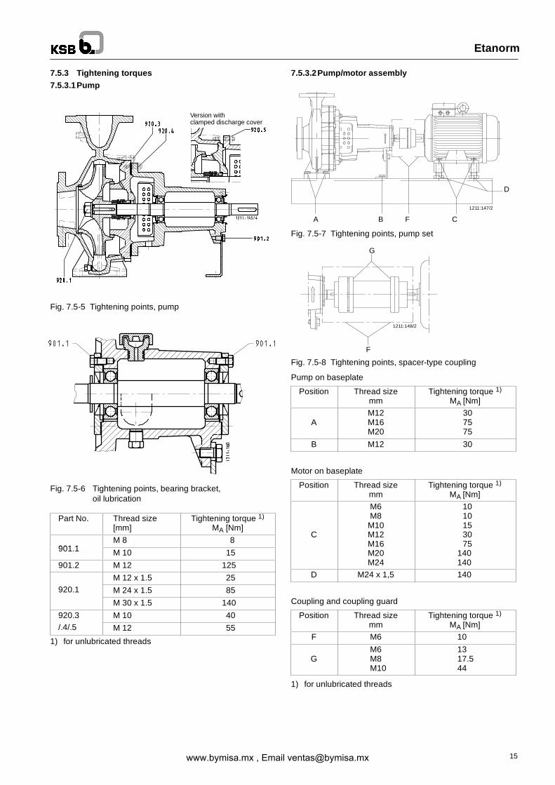
7.5.3 Tightening torques7.5.3.1Pump
Fig. 7.5-5 Tightening points, pump
Fig. 7.5-6 Tightening points, bearing bracket,oil lubrication
Part No. Thread size[mm]
Tightening torque 1)
MA [Nm]
901 1M 8 8
901.1 M 10 15
901.2 M 12 125
M 12 x 1.5 25920.1 M 24 x 1.5 85
M 30 x 1.5 140
920.3 M 10 40/.4/.5 M 12 55
1) for unlubricated threads
7.5.3.2Pump/motor assembly
Fig. 7.5-7 Tightening points, pump set
Fig. 7.5-8 Tightening points, spacer-type coupling
Pump on baseplate
Position Thread sizemm
Tightening torque 1)
MA [Nm]
AM12M16M20
307575
B M12 30
Motor on baseplate
Position Thread sizemm
Tightening torque 1)
MA [Nm]
C
M6M8M10M12M16M20M24
1010153075
140140
D M24 x 1,5 140
Coupling and coupling guard
Position Thread sizemm
Tightening torque 1)
MA [Nm]F M6 10
GM6M8M10
1317.544
1) for unlubricated threads
www.bymisa.mx , Email [email protected]

Etanorm
16
7.6 Spare parts stock
7.6.1 Ordering spare parts
When ordering spare parts please always quote the followingdata stated on the name plate.
e.g.:
Type Etanorm G 50-250
Ident No. 48 819 673
Design G1
Works No. 4-917-451 778
or on the volute casing, e.g. .: EN 50-250
7.6.2 Recommended spare parts stock for 2 years’ continuous operation to DIN 24 296
Part Description Number of pumps (including stand-by pumps)
No. 2 3 4 5 6 and 7 8 and 9 10 and more
Pumps with mechanical seals: Quantity of spare parts
210 Shaft 1 1 1 2 2 2 20 %
230 Impeller (including casing wear ring 502.2) 1 1 1 2 2 2 20 %
321 Deep-groove ball bearing (set) 1 1 2 2 2 3 25 %
330 Bearing bracket - - - - - 1 2 off
433 Mechanical seal: 1 1 2 2 2 3 25 %
502.1 Casing wear ring 2 2 2 3 3 4 50 %
523 Shaft sleeve 2 2 2 3 3 4 50 %
- Gaskets (set) 4 6 8 8 9 10 100 %
Pump with gland packing
461 Gland packing (set) instead of parts 4 4 6 6 6 8 100 %
524 Shaft protecting sleeve 433, 523 2 2 2 3 3 4 50 %
www.bymisa.mx , Email [email protected]

Volutecasing
Shaft
Impeller
Shaftunits
-glandpacking
-mechanicalseal
Gland
packing
Casingwearring
Casingwearring
Shaftsleeve
Discharge
cover
Discharge
cover
102
163.1
163.2
210
230
433
461
502.1
502.2
523
321
suctionside
dischargeside
Shaftprotectingsleeve
524
Mechanicalseal
Deep-groove
ballbearing
Same number meanssame component
Components differ Component not fitted11
X
Component interchangeable with Etabloc
Etanorm
17
7.6.3 Interchangeabilityof Etanorm andEtabloccomponentsand interchangeabilityof componentsamongeachother
Description
Part No.
Etanorm
32-125.1 25 ○ 1 12 1 ○ 1 1 1 1 X 1 132-160.1 25 ○ 1 12 1 1 1 1 1 1 3 1 132-200.1 25 ○ 4 15 1 2 1 1 1 1 3 1 132-250.1 25 ○ 6 17 1 3 1 1 1 1 4 1 132-125 25 ○ 1 12 1 ○ 1 1 1 1 X 1 132-160 25 ○ 1 12 1 1 1 1 1 1 3 1 132-200 25 ○ 4 15 1 2 1 1 1 1 3 1 132-250 25 ○ 6 17 1 3 1 1 1 1 4 1 140-125 25 ○ 1 12 1 ○ 1 1 1 2 X 1 140-160 25 ○ 1 12 1 ○ 1 1 1 2 3 1 140-200 25 ○ 4 15 1 ○ 1 1 1 ○ 3 1 140-250 25 ○ 6 17 1 ○ 1 1 1 2 4 1 140-315 35 ○ ○ ○ 2 ○ 2 2 2 2 13 2 250-125 25 ○ 1 12 1 ○ 1 1 1 3 3 1 150-160 25 ○ 1 12 1 ○ 1 1 1 3 3 1 150-200 25 ○ 4 15 1 ○ 1 1 1 3 3 1 150-250 25 ○ 6 17 1 ○ 1 1 1 3 4 1 150-315 35 ○ 9 20 2 ○ 2 2 2 5 10 2 265-125 25 ○ 1 12 1 ○ 1 1 1 5 3 1 165-160 25 ○ 2 13 1 ○ 1 1 1 5 9 1 165-200 25 ○ ○ ○ 1 ○ 1 1 1 5 9 1 165-250 35 ○ ○ ○ 2 ○ 2 2 2 9 13 2 265-315 35 ○ 9 20 2 ○ 2 2 2 9 10 2 280-160 25 ○ 2 13 1 ○ 1 1 1 6 9 1 180-200 35 ○ 3 14 2 ○ 2 2 2 6 10 2 280-250 35 ○ 7 18 2 ○ 2 2 2 6 10 2 280-315 35 ○ 9 20 2 ○ 2 2 2 6 10 2 280-400 55 ○ 11 22 3 ○ 3 3 3 10 8 3 3100-160 35 ○ 3 14 2 ○ 2 2 2 7 10 2 2100-200 35 ○ 3 14 2 ○ 2 2 2 7 10 2 2100-250 35 ○ 7 18 2 ○ 2 2 2 7 10 2 2100-315 35 ○ 9 20 2 ○ 2 2 2 7 10 2 2100-400 55 ○ 11 22 3 ○ 3 3 3 7 8 3 3125-200 35 ○ 5 16 2 ○ 2 2 2 8 11 2 2125-250 35 ○ 8 19 2 ○ 2 2 2 8 14 2 2125-315 55 ○ 10 21 3 ○ 3 3 3 8 8 3 3125-400 55 ○ 11 22 3 ○ 3 3 3 8 8 3 3150-200 35 ○ 5 16 2 ○ 2 2 2 ○ 11 2 2150-250 35 ○ 8 19 2 ○ 2 2 2 12 14 2 2150-315 55 ○ 10 21 3 ○ 3 3 3 12 8 3 3150-400 55 ○ 11 22 3 ○ 3 3 3 12 8 3 3
www.bymisa.mx , Email [email protected]

Pum
pdeliversinsufficientflowrate
Motorisoverloaded
Excessive
pumpdischargepressure
Excessive
bearingtemperature
Excessive
leakageattheshaftseal
Vibrations
duringpumpoperation
Leakageatthepump
Excessive
riseoftemperatureinside
thepump
Etanorm
18
8 Trouble-shooting
Cause Remedy 1)
* Pump delivers against an excessively high discharge pressure. Re-adjust to duty point.
* Excessively high back pressure. Check plant for impurities.Fit a larger impeller. 2)Increase the speed (turbine, I.C. engine).
* * * Pump or piping are not completely vented or primed. Vent and/or prime.
* Supply line or impeller clogged. Remove deposits in the pump and/or piping.
* Formation of air pockets in the piping. Alter piping layout.Fit a vent valve.
* * * Suction head is too high/NPSH- available (positive suction head)is too low.
Check/alter liquid level.Install pump at a lower level.Fully open shut-off valve in the suction line.Change suction line, if the friction losses in the suction line are toohigh.Check any strainers installed/suction opening.Observe permissible speed of pressure fall.
* Air intake at the shaft seal. Clean barrier liquidduct, supply external barrier liquid, if necessary,or increase its pressure.Fit new shaft seal.
* Wrong direction of rotation. Interchange two of the phases of the power supply cable.
* Speed is too low. 2) Increase speed.
* * Wear of internal pump parts. Replace worn components by new ones.
* * Pump back pressure is lower than specified in the purchaseorder.
Adjust duty point accurately.In the case of persistent overloading, turn down impeller.2)
* The density or viscosity of the fluid pumped is higher than speci-fied in the order.
2)
* * Gland cover too tight or askew. Correct.
* * Speed is too high. Reduce speed. 2)
* Defective seal element Replace the gasket between volute casing and discharge cover.
* Worn shaft seal. Fit new shaft seal.Check flushing or barrier liquid pressure.
* * Score marks or roughness on shaft protecting sleeve / shaftsleeve.
Replace shaft protecting sleeve / shaft sleeve.Fit new shaft seal.
* Vibrations during pump operation. Improve suction conditions.Re-align the pump.Re-balance the impeller.Increase pressure at the pump suction nozzle.
* * * The unit is misaligned. Re-align.
* * * Pump is warped or sympathetic vibrations in the piping. Check piping connections and secure fixing of pump. If required,reduce the distances between the pipe clamps.Fix the pipelines using anti-vibration material.
* Increased axial thrust. 2) Clean balancing holes in the impeller.Fit new wear rings.
* * Insufficient or excessive quantity of lubricant or unsuitable lubric-ant.
Top up, reduce or change lubricant.
* Non-compliance with specified coupling distance. Correct distance according to the general arrangement drawing.
* * Motor is running on two phases only. Replace the defective fuse.Check the electric cable connections.
* Rotor is out of balance. Clean the impeller.Re-balance the impeller.
* Defective bearing(s). Fit new bearings.
* * Insufficient rate of flow. Increase the minimum rate of flow.
* Incorrect inflow of circulation liquid. Increase the free cross-section.
1) Pump pressure must be released before attempting to remedy faults on parts which are subjected to pressure.
2) Request particulars.
www.bymisa.mx , Email [email protected]

Etanorm
19
9 Related documents9.1 Exploded view / List of components Etanorm with standardized mechanical seal and bolted-on discharge cover
Etanorm 32-200.1 50-200 80-250 125-25032-250.1 50-250 80-315 125-40032-200 50-315 80-400 150-25032-250 65-200 100-250 150-40040-200 65-250 100-31540-250 65-315 100-40040-315
⊏ Supplied in packaging units only
Part No. Description Part No. Description Part No. Description
102 Volute casing163.2 Discharge cover183 Support foot210 Shaft230 Impeller321 Deep-groove ball bearing330 Bearing bracket360.1 Bearing cover400.1/.3 Gasket411 Joint ring
433 Mechanical seal502.1/.2 Casing wear ring523 Shaft sleeve550 Disc 1)
81-92 Cover plate901.1-3 Hex. head bolt902.1/.2 Stud903.1 Screwed plug 3)
920.1/.3/.4 Hex. nut930.3 Spring washer
932 Circlip940.2 Key 2)
940.3 Key
1M Pressure gauge connection6B Casing drain6D Medium priming8B Leakage drain
1) only on Etanorm with shaft unit 25 5)
2) On Etanorm with shaft unit 55 5) = 2 keys3) On Etanorm C, S: additional joint ring 411.5 (not shown in drawing)5) For shaft unit / pump size combinations please refer to section 7.6.3
www.bymisa.mx , Email [email protected]
Etanorm
20
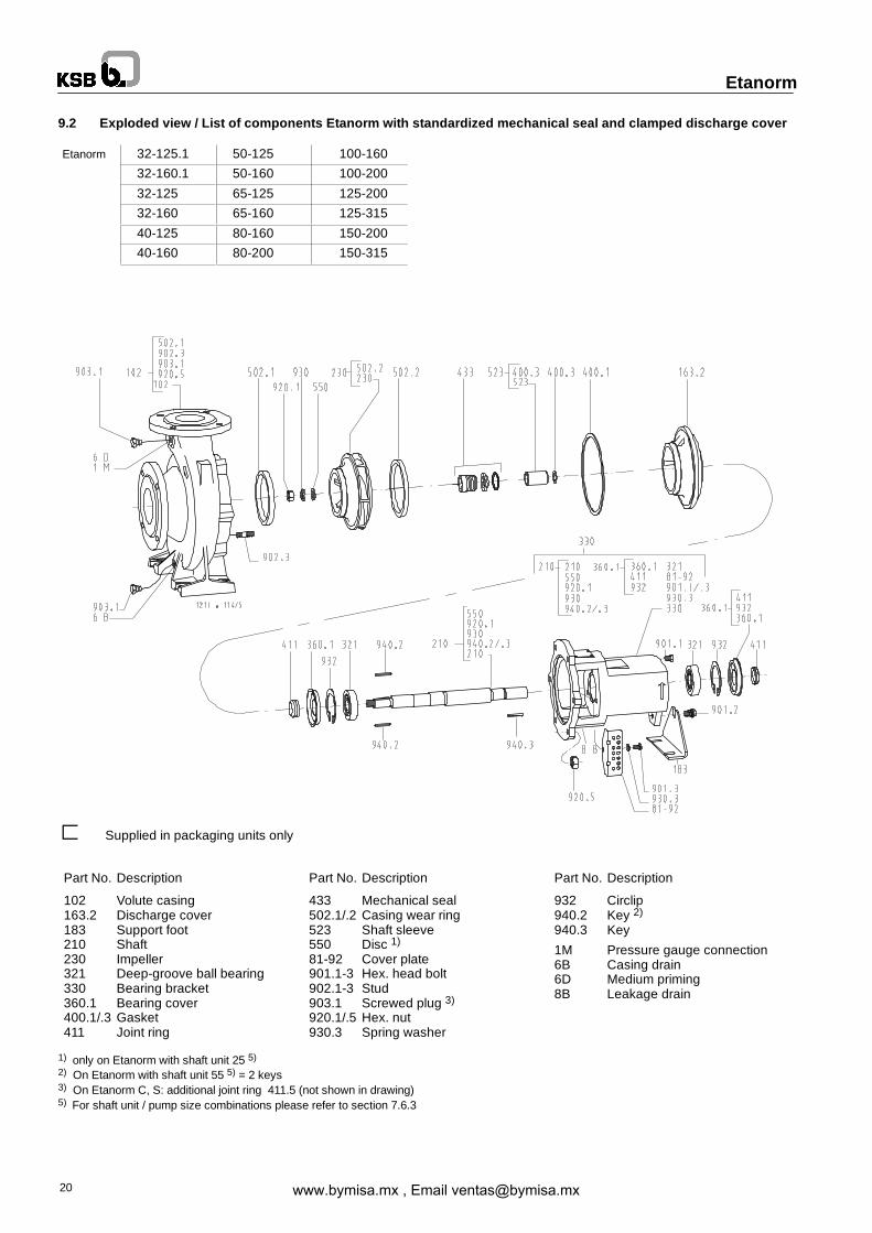
9.2 Exploded view / List of components Etanorm with standardized mechanical seal and clamped discharge cover
Etanorm 32-125.1 50-125 100-160
32-160.1 50-160 100-200
32-125 65-125 125-200
32-160 65-160 125-315
40-125 80-160 150-200
40-160 80-200 150-315
⊏ Supplied in packaging units only
Part No. Description Part No. Description Part No. Description
102 Volute casing163.2 Discharge cover183 Support foot210 Shaft230 Impeller321 Deep-groove ball bearing330 Bearing bracket360.1 Bearing cover400.1/.3 Gasket411 Joint ring
433 Mechanical seal502.1/.2 Casing wear ring523 Shaft sleeve550 Disc 1)
81-92 Cover plate901.1-3 Hex. head bolt902.1-3 Stud903.1 Screwed plug 3)
920.1/.5 Hex. nut930.3 Spring washer
932 Circlip940.2 Key 2)
940.3 Key
1M Pressure gauge connection6B Casing drain6D Medium priming8B Leakage drain
1) only on Etanorm with shaft unit 25 5)
2) On Etanorm with shaft unit 55 5) = 2 keys3) On Etanorm C, S: additional joint ring 411.5 (not shown in drawing)5) For shaft unit / pump size combinations please refer to section 7.6.3
www.bymisa.mx , Email [email protected]

Etanorm
21
9.3 Exploded view / List of components Etanorm with gland packing and bolted-on discharge cover
Etanorm 32-200.1 50-200 80-250 125-250
32-250.1 50-250 80-315 125-400
32-200 50-315 80-400 150-250
32-250 65-200 100-250 150-400
40-200 65-250 100-315
40-250 65-315 100-400
40-315
⊏ Supplied in packaging units only
Part No. Description Part No. Description Part No. Description
102 Volute casing163.1 Discharge cover183 Support foot210 Shaft230 Impeller321 Deep-groove ball bearing330 Bearing bracket360.1 Bearing cover400.1 Gasket411 Joint ring
452 Gland cover454 Stuffing box ring458 Lantern ring461 Gland packing502.1/.2 Casing wear ring524 Shaft protecting sleeve550 Disc 1)
81-92 Cover plate901.1-.3 Hex. head bolt902.1/.2/.4 Stud
903.1 Screwed plug 2)
920.1-.3 Hex. nut930.3 Spring washer932 Circlip940.1-.3 Key
1M Pressure gauge connection6B Casing drain6D Medium priming8B Leakage drain
1) only on Etanorm with shaft unit 25 5)
2) On Etanorm C, S: additional joint ring 411.5 (not shown in drawing)3) For shaft unit / pump size combinations please refer to section 7.6.3
www.bymisa.mx , Email [email protected]

1211:113/4
Etanorm
22
9.4 Exploded view / List of components Etanorm with gland packing and clamped discharge cover
Etanorm 32-125.1 50-125 100-160
32-160.1 50-160 100-200
32-125 65-125 125-200
32-160 65-160 125-315
40-125 80-160 150-200
40-160 80-200 150-315
⊏ Supplied in packaging units only
Part No. Description Part No. Description Part No. Description
102 Volute casing163.1 Discharge cover183 Support foot210 Shaft230 Impeller321 Deep-groove ball bearing330 Bearing bracket360.1 Bearing cover400.1 Gasket411 Joint ring 2)
452 Gland cover454 Stuffing box ring458 Lantern ring461 Gland packing502.1/.2 Casing wear ring524 Shaft protecting sleeve550 Disc 1)
81-92 Cover plate901.1-.3 Hex. head bolt902.3/.4 Stud
903.1 Screwed plug 2)
920.1 Hex. nut930.3 Spring washer932.1-.3 Circlip940.1-.3 Key
1M Pressure gauge connection6B Casing drain6D Medium priming8B Leakage drain
1) only on Etanorm with shaft unit 25 5)
2) On Etanorm C: additional joint ring 411 (not shown in drawing)3) For shaft unit / pump size combinations please refer to section 7.6.3
www.bymisa.mx , Email [email protected]
1211:172
B
Etanorm
23
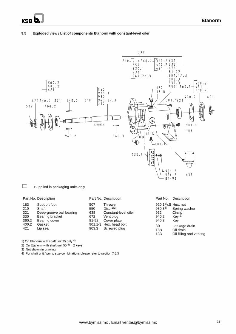
9.5 Exploded view / List of components Etanorm with constant-level oiler
⊏ Supplied in packaging units only
Part No. Description Part No. Description Part No. Description
183 Support foot210 Shaft321 Deep-groove ball bearing330 Bearing bracket360.2 Bearing cover400.2 Gasket421 Lip seal
507 Thrower550 Disc 1)3)
638 Constant-level oiler672 Vent plug81-92 Cover plate901.1-3 Hex. head bolt903.3 Screwed plug
920.13)/.5 Hex. nut930.33) Spring washer932 Circlip940.2 Key 2)
940.3 Key
8B Leakage drain13B Oil drain13D Oil-filling and venting
1) On Etanorm with shaft unit 25 only 4)
2) On Etanorm with shaft unit 55 4) = 2 keys3) Not shown in drawing4) For shaft unit / pump size combinations please refer to section 7.6.3
www.bymisa.mx , Email [email protected]