operating systems cmpsc 473
DESCRIPTION
Operating Systems CMPSC 473. I/O Management (3) December 07, 2010 - Lecture 24 Instructor: Bhuvan Urgaonkar. File System. Read Sectors. Write Sectors. Block Interface. Controller (FTL). RAM. Flash Memory. Flash Solid State Drive (SSD). Basics of NAND Flash Memory. Data. OOB. Page. - PowerPoint PPT PresentationTRANSCRIPT

Operating SystemsCMPSC 473I/O Management (3)
December 07, 2010 - Lecture 24Instructor: Bhuvan Urgaonkar

2
Flash Solid State Drive (SSD)
Controller(FTL)
RAM
Flash Memory
File System
Read Sectors Write Sectors
Block Interface

3
Basics of NAND Flash Memory
• Three operations: read, write, erase• Reads and writes are done at the granularity of a page (2KB or 4KB)• Erases are done at the granularity of a block
– Block: A collection of physically contiguous pages (64 or 128)– Block erase is the slowest operation requiring about 2ms
• Writes can only be done on erased pages
Page
Block
PagePage
Page
Data OOB
Block
……
PagePage
Page
Data OOB
Block
…………
NAND Flash
Page
Page
Data OOB
……Page
Page
Data OOB
……
PagePagePage

4
• Over-writes on the same location (page) are expensive
• Updates are written to a free page• OOB area
– Keeps valid/free/invalid status– Stores LPN, used to reconstruct mapping table
upon power failure
(0, 0)
Out-of-Place Updates
Block 0Flash Mapping Table
A
LPN PPN (PBN, Offset)
B (0, 1)C (0, 2)
(0, 3)AUpdate
Free
LPN=A, VLPN=B, VLPN=C, V
Data OOB Invalid
LPN=A, V

5
• Reclaims invalid pages
• Typically, called when free space falls below a threshold
• Victim block selection– Small # valid pages (reduce copying overhead)– Small # overall erases (wear level)
Garbage Collection
6
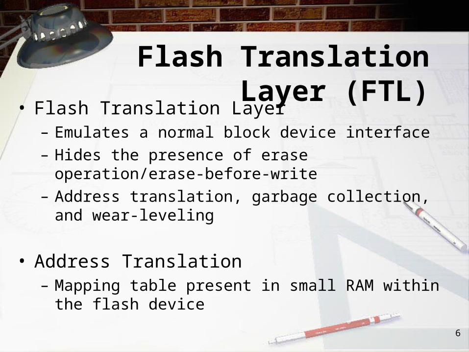
Flash Translation Layer (FTL)• Flash Translation Layer
– Emulates a normal block device interface– Hides the presence of erase operation/erase-
before-write– Address translation, garbage collection, and wear-
leveling
• Address Translation – Mapping table present in small RAM within the
flash device

Latencies compared

Cost• Main memory is much more expensive than disk
storage• The cost per megabyte of hard disk storage is
competitive with magnetic tape if only one tape is used per drive.
• The cheapest tape drives and the cheapest disk drives have had about the same storage capacity over the years.
• Tertiary storage gives a cost savings only when the number of cartridges is considerably larger than the number of drives.

Memory, Disk Price Trends Compared

Latency Relative Cost/GB
Lifetime
DRAM 55 ns (word) 30-40 10^16 reads/writes
NAND FlashSSD
40-50 us (read, page)200-250 us (write, page)2 ms (erase, block)
10-20 100K-1M erases/block
Magnetic disk 5 ms (seek time) 1 MTTF=1 Mhr

CPU/MemorySub-system
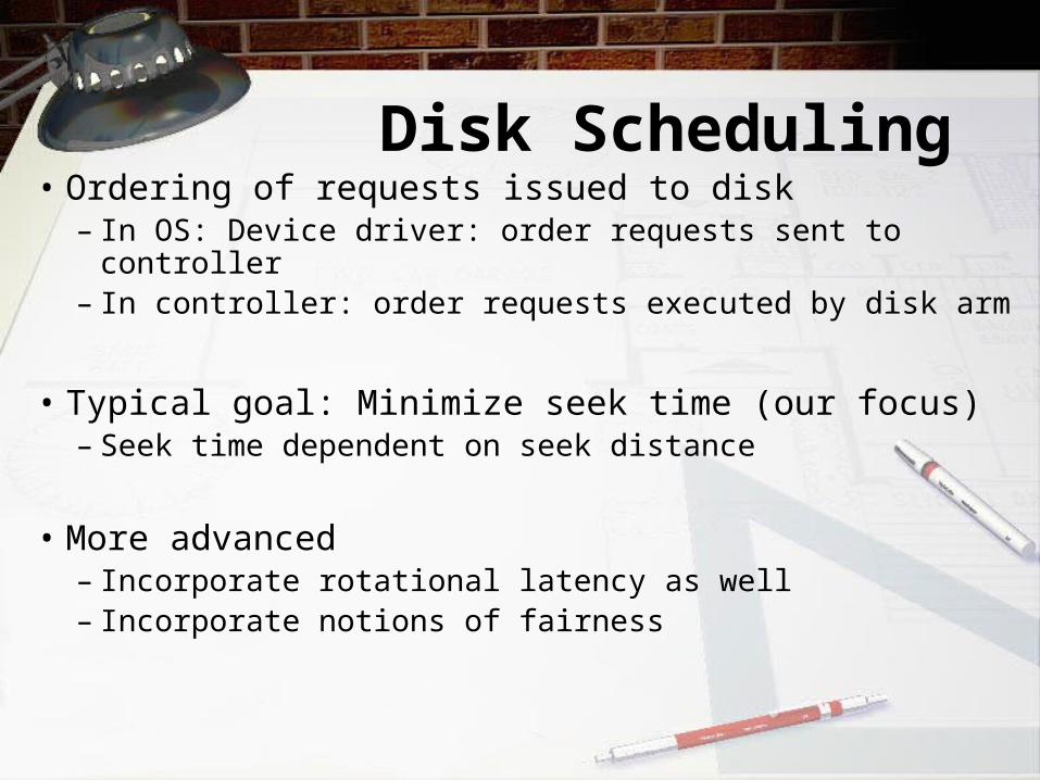
Disk Scheduling• Ordering of requests issued to disk
– In OS: Device driver: order requests sent to controller
– In controller: order requests executed by disk arm
• Typical goal: Minimize seek time (our focus)– Seek time dependent on seek distance
• More advanced– Incorporate rotational latency as well– Incorporate notions of fairness
Disk Scheduling (Cont.)
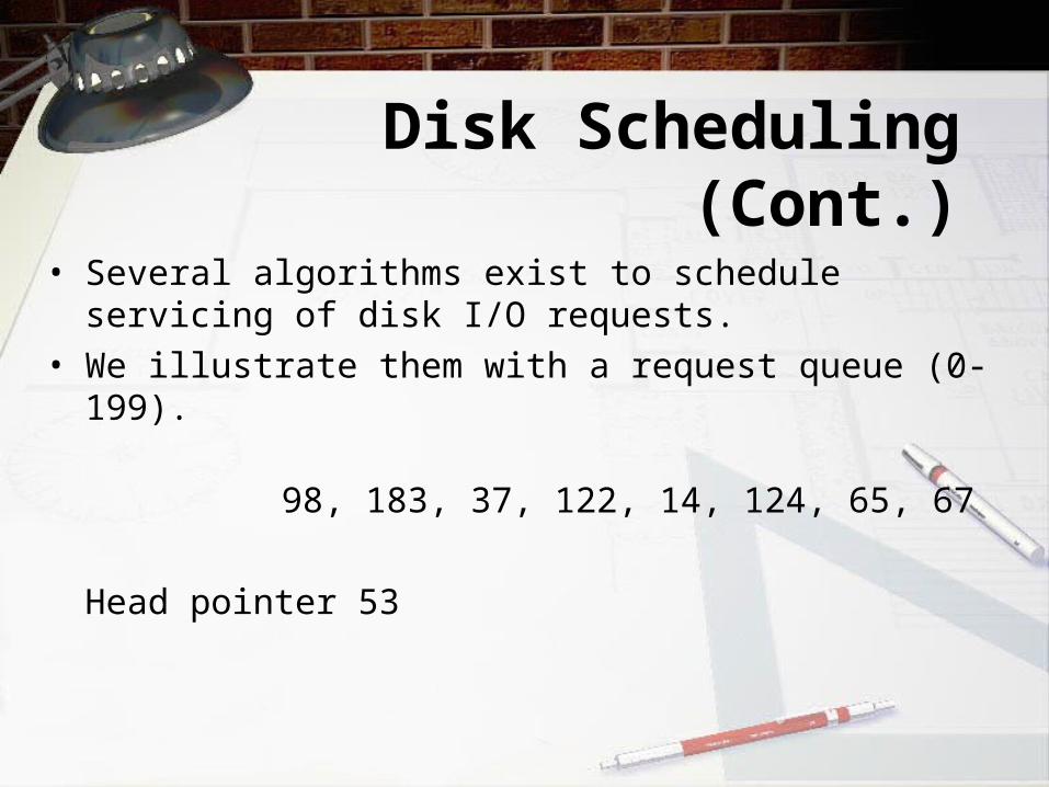
• Several algorithms exist to schedule servicing of disk I/O requests.
• We illustrate them with a request queue (0-199).
98, 183, 37, 122, 14, 124, 65, 67
Head pointer 53

FCFSIllustration shows total head movement of 640 cylinders.

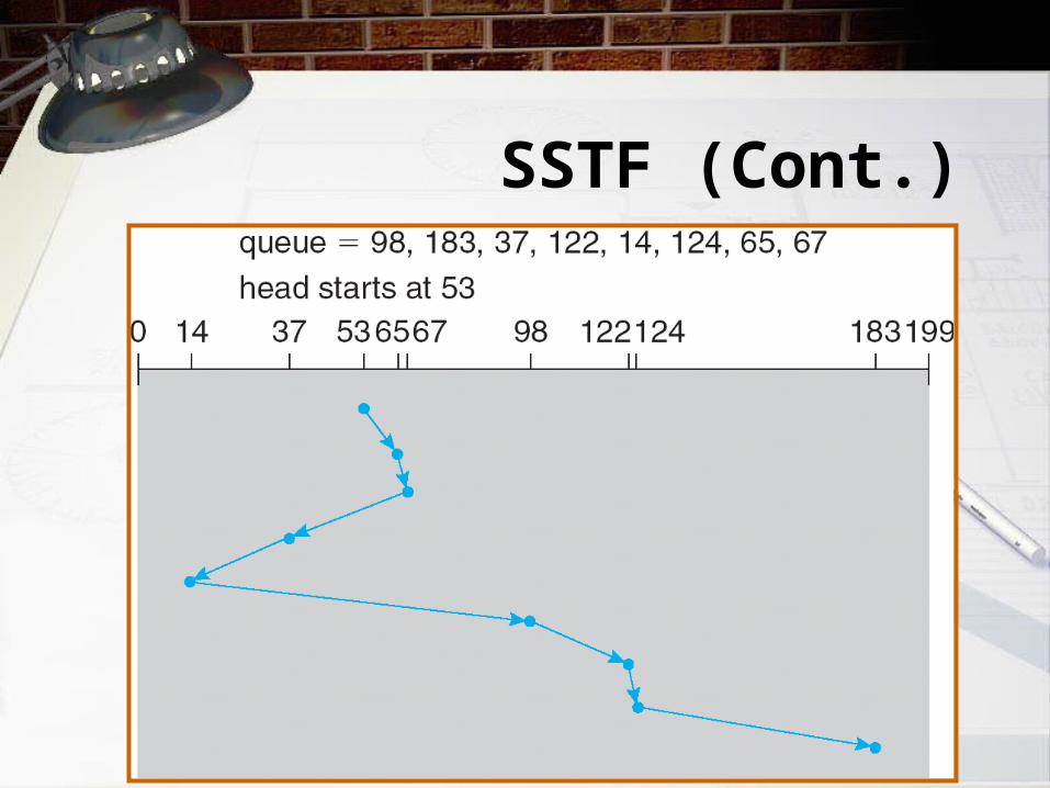
SSTF• Selects the request with the
minimum seek time from the current head position.
• SSTF scheduling is a form of SJF scheduling; may cause starvation of some requests.
• Illustration shows total head movement of 236 cylinders.
SSTF (Cont.)

SCAN• The disk arm starts at one end of the
disk, and moves toward the other end, servicing requests until it gets to the other end of the disk, where the head movement is reversed and servicing continues.
• Sometimes called the elevator algorithm.• Illustration shows total head movement
of 208 cylinders.

SCAN (Cont.)
C-SCAN• Provides a more uniform wait time than SCAN.• The head moves from one end of the disk to
the other. servicing requests as it goes. When it reaches the other end, however, it immediately returns to the beginning of the disk, without servicing any requests on the return trip.
• Treats the cylinders as a circular list that wraps around from the last cylinder to the first one.

C-SCAN (Cont.)
C-LOOK• Version of C-SCAN• Arm only goes as far as the last
request in each direction, then reverses direction immediately, without first going all the way to the end of the disk.

C-LOOK (Cont.)

File-System Structure
• File structure– Logical storage unit– Collection of related information
• File system resides on secondary storage (disks)
• File system organized into layers• File control block – storage structure
consisting of information about a file
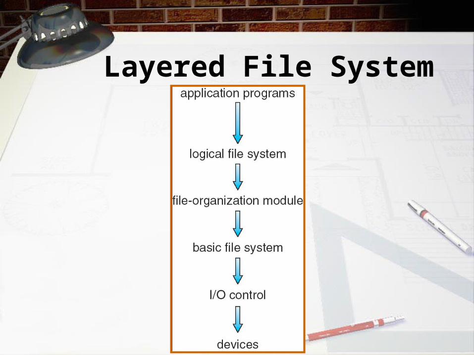
Layered File System

A Typical File Control Block

In-Memory FS Structures
• Opening a file
• Reading a file

File-System Structure
• File structure– Logical storage unit– Collection of related information
• File system resides on secondary storage (disks)
• File system organized into layers• File control block – storage structure
consisting of information about a file
Virtual File Systems
• Virtual File Systems (VFS) provide an object-oriented way of implementing file systems.
• VFS allows the same system call interface (the API) to be used for different types of file systems.
• The API is to the VFS interface, rather than any specific type of file system.
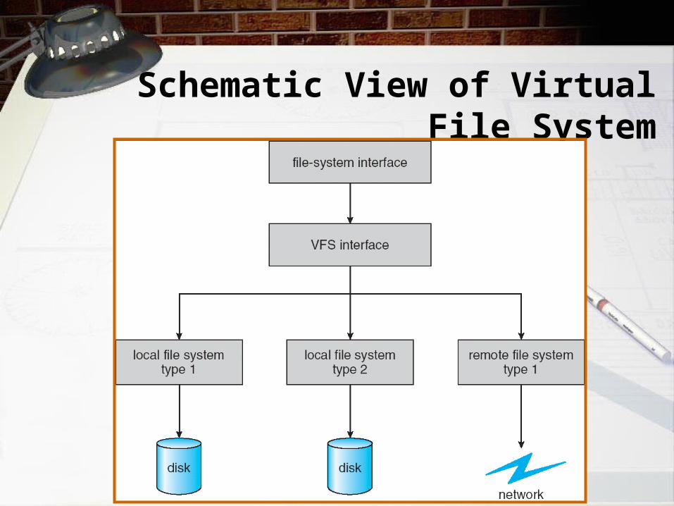
Schematic View of Virtual File System

Directory Implementation
• Linear list of file names with pointer to the data blocks.– simple to program– time-consuming to execute
• Hash Table – linear list with hash data structure.– decreases directory search time– collisions – situations where two file names hash to
the same location– fixed size
Allocation Methods• An allocation method refers to how disk
blocks are allocated for files:
• Contiguous allocation
• Linked allocation
• Indexed allocation
Contiguous Allocation• Each file occupies a set of contiguous blocks
on the disk
• Simple – only starting location (block #) and length (number of blocks) are required
• Wasteful of space (dynamic storage-allocation problem)
• Files cannot grow
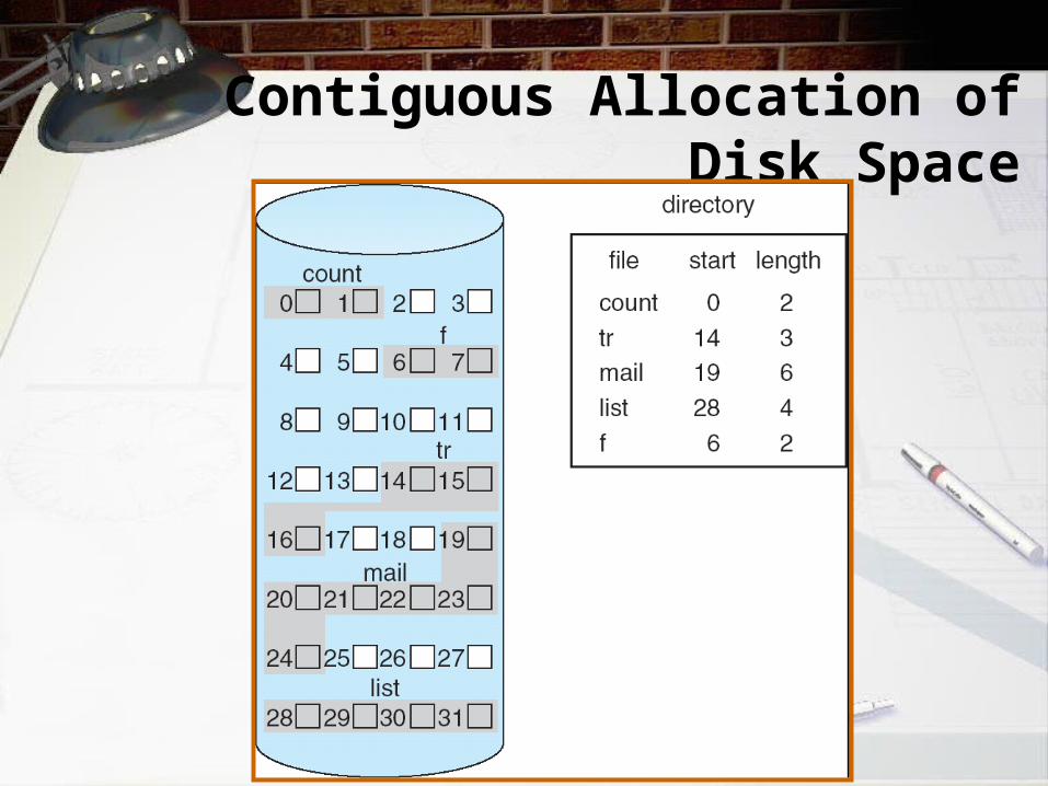
Contiguous Allocation of Disk Space
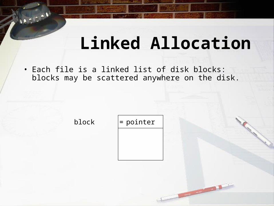
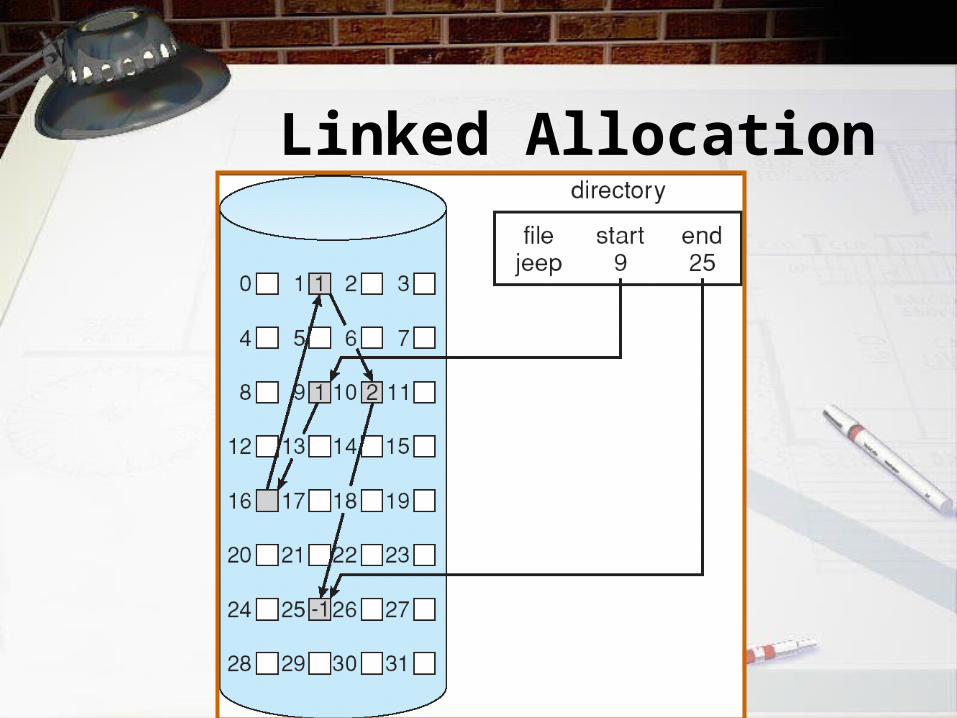
Linked Allocation• Each file is a linked list of disk blocks: blocks may be
scattered anywhere on the disk.
pointerblock =

Linked Allocation (Cont.)
• Simple – need only starting address• Free-space management system – no waste of
space • Mapping
Block to be accessed is the Qth block in the linked chain of blocks representing the file.Displacement into block = R + 4
File-allocation table (FAT) – disk-space allocation used by MS-DOS and OS/2.
LA/508Q
R
Linked Allocation

File-Allocation Table

Indexed Allocation• Brings all pointers together into the index block.• Logical view:
index table
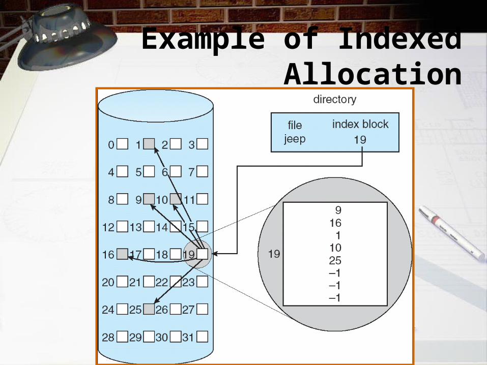
Example of Indexed Allocation
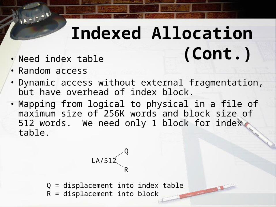
Indexed Allocation (Cont.)• Need index table
• Random access• Dynamic access without external fragmentation,
but have overhead of index block.• Mapping from logical to physical in a file of
maximum size of 256K words and block size of 512 words. We need only 1 block for index table.
LA/512Q
R
Q = displacement into index tableR = displacement into block

Indexed Allocation – Mapping (Cont.)
• Mapping from logical to physical in a file of unbounded length (block size of 512 words).
• Linked scheme – Link blocks of index table (no limit on size).
LA / (512 x 508)Q1
R1
Q1 = block of index tableR1 is used as follows:
R1 / 512Q2
R2
Q2 = displacement into block of index tableR2 displacement into block of file:

Indexed Allocation – Mapping (Cont.)
• Two-level index (maximum file size is 5123)
LA / (512 x 512)Q1
R1
Q1 = displacement into outer-indexR1 is used as follows:
R1 / 512Q2
R2
Q2 = displacement into block of index tableR2 displacement into block of file
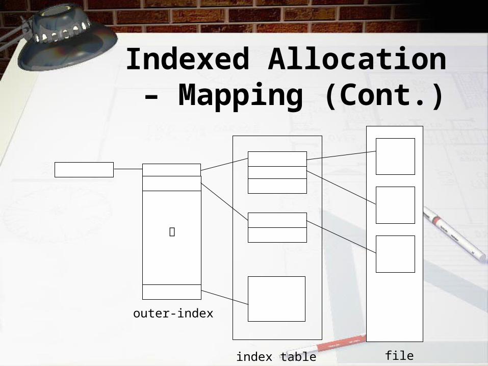
Indexed Allocation – Mapping (Cont.)
outer-index
index table file

Combined Scheme: UNIX (4K bytes per block)

Free-Space Management
• Bit vector (n blocks)
…
0 1 2 n-1
bit[i] = 0 block[i] free
1 block[i] occupied
Block number calculation
(number of bits per word) *(number of 0-value words) +offset of first 1 bit
Free-Space Management (Cont.)• Bit map requires extra space
– Example:block size = 212 bytesdisk size = 230 bytes (1 gigabyte)n = 230/212 = 218 bits (or 32K bytes)
• Easy to get contiguous files • Linked list (free list)
– Cannot get contiguous space easily– No waste of space

Linked Free Space List on Disk

Efficiency and Performance
• Efficiency dependent on:– disk allocation and directory algorithms– types of data kept in file’s directory entry
• Performance– disk cache – separate section of main memory for
frequently used blocks– free-behind and read-ahead – techniques to optimize
sequential access– improve PC performance by dedicating section of
memory as virtual disk, or RAM disk

Page Cache• A page cache caches pages rather than disk
blocks using virtual memory techniques
• Memory-mapped I/O uses a page cache
• Routine I/O through the file system uses the buffer (disk) cache
• This leads to the following figure

I/O W/O a Unified Buffer Cache
Unified Buffer Cache
• A unified buffer cache uses the same page cache to cache both memory-mapped pages and ordinary file system I/O

I/O Using a Unified Buffer Cache