operating manual - wagner werkzeugsysteme müller gmbh · 2 operating manual zr27-2 table of ......
TRANSCRIPT

Operating Manual
Thread Cutting Heads ZR 27-2
2 Operating Manual ZR27-2
Table of Contents
1. Preface 3
2. Security advice 5
3. Method of operation of the chaser head 6
4. Application 7
5. Using the chaser head 85.1. Functioning of the component parts of the chaser head 85.2. Description and coding of the chaser holders 95.3. Changing the chaser holders 95.4. Changing the chasers 10
6. The chasers 126.1. Chaser form 126.2. Coding of the chasers 136.3. Chaser grades 146.4. Grinding the chasers 14
7. Thread cutting 167.1. Setting the thread diameter 167.2. Faulty threads and their causes 167.3. Cooling 18
8. Tables 198.1. Instructions for the use of the setting tables 198.2. Setting Tables for ZR 27 die head 208.3. Instructions for using the table of chaser holders 228.4. Table of chaser holders for types ZA/ ZR 27 Die Heads 238.5. Selecting the top rake 238.6. Calculating the grinding angle 238.7. Calculating the cutting speed 24
9. Spare parts for thread cutting head ZR27-2 29
10. Single Parts for the die head with special detent ZR 27-AR 32
11. Mounting of die heads ZR 27-2 33
12. R 27-2 zum Einstechen 3412.1. Mounting and control chart 0.0360-199 3412.2. Mounting chart 0.0360-205 35
Operating Manual ZR27-2 3
Preface
1. Preface
Dear customer,
you purchased a high-quality technical tool which guarantees you an efficient work performance.The cutting heads of our company are widely known for their high quality and long-life cycle.We do hope that you are perfectly satisfied with our products, too.
Customer care even after purchase:This operating manual helps you to make the first steps with the new WAGNER® pro-duct. It helps to understand its Function and alludes to possible hazards.
However, should you be in need of further consulting service, training or some other advice do not hesitate to contact us.Even if you are not happy with one of our WAGNER® products!Our marketing staff is more than glad to help you at anytime.
This operating manual should be read, understood and paid attention to by every person in charge.In particularly this applies for safety- and hazard warnings which are specially indi-cated. (See chapter 2.0 safety warnings)Following these advices helps to avoid accidents and faults.
This manual provides all information on operation and maintenance of your WAG-NER® Thread cutting head. The information laid down in this manual is state of the art according to the production date of the product.
Please use only this manual when working with the thread cutting head. The WAG-NER® Werkzeugsysteme Müller GmbH reserves the right to technical amendments re-garding the improvement of this product. However, the WAGNER® Werkzeugsyteme Müller GmbH cannot held liable for any faults, damages, failures and production loss resulting thereof caused by disregarding of some aspects mentioned in this manual.
Due to copyright reasons we would like to point out that this operating manual is for internal use only. Please refrain from distributing it to third parties.In addition to the instructions mentioned before, national and international „safety in-structions and rules for accident prevention“ apply when operating and maintaining the cutting head. The operating manual, in particular, the „safety instructions“ have to be read carefully. Through observing the safety instructions and legal regulations damage to persons, mechanical breakdown and damage to the cutting head should be avoided.
WarrantyWe warrant perfect function of the thread cutting heads when purchasing and using original WAGNER® spare parts and equipment.We cannot hold liable for any damage to persons, mechanical breakdown and da-mage to the thread cutting head ZR 22-2 in the event of: • Improper installation and operation• Usage of non original spare parts• Removal of component parts and screws• Unauthorised modifications of our products • Usage of damaged cutting heads.
Please note: Read this operating manual carefully before initial ope-ration and take note of the hazard warnings!

4 Operating Manual ZR27-2
Preface
We cannot hold liable for any use of components which are not manufactured or not approved by WAGNER®.We cannot hold liable for damages occurring through removing of safety devices of the machine. We imply the placing into operation of our products on efficient tech-nical machines.
Normal use:Don’t use force when mounting, dismounting and operating the cutting head. Other-wise you will cause damages to the cutting head or the machine.
Initial operationCheck the function of the thread cutting head before initial operation.
Limitation of liability: Please note: Use this product
only for the purpose it is manufactured for!
Please take notice of the sa-fety instructions and hazard
warnings! The thread cutting head ZR 22-2 should only be used by trained techni-cal staff. Otherwise health
hazard or danger of life and damage to property cannot
be ruled out. In that case we cannot hold liable for any of
these damages.

Operating Manual ZR27-2 5
Security advice
2. Security advice
• Persons operating, maintaining or servicing the cutting head should always read and understand the operating manual in particular the safety inst-ructions. Persons under the influence of alcohol and /or drugs may cause accidents!
• Take into account the weight of the thread cutting head upon installation. If necessary lift it with a lifting gear.
• Please take note that the cutting sites between tool and machine are kept clean. Should they be fouled the accuracy of the workpiece is affected.
• When installing the tools switch off the machine at the line switch. When changing the chaser holders and chasers take note that the tool shaft isn’t starting unexpectedly.
• Remove all tools and testing equipment from the workspace of the machine before activating it. Risk of injury arises through tools and testing equip-ment which are flung about!
• Close guard door or protection case before machining. Flying chipping and damaged tools or workpieces can cause damage to persons or mechanical breakdown.
• Make sure that the thread cutting head isn’t loosening when machining.
• Don’t touch the cutting head upon closing. Don’t touch rotating tools: Risk of injury!
• Be very careful when dealing with the chasers. The edges of the chasers are very sharp. Wear safety gloves if necessary!
• Please ensure that the thread cutting head is properly secured and attached whilst transporting.

6 Operating Manual ZR27-2
Method of operation of the chaser head
3. Method of operation of the chaser head
This head is of a specially small design and is intended for applications where lack of space prevents the use of the standard Z-type head. This fact must be taken into account when apportioning the work.The chaser head incorporates four tangential chasers. A series of chaser holders is provided to enable a large operating range and close adaption of the chaser position to the thread pitch to be achieved. In this way, the operating accuracy is suited to the degree of accuracy required by fine threads. Opening and closing of the head is con-trolled by a carrier mechanism. In its most simple form, the mechanism is actuated by hand, but it can also be modified for automatic operation.
Operating Manual ZR27-2 7
Application
4. Application
Cutting parallel external threadsAll external threads listed in the table of chaser holders can be cut.
Cutting of taper external threadsTaper threads with a taper angle not exceeding 1:16 can be plunge-cut if the thread length including the chamfer is less than the width of the chaser. The stresses impo-sed on the head are large, and this method can therefore only be employed for fine threads on a continuous basis. Taper threads cut in this way have four slight axial chaser marks which cannot be avoided.
Cutting left-hand threadsLeft-hand threads can be produced without difficulty with the same chaser head by rotating the main spindle in the anti-clockwise direction. However, left-hand holders and left-hand chasers will be required.
Skin turning boltsWe can supply skin turning tools whose external design is similar to that of the chaser jaws, except for the absence of thread profiles. The guide teeth are replaced by a wear surface which prevents the cutting edge from digging into the workpiece. Tools of this type can be used to size bolts at low cutting speeds.Where higher cutting speeds and greater outputs are desired, the use of a WAG-NER® skin turning machine is recommended. The tungsten carbide tools of such a machine result in greatly reduced operating periods.
Use on other machinesA carrier mechanism must be fitted to the head of it is to be used on other machines. This mechanism can be actuated with the carrier [32] which is available on request.

8 Operating Manual ZR27-2
Using the chaser head
5. Using the chaser head
5.1. Functioning of the component parts of the chaser head
The chaser head comprises four main groups
The head bodyThe die head [1] is attached to the main spindle by the four cheese-head screws [10]. The sliding key [9] attached to the die head with the countersunk screw [7] pro-jects into the spindle flange, thus providing the necessary power transmission. The spring-loaded bushes [3]‘, together with the springs [4], press the holders outwards. This movement is limited by the shoulder studs [5]. The axial movement of the guide ring [8] is limited by the stop pin [17] pressed into the recess of the guide ring by the spring [16]. The cheese-head screw [18] prevents the stop pin from falling out. The spring-loaded ball catch projecting from the sliding key [9] prevents accidental retraction of the die ring when the head is closed.
The die ringThe cam ring [2] and the guide ring [8] are connected by the plates [11] and Allen screws [12]. The unit formed in this way is referred to as the "die ring". As the keyway of the guide ring slides on the key [9], the die ring can only be moved axially in relati-on to the die head to the extent permitted by the stop pin [17] in conjunction with the recess. The die ring can only be withdrawn after depressing the stop pin [17] with the handle of the taper key [29] inserted through the hole in the guide ring [8]. The cam ring can be rotated against the guide ring with the taper key inserted into the hole [p], after slackening the countersunk screws [13] or the Allen screws [12].
The carrier ringThis controls the axial movement of the die ring. The carrier dogs [26] mounted on the carrier with the two screws [33] engage in the circular groove of the guide ring [8], thus controlling the movement of the die ring even when the head is rotating.
The holdersThe chaser holders are swivel-mounted in the die head, their axial position being maintained by the register of the die head. The holders are supported against the cam ring by the sliding blocks [24].
Figure 1: The head body
Operating Manual ZR27-2 9
Using the chaser head
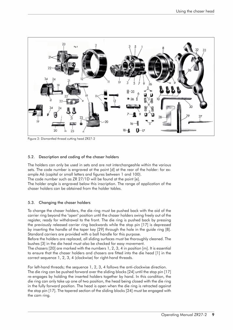
5.2. Description and coding of the chaser holders
The holders can only be used in sets and are not interchangeahle within the various sets. The code number is engraved at the point [d] at the rear of the holder: for ex-ample A6 (capital or small letters and figures between 1 and 100).The code number such as ZR 27/1D will be found at the point [e].The holder angle is engraved below this inscription. The range of application of the chaser holders can be obtained from the holder tables.
5.3. Changing the chaser holders
To change the chaser holders, the die ring must be pushed back with the aid of the carrier ring beyond the "open" position until the chaser holders swing freely out of the register, ready for withdrawal to the front. The die ring is pushed back by pressing the previously released carrier ring backwards while the stop pin [17] is depressed by inserting the handle of the taper key [29] through the hole in the guide ring [8]. Standard carriers are provided with a ball handle for this purpose.Before the holders are replaced, all sliding surfaces must be thoroughly cleaned. The bushes [3] in the die head must also be checked for easy movement.The chasers [20] are marked with the numbers 1, 2, 3, 4 in position [m]. It is essential to ensure that the chaser holders and chasers are fitted into the die head [1] in the correct sequence 1, 2, 3, 4 (clockwise) for right-hand threads.
For left-hand threads; the sequence 1, 2, 3, 4 follows the anti-clockwise direction. The die ring can be pushed forward over the sliding blocks [24] until the stop pin [17] re-engages by holding the inserted holders together by hand. In this condition, the die ring can only take up one of two position, the head being closed with the die ring in the fully forward position. The head is open when the die ring is retracted against the stop pin [17]. The tapered section of the sliding blocks [24] must be engaged with the cam ring.
Figure 2: Dismantled thread cutting head ZR27-2
10 Operating Manual ZR27-2
Using the chaser head
5.4. Changing the chasers
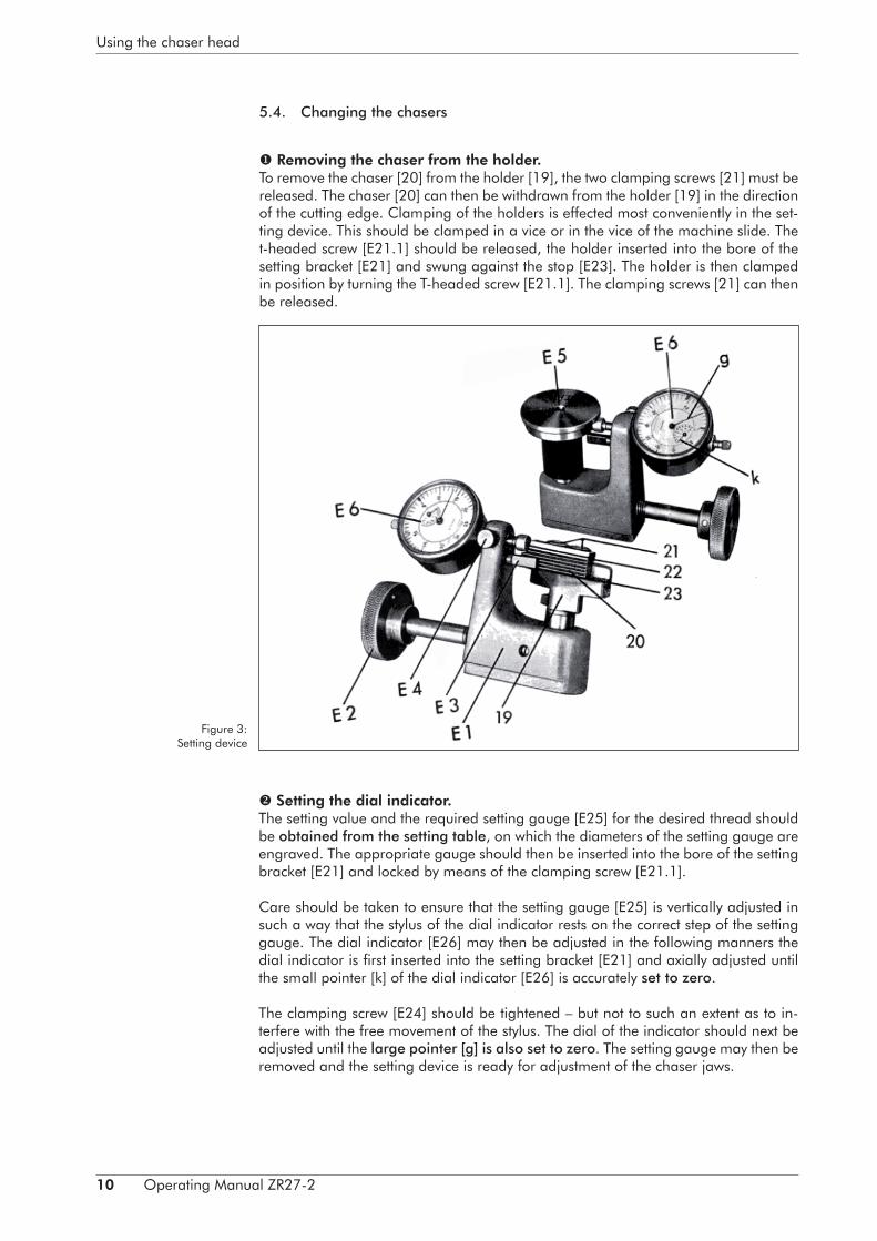
Removing the chaser from the holder. To remove the chaser [20] from the holder [19], the two clamping screws [21] must be released. The chaser [20] can then be withdrawn from the holder [19] in the direction of the cutting edge. Clamping of the holders is effected most conveniently in the set-ting device. This should be clamped in a vice or in the vice of the machine slide. The t-headed screw [E21.1] should be released, the holder inserted into the bore of the setting bracket [E21] and swung against the stop [E23]. The holder is then clamped in position by turning the T-headed screw [E21.1]. The clamping screws [21] can then be released.
Figure 3: Setting device
Setting the dial indicator. The setting value and the required setting gauge [E25] for the desired thread should be obtained from the setting table, on which the diameters of the setting gauge are engraved. The appropriate gauge should then be inserted into the bore of the setting bracket [E21] and locked by means of the clamping screw [E21.1].
Care should be taken to ensure that the setting gauge [E25] is vertically adjusted in such a way that the stylus of the dial indicator rests on the correct step of the setting gauge. The dial indicator [E26] may then be adjusted in the following manners the dial indicator is first inserted into the setting bracket [E21] and axially adjusted until the small pointer [k] of the dial indicator [E26] is accurately set to zero.
The clamping screw [E24] should be tightened – but not to such an extent as to in-terfere with the free movement of the stylus. The dial of the indicator should next be adjusted until the large pointer [g] is also set to zero. The setting gauge may then be removed and the setting device is ready for adjustment of the chaser jaws.

Operating Manual ZR27-2 11
Using the chaser head
Setting the chaser in the holder.In place of the setting gauge [E25], the carefully cleaned holder [19] is now inserted into the setting bracket [E21]. The clamping plate [22], the clamping screws [21] and the adjusting screw [23] should already have been released.The chaser [20] should then be inserted into the holder.
The holder is swung against the stop [E23] while the measuring pin cf the dial indica-tor is retracted. The vertical rrsitlon of the chaser holder and the chaser will he correct if the stylus of the dial gauge rests against the point of the last cutting tooth or moves closely along the side surface of the guide teeth. The chaser must of course never be clamped in a position high enough to cause the stylus to touch the guide teeth.The holder should be clamped by means of the T-headed screw [E21.1], and the clamping screws [21] should be lightly tightened. The chaser may then be adjusted by means of the setting screw [23] until the dial indicator shows the value quoted for the setting in the tables. (For theoretical setting values, setting above or below centre, see explanations to the setting table – Figure 4).
Figure 4: Setting the chaser in the holder
It is essential to ensure that both the small pointer [k] indicating millimetres, and the large pointer [g] indicating hundredths of one millimetre, correspond to the appro-priate setting value.
For example, if it is desired to set a value of 1.75, the small hand music be positioned between 1 and 2 and the large hand on 75.
The clamping screws [21] may then be tightened, the front clamping screw being tightened first to prevent distortion. It is recommended that the setting screw [23] should subsequently be firmly tightened. If the chaser is worn to such an extent that the clamping plate [22] is in danger of being distorted when the clamping screws [21] are tightened, the packing piece [25] must be inserted. This packing piece has the profile of the chaser dovetail and can be supplied in various lengths.
Having been adjusted, the chaser is now ready for use and the holder can be remo-ved from the setting device.

12 Operating Manual ZR27-2
The chasers
6. The chasers
6.1. Chaser form
The chasers cut tangentially and their main advantage in relation to radial tools is the fact that the front edges of each chaser can be re-ground as often as desired. To clarify the geometrical form of the chaser, it is shown in three views in Fig. 5, and in two vies in Fig. 4, which are so selected that the front edge of the chaser appears as a straight line. Fig. 4 shows how a clearance or relief angle may be produced by changing the setting value.
The teeth directly conversed in the thread cutting process are called cutting teeth and the following teeth are known as guide teeth. During re-sharpening which should only take place on the front face of the cutting teeth, special care must be taken to ensure that the side face of the guide teeth is not touched, since this face must always coincide with a gap between the successive thread flanks if clear and uniform threads are to be obtained. The first cutting teeth are chamfered to enable the chaser to bite into the material. This is shown in Fig. 5.
Figure 5: Chaser throats
These first teeth represent the throat. The first full cutting tooth completes the cutting of the thread. The subsequent guide teeth engage in the thread alrea-dy cut and provide the desired pitch spacing, thus dispensing with the need for a leadscrew in many cases. The chasers can be supplied with 3 different throats:
A long throat is used for black material and oversize components; the chaser takes the excess material off the workpiece.
A medium throat should be used whenever possible, but its use presuppo-ses that accurately sized material is being threaded.
A short throat should only be used if the medium throat is unsuitable due to its long run-out length, as for instance when threading close to a shoulder.
The working life of chasers having a short throat is somewhat less than that of chasers having a medium throat. Great care must be taken to prevent the side face of the chaser from running against a workpiece having an excessive diameter.

Operating Manual ZR27-2 13
The chasers
The guide length [f], that is to say the length by which the guide teeth are longer than the first full cutting tooth, should be maintained during successive re-grinds exactly as in the new chaser supplied by our works.If the guide teeth are too long it may happen that the chasers touch each other, par-ticularly when cutting small thread diameters, thus making it impossible to close the head, If the guide teeth are too short they do not provide sufficient guiding action for cutting the subsequent threads.
6.2. Coding of the chasers
In the same way as the holders, the chasers can also only be used in sets of four. Each set is marked with the same code number. This number is engraved on the rear of the chaser at the point [i]. The chaser number 1 to 4 is to be found on the front surface at the point [m]. These numbers should correspond with the holder numbers 1 to 4 when these are placed in position as already mentioned.
In addition, a standard thread is quoted, such as M 10 metric having a pitch of 1.5 mm. This enables metric threads having a pitch of 1.5 to be cut, for example M24x1.5; it should be remembered however that the corresponding chaser holder will be required (see holder table). Chasers marked ½“ (½ in. Whitworth thread (B.S.W.) having a pitch of 12 t.p.i.) can be used for cutting all B.S.F. threads having a pitch of 1/12 in., for example ¾ in. diameter x 12 t.p.i.
Figure 6: Description of the chasers
Chasers
cutting teeth
guide teeth
All chasers other than the V-thread type (for example Acme, knuckle and other spe-cial threads) are engraved with the angle 20 at the point [q] (see Fig. 6), to enable the grinding angle to be calculated (see chapter 9.6 on page 24).
The markings at point [n] refer to the type of steel used, for example B 32 or B 37. The numbers following the steel code are works reference numbers.
14 Operating Manual ZR27-2
The chasers
6.3. Chaser grades
The chasers can be supplied in two qualities:Quality B 32 is the standard grade suitable for maximum continuous output when cutting threads on easily machinable material having a tensile strength of up to 85 kg/mm (55 tons/sq.in.)Quality B 37 is suitable for material having a high tensile strength or poor machi-nability. This grade of chaser is only supplied on special request.
6.4. Grinding the chasers
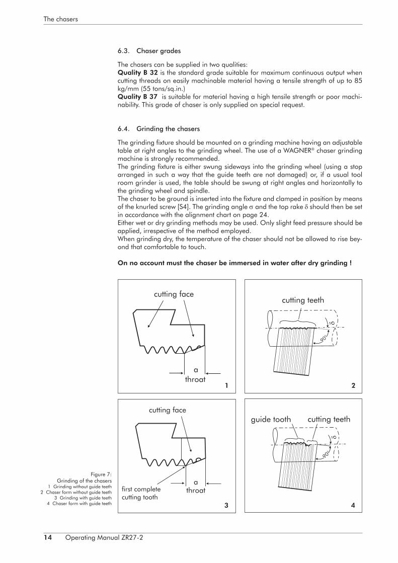
The grinding fixture should be mounted on a grinding machine having an adjustable table at right angles to the grinding wheel. The use of a WAGNER® chaser grinding machine is strongly recommended.The grinding fixture is either swung sideways into the grinding wheel (using a stop arranged in such a way that the guide teeth are not damaged) or, if a usual tool room grinder is used, the table should be swung at right angles and horizontally to the grinding wheel and spindle.The chaser to be ground is inserted into the fixture and clamped in position by means of the knurled screw [S4]. The grinding angle and the top rake should then be set in accordance with the alignment chart on page 24. Either wet or dry grinding methods may be used. Only slight feed pressure should be applied, irrespective of the method employed.When grinding dry, the temperature of the chaser should not be allowed to rise bey-ond that comfortable to touch.
On no account must the chaser be immersed in water after dry grinding !
Figure 7: Grinding of the chasers
1 Grinding without guide teeth2 Chaser form without guide teeth
3 Grinding with guide teeth4 Chaser form with guide teeth
first complete cutting tooth
1 2
3 4

Operating Manual ZR27-2 15
The chasers
For wet grinding, a powerful jet of coolant should be directed at the cutting edge. An adequate amount of coolant should be used to protect the chaser from dama-ge.(A rust inhibitor should be added to aqueous coolants.)Failure to observe the :e precautions may lead to the appearance of hairline cracks which cannot be observed with the naked eye, but which will eventually lead to failure through cracking of the chaser.Grinding wheels having a grain size of between 46 and 60 and a hardness of K or L are recommended for this purpose.
16 Operating Manual ZR27-2
Thread cutting
7. Thread cutting
7.1. Setting the thread diameter
Setting up of the head is greatly facilitated if a sample thread is available. The fol-lowing procedure should be adopted: the hexagon nuts of the countersunk screws [13] or the socket screws [12] should be released to enable the cam ring [2] to be adjusted. Adjustment of the cam ring is effected by means of the taper key [29] which is inserted into the aperture [p].Clockwise rotation of the key will close the head still further. The adjustment is, of course carried out with the head closed, so that the specimen thread held between the chasers can just be rotated. The trial thread may be cut after re-tightening the countersunk screws [13] of the socket screws [12]. The chaser die head is fitted with a special detent which surely prevents an unintentional displacement of the cam ring into circumferential direction in came of a sudden change of the turning direction. Before the cam ring is adjusted the inserted toothed segment [35] should always be removed by means of the taper key. After adjusting the desired thread diameter of the various delivered toothed segments this segment has to be inserted which is suiting in the best way to the tooth system of the cam ring in the new position. The use of an Aggra thread gauge, thread micromenter, gauge nut or other means will indicate the need for further adjustment. An adjustment of one scale division in 27 heads is equivalent to a change in diameter of approximately 0.18 mm (0.0070 in.).If no spezimen thread is available, a pin whose diameter corresponds to that of the core diameter of the thread may be uses for setting up the head.
7.2. Faulty threads and their causes
Faulty threads may be produced for a number of reasons:
• The correct numerical sequence from 1 to 4 of the chaser holders has not been observed. This results in a completely distorted thread or (if the holders are inser-ted in the reverse order 4, 3, 2, 1) no thread at all.
• Chasers from different sets may have been used. In this case the precise amount of offset between the chasers will not be achieved, thus resulting in a faulty th-read.
• The wrong set of chasers may have been inserted. For example it is impossible to produce a parallel thread with chasers for taper threads.
• The wrong setting value or grinding angle may have been selected. This may result in the appearance of shallow, thin threads whose roots are goo wide and whose flank angle is too small.
• Faulty threads may be produced although the mistakes mentioned above were not made, for example if the material requires other setting values or other grin-ding angles and top rakes than those provided.
The next pages list a number of defects and their remedies.

Operating Manual ZR27-2 17
Thread cutting
Defect Causes:
1. The thread is not concen-tric
The four chasers are not adjusted to the same set-ting value.The setting value is too small. The material is not concentric or is sheared off out of true. The cutting speed is too low. The top rake is too large. The guide length f is too short.
2. The pitch is faulty. The pitch angle of the holder is incorrect.The wrong holder is used.The wrong chasers are used (for example, a Tr 16x4 thread is being cut with Tr 14x4 chasers. The grinding angle is not correct.The setting value has not been adhered to.The feed pressure is too high.The feed pressure is too low or the slide offers too much resistance.
3. Wrong flank angle The chaser is not squarely mounted in the holder (check the clamping plates and the clamping sur-face of the chaser).
4. The thread is too shallow The grinding angle is too small or even negative.The setting value is too small.The top rake is too small.
5. The threads are of poor quality, the flank surfaces are rough.
This defect can be due to the formation of a double cutting edge which is often caused by selecting too small a top rake.The chaser is blunt.The cutting speed is too high.The coolant is unsuitable.
6. Continuous score marks on the flanks of the thread.
The offset is wrong.The chasers are not mounted in the corresponding holders. The guide teeth do not engage properly with the already cut thread. The chaser is broken or mount.
7. Chatter marks on the th-reads.
The setting value is too small. The speed is too high. The workpiece is clamped with excessive overhang. The top rake is to small for soft material.
8. The thread is eccentric in relation to the centreline of the material.
The material is not clamped concentrically.The slideways are no longer square to the thread i.e. to the axis of the head.

18 Operating Manual ZR27-2
Thread cutting
9. Multiple threads are gene-rated.
The chasers are not mounted in the correct se-quence.Heavy feed pressure may result in the production of multiple-start threads when cutting fine threads of a comparatively large diameter. The chaser will then automatically continue to cut these multiple threads.
10. The chaser jaws are bro-ken.
The diameter of the material is too large.The material is not concentric or is sheared off out of true.The setting value is too small.The speed is too low.
7.3. Cooling
Normally, thread cutting should only be carried out with the aid of a supply of coolant.Water soluble drilling oil can be used, but cutting oil is to be preferred if it is desired to produce clean threads.This will also considerably increase the working life of the chasers.
Operating Manual ZR27-2 19
Tables
8. Tables
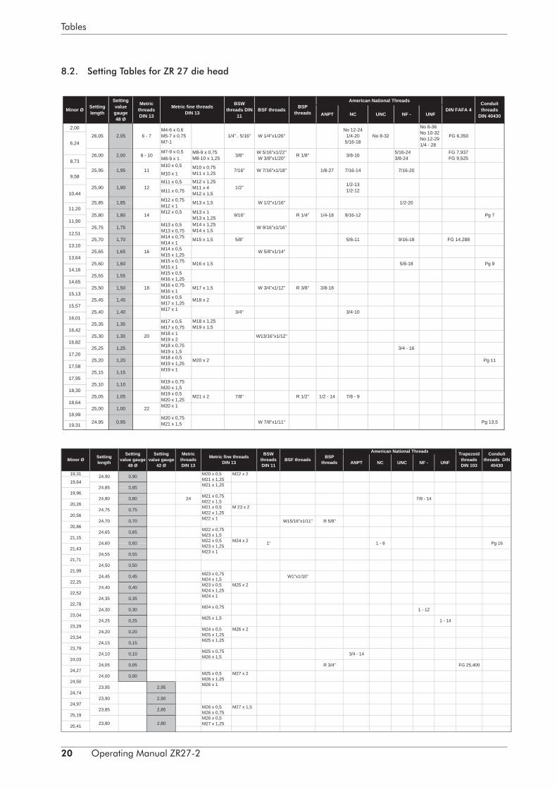
8.1. Instructions for the use of the setting tables
To ensure that the chasers are uniformly see in the correct relationship to the workpi-ece, they are adjusted in a setting device by means of a dial indicator. An accuracy of a few hundredths of a millimetre may be considered adequate. The desired values can be obtained from the setting table to an accuracy of 0.05 mm. The top row lists a large variety of customary threads. Since the setting value depends on the minor thread diameter, this is listed in the first column. The second solemn gives the setting length. This is the dimension between the point of contact of the chaser with the workpiece (assuming that the chaser is accurately set to the centreline of the workpiece) and the centreline of the holder pin. By subtracting half the diameter of the setting gauge from the setting length, the set-ting values listed in the third and fourth columns are obtained. It is immaterial which of the two steps of the setting gauge is used. In general however it is recommended that the step with the larger diameter be used, as this provides the smaller setting value. This facilitates counting the full millimetres as rotations of the large hand of the dial indicator.
To determine the setting value of a thread not listed in these tables, it is merely ne-cessary to know the minor diameter. This minor diameter should be interpolated in the appropriate posi-tion in the first column; the setting length and the setting value will thin be found in adjacent positions in the second and third columns respectively.
The values thus obtained provide a setting in which the cutting edge of the chaser is accurately positioned along the centreline of the workpiece. How-ever, this setting does not always result in the production of good threads.
It will often be necessary to select a slightly larger value (see Fig. 4 on page 11).When cutting threads in soft material it will be necessary to place the cutting edge beyond the centreline of the workpiece. In other words, the setting value must be in-creased if the threads produced with the normal setting value are not fully concentric. It is recommended that the value be initially increased by only 1%. Further adjustment of the chaser may be required if this does not produce the desired results.
Depending on the type of thread to be cut end material used, it may be necessary to increase the value by as much as 3 % of the diameter. In affecting these adjustments it must be remembered that the cutting temperature is always increased if the chaser acts at a point beyond the centreline of the workpiece. The setting value should there-fore not be increased more than absolutely necessary to produce the desired clean threads.
20 Operating Manual ZR27-2
Tables
8.2. Setting Tables for ZR 27 die head
ANPT NC UNC NF - UNF
2,00
M7-9 x 0,5 M8-9 x 1 . M10 x 0,5
M10 x 1
M11 x 0,5
M11 x 0,75
M12 x 0,75M12 x 1M12 x 0,5
M13 x 0,5 M13 x 0,75M14 x 0,75M14 x 1M14 x 0,5M15 x 1,25M15 x 0,75 M15 x 1 M15 x 0,5 M16 x 1,25M16 x 0,75M16 x 1M16 x 0,5M17 x 1,25M17 x 1
M17 x 0,5 M17 x 0,75 M18 x 1M19 x 2M18 x 0,75M19 x 1,5M18 x 0,5M19 x 1,25M19 x 1
M19 x 0,75M20 x 1,5M19 x 0,5 M20 x 1,25M20 x 1
M20 x 0,75M21 x 1,5
Pg 7
Pg 13,50,95 W 7/8"x1/11"24,95
M4-6 x 0,6M5-7 x 0,75M7-1
1,00 22
1,05 M21 x 2 7/8" R 1/2" 1/2 - 14
Metric fine threadsDIN 13
1,10
Pg 111,20 M20 x 2
1,15
3/4 - 161,25
1,30 20 W13/16"x1/12"
1,35 M18 x 1,25M19 x 1,5
1,40 3/4" 3/4-10
1,45 M18 x 2
1,50 18 M17 x 1,5 W 3/4"x1/12" R 3/8" 3/8-18
1,55
1,60 M16 x 1,5 Pg 95/8-18
1,65 16 W 5/8"x1/14"
1,70 M15 x 1,5 5/8" FG 14,2889/16-185/8-11
1,75 M14 x 1,25M14 x 1,5 W 9/16"x1/16"
R 1/4" 1/4-18 9/16-121,80 14 M13 x 1M13 x 1,25 9/16"
1,85 M13 x 1,5 W 1/2"x1/16"
1,90 12M12 x 1,25M11 x 4M12 x 1,5
1/2"
1/8-271,95 11 M10 x 0,75M11 x 1,25 7/16" W 7/16"x1/18"
5/16-243/8-24
FG 6,350No 8-32
2,00 8 - 10 M8-9 x 0,75M8-10 x 1,25 3/8" FG 7,937
FG 9,525
No 8-36No 10-32No 12-291/4 - 28
19,31
2,05 6 - 7
17,95
18,30
18,64
18,99
16,42
16,82
17,20
17,58
Minor Ø
15,13
16,01
13,64
14,16
14,65
10,44
Settinglength
25,25
25,60
25,55
25,50
25,45
25,40
25,35
25,30
26,00
Conduitthreads
DIN 40430
Settingvaluegauge48 Ø
MetricthreadsDIN 13
BSWthreads DIN
11BSF threads BSP
threads DIN FAFA 4
American National Threads
1/4" . 5/16" W 1/4"x1/26"
25,00
25,15
25,10
25,05
W 5/16"x1/22"W 3/8"x1/20" R 1/8"
25,20
15,57
25,95
25,90
25,85
25,80
25,75
25,70
25,6513,10
11,20
11,90
12,51
6,24
8,73
9,58
26,05
7/16-20
1/2-20
No 12-241/4-20
5/16-18
3/8-16
7/16-14
1/2-131/2-12
7/8 - 9
ANPT NC UNC NF - UNF
19,31 M20 x 0,5 M22 x 2M21 x 1,25M21 x 1,25
M21 x 0,75M22 x 1,5M21 x 0,5M22 x 1,25M22 x 1
M22 x 0,75M23 x 1,5M22 x 0,5M23 x 1,25M23 x 1
M23 x 0,75M24 x 1,5M23 x 0,5 M25 x 2M24 x 1,25M24 x 1
M24 x 0,75
M25 x 1,5
M24 x 0,5M25 x 1,25M25 x 1,25
M25 x 0,75M26 x 1,5
M25 x 0,5M26 x 1,25M26 x 1
M26 x 0,5M26 x 0,75M26 x 0,5M27 x 1,25
24,27
24,50
24,74
24,97
25,19
25,41
22,78
23,04
23,29
23,54
23,79
24,03
21,15
21,43
21,71
21,99
22,25
22,52
Minor Ø
19,64
19,96
20,26
20,56
20,86
M27 x 1,5
M24 x 2
2,8023,80
R 3/4"
23,85 2,85
23,90 2,90
23,95 2,95
FG 25,400
24,00 0,00 M27 x 2
24,05 0,05
3/4 - 1424,10 0,10
24,15 0,15
M26 x 2
1 - 14
24,20 0,20
24,25 0,25
1 - 1224,30 0,30
24,35 0,35
W1"x1/10"
24,40 0,40
24,45 0,45
24,50 0,50
Pg 16
24,55 0,55
1 - 824,60 0,60 1"
24,65 0,65
R 5/8"24,70 0,70 W15/16"x1/11"
24,75 0,75 M 23 x 2
7/8 - 1424,80 0,80 24
24,85 0,85
Conduitthreads DIN
40430
24,90 0,90
American National Threads TrapezoidthreadsDIN 103
BSWthreadsDIN 11
BSF threads BSPthreads
Metric fine threadsDIN 13
Settinglength
Settingvalue gauge
48 Ø
Settingvalue gauge
42 Ø
MetricthreadsDIN 13

Operating Manual ZR27-2 21
Tables
AmericanNational Threads
NF25,41 29,93
M27 x 0,75M28 x 1,5
M28 x 0,75M29 x 1,5
21,60 0,60
M35 x 1,521,65
21,50 0,50
21,55 0,55
0,65
21,70 0,70
21,75 0,75
21,80 0,80
21,85 0,85
21,90 0,90
21,95 0,95
22,00 1,00 M34 x 1,5
22,05 1,05
22,10 1,10
22,15 1,15
22,20 1,20
22,25 1,25
22,30 1,30
22,35 1,35
22,40 1,40
22,45 1,45
22,50 1,50
BSF threads
22,60 1,60 M32 x 1,5
Minor Ø Settinglength
Settingvaluesgauge
42
22,55 1,55
Metric fine threads DIN 13
32,68
32,84
32,99
32,23
32,38
31,59
31,76
31,92
32,07
33,14
33,28
33,43
31,43
30,10
30,27
30,44
30,61
60,78
32,53
33,57
Minor Ø
M28 x 0,5 M29 x 1,25 M30 x 2
25,63
25,86
26,07
26,28
26,49
26,70
M29 x 1
M29 x 0,75M30 x 1,5
M30 x 0,75
M31 x 1,5
M30 x 0,5
30,95
31,11
31,27
28,4723,05 2,05 M29 x 0,5
M30 x 1,25
22,65 1,65
M33 x 1,526,91
27,11
27,31
27,51
27,70
27,90
28,09
28,66
28,28
22,90
29,57
29,75
28,85
29,03
29,21
29,39
22,85 1,85
29,93
M27 x 1
22,75 1,75
22,80 1,80
22,70 1,70
1,90
M30 x 1
2,15
22,95 1,95
23,00 2,00
23,20 2,20
23,10 2,10
23,15
23,30 2,30
23,25 2,25
23,40 2,40
23,35 2,35
23,50 2,50
23,45 2,45
M28 x 1
23,60 2,60
23,55 2,55 M27 x 0,5 M28 x 1,25 M29 x 2
23,70 2,70
23,65 2,65
Metric fine threads DIN 13 BSF threads
23,75 2,75
Settinglength
Settingvalues gauge
42 Ø
M28 x 2
33,57 36,66 39,33
0,0519,2020,35
20,45
2,35 18,05
0,20
0,15
0,10
0,05
36,41
36,54
36,66
20,40 2,40 19,25
35,38
35,51
35,64
35,78
35,91
36,04
36,16
36,29
1,20
39,12
39,23
39,33
41,58
41,48
40,59
40,70
40,80
1,25
40,49
39,0119,30 1,30 M41 x 1,5
19,35 1,35
19,40
Minor Ø Settinglength
19,15
19,10
19,05
19,00
18,95
18,90
2,45
Settingvalues
gauge 36 Ø
Metric fine threads DIN 13
1,15
1,10
1,05
1,00
0,9539,76
39,87
39,98
40,90
41,00
BSP threads
0,90
20,50 2,50
18,85 0,85
18,80 0,80
18,75 0,75
18,70 0,70
39,66
41,19
41,29
40,08
41,10
20,55 2,55 1,40
38,67
38,7819,45 1,45
38,9
1,80
39,4436,79
39,55
20,60 2,60 M38 x 1,5
1,5038,56
20,65 2,65 19,50
20,70 2,70
40,29
40,39
1,65
38,4419,55 1,55
38,33
M42 x 1,5
18,60 0,60
18,65
20,85
20,75 2,75
0,65
18,55 0,55
19,60 1,60
19,6520,80 2,80
2,8538,10
38,22
19,80
37,7519,85 1,85
19,75 M40 x 1,5
20,95 2,95 M37 x 1,537,87
21,00
19,70
37,9920,90 2,90
41,68
18,45 0,45
18,50 0,50
41,39
19,95
19,90 1,90
0,00
18,35 0,35
18,40 0,40
37,641,95
34,57
18,30
21,10
37,4
37,52
21,05
33,72
33,87
34,01
34,15
34,29
34,4321,15 2,00
2,05
20,00
0,30
1,75
1,70
20,05
34,84
34,98
35,25
35,11
21,20
34,70
2,10
18,20 0,20
18,25 0,25
40,18
20,15 2,1537,04
37,16
37,28
20,20
20,1021,25 0,25
18,10 0,10
2,20
M39 x 1,5
18,15 0,15
21,40 20,25 2,2536,92
0,40
0,35
0,4521,45
21,30
21,35
0,30 M36 x 1,5
20,30
Minor Ø Settinglength
Settingvalues
gauge 36 ØBSP threads NF
2,30
Minor Ø Settinglength
Settingvalues
gauge 36 Ø
Metric fine threads DIN 13
Settingvalues
gauge 42 ØBSP threadsMetric fine
threads DIN 13

22 Operating Manual ZR27-2
Tables
8.3. Instructions for using the table of chaser holders
The table of chaser holders enables the user to select the appropriate holder in ac-cordance with his requirements. This avoids time-consuming enquiries.
The head of the table contains a large number of standard threads which include German, English and American threads. American threads appear under the de-scription ANPT.The first column lists all normal chaser holders which can be supplied for any parti-cular chaser head.The second column lists the holder angle, then follows a column giving the dimen-sions of the chaser. In this last column the first two figures refer to the cross-section of the chaser and the last figure to the length of a new chaser. Re-sharpening will of course reduce this length.The minimum and maximum core diameters which can be cut with the particular holder are quoted in the fourth column.The quality or grading of the thread is divided into three classes in accordance with DIN (German Standards), that is to say, close, medium and coarse tolerance.To cut a close-tolerance thread it will be necessary to select the correct relationship between the holder angle and the helix angle of the thread. In other words, it is not possible to cut a close tolerance thread using a holder whose diameter range corre-sponds only to the minor diameter. In the table, therefore, all threads coming within the close-tolerance range are marked by being placed in brackets. The first two groups of holders refer to a fairly large range and naturally incorporate only a few threads within the close-tolerance range. The other holders are intended mainly for close-tolerance threads, but it is also possible to cut come additional threads within the medium-tolerance range.Metric fine threads are indicated by a figure which appears in the form of a fraction under the main figure, which indicates the pitch of the thread in mm. The figures cor-responding to the numerator of such a fraction contain one or more numbers which refer to the external diameter of the thread.The thread ranges listed in the chaser holder tables cannot be covered in all cases because, as already mentioned, the head must not be overstressed. Continuous th-reading of high-tensile steel ca. 800 N/mm2 and more and other hard materials must therefore be limited to the following threads: M 24 metric with size 27 heads.
Owing to the compact desigr.of the head, the thread lengths of the larger of the diameters quoted are also limited. For full details, see footnotes in the chaser holder tables.

Operating Manual ZR27-2 23
Tables
8.4. Table of chaser holders for types ZA/ ZR 27 Die Heads
8.5. Selecting the top rake
The top rake for steel normally amounts to 20° and chasers are normally supplied with this angle. For brass and bronze this angle should be reduced to some angle between 8 and 12° (sometimes even smaller). Mild steel, aluminium and copper require a top rake of up to 30 ° The use of a relief (chip breaker) groove is recom-mended when cutting threads in aluminium and copper.
8.6. Calculating the grinding angle
To ensure reliable operations the chaser should be ground in such a way that its cutting edge coincides with the centreline of the workpiece. In chasers not equipped with guide teeth (for cutting pipe threads) the grinding angle should be equal to the holder angle. The throat angle compels the grinding angle to be larger than the holder angle, thus: grinding ankle = holder ankle + supplementary ankle. The size of the supplementary angle depends on certain variables and in particular on the top rake . For V-threads; all variable effects with the exception of the top rake have been approximately combined in the constant value 20 (see alignment chart Fig. 8).The description 20 refers to the supplementary angle obtained when the top rake equals 20 °.
Example 1: It is desired to grind an chaser medium throat, top rake of 20°. The holder angle will be 3.8 °, the supplementary angle referred to a top rake of 20 ° amounts to 3.5 °. The grinding angle will therefore be equal to 3.8 + 3.5 = 7.3°. The alignment chart should be used if a top rake other than 20 ° is to be used.
Chaser holder Cutting range Metric Metric fine threads Whitworth- B S F Whitworth- American National Threads Steel conduitDesignation Holder angle Dimension of core diameter threads DIN 246, 247 threads threads pipe threads NPT NC NF pipe threadsProduct-No. in ° chasers in mm DIN 13 516-519 DIN 11 DIN 259/DIN 2999 NPS UNC UNF DIN 40430
No 12-24 No 8-36ZR27/1D 4,08° 22x10x40 3,1 - 13,6 M4,5-6 1/4", 5/16" 5/16-18 No 10-3270200400 M7-14 3/8" 3/8-16 No 12-28
7/16", 1/2" 7/16-14M8-9x0,75 1/2-20
ZR27/20D 2,41° 22x10x40 7 - 17,3 M10-11x1 W11/16"x1/14" R1/8" 1/8-27 9/16-18 Pg 7-973299700 M12-14x1,25 R1/4" 1/4-18 5/8-18 Pg 11
M14-18x1,5 R3/8" 3/8-18 3/4-16ZR27/21D 2° 22x10x40 16 - 26,1 M18-28x1,5 R1/2" 1/2-14 7/8-14 Pg 1173903600 M24-28x2 R5/8" 3/4-14 1-14 Pg 13,5
R3/4" 1.1/8-12 Pg 16-21ZR27/63D 3,60° 22x10x40 3,1 - 13,6 M7-14 9/16" W1/4"x1/28" 1/2-1370200600 M18 5/8" W5/16"x1/22" 9/16-12 1/4-28
5/8-11ZR27/65D 3,08° 22x10x40 13 - 22,6 M16-24 M17-18x2 3/4" W5/8"x1/14" 3/4-1070201300 7/8" W3/4"x1/12" 7/8-9
1" 1-8W3/8"x1/20"
ZR27/69D 3,08° 22x10x40 3,1 - 13,6 M11 M6x0,75 W7/16"x1/18" 5/16-2470200700 M16 M8-9x1 W1/2"x1/16" 3/8-24
M10-11x1,25 W5/16"x1/16" 7/16-20M12-13x1,5 W5/8"x1/14"M10x0,75
ZR27/72D 2,20° 22x10x40 9,0 - 19,1 M11-14x1 R1/8"-1/4" 1/8-27 5/8-18 Pg 7-973575000 M13-17x1,25 R3/8"-1/2" 1/4-18 3/4-16 Pg 11-13,5
M16-20x1,5 3/8-18M20x2
M18-20x1ZR27/73D 1,75° 22x10x40 16 - 26,1 M19-24x1,25 R5/8"-3/4" 1/2-14 1-14 Pg 16-2173287300 M20-29x1,5 3/4-14
M28x2ZR27/76D M28-36x173287500 1,5° 22x7x32 26-1 - 35,1 M28-37x1,5 R1" 1-11,5
M30-37x2
ZA, ZB 27 over 18 up to 27 mm diameter max. length 65 mmover 27 mm diameter max. length 28 mm
ZR 27 over 27 mm diameter max. length 28 mmfor conical threads max. length 17 mm

24 Operating Manual ZR27-2
Tables
Example 2: It is desired to cut B.S.F. thread having a top rake of 15 ° and a short throat. The angle 20 amounts to 6.8 ° in accordance with the table for a short throat. This angle is marked on the scale „Supplementary angles for 20 ° top rake“. In drawing a connecting line on the inclined top rake reference through the point 15°, the figure 4.9 ° will be obtained in the scale giving the supplementary angle. The hol-der angle amounts to 3.8 °, the grinding angle will therefore be equal to 3.8 + 4.9°.For special threads the expression 20 can no longer be given as a constant. In such cases the angle 20 is therefore engraved on the underside of chaser No. 1 of each set.The value thus calculated ensures that the cutting edge is parallel to the centreline of the workpíece. It is however possible that in certain materials this is not entirely desirable, for instance when cutting stainless steels (VA steels). It may then be advisa-ble to reduce the grinding angle considerably, and in certain circumstances it may even be necessary to have a negative grinding angle.Chasers supplied by our works are ground for normal metric or Whitworth threads. For fine threads the chaser must be ground in accordance with these instructions.
Figure 8:Alignment chart for calcula-
ting the grinding angle
8.7. Calculating the cutting speed
The normal practice of obtaining accurate data concerning cutting speeds and tools used when turning various materials is well known. It is not possible to obtain such data for thread cutting, since in this case the cutting speed depends on many varia-bles including the workpiece, diameter, thread, depth, pitch, setting value, top rake, grinding angle, and lastly on the required quality of surface finish on the thread flanks. The table given below therefore provides merely an approximate guide which will facilitate the selection of the correct cutting speed for any given application.The first column in this table contains only a few materials. Materials not mentioned should be interpolated as appropriate between two of the materials quoted. The se-cond column quotes cutting speeds when cutting V-threads. It should be noted that

Operating Manual ZR27-2 25
Tables
the loser cutting speed always refers to the larger diameter while the higher cutting speed refers to the smaller diameter.The following approximate rule should be adopted for cutting fine threads: A thread of the same pitch as the desired fine thread should be found from the standard ran-ge of threads. The corresponding cutting speed should then be selected for the fine thread.
Material Cutting Speed
[m/min] [ft/min]
Free-cutting steel 7 – 12 22 – 40
C 35 5 – 8 16 – 26
C 60 3 – 6 10 – 20
VCMo 135 2 – 4 6 – 13
VA steels 1.5 – 3 5 – 10
Brass and Bronze 15 and more 50 and more
Threads for pipes and pipe fittings may be cut an a great variety of material. The cutting speeds for these range from 10 to 20 m/min (32 - 65 ft/min).The correct cutting speed must be found by trial and error from case to case.
Instructions for using the thread cutting speed alignment chartThe left-hand scale “d” contains major diameters in millimetres and inches as well as the major diameters for Whitworth pipe threads (B.S.P.) which will be found further to the right. The centre scale refers to the speed (it is recommended to mark the actual speeds provided on the machine in the alignment chart, while in the right-hand scale will be found the required cutting speed. A straight line drawn through the desi-red diameter and the desired speed will therefore provide the corresponding cutting speed; the example in the alignment chart illustrates this d = 20 mm n = 64/ min. v = 4 m/min.

26 Operating Manual ZR27-2
Tables
Figure 9:Alignment chart for the
determination of the cut-ting speed
v =
d = Major diameter mm in B.S.P.n = rev/minv = Cutting speed [m/min]
· d · n1000

Operating Manual ZR27-2 27
Tables
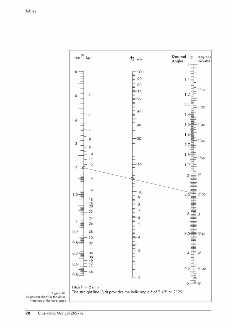
5.8. Calculating the helix angle
Normally, it is not necessary to know the helix angle of the thread to be cut, since the threads are listed in the chaser holder table in such a way that the corresponding holders can be read off directly.In special cases, however, not listed in the chaser holder table, the helix angle can be easily calculated with the aid of the alignment chart on page 28. It is essential to use the effective rather than the major diameter o‘ the thread concerned in the calculation. That is to say:
dm =
dm = effective diameterda = major diameterdk = minor diameter
The helix ankle is calculated in accordance with the expression:
tan =
P = pitch of thread in mm d = effective diameter.
The left-hand scale of the alignment chart on page 28 represents values of "P"‘, the centre scale represents values of "d", and the right-hand scale represents the pitch angle . The latter value is calibrated in decimal form on the left-hand side of the scale and in degrees and minutes of arc on the right-hand side of the scale.The pitch of the desired thread is found on the "P"-scale and the effective diameter is found on the "d"-scale. The straight line connecting these points will pass through the -scale and give the desired helix angle.
In the example shown the helix angle for an M16 metric thread is calculated. The effective diameter is equal to:
dm = = = 14.701
The flank diameter is also equal to 14.701. The pitch “P” is equal to 2 mm. The straight line "P-d" provides the helix angle of 2.49° or 2° 29‘ .In most cases the effective diameter is almost identical with the flank diameter; the later may therefore be used in these calculations.
P( · d)
da + dk2
da + dk2
16 + 13.4022
28 Operating Manual ZR27-2
Tables
Pitch P = 2 mmThe straight line (P-d) provides the helix angle of 2.49° or 2° 29‘ .Figure 10:
Alignment chart for the deter-mination of the helix angle

Operating Manual ZR27-2 29
Spare parts for thread cutting head ZR27-2
9. Spare parts for thread cutting head ZR27-2
List of spare parts thread cutting head ZR 27-2Product No. 73800000
ID Qty. Article No. Designation
1 1 738957 Head body
2 1 724550 Excentric ring
3 4 705165 Spring-loaded cylinder
4 4 03310047 Compression spring 0.9x6.6x17.0
5 4 02030055 Shoulder stud M4x8 DIN 427
6 1 02160002 Key DIN 6885
7 1 02020207 Countersunk screw M8x15 DIN 63-5.8
8 1 724552 Guide ring
9 1 705255 Sliding key
10 4 02016104 Cheese head screw M6x16
11 2 705166 Key plate
12 2 02015060 Socket screw M5x30 DIN 912-12.9
16 1 03310039 Compression spring 0.8x5.2x15.5
17 1 705164 Stop pin
18 1 02016002 Cheese head screw M4x10
35 1 03310044 Compression spring 0.9x6.1x14.0
36 1 02460123 Steel ball DIN 5401
37 1 73800900 Cover ZR27-2 10x12,7
38 1 02016054 Cheese head screw M5x16 DIN6912 8.8
39 1 02046155 Threaded pin M6x12 DIN 914- 12.9
Accessories Head
27 1 03697201 Allen key with screw driver
29 1 731040 Taper key
19 4 Chaser holder
21 8 03011702 Clamping screw
22 4 Clamping plate (according to type of holder)
23 4 Adjusting screw (according to type of holder)
24 4 701998 Sliding pad
25 4 Packing (according to type of holder)
30 1 02677006 Allen key 6 DIN 911
34 4 02020056 Countersunk screw M4x10 DIN 63

30 Operating Manual ZR27-2
Spare parts for thread cutting head ZR27-2
Carrier ring Product No. 705253
26 2 705249 Carrier jaw 117/80x14
32 1 705248 Carrier ring
33 2 705250 Carrier screw M10x1 RD14x36
Setting device Product No. 733970
E21 1 733971 Setting bracket
E21.1 1 02035508 T-headed screw
E21.2 1 03240186 pressure pad
E22 1 733972 Dial gauge holder
E23 1 705263 Stop
E24 1 02035416 Clamping screw
E25 1 705260 Setting gauge
E26 1 06525003 Dial gauge
Grinding Fixture
S1 Lower section
S2 Center section
S3 Upper section
S4 Knurled screw
Grinding fixture
Setting device

Operating Manual ZR27-2 31
Spare parts for thread cutting head ZR27-2

32 Operating Manual ZR27-2
Single Parts for the die head with special detent ZR 27-AR
10. Single Parts for the die head with special detent ZR 27-AR
No. Quantity Product no. Designation
37 1 73801600 Toothed segment (set = 20 pieces)
38 1 73560000 Cheese head
39 1 Thread pin

Operating Manual ZR27-2 33
Mounting of die heads ZR 27-2
11. Mounting of die heads ZR 27-2
The spring-loaded ball catch prevents the head from opening on account of vibra-tions (especially when cutting brass).When drilling the bore dp on the spindle, do not drill through the bore in the sliding key.
Type of head
Dimensions Kugel-Øc d dP e f g n p q r s t u
ZR 27-2 60 47 8 6.4 35 3.2 18 4 54 9 14 6.25+0.2 14 7.5
Screws for fixture: M6x25
stroke for holder change

ImprintThis operating manual is a publication made by WAGNER® Werkzeugsysteme Müller GmbH. Information in this catalog is current as of publication date and subject to change.All rights reserved.
06 | 2015
Werkzeugsysteme Müller GmbHGutenbergstraße 4/1D-72124 Pliezhausen
phone: +49(0) 71 27/ 97 33-00fax: +49(0) 71 27/ 97 33-90
email: [email protected]: www.wagner-werkzeug.de