operating manual vegetable cutter › documents › product... · 2020-06-17 · • the anliker l...
TRANSCRIPT

Operating Manual Vegetable Cutter
ANLIKER L Translation of the German Original

Generated: Reviewed: Revised: Status: 300 released Page 2 of 29 Ralph Moretti Michel Benkovics Ralph Moretti Document number: Index 12.02.2019 22.05.2019 235.01531 AB
Table of contents 1 ANLIKER L Introduction ............................................................................................................. 5 1.1 Operating manual ................................................................................................................ 5 1.1.1. Scope of application ............................................................................................................. 5 1.1.2. Target groups and mandatory reading ................................................................................... 5 1.1.3. Warnings and instructions for use ......................................................................................... 6 1.1.4. Abbreviations and symbols ................................................................................................... 6 1.2 Manufacturer address .......................................................................................................... 6 1.3 Device identification ............................................................................................................ 7 2 Safety ..................................................................................................................................... 7 2.1 Intended use ....................................................................................................................... 7 2.2 General safety guidelines ...................................................................................................... 8 2.3 User requirements ............................................................................................................... 8 3 Structure ................................................................................................................................. 9 3.1 Structure ............................................................................................................................ 9 3.2 Equipment ........................................................................................................................ 10 3.3 Accessories ....................................................................................................................... 10 3.4 Materials .......................................................................................................................... 11 3.5 Control elements for activation and deactivation .................................................................. 11 4 Structure of the ANLIKER L vegetable cutter ............................................................................. 11 4.1 Consignment ..................................................................................................................... 11 4.2 Reporting Damage ............................................................................................................. 11 4.3 Weight of the ANLIKER L vegetable cutter ............................................................................ 12 4.4 Unpacking ......................................................................................................................... 12 4.5 Transport of the ANLIKER L vegetable cutter ......................................................................... 13 4.6 Assembly and installation ................................................................................................... 13 4.7 Electrical / electronic configuration ...................................................................................... 14 4.8 Start-up ............................................................................................................................ 15 4.9 Storage ............................................................................................................................. 16 5 Operation .............................................................................................................................. 17 5.1 Correct insertion of the cutting disks, grating disks and dicers ........................................................ 17 5.1.1 Preparing the ANLIKER L vegetable cutter ........................................................................................ 17 5.1.2 Inserting the ejector or ejector disk .................................................................................................. 17 5.1.3 Inserting the cutting or grating disk .................................................................................................. 17 5.1.4 Closing the top .................................................................................................................. 18 5.2 Cutting vegetables ............................................................................................................. 18 5.3 Correct plunger handling: ................................................................................................... 19 5.4 Handling of accessories (Double Shot): ................................................................................. 20 5.4.1 Preparation for use of the Double Shot. ........................................................................................... 20 5.4.2 Operating the Double Shot ................................................................................................. 20

Generated: Reviewed: Revised: Status: 300 released Page 3 of 29 Ralph Moretti Michel Benkovics Ralph Moretti Document number: Index 12.02.2019 22.05.2019 235.01531 AB
6 System care „cleaning concept“ .............................................................................................. 21 6.1 Cleaning the ANLIKER L vegetable cutter .......................................................................................... 21 6.2 Removing the top .............................................................................................................................. 21 6.3 Cleaning the cutting disks and inserts............................................................................................... 22 6.3.1 Cleaning the dicer grid ...................................................................................................................... 22 6.3.2 Soft residues in the dicer grid ........................................................................................................... 22 6.3.3 Hard residues in the dicer grid .......................................................................................................... 22 6.3.4 Manual cleaning of the dicer grid ..................................................................................................... 22 6.3.1 Inserting the plunger rod .................................................................................................... 23 7 Troubleshooting..................................................................................................................... 24 7.1 Elimination of malfunctions .............................................................................................................. 24 7.1.1 Device does not run .......................................................................................................................... 24 7.1.2 Device clogged .................................................................................................................................. 24 7.1.3 Cutting element W cannot be removed ........................................................................................... 24 7.1.4 The cutting quality (surface structure) keeps deteriorating ............................................................. 25 7.1.5 The knife does not move freely ........................................................................................................ 25 7.1.6 Cutter bar broken .............................................................................................................................. 25 7.1.7 The device can no longer be switched off. ....................................................................................... 25 7.1.8 The device makes buzzing noises and runs irregularly ..................................................................... 25 7.1.9 The plunger plate is jammed ............................................................................................................ 25 7.2 Service and information ..................................................................................................... 25 8 Spare Parts ............................................................................................................................ 26 8.1 Disposal ............................................................................................................................ 26 9 Device transfer to third parties ................................................................................................ 27 10 Technical Specifications .......................................................................................................... 27 10.1 Warranty .......................................................................................................................... 27 10.2 Dimensional drawing of the ANLIKER L vegetable cutter ......................................................... 28 10.3 CE Conformity Declaration .................................................................................................. 29

Generated: Reviewed: Revised: Status: 300 released Page 4 of 29 Ralph Moretti Michel Benkovics Ralph Moretti Document number: Index 12.02.2019 22.05.2019 235.01531 AB
List of illustrations Fig. 1: Nameplate .............................................................................................................................................7 Fig. 2: System components - part 1 Fig. 3: System components - part 2 .......................................................................................................9 Fig. 4: ANLIKER L Fig. 5: Standard equipment........................................................................................................................... 10 Fig. 6: Ejector disk and ejector Fig. 7: Cutting disks Fig. 8: Dicer grid with dicer knife ............................................................................................................. 10 Fig. 9: Double Shot Fig. 10: Plunger ............................................................................................................................... 10 Fig. 11: Locking lever ..................................................................................................................................... 11 Fig. 12: Cardboard box Fig. 13: Packed in styrofoam elements ........................................................................................................ 11 Fig. 14: Taking the device out of the cardboard box .................................................................................... 12 Fig. 15: How to carry the device ................................................................................................................... 13 Fig. 16: Open the top .................................................................................................................................... 17 Fig. 17: Installed ejector disk Fig. 18: Installed ejector ................................................................................................................ 17 Fig. 19: Correctly placed disk ........................................................................................................................ 17 Fig. 20: Guiding the plunger with both hands Fig. 21: with one hand Fig. 22: from the center .................................................................................... 19 Fig. 23: Remove the plunger Fig. 24: Insert the Double Shot Fig. 25: Lock the device ................................................................................................................ 20 Fig. 26: Device locked Fig. 27: Plunger inserted ........................................................................................................................... 20 Fig. 28: Removing the plunger Fig. 29: Hold the top Fig. 30: Remove the top ............................................................................................................. 21 Fig. 31: Place the top Fig. 32: Insert the plunger Fig. 33: Snap the plunger in place ................................................................................................................. 23 Fig. 34: Device bottom .................................................................................................................................. 24 Fig. 35: Dimensional drawing of the ANLIKER L vegetable cutter ................................................................ 28 Fig. 36: CE Conformity Declaration ............................................................................................................... 29 List of tables Table 1: Nameplate ..........................................................................................................................................7 Table 2: System components ...........................................................................................................................9 Table 3: Device bottom ................................................................................................................................. 24 Table 4: Technical data of the ANLIKER L vegetable cutter .......................................................................... 27

Generated: Reviewed: Revised: Status: 300 released Page 5 of 29 Ralph Moretti Michel Benkovics Ralph Moretti Document number: Index 12.02.2019 22.05.2019 235.01531 AB
1 ANLIKER L Introduction This chapter informs on the scope of application and structure of the operating manual.
1.1 Operating manual This operating manual enables the correct use and safe application of the ANLIKER L vegetable cutter made by Brunner-Anliker AG. Important: The operating manual must be readily accessible for all users of the ANLIKER L vegetable cutter and therefore kept close to the machine.
1.1.1. Scope of application This operating manual applies exclusively to the ANLIKER L vegetable cutter made by Brunner-
Anliker AG. Date of issue of this operating manual: 12.2018 The manual provides instructions on the preparation, operation and maintenance of the fully
functional vegetable cutter and information on how to eliminate malfunctions. It is not meant, however, for the execution of repairs of cutter defects. If repairs become necessary, please contact your supplier or the manufacturer.
1.1.2. Target groups and mandatory reading The operating manual addresses all users of the ANLIKER L vegetable cutter. Mandatory reading All users are to read section 2 “Safety”, page 7, before they start working with the ANLIKER L vegetable cutter.

Generated: Reviewed: Revised: Status: 300 released Page 6 of 29 Ralph Moretti Michel Benkovics Ralph Moretti Document number: Index 12.02.2019 22.05.2019 235.01531 AB
1.1.3. Warnings and instructions for use Please observe the following warning symbols and instructions for use.
HAZARD HAZARD
Indicates that death or serious physical injury will occur if the respective precautions are not taken.
WARNING WARNING
Indicates that death or serious physical injury may occur if the respective precautions are not taken.
CAUTION
CAUTION Indicates that minor bodily injury or damage to property may occur if the respective precautions are not taken.
NOTE
Note User information for technically correct and efficient use of the product or for better understanding of the product characteristics.
1.1.4. Abbreviations and symbols We use abbreviations and easy to recognize symbols at the page margins only for measuring units and the above mentioned warning and usage symbols. (Examples: see “Warnings and instructions for use”, page 6). In this manual, the ANLIKER L vegetable cutter will also be referred to as the “device”.
1.2 Manufacturer address Brunner-Anliker AG Brunnergässli 1 - 5 8302 Kloten Switzerland Phone: +41 44 804 21 00 Mail: [email protected]

Generated: Reviewed: Revised: Status: 300 released Page 7 of 29 Ralph Moretti Michel Benkovics Ralph Moretti Document number: Index 12.02.2019 22.05.2019 235.01531 AB
1.3 Device identification
Please indicate the device ID stamped on the nameplate attached to the back of the ANLIKER L vegetable cutter for all inquiries and spare part orders. This will help us to answer your questions fast and correctly. Information of the nameplate necessary for device identification: (for example:)
Fig. 1: Nameplate
Item Item 1 Producer / contact data 5 Item number 2 Serial number 6 Date of manufacture 3 Device name 7 Motor performance characteristics 4 Certification
Table 1: Nameplate
2 Safety This chapter provides information on the general safety guidelines that need to observed when handling and working with the ANLIKER L vegetable cutter.
2.1 Intended use The intended use of the ANLIKER L vegetable cutter is the cutting and slicing of different types of
vegetables in the catering and food processing industry. With the various cutting disks, the vegetables can be cut into different shapes and sizes. Only original cutting disks and the spare parts recommended by the manufacturer may be used.
The intended use includes the compliance with the manufacturer instructions and conditions for installation, startup, maintenance and operation of the vegetable cutter.
Any use that does not comply with the intended one and in particular the use of third-party or defective cutting disks is, without prior written consent given by the manufacturer, considered as contrary to its intended use. The manufacturer cannot be held liable for damages resulting from improper use of the ANLIKER L vegetable cutter.

Generated: Reviewed: Revised: Status: 300 released Page 8 of 29 Ralph Moretti Michel Benkovics Ralph Moretti Document number: Index 12.02.2019 22.05.2019 235.01531 AB
2.2 General safety guidelines The following safety guidelines apply to the handling of the ANLIKER L vegetable cutter: • Every user is responsible for his own safety and health. The user is to not allowed to carry out
jobs whose risk he cannot assess. Such jobs need to be executed by persons qualified accordingly.
• All those working with the ANLIKER L vegetable cutter must have been instructed on its use, read and understood the manufacturer’s operating manual. See also “User requirements”, page 8.
• The instructions provided in this operating manual must be adhered to.
• The user is obligated to operate the ANLIKER L vegetable cutter in its fully functional state only and eliminate changes or defects, especially when related to safety issues, immediately.
• It is expressly prohibited to remove or alter safety devices and protective covers.
2.3 User requirements All those handling the device must have been instructed on its use beforehand. Any specific special training is, however, not necessary.
CAUTION
CAUTION Risk of injury if handled inexpertly! All those working with the ANLIKER L vegetable cutter need to have read and understood the operating manual or be instructed by experienced users prior to its utilization.
Generated: Reviewed: Revised: Status: 300 released Page 9 of 29 Ralph Moretti Michel Benkovics Ralph Moretti Document number: Index 12.02.2019 22.05.2019 235.01531 AB
3 Structure This chapter informs on the structure and accessories of the device.
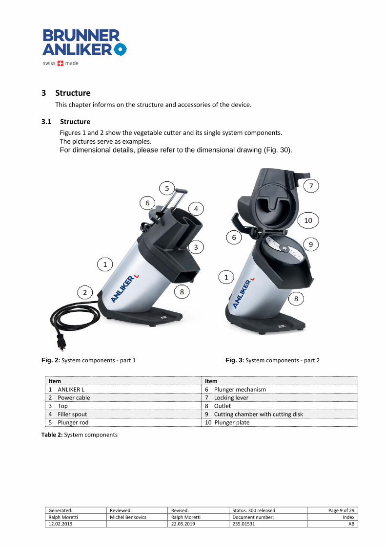
3.1 Structure Figures 1 and 2 show the vegetable cutter and its single system components. The pictures serve as examples. For dimensional details, please refer to the dimensional drawing (Fig. 30).
Fig. 2: System components - part 1 Fig. 3: System components - part 2
Item Item 1 ANLIKER L 6 Plunger mechanism 2 Power cable 7 Locking lever 3 Top 8 Outlet 4 Filler spout 9 Cutting chamber with cutting disk 5 Plunger rod 10 Plunger plate
Table 2: System components

Generated: Reviewed: Revised: Status: 300 released Page 10 of 29 Ralph Moretti Michel Benkovics Ralph Moretti Document number: Index 12.02.2019 22.05.2019 235.01531 AB
3.2 Equipment The device is available with different cutting and grating disks as well as with cutting disks equipped with knives for dicing. All cutters come with operating manual, cleaning brush and fuse kit.
Fig. 4: ANLIKER L Fig. 5: Standard equipment
3.3 Accessories The vegetable cutter can be equipped with a Double Shot with plunger for long vegetables such as cucumbers, carrots and similar. Supplementary accessories plus a large variety of cutting and grating disks as well as disk holders can be ordered from our Sales department or at our webshop.
Fig. 6: Ejector disk and ejector Fig. 7: Cutting disks Fig. 8: Dicer grid with dicer knife
Fig. 9: Double Shot Fig. 10: Plunger

Generated: Reviewed: Revised: Status: 300 released Page 11 of 29 Ralph Moretti Michel Benkovics Ralph Moretti Document number: Index 12.02.2019 22.05.2019 235.01531 AB
3.4 Materials All housing components plus top are made of fiberglass compounds.
3.5 Control elements for activation and deactivation ANLIKER L vegetable cutter operating concept:
1. Connect the device to the mains supply and make sure that the top is mounted and secured with the plunger rod.
2. As soon as the locking lever is locked and the plunger plate sits in the filler spout, the device switches on.
3. The device switches automatically off when the locking lever on the top is unlocked and the plunger plate no longer sits in the filler spout.
Fig. 11: Locking lever
4 Structure of the ANLIKER L vegetable cutter
4.1 Consignment The device is consigned packed in a cardboard box and protected by styrofoam elements (see Fig. 12 and 13).
Fig. 12: Cardboard box Fig. 13: Packed in styrofoam elements
The ANLIKER L vegetable cutter was cleaned at the manufacturer before dispatch. We recommend, however, to clean the device prior to its first use with a food grade cleaning product.
4.2 Reporting Damage Notify the forwarder, insurance agent, supplier / service center immediately If the vegetable cutter is consigned damaged due to insufficient packaging or inadequate transport. The contact addresses are listed on pages 6 and 24.

Generated: Reviewed: Revised: Status: 300 released Page 12 of 29 Ralph Moretti Michel Benkovics Ralph Moretti Document number: Index 12.02.2019 22.05.2019 235.01531 AB
4.3 Weight of the ANLIKER L vegetable cutter The vegetable cutter weighs 19 kg.
4.4 Unpacking Prior to any utilization or transport of the vegetable cutter, remove the protective styrofoam and other pluggable elements (e.g. cable clips) used for transport. Best place the cardboard box in vertical position and pull out the device (see Fig. 14).
Fig. 14: Taking the device out of the cardboard box
NOTE
Note • Check the consignment for completeness. Compare the contents with the
delivery note. If components are missing, please contact your supplier. • Notify our after-sales service, the forwarder and the insurance agent
immediately if the device is consigned damaged due to insufficient packaging or inadequate transport.
CAUTION
CAUTION! • Heavy load! The heavy weight might damage the musculoskeletal system. • Always use an appropriate load-carrying device for transport.

Generated: Reviewed: Revised: Status: 300 released Page 13 of 29 Ralph Moretti Michel Benkovics Ralph Moretti Document number: Index 12.02.2019 22.05.2019 235.01531 AB
4.5 Transport of the ANLIKER L vegetable cutter Always use an appropriate load-carrying device for transport.
Or carry the device as illustrated in figure 15.
Fig. 15: How to carry the device
4.6 Assembly and installation Ensure ergonomic work situations: Always place the device on a adequately high, plane and solid worktop with a minimum size of 300 mm x 400 mm. Leave sufficient space in front of the device to allow the placement of a suitable container under the outlet opening. Food container H = 150 mm, sizes 2/3 or 1/1 fit perfectly beneath the outlet.
Leave sufficient space behind the device to allow the top to swing open and to exchange the cutting disks and cutting inserts.
Connect the machine as close as possible to the power outlet. Avoid tripping hazards! Do not route the cables where people walk frequently!
If you are uncertain about the installation site and/or have questions regarding the installation, please contact Brunner-Anliker AG (the contact address is provided on page 6 or 25).

Generated: Reviewed: Revised: Status: 300 released Page 14 of 29 Ralph Moretti Michel Benkovics Ralph Moretti Document number: Index 12.02.2019 22.05.2019 235.01531 AB
4.7 Electrical / electronic configuration Depending on the cutter version, the device is designed for a 115V 60Hz / 230V 50Hz/60Hz network. The device can be plugged into a standard socket which must, however, be appropriately fused. The electrical installation of the ANLIKER L vegetable cutter is subject to the following guidelines:
HAZARD
HAZARD! • Defective electrical components may be live and pose a life-threatening hazard. • Do not drive over, crush or pull on the cable(s). • Disconnect the device from the mains supply before working on the electrical
equipment. • Eliminate defects on electric components / modules immediately. In the event of
and to avoid acute danger, the equipment must not be operated in defective or inadequate condition.
CAUTION
CAUTION! • Please observe the electrical data on the nameplate (see also page 7) before
connecting the device to the mains supply.
NOTE
Note • Brunner-Anliker AG does not accept any liability for events and damages
originating from electrical installation • Protection against unexpected start-up: observe the national regulations!

Generated: Reviewed: Revised: Status: 300 released Page 15 of 29 Ralph Moretti Michel Benkovics Ralph Moretti Document number: Index 12.02.2019 22.05.2019 235.01531 AB
4.8 Start-up Please observe the following guidelines for first startup and test run. • Ensure that there are no foreign bodies in the vegetable cutter’s filler spouts!
HAZARD
HAZARD! • Do not change or modify the ANLIKER L vegetable cutter or add any equipment
which might impair the safety or function of the device Otherwise the device no longer complies with the CE standards.
• Check the ANLIKER L safety functions at regular intervals. Malfunctions may massively impair its functions and result in severe injury to personnel and/or damage to the machine!
CAUTION
CAUTION! • Always adhere to the local accident prevention regulations!
NOTE
Note
• The user must have read and understood the operating manual and in particular the chapter on safety regulations before working with the machine.

Generated: Reviewed: Revised: Status: 300 released Page 16 of 29 Ralph Moretti Michel Benkovics Ralph Moretti Document number: Index 12.02.2019 22.05.2019 235.01531 AB
4.9 Storage If the ANLIKER L vegetable cutter is not used for a longer period of time, observe the following conditions to keep it fully functional: • The storage place must be dry and clean. • The ANLIKER L vegetable cutter must not be exposed to extreme cold or heat. • The device must be kept clean. • The ANLIKER L vegetable cutter must be packed or covered against the ingress of dirt and dust.
NOTE
Note
• Brunner-Anliker AG cannot be held liable for damages caused by corrosion due to improper storage, e.g. in moist rooms or similar.
Please contact our after-sales service before returning the machine into service after a prolonged period of standstill.
All mechanical parts need to be inspected. In particular: • check all components for corrosion (and deterioration) damage. • check all cutting disks for damage and cutting quality.

Generated: Reviewed: Revised: Status: 300 released Page 17 of 29 Ralph Moretti Michel Benkovics Ralph Moretti Document number: Index 12.02.2019 22.05.2019 235.01531 AB
5 Operation The ANLIKER L vegetable cutter can be used for a myriad of jobs. Observe the following steps when inserting cutting disks, grating disks and dicers:
5.1 Correct insertion of the cutting disks, grating disks and dicers
5.1.1 Preparing the ANLIKER L vegetable cutter
First open the locking lever and swing up the top.
Fig. 16: Open the top
5.1.2 Inserting the ejector or ejector disk
Prior to inserting the cutting disk, install the ejector or ejector disk. It sits correctly when it almost (but not quite) touches the bottom of the cutting chamber. Without ejector/ejector disk, the cut food accumulates beneath the cutting disk, the disk is pushed up and so might damage cutting head and knives.
Fig. 17: Installed ejector disk Fig. 18: Installed ejector
5.1.3 Inserting the cutting or grating disk
Place the disk on the drive shaft. Turn the disk slightly until it engages with the pin on the drive shaft and sits correctly (observe upper flushness with the drive shaft). Correct cutting disk placement is possible only if hub and pin are absolutely clean.
Fig. 19: Correctly placed disk

Generated: Reviewed: Revised: Status: 300 released Page 18 of 29 Ralph Moretti Michel Benkovics Ralph Moretti Document number: Index 12.02.2019 22.05.2019 235.01531 AB
WARNING
WARNING • The knives and tips of the grating disk perforations are extremely sharp and now
lie open.
• Danger of cuts and skin abrasions! NOTE
Note
• The disks fit the drive shaft perfectly. Never push of force them down on the drive shaft with an excess of pressure.
5.1.4 Closing the top
Fold the top back in place and proceed as explained in “Cutting vegetables”, page 18.
5.2 Cutting vegetables Put a suitable container under the outlet opening of the device. Food containers H = 150 mm, sizes 2/3 or 1/1 fit perfectly beneath the outlet. 1. Pull up the plunger plate located in the kidney-shaped filler spout and fold it up and
backwards. 2. Fill the filler spout with vegetables.
Close the plunger plate all the way (i.e. the plate must rest on the vegetables above the kidney-shaped filler neck).
3. Close the locking lever (push down). The device can now be started. Push the plunger with slight pressure onto the vegetables for optimum cutting.
4. Repeat steps 1 to 3 when the filler neck is empty. At the end of the cutting process, release the locking lever. The device stops and switches off.

Generated: Reviewed: Revised: Status: 300 released Page 19 of 29 Ralph Moretti Michel Benkovics Ralph Moretti Document number: Index 12.02.2019 22.05.2019 235.01531 AB
5.3 Correct plunger handling: Exert slight pressure on the plunger with both hands or with one hand placed near the plunger rod or with one hand placed at the center
Fig. 20: Guiding the plunger with both hands Fig. 21.. with one hand Fig. 22: …from the center
NOTE
Note • Correct guiding of the plunger. • To prevent the plunger from getting stuck, push it down with both hands or
with one hand at the center.
If you want to cut the vegetables to a certain shape, e.g. onions or tomatoes, they must be put into the filler neck in the respective direction. Tip: If long vegetables are arranged vertically in the device, they are cut cross-wise into small pieces. If long vegetables are arranged horizontally in the device, they are cut into long pieces.
NOTE
Note • The vegetables must be led and not pressed down by the plunger plate. Strong
pressure is not necessary and reduces the cut quality. • Neither does strong pressure increase the output amount / performance.

Generated: Reviewed: Revised: Status: 300 released Page 20 of 29 Ralph Moretti Michel Benkovics Ralph Moretti Document number: Index 12.02.2019 22.05.2019 235.01531 AB
5.4 Handling of accessories (Double Shot): The insert allows the continuous infeed and cutting of long products such as cucumbers.
5.4.1 Preparation for use of the Double Shot First completely remove the plunger (Fig. 23). Then insert the Double Shot. Observe the following steps: Pull back the safety pin (Fig. 24), place the Double Shot in the filler spout, lock the device with the safety pin (Fig. 25).
Fig. 23: Remove the plunger Fig. 24: Insert the Double Shot Fig. 25: Lock the device
5.4.2 Operating the Double Shot
After execution of the above steps, the Double Shot can be put into operation. Important: the safety pin must be in locked position as shown in Fig. 26. Start the machine with the locking lever and feed in the vegetables. Use the plunger to push down the vegetables (Fig. 27). Open the locking lever to stop the machine.
Fig. 26: Device locked Fig. 27: Plunger inserted

Generated: Reviewed: Revised: Status: 300 released Page 21 of 29 Ralph Moretti Michel Benkovics Ralph Moretti Document number: Index 12.02.2019 22.05.2019 235.01531 AB
6 System care „cleaning concept“
6.1 Cleaning the ANLIKER L vegetable cutter The ANLIKER L vegetable cutter is made of low-maintenance fiberglass compound and therefore easy to clean. The top can be completely taken off for easy cleaning. Top, plunger and ejector can be cleaned and disinfected in the dishwasher. The cutting chamber of the device can be cleaned with a damp cloth or the brush included in the consignment. The device (basic unit) itself, however, must not be put and cleaned in the dishwasher!
6.2 Removing the top Hold the top so it cannot move (Fig. 24), fold back the plunger and push out of the opening (Fig. 23). The top can now be removed (Fig. 25).
Fig. 28: Removing the plunger Fig. 29: Hold the top Fig. 30: Remove the top
NOTE
Note
• The ANLIKER L vegetable cutter must not be cleaned in the dishwasher.
Generated: Reviewed: Revised: Status: 300 released Page 22 of 29 Ralph Moretti Michel Benkovics Ralph Moretti Document number: Index 12.02.2019 22.05.2019 235.01531 AB
6.3 Cleaning the cutting disks and inserts Use the nylon brush included in the consignment to clean the cutting and grating disks, the dicing knives and inserts under running water. Never clean the dicer grid with metal objects or by tapping it on the edge of a table. Best clean the grid in a combi steam oven at 90 degrees for about 10 minutes. Then brush the vegetable residues off under running water (the brush is part of the consignment).
NOTE
Note
• Cleaning in the dishwasher might reduce the life of the knives.
6.3.1 Cleaning the dicer grid
After vegetable processing, the square disk holes are filled with vegetable residues. Proceed as follows to remove the vegetable/fruit residues:
6.3.2 Soft residues in the dicer grid
Soft vegetable and fruit types such as tomatoes, peppers, pears, kiwis, bananas, avocados etc are easily removed by holding the back of the grid under running water and brushing it with the brush included in the consignment.
6.3.3 Hard residues in the dicer grid
Hard vegetable and fruit types can be removed in two different yet gentle ways: If you own a combi steam oven: Put the dicer grid into 90-degree oven for about 10 minutes to cook the residues. Then hold the front of the grid under running water and brush the rests out with the brush included in the consignment.
6.3.4 Manual cleaning of the dicer grid
Insert the dicer grid without knife into the device. Hold the dicer grid with one hand (fingers on the outer rim). Remove the vegetables with the other hand by pushing a raw, long carrot horizontally onto and through the grid holes. Then hold the front of the grid under running water and brush the remaining vegetable pieces off with the brush included in the consignment. Pieces stuck in the holes near the grid edges can be removed with a thin wooden skewer.
NOTE

Generated: Reviewed: Revised: Status: 300 released Page 23 of 29 Ralph Moretti Michel Benkovics Ralph Moretti Document number: Index 12.02.2019 22.05.2019 235.01531 AB
Note
• Use food grade detergents only. (no industrial fat solvents)
WARNING
WARNING • Ensure that the device is switched off with the ON/OFF switch prior to any
maintenance job. • Disconnect from the mains! • The ANLIKER L vegetable cutter must not be cleaned with a stream-jet or high-
pressure washers. • The use of abrasive cleaning agents is strictly prohibited.
CAUTION
CAUTION • The knives are extremely sharp and now lie open. • Danger of cuts and skin abrasions!
6.3.1 Inserting the plunger rod
Ensure that the tappets snap into the opening (do not exert pressure).
Fig. 31: Place the top Fig. 32: Insert the plunger Fig. 33: Snap the plunger in place

Generated: Reviewed: Revised: Status: 300 released Page 24 of 29 Ralph Moretti Michel Benkovics Ralph Moretti Document number: Index 12.02.2019 22.05.2019 235.01531 AB
7 Troubleshooting The following chapter describes possible malfunctions which might occur during operation, and their elimination.
7.1 Elimination of malfunctions The machine is built to endure and therefore not very susceptible to malfunctions. Action in case of malfunctions: First measure in case of malfunctions: Switch off the device! In case of unpleasant smells, unplug the mains plug.
7.1.1 Device does not run
1. Check the socket function by connecting another device. 2. Check the micro-fuse. The fuse protects the switching amplifier against excess voltage and
power fluctuations. It is located on the bottom of the device next to the cable outlet. 3. If the device still does not work, contact a technician or the Brunner-Anliker after-sales service.
Fig. 34: Device bottom
Item Item 1 Power cable 2 Micro-fuse
Table 3: Device bottom
7.1.2 Device clogged
Nothing goes in, nothing comes out. Switch off the device, take apart and clean (see item 7).
7.1.3 Cutting element W cannot be removed
The bayonet catch was not unlocked correctly. Rotate the dicing knife carefully counterclockwise and keep in place to allow unlocking of the bayonet catch and simultaneous removal of both parts from below.

Generated: Reviewed: Revised: Status: 300 released Page 25 of 29 Ralph Moretti Michel Benkovics Ralph Moretti Document number: Index 12.02.2019 22.05.2019 235.01531 AB
7.1.4 The cutting quality (surface structure) keeps deteriorating
If the quality of the cut diminishes, the respective cutting disk should be replaced. We provide attractive exchange options! Get in touch with us.
Please note: If you have to exert strong pressure on the plunger, the cutting disks are most likely blunt and should be replaced. Call the Brunner-Anliker AG service department or order from our webshop at www.brunner-anliker.com.
7.1.5 The knife does not move freely
A) the hub is dirty and the knife does not sit correctly B) the ejector has not been inserted.
7.1.6 Cutter bar broken
The cutter bars can break when they are no longer sharp or if they are collide with an object. IMPORTANT: Always search for the knife or its parts when broken.
WARNING
WARNING • High risk of injury for the customer/guest. • The responsibility for these malfunctions lies with the user.
7.1.7 The device can no longer be switched off.
The magnetic switch is defective. Please contact a technician.
7.1.8 The device makes buzzing noises and runs irregularly
The capacitor is defective. Please contact a technician.
7.1.9 The plunger plate is jammed
Clean the plunger rod with soap.
7.2 Service and information Please contact our Service Line for all problems and questions that are not described or cannot be solved. Address: Brunner-Anliker AG Brunnergässli 1 - 5 T: +41 44 804 21 00 8302 Kloten F: +41 44 804 21 90 Switzerland [email protected] More information on our website at brunner-anliker.com

Generated: Reviewed: Revised: Status: 300 released Page 26 of 29 Ralph Moretti Michel Benkovics Ralph Moretti Document number: Index 12.02.2019 22.05.2019 235.01531 AB
8 Spare Parts Spare parts must meet the technical requirements specified by the manufacturer. This compliance is guaranteed for original spare parts. Use original spare parts only. Our warranty is void if third-party parts or parts which have not been approved in writing are used.
NOTE
Note • Some wear and spare parts are subject to delivery periods and may not
always be available at short notice. • Please note that the delayed availability of spare parts may result in
consequential damage and production losses. • Always indicate the device number, device type and item number when
ordering spare parts.
8.1 Disposal Dispose of the system, system parts, accessories and packaging in an environmentally compatible manner.
NOTE
Note • Resource recycling instead of waste disposal! • Prior to their disposal, clean the materials of substances that might
endanger health and environment. • Bring metal parts to a metal collection point. • Bring plastic parts to a plastic collection point. • Bring electric parts to a collection point for electric components.
• See to professional disposal or contract a waste disposal company.
If this operating manual does not answer all of your questions, please feel free to contact our after-sales service (see page 25).

Generated: Reviewed: Revised: Status: 300 released Page 27 of 29 Ralph Moretti Michel Benkovics Ralph Moretti Document number: Index 12.02.2019 22.05.2019 235.01531 AB
9 Device transfer to third parties All liabilities by Brunner-Anliker AG cease if the ANLIKER L vegetable cutter is sold and transferred to a third party.
10 Technical Specifications
Machine type ANLIKER L vegetable cutter
Electrical connection 100 V – 240 V, 50/60Hz
Electric motor 0.26 kW
Weight 22.8 kg
Protection category IP 26, splashwater
Dimensions L x W x H 250 x 315 x 540
Table 4: Technical data of the ANLIKER L vegetable cutter
10.1 Warranty
During the warranty period, the machine may only be repaired and maintained by the manufacturer. Upon request, the manufacturer may authorize certain exceptions in writing. The warranty exclusively relates to the part to be replaced and its replacement at the manufacturer’s factory, but not to a service in connection with a warranty repair not conducted by the specialist staff at our service center (refer to page 25) or by the manufacturer plant itself. The guarantee for the ANLIKER L vegetable cutter covers 2 years; wear parts and incorrect handling are excluded from the guarantee.

Generated: Reviewed: Revised: Status: 300 released Page 28 of 29 Ralph Moretti Michel Benkovics Ralph Moretti Document number: Index 12.02.2019 22.05.2019 235.01531 AB
10.2 Dimensional drawing of the ANLIKER L vegetable cutter
Fig. 35: Dimensional drawing of the ANLIKER L vegetable cutter

Generated: Reviewed: Revised: Status: 300 released Page 29 of 29 Ralph Moretti Michel Benkovics Ralph Moretti Document number: Index 12.02.2019 22.05.2019 235.01531 AB
10.3 CE Conformity Declaration
Fig. 36: CE Conformity Declaration