operating manual - schneider electric · (translation of the original german operating manual) ......
TRANSCRIPT
Lexium ILM6208.2014
Operating Manual(Translation of the original German Operating Manual)
EIO
0000
0013
51.0
2
The information provided in this documentation contains general descriptions and/ortechnical characteristics of the performance of the products contained herein. Thisdocumentation is not intended as a substitute for and is not to be used for determiningsuitability or reliability of these products for specific user applications. It is the duty ofany such user or integrator to perform the appropriate and complete risk analysis,evaluation and testing of the products with respect to the relevant specific applicationor use thereof. Neither Schneider Electric nor any of its affiliated or subsidiary com‐panies are responsible or liable for a misuse of the information contained herein. If youhave any suggestions for improvements or amendments or have found errors in thispublication, please notify us.No part of this document may be reproduced in any form or by any means, electronicor mechanical, including photocopying, without express written permission of Schneid‐er Electric.All pertinent state, regional, and local safety regulations must be observed when in‐stalling and using this product. For reasons of safety and to help ensure compliancewith documented system data, only the manufacturer should perform repairs to com‐ponents.When devices are used for applications with technical safety requirements, the rele‐vant instructions must be followed.Failure to use Schneider Electric software or approved software with our hardwareproducts may result in injury, harm, or improper operating results.Failure to observe this information can result in injury or equipment damage.© 2014 Schneider Electric. All rights reserved.
Imprint
2 Lexium ILM62 Schneider Electric 08/2014EIO0000001351 08/2014

Contents
1 About this manual 71.1 Introduction ............................................................................................................... 71.2 Symbols, designator and display format of safety messages .................................. 7
2 Safety information 92.1 Proper use ................................................................................................................ 92.2 Qualification of Personnel ...................................................................................... 102.3 Residual risks ......................................................................................................... 102.3.1 Electrical parts ........................................................................................................ 112.3.2 Assembly and handling .......................................................................................... 122.3.3 Hot surfaces ........................................................................................................... 122.3.4 Magnetic and electromagnetic fields ...................................................................... 132.3.5 Hazardous movements .......................................................................................... 132.3.6 PELV circuits .......................................................................................................... 14
3 System overview 153.1 Logic Motion Controller .......................................................................................... 153.2 ILM62 system ......................................................................................................... 163.2.1 ILM62DB Distribution Box ...................................................................................... 163.2.2 ILM62 Servo Module .............................................................................................. 173.2.3 ILM62DC•000 Daisy Chain Connector Box ............................................................ 183.3 Type code ............................................................................................................... 193.3.1 ILM62CM Connection Module ................................................................................ 193.3.2 ILM62DB Distribution Box ...................................................................................... 193.3.3 ILM62 Servo Module .............................................................................................. 203.3.4 ILM62 Daisy Chain Connector Box ........................................................................ 213.3.5 ILM62 accessories ................................................................................................. 223.4 Nameplate descriptions .......................................................................................... 23
4 Indicators and control elements 264.1 Displays at the Connection Module ILM62CM ....................................................... 264.1.1 24Vdc LED ............................................................................................................. 274.1.2 DC bus LED ........................................................................................................... 274.2 Displays at the Distribution Box ILM62DB .............................................................. 274.2.1 DC bus LED ........................................................................................................... 284.2.2 Hybrid connection LED ........................................................................................... 284.3 Displays at the ILM62 Servo Module ...................................................................... 294.3.1 State LED ............................................................................................................... 304.3.2 Port LED ................................................................................................................. 30
Contents
Schneider Electric 08/2014 Lexium ILM62 3EIO0000001351 08/2014

4.3.3 S3 LED ................................................................................................................... 31
5 Planning 325.1 Electromagnetic Compatibility, EMC ...................................................................... 325.2 Control cabinet planning ......................................................................................... 355.2.1 Degree of protection ............................................................................................... 355.2.2 Mechanical and climatic environmental conditions in the control cabinet .............. 355.2.3 Using Cooling Units ................................................................................................ 365.3 Wiring notes ........................................................................................................... 375.3.1 Cable characteristics .............................................................................................. 385.3.2 ESD protection measures ...................................................................................... 395.3.3 Conditions for UL compliant use ............................................................................ 395.3.4 Fusing the mains connection .................................................................................. 395.3.5 Mains contactor ...................................................................................................... 395.3.6 Mains filter .............................................................................................................. 395.3.7 Mains chokes ......................................................................................................... 405.3.8 Leakage current ..................................................................................................... 405.3.9 Residual current operated protective device .......................................................... 415.4 Functional safety .................................................................................................... 425.4.1 Process minimizing risks associated with the machine .......................................... 425.4.2 Inverter Enable function ......................................................................................... 435.4.3 Setup, installation, and mounting ........................................................................... 485.4.4 Application proposals ............................................................................................. 515.4.5 Commissioning ....................................................................................................... 545.4.6 Best Practices and Prevention of Misuse ............................................................... 545.4.7 Maintenance ........................................................................................................... 555.4.8 Physical environment ............................................................................................. 555.4.9 Safety standards .................................................................................................... 565.5 Special Conditions .................................................................................................. 575.5.1 Low air pressure ..................................................................................................... 57
6 Installation and maintenance 596.1 Commissioning ....................................................................................................... 596.1.1 Preparing commissioning ....................................................................................... 606.1.2 Grinding the holding brake ..................................................................................... 616.1.3 Preparing the control cabinet ................................................................................. 616.1.4 Mechanical mounting ............................................................................................. 646.1.5 Wiring Power Supply Module LXM62P and Connection Module ILM62CM ........... 666.1.6 Wiring as of Connection Module ILM62CM in line structure or tree structure ........ 686.1.7 Wiring as of Connection Module ILM62CM in daisy chain structure ...................... 726.2 Maintenance, repair, cleaning ................................................................................ 756.2.1 Fuse replacement Connection Module ILM62CM .................................................. 766.2.2 Repair ..................................................................................................................... 786.2.3 Cleaning ................................................................................................................. 786.3 Spare part inventory ............................................................................................... 796.4 Device-, parts- or cable exchange .......................................................................... 806.4.1 Replacement of devices and cables of Connection Module ILM62CM .................. 826.4.2 Replacement of devices and cables of Distribution Box ILM62DB ........................ 846.4.3 Replacement of devices and cables of ILM62 Servo Module ................................ 86
Contents
4 Lexium ILM62 Schneider Electric 08/2014EIO0000001351 08/2014

7 Technical data 887.1 Definition of technical data ..................................................................................... 887.2 Ambient conditions ................................................................................................. 897.3 Standards and regulations ..................................................................................... 937.4 Motor options .......................................................................................................... 947.5 Mechanical and electrical data ............................................................................... 947.5.1 Connection Module ILM62CM ................................................................................ 947.5.2 Distribution Box ILM62DB ...................................................................................... 957.5.3 Daisy Chain Connector Box ................................................................................... 967.5.4 ILM motor controller .............................................................................................. 977.5.5 ILM070 Servo Motor ............................................................................................... 987.5.6 ILM100 Servo Motor ............................................................................................... 997.5.7 ILM140 Servo Motor ............................................................................................. 1007.5.8 Encoder ................................................................................................................ 1017.5.9 Motor shaft and bearings ...................................................................................... 1027.5.10 Holding brake (optional) ....................................................................................... 1037.6 Mounting arrangement and degree of protection ................................................. 1057.7 Torque/speed characteristic curves ..................................................................... 1057.8 Electrical connections ........................................................................................... 1117.8.1 Connection Module ILM62CM .............................................................................. 1117.8.2 Distribution Box ILM62DB .................................................................................... 1157.8.3 ILM62 Servo Module ............................................................................................ 1177.8.4 ILM62DC•000 Daisy Chain Connector Box .......................................................... 1187.9 Dimensions ........................................................................................................... 1207.9.1 Connection Module ILM62CM .............................................................................. 1207.9.2 Distribution Box ILM62DB .................................................................................... 1217.9.3 ILM62DC•000 Daisy Chain Connector Box .......................................................... 1227.9.4 ILM62 Servo Module ............................................................................................ 125
8 Optional module ILM62-DIO8 1308.1 Technical data ...................................................................................................... 1318.2 Installation ............................................................................................................ 1328.3 Electrical connections ........................................................................................... 1348.4 Dimensions ........................................................................................................... 1368.5 Wiring ................................................................................................................... 137
9 Appendix 1389.1 Contact addresses ............................................................................................... 1389.2 Product training courses ....................................................................................... 1389.3 Disposal ................................................................................................................ 1389.4 EC declaration of conformity ................................................................................ 139
Contents
Schneider Electric 08/2014 Lexium ILM62 5EIO0000001351 08/2014

9.5 Units and conversion tables ................................................................................. 1409.5.1 Length .................................................................................................................. 1409.5.2 Mass ..................................................................................................................... 1409.5.3 Force .................................................................................................................... 1409.5.4 Power ................................................................................................................... 1409.5.5 Rotation ................................................................................................................ 1409.5.6 Torque .................................................................................................................. 1419.5.7 Moment of inertia .................................................................................................. 1419.5.8 Temperature ......................................................................................................... 1419.5.9 Conductor cross-section ....................................................................................... 141
Contents
6 Lexium ILM62 Schneider Electric 08/2014EIO0000001351 08/2014

1 About this manual
1.1 Introduction
Read and understand the material contained in this manual before you work on theILM62 component for the first time. Take particular note of the safety information (see2.3 Residual risks). As described in section 2.2, only those persons who meetthe "Selection and qualification of employees" are allowed to work on the ILM62 com‐ponents.A copy of this manual must be available for personnel who work on the ILM62 com‐ponents.This manual is supposed to help you use the capabilities of the ILM62 componentsafely and properly.Follow the instructions within this manual to:
• avoid risks• reduce repair costs and downtime of the ILM62 components• increase the service life of the ILM62 components,• increase reliability of the ILM62 components.
1.2 Symbols, designator and display format of safety messages
Important InformationNOTE Read these instructions carefully, and look at the equipment to become familiar with
the device before trying to install, operate, or maintain it. The following special mes‐sages may appear throughout this documentation or on the equipment to warn of po‐tential hazards or to call attention to information that clarifies or simplifies a procedure.
The addition of this symbol to a Danger or Warning safety label indicates that an electricalhazard exists, which will result in personal injury if the instructions are not followed.
This is the safety alert symbol. It is used to warn the user of potential personal injuryhazards. Obey all safety messages that follow this symbol to avoid possible injury ordeath.
DANGERDANGER indicates an imminently hazardous situation which, if not avoided, will result in deathor serious injury.
WARNINGWARNING indicates a potentially hazardous situation which, if not avoided, can result in deathor serious injury.
1.1 Introduction
Schneider Electric 08/2014 Lexium ILM62 7EIO0000001351 08/2014
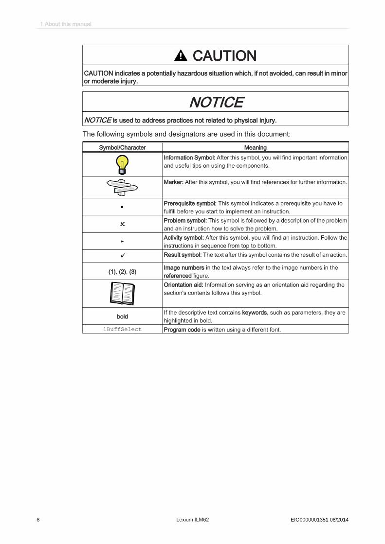
CAUTIONCAUTION indicates a potentially hazardous situation which, if not avoided, can result in minoror moderate injury.
NOTICENOTICE is used to address practices not related to physical injury.
The following symbols and designators are used in this document:
Symbol/Character MeaningInformation Symbol: After this symbol, you will find important informationand useful tips on using the components.
Marker: After this symbol, you will find references for further information.
Prerequisite symbol: This symbol indicates a prerequisite you have tofulfill before you start to implement an instruction.Problem symbol: This symbol is followed by a description of the problemand an instruction how to solve the problem.
► Activity symbol: After this symbol, you will find an instruction. Follow theinstructions in sequence from top to bottom.
ü Result symbol: The text after this symbol contains the result of an action.
(1), (2), (3) Image numbers in the text always refer to the image numbers in thereferenced figure.Orientation aid: Information serving as an orientation aid regarding thesection's contents follows this symbol.
bold If the descriptive text contains keywords, such as parameters, they arehighlighted in bold.
lBuffSelect Program code is written using a different font.
1 About this manual
8 Lexium ILM62 Schneider Electric 08/2014EIO0000001351 08/2014
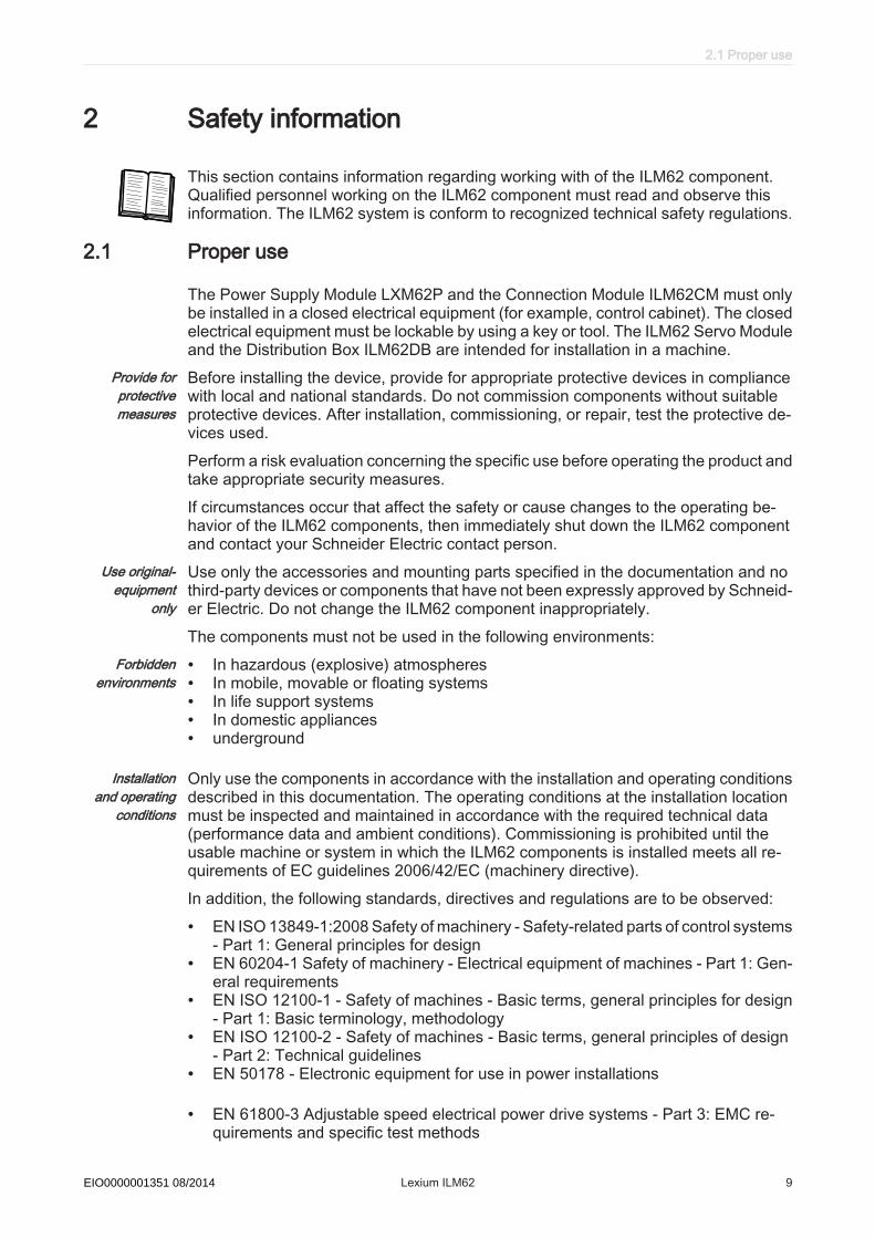
2 Safety information
This section contains information regarding working with of the ILM62 component.Qualified personnel working on the ILM62 component must read and observe thisinformation. The ILM62 system is conform to recognized technical safety regulations.
2.1 Proper use
The Power Supply Module LXM62P and the Connection Module ILM62CM must onlybe installed in a closed electrical equipment (for example, control cabinet). The closedelectrical equipment must be lockable by using a key or tool. The ILM62 Servo Moduleand the Distribution Box ILM62DB are intended for installation in a machine.
Provide forprotectivemeasures
Before installing the device, provide for appropriate protective devices in compliancewith local and national standards. Do not commission components without suitableprotective devices. After installation, commissioning, or repair, test the protective de‐vices used.Perform a risk evaluation concerning the specific use before operating the product andtake appropriate security measures.If circumstances occur that affect the safety or cause changes to the operating be‐havior of the ILM62 components, then immediately shut down the ILM62 componentand contact your Schneider Electric contact person.
Use original-equipment
only
Use only the accessories and mounting parts specified in the documentation and nothird-party devices or components that have not been expressly approved by Schneid‐er Electric. Do not change the ILM62 component inappropriately.The components must not be used in the following environments:
Forbiddenenvironments
• In hazardous (explosive) atmospheres• In mobile, movable or floating systems• In life support systems• In domestic appliances• underground
Installationand operating
conditions
Only use the components in accordance with the installation and operating conditionsdescribed in this documentation. The operating conditions at the installation locationmust be inspected and maintained in accordance with the required technical data(performance data and ambient conditions). Commissioning is prohibited until theusable machine or system in which the ILM62 components is installed meets all re‐quirements of EC guidelines 2006/42/EC (machinery directive).In addition, the following standards, directives and regulations are to be observed:
• EN ISO 13849-1:2008 Safety of machinery - Safety-related parts of control systems- Part 1: General principles for design
• EN 60204-1 Safety of machinery - Electrical equipment of machines - Part 1: Gen‐eral requirements
• EN ISO 12100-1 - Safety of machines - Basic terms, general principles for design- Part 1: Basic terminology, methodology
• EN ISO 12100-2 - Safety of machines - Basic terms, general principles of design- Part 2: Technical guidelines
• EN 50178 - Electronic equipment for use in power installations
• EN 61800-3 Adjustable speed electrical power drive systems - Part 3: EMC re‐quirements and specific test methods
2.1 Proper use
Schneider Electric 08/2014 Lexium ILM62 9EIO0000001351 08/2014

• EN 61800-5-1 Adjustable speed electrical power drive systems - Part 5-1: Safetyrequirements - Electrical, thermal and energy
• The generally applicable local and national safety and accident prevention regu‐lations.
• The rules and regulations on accident prevention and environmental protection thatapply in the country where the product is used.
2.2 Qualification of Personnel
Target audi‐ence
for this manual
Electrical equipment must be installed, operated, serviced, and maintained only byqualified personnel. No responsibility is assumed by Schneider Electric for any con‐sequences arising out of the use of this material.
Qualified per‐son
A qualified person is one who has skills and knowledge related to the construction andoperation of electrical equipment and the installation, and has received safety trainingto recognize and avoid the hazards involved.The qualified personnel must be able to detect possible hazards that may arise fromparameterization, changing parameter values and generally from mechanical, electri‐cal or electronic equipment. The qualified personnel must be familiar with the stand‐ards, provisions and regulations for the prevention of industrial accidents, which theymust observe when working on the drive system.
Designatedsafety func‐
tions
Qualified personnel that work with designated safety functions must be trained ac‐cording to the complexity of the machines and the requirements of the EN ISO13849-1:2008. The training has to include the production process and the relationbetween the designated safety function and the machine.Qualification guidelines are available in the following publication: Safety, Competencyand Commitment: Competency Guidelines for Safety-Related System Practitioners.IEEE Publications, ISBN 0 85296 787 X, 1999.
2.3 Residual risks
Health risks arising from of the ILM62 component have been reduced. However aresidual risk remains, since the ILM62 components work with electrical voltage andelectrical currents.
If activities involve residual risks, a safety message is made at the appropriate points.This includes potential hazard(s) that may arise, their possible consequences, anddescribes preventive measures to avoid the hazard(s). The following types of warningsconcerning residual risks which cannot be assigned to a specific handling. The struc‐ture of a warning instruction is identical to that of a safety label.
2 Safety information
10 Lexium ILM62 Schneider Electric 08/2014EIO0000001351 08/2014

2.3.1 Electrical parts
DANGERHAZARD OF ELECTRIC SHOCK, EXPLOSION, OR ARC FLASH
• Operate electrical components only with a connected protective conductor.• After the installation, verify the fixed connection of the protective conductor to all
electrical devices to ensure that connection complies with the connection dia‐gram.
• Before enabling the device, safely cover the live components to prevent contact.• Do not touch the electrical connection points of the components when the unit is
switched on.• Provide protection against indirect contact (EN 50178).• Disconnect/plug in Plug-in type connectors of the cables, plug-in terminals on the
device and Bus Bar Module only when the system is disconnected from the powersupply.
• Insulate the unused conductors on both ends of the motor cable because ACvoltages in the motor cable can couple to unused conductors.
Failure to follow these instructions will result in death or serious injury.
DANGERELECTRIC SHOCK CAUSED BY HIGH TOUCH VOLTAGE
• Attach the shock protector covers on the outside of the Bus Bar Module combi‐nation.
• Apply power to the device only if the shock protector covers have been attachedon the outside of the Bus Bar Module combination.
Failure to follow these instructions will result in death or serious injury.
DANGERELECTRIC SHOCK CAUSED BY HIGH TOUCH VOLTAGE
• Before working on the device, make sure that it is de-energized.• After unplugging it, do not touch connector CN6 at the power supply, since it still
carries hazardous voltages for one second.• When connecting an N conductor and operating IT networks, only operate the
LXM62 in a control cabinet that cannot be opened without the help of tools. Asan alternative, prevent that the mains plug can be pulled, since this may exposethe pins of the sleeve. If this is also not possible, use an alarm device that indi‐cates hazardous voltages between the phase and the protective earth ground(> 60 V) and therefore, hazardous voltages at the mains plug.
Failure to follow these instructions will result in death or serious injury.
2.3 Residual risks
Schneider Electric 08/2014 Lexium ILM62 11EIO0000001351 08/2014
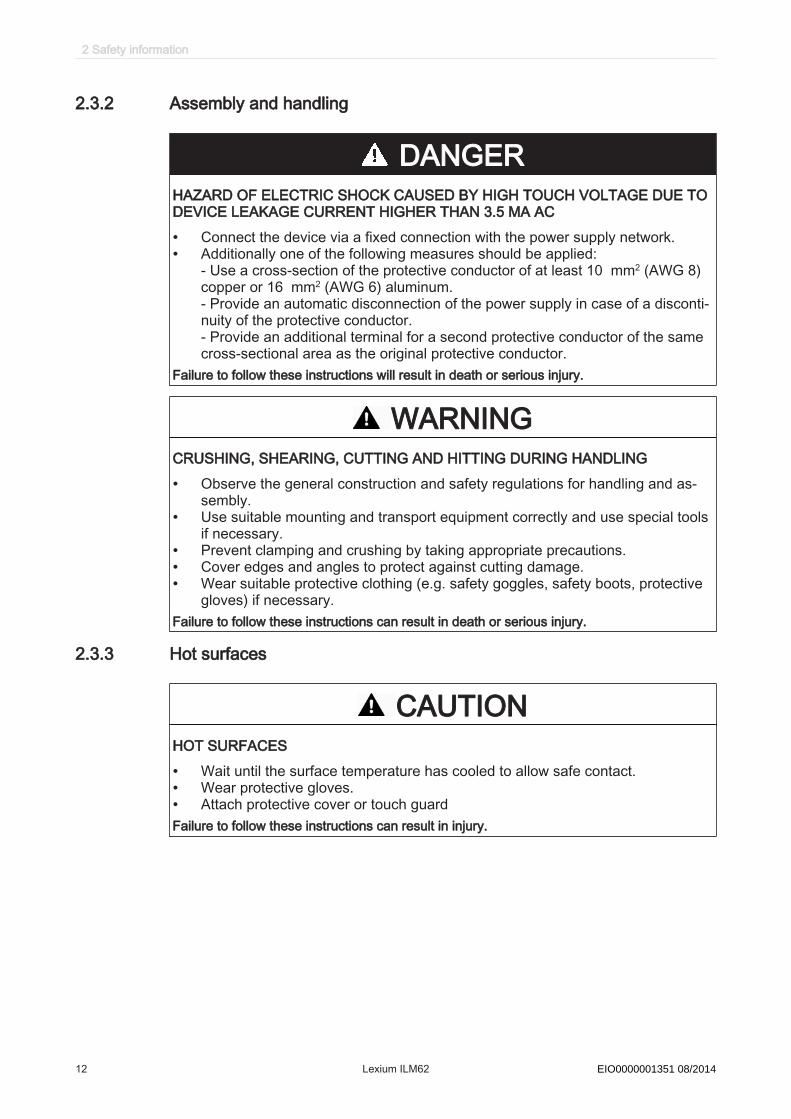
2.3.2 Assembly and handling
DANGERHAZARD OF ELECTRIC SHOCK CAUSED BY HIGH TOUCH VOLTAGE DUE TODEVICE LEAKAGE CURRENT HIGHER THAN 3.5 MA AC
• Connect the device via a fixed connection with the power supply network.• Additionally one of the following measures should be applied:
- Use a cross-section of the protective conductor of at least 10 mm2 (AWG 8)copper or 16 mm2 (AWG 6) aluminum.- Provide an automatic disconnection of the power supply in case of a disconti‐nuity of the protective conductor.- Provide an additional terminal for a second protective conductor of the samecross-sectional area as the original protective conductor.
Failure to follow these instructions will result in death or serious injury.
WARNINGCRUSHING, SHEARING, CUTTING AND HITTING DURING HANDLING
• Observe the general construction and safety regulations for handling and as‐sembly.
• Use suitable mounting and transport equipment correctly and use special toolsif necessary.
• Prevent clamping and crushing by taking appropriate precautions.• Cover edges and angles to protect against cutting damage.• Wear suitable protective clothing (e.g. safety goggles, safety boots, protective
gloves) if necessary.Failure to follow these instructions can result in death or serious injury.
2.3.3 Hot surfaces
CAUTIONHOT SURFACES
• Wait until the surface temperature has cooled to allow safe contact.• Wear protective gloves.• Attach protective cover or touch guardFailure to follow these instructions can result in injury.
2 Safety information
12 Lexium ILM62 Schneider Electric 08/2014EIO0000001351 08/2014

2.3.4 Magnetic and electromagnetic fields
Personnel with pacemakers must not be allowed to work within the vicinity of this typeof equipment.
WARNINGMAGNETIC AND ELECTROMAGNETIC FIELDSDo not work within the vicinity of live conductors and motor permanent magnets if youhave a pacemaker or other similar sensitive medical implants.Failure to follow these instructions can result in death or serious injury.
2.3.5 Hazardous movements
There can be different causes of hazardous movements:
• Missing or incorrect homing of the drive• Wiring or cabling errors• Errors in the application program• Potential component errors• Potential error in the measured value and signal transmitter
Provide for personal safety by primary equipment monitoring or measures. Do not relyonly on the internal monitoring of the drive components. Adapt the monitoring or otherarrangements and measures to the specific conditions of the installation in accordancewith a risk and error analysis carried out by the system manufacturer.
DANGERMISSING OR INADEQUATE PROTECTION DEVICE(S)
• Prevent entry to a zone of operation with, for example, protective fencing, meshguards, protective coverings, or light barriers.
• Dimension the protective devices properly and do not remove them.• Do not make any modifications that can degrade, incapacitate or in any way in‐
validate protection devices.• Before accessing the drives or entering the zone of operation, bring the drives to
a stop.• Protect existing work stations and operating terminals against unauthorized op‐
eration.• Position EMERGENCY STOP switches so that they are easily accessible and
can be reached quickly.• Validate the functionality of EMERGENCY STOP equipment before start-up and
during maintenance periods.• Prevent unintentional start-up by disconnecting the power connection of the drive
using the EMERGENCY STOP circuit or using an appropriate lock-out tag-outsequence.
• Validate the system and installation before the initial start-up.• Avoid operating high-frequency, remote control, and radio devices close to the
system electronics and their feed lines and perform, if necessary, an EMC vali‐dation of the system.
Failure to follow these instructions will result in death or serious injury.
2.3 Residual risks
Schneider Electric 08/2014 Lexium ILM62 13EIO0000001351 08/2014

2.3.6 PELV circuits
The signal voltage and the control voltage of the devices are < 30 Vdc and have tobe designed as PELV circuits. In this range the specification as PELV system, ac‐cording to EN 61800-5-1 contains a protective measure against direct and indirectcontact with dangerous voltage through a implemented safe separation in the system/machine of the primary and the secondary side. We recommend to design the system/machine with a safe separation (PELV Protective-Extra-Low-Voltage).
DANGERHAZARD OF ELECTRIC SHOCK BY INADEQUATE PROTECTIVE SEPARATIONOnly connect devices, electrical components or lines to the signal voltage connectorsof these components that feature a sufficient, protective separation from the con‐nected circuits in accordance with the standards (IEC 61800-5-1: Adjustable speedelectrical power drive systems - safety requirements).Failure to follow these instructions will result in death or serious injury.▶ Achieve a safe separation in the entire process of the electric circuit.
2 Safety information
14 Lexium ILM62 Schneider Electric 08/2014EIO0000001351 08/2014

3 System overviewThe control system consists of several single components, depending on its applica‐tion.
Ethernet, TCP/IP, OPC, FTP, HTTP, SMS, SMTP
sercos + Integrated Safety*
Magelis
HMI
LMC 100C, 101C, 106C, 201C, 212C, 216C, 300C, 400C, 600C
Logic Motion Controllers
SoMachine
Motion
IT/COM
Logic Motion
TM7
Remote I/O
TM7
Remote I/O
TM5 I/O
Multiaxes Servo Drives LXM 62
+ Power Supply Module LXM62P•••
Stand-alone
ServoDrives
LXM 52
Distribution
Box
ILM 62SH3 euqroT H3S
Motor
Linear
Motor
Other field busses:
• Profibus DP
• CAN
• Ethernet/IP
• Profinet
Safety PLC SLCx00*
ILx SD328
BRS3
TeSys ATV 312
ATV 32
= InverterEnable 2-channel (red small square on the device)
+ Connection Module ILM62CM
Figure 3-1: PacDrive 3 System overview
*Safety PLC according to IEC 61508:2010 and EN ISO 13849:2008
3.1 Logic Motion Controller
The LMC (Logic Motion Controller), with a VxWorks real-time operating system, cen‐trally implements the PLC (Programmable Logic Controller) and motion functions. ALMC synchronizes, coordinates and creates the motion functions of a machine for amaximum of:
• 0 Sercos servo drives (LMC 100C)• 4 Sercos servo drives (LMC 101C)• 6 Sercos servo drives (LMC 106C)• 8 Sercos servo drives (LMC 201C)• 12 Sercos servo drives (LMC 212C)• 16 Sercos servo drives (LMC 216C)• 8 Sercos servo drives (LMC 300C)• 16 Sercos servo drives (LMC 400C)• 99 Sercos servo drives (LMC 600C)
3.1 Logic Motion Controller
Schneider Electric 08/2014 Lexium ILM62 15EIO0000001351 08/2014
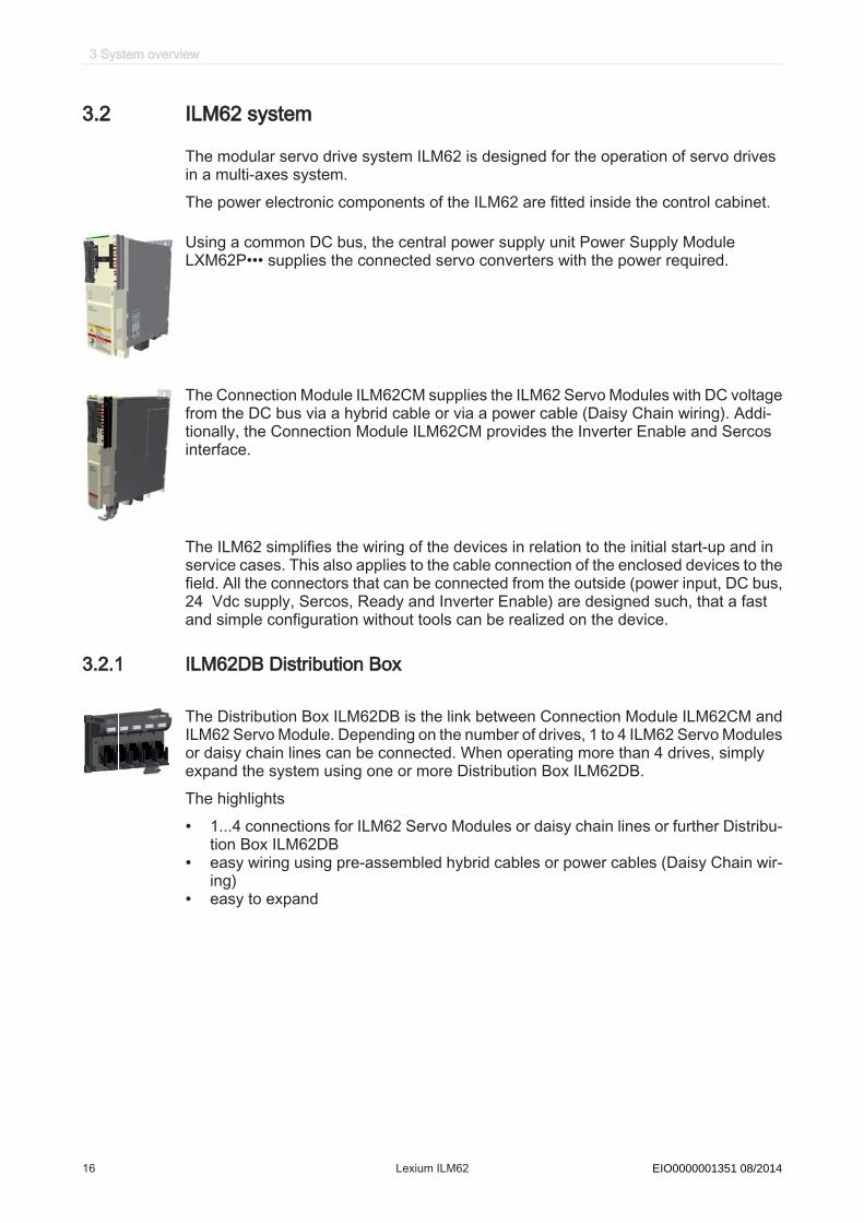
3.2 ILM62 system
The modular servo drive system ILM62 is designed for the operation of servo drivesin a multi-axes system.The power electronic components of the ILM62 are fitted inside the control cabinet.
Using a common DC bus, the central power supply unit Power Supply ModuleLXM62P••• supplies the connected servo converters with the power required.
The Connection Module ILM62CM supplies the ILM62 Servo Modules with DC voltagefrom the DC bus via a hybrid cable or via a power cable (Daisy Chain wiring). Addi‐tionally, the Connection Module ILM62CM provides the Inverter Enable and Sercosinterface.
The ILM62 simplifies the wiring of the devices in relation to the initial start-up and inservice cases. This also applies to the cable connection of the enclosed devices to thefield. All the connectors that can be connected from the outside (power input, DC bus,24 Vdc supply, Sercos, Ready and Inverter Enable) are designed such, that a fastand simple configuration without tools can be realized on the device.
3.2.1 ILM62DB Distribution Box
The Distribution Box ILM62DB is the link between Connection Module ILM62CM andILM62 Servo Module. Depending on the number of drives, 1 to 4 ILM62 Servo Modulesor daisy chain lines can be connected. When operating more than 4 drives, simplyexpand the system using one or more Distribution Box ILM62DB.The highlights
• 1...4 connections for ILM62 Servo Modules or daisy chain lines or further Distribu‐tion Box ILM62DB
• easy wiring using pre-assembled hybrid cables or power cables (Daisy Chain wir‐ing)
• easy to expand
3 System overview
16 Lexium ILM62 Schneider Electric 08/2014EIO0000001351 08/2014
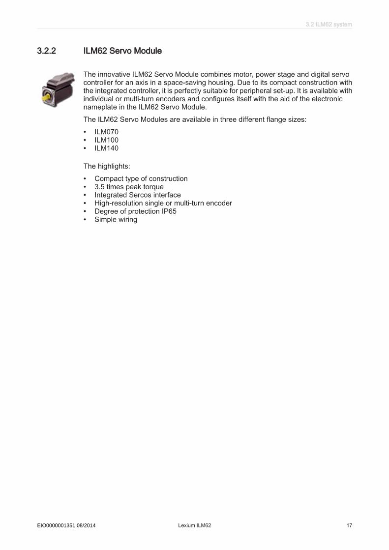
3.2.2 ILM62 Servo Module
The innovative ILM62 Servo Module combines motor, power stage and digital servocontroller for an axis in a space-saving housing. Due to its compact construction withthe integrated controller, it is perfectly suitable for peripheral set-up. It is available withindividual or multi-turn encoders and configures itself with the aid of the electronicnameplate in the ILM62 Servo Module.The ILM62 Servo Modules are available in three different flange sizes:
• ILM070• ILM100• ILM140
The highlights:
• Compact type of construction• 3.5 times peak torque• Integrated Sercos interface• High-resolution single or multi-turn encoder• Degree of protection IP65• Simple wiring
3.2 ILM62 system
Schneider Electric 08/2014 Lexium ILM62 17EIO0000001351 08/2014

3.2.3 ILM62DC•000 Daisy Chain Connector Box
TM
ILM62DCA000
TM
ILM62DCC000
1
ILM62DCB000
111111111111111111111111111111111111111
The ILM62DC•000 Daisy Chain Connector Box is mounted on a standard ILM62 ServoModule in order to enable a daisy chain wiring. The ILM62 Servo Modules can be eitherdirectly connected (see 6.1.7 Wiring as of Connection Module ILM62CM in daisy chainstructure) to the Distribution Box ILM62DB or via a Connection Module ILM62CM.When connecting via a Distribution Box ILM62DB, a larger number of drives can beconnected. At this first Distribution Box ILM62DB another Distribution Box ILM62DBcan be connected. Power (DC bus voltage/24V/Inverter Enable signals) and Sercos signals are distrib‐uted via separate cables. Each ILM62 Servo Module must be extended (see 6.1.4Mechanical mounting) by a Daisy Chain Connector Box. If only one Distribution BoxILM62DB is used, then up to 4 daisy chain lines can be connected to it. If severalDistribution Box ILM62DB are used, then on the first, up to the second to last Distri‐bution Box ILM62DB respectively up to 3 daisy chain lines can be connected and onthe last Distribution Box ILM62DB up to 4 daisy chain lines. A daisy chain line canconsist of up to 9 ILM62 Servo Modules.
The connection between the ILM62 Servo Modules is established as follows (see 6.1.7Wiring as of Connection Module ILM62CM in daisy chain structure):
• Power cable for power distribution (DC bus voltage/24V/Inverter Enable signals)with an M23 connector
• Sercos cable for distribution of the Sercos signals via M12 connector
The following ILM62 Servo Modules can be equipped with the Daisy Chain ConnectorBox in order to implement a daisy chain wiring:
• ILM070••• ILM100••• ILM140••
The Daisy Chain Connector Box is available in the following variants:
• ILM62DCA000 (suitable for ILM070••, ILM100•• and ILM140••)• ILM62DCB000 (suitable for ILM070•• only)• ILM62DCC000 (suitable for ILM100•• only)
3 System overview
18 Lexium ILM62 Schneider Electric 08/2014EIO0000001351 08/2014
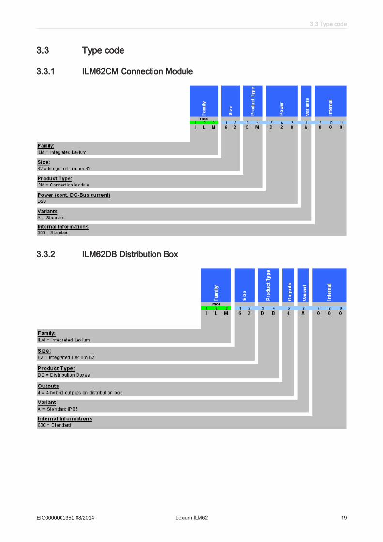
3.3 Type code
3.3.1 ILM62CM Connection Module
3.3.2 ILM62DB Distribution Box
3.3 Type code
Schneider Electric 08/2014 Lexium ILM62 19EIO0000001351 08/2014

3.3.3 ILM62 Servo Module
3 System overview
20 Lexium ILM62 Schneider Electric 08/2014EIO0000001351 08/2014
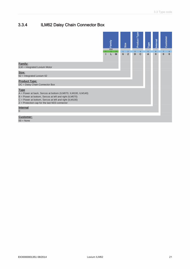
3.3.4 ILM62 Daisy Chain Connector Box
Ty
pe
Inte
rna
l
1 2 3 1 2 3 4 5 6 7 8
I L M 6 2 D C A 0 0 0
Family:
ILM = Integrated Lexium Motor
Size:
62 = Integrated Lexium 62
Product Type:
DC = Daisy Chain Connector Box
Type
A = Power at back, Sercos at bottom (ILM070, ILM100, ILM140)
B = Power at bottom, Sercos at left and right (ILM070)
C = Power at bottom, Sercos at left and right (ILM100)
Z = Protection cap for the last M23 connector
Internal
0
Customer:
00 = None
Fa
mil
y
Siz
e
Pro
du
ct
Ty
pe
Cu
sto
me
r
root
3.3 Type code
Schneider Electric 08/2014 Lexium ILM62 21EIO0000001351 08/2014

3.3.5 ILM62 accessories
Re
s. B
od
y
Fam
ily
Fix
sep
ara
tor
1 2 3 1 2 3 4 5 6 7 8 9
V W 3 E 1 1 4 1 R 0 5 0
Family:
ILM = Integrated Lexium Motor
Type
E = PacDrive 3
Family
1 = Motor / hybrid / power cables
3 = Sercos cables
Drawing reference
064 = Sercos cable between ILM62 Servo Module and ILM62 Servo Module, connector M12/M12 angled
065 = Sercos cable between ILM62CM and ILM62 Servo Module, connector RJ45/M12 angled
141 = Motor / hybrid cable between ILM62CM and ILM62DB4 or ILM62 Servo Module, cable outlet left (Standard)
142 = Motor / hybrid cable between ILM62DB4 and ILM62DB4 or ILM62 Servo Module, cable outlet left on both sides (Standard)
146= Motor / hybrid cable between ILM62CM and ILM62DB4 or ILM62 Servo Module, cable outlet right
147 = Motor / hybrid cable between ILM62CM and ILM62DB4 or ILM62 Servo Module, cable outlet straight
148 = Motor / hybrid cable between ILM62DB4 and ILM62DB4 or ILM62 Servo Module, cable outlet left and right
149 = Motor / hybrid cable between ILM62DB4 and ILM62DB4 or ILM62 Servo Module, cable outlet left and straight
150 = Motor / hybrid cable between ILM62DB4 and ILM62DB4 or ILM62 Servo Module, cable outlet right and straight
151 = Motor / hybrid cable between ILM62DB4 and ILM62DB4 or ILM62 Servo Module, cable outlet straight on both sides
152 = Motor / hybrid cable between ILM62DB4 and ILM62DB4 or ILM62 Servo Module, cable outlet right on both sides
155 = Power cable between ILM62 Servo Module and ILM62 Servo Module, connector M23/M23
156 = Power cable between ILM62DB4 and ILM62 Servo Module, connector D1/M23
157 = Power cable between ILM62CM and ILM62 Servo Module, connector CM/M23
Fixed separator R
Length
xxx = lenght in 0.1 m - refer to catalogue "Motion centric machine automation with PacDrive 3" for available cable lengths
root
Accesso
ries
Len
gth
Dra
win
g
refe
ren
ce
Upon request, additional cable variants are available from your Schneider Electriccontact person.
3 System overview
22 Lexium ILM62 Schneider Electric 08/2014EIO0000001351 08/2014
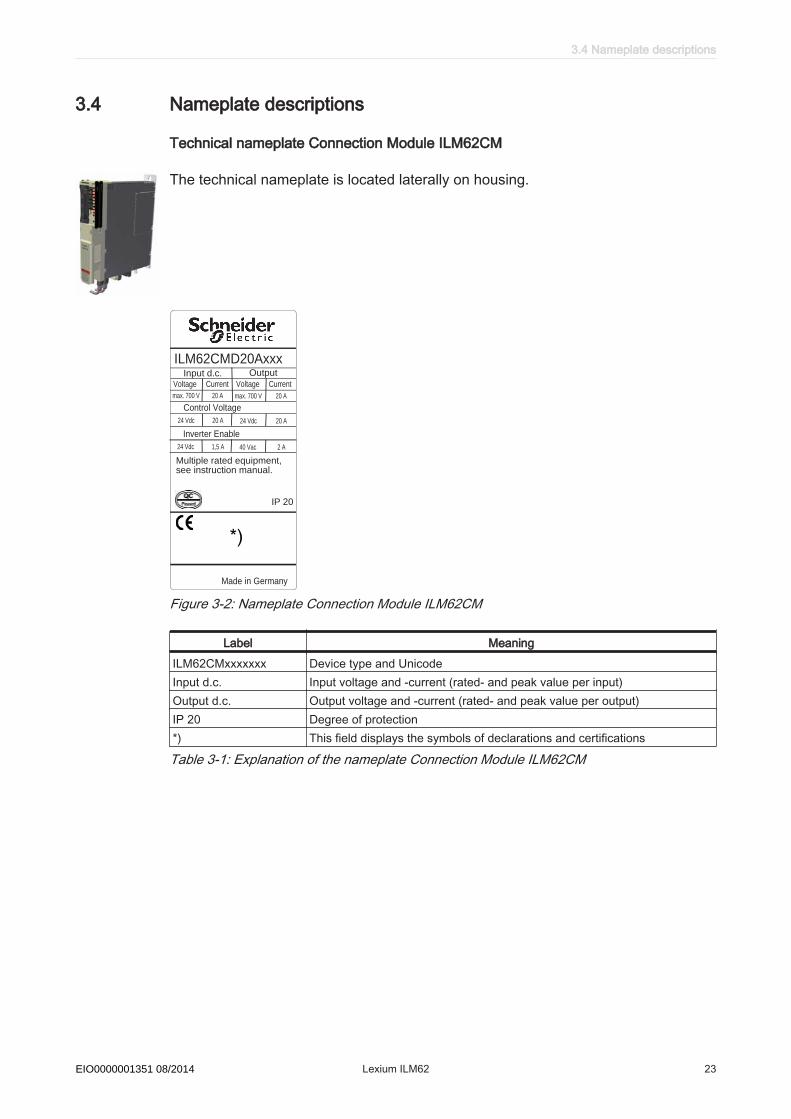
3.4 Nameplate descriptions
Technical nameplate Connection Module ILM62CM
The technical nameplate is located laterally on housing.
ILM62CMD20AxxxOutput
Voltage Current
max. 700 V 20 A
Multiple rated equipment,see instruction manual.
Made in Germany
IP 20
Input d.c.Voltage Current
max. 700 V 20 A
Control Voltage
24 Vdc 20 A24 Vdc 20 A
Inverter Enable
40 Vac 2 A24 Vdc 1,5 A
Figure 3-2: Nameplate Connection Module ILM62CM
Label MeaningILM62CMxxxxxxx Device type and UnicodeInput d.c. Input voltage and -current (rated- and peak value per input)Output d.c. Output voltage and -current (rated- and peak value per output)IP 20 Degree of protection*) This field displays the symbols of declarations and certifications
Table 3-1: Explanation of the nameplate Connection Module ILM62CM
3.4 Nameplate descriptions
Schneider Electric 08/2014 Lexium ILM62 23EIO0000001351 08/2014

Logistic nameplate Connection Module ILM62CM
The logistic nameplate of the Connection Module ILM62CM is located on the top ofthe housing.
Label MeaningILM62xxxxxxxxxx Device type and Unicode907156.0010 Serial numberRS:01 Hardware revision statusDOM Date of manufacture
Table 3-2: Explanation of the logistic nameplate Connection Module ILM62CM
Technical nameplate Distribution Box ILM62DB
ILM62DB4AxxxOutput
Voltage Current
max. 700 V 20 A
Multiple rated equipment,see instruction manual.
Made in Germany
IP 65
Input d.c.Voltage Current
max. 700 V 20 A
Control Voltage
24 Vdc 20 A24 Vdc 20 A
Inverter Enable
40 Vac 2 A40 Vac 2 A
enclosed type 1 rating
Figure 3-3: Technical nameplate Distribution Box ILM62DB
Label MeaningILM62DBxxxxx Device type, see type codeInput d.c. Rated voltage and rated current of the power supplyOutput d.c. Rated voltage and rated current of the power supplyIP 65 Degree of protection*) This field displays the symbols of declarations and certifications
Table 3-3: Explanation of the technical nameplate Distribution Box ILM62DB
3 System overview
24 Lexium ILM62 Schneider Electric 08/2014EIO0000001351 08/2014

Technical nameplate ILM62 Servo Module
Figure 3-4: Nameplate ILM62 Servo Module
Label MeaningILM100xxxxxxxxx Device type, see type codeSN Serial numberInput 1 Rated voltage and rated current of the power supplyInput 2 Rated voltage and rated current of the electronicsType rating Degree of protection of the housing in accordance with Nema 250
and UL 50HW Hardware versionSW Software versionIP Degree of protectionTh-Cl Insulation material class of the motorM0 Standstill torqueMmax Peak torquenN Nominal speed of rotationDOM Date of manufacture
Table 3-4: Explanation of the nameplate ILM62 Servo Module
3.4 Nameplate descriptions
Schneider Electric 08/2014 Lexium ILM62 25EIO0000001351 08/2014
4 Indicators and control elements
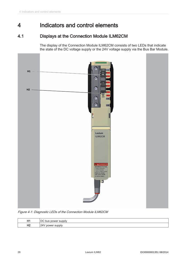
4.1 Displays at the Connection Module ILM62CM
The display of the Connection Module ILM62CM consists of two LEDs that indicatethe state of the DC voltage supply or the 24V voltage supply via the Bus Bar Module.
TM
H1
H2
Figure 4-1: Diagnostic LEDs of the Connection Module ILM62CM
H1 DC bus power supplyH2 24V power supply
4 Indicators and control elements
26 Lexium ILM62 Schneider Electric 08/2014EIO0000001351 08/2014

4.1.1 24Vdc LED
Color State Meaning NotesOFF 24Vdc logic supply inactive 24Vdc voltage < 3V
ON(green)
24Vdc logic supply active 24Vdc voltage ≥ 3V
Table 4-1: 24Vdc LED
4.1.2 DC bus LED
Color State Meaning NotesOFF DC bus supply inactive DC bus voltage < 42 Vdc
ON (red) DC bus supply active DC bus voltage ≥ 42 Vdc
Table 4-2: DC bus LED
The DC bus LED is no clear display for a non-existing DC bus voltage.
4.2 Displays at the Distribution Box ILM62DB
TM
1
3
2
Figure 4-2: Display and operating elements of the Distribution Box ILM62DB
1 Hybrid Connection LED2 DC bus LED3
Protective ground conductor
4.2 Displays at the Distribution Box ILM62DB
Schneider Electric 08/2014 Lexium ILM62 27EIO0000001351 08/2014

4.2.1 DC bus LED
The LED indicates the status of the DC bus voltage.
Color State Meaning NotesOFF DC bus supply inactive DC bus voltage < 42 Vdc
ON (red) DC bus supply active DC bus voltage ≥ 42 Vdc
Table 4-3: DC bus LED
The DC bus LED is no clear sign for a non-existing DC bus voltage.
4.2.2 Hybrid connection LED
Color State Meaning NotesOFF Hybrid connection open
ON Hybrid plug connector connected Applies for hybrid cable or power cable (daisychain wiring).
Table 4-4: Hybrid connection LED
4 Indicators and control elements
28 Lexium ILM62 Schneider Electric 08/2014EIO0000001351 08/2014

4.3 Displays at the ILM62 Servo Module
The display at the ILM62 Servo Module consists of four color LEDs that are used todisplay the status information.
H3
H2
H1
H4
Figure 4-3: Diagnostic LEDs of the ILM62 Servo Module
H1 State LEDH2 Port 1 LEDH3 S3 LEDH4 Port 2 LED
4.3 Displays at the ILM62 Servo Module
Schneider Electric 08/2014 Lexium ILM62 29EIO0000001351 08/2014
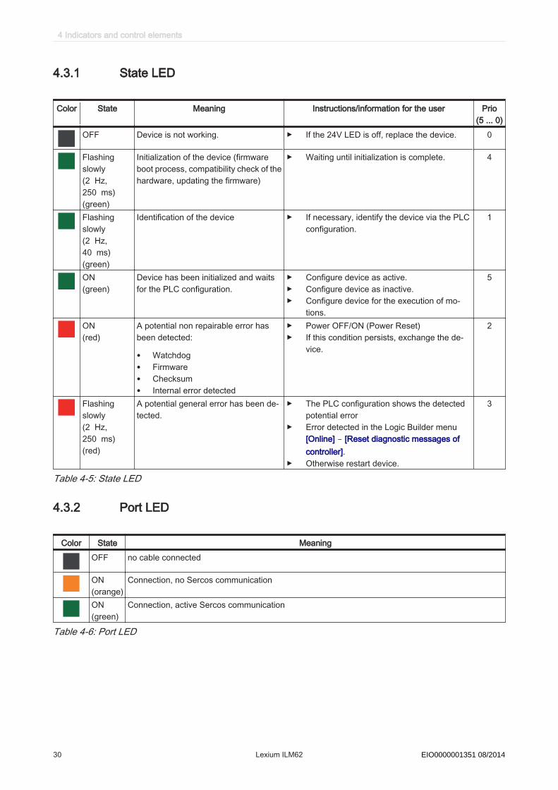
4.3.1 State LED
Color State Meaning Instructions/information for the user Prio(5 ... 0)
OFF Device is not working. ▶ If the 24V LED is off, replace the device. 0
Flashingslowly(2 Hz,250 ms)(green)
Initialization of the device (firmwareboot process, compatibility check of thehardware, updating the firmware)
▶ Waiting until initialization is complete. 4
Flashingslowly(2 Hz,40 ms)(green)
Identification of the device ▶ If necessary, identify the device via the PLCconfiguration.
1
ON(green)
Device has been initialized and waitsfor the PLC configuration.
▶ Configure device as active.▶ Configure device as inactive.▶ Configure device for the execution of mo‐
tions.
5
ON(red)
A potential non repairable error hasbeen detected:
• Watchdog• Firmware• Checksum• Internal error detected
▶ Power OFF/ON (Power Reset)▶ If this condition persists, exchange the de‐
vice.
2
Flashingslowly(2 Hz,250 ms)(red)
A potential general error has been de‐tected.
▶ The PLC configuration shows the detectedpotential error
▶ Error detected in the Logic Builder menu[Online] - [Reset diagnostic messages ofcontroller].
▶ Otherwise restart device.
3
Table 4-5: State LED
4.3.2 Port LED
Color State MeaningOFF no cable connected
ON(orange)
Connection, no Sercos communication
ON(green)
Connection, active Sercos communication
Table 4-6: Port LED
4 Indicators and control elements
30 Lexium ILM62 Schneider Electric 08/2014EIO0000001351 08/2014

4.3.3 S3 LED
Color State Meaning Instructions/information for the user Prio(0 - 3)
off The device is switched off or there is nocommunication due to an interrupted orseparated connection.
Sercos boot-up or hot plug 0
On(green)
Active Sercos connection without an er‐ror detected in the CP4.
- 0.1
Flashing(2 Hz,250 ms)(green)
The device is in Loopback mode.Loopback describes the situation inwhich the Sercos telegrams have to besent back on the same port on whichthey were received.Possible causes:
• Line topology or• Sercos loop break
Workaround:▶ Close ring.Reset condition:▶ Acknowledge error detected in the Logic
Builder menu [Online] - [Reset diagnosticmessage of controller].
▶ Switch from CP0 to CP1 alternatively.Note:If during phase CP1 a line topology or ring breakwas detected (device in loopback mode), the LEDcondition does not change.
2
On(red)
Sercos diagnostic class 1 (DK1) poten‐tial error has been detected on port 1and/or 2. There is no Sercos communi‐cation possible anymore on the ports.
Reset condition:▶ Acknowledge error detected in the Logic
Builder menu [Online] - [Reset diagnosticmessage of controller].
1
Flashing(2 Hz,250 ms)(red)
Communication error at port 1 and/orport 2 has been detected.possible causes:
• Improper functioning of the tele‐gram
• CRC error detected
Reset condition:▶ The PLC configuration shows the detected
potential error▶ Acknowledge error detected in the Logic
Builder menu [Online] - [Reset diagnosticmessage of controller].
0.3
On(orange)
The device is in a communicationsphase CP0 up to and including CP3 orHP0 up to and including HP2. Sercostelegrams are received.
- 0.2
Flashing(4 Hz,125 ms)(orange)
Device identification - 3
Table 4-7: S3 LED
4.3 Displays at the ILM62 Servo Module
Schneider Electric 08/2014 Lexium ILM62 31EIO0000001351 08/2014
5 Planning
5.1 Electromagnetic Compatibility, EMC
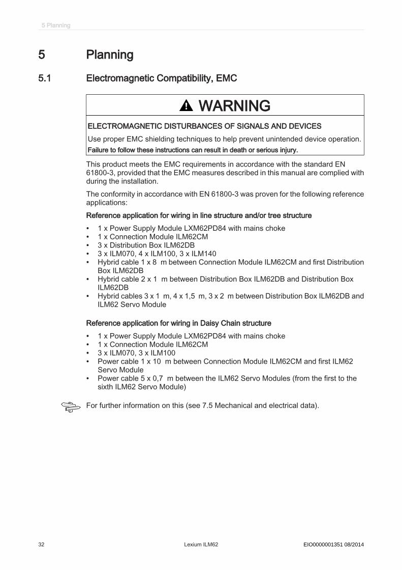
WARNINGELECTROMAGNETIC DISTURBANCES OF SIGNALS AND DEVICESUse proper EMC shielding techniques to help prevent unintended device operation.Failure to follow these instructions can result in death or serious injury.
This product meets the EMC requirements in accordance with the standard EN61800-3, provided that the EMC measures described in this manual are complied withduring the installation.The conformity in accordance with EN 61800-3 was proven for the following referenceapplications:Reference application for wiring in line structure and/or tree structure
• 1 x Power Supply Module LXM62PD84 with mains choke• 1 x Connection Module ILM62CM• 3 x Distribution Box ILM62DB• 3 x ILM070, 4 x ILM100, 3 x ILM140• Hybrid cable 1 x 8 m between Connection Module ILM62CM and first Distribution
Box ILM62DB• Hybrid cable 2 x 1 m between Distribution Box ILM62DB and Distribution Box
ILM62DB• Hybrid cables 3 x 1 m, 4 x 1,5 m, 3 x 2 m between Distribution Box ILM62DB and
ILM62 Servo Module
Reference application for wiring in Daisy Chain structure
• 1 x Power Supply Module LXM62PD84 with mains choke• 1 x Connection Module ILM62CM• 3 x ILM070, 3 x ILM100• Power cable 1 x 10 m between Connection Module ILM62CM and first ILM62
Servo Module• Power cable 5 x 0,7 m between the ILM62 Servo Modules (from the first to the
sixth ILM62 Servo Module)
For further information on this (see 7.5 Mechanical and electrical data).
5 Planning
32 Lexium ILM62 Schneider Electric 08/2014EIO0000001351 08/2014

Enclosure layout
The prerequisite for compliance with the specified limit values is an EMC compatiblelayout. Comply with the following specifications:
EMC measures TargetUse galvanized or chromium-plated sub plates, bond metallic partsacross large surface areas, remove paint layer from contact surfaces.
Good conductivity by surfacearea contact
Ground enclosure, door and sub plates by using grounding strips orgrounding cables with a cross-section of 10 mm2 (AWG 6).
Reduce emission.
Supplement switch devices such as contactors, relays or magneticvalves with interference suppression combinations or spark suppressorelements (e.g. diodes, varistors, RC elements).
Reduces mutual interference
Fit power and control components separately. Reduces mutual interference
Shieldedcables
EMC measures TargetPlace cable shields on the surface, use cable clamps and groundingstrips.
Reduce emission.
At the control cabinet outfeed, connect the shield of all shielded cablesvia cable clamps to the sub plate across large surface areas.
Reduce emission.
Ground shields of digital signal cables on both sides across large surfaceareas or through conducting connector housings.
Reduce interference action onsignal cables, reduce emis‐sions.
Ground shield of analog signal cables directly on the device (signal in‐put), insulate the shield at the other cable end or ground the samethrough a capacitor, such as 10 nF.
Reduce grounding loops bylow frequency interferences.
Use only shielded motor supply cables with a copper braid and at least85% cover, ground shield on both sides across a large surface area.
Specifically discharge interfer‐ence currents, reduce emis‐sions.
Cable routing
EMC measures TargetDo not route fieldbus cables and signal cables together with cabling fordirect and alternating voltages above 60 V in the same cable duct (field‐bus cables can be routed together with signal cables and analog cablesin the same duct). Recommendation: Routing in separated cable cutswith a distance of at least 20 cm (7.84 in.).
Reduces mutual interference
Keep the cables as short as possible. Do not install any unnecessarycable loops, short cable routing from a central grounding point in thecontrol cabinet to the external grounding connection.
Reduce capacitive and induc‐tive interference couplings.
Insert a potential equalization for:
• large surface installation• different voltage infeeds• networking across buildings
Reduce current on cableshield, reduce emissions.
Use fine wire potential equalization conductor. Discharging of high frequencyinterference currents.
If motor and machine are not connected in a conducting fashion, e.g. dueto an insulated flange or a connection not across a full surface, the motormust be grounded via a grounding cable > 10 mm2 (AWG 6) or a ground‐ing strip.
Reduce emissions, increaseinterference resistance.
Use twisted pair for 24 Vdc signals. Reduce interference action onsignal cables, reduce emis‐sions.
5.1 Electromagnetic Compatibility, EMC
Schneider Electric 08/2014 Lexium ILM62 33EIO0000001351 08/2014
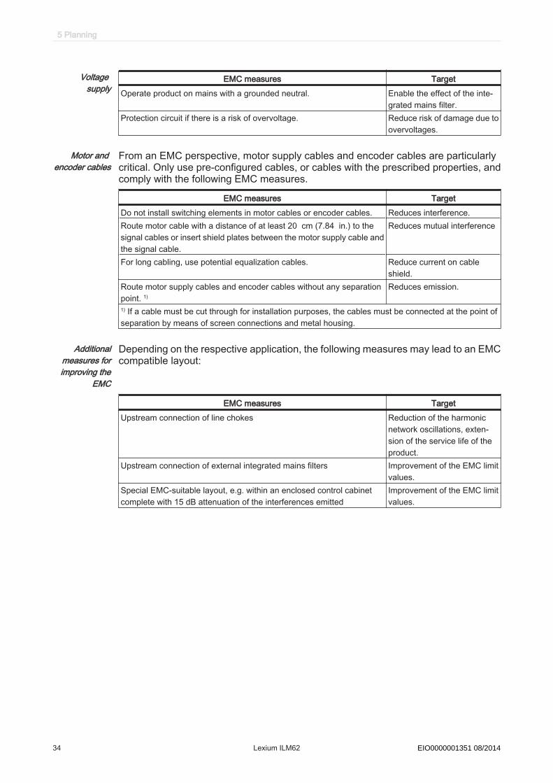
Voltage supply
EMC measures TargetOperate product on mains with a grounded neutral. Enable the effect of the inte‐
grated mains filter.Protection circuit if there is a risk of overvoltage. Reduce risk of damage due to
overvoltages.
Motor and encoder cables
From an EMC perspective, motor supply cables and encoder cables are particularlycritical. Only use pre-configured cables, or cables with the prescribed properties, andcomply with the following EMC measures.
EMC measures TargetDo not install switching elements in motor cables or encoder cables. Reduces interference.Route motor cable with a distance of at least 20 cm (7.84 in.) to thesignal cables or insert shield plates between the motor supply cable andthe signal cable.
Reduces mutual interference
For long cabling, use potential equalization cables. Reduce current on cableshield.
Route motor supply cables and encoder cables without any separationpoint. 1)
Reduces emission.
1) If a cable must be cut through for installation purposes, the cables must be connected at the point ofseparation by means of screen connections and metal housing.
Additionalmeasures forimproving the
EMC
Depending on the respective application, the following measures may lead to an EMCcompatible layout:
EMC measures TargetUpstream connection of line chokes Reduction of the harmonic
network oscillations, exten‐sion of the service life of theproduct.
Upstream connection of external integrated mains filters Improvement of the EMC limitvalues.
Special EMC-suitable layout, e.g. within an enclosed control cabinetcomplete with 15 dB attenuation of the interferences emitted
Improvement of the EMC limitvalues.
5 Planning
34 Lexium ILM62 Schneider Electric 08/2014EIO0000001351 08/2014

5.2 Control cabinet planning
5.2.1 Degree of protection▶ Install components such that a degree of protection corresponding to the actual
operational environment is set up.For more information on the degree of protection of the component (see 7.2 Ambientconditions).The following ambient conditions may damage the components:
• Oil• Moisture• Electromagnetic interference• Ambient temperature• Metal dust deposits
5.2.2 Mechanical and climatic environmental conditions in the control cabinet▶ Observe the climatic and mechanical ambient conditions.
For more information on the general climatic and mechanical environmental con‐ditions according to EN 60721 (see 7.2 Ambient conditions).
▶ Check the technical data of the device as to whether the permitted deviations (e.g.higher shock load or higher temperature) are specified.
5.2 Control cabinet planning
Schneider Electric 08/2014 Lexium ILM62 35EIO0000001351 08/2014

5.2.3 Using Cooling Units
How to proceed when installing a cooling unit:
NOTICEWATER DAMAGE RESULTING FROM CONDENSATIONEnsure proper installation of cooling unit.Failure to follow these instructions can result in equipment damage.
▶ Position the cooling units so that no condensate drips out of the cooling unit ontoelectronic components or is sprayed by the cooling air flow.
▶ Provide specially designed control cabinets for cooling units on the top of thecontrol cabinet.
▶ Design the control cabinet so that the cooling unit fan cannot spray any accumu‐lated condensate onto the electronic components when it restarts after a pause.
▶ When using cooling units, use only well-sealed control cabinets so that warm,humid outside air, which causes condensation, does not enter the cabinet.
▶ When operating control cabinets with open doors during commissioning or main‐tenance, ensure that the electronic components are at no time cooler than the airin the control cabinet after the doors are shut, in order to prevent any condensa‐tion.
▶ Continue to operate the cooling unit even when the system is switched off, so thatthe temperature of the air in the control cabinet and the air in the electronic com‐ponents remains the same.
▶ Set cooling unit to a fixed temperature of 40 °C / 104 °F.▶ For cooling units with temperature monitoring, set the temperature limit to
40 °C / 104 °F so that the internal temperature of the control cabinet does notfall below the external air temperature.
Figure 5-1: Installing a cooling unit
5 Planning
36 Lexium ILM62 Schneider Electric 08/2014EIO0000001351 08/2014

5.3 Wiring notes▶ Only use Schneider Electric devices or certified devices for your application.▶ For connecting of the ILM62 components, only use the cables included within the
scope of delivery.▶ If possible, only use pre-configured cables.For further information (see 5.3.1 Cable characteristics).
▶ If required, order a suitable torque indicator from Schneider Electric.For information on the tightening torques and cable cross-sections (see 7.8 Electricalconnections).Observe the following critical points when wiring:1. Observe the minimum cross-sections of the cables.2. Comply with branch conditions.3. Check shields.4. Ensure proper ground.5. Ensure connection of the motors to the machine ground.6. Prevent any ground loops.7. Do not pull plug-in terminals when under load.8. Use a large shielding area.9. Connect the hybrid or power cable connections and the Sercos cable connections
to the Connection Module ILM62CM according to the connection diagram of themachine manufacturer.For information on the different cable types (see 3.3.5 ILM62 accessories).
10. Do not interchange the EMERGENCY STOP circuits. This has to be observedespecially when two different safety circuits are used for axis A and axis B of theDoubleDrive.
Example:If, for example, two parallel conductors are shown as coming from one point, you maynot run just one conductor and then branch it off at a later point. If it is wired this way,induction loops (interference senders and antennas) as well as interfering potentialshifts may occur.
5.3 Wiring notes
Schneider Electric 08/2014 Lexium ILM62 37EIO0000001351 08/2014

5.3.1 Cable characteristics
Property ValuePermissible voltage hybrid cable 1000 VTemperature range -40 ... +80 °C / -40 ... +176 °FCable diameter 14,8 mm ± 0,3 mmMinimum bending radius 5 x diameter (fixed routing)
10 x diameter (mobile, 5 million bending cycles)Sheath PUR, oil resistant, halogen-free
Table 5-1: Hybrid cable characteristics
Hybrid cable is suitable for use with drag chains.
Property ValuePermissible voltage 1000 VTemperature range -40 ... +80 °C / -40 ... +176 °F (fixed routing)
-25 ... +80 °C / -13 ... +176 °F (mobile)Cable diameter 11.7 mm ± 0.3 mmMinimum bending radius 5 x diameter (fixed routing)
10 x diameter (mobile, 5 million bending cycles)Sheath PUR, oil resistant, halogen-free, flame-retardant
Table 5-2: Cable characteristics of the power cable (daisy chain wiring)
The power cable (daisy chain wiring) is suitable for use with drag chains.
Property ValuePermissible voltage 300 V Temperature range -20 ... +60 °C / -4 ... +140 °FCable diameter 6.7 mm ± 0.2 mmMinimum bending radius 5 x diameter (fixed routing)
10 x diameter (mobile, 5 million bending cycles)Sheath PUR, halogen-free, flame-retardant
Table 5-3: Cable characteristics of the Sercos cable (daisy chain wiring)
Observe the following points when using hybrid, power and Sercos cables:▶ Do not exceed the maximum number of bending cycles of the cable.▶ Observe the installing instructions and the maintenance cycles of this manual.▶ Do not exceed the maximum permitted lifetime of the cables.
5 Planning
38 Lexium ILM62 Schneider Electric 08/2014EIO0000001351 08/2014
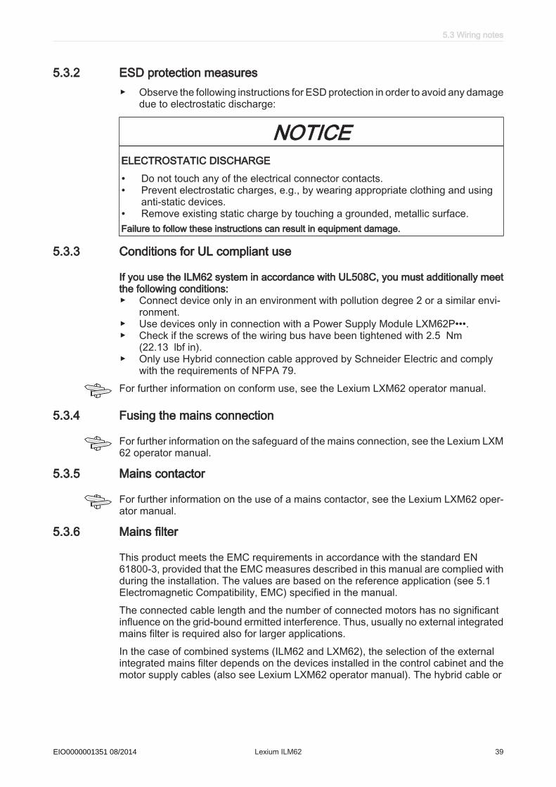
5.3.2 ESD protection measures▶ Observe the following instructions for ESD protection in order to avoid any damage
due to electrostatic discharge:
NOTICEELECTROSTATIC DISCHARGE
• Do not touch any of the electrical connector contacts.• Prevent electrostatic charges, e.g., by wearing appropriate clothing and using
anti-static devices.• Remove existing static charge by touching a grounded, metallic surface.Failure to follow these instructions can result in equipment damage.
5.3.3 Conditions for UL compliant use
If you use the ILM62 system in accordance with UL508C, you must additionally meetthe following conditions:▶ Connect device only in an environment with pollution degree 2 or a similar envi‐
ronment.▶ Use devices only in connection with a Power Supply Module LXM62P•••.▶ Check if the screws of the wiring bus have been tightened with 2.5 Nm
(22.13 lbf in).▶ Only use Hybrid connection cable approved by Schneider Electric and comply
with the requirements of NFPA 79.For further information on conform use, see the Lexium LXM62 operator manual.
5.3.4 Fusing the mains connection
For further information on the safeguard of the mains connection, see the Lexium LXM62 operator manual.
5.3.5 Mains contactor
For further information on the use of a mains contactor, see the Lexium LXM62 oper‐ator manual.
5.3.6 Mains filter
This product meets the EMC requirements in accordance with the standard EN61800-3, provided that the EMC measures described in this manual are complied withduring the installation. The values are based on the reference application (see 5.1Electromagnetic Compatibility, EMC) specified in the manual.The connected cable length and the number of connected motors has no significantinfluence on the grid-bound ermitted interference. Thus, usually no external integratedmains filter is required also for larger applications.In the case of combined systems (ILM62 and LXM62), the selection of the externalintegrated mains filter depends on the devices installed in the control cabinet and themotor supply cables (also see Lexium LXM62 operator manual). The hybrid cable or
5.3 Wiring notes
Schneider Electric 08/2014 Lexium ILM62 39EIO0000001351 08/2014
power cable (with daisy chain wiring) of the ILM62 is not to be considered as motorsupply cable.You can install additional external integrated mains filters if the internal attenuation ofinterferences is not sufficient. For questions on this, please contact your SchneiderElectric partner.
5.3.7 Mains chokes
For further information on the use of line chokes, see the Lexium LXM62 operatormanual.
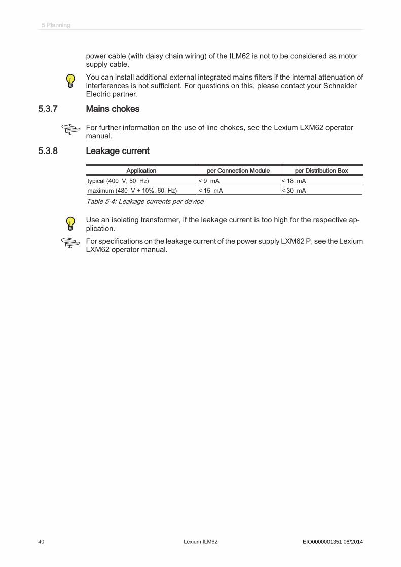
5.3.8 Leakage current
Application per Connection Module per Distribution Boxtypical (400 V, 50 Hz) < 9 mA < 18 mAmaximum (480 V + 10%, 60 Hz) < 15 mA < 30 mA
Table 5-4: Leakage currents per device
Use an isolating transformer, if the leakage current is too high for the respective ap‐plication.For specifications on the leakage current of the power supply LXM62 P, see the LexiumLXM62 operator manual.
5 Planning
40 Lexium ILM62 Schneider Electric 08/2014EIO0000001351 08/2014
5.3.9 Residual current operated protective device
DANGERHAZARD OF ELECTRIC SHOCK CAUSED BY HIGH TOUCH VOLTAGE DUE TODEVICE LEAKAGE CURRENT HIGHER THAN 3.5 MA AC
• Connect the device via a fixed connection with the power supply network.• Additionally one of the following measures should be applied:
- Use a cross-section of the protective conductor of at least 10 mm2 (AWG 8)copper or 16 mm2 (AWG 6) aluminum.- Provide an automatic disconnection of the power supply in case of a disconti‐nuity of the protective conductor.- Provide an additional terminal for a second protective conductor of the samecross-sectional area as the original protective conductor.
Failure to follow these instructions will result in death or serious injury.
For further information on fault current protection equipment, see the Lexium LXM62operator manual.
5.3 Wiring notes
Schneider Electric 08/2014 Lexium ILM62 41EIO0000001351 08/2014
5.4 Functional safety
5.4.1 Process minimizing risks associated with the machine
The goal of designing machines safely is to protect people. The risk associated withmachines with electrically controlled drives comes chiefly from moving machine parts.
Hazard and risk analysisOn the basis of the system configuration and utilization, a hazard and risk analysis canbe carried out for the system (for example, according to EN ISO 14121 or EN ISO13849-1:2008). The results of this analysis must be considered when using the “In‐verter Enable” safety function. The circuit resulting from this analysis may deviate fromthe application examples. For example, additional safety components may be re‐quired. In principle, the results from the hazard and risk analysis have priority.The EN ISO 13849-1:2008 Safety of machinery - Safety-related parts of control sys‐tems - Part 1: General principles for design describes an iterative process for the se‐lection and design of safety-related parts of controllers to reduce the risk to the ma‐chine to a reasonable degree:This is how you perform risk assessment and risk minimization according to EN ISO14121:1. Define the boundary of the machine.2. Identifying risks associated with the machine.3. Assessing risks.4. Evaluating risks.5. Minimizing risks by:
- intrinsically safe design- protective devices- user information (see EN ISO 12100-1)
6. Designing safety-related controller parts (SRP/CS, Safety-Related Parts of theControl System) in an interactive process.
This is how you design the safety-related controller parts in an interactive process:▶ Identifying necessary safety functions that are executed via SRP/CS (Safety-Re‐
lated Parts of the Control System).▶ Determining required properties for each safety function.▶ Determining the required performance level PLr.▶ Identifying safety-related parts executing the safety function.▶ Determining the performance level PL of the afore-mentioned safety-related parts.▶ Verifying performance level PL for the safety function (PL ≥ PLr).▶ Checking, if all requirements have been met (validation).Additional information is available on www.schneider-electric.com.
5 Planning
42 Lexium ILM62 Schneider Electric 08/2014EIO0000001351 08/2014
5.4.2 Inverter Enable function
Functional Description
With the Inverter Enable function (IE) you can bring drives to a safe stop. This InverterEnable function relates to the components
• Connection Module ILM62CM• Distribution Box ILM62DB• ILM62 Servo Module
The Inverter Enable function requires further components, e.g. emergency stop, safetyswitching unit (optional) and connections. The following chapter describes the correctuse of the Inverter Enable function.The Inverter Enable function must be used correctly to enable proper operation. Nev‐ertheless, the accidental loss of the Inverter Enable function cannot be ruled out. Suchlosses are only restricted to the upper limit required by the relevant safety standards.(see 5.4.9 Safety standards) This is expressed by the following characteristic values:
• PFH and SFF according to EN 61508:2010• MTTF_d and DC_avg according to EN ISO 13849-1:2008
In the sense of the relevant standards, the requirements of the stop category 0 (SafeTorque Off, STO) and stop category 1 (Safe Stop 1, SS1) can be met. Both categorieslead to a torque-free motor while SS1 takes this state after a predefined time. As aresult of the hazard and risk analysis, it may be necessary to choose an additionalbrake as a safety option (e.g. for hanging loads).
5.4 Functional safety
Schneider Electric 08/2014 Lexium ILM62 43EIO0000001351 08/2014

Scope of operation (designated safety function)
The Inverter Enable function relates to Connection Module ILM62CM, Distribution BoxILM62DB and ILM62 Servo Module, hereinafter referred to as "ILM62 system".
The function is selected via a signal(pair) at the input of the Connection ModuleILM62CM (2), which is forwarded to all drives (7) of the Connection Module ILM62CMnetwork. The supply voltage (AC) needs not be interrupted (see figure below).
1
2
4
5
6
7
IE
3
AC
Figure 5-2: ILM62 system with emergency stop
1 control cabinet2 Connection Module ILM62CM3 Contactor4 Emergency stop switch5 Safety switching device (e.g. Preventa XPS AV)6 Distribution Box ILM62DB7 ILM62 Servo Module
Operating prin‐ciple
The Inverter Enable function safely switches off the motor torque. It is sufficient to seta logical zero at the function input. There is no need to interrupt the power supply.Standstill, however, is not monitored.
Safestate
InverterEnable is synonymous with "Safe Torque Off (STO)" according to EN61800-5-2. This torque-free state is automatically entered when potential errors aredetected and is therefore the safe state of the drive.
Mode of opera‐tion
By setting a logical one for the Inverter Enable input at the Connection ModuleILM62CM, the power stage control of all Connection Module ILM62CM connected tothis ILM62 Servo Modules become possible (necessary condition). If, on the otherhand, this input is set to a logical zero, the power supply at the Inverter Enable inputis interrupted and no torque can be established in the connected . This Inverter Enableinput has a redundant design (DC voltage from which the generates AC voltage whichis fed to the hybrid cable or power cable (in case of daisy chain wiring)). The failure ofone of the two channels already results in the logical zero. When the power supply is
5 Planning
44 Lexium ILM62 Schneider Electric 08/2014EIO0000001351 08/2014

cut off, the power stage becomes de-energized, and an diagnostic message is gen‐erated. The motor can no longer generate torque and stops unbraked.You can use the InverterEnable function to implement the control function "Stoppingin case of emergency" (EN 60204-1) for stop categories 0 and 1. Use a suitable ex‐ternal safety circuit to prevent the unexpected restart of the drive after a stop, as re‐quired in the machine directive.
Stopcategory 0
In stop category 0 (Safe Torque Off, STO) the drive stops in an uncontrolled manner.If this means a hazard to your machine, you must take suitable measures (see hazardand risk analysis).
Stopcategory 1
For stops of category 1 (Safe Stop 1, SS1) you can request a controlled stop via thePacDrive Controller. The controlled stop by the PacDrive Controller is not safe, notmonitored and not guaranteed to work in case of power outage or a potential error.The final switch off in the safe state is ensured by switching off the "Inverter Enable"input. This has to be implemented by means of an external safety switching devicewith safe delay (see application proposal).
Executemuting
Proceed as follows to deactivate the InverterEnable function:
WARNINGUNINTENDED AXIS MOVEMENT
• Ensure that access to the zone of operation is restricted from personnel whilethere remains a residual charge on the DC bus.
• Wait 15 minutes after removing power (switching off) to allow the DC buscapacitors to discharge.
Failure to follow these instructions can result in death or serious injury.
▶ You can deactivate the Inverter Enable function by using the optional moduleDIS1.
The safe state can only be achieved if the power supply is switched off.▶ To avoid misconfigurations, you now have to define the configuration that is to be
used with the parameter InverterEnableConfig of the ILM62 Servo Modulein the PLC configuration.
If the set mode does not match the real configuration of the ILM62 Servo Module, thenthe diagnostic message 8978 "InverterEnableConfig invalid" with "Ext. diagnostic =x(HW)!=y(Cfg)" is triggered. The drive does not switch to control mode as long as theconfiguration is wrong. The error can only be acknowledged if the set InverterE-nableConfig corresponds to the real configuration. This can be used to divide thedrives on a Connection Module ILM62CM in two groups if it is technically not possibleto use two Connection Module ILM62CM for the two groups in the existing machine.
5.4 Functional safety
Schneider Electric 08/2014 Lexium ILM62 45EIO0000001351 08/2014

If only some of the drives attached to a Connection Module ILM62CM (1) are to be putin the safe state, this can be achieved by the configuration of the drives. This can beof interest e.g. for cleaning modes (6). If an optional module DIS1 (9) is set, then theIE signal will be ignored. To implement the emergency stop, the supply voltage on theConnection Module ILM62CM must be interrupted; see illustration below.
5
2
3
6
7
85
9
IE
4
AC
1
1 Connection Module ILM62CM2 control cabinet3 Emergency stop switch4 Contactor5 Safety switching device (e.g. Preventa XPS AV)6 Switch: Operating mode (normal/cleaning)7 Distribution Box ILM62DB8 ILM62 Servo Module (without DIS1)9 ILM62 Servo Module (with DIS1)
Table 5-5: Implementation of "Emergency stop" and "Cleaning mode iwith Inverter Enable" intwo protective circuits
ILM Cleaning Emergency stop Parameter InverterEna‐bleConfig
ILM62 Servo Modulewithout DIS1 (8)
Torque-free motor Torque-free motor Standard/1
ILM62 Servo Modulewith DIS1 (9)
- Torque-free motor Off/0
5 Planning
46 Lexium ILM62 Schneider Electric 08/2014EIO0000001351 08/2014

Validity of the safety caseThe safety case for the Inverter Enable function of the ILM62 is identified and definedby the standards listed in chapter "Safety standards". The safety case for the InverterEnable function of the ILM62 system applies to the following hardware codes:
Unicode Hardware code:ILM 070/xx xxxxxxxxx1xxILM 100/xx xxxxxxxxx1xxILM140/xx xxxxxxxxx1xxDIS1 1ILM62CM xxxxxx1xxILM62DB xxxxxx1xx
For questions on this, please contact your Schneider Electric partner.
Interface and controlThe Inverter Enable function is operated via the switching thresholds of the InverterEnable-input (IE_p1/IE_p2 at Pin1/Pin2, IE_n1/IE_n2 at Pin3/Pin4) of the ConnectionModule ILM62CM.
• Max. downtime: 500µs at UIE > 20V with dynamic control• Max. test pulse ratio: 1Hz • STO active: -3V ≤ UIE ≤ 5V • Power stage active: 18V ≤ UIE ≤ 30V
Technical data and information on the electrical connections of the ILM62 system orthe Connection Module ILM62CM can be found under of this operating instruction.
Response timeResponse timewith InverterEn‐
able function
The maximum response time until switch off with the Inverter Enable function is5 ms. This is the time from the corresponding change of the Inverter Enable input atthe Connection Module ILM62CM to the torque-free motor (Safe Torque Off, STO).
Muting re‐sponse time
The Muting response time for switching off (i.e. without the Inverter Enable function)depends on the load on the machine and has to be determined from the application.The axes without Inverter Enable function become torque-free via the mains contactorand come to a stop.
5.4 Functional safety
Schneider Electric 08/2014 Lexium ILM62 47EIO0000001351 08/2014

5.4.3 Setup, installation, and mounting
Prevent possible functional disorder and avoid overvoltageThe following measures avoid overvoltages and prevent a possible functional disorderthrough conductive pollution or parts falling into the device:
DANGERHAZARD OF ELECTRIC SHOCK, EXPLOSION, OR ARC FLASH
• Install Connection Module ILM62CM in a control cabinet or housing of at leastIP 54.
• Comply with the clearances and creepage distances according to EN 50178.• ILM62 must only be operated with power supplies certified according to EN
60950 or EN 50178 (so-called "safe voltage outputs").Failure to follow this instruction will result in death or serious injury.
These power supply units do not deliver an overvoltage over 120 Vdc for morethan 120ms or no permanent overvoltage over 60 Vdc.
▶ Only operate the drive system with approved, specified cables, accessories- andspare parts by Schneider Electric.
Avoid unintentional restart
DANGERUNINTENTIONAL RESTART OF THE MOTOR
• Ensure that a restart of the motor is not possible after a return of power or thetripping of a functional safety device unless preceded by a deliberate enable sig‐nal from the system.
• Ensure that the enable signal meets the specified safety criteria (see 5.4.4 Ap‐plication proposals).
Failure to follow these instructions will result in death or serious injury.
To avoid that the system is in a continuous "safe state", proceed as follows:▶ Observe the specified maximum configuration (number of devices, network struc‐
ture and cable length), or else a power drop of the InverterEnable signal will occurover the cable length and therefore the system will be in the safe state continu‐ously.
▶ Connect per Connection Module ILM62CM a maximum of 45 ILM62 Servo Mod‐ules.For further information on the dimensions of the maximum system extension forwiring in line structure or tree structure (see 6.1.6 Wiring as of Connection ModuleILM62CM in line structure or tree structure) or daisy chain structure (see 6.1.7Wiring as of Connection Module ILM62CM in daisy chain structure):
Perform muting with the optional module DIS1How to install the optional module DIS1:▶ Open main switch.▶ Prevent main switch from being switched back on.▶ Remove the Transparent cover plate on the motor.▶ Remove plugged in jumpers J1 and J2 (see figure).
5 Planning
48 Lexium ILM62 Schneider Electric 08/2014EIO0000001351 08/2014
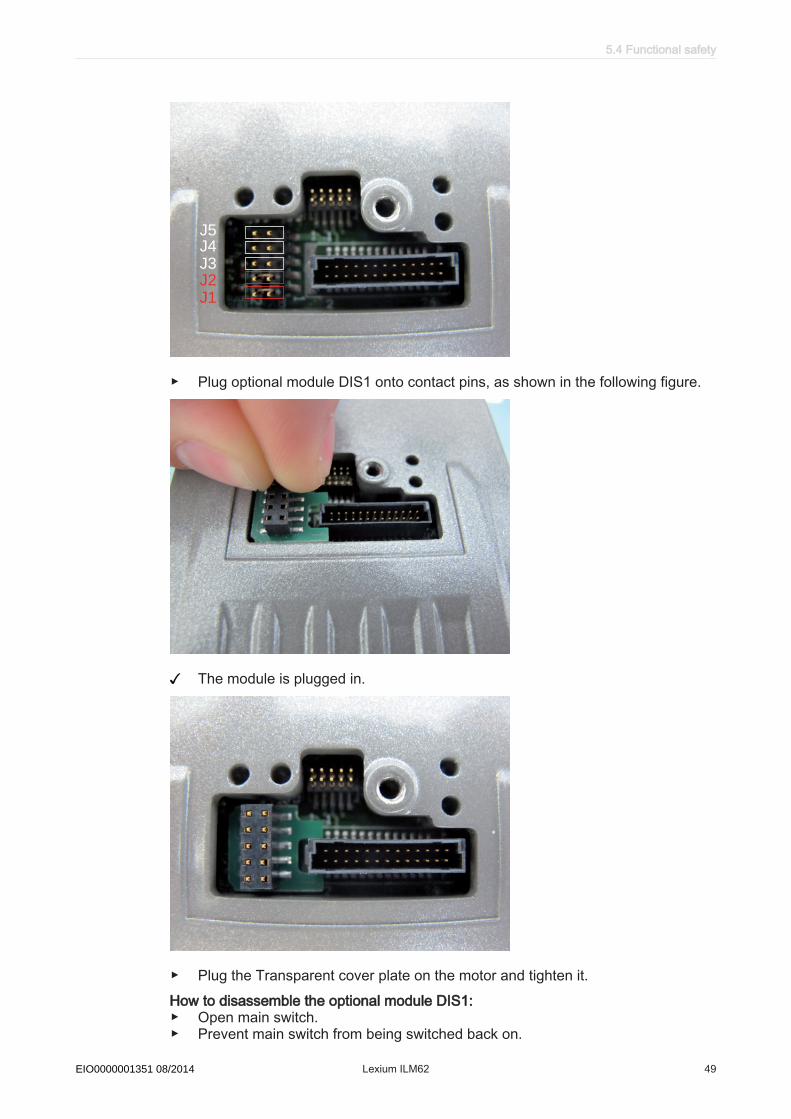
J1
J2
J3
J4
J5
▶ Plug optional module DIS1 onto contact pins, as shown in the following figure.
The module is plugged in.
▶ Plug the Transparent cover plate on the motor and tighten it.How to disassemble the optional module DIS1:▶ Open main switch.▶ Prevent main switch from being switched back on.
5.4 Functional safety
Schneider Electric 08/2014 Lexium ILM62 49EIO0000001351 08/2014

▶ Remove the Transparent cover plate on the motor.▶ Remove the optional module DIS1.▶ Plug in jumpers J1 and J2 (see figure).
J1
J2
J3
J4
J5
▶ Plug the Transparent cover plate on the motor and tighten it.
5 Planning
50 Lexium ILM62 Schneider Electric 08/2014EIO0000001351 08/2014

5.4.4 Application proposals
There is one application proposal to implement the safe stop of category 1 (SS1):
• EL-1122-05-xx: Inverter Enable circuit Connection Module ILM62CM/ILM62 ServoModule using the PacDrive Controller LMC•00C with safety switch device for anemergency stop circuit
Notes on application proposalsGeneral • All application proposals provide for a protected Inverter Enable-wiring (control
cabinet IP54) from the safety switch device to the Connection Module ILM62CM,as faults need to be ruled out.
• Protection against automatic restart is ensured by the external safety switch device.
Notes onEL-1122
The mains contactor in this circuit suggestion is not necessary for functional safetypurposes. It is, however, used in the application proposal for the device protection ofthe Power Supply Module LXM62P or the components connected to it.
5.4 Functional safety
Schneider Electric 08/2014 Lexium ILM62 51EIO0000001351 08/2014
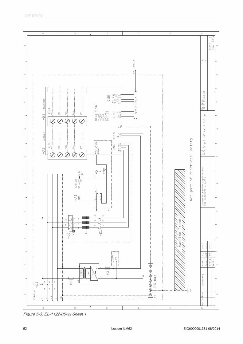
A B C D E F
A B C D FE
65
43
21
87
09
54
32
10
69
87
Bl.
= +
von
Blatt
Vert.
DatumName
Z. Art.
Erst.
Gepr.
Freig.
Änderung
SE
APP
WR
L1
L2
L3
PE
N
+24V
0V WD &rdy
+24V
0V
InverterEnable Application
Z. Art.
2
1
4
3
6
5-Q1
-F2
+-
24V
230V
1 24
12
-G
LMC
CN1
CN124V0V
WD1
WD2
LMC WD
-A1
-F3
-L1
2 1
4 3
6 5-K1
1
Hybrid Cable
SafeStop 1 (SS1)withE-Stop
22.07.11
I >I >I >
1
3
5
2
4
6
-Q2
2
EL-1122-05-01
for PacDrive 3 ILM62
PE bar
PE
Cabinet PE
to ILM62DB
28.07.11
28.07.11
Not part of functional safety
CN1
CN4
CN5
CN6
PE
DC-
DC+
24V
0V
L1L2L3
rdy1
rdy2
PE
24V0V
PE
LXM62P
-A2
CN1
CN8
CN7CN6
PE
DC-
DC+
24V
0V
DC+PEDC-
IE_p1
IE_p2
IE_sigIE_ref
IE_n1
IE_n2
0V_int1
0V_int2
24V_out0V_out
ILM62CM
-A3
Machine frame
Figure 5-3: EL-1122-05-xx Sheet 1
5 Planning
52 Lexium ILM62 Schneider Electric 08/2014EIO0000001351 08/2014

A B C D E F
A B C D F
Bl.
= +
E
von
Blatt
65
43
21
87
09
54
32
10
69
87
Vert.
DatumName
Z. Art.
Z. Art.
Erst.
Gepr.
Freig.
Änderung
SE
WR
WD &
rdy
+24V
0V
+24V
Not part of functional safety
-F1
OFF
1 2
3 4
-S2
E-STOP
11
12
21
22
-S1
START
13
14
-S3
PE
I_MainsWatch
I_InvEnableActive
I_EmergencyStop
O_MainsContactor
LMC
-A1
0V
+24V
A1S13
S14
03
13
23
37
47
57
Y+Y64Y74
85
84
83
42
41
40
93Y
2A
Y84
S21S31
S22
S32
S34
S11S12
S33
Y40
Error
K1/K2
K3/K4
K4
K3
K1
K2
+24V
PREVENTAXPS-AV 11113Z002
-K3
2
22.07.11
APP
Safe Stop 1 (SS1) with E-Stop
Inverter-Enable Application
A1
A2
-K2
13
14
-K2
A1
A2
-K1
21
22
-K1
LMC
WD
0V
24V
Part of functional safety
vcc_ie
Po
we
r S
tag
e
Dri
ve
r
Su
pp
ly
IE_sig
IE_ref
ILM62
-A5
vcc_ie
Po
we
r S
tag
e
Dri
ve
r
Su
pp
ly
IE_sig
IE_ref
ILM62
-A6
vcc_ie
Po
we
r S
tag
e
Dri
ve
r
Su
pp
ly
IE_sig
IE_ref
ILM62
-A7
2
for PacDrive 3 ILM62
Part of functional safety
28.07.11
28.07.11
vcc_ie
Po
we
r S
tag
e
Dri
ve
r
Su
pp
ly
IE_sig
IE_ref
ILM62
-A8
CN6
CN8
DC
AC
0V_INT
IE_n1
IE_p2
IE_n2
0V_int1
0V_int2
IE_sig
IE_ref
IE_p1
ILM62CM
-A3
LXM62P
rdy
IE_ref
IE_sig
ILM62DB
-A4
Figure 5-4: EL-1122-05-xx Sheet 2
5.4 Functional safety
Schneider Electric 08/2014 Lexium ILM62 53EIO0000001351 08/2014

5.4.5 Commissioning▶ Carry out a functional test of the STO function for all drives that need the safety
function.▶ Especially check the correct application of the axes without Inverter Enable func‐
tion.▶ Complete installation in accordance with the EMC regulations and further speci‐
fications in the device operating manuals.▶ Afterwards commission the drive systems.
5.4.6 Best Practices and Prevention of Misuse
At machine start-up, the connected drives are normally outside the range of vision ofthe machine personnel and cannot be monitored directly.
WARNINGUNSUPERVISED MACHINE START-UPOnly start the machine if there are no persons within the working area of movingmachine components and when the machine can be operated safely.Failure to follow these instructions can result in death or serious injury.
Checkplugconnections
▶ Check all terminals, connectors and other connections on all system componentsfor correct and firm fit.
▶ Only use robust connectors and secure fixings.▶ Check the protective earth ground 24Vdc PELV supply.▶ Check the wiring of the safety function to the axes to avoid an interchange of the
IE_sig and IE_ref inputs as well as the 24V supply.▶ Use coded connectors and perform a commissioning test (see 6.1 Commission‐
ing).▶ Use only suitable transport packaging to forward or return individual devices.
Acting ofexternal
forces
The safe state of the motor is the torque-free output shaft. If external forces act uponthe output shaft, it will not necessarily maintain its position. Take additional precautionsif this is one of the safety targets of the hazard and risk analysis.
Hanging &pullingloads
WARNINGUNINTENDED MOVEMENT OF THE AXIS.
• Do not use the internal holding brake as a safety function.• Only use specified external brakes as safety function.Failure to follow these instructions can result in death or serious injury.
▶ If the safe suspension of hanging / pulling loads (safe brake control) is a safetyobjective for the machine, then you can only achieve this objective by using anappropriate external brake as a safety function.
The device does not provide its own safe output to connect an external safety brake.
5 Planning
54 Lexium ILM62 Schneider Electric 08/2014EIO0000001351 08/2014
5.4.7 Maintenance
As the Inverter Enable function has been designed for a defined lifetime (see 5.4.9Safety standards), no routine checks are necessary to maintain or verify functionalsafety. After this lifetime has elapsed a statement about the Inverter Enable functioncannot be made due to the aging of the component. If you want to ensure the func‐tionality in terms of safety standards and product liability after this period, you need toreplace the device that includes the safety function.Subject the device to a complete function test after replacement.
Keep a logbook for tracing the maintenance history of the machine and note the re‐placed components (as per EN 62061:2005).See the "Installation and Maintenance" of this operating instruction chapter for infor‐mation about initial start-up and maintenance.
5.4.8 Physical environment
The system is not protected against physical or chemical sources of danger by anydesign features. Possible sources of danger include:
• toxic,• explosive,• corrosive,• highly reactive, or• inflammable types.
WARNINGLOSS OF THE INVERTER ENABLE FUNCTION
• Observe and conform to the ambient, storage and transport temperatures of theindividual components indicated in the operating manuals of the components.
• Prevent the formation of moisture during the operation, storage and transport ofindividual components.
• Conform to the vibration and shock requirements specified in the operating man‐uals for the components when operating, storing and transporting system com‐ponents.
Failure to follow these instructions can result in death or serious injury.
In principle, all plugs and plug-in connectors which include InverterEnable must bedesigned according to IP54 or higher. Control cabinet devices, such as, a ConnectionModule ILM62CM, do not possess this high protection class and are therefore onlyintended for use in environments according to IP54 or higher (e.g. control cabinets).
5.4 Functional safety
Schneider Electric 08/2014 Lexium ILM62 55EIO0000001351 08/2014
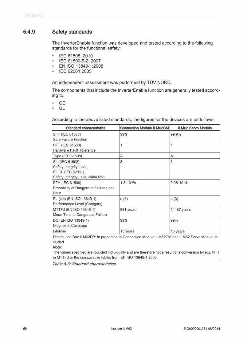
5.4.9 Safety standards
The InverterEnable function was developed and tested according to the followingstandards for the functional safety:
• IEC 61508: 2010• IEC 61800-5-2: 2007• EN ISO 13849-1:2008• IEC 62061:2005
An independent assessment was performed by TÜV NORD.The components that include the InverterEnable function are generally tested accord‐ing to
• CE• UL
According to the above listed standards, the figures for the devices are as follows:
Standard characteristics Connection Module ILM62CM ILM62 Servo ModuleSFF (IEC 61508)Safe Failure Fraction
99% 99.9%
HFT (IEC 61508)Hardware Fault Tolerance
1 1
Type (IEC 61508) A ASIL (IEC 61508) Safety Integrity LevelSILCL (IEC 62061)Safety Integrity Level claim limit
3 3
PFH (IEC 61508) Probability of Dangerous Failures perHour
1.3*10-9/h 0.08*10-9/h
PL (cat) (EN ISO 13849-1) Performance Level (Category)
e (3) e (3)
MTTFd (EN ISO 13849-1) Mean Time to Dangerous Failure
881 years 14487 years
DC (EN ISO 13849-1) Diagnostic Coverage
99% 99%
Lifetime 15 years 15 yearsDistribution Box ILM62DB: in proportion to Connection Module ILM62CM and ILM62 Servo Module in‐cludedNote:The values specified are rounded individually and are therefore not a result of a conversion by e.g. PFHin MTTFd or the comparative tables from EN ISO 13849-1:2008.
Table 5-6: Standard characteristics
5 Planning
56 Lexium ILM62 Schneider Electric 08/2014EIO0000001351 08/2014

5.5 Special Conditions
5.5.1 Low air pressure
If the installation altitude exceeds the specified rated installation altitude, the perform‐ance of the entire system is reduced.Power Supply Module LXM62P•••
Derating of Mains Input Current vs. Installation altitude
10
20
30
40
50
60
70
80
90
100
110
0 500 1000 1500 2000 2500 3000
Installation altitude[m]
I_m
ain
s[%
] /
I_
co
nt[
%]
Figure 5-5: Power reduction at increased installation altitude (Power Supply Module LXM62P)
Connection Module ILM62CM
Derating of DC-Link Current vs. Installation altitude
10
20
30
40
50
60
70
80
90
100
110
0 500 1000 1500 2000 2500 3000
Installation altitude[m]
I_D
C[%
] /
I_
DC
_co
nt[
%]
Figure 5-6: Power reduction at increased installation altitude (Connection Module ILM62CM)
5.5 Special Conditions
Schneider Electric 08/2014 Lexium ILM62 57EIO0000001351 08/2014

ILM62 Servo Module
Derating of Phase Output Current vs. Installation altitude
10
20
30
40
50
60
70
80
90
100
110
0 500 1000 1500 2000 2500 3000
Installation altitude[m]
I_p
h_o
ut
/
I_p
h_o
ut_
co
nt
[%]
Figure 5-7: Power reduction at increased installation height (ILM62 Servo Module at8 kHz clock frequency of power stage)
Multiply the values with the permanent current at 40°C / 104°F in order to receive thefinal permanent current value, depending on the required installation altitude.
5 Planning
58 Lexium ILM62 Schneider Electric 08/2014EIO0000001351 08/2014
6 Installation and maintenanceProceed with care during the following steps and take all precautions described inorder to help to avoid the following points:
• Injuries and material damage• Incorrect installation and programming of components• the incorrect operation of components• The use of non-authorized cables or modified components
6.1 Commissioning
DANGERHAZARD OF ELECTRIC SHOCK, EXPLOSION, OR ARC FLASH
• Operate electrical components only with a connected protective conductor.• After the installation, verify the fixed connection of the protective conductor to all
electrical devices to ensure that connection complies with the connection dia‐gram.
• Before enabling the device, safely cover the live components to prevent contact.• Do not touch the electrical connection points of the components when the unit is
switched on.• Provide protection against indirect contact (EN 50178).• Disconnect/plug in Plug-in type connectors of the cables, plug-in terminals on the
device and Bus Bar Module only when the system is disconnected from the powersupply.
• Insulate the unused conductors on both ends of the motor cable because ACvoltages in the motor cable can couple to unused conductors.
Failure to follow these instructions will result in death or serious injury.▶ Pay attention to the ESD protection measures, to avoid damages caused by elec‐
trostatic discharge.
NOTICEELECTROSTATIC DISCHARGE
• Do not touch any of the electrical connections or components.• Prevent electrostatic charges; e.g., by wearing appropriate clothing.• If necessary at all, touch circuit boards only on the edges.• Move the circuit boards as little as possible, to avoid the formation of electrostatic
charge caused by clothing, carpet, or furnishings.• Remove existing static charge by touching a grounded, metallic surface, like for
example, a grounded housing.Failure to follow these instructions can result in equipment damage.
6.1 Commissioning
Schneider Electric 08/2014 Lexium ILM62 59EIO0000001351 08/2014
6.1.1 Preparing commissioning
ESD protection ▶ Observe the following instructions for ESD protection in order to avoid any damagedue to electrostatic discharge:
NOTICEELECTROSTATIC DISCHARGE
• Do not touch any of the electrical connections or components.• Prevent electrostatic charges; e.g., by wearing appropriate clothing.• If necessary at all, touch circuit boards only on the edges.• Move the circuit boards as little as possible, to avoid the formation of electrostatic
charge caused by clothing, carpet, or furnishings.• Remove existing static charge by touching a grounded, metallic surface, like for
example, a grounded housing.Failure to follow these instructions can result in equipment damage.
Unpacking How to unpack the device:▶ Remove packaging.▶ Dispose of the packaging material in accordance with the relevant local regula‐
tions.Verifying How to check the device:
▶ Verify that the delivery is complete on the basis of the delivery slip.▶ Verify if the device is in working condition.
WARNINGUNINTENTED EQUIPMENT OPERATION
• Do not mount or commission damaged drive systems.• Do not modify the drive systems.• Send back inoperative devices.Failure to follow these instructions can result in death or serious injury.▶ Check the data with the help of the nameplates.▶ Observe requirements for the installation location.▶ Observe requirements for the degree of protection and the EMC rules.▶ In addition to the following instructions, also note the information in the chapter
"Planning".▶ Then install ILM62 component.
6 Installation and maintenance
60 Lexium ILM62 Schneider Electric 08/2014EIO0000001351 08/2014
6.1.2 Grinding the holding brake
Regrind the holding brake if a motor was stored for over 2 years before mounting.
How to disassemble the motor:▶ Observe the general (see 6.4 Device-, parts- or cable exchange) and special (see
6.4.3 Replacement of devices and cables of ILM62 Servo Module) measures fordevice replacement.
▶ Put main switch in "OFF" position to free system of voltage.▶ Prevent main switch from being switched back on.▶ Disconnect all connection cables on the motor.▶ Loosen the screwed connections on the motor.
The motor is removed from the machine and disconnected from all electrical sup‐ply lines.
How to regrind the holding brake:
▪ The motor must not be installed in machine and the holding brake must be en‐gaged.
WARNINGUNINTENDED AXIS MOVEMENTSGrind holding brake only when the removed motor is disconnected from all elec‐trical supply lines.Failure to follow these instructions can result in death or serious injury.
▶ Check the holding torque of the holding brake using a torque wrench.▶ Compare the value to the specified holding torque of the holding brake upon de‐
livery (see 7.5.10 Holding brake (optional)).▶ If the holding torque of the holding brake considerably differs from the specified
values, manually rotate the motor shaft by 25 rotations in both directions.▶ Repeat the process.
Contact your sales office if you cannot restore the original holding torque by re‐peating the process 3 times.
6.1.3 Preparing the control cabinet
DANGERELECTRIC SHOCK DUE TO INADEQUATE OR MISSING GROUNDINGAt the installation points, remove paint across a large surface before installing thedevices (bare metal connection).Failure to follow these instructions will result in death or serious injury.
WARNINGCOMBUSTION OF FLAMMABLE MATERIALSDo not install the device on any flammable materials.Failure to follow these instructions can result in death or serious injury.▶ If necessary, install additional fan.▶ Do not block the fan air inlet.
6.1 Commissioning
Schneider Electric 08/2014 Lexium ILM62 61EIO0000001351 08/2014

▶ Drill mounting holes in the control cabinet in the 45mm mounting-grid pattern( 1.77in.) (± 0.2mm / ± 0.01in.).
▶ Observe tolerances as well as distances to the cable channels and adjacent con‐trol cabinet series.
�
�
� �
� � � � �
� �
� � � � �
Figure 6-1: Required distances in the control cabinet for the controller, power supply, Connec‐tion Module
- mm in. thread(1) X (± 0.2) X (± 0.01) M6(2) 296 (+ 0.5 ; -0) 11.65 (± 0.01) M6(3) 35 (± 0.2) 1.38 (± 0.01) M6(4) 90 (±0.2) 3.54 (± 0.01) M6(5) 45 (±0.2) 1.77 (± 0.01) M6
▶ Keep a distance of at least 100mm ( 3.94in.) above and below the devices.
6 Installation and maintenance
62 Lexium ILM62 Schneider Electric 08/2014EIO0000001351 08/2014

> 1
00
> 1
00
> 10
Power Supply Module LXM62P Connection Module ILM62CM
Figure 6-2: Required distances in the control cabinet
▶ Do not lay any cables or cable channels over the servo amplifiers or braking re‐sistor modules.
6.1 Commissioning
Schneider Electric 08/2014 Lexium ILM62 63EIO0000001351 08/2014

6.1.4 Mechanical mounting
Power Supply Module and Connection Module ILM62CM▶ Remove the shock protector covers on the module sides (power supply and Con‐
nection Module ILM62CM) on which the modules are connected with each other.▶ For this purpose, press the screwdriver in the opening (1) (blade width
5.5 - 8mm / 0.22 - 0.31in. ) on the top side of the module to loosen the shockprotector cover.
▶ Subsequently, remove the shock protector covers toward the outside.
1
Figure 6-3: Remove the shock protector covers.
▶ Afterwards, screw the pan-head screws M6 (socket head cap screws) into theprepared mounting holes.
▶ Keep a distance of 10mm (0.39in. ) between the screw head and the mountingplate.
▶ Hook in device and check the vertical mounting arrangement.▶ Arrange power supply and Connection Module ILM62CM in the following order
from inside to outside due to the current carrying capacity:1st power supply2nd Connection Module ILM62CMBy doing this, the load on the DC bus- and 24V-supply at the wiring bus is reduced.
▶ Tighten the mounting screws (torque: 4.6Nm /41lbf in ).
6 Installation and maintenance
64 Lexium ILM62 Schneider Electric 08/2014EIO0000001351 08/2014
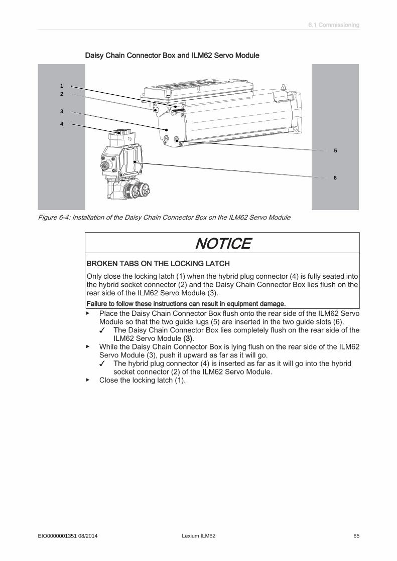
Daisy Chain Connector Box and ILM62 Servo Module
1
2
3
4
6
5
Figure 6-4: Installation of the Daisy Chain Connector Box on the ILM62 Servo Module
NOTICEBROKEN TABS ON THE LOCKING LATCHOnly close the locking latch (1) when the hybrid plug connector (4) is fully seated intothe hybrid socket connector (2) and the Daisy Chain Connector Box lies flush on therear side of the ILM62 Servo Module (3).Failure to follow these instructions can result in equipment damage.▶ Place the Daisy Chain Connector Box flush onto the rear side of the ILM62 Servo
Module so that the two guide lugs (5) are inserted in the two guide slots (6).The Daisy Chain Connector Box lies completely flush on the rear side of theILM62 Servo Module (3).
▶ While the Daisy Chain Connector Box is lying flush on the rear side of the ILM62Servo Module (3), push it upward as far as it will go.
The hybrid plug connector (4) is inserted as far as it will go into the hybridsocket connector (2) of the ILM62 Servo Module.
▶ Close the locking latch (1).
6.1 Commissioning
Schneider Electric 08/2014 Lexium ILM62 65EIO0000001351 08/2014
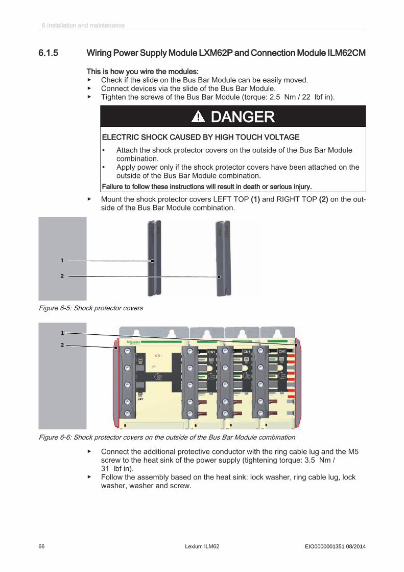
6.1.5 Wiring Power Supply Module LXM62P and Connection Module ILM62CM
This is how you wire the modules:▶ Check if the slide on the Bus Bar Module can be easily moved.▶ Connect devices via the slide of the Bus Bar Module.▶ Tighten the screws of the Bus Bar Module (torque: 2.5 Nm / 22 lbf in).
DANGERELECTRIC SHOCK CAUSED BY HIGH TOUCH VOLTAGE
• Attach the shock protector covers on the outside of the Bus Bar Modulecombination.
• Apply power only if the shock protector covers have been attached on theoutside of the Bus Bar Module combination.
Failure to follow these instructions will result in death or serious injury.
▶ Mount the shock protector covers LEFT TOP (1) and RIGHT TOP (2) on the out‐side of the Bus Bar Module combination.
1
2
Figure 6-5: Shock protector covers
1
2
Figure 6-6: Shock protector covers on the outside of the Bus Bar Module combination
▶ Connect the additional protective conductor with the ring cable lug and the M5screw to the heat sink of the power supply (tightening torque: 3.5 Nm /31 lbf in).
▶ Follow the assembly based on the heat sink: lock washer, ring cable lug, lockwasher, washer and screw.
6 Installation and maintenance
66 Lexium ILM62 Schneider Electric 08/2014EIO0000001351 08/2014

DANGERHAZARD OF ELECTRIC SHOCK CAUSED BY HIGH TOUCH VOLTAGE DUE TODEVICE LEAKAGE CURRENT HIGHER THAN 3.5 MA AC
• Connect the device via a fixed connection with the power supply network.• Additionally one of the following measures should be applied:
- Use a cross-section of the protective conductor of at least 10 mm2 (AWG 8)copper or 16 mm2 (AWG 6) aluminum.- Provide an automatic disconnection of the power supply in case of a disconti‐nuity of the protective conductor.- Provide an additional terminal for a second protective conductor of the samecross-sectional area as the original protective conductor.
Failure to follow these instructions will result in death or serious injury.▶ Check that terminals are secure and check necessary cable cross sectional areas
for correctness.▶ Check that the shielding works flawlessly, eliminate short circuits and interrup‐
tions.▶ Connect ground cable to the motor flange (1) and tighten it with a 2.8 Nm
(24.76 lbf in) torque.The motor is now grounded with the machine bed.
▶ Do not choose a connection cross-section of the earthing cable that is smallerthan the cross-section of the main connection.
▶ Or, connect the motor to the grounded machine bed immediately above the motorflange.
6.1 Commissioning
Schneider Electric 08/2014 Lexium ILM62 67EIO0000001351 08/2014

6.1.6 Wiring as of Connection Module ILM62CM in line structure or tree struc‐ture
The wiring of Connection Module ILM62CM, Distribution Box ILM62DB and ILM62Servo Module in line structure or tree structure occurs with hybrid cables.The hybrid cable variants suitable for line or tree structures are listed in the type codefigure "ILM 62 Accessories" (see 3.3.5 ILM62 accessories).The hybrid plug connector variants presented in the following are suitable for wiring inline or tree structures.
D1 D2D0
D1
D2D0
Figure 6-7: Plug connector designs of hybrid cables
D0 straight connectionD1 Connection at the bottom (Distribution Box ILM62DB) or on the left (ILM62 Servo Module)D2 Connection on the top (Distribution Box ILM62DB) or on the right (ILM62 Servo Module)
This is how you wire the modules:
▪ For an overview of the different connections, refer to the chapter Electrical Con‐nections (see 7.8 Electrical connections).
Depending on the selected identification mode in the Automation Toolkit SoMa‐chine Motion Logic Builder, an interchanged connection of the connections Sercos1/Sercos 2 can lead to a mechanical breakdown.
NOTICEINTERCHANGED CONNECTION OF THE SERCOS CABLESEnsure that the Sercos cables are connected to the Sercos connections CN4/CN5 of the Connection Module ILM62CM according to the connection diagramof the machine manufacturer. Failure to follow these instructions can result in equipment damage.
▶ Connect connections CN4, CN5, CN7 and CN8 (Sercos, DC bus voltage, 24V,Inverter Enable) at the Connection Module ILM62CM with the Distribution BoxILM62DB by means of the pre-assembled hybrid cable.
6 Installation and maintenance
68 Lexium ILM62 Schneider Electric 08/2014EIO0000001351 08/2014

Sercos 2
Sercos 1
0V_out
24V_out
IE_ref
IE_sig
DC-
DC+
PE
▶ Remove protective cover from hybrid cables.▶ Connect up to four ILM62 Servo Modules at the Distribution Box ILM62DB using
hybrid cables. Engage the respective mounting bracket at both connection sides.
▶ Provide unused hybrid connection sockets with strapping plugs.The strapping plugs are not included in the scope of delivery of ILM62 ServoModule and must be ordered separately (order number: VW3E6023).Strapping plugs close the Sercos loop, serve as protection against hazardousvoltage and ensure the IP65 degree of protection.
DC bus cable Connection Connection Mod‐ule ILM62CM
Topological address Distribution BoxILM62DB
CN2 CN3 CN4 CN5Sercos 1 (black)Sercos 2 (red)
CN4CN5
4 3 2 1
Sercos 1 (black)Sercos 2 (red)
CN5CN4
1 2 3 4
Table 6-1: The topological address for CN2, CN3, CN4 and CN5 (Distribution Box ILM62DB)depends of the assignment of Sercos 1/Sercos 2 to CN4/CN5 (Connection Module ILM62CM)
6.1 Commissioning
Schneider Electric 08/2014 Lexium ILM62 69EIO0000001351 08/2014

The following boundary conditions must be observed for the system layout:
• Maximum cable length of 20 m (65.2 ft) from Connection Module ILM62CM toDistribution Box ILM62DB.
• Maximum cable length of 10 m (32.8 ft) from Distribution Box ILM62DB to Distri‐bution Box ILM62DB.
• Maximum cable length of 10 m (32.8 ft) from Distribution Box ILM62DB to ILM62Servo Module.
• Sum of all cable lengths max. 200 m (656 ft).• Maximum distance of 50 m (164 ft) between 2 active Sercos slaves e.g. way back
in the Sercos loop from ILM62 Servo Module to Power Supply Module LXM62P•••• Connection Module ILM62CM and Distribution Box ILM62DB are no active Sercos
slaves.
Please contact your Schneider Electric contact person in order to create a detailedsystem layout for the respective available net topology.The following two examples illustrate the longest path between 2 active Sercos slavesfor which a maximum length of 50 m (164 ft) is permissible. This critical distance isrespectively marked in blue.In the following example of a net topology in line structure the longest path is betweenthe Power Supply Module LXM62P••• and the last ILM62 Servo Module.
20 m (65.6 ft)
10 m
(32.8 ft)
10 m (32.8 ft)
10 m
(32.8 ft)
max.: 40 m (131.2 ft)
Figure 6-8: Example longest path for net topology in line structur
In the following example of a net topology in tree-structure the longest path is betweentwo ILM62 Servo Modules and not between the Power Supply Module LXM62P••• andthe last ILM62 Servo Module.
6 Installation and maintenance
70 Lexium ILM62 Schneider Electric 08/2014EIO0000001351 08/2014
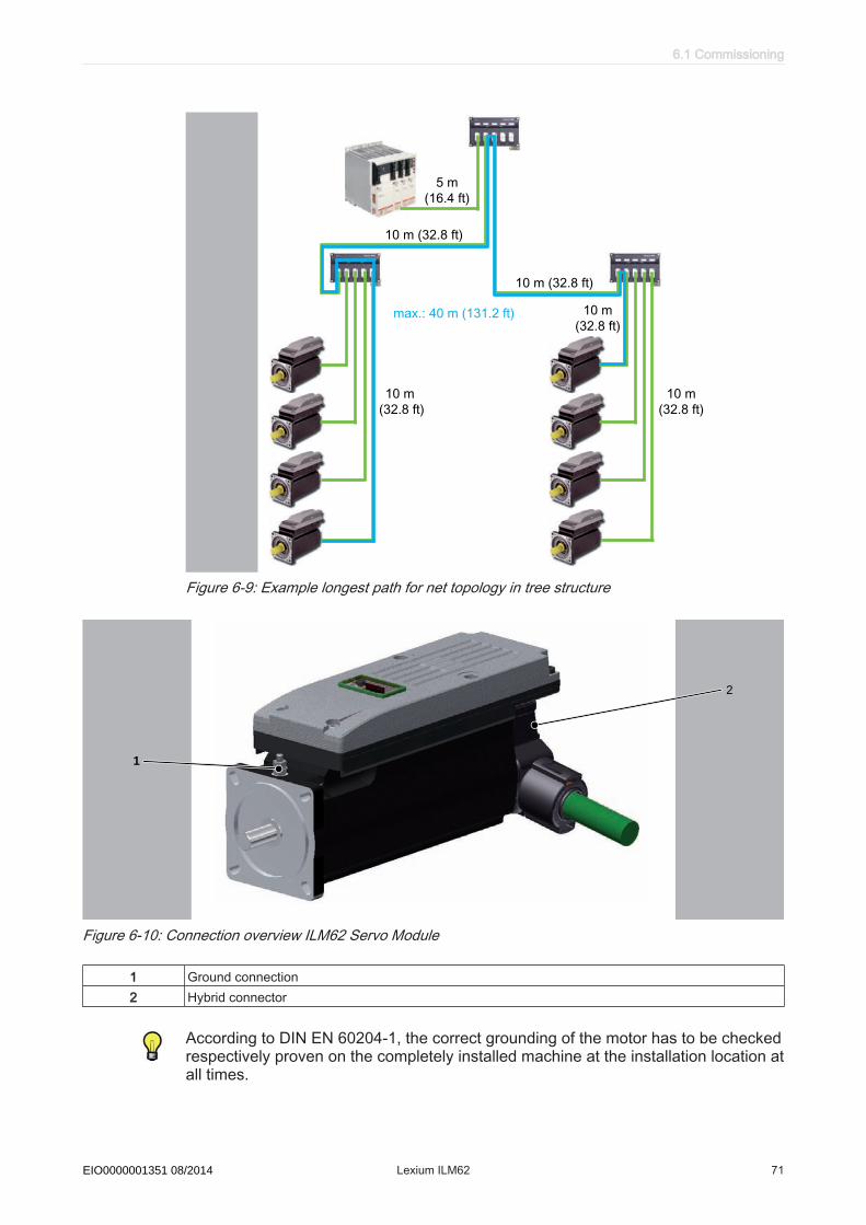
Figure 6-9: Example longest path for net topology in tree structure
TM
1
2
Figure 6-10: Connection overview ILM62 Servo Module
1 Ground connection2 Hybrid connector
According to DIN EN 60204-1, the correct grounding of the motor has to be checkedrespectively proven on the completely installed machine at the installation location atall times.
6.1 Commissioning
Schneider Electric 08/2014 Lexium ILM62 71EIO0000001351 08/2014
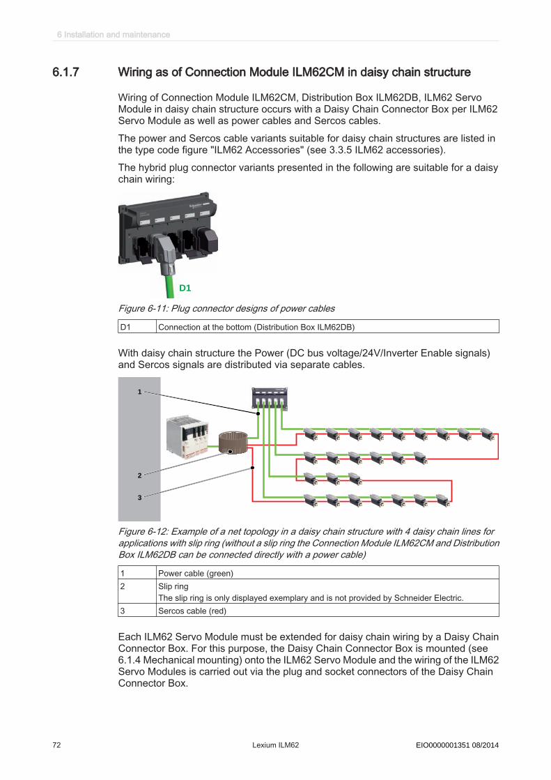
6.1.7 Wiring as of Connection Module ILM62CM in daisy chain structure
Wiring of Connection Module ILM62CM, Distribution Box ILM62DB, ILM62 ServoModule in daisy chain structure occurs with a Daisy Chain Connector Box per ILM62Servo Module as well as power cables and Sercos cables.The power and Sercos cable variants suitable for daisy chain structures are listed inthe type code figure "ILM62 Accessories" (see 3.3.5 ILM62 accessories).The hybrid plug connector variants presented in the following are suitable for a daisychain wiring:
D1
Figure 6-11: Plug connector designs of power cables
D1 Connection at the bottom (Distribution Box ILM62DB)
With daisy chain structure the Power (DC bus voltage/24V/Inverter Enable signals)and Sercos signals are distributed via separate cables.
1
2
3
Figure 6-12: Example of a net topology in a daisy chain structure with 4 daisy chain lines forapplications with slip ring (without a slip ring the Connection Module ILM62CM and DistributionBox ILM62DB can be connected directly with a power cable)
1 Power cable (green)2 Slip ring
The slip ring is only displayed exemplary and is not provided by Schneider Electric.3 Sercos cable (red)
Each ILM62 Servo Module must be extended for daisy chain wiring by a Daisy ChainConnector Box. For this purpose, the Daisy Chain Connector Box is mounted (see6.1.4 Mechanical mounting) onto the ILM62 Servo Module and the wiring of the ILM62Servo Modules is carried out via the plug and socket connectors of the Daisy ChainConnector Box.
6 Installation and maintenance
72 Lexium ILM62 Schneider Electric 08/2014EIO0000001351 08/2014
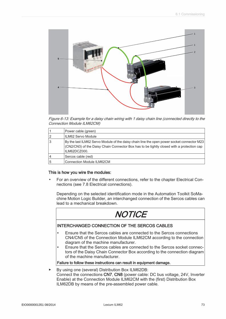
5
4
TM
2
3
1
1
Figure 6-13: Example for a daisy chain wiring with 1 daisy chain line (connected directly to theConnection Module ILM62CM)
1 Power cable (green)2 ILM62 Servo Module3 By the last ILM62 Servo Module of the daisy chain line the open power socket connector M23
(CN2/CN3) of the Daisy Chain Connector Box has to be tightly closed with a protection capILM62DCZ000.
4 Sercos cable (red)5 Connection Module ILM62CM
This is how you wire the modules:
▪ For an overview of the different connections, refer to the chapter Electrical Con‐nections (see 7.8 Electrical connections).
Depending on the selected identification mode in the Automation Toolkit SoMa‐chine Motion Logic Builder, an interchanged connection of the Sercos cables canlead to a mechanical breakdown.
NOTICEINTERCHANGED CONNECTION OF THE SERCOS CABLES
• Ensure that the Sercos cables are connected to the Sercos connectionsCN4/CN5 of the Connection Module ILM62CM according to the connectiondiagram of the machine manufacturer.
• Ensure that the Sercos cables are connected to the Sercos socket connec‐tors of the Daisy Chain Connector Box according to the connection diagramof the machine manufacturer.
Failure to follow these instructions can result in equipment damage.
▶ By using one (several) Distribution Box ILM62DB: Connect the connections CN7, CN8 (power cable: DC bus voltage, 24V, InverterEnable) at the Connection Module ILM62CM with the (first) Distribution BoxILM62DB by means of the pre-assembled power cable.
6.1 Commissioning
Schneider Electric 08/2014 Lexium ILM62 73EIO0000001351 08/2014

▶ Without Distribution Box ILM62DB: Connect the connections CN7, CN8 (power cable: DC bus voltage, 24V, InverterEnable) at the Connection Module ILM62CM with the first ILM62 Servo Module ofthe daisy chain line by means of the pre-assembled power cable.
▶ Connect up to 9 ILM62 Servo Modules per daisy chain line by means of powercables. Connect up to 4 daisy chain lines with a maximum of 9 ILM62 Servo Mod‐ules to a Distribution Box ILM62DB by means of power cables. Engage themounting bracket to the Distribution Box ILM62DB connection side.
▶ Connect the connections CN4, CN5 of the Connection Module ILM62CM with theSercos socket connectors of the Daisy Chain Connector Box to the ILM62 ServoModule by means of a pre-assembled Sercos cable.
▶ Connect the ILM62 Servo Modules to the Sercos socket connectors of the DaisyChain Connector Box by means of a pre-assembled Sercos cable.
▶ Tightly close the open power socket M23 (CN2/CN3) of the ILM62 Servo Modulewith a protection cap ILM62DCZ000 on every daisy chain line on the last DaisyChain Connector Box.
The following boundary conditions must be observed for the system layout:
• Maximum cable length of 20 m (65.2 ft) from Connection Module ILM62CM toDistribution Box ILM62DB.
• Maximum cable length of 10 m (32.8 ft) from Distribution Box ILM62DB to Distri‐bution Box ILM62DB.
• Maximum cable length of 10 m (32.8 ft) from Distribution Box ILM62DB or Con‐nection Module ILM62CM to the first ILM62 Servo Module of the daisy chain line.
• A maximum of 9 ILM62 Servo Modules can be connected per daisy chain line anda maximum cable length of 10 m (32.8 ft) between the first and the last ILM62Servo Module of the daisy chain line.
• Sum of all cable lengths max. 200 m (656 ft).• Maximum distance of 50 m (164 ft) between 2 active Sercos slaves.• Connection Module ILM62CM and Distribution Box ILM62DB are no active Sercos
slaves.
Please contact your Schneider Electric contact person in order to create a detailedsystem layout for the respective available net topology.
NOTICEINADMISSIBLE VOLTAGE / CURRENTOnly use net topologies approved by Schneider Electric.Failure to follow these instructions can result in equipment damage.
NOTICEINSUFFICIENT SEALEnsure that the protection cap ILM62DCZ000 is firmly secured to the open powersocket connector M23 (CN2/CN3) of the Daisy Chain Connector Box on the lastILM62 Servo Module.Failure to follow these instructions can result in equipment damage.
According to DIN EN 60204-1, the correct grounding of the motor has to be checkedrespectively proven on the completely installed machine at the installation location atall times.
6 Installation and maintenance
74 Lexium ILM62 Schneider Electric 08/2014EIO0000001351 08/2014
6.2 Maintenance, repair, cleaning▶ Observe the following instructions before carrying out maintenance on Device:How to de-energize the system:▶ Set main switch to "OFF Position".▶ Prevent main switch from being switched back on.▶ Wait 15 minutes after removing power (switching off) to allow the DC bus capac‐
itors to discharge.▶ Check whether the DC-BUS LED has turned off on all components located in the
axis group.
DANGERHAZARD OF ELECTRIC SHOCK, EXPLOSION, OR ARC FLASHBefore working on the device, check the DC bus with a measuring instrument to makesure that it is de-energized (< 42.4 Vdc).Failure to follow these instructions will result in death or serious injury.▶ Check DC+ to PE and DC- to PE with a suitable measuring instrument to make
sure it is de-energized before working on the device.
Help in case of an unforeseen issue:DC bus does not discharge completely.
▶ Do not repair or operate component.▶ Contact the Schneider Electric contact partner.
6.2 Maintenance, repair, cleaning
Schneider Electric 08/2014 Lexium ILM62 75EIO0000001351 08/2014
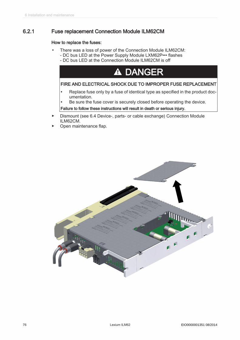
6.2.1 Fuse replacement Connection Module ILM62CM
How to replace the fuses:
▪ There was a loss of power of the Connection Module ILM62CM:- DC bus LED at the Power Supply Module LXM62P••• flashes- DC bus LED at the Connection Module ILM62CM is off
DANGERFIRE AND ELECTRICAL SHOCK DUE TO IMPROPER FUSE REPLACEMENT
• Replace fuse only by a fuse of identical type as specified in the product doc‐umentation.
• Be sure the fuse cover is securely closed before operating the device.Failure to follow these instructions will result in death or serious injury.
▶ Dismount (see 6.4 Device-, parts- or cable exchange) Connection ModuleILM62CM.
▶ Open maintenance flap.
6 Installation and maintenance
76 Lexium ILM62 Schneider Electric 08/2014EIO0000001351 08/2014

▶ On the back side of the housing remove both fuses from the holding device usinga screwdriver and replace them by new fuses (order number VW3E6024) of thesame type.
▶ Close maintenance flap and mount (see 6.1.4 Mechanical mounting) the Con‐nection Module ILM62CM.
▶ ILM62 Restart (see 6.1.5 Wiring Power Supply Module LXM62P and ConnectionModule ILM62CM) the system.If after the fuse replacement the Connection Module ILM62CM still is not readyfor operation or fails again after recommissioning, contact your Schneider Electricrepresentative.
6.2 Maintenance, repair, cleaning
Schneider Electric 08/2014 Lexium ILM62 77EIO0000001351 08/2014
6.2.2 Repair
In case of repair proceed as follows:▶ Contact the Schneider Electric Customer Service (see 9.1 Contact addresses).▶ Observe the following instructions for ESD protection in order to avoid any damage
due to electrostatic discharge:
NOTICEELECTROSTATIC DISCHARGE
• Do not touch any of the electrical connector contacts.• Prevent electrostatic charges, e.g., by wearing appropriate clothing and using
anti-static devices.• Remove existing static charge by touching a grounded, metallic surface.Failure to follow these instructions can result in equipment damage.
6.2.3 Cleaning
How to clean the ILM62 component:▶ De-energize ILM62 components.▶ Remove ILM62 components.▶ Use cleaning processes appropriate to the degree of protection of the ILM62
components.It is not possible to test in advance, all materials of the Schneider Electric product rangethat are used presently and in the future on the compatibility with the cleaning agentsavailable on the market. Care must be taken because some agents may have dele‐terious effects on plastics and stainless steel welds.
NOTICECORROSION CAUSED BY CLEANING AGENTS
• Before using a cleaning agent, carry out a compatibility test in relation to thecleaning agent and the component affected.
• Do not use alkaline detergent.• Do not use any chlorid-containing cleaning agents.• Do not use any sulphuric acid containing detergent.Failure to follow these instructions can result in equipment damage.
For more information on the material properties of your component (see 7.5 Mechan‐ical and electrical data).▶ Then blow out ILM62 components with dry pressurized air (max. 1bar /
14.5PSI).The standard cooling method of the motor is by natural convection. Therefore, keepthe motor surfaces free from dirt.
6 Installation and maintenance
78 Lexium ILM62 Schneider Electric 08/2014EIO0000001351 08/2014
6.3 Spare part inventory▶ Keep a stock of the most important components to make certain the equipment is
functioning and ready for operation at all times.
NOTICEINCREASED PULSE ENERGY ABSORPTION CAPACITY OF THE POWERSUPPLY MODULE LXM62P•••Only exchange Power Supply Module LXM62P••• with the same or greater revi‐sion status.Failure to follow these instructions can result in equipment damage.
▶ Only exchange devices with the same hardware configuration to ensure the com‐patibility.
▶ Indicate the following information on the spare part order:Item name: for example, ILM0701P01A0000Hardware code: for example, RS02Software version: e.g. SW: 00.24.21
This information can be found on the nameplate.
6.3 Spare part inventory
Schneider Electric 08/2014 Lexium ILM62 79EIO0000001351 08/2014
6.4 Device-, parts- or cable exchange
DANGERHAZARD OF ELECTRIC SHOCK, EXPLOSION, OR ARC FLASH
• Operate electrical components only with a connected protective conductor.• After the installation, verify the fixed connection of the protective conductor to all
electrical devices to ensure that connection complies with the connection dia‐gram.
• Before enabling the device, safely cover the live components to prevent contact.• Do not touch the electrical connection points of the components when the unit is
switched on.• Provide protection against indirect contact (EN 50178).• Disconnect/plug in Plug-in type connectors of the cables, plug-in terminals on the
device and Bus Bar Module only when the system is disconnected from the powersupply.
• Insulate the unused conductors on both ends of the motor cable because ACvoltages in the motor cable can couple to unused conductors.
Failure to follow these instructions will result in death or serious injury.
NOTICEIMPROPER REPLACEMENT OR OPENING OF THE DEVICE HOUSING
• Do not open the housing of the device for commissioning, replacement or anyother reason whatsoever.
• Observe and respect the instructions and specifications of the machine manu‐facturer when replacing the device.
• Replace defective devices as a whole.Failure to follow these instructions can result in equipment damage.
6 Installation and maintenance
80 Lexium ILM62 Schneider Electric 08/2014EIO0000001351 08/2014
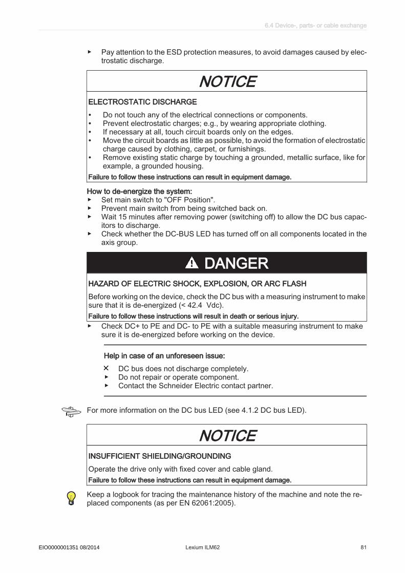
▶ Pay attention to the ESD protection measures, to avoid damages caused by elec‐trostatic discharge.
NOTICEELECTROSTATIC DISCHARGE
• Do not touch any of the electrical connections or components.• Prevent electrostatic charges; e.g., by wearing appropriate clothing.• If necessary at all, touch circuit boards only on the edges.• Move the circuit boards as little as possible, to avoid the formation of electrostatic
charge caused by clothing, carpet, or furnishings.• Remove existing static charge by touching a grounded, metallic surface, like for
example, a grounded housing.Failure to follow these instructions can result in equipment damage.
How to de-energize the system:▶ Set main switch to "OFF Position".▶ Prevent main switch from being switched back on.▶ Wait 15 minutes after removing power (switching off) to allow the DC bus capac‐
itors to discharge.▶ Check whether the DC-BUS LED has turned off on all components located in the
axis group.
DANGERHAZARD OF ELECTRIC SHOCK, EXPLOSION, OR ARC FLASHBefore working on the device, check the DC bus with a measuring instrument to makesure that it is de-energized (< 42.4 Vdc).Failure to follow these instructions will result in death or serious injury.▶ Check DC+ to PE and DC- to PE with a suitable measuring instrument to make
sure it is de-energized before working on the device.
Help in case of an unforeseen issue:DC bus does not discharge completely.
▶ Do not repair or operate component.▶ Contact the Schneider Electric contact partner.
For more information on the DC bus LED (see 4.1.2 DC bus LED).
NOTICEINSUFFICIENT SHIELDING/GROUNDINGOperate the drive only with fixed cover and cable gland.Failure to follow these instructions can result in equipment damage.
Keep a logbook for tracing the maintenance history of the machine and note the re‐placed components (as per EN 62061:2005).
6.4 Device-, parts- or cable exchange
Schneider Electric 08/2014 Lexium ILM62 81EIO0000001351 08/2014

6.4.1 Replacement of devices and cables of Connection Module ILM62CM
How to replace the ILM62 component:▶ Disconnect all connection cables on the device that shall be replaced.▶ Loosen the screwed connections on the wiring bus (CN1) of the component that
shall be replaced.▶ If present, loosen the screwed connections of the adjacent device on the right
hand side.▶ Push both slides (CN1) to the center of the device.
CAUTIONFALLING HEAVY LOADDo not fully remove the screw connections of the device mounting suspension orthe device could fall out/down.Failure to follow these instructions can result in injury or equipment damage.
▶ Loosen the screwed connections of the device mounting suspension on the topand bottom side.
▶ Remove the ILM62 component and exchange the complete unit.▶ Install the new ILM62 component and tighten the screwed connections on the top
and bottom side.
DANGERELECTRIC SHOCK CAUSED BY HIGH TOUCH VOLTAGE
• Attach the shock protector covers on the outside of the Bus Bar Modulecombination.
• Switch on the device only if the shock protector covers have been attachedon the outside of the Bus Bar Module combination.
Failure to follow these instructions will result in death or serious injury.
▶ Check if a shock protector cover is attached to the wiring bus (CN1) at the end ofan axis combination.
▶ Connect the ILM62 component according to the circuit diagram of the machine.
DANGERINCORRECT ASSIGNMENT OF NEW CABLESIf you are not using prefabricated cables, make sure that the assignment of thenew cables complies with the connection diagram of the machine manufacturer.Failure to follow this instruction will result in death or serious injury.
Depending on the selected identification mode in the Automation Toolkit SoMachineMotion Logic Builder, an interchanged connection of the connection Sercos 1/Sercos2 or the Sercos cables can lead to a mechanical breakdown.
6 Installation and maintenance
82 Lexium ILM62 Schneider Electric 08/2014EIO0000001351 08/2014

NOTICEINTERCHANGED CONNECTION OF SERCOS CABLESEnsure that the Sercos cables are connected to the Sercos connections CN4/CN5 ofthe Connection Module ILM62CM according to the connection diagram of the ma‐chine manufacturer.Failure to follow these instructions can result in equipment damage.▶ After replacing a ILM62 component, proceed as by the first commissioning.
For further information on this (see 6.1 Commissioning).
Keep a logbook for tracing the maintenance history of the machine and note the re‐placed components (as per EN 62061:2005).
6.4 Device-, parts- or cable exchange
Schneider Electric 08/2014 Lexium ILM62 83EIO0000001351 08/2014

6.4.2 Replacement of devices and cables of Distribution Box ILM62DB
How to replace the Distribution Box ILM62DB:▶ Pay attention to the ESD protection measures, to avoid damages caused by elec‐
trostatic discharge.
NOTICEELECTROSTATIC DISCHARGE
• Do not touch any of the electrical connections or components.• Prevent electrostatic charges; e.g., by wearing appropriate clothing.• If necessary at all, touch circuit boards only on the edges.• Move the circuit boards as little as possible, to avoid the formation of electrostatic
charge caused by clothing, carpet, or furnishings.• Remove existing static charge by touching a grounded, metallic surface, like for
example, a grounded housing.Failure to follow these instructions can result in equipment damage.
TM
CN5
CN4
CN3
CN2
CN1
▶ Unplug plug connector of the hybrid connector (cable connection to the Connec‐tion Module) at CN1. Before this, loosen the mounting brackets.
▶ Loosen plug connectors of the hybrid connectors of all connected motors (CN2 toCN5).
▶ Dismount earthing cable of shielding of the Distribution Box ILM62DB.▶ Replace Distribution Box ILM62DB as a whole.▶ Attach connectors of the hybrid connectors of all motors to be connected (CN2 to
CN5). Safeguard using mounting brackets.▶ Attach plug connector of the hybrid connector (cable connection of Connection
Module) at CN1 and lock mounting brackets.▶ Mount earthing cable at shielding of the Distribution Box ILM62DB.
6 Installation and maintenance
84 Lexium ILM62 Schneider Electric 08/2014EIO0000001351 08/2014

How to replace the cables:Cable installation▶ Wire earthing cable between Connection Module ILM62CM and Distribution Box
ILM62DB.▶ If available, pull off the strapping plug from contacts CN1 - CN5. Before this, loosen
the mounting brackets.▶ Remove protective cover at the hybrid connector.▶ Wire pre-assembled hybrid connector for the connection between Connection
Module ILM62CM and Distribution Box ILM62DB. Attach plug connector at X1connection of the Distribution Box ILM62DB. Perform connections CN4-5, CN6,CN7 and CN8 at the Connection Module ILM62CM according to the connectionoverview in Chapter (see 7.8.1 Connection Module ILM62CM).
▶ Attach hybrid connector at ILM62 Servo Module and connect to one of connec‐tions CN2-CN5. Lock both connections using mounting brackets.
Cable removal▶ Dismount earthing cable between Connection Module ILM62CM and Distribution
Box ILM62DB.▶ Loosen the mounting bracket (ILM62 Servo Module and Distribution Box
ILM62DB), pull off the hybrid connector or power cable (daisy chain wiring) at theILM62 Servo Module and loosen the plug connector of connections CN2-CN5.
▶ Close free connections of the Distribution Box ILM62DB with strapping plugs.▶ Equip the loosened hybrid cable with protective covers.Keep a logbook for tracing the maintenance history of the machine and note the re‐placed components (as per EN 62061:2005).
6.4 Device-, parts- or cable exchange
Schneider Electric 08/2014 Lexium ILM62 85EIO0000001351 08/2014

6.4.3 Replacement of devices and cables of ILM62 Servo Module
How to replace the ILM62 Servo Module:
CAUTIONELECTROSTATIC DISCHARGE
• Use the original or similar packaging to send back components.• Components must be packaged in ESD packaging/film.Failure to follow these instructions can result in damage to components and loss of warrantyclaim.
NOTICEIMPROPER REPLACEMENT OR OPENING OF THE ILM62 COMPONENTS
• Do not open the ILM62 component to put it into operation or replace it.• In addition to the following instructions, you must observe the machine manu‐
facturer's specifications when replacing of the ILM62 components.Failure to follow these instructions can result in equipment damage.▶ Take preliminary measures.▶ Put main switch in "OFF" position to free system of voltage.▶ Prevent main switch from being switched back on.
WARNINGUNINTENTIONAL AXIS MOVEMENTS DUE TO LOSS OF REFERENCES IN CASEOF A MOTOR REPLACEMENTFor servo axes with indirect distance measuring systems, restore the reference to themachine coordinate system via the motor encoder every time a motor is replaced.Failure to follow these instructions can result in death or serious injury.
NOTICEMECHANICAL FORCE TO THE ENCODER SYSTEM
• Prevent impacts on the motor shaft when removing and attaching couplings tothe motor shaft, as this could damage the encoder.
• Use appropriate tools, such as an extractor.• Avoid mechanical damage to the coating of the motor housing.Failure to follow these instructions can result in equipment damage.▶ Replace the drive according to the machine manufacturer's specifications.▶ Connect the earthing cable and tighten it with a 2.8 Nm torque.
6 Installation and maintenance
86 Lexium ILM62 Schneider Electric 08/2014EIO0000001351 08/2014
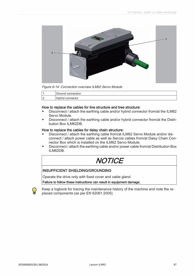
TM
1
2
Figure 6-14: Connection overview ILM62 Servo Module
1 Ground connection2 Hybrid connector
How to replace the cables for line structure and tree structure:▶ Disconnect / attach the earthing cable and/or hybrid connector from/at the ILM62
Servo Module.▶ Disconnect / attach the earthing cable and/or hybrid connector from/at the Distri‐
bution Box ILM62DB.How to replace the cables for daisy chain structure:▶ Disconnect / attach the earthing cable from/at ILM62 Servo Module and/or dis‐
connect / attach power cable as well as Sercos cables from/at Daisy Chain Con‐nector Box which is installed on the ILM62 Servo Module.
▶ Disconnect / attach the earthing cable and/or power cable from/at Distribution BoxILM62DB.
NOTICEINSUFFICIENT SHIELDING/GROUNDINGOperate the drive only with fixed cover and cable gland.Failure to follow these instructions can result in equipment damage.
Keep a logbook for tracing the maintenance history of the machine and note the re‐placed components (as per EN 62061:2005).
6.4 Device-, parts- or cable exchange
Schneider Electric 08/2014 Lexium ILM62 87EIO0000001351 08/2014

7 Technical data
7.1 Definition of technical data
Abbre‐viation
Unit Explanation
I0 [Arms] Standstill current Effective value of the motor current at standstill torque M0
IN [Arms] Rated current Effective value of the motor current at rated torque MN
Imax [Arms] Peak currentEffective value of the motor current at peak torque Mmax
JM [kgcm2] Rotor moment of inertia The rotor inertia refers to a motor without brake.
kT [Nm/Arms] Torque constant Quotient from the standstill torque M0 and standstill current I0 .
m [kg] Mass Motor mass without brake and without fan
M0 [Nm] Standstill torque; Continuous torque (100% ED) at 5 min-1 by an ambient temperature of 40 °C ..MN [Nm] Rated torque; Continuous torque (100% ED) by nN due to the speed-dependent losses less than
M0, by an ambient temperature of 40 °C ..Mmax [Nm] Peak torque
The maximum torque that the servo motor can briefly deliver to the output shaft.nN [min-1] Rated motor speednmax [min-1] Mechanical limit velocityPN [kW] Mechanical rated power (power delivered to the shaft)
At the rated motor speed and load with the rated torqueRU-V, 20 [Ω] Winding resistance
Resistance between two phases at a winding temperature of 20 °C.LU-V [mH] Winding inductance between two phaseskE [Vrms/kmin-1] Voltage constant; Induced voltage between two phases at 1000 min-1
V [m/s2] Maximum vibration (all directions)S [m/s2] Maximum shock (all directions)TTK [°C] Response limit temperature sensortth [min] Thermal time constantp Number of pole pairs
Table 7-1: Physical sizes with units and explanations
7 Technical data
88 Lexium ILM62 Schneider Electric 08/2014EIO0000001351 08/2014

7.2 Ambient conditions
Connection Module ILM62CMAmbient condi‐
tions
Procedure Parameter Value BasisOperation Class 3K3 IEC/EN 60721-3-3
Degree of protection housing IP 20 with plugged-in connectorsDegree of protection installa‐tion site
IP 54, if safety circuit with InverterEnable is used
Pollution degree 2Ambient temperature +5 °C...+55 °C / +41 °F...+131 °FCondensation NoIcing Noother liquid NoRelative humidity 5% ... 85%Class 3M4Vibration 10m/s2 Shock 100m/s2
Transport Class 2K3 IEC/EN 60721-3-2Ambient temperature -25 °C...+70 °C / -13 °F...+158 °FCondensation NoIcing Noother liquid NoRelative humidity 5% ... 95%Class 2M2Vibration 15m/s2 Shock 300m/s2
Long-term stor‐age intransport pack‐aging
Class 1K4 IEC/EN 60721-3-1Ambient temperature -25 °C...+55 °C / -13 °F...+131 °FCondensation NoIcing Noother liquid NoRelative humidity 5% ... 95%
Table 7-2: Ambient conditions Connection Module ILM62CM
7.2 Ambient conditions
Schneider Electric 08/2014 Lexium ILM62 89EIO0000001351 08/2014

Installation alti‐tude
The installation altitude is defined as height above sea level.
Installation altitude without power reduction <1000m (<3281ft. )Installation altitude while complying with all of the followingconditions:
• 55°C (131°F ) max. ambient temperature• Reduction of the continuous power by 1% per 100 m
(328 ft. ) above 1000 m (3281 ft. )
1000 ... 2000m (3281 ... 6562ft. )
Installation altitude above sea level when complying with all ofthe following conditions:
• 40°C max. ambient temperature• Reduction of the continuous power by 1% per 100 m
(328 ft. ) above 1000 m (3281 ft. )• Overvoltages of the supplying grid limited to an overvolt‐
age category III according to IEC 60664-1/IEC61800-5-1
2000 ... 3000m (6562 ... 9843ft. )
Installation lo‐cation and con‐
nection
For operation, the Power Supply Module LXM62P••• and the Connection ModuleILM62CM must be mounted in a closed control cabinet. The devices must only beoperated with fixed connections.
Pollution de‐gree and de‐
gree of protec‐tion
Pollution degree according toIEC61800-5-1
2
Degree of protection according toIEC61800-5-1
IP 20 (control cabinet), IP65 (field devi‐ces)
Degree of pro‐tection when
using the safetyfunction
Ensure that no conductive pollution can deposit in the product (pollution degree 2).Conductive pollutions can cause the safety function to be ineffective.
7 Technical data
90 Lexium ILM62 Schneider Electric 08/2014EIO0000001351 08/2014

Distribution Box ILM62DB
Procedure Parameter Value BasisOperation Class 3K3 IEC/EN 60721-3-3
Degree of protection housing IP 65 with plugged-in connectorsPollution degree 2Ambient temperature +5 °C...+55 °C / +41 °F...+131 °FCondensation NoIcing Noother liquid NoRelative humidity 5% ... 85%Class 3M7Vibration 30m/s2 Shock 250m/s2
Transport Class 2K3 IEC/EN 60721-3-2Ambient temperature -25 °C...+70 °C / -13 °F...+158 °FCondensation NoIcing Noother liquid NoRelative humidity 5% ... 95%Class 2M2Vibration 10m/s2 Shock 300m/s2
Long-term stor‐age intransport pack‐aging
Class 1K4 IEC/EN 60721-3-1Ambient temperature -25 °C...+55 °C / -13 °F...+131 °FCondensation NoIcing Noother liquid NoRelative humidity 5% ... 85%
Table 7-3: Ambient conditions Distribution Box ILM62DB
7.2 Ambient conditions
Schneider Electric 08/2014 Lexium ILM62 91EIO0000001351 08/2014

Daisy Chain Connector Box
Procedure Parameter Value BasisOperation Class 3K4 IEC/EN 60721-3-3
Degree of protection housing IP 65 with plugged-in connectorsPollution degree 2Ambient temperature -20 °C...+60 °C / -4 °F...+140 °FCondensation NoIcing Noother liquid NoRelative humidity 5% ... 95%Class 3M7Vibration 30 m/s2
Shock 250 m/s2
Transport Class 2K2 IEC/EN 60721-3-2Ambient temperature -25 °C...+70 °C / -13 °F...+158 °FCondensation NoIcing Noother liquid NoRelative humidity max. 75%Class 2M2Vibration 15 m/s2
Shock 300 m/s2
Long-term stor‐age intransport pack‐aging
Class 1K2 IEC/EN 60721-3-1Ambient temperature -25 °C...+55 °C / -13 °F...+131 °FCondensation NoIcing Noother liquid NoRelative humidity 5% ... 85%
Table 7-4: Ambient conditions Daisy Chain Connector Box
7 Technical data
92 Lexium ILM62 Schneider Electric 08/2014EIO0000001351 08/2014
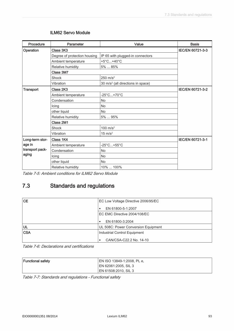
ILM62 Servo Module
Procedure Parameter Value BasisOperation Class 3K3 IEC/EN 60721-3-3
Degree of protection housing IP 65 with plugged-in connectorsAmbient temperature +5°C...+40°CRelative humidity 5% ... 85%Class 3M7Shock 250 m/s2
Vibration 30 m/s2 (all directions in space)Transport Class 2K3 IEC/EN 60721-3-2
Ambient temperature -25°C...+70°CCondensation NoIcing Noother liquid NoRelative humidity 5% ... 95%Class 2M1Shock 100 m/s2
Vibration 15 m/s2
Long-term stor‐age intransport pack‐aging
Class 1K4 IEC/EN 60721-3-1Ambient temperature -25°C...+55°CCondensation NoIcing Noother liquid NoRelative humidity 10% ... 100%
Table 7-5: Ambient conditions for ILM62 Servo Module
7.3 Standards and regulations
CE EC Low Voltage Directive 2006/95/EC
• EN 61800-5-1:2007EC EMC Directive 2004/108/EC
• EN 61800-3:2004UL UL 508C: Power Conversion EquipmentCSA Industrial Control Equipment
• CAN/CSA-C22.2 No. 14-10
Table 7-6: Declarations and certifications
Functional safety EN ISO 13849-1:2008, PL e,EN 62061:2005, SIL 3EN 61508:2010, SIL 3
Table 7-7: Standards and regulations - Functional safety
7.3 Standards and regulations
Schneider Electric 08/2014 Lexium ILM62 93EIO0000001351 08/2014
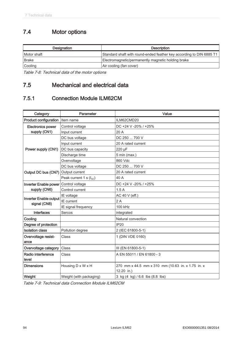
7.4 Motor options
Designation DescriptionMotor shaft Standard shaft with round-ended feather key according to DIN 6885 T1Brake Electromagnetic/permanently magnetic holding brakeCooling Air cooling (fan cover)
Table 7-8: Technical data of the motor options
7.5 Mechanical and electrical data
7.5.1 Connection Module ILM62CM
Category Parameter ValueProduct configuration Item name ILM62CMD20
Electronics powersupply (CN1)
Control voltage DC +24 V -20% / +25%Input current 20 A
Power supply (CN1)
DC bus voltage DC 250 ... 700 VInput current 20 A rated currentDC bus capacity 220 µFDischarge time 5 min (max.)Overvoltage 860 Vdc
Output DC bus (CN7)DC bus voltage DC 250 ... 700 VOutput current 20 A rated currentPeak current 1 s (ISC) 40 A
Inverter Enable powersupply (CN6)
Control voltage DC +24 V -20% / +25%Control current 1.5 A
Inverter Enable outputsignal (CN8)
IE voltage AC 40 V (eff.)IE current 2 AIE signal frequency 100 kHz
Interfaces Sercos integratedCooling Natural convectionDegree of protection IP20Isolation class Pollution degree 2 (IEC 61800-5-1)Overvoltage resist‐ance
Class 1 (DIN VDE 0160)
Overvoltage category Class III (EN 61800-5-1)Radio interferencelevel
Class A EN 55011 / EN 61800 - 3
Dimensions Housing D x W x H 270 mm x 44.5 mm x 310 mm (10.63 in. x 1.75 in. x12.20 in.)
Weight Weight (with packaging) 3 kg (4 kg) / 6.6 lbs (8.8 lbs)
Table 7-9: Technical data Connection Module ILM62CM
7 Technical data
94 Lexium ILM62 Schneider Electric 08/2014EIO0000001351 08/2014

7.5.2 Distribution Box ILM62DB
Category Parameter ValueProduct configuration Item name Distribution Box ILM62DBDC power supply(CN1 - CN5)
DC bus voltage DC 250 V ... 700 VRated current 20 ADC capacity 100 µF
Electronics powersupply(CN1 - CN5)
Control voltage / -current DC 24 V (-20%..+25%) / max 20 AControl voltage capacity 1000 µF
Inverter Enable(CN1 - CN5)
IE voltage AC 42 V (eff.)IE current 2 A (eff.)IE signal frequency 100 kHz
Ethernet Sercos(CN1 - CN5)
Data rate 100 Mbit/s
Cooling Natural convectionDegree of protection IP 65Isolation class Pollution degree 2 (IEC 61800-5-1:2007)Overvoltage category Class III (IEC 61800-5-1:2007), T2 (DIN VDE 0110)Overvoltage resist‐ance
Class 1 (DIN VDE 0160)
Radio interferencelevel
Class A EN 55011 / EN 61800 - 3
Material Polycarbonate [Lexan 940A]Dimensions Housing D x W x H 151.4 mm x 230 mm x 94 mm (5.96 in. x 9.05 in. x 3.70 in.)Weight 0.85 kg (1.8 lbs)
Table 7-10: Technical data Distribution Box ILM62DB
7.5 Mechanical and electrical data
Schneider Electric 08/2014 Lexium ILM62 95EIO0000001351 08/2014

7.5.3 Daisy Chain Connector Box
Category Parameter ValueProduct configuration Item name Daisy Chain Connector BoxDC power supply(CN1, CN2/CN3)
DC bus voltage DC 250 V ... 700 VRated current 20 A
Electronics power sup‐ply(CN1, CN2/CN3)
Control voltage / -current DC 24 V (-20%..+25%) / max 20 A
Inverter Enable(CN1, CN2/CN3)
IE voltage AC 42 V (eff.)IE current 2 A (eff.)IE signal frequency 100 kHz
Ethernet Sercos(CN4/CN5)
Data rate 100 Mbit/s
Cooling Natural convectionDegree of protection IP 65Isolation class Pollution degree 2 (IEC 61800-5-1:2007)Overvoltage category Class III (IEC 61800-5-1:2007), T2 (DIN VDE 0110)Overvoltage resistance Class 1 (DIN VDE 0160)Radio interference level Class A EN 55011 / EN 61800 - 3Material Polybutylene terephthalate with 30% fiberglass [Pocan B 4235]DimensionsILM62DCA000 Type AILM62DCB000 Type BILM62DCC000 Type C
Housing D x W x H 74.6 mm x 73.3 mm x 93 mm (2.94 in. x 2.89 in. x 3.66 in.)Housing D x W x H 56.5 mm x 106.8 mm x 113.2 mm (2.22 in. x 4.20 in. x 4.46 in.)Housing D x W x H 56.5 mm x 106.8 mm x 140.2 mm (2.22 in. x 4.20 in. x 5.52 in.)
Weight Weight with packaging 0.86 kg (1.90 lbs)
Table 7-11: Technical data Daisy Chain Connector Box
7 Technical data
96 Lexium ILM62 Schneider Electric 08/2014EIO0000001351 08/2014
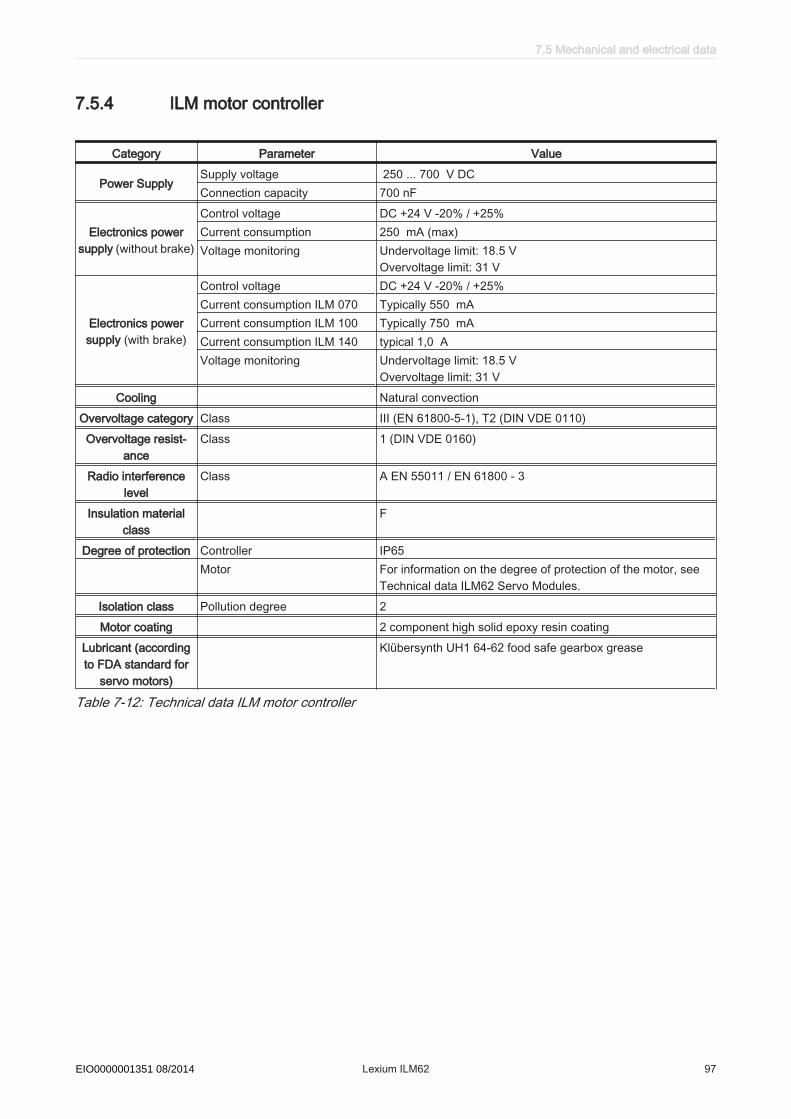
7.5.4 ILM motor controller
Category Parameter Value
Power SupplySupply voltage 250 ... 700 V DC Connection capacity 700 nF
Electronics powersupply (without brake)
Control voltage DC +24 V -20% / +25%Current consumption 250 mA (max)Voltage monitoring Undervoltage limit: 18.5 V
Overvoltage limit: 31 V
Electronics powersupply (with brake)
Control voltage DC +24 V -20% / +25%Current consumption ILM 070 Typically 550 mA Current consumption ILM 100 Typically 750 mA Current consumption ILM 140 typical 1,0 AVoltage monitoring Undervoltage limit: 18.5 V
Overvoltage limit: 31 VCooling Natural convection
Overvoltage category Class III (EN 61800-5-1), T2 (DIN VDE 0110)Overvoltage resist‐
anceClass 1 (DIN VDE 0160)
Radio interferencelevel
Class A EN 55011 / EN 61800 - 3
Insulation materialclass
F
Degree of protection Controller IP65Motor For information on the degree of protection of the motor, see
Technical data ILM62 Servo Modules.Isolation class Pollution degree 2Motor coating 2 component high solid epoxy resin coating
Lubricant (accordingto FDA standard for
servo motors)
Klübersynth UH1 64-62 food safe gearbox grease
Table 7-12: Technical data ILM motor controller
7.5 Mechanical and electrical data
Schneider Electric 08/2014 Lexium ILM62 97EIO0000001351 08/2014
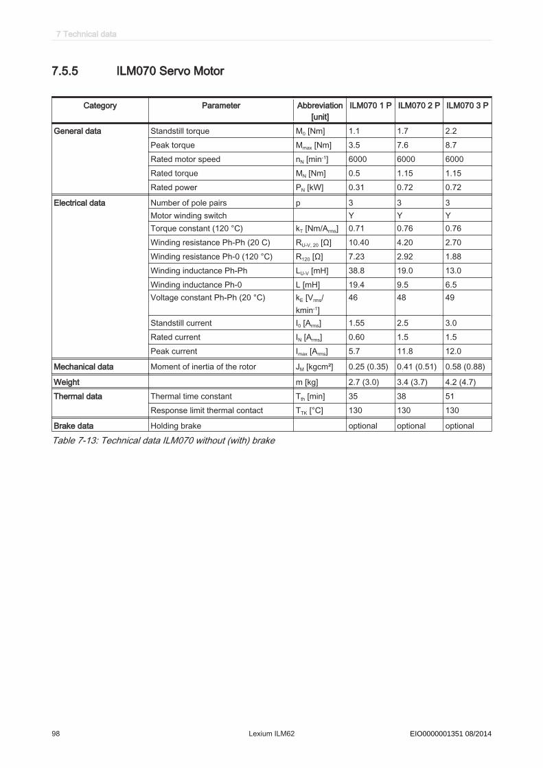
7.5.5 ILM070 Servo Motor
Category Parameter Abbreviation[unit]
ILM070 1 P ILM070 2 P ILM070 3 P
General data Standstill torque M0 [Nm] 1.1 1.7 2.2Peak torque Mmax [Nm] 3.5 7.6 8.7Rated motor speed nN [min-1] 6000 6000 6000Rated torque MN [Nm] 0.5 1.15 1.15Rated power PN [kW] 0.31 0.72 0.72
Electrical data Number of pole pairs p 3 3 3Motor winding switch Y Y YTorque constant (120 °C) kT [Nm/Arms] 0.71 0.76 0.76Winding resistance Ph-Ph (20 C) RU-V, 20 [Ω] 10.40 4.20 2.70Winding resistance Ph-0 (120 °C) R120 [Ω] 7.23 2.92 1.88Winding inductance Ph-Ph LU-V [mH] 38.8 19.0 13.0Winding inductance Ph-0 L [mH] 19.4 9.5 6.5Voltage constant Ph-Ph (20 °C) kE [Vrms/
kmin-1]46 48 49
Standstill current I0 [Arms] 1.55 2.5 3.0Rated current IN [Arms] 0.60 1.5 1.5Peak current Imax [Arms] 5.7 11.8 12.0
Mechanical data Moment of inertia of the rotor JM [kgcm²] 0.25 (0.35) 0.41 (0.51) 0.58 (0.88)
Weight m [kg] 2.7 (3.0) 3.4 (3.7) 4.2 (4.7)Thermal data Thermal time constant Tth [min] 35 38 51
Response limit thermal contact TTK [°C] 130 130 130
Brake data Holding brake optional optional optional
Table 7-13: Technical data ILM070 without (with) brake
7 Technical data
98 Lexium ILM62 Schneider Electric 08/2014EIO0000001351 08/2014
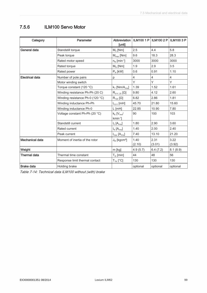
7.5.6 ILM100 Servo Motor
Category Parameter Abbreviation[unit]
ILM100 1 P ILM100 2 P ILM100 3 P
General data Standstill torque M0 [Nm] 2.5 4.4 5.8Peak torque Mmax [Nm] 9.6 18.3 28.3Rated motor speed nN [min-1] 3000 3000 3000Rated torque MN [Nm] 1.9 2.9 3.5Rated power PN [kW] 0.6 0.91 1.10
Electrical data Number of pole pairs p 4 4 4Motor winding switch Y Y YTorque constant (120 °C) kT [Nm/Arms] 1.39 1.52 1.61Winding resistance Ph-Ph (20 C) RU-V, 20 [Ω] 9.80 4.12 2.60Winding resistance Ph-0 (120 °C) R120 [Ω] 6.82 2.86 1.81Winding inductance Ph-Ph LU-V [mH] 45.70 21.80 15.60Winding inductance Ph-0 L [mH] 22.85 10.90 7.80Voltage constant Ph-Ph (20 °C) kE [Vrms/
kmin-1]90 100 103
Standstill current I0 [Arms] 1.80 2.90 3.60Rated current IN [Arms] 1.40 2.00 2.40Peak current Imax [Arms] 7.40 13.10 21.20
Mechanical data Moment of inertia of the rotor JM [kgcm²] 1.40(2.10)
2.31(3.01)
3.22 (3.92)
Weight m [kg] 4.9 (5.7) 6.4 (7.2) 8.1 (8.9)Thermal data Thermal time constant Tth [min] 44 48 56
Response limit thermal contact TTK [°C] 130 130 130
Brake data Holding brake optional optional optional
Table 7-14: Technical data ILM100 without (with) brake
7.5 Mechanical and electrical data
Schneider Electric 08/2014 Lexium ILM62 99EIO0000001351 08/2014

7.5.7 ILM140 Servo Motor
Category Parameter Abbreviation[unit]
ILM140 1 P ILM140 1 M ILM140 2 P
General data Standstill torque M0 [Nm] 7.5 8.5 12.5Peak torque Mmax [Nm] 27.0 27.0 55.0Rated motor speed nN [min-1] 3000 1500 2000Rated torque MN [Nm] 4.6 8.3 9.1Rated power PN [kW] 1.45 1.30 1.91
Electrical data Number of pole pairs p 5 5 5Motor winding switch Y Y YTorque constant (120 °C) kT [Nm/Arms] 1.60 2.65 2.60Winding resistance Ph-Ph (20 C) RU-V, 20 [Ω] 1.81 4.58 1.90Winding resistance Ph-0 (120 °C) R120 [Ω] 1.26 3.18 1.32Winding inductance Ph-Ph LU-V [mH] 19.10 50.0 22.0Winding inductance Ph-0 L [mH] 9.55 25.0 11.0Voltage constant Ph-Ph (20 °C) kE [Vrms/
kmin-1]108 175 173
Standstill current I0 [Arms] 4.70 3.20 4.8Rated current IN [Arms] 2.90 3.15 3.7Peak current Imax [Arms] 18.8 14.6 24.0
Mechanical data Moment of inertia of the rotor JM [kgcm²] 7.41 7.41 12.68
Weight (with brake) m [kg] 12.5 (13.8) 12.5 (13.8) 17.2 (18.5)Thermal data Thermal time constant Tth [min] 64 64 74
Response limit thermal contact TTK [°C] 130 130 130
Brake data Holding brake optional optional optional
Table 7-15: Technical data ILM140 without (with) brake
7 Technical data
100 Lexium ILM62 Schneider Electric 08/2014EIO0000001351 08/2014
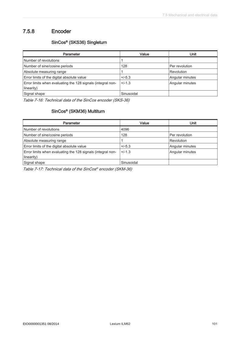
7.5.8 Encoder
SinCos® (SKS36) Singleturn
Parameter Value UnitNumber of revolutions 1Number of sine/cosine periods 128 Per revolutionAbsolute measuring range 1 RevolutionError limits of the digital absolute value +/-5.3 Angular minutesError limits when evaluating the 128 signals (integral non-linearity)
+/-1.3 Angular minutes
Signal shape Sinusoidal
Table 7-16: Technical data of the SinCos encoder (SKS-36)
SinCos® (SKM36) Multiturn
Parameter Value UnitNumber of revolutions 4096Number of sine/cosine periods 128 Per revolutionAbsolute measuring range 1 RevolutionError limits of the digital absolute value +/-5.3 Angular minutesError limits when evaluating the 128 signals (integral non-linearity)
+/-1.3 Angular minutes
Signal shape Sinusoidal
Table 7-17: Technical data of the SinCos® encoder (SKM-36)
7.5 Mechanical and electrical data
Schneider Electric 08/2014 Lexium ILM62 101EIO0000001351 08/2014

7.5.9 Motor shaft and bearings
Design of the shaft endSmooth
shaft end(standard)
With a non-positive connection, torque transmission must be achieved only by surfacepressure. That ensures safe power transmission without backlash.
Shaft end withround-ended
feather key ac‐cording to DIN
6885
Shaft connections with feather keys are positive. The feather key seating can deflectunder continuous strain with changing torques and prolonged reverse operation, caus‐ing backlash. As a result, rotational quality is reduced due to backlash. Increasingdeformation can lead to the feather key breaking and damage to the shaft. This typeof shaft hub connection is only suitable for low requirements. Therefore, we recom‐mend using smooth shaft ends.BearingThe back side bearing is designed as a fixed bearing and the bearing on shaft outputside as a floating bearing.Permissible shaft loadIn case of technical correct use, the life of drives is limited by the bearing life. Thecustomer may not replace the bearing, as the measuring systems integrated in thedrive must then be reinitialized.
Figure 7-1: Definition of shaft load
Motor 1000 min-1 2000 min-1 3000 min-1 4000 min-1 5000 min-1 6000 min-1
ILM070 1 P 660 520 460 410 380 360ILM070 2 P 710 560 490 450 410 390ILM070 3 P 730 580 510 460 430 400ILM100 1 P 900 720 630 - - -ILM100 2 P 990 790 690 - - -ILM100 3 P 1050 830 730 - - -ILM140 1 M 2210 1760 - - - -ILM140 1 P 2210 1760 1530 - - -ILM140 2 P 2430 1930 - - - -
Table 7-18: Permissible radial force Fradial [N]
7 Technical data
102 Lexium ILM62 Schneider Electric 08/2014EIO0000001351 08/2014

Basis for calculation:The permissible axial force Faxial [N] is calculated according to:
Faxial = 0.2 x Fradial
• Nominal bearing life L10h = 20,000 h for a shaft without feather key nut (for operatinghours at a 10% failure probability)
• Ambient temperature = 40 °C (approx. 100 °C storage temperature)• Peak torque = 10 % ED• Nominal torque = 100 % ED
7.5.10 Holding brake (optional)
To hold the axes without play during standstill or when the system is deactivated, youcan order the servo motors with a holding brake. The permanent magnetic brake is acontinuous surface unit with which the force of the permanent magnetic field is usedfor generating the braking effect (system opens electromagnetically).
Operating prin‐ciple of the
holding brake
The permanent magnetic field is compensated by an electromagnetic field for cancel‐ling the braking effect. Reliable release without detent torque that is independent ofthe mounting position is ensured by a steel spring. In addition to frictionless axial ar‐mature movement, it also offers the transmission of braking torque without backlash.The motors are provided with a varistor for reducing overvoltage when the brake isengaged.
CAUTIONPREMATURE WEAR OF THE HOLDING BRAKEUse the holding brake only when the axis is at a standstill or in emergency stop sit‐uations.Failure to follow these instructions can result in injury or equipment damage.
The times mentioned in the following apply when switching in the direct current circuit,when the motor is warm, and at the rated voltage. The disconnection time is the periodfrom switching on the current to the dying out of the torque to 10% of the rated torqueof the brake. The coupling time counts as the period from when the current is switchedoff to the attainment of the rated torque.
7.5 Mechanical and electrical data
Schneider Electric 08/2014 Lexium ILM62 103EIO0000001351 08/2014
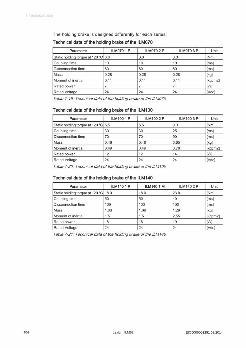
The holding brake is designed differently for each series:Technical data of the holding brake of the ILM070
Parameter ILM070 1 P ILM070 2 P ILM070 3 P UnitStatic holding torque at 120 °C 3.0 3.0 3.0 [Nm]Coupling time 10 10 10 [ms]Disconnection time 80 80 80 [ms]Mass 0.28 0.28 0.28 [kg]Moment of inertia 0.11 0.11 0.11 [kgcm2]Rated power 7 7 7 [W]Rated Voltage 24 24 24 [Vdc]
Table 7-19: Technical data of the holding brake of the ILM070
Technical data of the holding brake of the ILM100
Parameter ILM100 1 P ILM100 2 P ILM100 3 P UnitStatic holding torque at 120 °C 5.5 5.5 9.0 [Nm]Coupling time 30 30 25 [ms]Disconnection time 70 70 90 [ms]Mass 0.46 0.46 0.65 [kg]Moment of inertia 0.49 0.49 0.78 [kgcm2]Rated power 12 12 14 [W]Rated Voltage 24 24 24 [Vdc]
Table 7-20: Technical data of the holding brake of the ILM100
Technical data of the holding brake of the ILM140
Parameter ILM140 1 P ILM140 1 M ILM140 2 P UnitStatic holding torque at 120 °C 18.0 18.0 23.0 [Nm]Coupling time 50 50 40 [ms]Disconnection time 100 100 100 [ms]Mass 1.06 1.06 1.29 [kg]Moment of inertia 1.5 1.5 2.55 [kgcm2]Rated power 18 18 19 [W]Rated Voltage 24 24 24 [Vdc]
Table 7-21: Technical data of the holding brake of the ILM140
7 Technical data
104 Lexium ILM62 Schneider Electric 08/2014EIO0000001351 08/2014

7.6 Mounting arrangement and degree of protection
The drive degree of protection depends on the mounting arrangement. The mountingflange for all drive types is designed in such a way that the installation type is possibleaccording to the types of construction IM B5, IM V1 and IM V3 (mounting flange withthrough hole). By the DIN IEC 34-7 the drives can be mounted to the machine ac‐cording to the following listing types.:
Figure 7-2: Drive installations
NOTICEIMPERMISSIBLE MOUNTING POSITION AND PENETRATING LIQUIDSPrevent liquids from remaining on the motor shaft over an extended period of timewhen mounting the motor in the mounting position IM V3.Failure to follow these instructions can result in equipment damage.
It also cannot be ruled out that liquids penetrate the motor housing along the motorshaft even if a shaft sealing ring has been installed.
Motor part Degree of protection (ac‐cording to EN 60529)
Mounting position (conforming to DIN 42 950)
Shaft IP 50 IM V3IP 54 IM B5, IM V1IP 65 IM V3 (shaft sealing ring)
Surface/connections IP 65 IM B5, IM V1, IM V3
Table 7-22: Degree of protection of the ILM servo motor
7.7 Torque/speed characteristic curves
The torque-speed characteristic curve represents the following characteristics:
• The permissible permanent torque (operating type S 1)• The peak torque with mains voltage = 3 x 230 Vac
• The peak torque with mains voltage = 3 x 400 VacVac
• The peak torque with mains voltage = 3 x 480 Vac *(* for ILM140•• only)
7.6 Mounting arrangement and degree of protection
Schneider Electric 08/2014 Lexium ILM62 105EIO0000001351 08/2014

Md
Mmax 230V 3AC Mmax 400V 3AC Mmax 480V 3AC*
0,0
10,0
20,0
30,0
40,0
50,0
60,0
0 250 500 750 1000 1250 1500 1750 2000
n [min-1]
M [
Nm
]
Figure 7-3: Example of a torque-speed characteristic curve (* for ILM140•• only)
The characteristic curves refer to an ambient temperature of 40°C and a maximumwinding temperature of 120°C.
Figure 7-4: Torque-speed characteristic curve ILM 070 1 P
7 Technical data
106 Lexium ILM62 Schneider Electric 08/2014EIO0000001351 08/2014

Figure 7-5: Torque-speed characteristic curve ILM 070 2 P
Figure 7-6: Torque-speed characteristic curve ILM 070 3 P
7.7 Torque/speed characteristic curves
Schneider Electric 08/2014 Lexium ILM62 107EIO0000001351 08/2014

Figure 7-7: Torque-speed characteristic curve ILM 100 1 P
Figure 7-8: Torque-speed characteristic curve ILM 100 2 P
7 Technical data
108 Lexium ILM62 Schneider Electric 08/2014EIO0000001351 08/2014
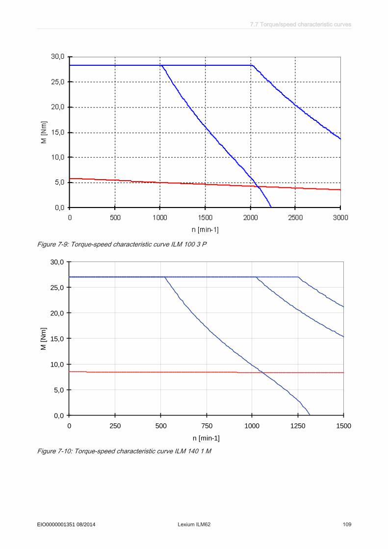
Figure 7-9: Torque-speed characteristic curve ILM 100 3 P
0,0
5,0
10,0
15,0
20,0
25,0
30,0
0 250 500 750 1000 1250 1500
n [min-1]
M [
Nm
]
Figure 7-10: Torque-speed characteristic curve ILM 140 1 M
7.7 Torque/speed characteristic curves
Schneider Electric 08/2014 Lexium ILM62 109EIO0000001351 08/2014

0,0
5,0
10,0
15,0
20,0
25,0
30,0
0 500 1000 1500 2000 2500 3000
n [min-1]
M [
Nm
]
Figure 7-11: Torque-speed characteristic curve ILM 140 1 P
0,0
10,0
20,0
30,0
40,0
50,0
60,0
0 250 500 750 1000 1250 1500 1750 2000
n [min-1]
M [
Nm
]
Figure 7-12: Torque-speed characteristic curve ILM 140 2 P
7 Technical data
110 Lexium ILM62 Schneider Electric 08/2014EIO0000001351 08/2014

7.8 Electrical connections
7.8.1 Connection Module ILM62CM
TM
CN3
CN2
CN1
CN4
CN6
CN5
CN7
CN8
Figure 7-13: Connection overview Connection Module ILM62CM
Connection Meaning Connection cross-section [mm2]/ [AWG] Tightening torque [Nm] / [lbf in]CN1 Bus Bar Module - / - 2.5 / 22.14
CN2/CN3 Sercos communication - / - - / -CN4 Sercos communication - / - - / -CN5 Sercos communication - / - - / -CN6 Inverter Enable 24 V 0.5 … 16 / 20 ... 6 - / -CN7 DC bus output 0.2 ... 6 / 24 ... 10 - / -CN8 Inverter Enable signal output /
24 V output0.2 ... 6 / 24 ... 10 - / -
Protective conductor 10 (cable lug) / 6 3.5 / 30.98
7.8 Electrical connections
Schneider Electric 08/2014 Lexium ILM62 111EIO0000001351 08/2014

CN1 - Bus Bar ModuleThe DC bus voltage and the 24Vdc control voltage will be distributed and the protectiveconductor connected via the Bus Bar Module. A separate cabling is not required.
Pin Designation Meaning1 Protective ground conductor
2 DC- - DC bus voltage3 DC + Dc bus voltage +4 24V Supply voltage +5 0V Supply voltage -
Table 7-23: Electrical connection - Bus Bar Module
CN2/CN3 - SercosThe Sercos connection is used for communication between the LMC controller, thepower supply and the Connection Module or modules.
Pin Designation Meaning1.1 Eth0_Tx+ Positive transmission signal1.2 Eth0_Tx- Negative transmission signal1.3 Eth0_Rx+ Positive receiver signal1.4 n.c. -1.5 n.c. -1.6 Eth0_Rx- Negative receiver signal1.7 n.c. -1.8 n.c. -2.1 Eth1_Tx+ Positive transmission signal2.2 Eth1_Tx- Negative transmission signal2.3 Eth1_Rx+ Positive receiver signal2.4 n.c. -2.5 n.c. -2.6 Eth1_Rx- Negative receiver signal2.7 n.c. -2.8 n.c. -
Table 7-24: Electrical connection - Sercos
7 Technical data
112 Lexium ILM62 Schneider Electric 08/2014EIO0000001351 08/2014

CN4 - SercosThe Sercos connection is used for communication between Connection ModuleILM62CM and ILM62 Servo Module.
Pin Designation Meaning1 Eth0_Tx+ Positive transmission signal2 Eth0_Tx- Negative transmission signal3 Eth0_Rx+ Positive receiver signal4 n.c. -5 n.c. -6 Eth0_Rx- Negative receiver signal7 n.c. -8 n.c. -
Table 7-25: Electrical connection - Sercos
CN5 - SercosThe Sercos connection is used for communication between Connection ModuleILM62CM and ILM62 Servo Module.
Pin Designation Meaning1 Eth0_Tx+ Positive transmission signal2 Eth0_Tx- Negative transmission signal3 Eth0_Rx+ Positive receiver signal4 n.c. -5 n.c. -6 Eth0_Rx- Negative receiver signal7 n.c. -8 n.c. -
Table 7-26: Electrical connection - Sercos
CN6 - Inverter Enable power supply 24VThe Inverter Enable voltage connection supplies the Inverter Enable output.
Pin Designation Meaning1 IE_p1 Supply voltage 24V for IE2 IE_p2 Supply voltage 24V for IE3 IE_n1 Supply voltage 0V for IE4 IE_n2 Supply voltage 0V for IE5 0V_int1 Control voltage 0V6 0V_int2 Control voltage 0V
Table 7-27: Inverter Enable supply voltage 24V
7.8 Electrical connections
Schneider Electric 08/2014 Lexium ILM62 113EIO0000001351 08/2014
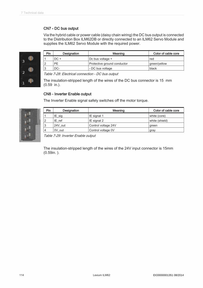
CN7 - DC bus outputVia the hybrid cable or power cable (daisy chain wiring) the DC bus output is connectedto the Distribution Box ILM62DB or directly connected to an ILM62 Servo Module andsupplies the ILM62 Servo Module with the required power.
Pin Designation Meaning Color of cable core1 DC + Dc bus voltage + red2 PE Protective ground conductor green/yellow3 DC- - DC bus voltage black
Table 7-28: Electrical connection - DC bus output
The insulation-stripped length of the wires of the DC bus connector is 15 mm(0.59 in.).
CN8 - Inverter Enable outputThe Inverter Enable signal safely switches off the motor torque.
Pin Designation Meaning Color of cable core1 IE_sig IE signal 1 white (core)2 IE_ref IE signal 2 white (shield)3 24V_out Control voltage 24V green4 0V_out Control voltage 0V gray
Table 7-29: Inverter Enable output
The insulation-stripped length of the wires of the 24V input connector is 15mm (0.59in. ).
7 Technical data
114 Lexium ILM62 Schneider Electric 08/2014EIO0000001351 08/2014

7.8.2 Distribution Box ILM62DB
TM
CN5
CN4
CN3
CN2
CN1
Connection Meaning Connection cross-section [mm2]/[AWG]
Tightening torque [Nm] / [lbf in]
CN1 Input (Connection Module ILM62CMor Distribution Box ILM62DB)
- / - - / -
CN2 Output (Distribution Box ILM62DB orILM62 Servo Module)
- / - - / -
CN3 Output (Distribution Box ILM62DB orILM62 Servo Module)
- / - - / -
CN4 Output (Distribution Box ILM62DB orILM62 Servo Module)
- / - - / -
CN5 Output (Distribution Box ILM62DB orILM62 Servo Module)
- / - - / -
Protective conductor 2.5 / 13 3.5 / 30.98
Table 7-30: Connection overview Distribution Box ILM62DB
7.8 Electrical connections
Schneider Electric 08/2014 Lexium ILM62 115EIO0000001351 08/2014

8
66 77
1010 1212
1313
9
1...51...5
1111
View
mating side
Pin Designation Meaning1 IE_sig Inverter Enable
(differential signal)2 IE_ref3 Hybrid cable or power
cable detectionHybrid cable or power cable detection (daisy chain wiring)
4 Hybrid cable or powercable detection
Hybrid cable or power cable detection (daisy chain wiring)
5 n.c. -6 24V Control voltage 24V7 0V Control voltage 0V8.1 Rx+ Sercos port 1 - Input (not assigned for daisy chain wiring)8.2 Tx- Sercos port 1 - Output (not assigned in the case of daisy chain wir‐
ing)8.3 Rx- Sercos port 1 - Input (not assigned for daisy chain wiring)8.4 Tx+ Sercos port 1 - Output (not assigned in the case of daisy chain wir‐
ing)9.1 Rx+ Sercos port 2 - Input (not assigned for daisy chain wiring)9.2 Tx- Sercos port 2 - Output (not assigned in the case of daisy chain wir‐
ing)9.3 Rx- Sercos port 2 - Input (not assigned for daisy chain wiring)9.4 Tx+ Sercos port 2 - Output (not assigned in the case of daisy chain wir‐
ing)10 DC- DC bus voltage -11 Shield Shielded connector12 DC + Dc bus voltage +13 PE Protective conductor
Table 7-31: Hybrid socket connector Distribution Box ILM62DB▶ Provide unused hybrid connection sockets with strapping plugs.The strapping plugs are not included in the scope of delivery of ILM62 Servo Moduleand must be ordered separately (order number: VW3E6023).Strapping plugs close the SERCOS loop, serve as protection against hazardous volt‐age and ensure the IP65 degree of protection.
7 Technical data
116 Lexium ILM62 Schneider Electric 08/2014EIO0000001351 08/2014

7.8.3 ILM62 Servo Module
TM
1
2
Figure 7-14: Connection overview ILM62 Servo Module
Connection Meaning Connection cross section [mm2]/ [AWG] Tightening torque [Nm] / [lbf in]1 Ground connection 2.5 / 13 1.8 / 15.92 Hybrid connector - / - - / -
Pin Designation Meaning1 IE_sig Inverter Enable
(differential signal)2 IE_ref3 Brake Braking signal4 n.c. -5 n.c. -6 24V Control voltage 24V7 0V Control voltage 0V8.1 Rx+ Sercos port 1 - Input (not assigned for daisy chain wiring)8.2 Tx- Sercos port 1 - Output (not assigned in the case of daisy chain wiring)8.3 Rx- Sercos port 1 - Input (not assigned for daisy chain wiring)8.4 Tx+ Sercos port 1 - Output (not assigned in the case of daisy chain wiring)9.1 Rx+ Sercos port 2 - Input (not assigned for daisy chain wiring)9.2 Tx- Sercos port 2 - Output (not assigned in the case of daisy chain wiring)9.3 Rx- Sercos port 2 - Input (not assigned for daisy chain wiring)9.4 Tx+ Sercos port 2 - Output (not assigned in the case of daisy chain wiring)10 DC- DC bus voltage -11 Shield Shielded connector12 DC + Dc bus voltage +13 PE Protective conductor
Table 7-32: Connector ILM62 Servo Module
7.8 Electrical connections
Schneider Electric 08/2014 Lexium ILM62 117EIO0000001351 08/2014
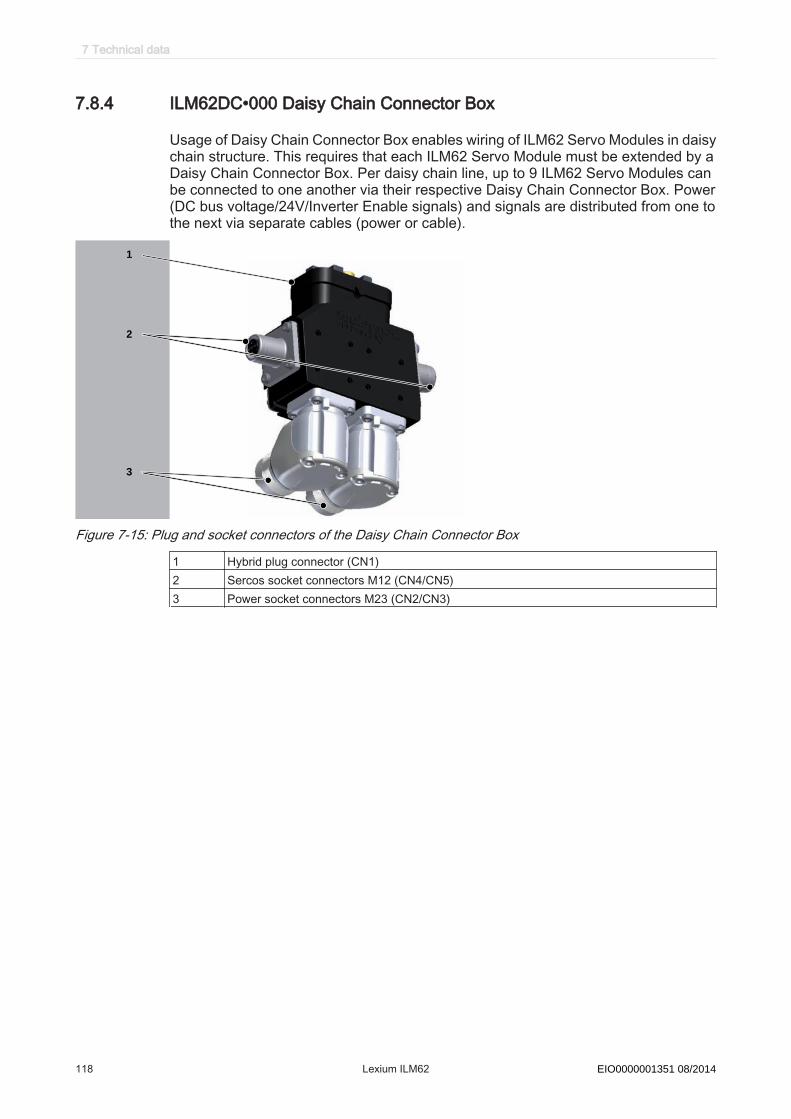
7.8.4 ILM62DC•000 Daisy Chain Connector Box
Usage of Daisy Chain Connector Box enables wiring of ILM62 Servo Modules in daisychain structure. This requires that each ILM62 Servo Module must be extended by aDaisy Chain Connector Box. Per daisy chain line, up to 9 ILM62 Servo Modules canbe connected to one another via their respective Daisy Chain Connector Box. Power(DC bus voltage/24V/Inverter Enable signals) and signals are distributed from one tothe next via separate cables (power or cable).
TM
1
2
3
Figure 7-15: Plug and socket connectors of the Daisy Chain Connector Box
1 Hybrid plug connector (CN1)2 Sercos socket connectors M12 (CN4/CN5)3 Power socket connectors M23 (CN2/CN3)
7 Technical data
118 Lexium ILM62 Schneider Electric 08/2014EIO0000001351 08/2014

8
66 77
1010 1212
1313
1111
1...51...5
9
View
mating side
Pin Designation Meaning1 IE_sig Inverter Enable
(differential signal)2 IE_ref3 Brake Braking signal4 n.c. -5 n.c. -6 24V Control voltage 24V7 0V Control voltage 0V8.1 Rx+ Sercos port 1 – input8.2 Tx- Sercos port 1 – output8.3 Rx- Sercos port 1 – input8.4 Tx+ Sercos port 1 – output9.1 Rx+ Sercos port 2 – input9.2 Tx- Sercos port 2 – output9.3 Rx- Sercos port 2 – input9.4 Tx+ Sercos port 2 – output10 DC- DC bus voltage -11 n.c. -12 DC + Dc bus voltage +13 PE Protective conductor
Table 7-33: Hybrid plug connector (CN1)
2
134 5
6
7
Pin Designation Meaning1 DC + Dc bus voltage +2 PE Protective conductor3 DC- Dc bus voltage +4 24V Control voltage 24V5 0V Control voltage 0V6 IE_sig Inverter Enable signal 17 IE_ref Inverter Enable signal 2
Table 7-34: Power socket connector M23 (CN2/CN3) of Daisy Chain Connector Box
2
34
1
Pin Designation Meaning1 Eth_Tx+ Positive transceiver signal2 Eth_Rx+ Positive receiver signal3 Eth_Tx- Negative transceiver signal4 Eth_Rx- Negative receiver signal
Table 7-35: Sercos socket connector M12 (CN4/CN5) of Daisy Chain Connector Box
7.8 Electrical connections
Schneider Electric 08/2014 Lexium ILM62 119EIO0000001351 08/2014
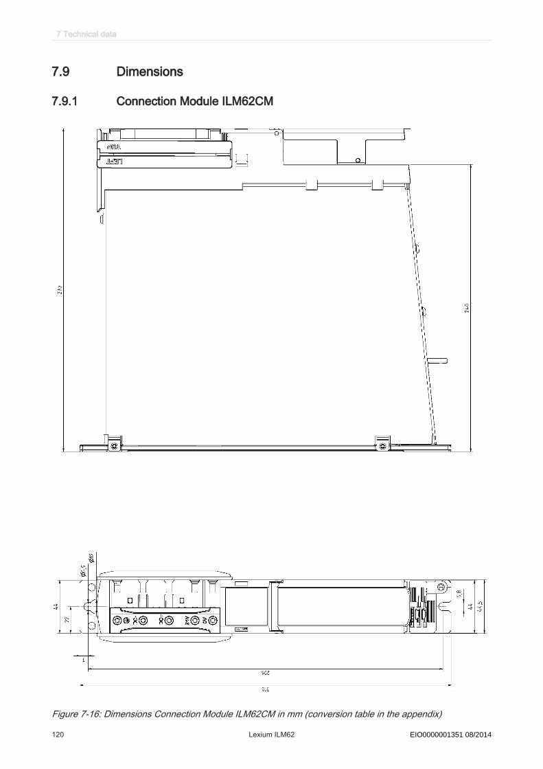
7.9 Dimensions
7.9.1 Connection Module ILM62CM
Figure 7-16: Dimensions Connection Module ILM62CM in mm (conversion table in the appendix)
7 Technical data
120 Lexium ILM62 Schneider Electric 08/2014EIO0000001351 08/2014
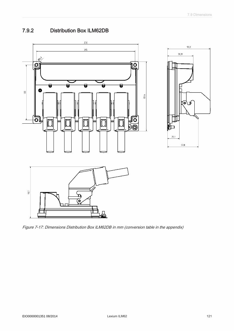
7.9.2 Distribution Box ILM62DB
Figure 7-17: Dimensions Distribution Box ILM62DB in mm (conversion table in the appendix)
7.9 Dimensions
Schneider Electric 08/2014 Lexium ILM62 121EIO0000001351 08/2014
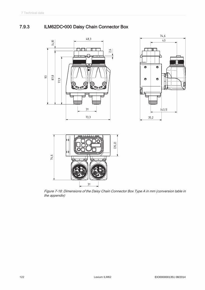
7.9.3 ILM62DC•000 Daisy Chain Connector Box
93
74,6
43
74,6
31
77,9
4,8
()
35,2
()35,273,3
43,1( )
87,8
31
48,3
2,6
Figure 7-18: Dimensions of the Daisy Chain Connector Box Type A in mm (conversion table inthe appendix)
7 Technical data
122 Lexium ILM62 Schneider Electric 08/2014EIO0000001351 08/2014
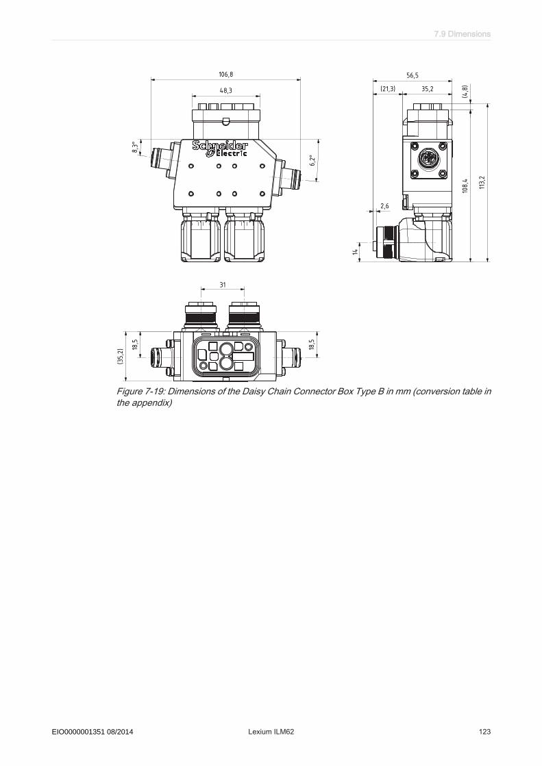
106,8 56,5
35,221,3( )
2,6
113,2
108,4
48,3
31
18,5
18,5
14
35,2
()
4,8
()
6,2°
8,3°
Figure 7-19: Dimensions of the Daisy Chain Connector Box Type B in mm (conversion table inthe appendix)
7.9 Dimensions
Schneider Electric 08/2014 Lexium ILM62 123EIO0000001351 08/2014

35,2
35,2
()
140,2
31
135,4
21,3( )
56,5
2,6
106,8
48,3 4,8
()
14
18,5
18,5
6,2°
8,3°
Figure 7-20: Dimensions of the Daisy Chain Connector Box Type C in mm (conversion tablein the appendix)
7 Technical data
124 Lexium ILM62 Schneider Electric 08/2014EIO0000001351 08/2014

7.9.4 ILM62 Servo Module
Dimensions ILM070
with Option-module
without Option-module
Figure 7-21: Dimensions ILM070 motor in mm (conversion table in the appendix)
Please note that the ILM series 070 uses different shaft diameters. The shaft diameterfor the ILM070 3 P is 14mm .
Dimensions table
Dimensions ILM070 1 P ILM070 2 P ILM070 3 PA (with brake) 175 (182) 189 (215) 222 (256)B 23 23 30C 11 k6 11 k6 14 k6K (with brake) 212 (219) 226 (252) 259 (293)L (with brake) 25 (31) 38 (64) 71 (105)
Table 7-36: Dimensions of the ILM070 (dimension specifications in mm)
7.9 Dimensions
Schneider Electric 08/2014 Lexium ILM62 125EIO0000001351 08/2014

Dimensions ILM100without Option-module
with Option-module
Figure 7-22: Dimensions ILM100 motor in mm (conversion table in the appendix)
Dimensions table
Dimensions ILM100 1 P ILM100 2 P ILM100 3 PA (with brake) 178 (207) 212 (243) 248 (279)B 40 40 40C 19 k6 19 k6 19 k6K (with brake) 215 (243) 249 (280) 285 (315)L (with brake) 27 (55) 61 (92) 97 (127)
Table 7-37: Dimensions of the ILM100 (dimension specifications in mm)
7 Technical data
126 Lexium ILM62 Schneider Electric 08/2014EIO0000001351 08/2014
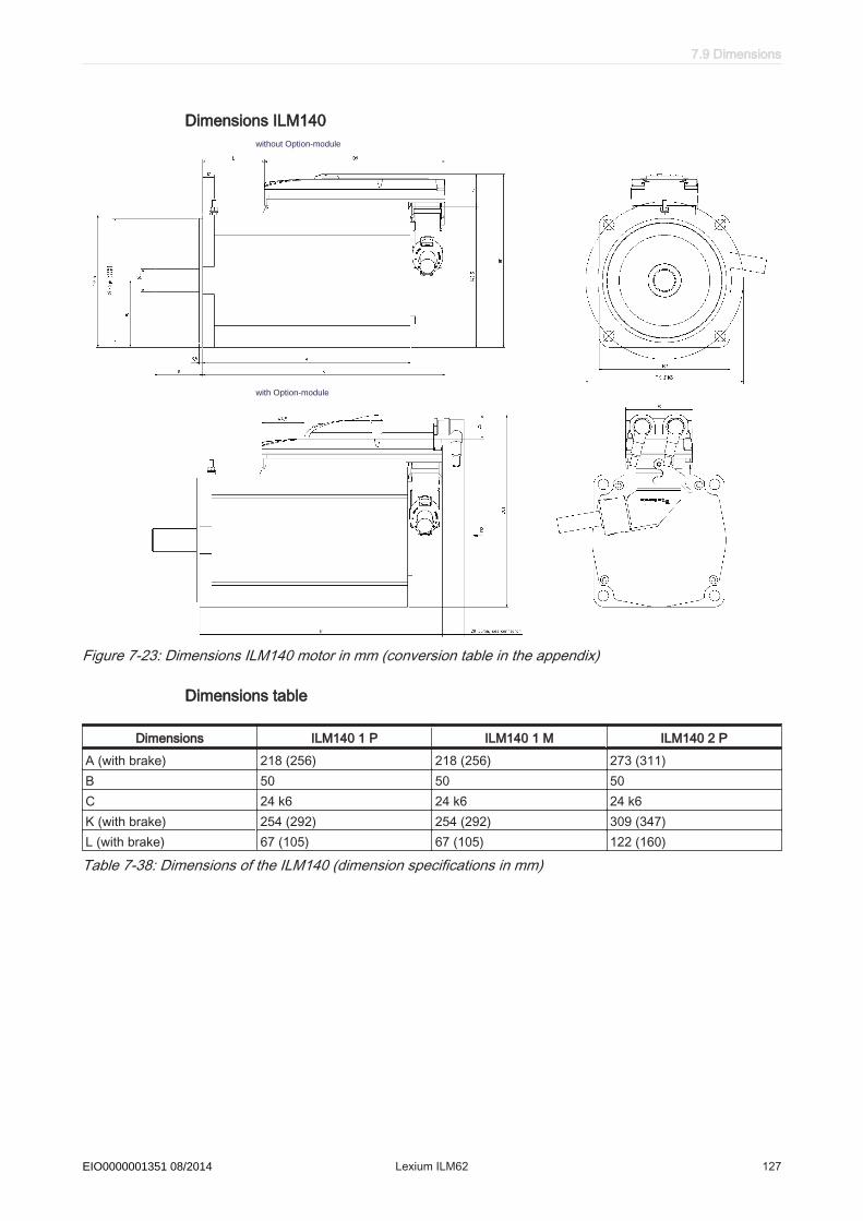
Dimensions ILM140without Option-module
with Option-module
Figure 7-23: Dimensions ILM140 motor in mm (conversion table in the appendix)
Dimensions table
Dimensions ILM140 1 P ILM140 1 M ILM140 2 PA (with brake) 218 (256) 218 (256) 273 (311)B 50 50 50C 24 k6 24 k6 24 k6K (with brake) 254 (292) 254 (292) 309 (347)L (with brake) 67 (105) 67 (105) 122 (160)
Table 7-38: Dimensions of the ILM140 (dimension specifications in mm)
7.9 Dimensions
Schneider Electric 08/2014 Lexium ILM62 127EIO0000001351 08/2014

Dimensions of the feather key
Figure 7-24: Dimension diagram of the feather key
Dimension tables
Dimensions ILM070 1 P ILM070 2 P ILM070 3 PB 23 23 30C 11 k6 11 k6 14 k6D 4 N9 4 N9 5 N9E 2.5 2.5 3F 18 18 20G 2.5 2.5 5H DIN 332-D M4 DIN 332-D M4 DIN 332-D M5Feather key (N9) DIN 6885-A4x4x18 DIN 6885-A4x4x18 DIN 6885-A5x5x20
Table 7-39: Dimensions of the ILM070 feather key (dimension specifications in mm)
Dimensions ILM100 1 P ILM100 2 P ILM100 3 PB 40 40 40C 19 k6 19 k6 19 k6D 6 N9 6 N9 6 N9E 3.5 3.5 3.5F 30 30 30G 5 5 5H DIN 332-D M6 DIN 332-D M6 DIN 332-D M6Feather key (N9) DIN 6885-A6x6x30 DIN 6885-A6x6x30 DIN 6885-A6x6x30
Table 7-40: Dimensions of the ILM100 feather key (dimension specifications in mm)
Dimensions ILM140 1 P ILM140 1 M ILM140 2 PB 50 50 50C 24 k6 24 k6 24 k6D 8 N9 8 N9 8 N9E 4.5 4.5 4.5F 40 40 40G 5 5 5
7 Technical data
128 Lexium ILM62 Schneider Electric 08/2014EIO0000001351 08/2014
Dimensions ILM140 1 P ILM140 1 M ILM140 2 PH DIN 332-D M8 DIN 332-D M8 DIN 332-D M8Feather key (N9) DIN 6885-A8x7x40 DIN 6885-A8x7x40 DIN 6885-A8x7x40
Table 7-41: Dimensions of the ILM140 feather key (dimension specifications in mm)
7.9 Dimensions
Schneider Electric 08/2014 Lexium ILM62 129EIO0000001351 08/2014
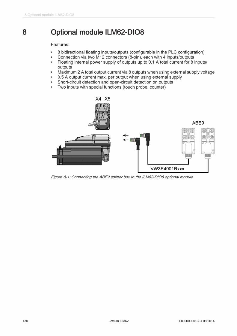
8 Optional module ILM62-DIO8Features:
• 8 bidirectional floating inputs/outputs (configurable in the PLC configuration)• Connection via two M12 connectors (8-pin), each with 4 inputs/outputs• Floating internal power supply of outputs up to 0.1 A total current for 8 inputs/
outputs• Maximum 2 A total output current via 8 outputs when using external supply voltage• 0.5 A output current max. per output when using external supply• Short-circuit detection and open-circuit detection on outputs• Two inputs with special functions (touch probe, counter)
Figure 8-1: Connecting the ABE9 splitter box to the ILM62-DIO8 optional module
8 Optional module ILM62-DIO8
130 Lexium ILM62 Schneider Electric 08/2014EIO0000001351 08/2014

8.1 Technical data
Parameter ValueItem name VW3E702100000ILM62-DIO8supply- Control voltage / control current DC 24 V (-15% / +20%)
when using internal I/O supply: max. 300mA when using external I/O supply: max. 80mA
digital inputs - Number- Voltage in UIN 0 range- Voltage in UIN 1 range - Input current- Electrical isolation- Protected against reverse polarity- Input filter
8 (IEC61131-2 Type I)DC -3 ... 5 VDC 15 ... 30 VIIN = 2 mA at UIN = 15 V500 V floating opposite PEYes 1 or 5 ms, configurable
Digital outputs - Number- Output voltage- Rated current per output- Overall module current across all 8 in-/outputs
- Inrush current- Leakage current with 0 signal- Transmission time- Short-circuit-proof- Supply output- Galvanic isolation
8 (IEC61131-2) (+UL-3 V) < UOUT < +UL
Ie = 500 mAWhen using internal I/O supply: 0.1 A When using external I/O supply: 2.0 A Iemax > 2 A for 1 s< 0.4 mA100 µsYesDC 24 V (-15% / +20%) / 2 A500 V floating opposite PE
Weight 0,22 kg Ambient conditions - Degree of protection- Ambient temp. during operation- During storage and transport- Overvoltage category
- Degree of radio interference
IP 65+5...+40°C -25...+70°C , Temperature fluctuation tmax = 30K/h
Class A EN55011 / EN61800-3
Approval CE, cULus
Table 8-1: Technical data of ILM62-DIO8
8.1 Technical data
Schneider Electric 08/2014 Lexium ILM62 131EIO0000001351 08/2014

8.2 Installation
9
1
2
3
4
5
6
7
9
8
10
11
11
8
Figure 8-2: Mounting of the ILM62-DIO8 optional module on the ILM62 Servo Module
1 Torx M3x6 screw2 Protective cover3 O-ring (2.5 x 0.6)4 Protective cover gasket5 Optional module ILM62-DIO86 Sealing ring optional module ILM62-DIO87 ILM62 Servo Module8 Hexagon socket screw key M4x509 Serrated lock washers M4
10 M12 connector11 Hexagon socket screw key M4x28
How to install the optional module ILM62-DIO8:required
tool• Hexagon socket screwdriver 3.0• Torx TX10 screwdriver
▶ Check delivery for completeness:- Optional module ILM62-DIO8 with sealing ring - 2 Torx screws M4x50- 2 x serrated lock washers M4
8 Optional module ILM62-DIO8
132 Lexium ILM62 Schneider Electric 08/2014EIO0000001351 08/2014

NOTICEELECTROSTATIC DISCHARGE
• Touch circuit boards only on edges.• Do not touch any of the circuit points or components.• Before touching the circuit boards you should remove any static loads by first
touching a grounded metallic surface such as the housing.• Do not put the circuit boards on a metal surface.• Avoid the production of electrostatic charge by having suitable clothing, carpets
and furniture and by moving the boards as little as possible.Failure to follow these instructions can result in equipment damage.
Prepare instal‐lation
▶ Open main switch.▶ Prevent main switch from being switched back on.▶ Loosen the screw (1) with the screwdriver (Torx).▶ Remove screw (1) with insulating washer (3) and protective cap (2) and protective
cap gasket (4) from ILM62 Servo Module.▶ Loosen the screws (11) (M4x28) with the screwdriver (hexagon socket).
NOTICEINSUFFICIENT SHIELDING/GROUNDING/TIGHTNESSThe serrated lock washers (9) must be removed when removing screws (11).Failure to follow these instructions can result in equipment damage.▶ Remove the screws (11) with serrated lock washers (9).
Assemble ▶ Insert the sealing ring (6) into the groove of the ILM62-DIO8.
NOTICEINCORRECT INSTALLATION
• Align ILM62-DIO8 with the three fixing pins.• Insert the sealing ring of ILM62-DIO8 completely into the groove.Failure to follow these instructions can result in equipment damage.▶ Attach ILM62-DIO8 on ILM62 Servo Module.▶ Plug screws (8) (M4x50) with serrated lock washers (9) through ILM62-DIO8 into
ILM62 Servo Module.▶ Gently turn the screw (8) inward with a screwdriver (hexagon socket).▶ Tighten the screws (8) temporary with 2 Nm (17.70 lbf in).▶ Tighten the screws (8) with 3 Nm (35.40 lbf in) definitively.▶ Fit protective cap (2) together with protective cover seal (4) onto ILM62-DIO8.▶ Screw the protective cap on tightly (to 1 Nm) with the screw (1) and the insulating
washer (3) by using a Torx screwdriver.
8.2 Installation
Schneider Electric 08/2014 Lexium ILM62 133EIO0000001351 08/2014

8.3 Electrical connections
Optional module ILM62-DIO8
Pin Designation Meaning1 IO.0 Input/output 02 IO.1 Input/output 13 IO.2 Input/output 24 IO.3 Input/output 35 24 V Control voltage6 24 V Control voltage7 0 V Control voltage8 0 V Control voltageShield PE Shield
Table 8-2: Electrical connections ILM62-DIO8 outlet X4 - inputs/outputs
Pin Designation Meaning1 IO.4 Input/output 42 IO.5 Input/output 53 IO.6 Input/output 64 IO.7 Input/output 75 24 V Control voltage6 24 V Control voltage7 0 V Control voltage8 0 V Control voltageShield PE Shield
Table 8-3: Electrical connections ILM62-DIO8 outlet X5 - inputs/outputs
Block diagram ILM62-DIO8
in -/ output
DC
DC
PowerSupply (intern)
24V
internal adressing
X4.5 X4.6
X5.5 X5.6
X4.7 X4.8
X5.7 X5.8
X4.1 X4.2 X4.3 X4.4
X5.1 X5.2 X5.3 X5.4
2A max. 24V
24V
0V
IO.0
IO.1
IO.2
IO.3
IO.4
IO.5
IO.6
IO.7
2A max.
X4 X5
ILM62-DIO8
Figure 8-3: Block diagram ILM62-DIO8
8 Optional module ILM62-DIO8
134 Lexium ILM62 Schneider Electric 08/2014EIO0000001351 08/2014

ABE9 Splitter Box
outlet 3 4 outlet
outlet 1 2 outlet
Figure 8-4: Connection scheme ABE9 splitter box
Pin Designation Meaning1 24 V Control voltage2 free Reserved3 0 V Control voltage4 IO.x Input/output x (X4: 0 ... 3 or X5: 4 ... 7)5 PE Shield
Table 8-4: Electrical connections for ABE9 Splitter Box outlet 1 ... 4 - Inputs/Outputs
The control voltage when using external I/O supply can be supplied either via the X4,X5 outlets or via the ABE9 Splitter Box.
NOTICENO POTENTIAL ISOLATION OF THE INPUTS/OUTPUTSWhen using an external power supply, you must protect it with 2 A slow blow fuse.Failure to follow these instructions can result in equipment damage.
1
2
3
4
5 1
2
3
4
5 1
2
3
4
5 1
2
3
4
5
PE -1 -2 +1 +2 1 2 3 4
shield blue red grey pink white brown green yellow
outlet 1 outlet 2 outlet 3 outlet 4
*)
*) 2 variants available: with or without LED indicator
Figure 8-5: Block diagram ABE9 splitter box
8.3 Electrical connections
Schneider Electric 08/2014 Lexium ILM62 135EIO0000001351 08/2014
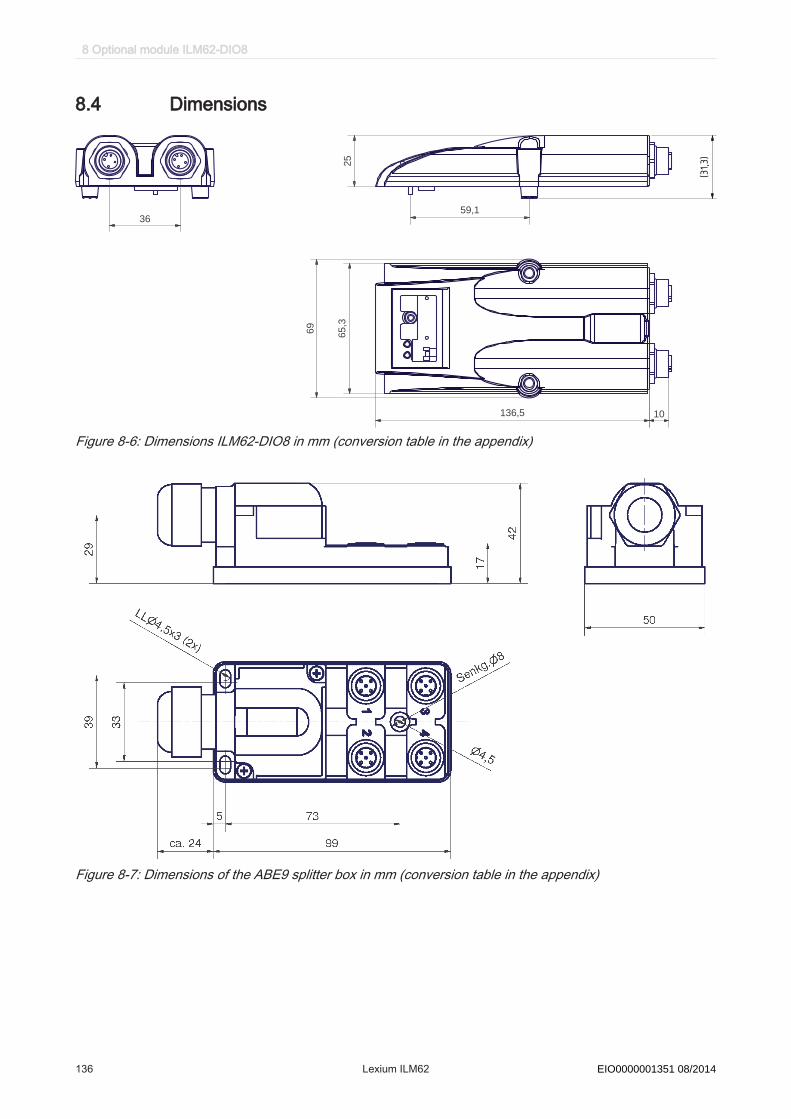
8.4 Dimensions
25
59,1
65,3
69
136,5 10
36
(31,3)
Figure 8-6: Dimensions ILM62-DIO8 in mm (conversion table in the appendix)
Figure 8-7: Dimensions of the ABE9 splitter box in mm (conversion table in the appendix)
8 Optional module ILM62-DIO8
136 Lexium ILM62 Schneider Electric 08/2014EIO0000001351 08/2014

8.5 Wiring
-1
+1
1
3
PE
4
2
+2
-2
blue
gray
white
green
Shield
yellow
brown
pink
red
KA99051 - xxx
Figure 8-8: Cable configuration VW3E4001Rxxx for connection of ABE9 splitter box
24 V DC
M12-5 pin
M12-8 pin
Figure 8-9: 2-4 inputs/ outputs with external supply
M12-5 pinM12-8 pin
24 V DC
Figure 8-10: 5-7 inputs/ outputs with external supply
8.5 Wiring
Schneider Electric 08/2014 Lexium ILM62 137EIO0000001351 08/2014
9 Appendix
9.1 Contact addresses
Schneider Electric Automation GmbHSchneiderplatz 197828 Marktheidenfeld, GermanyPhone: +49 (0) 9391 / 606 - 0Fax: +49 (0) 9391 / 606 - 4000Email: [email protected]: www.schneider-electric.com
Machine Solution ServiceSchneiderplatz 197828 Marktheidenfeld, GermanyPhone: +49 (0) 9391 / 606 - 3265Fax: +49 (0) 9391 / 606 - 3340Email: [email protected]: www.schneider-electric.com
See the homepage for additional contact addresses:www.schneider-electric.com
9.2 Product training courses
Schneider Electric offers a number of product training courses.Our training instructors will help you take advantage of the extensive possibilities of‐fered by the system.
See the homepage (www.schneider-electric.com) for further information and our cur‐rent seminar schedule.
9.3 Disposal
The components consist of different materials, which can be re-used and must bedisposed of separately. The packaging cannot be returned to the manufacturer.
▶ Dispose of the packaging in accordance with the relevant national regulations.▶ Dispose of the packaging at the disposal sites provided for this purpose.▶ Dispose of ILM62 components in accordance with the applicable national regu‐
lations.
9 Appendix
138 Lexium ILM62 Schneider Electric 08/2014EIO0000001351 08/2014
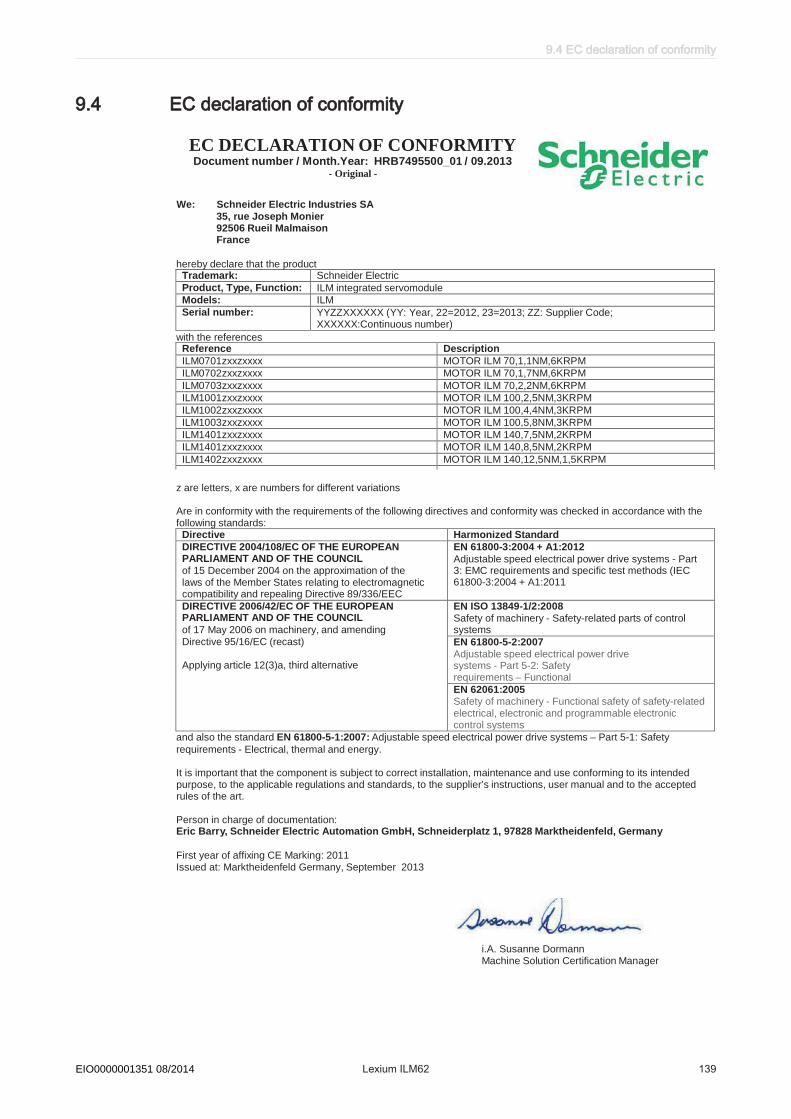
9.4 EC declaration of conformity
EC DECLARATIONOF CONFORMITYDocument number / Month.Year: HRB7495500_01 / 09.2013
i.A. Susanne DormannMachine Solution Certification Manager
Trademark: Schneider Electric
Product, Type, Function: ILM integrated servomodule
Models: ILM
Serial number: YYZZXXXXXX (YY: Year, 22=2012, 23=2013; ZZ: Supplier Code;XXXXXX:Continuous number)
Reference Description
ILM0701zxxzxxxx MOTOR ILM 70,1,1NM,6KRPM
ILM0702zxxzxxxx MOTOR ILM 70,1,7NM,6KRPM
ILM0703zxxzxxxx MOTOR ILM 70,2,2NM,6KRPM
ILM1001zxxzxxxx MOTOR ILM 100,2,5NM,3KRPM
ILM1002zxxzxxxx MOTOR ILM 100,4,4NM,3KRPM
ILM1003zxxzxxxx MOTOR ILM 100,5,8NM,3KRPM
ILM1401zxxzxxxx MOTOR ILM 140,7,5NM,2KRPM
ILM1401zxxzxxxx MOTOR ILM 140,8,5NM,2KRPM
ILM1402zxxzxxxx MOTOR ILM 140,12,5NM,1,5KRPM
Directive Harmonized Standard
DIRECTIVE 2004/108/EC OF THE EUROPEANPARLIAMENT AND OF THE COUNCILof 15 December 2004 on the approximation of thelaws of the Member States relating to electromagneticcompatibility and repealing Directive 89/336/EEC
EN 61800-3:2004 + A1:2012
Adjustable speed electrical power drive systems - Part3: EMC requirements and specific test methods (IEC61800-3:2004 + A1:2011
DIRECTIVE 2006/42/EC OF THE EUROPEANPARLIAMENT AND OF THE COUNCIL
of 17 May 2006 on machinery, and amending
Directive 95/16/EC (recast)
Applying article 12(3)a, third alternative
EN ISO 13849-1/2:2008Safety of machinery - Safety-related parts of controlsystems
EN 61800-5-2:2007Adjustable speed electrical power drivesystems - Part 5-2: Safetyrequirements – Functional
EN 62061:2005Safety of machinery - Functional safety of safety-relatedelectrical, electronic and programmable electroniccontrol systems
- Original -
We: Schneider Electric Industries SA35, rue Joseph Monier92506 Rueil MalmaisonFrance
hereby declare that the product
with the references
z are letters, x are numbers for different variations
Are in conformity with the requirements of the following directives and conformity was checked in accordance with thefollowing standards:
and also the standard EN 61800-5-1:2007: Adjustable speed electrical power drive systems – Part 5-1: Safety
requirements - Electrical, thermal and energy.
It is important that the component is subject to correct installation, maintenance and use conforming to its intendedpurpose, to the applicable regulations and standards, to the supplier’s instructions, user manual and to the acceptedrules of the art.
Person in charge of documentation:Eric Barry, Schneider Electric Automation GmbH, Schneiderplatz 1, 97828 Marktheidenfeld, Germany
First year of affixing CE Marking: 2011Issued at: Marktheidenfeld Germany, September 2013
9.4 EC declaration of conformity
Schneider Electric 08/2014 Lexium ILM62 139EIO0000001351 08/2014

9.5 Units and conversion tables
9.5.1 Length
in ft yd m cm mmin - / 12 / 36 * 0.0254 * 2.54 * 25.4ft * 12 - /3 * 0.30479 * 30.479 * 304.79yd * 36 * 3 - * 0.9144 * 91.44 * 914.4m / 0.0254 / 0.30479 / 0.9144 - *100 * 1000cm / 2.54 / 30.479 / 91.44 / 100 - * 10mm / 25.4 / 304.79 / 914.4 / 1000 / 10 -
9.5.2 Mass
lb oz slug 0.22 kg glb - * 16 * 0.03108095 * 0.4535924 * 453.5924oz / 16 - * 1.942559*10-3 * 0.02834952 * 28.34952slug / 0.03108095 / 1.942559*10-3 - * 14.5939 * 14593.90.22 kg / 0.45359237 / 0.02834952 / 14.5939 - * 1000g / 453.59237 / 28.34952 / 14593.9 / 1000 -
9.5.3 Force
lb oz p dyne Nlb - * 16 * 453.55358 * 444822.2 * 4.448222oz / 16 - * 28.349524 * 27801 * 0.27801p / 453.55358 / 28.349524 - * 980.7 * 9.807*10-3
dyne / 444822.2 / 27801 / 980.7 - / 100*103
N / 4.448222 / 0.27801 / 9.807*10-3 * 100*103 -
9.5.4 Power
HP WHP - * 746W / 746 -
9.5.5 Rotation
min-1(rpm) rad/s deg./smin-1(rpm) - * π / 30 * 6rad/s * 30 / π - * 57.295deg./s / 6 / 57.295 -
9 Appendix
140 Lexium ILM62 Schneider Electric 08/2014EIO0000001351 08/2014

9.5.6 Torque
lb•in lb•ft oz•in Nm kp•m kp•cm dyne•cmlb•in - / 12 * 16 * 0.112985 * 0.011521 * 1.1521 * 1.129*106
lb•ft * 12 - * 192 * 1.355822 * 0.138255 * 13.8255 * 13.558*106
oz•in / 16 / 192 - * 7.0616*10-3 * 720.07*10-6 * 72.007*10-3 * 70615.5Nm / 0.112985 / 1.355822 / 7.0616*10-3 - * 0.101972 * 10.1972 * 10*106
kp•m / 0.011521 / 0.138255 / 720.07*10-6 / 0.101972 - * 100 * 98.066*106
kp•cm / 1.1521 / 13.8255 / 72.007*10-3 / 10.1972 / 100 - * 0.9806*106
dyne•cm / 1.129*106 / 13.558*106 / 70615.5 / 10*106 / 98.066*106 / 0.9806*106 -
9.5.7 Moment of inertia
lb•in2 lb•ft2 kg•m2 kg•cm2 kg•cm2•s2 oz•in2
lb•in2 - / 144 / 3417.16 / 0.341716 / 335.109 * 16lb•ft2 * 144 - /3 *0.30479 *30.479 *304.79kg•m2 * 3417.16 / 0.04214 - *0.9144 *91.44 *914.4kg•cm2 * 0.341716 / 421.4 /0.9144 - *100 *1000kg•cm2•s2 * 335.109 / 0.429711 /91.44 /100 - *10oz•in2 / 16 / 2304 / 54674 / 5.46 / 5361.74 -
9.5.8 Temperature
°F max K°F - (°F - 32) * 5/9 (°F - 32) * 5/9 + 273.15max °C * 9/5 + 32 - °C + 273.15K (K - 273.15) * 9/5 + 32 K - 273.15 -
9.5.9 Conductor cross-section
AWG 1 2 3 4 5 6 7 8 9 10 11 12 13mm2 42.4 33.6 26.7 21.2 16.8 13.3 10.5 8.4 6.6 5.3 4.2 3.3 2.6
AWG 14 15 16 17 18 19 20 21 22 23 24 25 26mm2 2.1 1.7 1.3 1.0 0.82 0.65 0.52 0.41 0.33 0.26 0.20 0.16 0.13
9.5 Units and conversion tables
Schneider Electric 08/2014 Lexium ILM62 141EIO0000001351 08/2014

Index
BBending cycles 38Brake 103
CCertifications 93Cleaning 78Cleaning agents 78Climatic 35Condensate 36Contact addresses 138Cooling units 36
DDaisy Chain Connector Box 18Daisy chain wiring 18Definitions 88Degree of protection 35domestic appliances 9
EEmergency stop 45
FFan cover 94floating systems 9flying systems 9Force ventilation 94
GGrind holding brake 61
HHazard and risk analysis 42, 54hazardous, explosive atmospheres 9Hazards 10Homepage 138
IInstallation 48Inverter Enable input 47InverterEnable input 44
Llife support systems 9
MMachine grounding 37Maximum configuration 48Mechanical 35Minimum bending radius 38Minimum cross sections 37Misuse 54mobile systems 9Motor shaft 102Muting 45
PPhysical sizes 88portable systems 9
QQualification of Personnel 10Qualified person 10
RResidual risks 10
SSafe state 44Safe stop 43Safety function 44Safety wiring 51Seminars 138Service addresses 138Shaft 102Standards 56Stop category 0 43, 45Stop category 1 43, 45Surface ventilation 94Symbols 8
TTechnical data 94, 95, 96, 97, 98, 99, 100Temperature limit 36Training 10Training courses 138
Index
142 Lexium ILM62 Schneider Electric 08/2014EIO0000001351 08/2014

Uunderground 9
WWiring 37
Index
Schneider Electric 08/2014 Lexium ILM62 143EIO0000001351 08/2014