operating manual mid-frequency transformer-rectifier units ... · - staff engaged on project work...
TRANSCRIPT

Operating manual for Mid-frequency transformer-rectifier units 15.10.2013
Operating Manual
Mid-frequency transformer-rectifier units
for resistance welding (MFDC)

Operating Manual
Mid-frequency transformer-rectifier units for resistance welding
General
Operating manual for Mid-frequency transformer-rectifier units 15.10.2013
Table of contents
1 General 3
2 Notes on Safety 4
2.1 General Notes................................................................................................. 4
2.2 Protection against direct or indirect contract with electrically conductive parts5
2.2.1 Protection against direct contact ..................................................................... 5
2.2.2 Protection against indirect contact in case of fault .......................................... 6
2.3 Protection against the effects of electro-magnetic fields ................................. 8
3 Technical data 10
3.1 General ......................................................................................................... 10
3.2 Rating plate data ........................................................................................... 11
4 Using the MFDCs as specified 12
4.1 Field of applications for MFDCs .................................................................... 12
4.2 Materials for resistance welding, the resistance welding process ................. 13
4.4 Connection variants of MFDCs ..................................................................... 17
4.6 General requirements for welding inverters and control units ....................... 18
4.7 Electrodynamic forces on welding circuit and secondary connections .......... 18
4.8 Power connection of MF welding equipment ................................................ 20
5 Design and function of MFDCs 21
5.1 Design of an MF transformer-rectifier unit .................................................... 21
5.2 Auxiliary circuits ............................................................................................ 21
5.2.1 Temperature monitoring ............................................................................... 21
5.2.2 Welding current monitoring, constant-current control ................................... 23
5.2.3 Secondary circuit monitoring ........................................................................ 23
5.2.4 Voltage monitoring ........................................................................................ 24
6 Transport and storage 25
6.1 Transport ...................................................................................................... 25

Operating Manual
Mid-frequency transformer-rectifier units for resistance welding
Table of contents
2
6.2 Storage ......................................................................................................... 27
7 Installation, electrical connections and start-up 28
7.1 Mounting and electrical installation ............................................................... 28
7.2 Permissible ambient conditions .................................................................... 31
8 Notes on the operating MFDCs 31
8.1 Coolant water quality .................................................................................... 31
8.2 Coolant water quantity, differential pressure in the cooling circuit ................ 33
9 Maintenance 34
9.1 Primary and secondary terminals ................................................................. 34
9.2 Rectifier unit .................................................................................................. 35
9.3 Cooling circuit ............................................................................................... 35
10 Literature 37
10.1 Industrial standards and regulations ............................................................. 37
10.2 DVS guidelines and instruction leaflets ......................................................... 38

Operating Manual
Mid-frequency transformer-rectifier units for resistance welding
General
Operating manual for Mid-frequency transformer-rectifier units 15.10.2013 3
1 General
These operating instructions on mid-frequency transformer-rectifier units for re-
sistance-welding contain not only the technical description of the products, referred to
hereinafter as MFDCs, but also important information for their selection, handling,
assembly, and installation, so as to ensure the highest possible level of safety for
people and machinery as well as the correct and proper function.
The following European Union Directives apply to the product and its intended use:
73/23/EEC Electrical equipment for use within certain voltage limits (the “Low-Voltage
Directive”)
89/336/EEC Electromagnetic compatibility
89/392/EEC Safety of machines (the “Machinery Directive”)
93/68/EEC CE-marking (electrical safety label)
Apart from this the national regulations for the construction and operation of electrical
equipment and the relevant safety regulations have to be observed.
The user has to be given the following necessary safety instructions (see Section 2).
These operating manual are intended for the following groups of users:
- staff engaged on project work and design engineering
- installation and commissioning personnel
- staff responsible for maintenance and repair
- staff in transportation and storage departments.

Operating Manual
Mid-frequency transformer-rectifier units for resistance welding
Notes on Safety
Operating manual for Mid-frequency transformer-rectifier units 15.10.2013 4
2 Notes on Safety
2.1 General Notes
Safe and faultless operation is not possible without the proper transportation, correct
storage, assembly, and installation, and careful operation and maintenance.
MFDCs are intended for installation in machinery and equipment in the commercial
field. The specific safety regulations and requirements for the relevant instance of
use have to be observed.
The operation of MFDCs is only permitted if effective precautions have been taken
against indirect contact with live electrical parts occurring in the case of a fault. This
includes temporary use for inspection and testing purposes.
Conducting parts have to be securely covered to prevent contact with persons before
MFDCs are switched on.
The machine or the production line must be brought into a state before installation or
maintenance work starts, e.g. its basic setting, that allows the work to be done with-
out any danger.
The part of the machine or line on which the work is to be done must be switched off.
Under certain circumstances residual voltage can remain and in such case the prima-
ry and secondary sides should be disconnected. Attention should be paid to moving
parts on adjacent parts of the line that could give rise to danger. If any such danger
exists the adjacent parts of the line should also be disconnected.
Note: Working component groups based on a semi-conductor such as thyristors or
isolated gate bipolar transistors (IGBTs) sometimes prevent any electrical separation
of the circuit even when the control unit is switched off. The master switch must also
be turned off as well.
Switches that have been used for switching off the current must be protected against
being inadvertently switched on again. Equipment should be marked with signs
worded (e.g.) as “DO NOT SWITCH ON – repair work in progress” and stating the
period of time of the work and the employee responsible for it.

Operating Manual
Mid-frequency transformer-rectifier units for resistance welding
Notes on Safety
5
Freedom from electrical tension on all poles of MFDCs must be checked with suitable
measurement and control instrumentation such as voltage tests and measurers.
Adjacent parts that are still “live” must be covered.
Machines and production lines must be brought into the state described above before
anyone enters them or even puts a hand inside them, e.g. by opening the safety
doors.
The supply of coolant water should also be shut off.
2.2 Protection against direct or indirect contract with electrically conductive
parts
2.2.1 Protection against direct contact
When MFDCs are being used on welding equipment, certain components such as the
accessible part of the welding circuit or the welding part necessarily come into contact
with the low-voltage side of the MFDC. Contact with these parts releases operating
voltages up to the level of the secondary idling voltage.
Generally speaking these voltages lie below the limit for permissible contact voltages.
Under DIN VDE 0100 part 410 the maximum levels for contact voltages are defined as:
AC equipment (50 - 60Hz) UL = 25V
DC equipment UL = 60V
Danger from excessively high contact voltage
If the secondary coils of one or more MFDCs are connected in series, higher voltages can be generated than those permissible for contact. If cascading results in excessive voltages, the user has to take suitable safety precautions against direct contact, e.g. by covering or closing the cladding.
The maximum permissible contact voltages defined in DIN VDE 0100 Part 410 apply to
applications in dry rooms.

Operating Manual
Mid-frequency transformer-rectifier units for resistance welding
Notes on Safety
6
Touching “live” parts with the whole of a wet hand can result in a perceptible electric
shock even at voltages below 10V.
This fact has to be borne in mind in the design of welding guns, particularly those oper-
ated by hand.
All metal parts that can conduct electricity and can be touched must have an earth con-
nection. Gun arms with potential should have additional insulating sleeves, wrappings,
or similar, so that for instance when two people are working on the machine there is no
possibility of the two gun arms coming into contact.
In addition to this the operating personnel should also wear suitable gloves.
Touching “live” parts with the whole of a wet hand can result in a serious electric shock even at AC or DC voltages below 10V. Gun arms with potential must be properly covered.
2.2.2 Protection against indirect contact in case of fault
The transformers in EXPERT MFDCs meet the requirements for Safety Category 1 of
DIN VDE 0551 Part 1 I.
As protection against excessively high contact voltages in the event of a fault (protection
against indirect contact), additional safety precautions have to be taken in accordance
with EN 62135-1 (DIN VDE 0545, Part 1) such as connecting the secondary circuits to
earth and installing r.c.d.
All the housing parts of the MFDC must be electrical connected via the primary side
earth connection to the main earth connection.
Safety precautions against indirect contact
The secondary circuits of the MFDC generally speaking should not be connected to the main earth because of the many different switching possibilities and the applicability of different safety devices that may be present in the unit in the state in which it is delivered. The user must identify and take the suitable safety precautions necessary under EN 62135-1 (DIN VDE 0545, Part 1.

Operating Manual
Mid-frequency transformer-rectifier units for resistance welding
Notes on Safety
7
The exception to this is the MFDCs that, on account of existing general or the custom-
er’s specific standards, are already fitted in the factory with an internal earth connection,
e.g. MFDCs for guns complying with ISO 10656 or special MFDCs for suspension-point
equipment. This internal earth connection is usually constructed to be detachable and is
identified as MPE.
Please note in any case the data on the information plates of the MFDCs and the in-
structions in the data sheet.
Avoidance of compensation currents
If the necessary safety precautions have been taken by means of a direct connection be-tween the secondary circuit and the earth lead, the user must ensure that no compensation (leakage) currents via the earth lead connection can be caused in complex welding lines by potential displacement during the welding.
The earth conductor must not conduct electricity when the unit is in operation!
Leakage currents can also occur, for instance, if a number of welding current sources
are welding simultaneously on one single work-piece or if welding work is being done
with an MFDC that is already earthed to an additionally earthed work-piece.
When the welding station is being taken into operation, suitable measuring instruments
such as current-consuming guns should be used in order to check that the earth lead is
not carrying any current during the welding work.
Compensation (leakage) currents must always be avoided because they can in an extreme case interrupt the internal earth lead connection.
An interruption in the earth lead connection nullifies the safety precautions and can put human lives in danger.
If leakage currents are the unavoidable result of the direct connection of the secondary
circuit to the protective conductor, in most MFDCs it is possible to disconnect it.
In this case, however, some other safety precaution permitted under EN 62135-1
must be installed to replace it.

Operating Manual
Mid-frequency transformer-rectifier units for resistance welding
Notes on Safety
8
For machinery with r.c.d equipment complying with EN 60947-2 in TN or TT systems (with a nominal fault current ≤ 30mA) MFDCs can be supplied with integral r.c.d. resistance. This has to be checked visually and electrically at regular intervals, at least every six months, to ensure that it is in a faultless condition. It must also be ensured that the r.c.d. protection equipment is suitable for the particular application.
If you have any queries please contact one of the addresses overleaf.
2.3 Protection against the effects of electro-magnetic fields
Magnetic fields are created during resistance-welding, their strength depending on the
level of the welding current and the laws of physics. The greatest concentration of mag-
netic fields can be found in the area of the secondary circuits on account of the level of
the current.
This fact must be taken into account in the design of resistance-welding equipment and
in deciding on the operating positions.
To avoid any possible exceeding of the concentration of electro-magnetic radiation
permissible at a place of work, if necessary it should be technically measured and rec-
orded.
Welding creates not only magnetic fields but also conducted and radiated interference
emissions of electromagnetic waves in a broad range of frequencies. The regulations
laid down in the Electro-Magnetic Directive apply here.
Danger from the effects of electro-magnetic fields
People with medical aids such as heart pace-makers must not come near welding equip-ment or its wiring. There is a risk of the function being disturbed, and under certain circum-stances this could even have fatal consequences or at least seriously harm the person’s health.
Additional instructions:
When welding machines or production lines are being constructed, the limits for elec-
tro-magnetic radiation must be observed (see Appendix: Industrial standards).

Operating Manual
Mid-frequency transformer-rectifier units for resistance welding
Notes on Safety
9
If necessary, suitable protective equipment should be provided such as screening or
alternatively the operating places should be set up at a suitable distance.
The information magnetically stored on data-carriers such as audio and video tape
recorders or even bank and credit cards can be deleted or altered if they come close
to welding machines or production lines.
The magnetic fields created by welding can damage motor-driven precision-
engineering products such as wrist-watches.
Currents can be induced in the immediate vicinity of the welding circuit in metal ob-
jects, even including rings, necklaces, and other jewellery. All according to the
strength of the magnetic field this can lead to the local heating of metal parts and
possible to the risk of burns.
The Electro-Magnetic Compatibility (EMC) Directive guidelines for resistance-welding
equipment have not yet been defined in full detail and there are areas of uncertainty
in their application to welding circuits. Please therefore note the new publications in
the relevant technical literature.

Operating Manual
Mid-frequency transformer-rectifier units for resistance welding
Technical data
Operating manual for Mid-frequency transformer-rectifier units 15.10.2013 10
3 Technical data
3.1 General
The characteristic feature of normal resistance-welding processes such as spot, projec-
tion, and seam welding is that the welding energy is not applied to the welding spots
continuously but in form of pulses.
The necessary welding times are usually far shorter than one second, with long or very
long pauses between the welding pulses all according to the nature of the process.
This mode of operation, called intermittent operation, makes it possible deliberately to
overload the MFDCs that are used as the sources of welding current. This means that,
in contrast to the permissible sustained currents in an MFDC, for short periods of time
far high pulse currents can flow without imposing an excessive thermal load on it. This
in turn makes it possible to produce equipment at the lowest possible cost and weight
that is tailor-made for the specific application. On the other hand, however, this also
means that the deliberate overloading has to be exactly defined in order to ensure total
safety in operation.
The main characteristic for intermittent operation is the percentage duration of the time
when the current is flowing, X, which is the aggregate of the current flow times as a per-
centage of the cycle time T. The relationship can be expressed as a value between 0
and 1 and shown as a percentage. In addition to this the length of the individual welding
pulses is the crucial factor determining the overload capability. Overload behaviour is
shown in diagrams for each type of unit.
The technical data is contained in the relevant data sheets.
The units are subject to technical changes in the interests of technical progress. The
latest documentation should be requested if needed.
Operating Manual
Mid-frequency transformer-rectifier units for resistance welding
Technical data
11
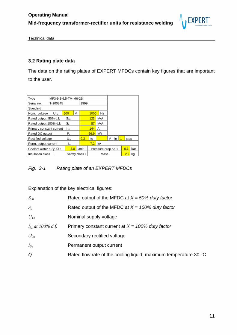
3.2 Rating plate data
The data on the rating plates of EXPERT MFDCs contain key figures that are important
to the user.
Type MF3-9,3-6,5-TM-M6-2B
Serial no. T-100345 1999
Standard
Nom. voltage U1N 500 V 1000 Hz
Rated output, 50% d.f. S50 123 kVA
Rated output 100% d.f. SP 87 kVA
Primary constant current I1P 144 A
Rated DC output Pd 66.9 kW
Rectified voltage U2d 9.3 to V in 1 step
Perm. output current I2d 7.2 kA
Coolant water qu’y Q 8.0 l/min Pressure drop p 0.6 bar
Insulation class F Safety class I Mass 23 kg
Fig. 3-1 Rating plate of an EXPERT MFDCs
Explanation of the key electrical figures:
S50 Rated output of the MFDC at X = 50% duty factor
Sp Rated output of the MFDC at X = 100% duty factor
U1N Nominal supply voltage
I1p at 100% d.f. Primary constant current at X = 100% duty factor
U2d Secondary rectified voltage
I2d Permanent output current
Q Rated flow rate of the cooling liquid, maximum temperature 30 °C

Operating Manual
Mid-frequency transformer-rectifier units for resistance welding
Using the MFDCs as specified
12
4 Using the MFDCs as specified
EXPERT MFDCs have been developed and are manufactured specifically for re-
sistance-welding equipment.
The general construction and technical layout complies with ISO 5826 and ISO 669. In
addition to this they also adhere to the standards applicable to the individual types.
Danger from improper use
Improper use can injure people and damage property and the environment. The high short-circuit currents and similarly high welding energy entail the risk of material evaporation. Never put the MFDCs to any other than the correct and proper use.
4.1 Field of applications for MFDCs
MFDCs consist of the transformer and the rectifier attachment. The electrical parts of
the transformer are fully encapsulated in a resin filling, which means that the coils are
perfectly protected from damp, dirt, and the effects of dynamic current forces. All ac-
cording to the construction, the rectifier attachment can be either open or covered (this
can be seen from the measurements sheet). With the open kinds it is necessary to en-
sure that the rectifier attachment is protected from dirt. MFDCs are components that are
usually constructed to meet the requirements for safety category IP00 on the primary
and the secondary sides (with open terminal points). The construction of the individual
types can be seen from our data sheets.
The MFDCs are not allowed to be used in areas where there is an explosion risk.
Please note the permissible environmental conditions.
Safety category
It is only allowed to use and operate MFDCs in those areas that come into the same safety category (see data sheet). These MFDCs must not be used in areas in which there is an explosion danger.

Operating Manual
Mid-frequency transformer-rectifier units for resistance welding
Using the MFDCs as specified
13
4.2 Materials for resistance welding, the resistance welding process
Definition of resistance welding: see DIN 1910 Part 5
The heat needed for welding is generated by a flow of current across the electrical re-
sistance of the heating zone (resistance heat, calorific heat). The welding can be done
with or without force and with or without a welding additive.
With regard to the definition stated above, the minimum requirement for a material that
is to be welded is that it must conduct electricity. It also must be capable of being weld-
ed in its kneadable form.
Suitable materials:
uncoated steel plate in various thicknesses (often up to 3.0 mm)
coated steel plate, e.g. galvanised
chromium-nickel steel
non-ferrous metals such as aluminium, copper, and silver
Danger from use of wrong materials
The use of materials that cannot be welded or are not recommended can lead to unfore-seeable reactions when the welding energy is applied to the material, and these could cause injury to persons and/or damage to machines.
4.3 Dimensioning of MFDCs
A basic distinction has to be made between:
thermal dimensioning – here the MFDCs are designed in such a way that, in the
individual required case, no overloading occurs through overheating; and
short-circuit dimensioning – there the maximum machine short-circuit current is
calculated between the welding electrodes or the relevant tools.
These two figures are independent of one another and have to be calculated for each
instance of use.
.

Operating Manual
Mid-frequency transformer-rectifier units for resistance welding
Using the MFDCs as specified
14
4.3.1 Thermal dimensioning
The basis is the load diagram with the welding current Is as a function of the relative
duty factor of the current flow X and the welding time ts. The load diagrams are a com-
ponent part of the documentation.
Because of the different thermal time-constants, the diodes and the transformer load
have to be looked at separately. If you have any queries please contact us at one of the
addresses given at the end.
Please also note the instructions provided by the manufacturers of MF inverters and
welding control systems.
Fig. 4-1 Load diagram of an EXPERT MFDC

Operating Manual
Mid-frequency transformer-rectifier units for resistance welding
Using the MFDCs as specified
15
Danger from overloading
Use outside the permissible working range can create danger for persons, for in-stance if the diodes were to explode.
The thermo-monitor installed in the MFDCs cannot provide any universal protection against overloading, even if they are connected correctly, because of their wrong dimensions.
4.3.2 Short-circuit dimensioning
Attention should be drawn to two important dimensions in the interest of better under-
standing of the subject:
Short-circuit current of the MFDCs
The maximum current on the secondary side that occurs when the nominal voltage is reached on the primary side if there is a short-circuit between the plus and minus poles of the MFDC through a loss-free bridge (Z=0). If the internal resistance of the MFDC were 0, the short-circuit current would be infinity.
The figure for the short-circuit current is related to the specific type of unit and can be calculated mathematically. The short-circuit current serves only as a reference figure and has no significance for the practical application.
Machine short-circuit current
If the MFDCs are not fitted with a loss-free bridge but are connected to welding equipment with the (load) impedance Z the current on the secondary side reduces as this impedance increases.
In contrast to AC circuits, with DC current when the stationary state is reached the current is only limited to the ohmic resistance of the circuit. For this reason, and for the sake of simplicity, in the following explanations only the load resistance will be considered. The current across the electrodes with the short-circuit is described as the machine short-circuit current.
Generally speaking with resistance welding the total resistance of the secondary ar-rangement is considerably greater than that of the material being welded between the electrodes. The maximum attainable welding current I Smax. is therefore not usually much lower than the machine short-circuit current.
The initial graph line of an MFDC is in the form of I Smax. = f (R L) is also described as the load curve.

Operating Manual
Mid-frequency transformer-rectifier units for resistance welding
Using the MFDCs as specified
16
Fig. 4-2 Load curve ISmax = f (RL) of an MFDC
Note: It should be noted here that the currents stated here are the maximum currents attain-
able in intermittent operation at a given load, which is only limited by the impedance of the external circuits. This point is therefore considered independently of the thermal conditions in the MFDC. All according to the level of the current, suitably long intervals must be allowed, depending on the thermal capability of the unit, to allow it to cool down.
With the aid of the graph curve for each type of unit it is possible to determine the max-
imum attainable welding current ISmax depending on the resistance of the load circuit
RL, meaning the sum total of all resistances connected to the secondary side of the
MFDCs.
(The function value at the position RL = 0 corresponds by definition to the short-circuit
currents of the MFDCs.)
In the example shown in Fig. 4.2 the maximum attainable welding current is about 14 kA
(at a secondary resistance of about 250 μ ).
0
5
10
15
20
25
30
35
40
45
50
0 0,1 0,2 0,3 0,4 0,5 0,6 0,7 0,8 0,9 1
RL/ mOhm
I Sm
ax/ k
A
KS-Strom der
MF-TGE (R L = 0)

Operating Manual
Mid-frequency transformer-rectifier units for resistance welding
Using the MFDCs as specified
17
Conversely, these load diagrams are also suitable for determining approximately the
resistance in the secondary circuit by calculating the maximum attainable welding cur-
rent by technical measurement and then deriving the figure for RL from the load diagram
of the MFDC that is to be used.
The load diagrams thus make it easier, if the resistance of the welding circuit is known,
to select a suitable MFDC that is to be used with regard to the maximum attainable sec-
ondary current.
The basic principle is: the maximum attainable current rises proportionately with the rise
in the driving voltage (the output compensation voltage of the MFDC).
When the MFDC is being selected it is important to ensure that a welding current re-
serve of at least 30 percent is included in the plans, in order for instance to compensate
for wear in the secondary cables and terminals that lead to an increase in resistance in
the welding circuit. Additional current reserves are necessary, for instance, with the
secondary circuits as well via adjacent welding points or when stepper functions are
being used.
The load diagrams are calculated mathematically from the data on the relevant MFDCs,
ignoring mains voltage loss. If mains voltage losses of more than 5 percent are to be ex-pected on account of long mains wiring, etc., additional welding current reserves should be included in the plans.
4.4 Connection variants of MFDCs
Basically speaking, parallel or series circuits are possible on the secondary side of sev-
eral MFDCs. Because the current circuits are separated by the rectifier diodes, for in-
stance, no compensation currents flow through the parallel circuit. All according to the
number of similar units connected in parallel, the available current rises with the factor
of parallel-connected units.
If a transformer and a rectifier are wired up separately, a suitable inverter and a welding
control unit that is suitable for it must be selected because of the wide range of control
and monitoring functions.

Operating Manual
Mid-frequency transformer-rectifier units for resistance welding
Using the MFDCs as specified
18
Please in any case consult the customer service department of your control unit and
inverter manufacturer.
4.6 General requirements for welding inverters and control units
EXPERT MFDCs are designed for operation on the control and inverter systems gener-
ally available on the market. The technical data, such as output, voltage, frequency, and
pulse duration of the inverter have to be correct for the welding job. Please also note the
relevant documentation issued by the inverter and control unit manufacturers.
Please do not use any inverters or control units to operate EXPERT MFDCs except those specifically designed for resistance welding and in conformity with CE requirements.
4.7 Electrodynamic forces on welding circuit and secondary connections
In the design of resistance welding equipment and the lay-out of the secondary circuit,
the electrodynamic forces and the resultant mechanical loads caused by high welding
currents have to be taken into account.
On parallel connecting through which current flows the magnetic fields have an attract-
ing effect if the direction of current flow is in the same direction and a repelling effect if it
is in the opposite direction.
In a closed welding circuit the direction of the effect of the forces during welding is such
that the wiring forming the welding circuit always tries to take up a greater area. Very
large forces can be created if the current level is high enough.
If, for instance, two parallel live rails with a length of m0,1l are laid at a distance apart
of m05,0a and a current of kA25I flows through them, the force F distributed over
the length l, for instance, will result in the following relationship:

Operating Manual
Mid-frequency transformer-rectifier units for resistance welding
Using the MFDCs as specified
19
In this specific example this would result in a force of 2.5 kN.
As these forces arise dynamically at each welding, attention should be paid in the tech-
nical design of the welding circuit to ensure that, for instance, no leverage effect is cre-
ated when rigid power rails are being used. Leverage will only increase the electric forc-
es, which are very powerful in the first place. Because of the flow behaviour of copper
this can lead to a gradual distortion of the secondary connections and the power rails
and ultimately to their breaking.
Connecting MFDCs
MFDCs should be connected on the secondary side with flexible welding cables or fin strips. This will almost completely obviate leverage forces.
When rigid rails are used they must be additionally supported mechanically, at least at either end, sufficiently for the electric forces that will occur.
Because of the wide range of welding equipment in existence and of their mechanical
construction, operating parameters, and conditions of use, it is not possible to make any
more general statements that these about the construction of the welding circuits. The
general guidelines for the design of high-amperage circuits have to be borne in mind in
connection with electrodynamic forces.
It has been ensured that if operation remains within the working range stated in the data
sheet the electrodynamic forces will remain within the permissible range.
The user has to ensure, by taking suitable design steps, that no additional forces can
affect the MFDCs such as reciprocal forces from welding cylinders or from robot colli-
sions or similar, and those caused by the weight of the equipment parts themselves
N10a
lI0,2F 72

Operating Manual
Mid-frequency transformer-rectifier units for resistance welding
Using the MFDCs as specified
20
Danger from mechanical damage
An MFDC is a complex electronic device operating at a high voltage. To avoid impermissi-bly high contact voltages, safety precautions have to be taken such as fitting a direct con-nection to the earth lead.
If major external forces affect it, the possibility exists that the earth lead could be interrupt-ed or other functioning parts of the safety equipment could be damaged as a result of the MFDC being damaged before it can shut the machine or the production line down. In this case the safety equipment will be ineffective and the danger will arise of impermissibly high
contact voltages being created in parts of the line. This could put the lives of the operat-
ing personnel at risk!
4.8 Power connection of MF welding equipment
MFDCs are exclusively intended for operating suitable mid-frequency inverters. These
are connected to the 3-phase mains and supply on the output side voltages at the high-
er frequencies, e.g. 500 V at 1,000 Hz, necessary for the MFDCs.
The operating instructions provided by the manufacturer of the MF inverter must
be followed in the design of the mains connection.
Because of the intermittent operation that is typical of resistance welding and the
surge loads connected with it, when resistance welding equipment is being
planned it is always advisable to consult the local energy supply utility.

Operating Manual
Mid-frequency transformer-rectifier units for resistance welding
Design and function of MFDCs
21
5 Design and function of MFDCs
5.1 Design of an MF transformer-rectifier unit
EXPERT MFDCs have a characteristic construction regardless of the individual type.
The secondary coil and the rectifier attachment are directly water-cooled by coolant wa-
ter flowing through them. The primary coil and iron core are indirectly cooled. The cool-
ant water has a direct electrical-potential connection has a direct electric-potential con-
nection to the secondary circuit of the MFDC.
There is a secondary voltage differential between in the inlet and the outlet of the cool-
ant water.
Danger from coolant water connections with electric-potential connections
It is possible for very high short-circuit currents to be created if the inlet and outlet for the coolant water are touched simultaneously or bridged with metal objects such as tools. There is a risk of injury from burns or spraying metal.
5.2 Auxiliary circuits
EXPERT MFDCs can be fitted with monitoring equipment covering the temperature,
welding current, secondary circuit, voltage, etc.
The integration of such auxiliary circuits into the MFDC obviates the need for sensitive
cables and sensors to be connected additionally in the secondary circuit, and there is
then also no danger of their becoming dirty or being damaged.
5.2.1 Temperature monitoring
Bi-metal snap discs with double-contact interruption are used as temperature monitors.
The contacts are designed as openers.

Operating Manual
Mid-frequency transformer-rectifier units for resistance welding
Design and function of MFDCs
22
Typical design:
Mechanical life: 410 (as defined in the VDE Test Class 1)
Rated insulation voltage: 1, 5 kV
Maximum ambient temperature: + 180 °C (in operation)
Rated voltage: 250V AC / 50-60Hz
Rated current: 2.5 A at 1cos or
1.6 A at 6,0cos
Permissible no. of operating cycles: 10,000 cycles
Standard version: 2 openers for primary circuit, unaffected by current,
wired in series, zero potential
The contact design is unaffected by current, meaning that the response temperature is
independent of the current load. As standard equipment each MFDC has two tempera-
ture monitors with a response temperature of 140°C attached at the primary coil and
cast in with it.
If required, sensors for cold-conductor temperature, temperature-measurement re-
sistance, or thermo-elements can be installed for monitoring the MFDC temperature.
Because of their compact dimensions, temperature changes to which operating condi-
tions subject them entail correspondingly large time constants, which means that the
temperature compensation process is very slow. Integrated temperature monitors there-
fore only ever indicate overloads on the MFDCs or a lack of adequate cooling. They are
not able to react to or trigger short-term overloads such as excess voltage, surge load,
or anything similar.

Operating Manual
Mid-frequency transformer-rectifier units for resistance welding
Design and function of MFDCs
23
5.2.2 Welding current monitoring, constant-current control
Most EXPERT MFDCs can be supplied to special order with integrated toroid meas-
urement coils. These are air-induction coils arranged concentrically around the second-
ary conductor. A measurement voltage is induced in these coils that is directly propor-
tional to the change in the wedding current.
The standardised measurement voltage is 150 mV/kA at a load resistance of 1k (the
input resistance of the electronic evaluation system) measured at full sin.
Electronic treatment of the measurement signed issued by the measurement coil is
necessary for measuring the DC current pulses (integration and effective-value calcula-
tion). Mid-frequency welding control units generally available on the market are fitted
with special electronic component groups for this purpose. These signals are used in
the welding control units for regulating the current and/or monitoring the welding pro-
cess.
EXPERT MFDCs with toroid measurement coils can be connected to all mid-frequency
systems with standard calibration for registering actual current figures. Those used in
EXPERT MFDCs have a basic accuracy of %5,1 ; after installation the calibration accu-
racy for the standard types is %0,3 .
The measurement coil is usually connected with plug-in or clamp connections on the
primary side of the MFDC.
5.2.3 Secondary circuit monitoring
The direct connection of the secondary coils of MFDCs with the earth lead as a possible
safety precaution as required by VDE 0545 Part 1 (EN 62135-1) leads in many produc-
tion lines to compensation currents (leakage) across the earth connection. In this case
some other safety precaution has to be taken.
For this reason a number of suppliers offer quick switch-off systems for monitoring the
secondary circuit. This principle is based on the voltage operated e.l.c.b. process, which

Operating Manual
Mid-frequency transformer-rectifier units for resistance welding
Design and function of MFDCs
24
means that when the threshold level for fault voltage is reached an electronic evaluation
system executes the switching-off of the production line.
The measurement wiring needed for this purpose in the secondary circuit of the MFDC
can be installed inside it if the customer so requires and led through to the outside via
suitable plug-in systems or connection clamps. As protection against interruptions in the
fault voltage measurement wiring this is usually constructed as double wiring and con-
nected to a source of no-load current.
5.2.4 Voltage monitoring
Modern welding control systems can be fitted optionally with component groups that use
the length of time of the voltage at the welding electrodes to evaluate the quality of the
welding process. EXPERT MFDCs can be supplied for such applications with integral
voltage measurement wiring. The connections, if the customer also requires, are in-
stalled in the MFDCs and led out on the primary side via suitable plug-in systems or
clamps.

Operating Manual
Mid-frequency transformer-rectifier units for resistance welding
Transport and storage
25
6 Transport and storage
MFDCs are subjected to inspection prior to despatch and are properly packed. As soon
as they arrive they should be examined for any signs of damage in transit. If any are
found they should be reported immediately to the haulage or freight-forwarding compa-
ny. Later complaints cannot be accepted.
6.1 Transport
Because the weight of an MFDC is relatively great in proportion to its volume it has to
be transported with the appropriate aids. If it is not transported properly it can tilt or fall
over, and then there is also the risk of personal injury. We recommend that our special
cardboard packaging should be ordered together with the MFDC; it is fitted with hand-
grips to enable it to be handled safely, and also serves as storage packaging.
Danger from improper transport
Don’t use any unsuitable transportation aids. Don’t stand underneath a suspended load. Danger could arise of being squashed, squeezed, cut, or bumped. Worse still, the MFDCs themselves might be damaged.
General safety precautions:
Use suitable transportation equipment.
Take suitable precautions against being trapped or squashed.
Use lifting gear (noting its maximum lifting capacity) and tools correctly.
Wear suitable protective clothing such as safety shoes and gloves.
Don’t stand under a suspended load.
Remove any coolant that may run out (because of the risk of slipping).

Operating Manual
Mid-frequency transformer-rectifier units for resistance welding
Transport and storage
26
Transportation aids:
Proper transportation is usually only possible with suitable aids such as lifting gear and
/or a crane, fork-lift truck, and trolley. If lifting gear is needed for transportation the ring
bolts must only be attached at the fastening holes provided for the purpose.
Load on ring bolts:
Note the maximum load on the ring bolts defined in DIN 580.
It should be noted that the load data only ever relate to one ring bolt.
Table 6-2 Extract from maximum load values for ring bolts from DIN 580
Thread Load 1 in kg Load 2 in kg
M8 140 95
M10 230 170
M12 340 240
M16 700 500
Operating Manual
Mid-frequency transformer-rectifier units for resistance welding
Transport and storage
27
6.2 Storage
If MFDCs are exposed to powerful magnetic fields, such as in the immediate vicinity of
induction furnaces or lifting magnets, these fields can induce voltages in the coils of the
MFDCs. All according to the construction and condition of the MFDCs, the possibility
exists that these induced voltages assume impermissibly high values. Storage in the
area of influence of big fields of magnetic alternation is therefore not permissible.
The conditions set out below apply generally to the storage of EXPERT MFDCs.
Storage conditions:
Permissible storage altitude above sea level: no limit
Permissible ambient temperature: - 25 to +60°C, (empty water circuit)
Permissible relative atmospheric humidity: 20 to 85% (no condensation)
Stacking height: maximum of two MFDCs, flat, one on top
of the other. Beware of any protruding
screw fittings.
.
Danger from frost damage
If water-cooled MFDCs are stored at temperatures below freezing, cracks can occur in the cooling tube. Make sure the whole water circuits of the MFDCs are completely empty but blowing them out.

Operating Manual
Mid-frequency transformer-rectifier units for resistance welding
Installation, electrical connections and start-up
Operating manual for Mid-frequency transformer-rectifier units 15.10.2013 28
7 Installation, electrical connections and start-up
Failure to comply with the following instructions can lead to damage and to the loss of
all guarantee claims against EXPERT Maschinenbau GmbH.
Requirements for installation personnel:
The electrical connection (installation) and the later initial start-up must not be handled by any personnel other than qualified electricians.
7.1 Mounting and electrical installation
Please note the following instructions:
When MFDCs are being handled and assembled the following dangers arise on ac-
count of their relatively heavy weight:
Danger from improper handling
Danger exists of physical injury in the form of squashing, squeezing, cutting, and bumps.
The installation locations and fastenings must be designed to handle the weight.
Suitable installation and transportation equipment must always be used.
Lifting gear and tools must always be used correctly. The permissible load-bearing
capacity must not be exceeded.
Make sure that the connections for the primary, secondary, and auxiliary electrical
circuits remain accessible.
The rating plate should always be visible, or if not the technical data should be re-
peated in a visible location.
The coolant water connection must be made professionally. The coolant water con-
nections on MFDCs can have different potentials. In order to avoid a short-circuit
across the water connection, the only pipes and hoses that are allowed to be used
are non-conductive ones with a minimum length of 0.5 metres and an electrical re-

Operating Manual
Mid-frequency transformer-rectifier units for resistance welding
Installation, electrical connections and start-up
29
sistance of at least 1MΩ/m. The specific resistance of the water column should be at
least 20 Ωm (see sub-section 5.1.3.1).
Check the coolant water connection for correct function and freedom from leaks.
The electrical connections are only to be made by a specialist electrician. Definition
of a “specialist”: Anyone who possesses knowledge and experience on the basis of
her or his technical training and knowledge of the relevant industrial standards for the
work entrusted to her or him is a specialist. Successfully completed vocational train-
ing as a skilled worker, master-craftsman or foreman, technician, or graduate engi-
neer counts as substantiation of the required technical training. A specialist must ad-
ditionally be familiar with the industrial standards applicable to her or his field of work
and to possess sufficient experience in a certain field of work in order to be able to
asset the work entrusted to her or him and to recognise dangers. The specialist is al-
so trained, taught, or authorised to switch electric circuits and equipment on and offer
in accordance with regulations and to earth and label them, and also possesses the
right equipment and is trained in First Aid.
The connecting surfaces of the primary and secondary leads must be level and shiny
at the point of contact.
The connecting bolts / contact pins on the primary side have to be tightened with a
torque wrench. Regardless of the preference stated in the customer’s order, with
most types of MFDCs the threaded or contact pins are sent loose with the unit.
The tightening torque figures shown in Table 7 are recommended.
All parts that can be “live” have to be covered and thus secured against direct con-
tact.
The following tightening torque figures should be applied and checked:
Table 7.1 Tightening torque, generally for the fastening the housings of MFDCs
Thread M5 M6 M8 M10 M12 M16 M18 M20
Torque / Nm 5,75 9,9 24 48 83 200 275 390

Operating Manual
Mid-frequency transformer-rectifier units for resistance welding
Installation, electrical connections and start-up
30
Table 7.2 Screw fittings for electrical connections between different parts of materi-
als (figures in Nm for bolts and nuts of Strength 8.8)
Thread Copper flange /
copper rail
Copper flange /
copper flexible
Contact terminal /
cable terminal end
M5 5.5 5.5 5.5
M6 9 9 8
M8 23 23 20
M10 45 45 42
M12 85 85 80
M16 160 160 150
M18 220 220 200
M20 250 250 220
There is currently no industrial standard regulating the maximum permissible tightening
torque for copper screw fittings. Those shown in Table 7 have been determined by ex-
perimentation. Please ensure that the copper screw connections are not subjected to
any excessive loads. Tightening them too tightly can lead to deformation on account of
the flow behaviour of copper.
Table 7-3 Tightening torques for mountung contact pins at gun transformers with
primary plug system Multi-Contact
Contact pin Moment / Nm
M6 6,0 +0,5
M8 17,0 +1,0

Operating Manual
Mid-frequency transformer-rectifier units for resistance welding
Notes on the operating MFDCs
31
7.2 Permissible ambient conditions
MFDCs are usually supplied as components for further processing in the safety catego-
ries IP54 or IP00. The valid figure is the one shown on the relevant data and measure-
ment sheets.
It is not allowed to use them in areas in which there is a danger of an explosion.
The following ambient conditions apply to operation:
Permissible guaranteed installation altitude: 1000 metres above sea level.
Permissible environmental temperature: + 5 to + 40 °C
Coolant water temperature: max. 30°C (inlet)
Permissible relative atmospheric humidity: 30 to 95 %
8 Notes on the operating MFDCs
8.1 Coolant water quality
If the quality of the coolant water is inadequate the function of the MFDC can be seri-
ously limited. The use of a closed-circuit cooling system in which processed water is
recooled is always advantageous. In order not to raise the low specific electrical con-
ductivity of the coolant water it is advisable, in the case of large plant, to install an ion-
exchanger in the coolant circuit. Metal ions, e.g. of iron or copper, are added to the
coolant water in the cooling pipes that raise the specific electrical conductivity of the
coolant water.
In addition to this the metal ions in the (copper pipe) coolant circuit of the MFDC form
local pockets of corrosion in accordance with their position in the electrical voltage se-
ries.
As coolant water flows directly through the secondary circuit, this should possess a low
electrical conductivity value in order to avoid potential drag
.

Operating Manual
Mid-frequency transformer-rectifier units for resistance welding
Notes on the operating MFDCs
32
Requirements for the coolant water:
Mechanically pure, filter fineness approx. 100 micron
Natural water, visually clear, no cloudiness, no dregs.
pH-value: 7-8
specific electrical conductivity: max. 800 µS / cm
water hardness: max. 6° DH
iron: < 0.3 mg/l
copper: < 0.2 mg/l
zinc: < 0.2 mg/l
magnesium: < 30 mg/l
potassium: < 80 mg/l
sulphates: < 150 mg/l
chlorides: < 50mg/l
nitrides: < 1,5 mg/l
nitrates: < 40 mg/l
phosphates: < 1,0 mg/l
ammonia: none identifiable
aggressive carbon dioxide: none identifiable
coolant water intake temperature: approx. 18°C up to a maximum of 30°C
If the relevant inhibitors are added to the coolant water in order to avoid corrosion
and lime deposits, we mainly recommend organic inhibitors as these only slightly in-
crease the specific electric conductivity of the coolant water.
Danger of overheating the MFDC
If excessive dirt or deposits accumulate in the cooling pipes it is possible that insufficient loss-heat is given off into the cooling water. The prescribed coolant water quantity (see data sheet) must be provided.

Operating Manual
Mid-frequency transformer-rectifier units for resistance welding
Notes on the operating MFDCs
33
Formation of condensation (sweat-water)
The cooling water temperature at the MFDC should be about 18°C and should not exceed 30°C.
If the coolant water intake temperature is far below the ambient temperature there is a risk of condensation forming.
8.2 Coolant water quantity, differential pressure in the cooling circuit
Water-cooled MFDCs are designed in such a way that virtually all the loss-heat arising
in the coils and the rectifier part is conducted away via the coolant water. The heat loss
through convection into the housing in negligible.
In our data and measurement sheets the necessary coolant water quantity is shown in
relation to the relevant load curve.
Further pressure losses arise in the external circuit (hoses, screw fittings, etc.).
The user has to defined the differential pressure between the inlet and the outlet of the
cooling circuit in such a way that the coolant water quantity stated in the MFDC’s data
sheet is attained. We recommend the installation of through-flow measurement equip-
ment for checking the water quantity.
All according to the internal loss output of the MFDC the outlet temperature of the cool-
ant water is about 15 to 35 K higher than the inlet temperature.
If the possible cooling conditions cannot be adhered to, operation at a lower load is
possible. The maximum load parameters must then be agreed individually on the basis
of the cooling conditions. In this case we request that you contact us.
Water connection
The coolant water inlet temperature at the MFDC must not exceed 30°C. It is not permis-sible to connect the coolant circuits of a number of MFDCs in series.
The pressure in the cooling system must not be more than 8 bar higher than the external (atmospheric) pressure.

Operating Manual
Mid-frequency transformer-rectifier units for resistance welding
Maintenance
34
9 Maintenance
Regular maintenance of the welding equipment will greatly influence the quality of the
welded joins that are to be created and the reliability of the plant. The risk of failure of
the machinery and the production line can thus be reduced.
Because of their compact and fully cast construction EXPERT MFDCs need very little
maintenance.
9.1 Primary and secondary terminals
The maintenance intervals are based on the dynamic load on the clamp connections
and the level of capacity utilisation of the machines. We recommend maintenance cy-
cles of 4 to 6 weeks. The state of the connection point must be inspected particularly for
signs of corrosion and for the tightness of the fittings, as must the welding cable itself for
signs of wear or damage. Adhering splashes of weld sometimes form ancillary closures
at the secondary connection points of the MFDCs and have to be removed regularly. It
is important to make sure that the MFDCs do not suffer any damage.
Before starting the work you must consult the Notes on Safety in section 2 .
The MFDC must be switched off and secured against being switched on again (see
sub-section 2.1).
If damage occurs to the primary or secondary wiring such as insulation or other faults
the connecting wiring should be replaced.
The torque to which the primary and secondary connections are tightened should be
checked (see Tables 7.1 and 7.2).
The effectiveness of the safety precautions against indirect contact in the case of a
fault should be checked with suitable measuring instruments, e.g. the state and the
function of the earth connection and the function of the FI protective switchgear.

Operating Manual
Mid-frequency transformer-rectifier units for resistance welding
Maintenance
35
9.2 Rectifier unit
The high-amperage diodes used are subject to a high specific load during resistance
welding using intermittent operation as a result of the alternating temperatures. The
permissible load results from the load diagram for each specific type.
If these limit conditions are adhered to, statistical service life figures can be expected for
the diodes of about 10 million stress cycles (welding points).
Special applications with specifically higher diode loads and thus also lower statistical
service lives are possible. A reduced load can correspondingly increase the statistical
service life.
Please note the instructions in this connection on the load diagrams contained in the
documentation. For further information please consult the EXPERT Customer Service
Department.
To prevent any interruption to production operations we recommend that the MFDCs
should be replaced before they reach their use time and that preventive servicing with
replacement of the rectifier should be carried out.
Because of the special installation conditions for high-amperage diodes we advise users
to refrain from carrying out repairs themselves. Improperly installed diodes never reach
their possible service lives and in extreme cases can be destroyed after only a few
weldings.
9.3 Cooling circuit
The frequency of the maintenance measures described here depends on the quality of
the coolant water used (see also sub-section 8.1).
Deposits in the cooling channels of the MFDC can drastically reduced the cooling per-
formance. The result is thermal overloading of the MFDC, e.g. triggering of the tempera-
ture monitoring system. In addition to this the deposits reduce the hydraulic cross-
section in the cooling channels, and as a result the pressure loss in the MFDC increas-
es.

Operating Manual
Mid-frequency transformer-rectifier units for resistance welding
Maintenance
36
Carrying out cleaning work on the cooling circuit:
Before starting the work you must consult the Notes on Safety in section 2.
The inflow of coolant water into the MFDC must be interrupted.
The hoses for the coolant water connection of the MFDC should be removed.
The cooling circuits of the MFDC are rinsed out with suitable solvents to reduce the
residues of chalk and boiler stone. The safety and use information provided by the
solvent manufacturer should be observed. In the case of heavy deposits it can prove
necessary to repeat these rinse cycles several times or to leave the solvents longer
to work in.
To remove the deposits from the coolant circuits, products readily available on the
market (coffee makers etc).

Operating Manual
Mid-frequency transformer-rectifier units for resistance welding
Literature
37
10 Literature
10.1 Industrial standards and regulations
DIN EN 294 Safety of machinery. Safety distances against the attainment of
danger points with the upper limbs.
DIN EN 418 Safety of machinery. Emergency/OFF switches, functional aspects,
basic design principles
DIN EN 62135-1 Resistance welding equipment -
Part 1: Safety requirements for design, manufacture and installation
DIN EN 50081-2 Electromagnetic compatibility, basic technical standards for inter-
ference emissions
DIN EN 50240 Electromagnetic compatibility, product standard for resistance weld-
ing equipment
DIN EN 60204-1 Safety of machines – electrical equipment of machinery – general
requirements
DIN ISO 669 Key figures for resistance welding equipment
E DIN ISO 5826 Transformers for resistance welding equipment – basic regulations
for all resistance welding transformers
ISO/DIS 5828 Resistance welding equipment – secondary connection wiring with
connections for water-cooled cable shoes – dimensions and key
values
DIN EN ISO 8205-1 Water-cooled secondary connections for resistance welding, Part 1:
dimensions and requirements for two-lead connection wiring.
DIN EN ISO 8205-2 Water-cooled secondary connections for resistance welding, Part 2:
dimensions and requirements for single-lead connection wiring

Operating Manual
Mid-frequency transformer-rectifier units for resistance welding
Literature
38
10.2 DVS guidelines and instruction leaflets
DVS 2903 Electrodes for resistance welding
DVS 2904 Control units for spot, boss, and seam welding machines
DVS 2907 Recommendations for the selection and comparison of resistance
spot, boss, and seam welding equipment and resistance spot and
seam welding machines
DVS 2917 Operation and maintenance of resistance welding machines
DVS 2937-1 Resistance welding with industrial robots
Operating Manual
Mid-frequency transformer-rectifier units for resistance welding
Literature
39
Notes: