operating manual for small centrifuge z 207 a · 2.4.1 pre-selection of speed and rcf-value ......
TRANSCRIPT

© Hermle Labortechnik GmbH Z207A_V1.17_eng
Operating Manual for Small Centrifuge
Z 207 A


CONTENTS
© Hermle Labortechnik GmbH Z207A_V1.17_eng I
1. PRODUCT DESCRIPTION ..................................................................................................1
1.1 Safety Instructions ............................................................................................................................................ 1
1.2 Indended Purpose ............................................................................................................................................. 1
1.3 Brief Description ................................................................................................................................................ 1
1.4 Delivery Package ............................................................................................................................................... 1
1.5 Operating and Display Elements ...................................................................................................................... 2
1.5.1 LCD-Display .................................................................................................................................................... 2
1.6 Signs- and Indication of the Centrifuge ........................................................................................................... 3
1.6.1 General ............................................................................................................................................................ 3
1.6.2 Product Nameplate (Example) ........................................................................................................................ 3
1.6.3 Warning and Information Signs ....................................................................................................................... 4
1.6.4 Danger, Precautions and Warranty ................................................................................................................. 5
1.6.5 Following Rules Must Strictly be Adhered To: ................................................................................................. 5
1.6.6 Warranty .......................................................................................................................................................... 6
1.7 Installation of the Centrifuge ............................................................................................................................ 6
1.7.1 Unpacking the Centrifuge ................................................................................................................................ 6
1.7.2 Space Requirements ....................................................................................................................................... 6
1.7.3 Installation ....................................................................................................................................................... 6
1.8 Basic Adjustment .............................................................................................................................................. 7
1.8.1 Adjustment of the Rotor Type .......................................................................................................................... 7
1.8.2 Access to the Mode: “Standard settings“ ......................................................................................................... 7
1.8.3 Signal Turn On / Off ........................................................................................................................................ 8
1.8.4 Keyboard Sound Turn On / Off ........................................................................................................................ 8
1.8.5 Sleep Mode On / Off ........................................................................................................................................ 9
1.8.6 Retrieving Operation Data ............................................................................................................................... 9
2. OPERATING ...................................................................................................................... 10
2.1 Mounting and Loading the Rotor ................................................................................................................... 10
2.1.1 Installation of Rotors ...................................................................................................................................... 10
2.1.2 Loading the Angle Rotor ................................................................................................................................ 11
2.1.3 Loading and Overloading of Rotors ............................................................................................................... 11
2.1.4 Removing the Rotor ...................................................................................................................................... 11
2.2 Power Switch ................................................................................................................................................... 12
2.3 Lid ..................................................................................................................................................................... 12
2.3.1 Lid Release ................................................................................................................................................... 12
2.3.2 Lid Lock ......................................................................................................................................................... 13
2.4 Pre-Selection .................................................................................................................................................... 13
2.4.1 Pre-Selection of Speed and RCF-Value ........................................................................................................ 13
2.4.2 Pre-Selection of Running Time ...................................................................................................................... 14
2.4.3 Pre-Selection of Brake Intensity and Acceleration......................................................................................... 14
2.5 Radius Correction ............................................................................................................................................ 15
2.6 Program ............................................................................................................................................................ 16
2.6.1 Storage of Programs ..................................................................................................................................... 16
2.6.2 Recall of Stored Programs ............................................................................................................................ 17

CONTENTS
II Z207A_V1.17_eng © Hermle Labortechnik GmbH
2.6.3 Leaving Program Mode ................................................................................................................................. 17
2.7 Starting and Stopping the Centrifuge ............................................................................................................ 17
2.7.1 Starting the Centrifuge................................................................................................................................... 17
2.7.2 The “STOP” KEY ........................................................................................................................................... 18
2.8 Imbalance Detection ........................................................................................................................................ 18
3. MAINTENANCE ................................................................................................................. 20
3.1 Maintenance and Cleaning.............................................................................................................................. 20
3.1.1 General .......................................................................................................................................................... 20
3.1.2 Cleaning and Disinfection of the Unit ............................................................................................................ 21
3.1.3 Cleaning and Disinfection of the Rotor .......................................................................................................... 21
3.1.4 Disinfection of PP-Rotors .............................................................................................................................. 21
3.1.5 Glass Breakage ............................................................................................................................................. 22
3.2 Lifetime of Rotors and Accessories ............................................................................................................... 22
4. TROUBLE SHOOTING ...................................................................................................... 23
4.1 Error Message: Problem / Solution ................................................................................................................ 23
4.2 Survey of Possible Error Messages and Solutions ...................................................................................... 23
4.2.1 Lid Release during Power Failure (Emergency Lid Release) ........................................................................ 23
4.2.2 Description of the Error Message System ..................................................................................................... 24
5. RECEIPT OF CENTRIFUGES TO REPAIR ....................................................................... 25
6. TRANSPORT, STORAGE AND DISPOSAL ...................................................................... 26
6.1 Transport .......................................................................................................................................................... 26
6.2 Storage ............................................................................................................................................................. 26
6.3 Disposal ............................................................................................................................................................ 26
7. APPENDIX ........................................................................................................................... I
EG – Conformity Declaration ................................................................................................................................... II
Table 1: Technical Data ......................................................................................................................................... III
Table 2: Error Messages ......................................................................................................................................... IV
Table 3: Radius Correction ..................................................................................................................................... IV
Table 4: Symbols- / Abbreviations........................................................................................................................... IV
Redemption Form: Decontamination Certificate ...................................................................................................... V

PRODUCT DESCRIPTION
© Hermle Labortechnik GmbH Z207A_V1.17_eng 1
1. PRODUCT DESCRIPTION
1.1 Safety Instructions
This symbol indicates safety instructions and points of potential dangerous situations. Before using the centrifuge for the first time, please read the operating manual.
Failure to follow these instructions can result in personal injury and/or property damage .
Intended use includes: the observation of all instructions, in the instruction manual, and administering inspection and maintenance.
1.2 Indended Purpose
This Hermle centrifuge was designed only for the separation of materials or mixtures with different densities, specifically for the preparation and processing of samples, from the human body, in context of an in-vitro-diagnostic use, to allow the use of in-vitro-diagnostic in accordance to its' intended purpose. The designated device and its' accessories listed, in the technical documentation, are in compliance with Directive 98/79/EC for In-Vitro-Diagnostic Medical Devices.
Hermle Centrifuges are intended exclusively for indoor use and for the use of qualified personnel.
Only Hermle original rotors and accessories should be used. Any other use or intended use is strictly prohibited. For any resulting damage, the company, Hermle Labortechnik, is not liable.
1.3 Brief Description
The unit type Z 207 A is a non refrigerated universal centrifuge, which can be used with 100 – 230V country-specific power cords.
The centrifuge can only be used with one angle rotor.
All parameters are accessible via buttons and selected with the control field. All pre-selected and current values will be shown permanently on the LCD-display.
The centrifuge is powered by a maintenance-free induction motor.
Detailed technical data are in Table 1: "Technical Data", (see APPENDIX P.III).
1.4 Delivery Package
• 1 Centrifuge Z 207 A
• 1 Rotor 221.57 V01
• 1 Instruction Manual Z 207 A
• 1 Power Cord

PRODUCT DESCRIPTION
2 Z207A_V1.17_eng © Hermle Labortechnik GmbH
1.5 Operating and Display Elements
1 control field Run Parameters
3 LCD Control Panel Display
4 rpm/rcf Speed/ g-force
5 accel/decel Acceleration / Deceleration Intensity
6 time Centrifugation Time
8 quick Short Running
9 start Start Centrifugation
10 lid/stop Lid Release / Stop Centrifugation
11 prog Retrieving Stored Programs
12 store Program Store
1.5.1 LCD-Display
The following picture shows the individual elements of the LCD-Display.
Display Fields:
A-1 Display Field – "rpm/rcf"
A-2 Display Field – "acc/dec"
A-3 Display Field– "time"

PRODUCT DESCRIPTION
© Hermle Labortechnik GmbH Z207A_V1.17_eng 3
Messages/Logo of the Display Field:
M1 "close" M6 "rcf"
M2 "open" M7 "accel"
M3 "rotor" M8 "decel"
M4 Rotor-No. M11 "error"
M5 "rpm" M12 "service
1.6 Signs- and Indication of the Centrifuge
1.6.1 General
Direction of Rotation – clockwise rotation for the rotor drive
1.6.2 Product Nameplate (Example)
Company Address: Hermle Labortechnik GmbH, Siemensstr. 25, D-78564 Wehingen
TYPE: Type Designation of the Product
REF: Article Number of the Product
SN: Serial Number of the Product
Date of Manufacture
Manufacturer
Instructions for Disposal (see Chapter 6, page 26)
MAX. SPEED: max. Allowed Speed of the Unit

PRODUCT DESCRIPTION
4 Z207A_V1.17_eng © Hermle Labortechnik GmbH
KIN. EN.: max. Kinet Energy with Corresponding Rotor
U/I/f: Allowable Voltage / Max. Current / Frequency
P: Electrical Input Power
Operating Manual
Labeling identifies that all Standards and Guidelines are applied
1.6.3 Warning and Information Signs
Attention! Check the fastening of the rotor nut before each run.
Take off mains plug before opening the housing or the emergency release.
Power Input
PRODUCT DESCRIPTION
© Hermle Labortechnik GmbH Z207A_V1.17_eng 5
1.6.4 Danger, Precautions and Warranty
This device may only be operated by a trained professional. Carefully, read the operating manual and be familiar with the functions of the device.
To protect people and the environment, the following precautions must be taken:
• During centrifugation, the presence of people and the arrangement of hazardous materials is strictly prohibited, within 30 cm/12 in around the centrifuge, according to the regulations of EN 61010-2-020.
• The HERMLE Z 207 A is non "explosion-proof" and must not be operated in explosion-endangered areas or locations. Centrifugation of flammable, explosive, radioactive, or such substances, which chemically react with high energy, is strictly prohibited. If used in such environment, this is at the users own expense.
• Never spin toxic or pathogenic material without adequate safety precautions, i.e. centrifugation of tubes with or without defective hermetic sealing, is strictly prohibited. The user is obliged to perform appropriate disinfection procedures, in case dangerous substances have contaminated the centrifuge and/or its' accessories. When centrifuging infectious substances, always pay attention to the General Laboratory Precautions. If necessary, contact your safety officer!
• It is prohibited to run the centrifuge, with rotors not manufactured for this unit.
• Under no circumstances open the lid of the centrifuge, while the rotor is still running or rotating with a speed of > 2m/s.
1.6.5 Following Rules Must Strictly be Adhered To:
• Do not operate the centrifuge if not installed correctly.
• Do not operate the centrifuge when dismounted (e.g. without housing).
• Do not run the centrifuge, if mechanical or electrical assembly groups have been tampered with, by unauthorized personnel.
• Do not use accessories such as rotors and adapters, that are not approved by HERMLE Labortechnik GmbH, except commercially available centrifuge tubes, made of glass or plastic.
• Do not spin extremely corrosive substances, as they may cause material damages and impair mechanical resistance.
• Do not operate the centrifuge with rotors or adapters, which show any signs of corrosion or mechanical damage.
The manufacturer is responsible for safety and reliability, of the centrifuge, only if:
• The unit is operated in accordance to this instruction manual.
• Modifications, repairs or other adjustments are performed by HERMLE-authorized personnel and the electrical installation of the related location corresponds to the IEC-regulations.

PRODUCT DESCRIPTION
6 Z207A_V1.17_eng © Hermle Labortechnik GmbH
1.6.6 Warranty
The centrifuge has been subjected to thorough testing and quality control. In the unlikely case of any manufacturing faults occurring, the centrifuge and rotors are covered by warranty, for a period of two years, from date of delivery. This warranty becomes invalid in any case of mishandling, damage and/or negligence and further in any case of usage of inappropriate spare parts and / or accessories or unauthorized modification of the unit.
Technical modification rights are reserved, by the manufacturer, in regards to technical improvement!
1.7 Installation of the Centrifuge
1.7.1 Unpacking the Centrifuge
Model Z 207 A is supplied in a carton.
Remove the strap retainer, open the carton and remove the centrifuge. The instruction manual must be kept with the centrifuge at all times!
1.7.2 Space Requirements
The centrifuge should be installed on an even, vibration free and solid surface, if possible on a laboratory cabinet / table or some other solid vibration free surface.
During centrifugation, the centrifuge must be placed in a way, that there is a minimum space of 30 cm / 12 in on each side of the unit, according to EN 61010-2-020 standards.
Do not place the centrifuge next to a window or a heater where it could be disposed to excessive heat, as the performance of the unit is based on an ambient temperature of 23°C/73.4°F.
1.7.3 Installation
Follow these steps:
• Check whether the power supply corresponds with the one specified on the manufacturer's rating label, mounted on the rear panel.
• The line voltage circuit breaker is max. 10 A (Type K), slowly release for commonly used instruments.
• In case of emergency, there must be an emergency switch off installed outside of the room, in order to disconnect the power supply from the unit.
• Connect the centrifuge with the mains. • (The socket for the power cord must be easy to reach, respectively easy to disconnect). • Switch on, by using the mains power switch (2.2). • Open the lid, by using the button LID. • Remove the transport securing device of the motor

PRODUCT DESCRIPTION
© Hermle Labortechnik GmbH Z207A_V1.17_eng 7
1.8 Basic Adjustment
1.8.1 Adjustment of the Rotor Type
For centrifuge Z 207 A, only one rotor (221.57 V01) is acceptable. Due to this, rotor adjustments cannot be conducted.
1.8.2 Access to the Mode: “Standard settings“
While starting this model, the following basic settings can be performed:
- Signal Turn On / Off - Keybord Sound On / Off - Sleep Mode On / Off
The following operating data can be retrieved in this menu:
- Number of Starts - Operating Hours of Centrifuge - Operating Hours of Motor - Software Version - Error List - Function of the Imbalance Switch - Operation of Keyboard - Hardware Version - Intermediate Circuit Voltage in Volt - Display Tests
Open the centrifuge lid and shut off the main switch. Now switch on again the main switch.For approximately 3 seconds “Z 207 A“ will be shown in the display. Press during this time the keys “time“ (6) and “lid“ (10) simultaneously. As a result, a display test is administered for approx. 3 seconds. All possible indications will appear at the same time (see Figure 1).
Figure 1
ATTENTION:
- The normal program mode can be changed back again by switching off the centrifuge, for a short period!
- All changed settings must be confirmed by the key, “start” (9). A confirmation screen will appear with the word, “store”, in the display “rpm/rcf” (A-1) - Only then the pre-selections are valid!

PRODUCT DESCRIPTION
8 Z207A_V1.17_eng © Hermle Labortechnik GmbH
1.8.3 Signal Turn On / Off
Proceed as illustrated, under point 1.8.2, to enter this program mode, press the key; "accel/decel" (5). In the display, "accel/decel" (A-2) flashes the word, "service". Select the letter, "L" with the control field (1). As a result, appearing in the display "rpm/rcf" (4), are the words, "On Sound". By pressing the key, "rpm/rcf" (4), the word "On" flashes, and the sound can be switched off with the control field (1), (see Figure 2).
After the settings have been stored by user, the normal program mode can be changed back again by switching off the centrifuge, for a short period.
Figure 2
1.8.4 Keyboard Sound Turn On / Off
Proceed as illustrated, under point 1.8.2, to enter this program mode, press the key, "accel/decel" (5). In the display, "accel/decel" (A-2) flashes the word, "service". Select the letter "b" with the control field (1). As a result, appearing in the display, "rpm/rcf" (A-1), the word "ON/BEEP". After pressing the key, "rpm/rcf" (4), turn the keyboard sound (On) or (Off), with the rotorary field (1), (see Figure 3).
After the settings have been stored by user, the normal program mode can be changed back again by switching off the centrifuge, for a short period.
Figure 3
23

PRODUCT DESCRIPTION
© Hermle Labortechnik GmbH Z207A_V1.17_eng 9
1.8.5 Sleep Mode On / Off
After not using the centrifuge for 5 minutes, the display automatically switches off. By pressing any bottom, it switches on again. Proceed as illustrated, under point 1.8.2, to enter this program mode, press the key, "accel/decel" (5). In the display, "accel/decel" (A-2) flashes the word, "service". Select the letter "I" with the control field (1). As a result, appearing in the display, "rpm/rcf" (A-1), the word "SLEEP". After pressing the key, "rpm/rcf" (4), turn the sleep mode function (On) or (Off), with the rotorary field (1), (see Figure 3).
After the settings have been stored by user, the normal program mode can be changed back again by switching off the centrifuge, for a short period.
1.8.6 Retrieving Operation Data
In the function, "Basic Adjustments" the operating data, of the centrifuge, can be retrieved. Please proceed as described, under point 1.8.2, to enter this program mode. Press the key "accel/decel" (5). In the display, "accel/decel" (A-2) flashes the word, "service". With the control field (1) the following information can be retrieved: A = Previous Starts of the Centrifuge H = Previous Operating Hours h = Running Time of the Motor S = Software Version E = List of Previous Error Messages F = Function of the Imbalance Sensor P = Operating of Keyboard d = Hardware-Version U = Intermediate Circuit Voltage in Volt The list of the last 99 error messages can be looked over by pressing the key “rpm/rcf” (4) and leaf through it with the control field (1). The respective error codes appear in the display “rpm/rc” (A-1) (see Figure 4). The first two numbers indicate the appeared errors ongoing from 00 to 99, the last two numbers indicate the error code. Please refer to, "table 2: error messages" (see APPENDIX IV).
Switch off the centrifuge, to return to the normal program mode.
Figure 4

OPERATING
10 Z207A_V1.17_eng © Hermle Labortechnik GmbH
2. OPERATING
2.1 Mounting and Loading the Rotor
2.1.1 Installation of Rotors
Clean the drive shaft and the rotor shaft with a clean, grease-free piece of cloth. Place the rotor onto the drive shaft, (see Figure 5). Please be sure that the rotor is fully installed onto the motor shaft.
Figure 5
Figure 6
Hold the rotor with one hand and secure the rotor to the shaft, by turning the rotor nut clockwise (see Figure 6).
ATTENTION:
For safety, always ensure that the rotor nut is tightened before each run!
Do not operate the centrifuge with rotors or adapters that show any signs of corrosion or mechanical damage.
Do not operate with extremely corrosive substances, which could damage the rotor and the
centrifuge.

OPERATING
© Hermle Labortechnik GmbH Z207A_V1.17_eng 11
2.1.2 Loading the Angle Rotor
The rotor can be used with 2, 4 or 6 tubes.
Figure 7: WRONG
Figure 8: RIGHT
Rotors must be loaded symmetrically and with equal weight, (see Figures 7 and 8). The adapter may only be loaded with the appropriate vessels. The weight differences between the filled vessels should be kept as low as possible. Therefore, we recommend to weigh with a balance. This reduces the wear of drive and the acoustic operating noise.
2.1.3 Loading and Overloading of Rotors
The Maximum Filling Weight and Maximum Speed of the Rotor is:
The maximum load permitted for the rotor is determined by the manufacturer, as well as the maximum speed allowed for this rotor (see label on rotor), must not be exceeded. The liquid the rotors are loaded with, should have a max. homogeneous density of 1.2 g/ml or less when the rotor is running at maximum speed.
In order to spin liquids with a higher density, the speed has to be reduced, according to the following
formula:
Reduced speed nred =
x max. speed (nmax) of the rotor
Example:
nred =
x 4.000 = 3.360 rpm
If In case of any questions, please contact the manufacturer!
2.1.4 Removing the Rotor
Untighten the rotor nut completely, counter-clockwise. Lift the rotor vertically out of the centrifuge (see Figure 6).
Rotor-Number Max. Speed Max. Filling
Weight
221.57 V01 6800 min-1 200 g
OPERATING
12 Z207A_V1.17_eng © Hermle Labortechnik GmbH
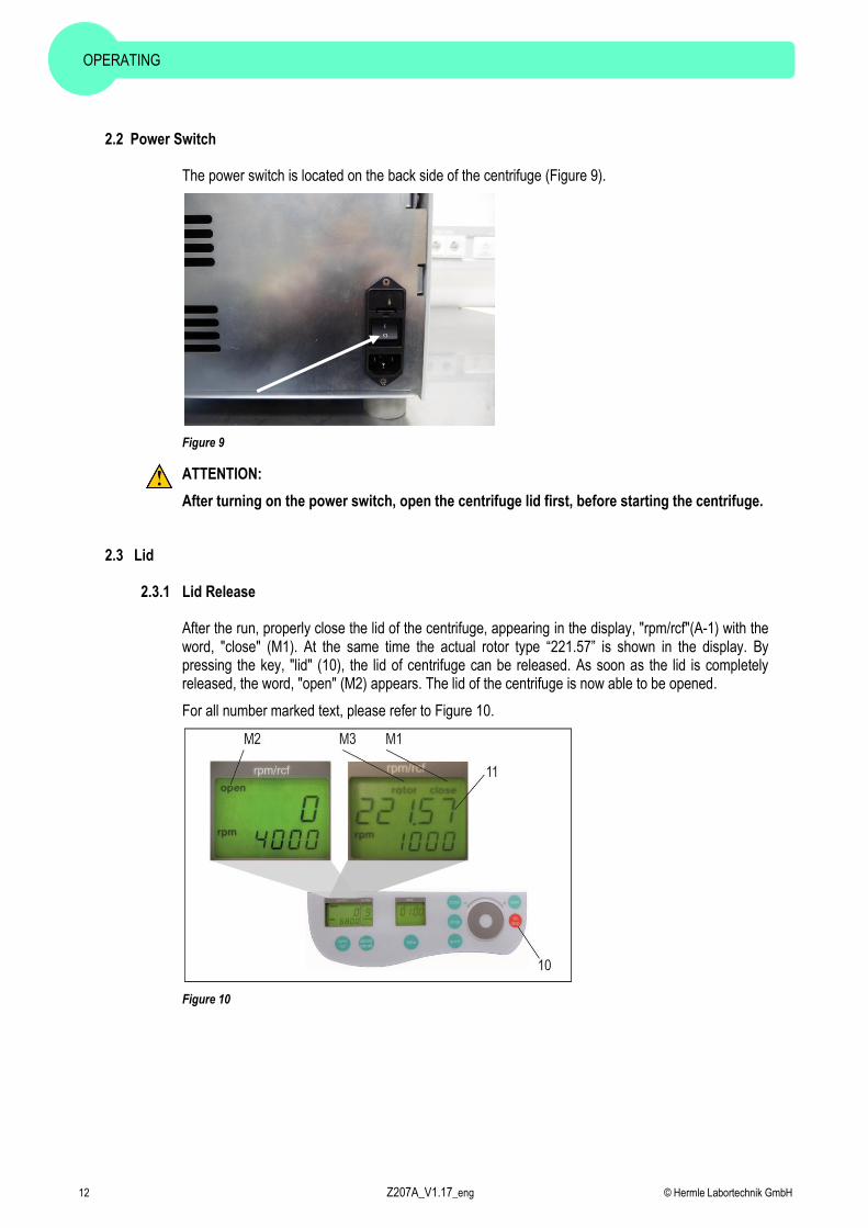
2.2 Power Switch
The power switch is located on the back side of the centrifuge (Figure 9).
Figure 9
ATTENTION:
After turning on the power switch, open the centrifuge lid first, before starting the centrifuge.
2.3 Lid
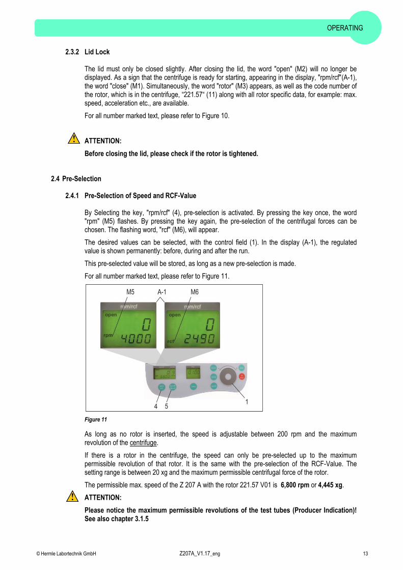
2.3.1 Lid Release
After the run, properly close the lid of the centrifuge, appearing in the display, "rpm/rcf"(A-1) with the word, "close" (M1). At the same time the actual rotor type “221.57” is shown in the display. By pressing the key, "lid" (10), the lid of centrifuge can be released. As soon as the lid is completely released, the word, "open" (M2) appears. The lid of the centrifuge is now able to be opened.
For all number marked text, please refer to Figure 10.
Figure 10
OPERATING
© Hermle Labortechnik GmbH Z207A_V1.17_eng 13
2.3.2 Lid Lock
The lid must only be closed slightly. After closing the lid, the word "open" (M2) will no longer be displayed. As a sign that the centrifuge is ready for starting, appearing in the display, "rpm/rcf"(A-1), the word "close" (M1). Simultaneously, the word "rotor" (M3) appears, as well as the code number of the rotor, which is in the centrifuge, “221.57“ (11) along with all rotor specific data, for example: max. speed, acceleration etc., are available.
For all number marked text, please refer to Figure 10.
ATTENTION:
Before closing the lid, please check if the rotor is tightened.
2.4 Pre-Selection
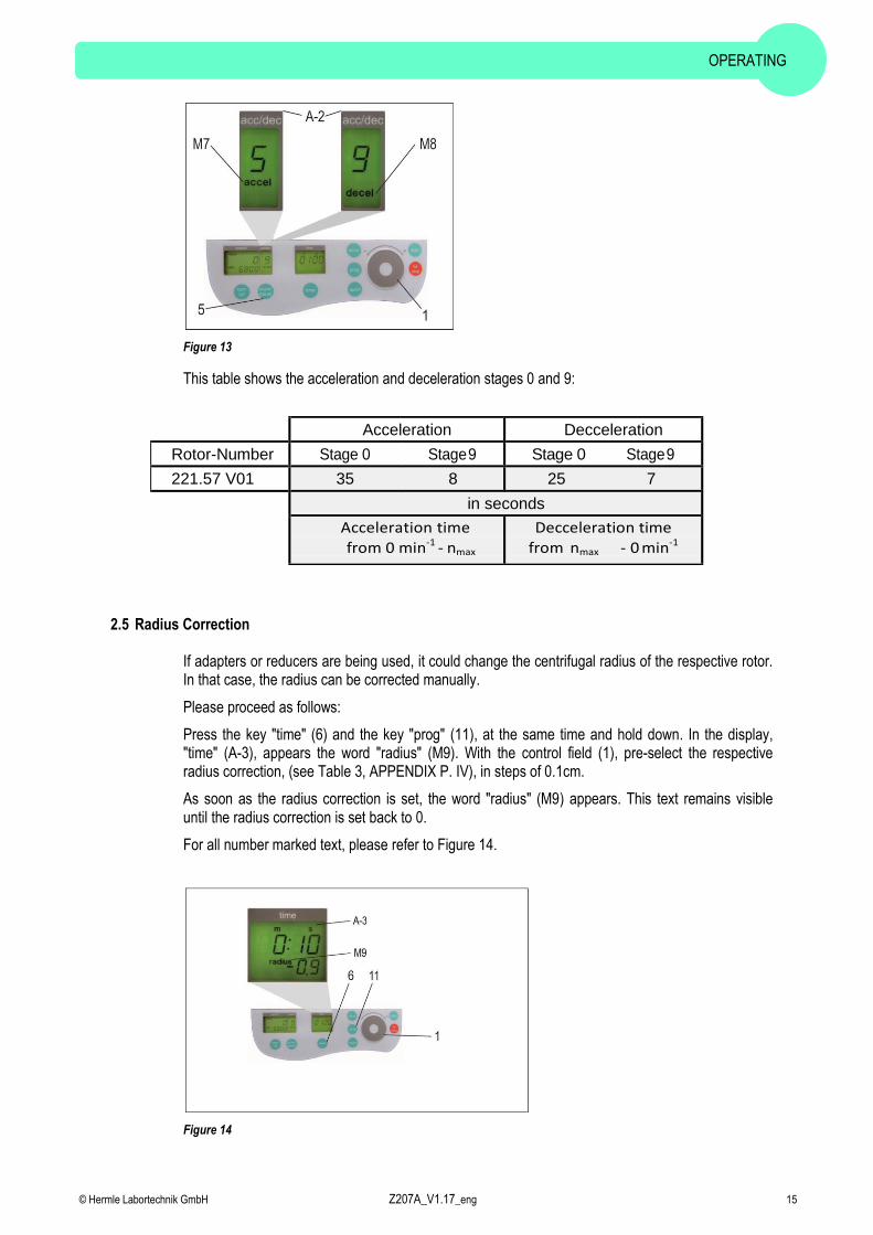
2.4.1 Pre-Selection of Speed and RCF-Value
By Selecting the key, "rpm/rcf" (4), pre-selection is activated. By pressing the key once, the word "rpm" (M5) flashes. By pressing the key again, the pre-selection of the centrifugal forces can be chosen. The flashing word, "rcf" (M6), will appear.
The desired values can be selected, with the control field (1). In the display (A-1), the regulated value is shown permanently: before, during and after the run.
This pre-selected value will be stored, as long as a new pre-selection is made.
For all number marked text, please refer to Figure 11.
Figure 11
As long as no rotor is inserted, the speed is adjustable between 200 rpm and the maximum revolution of the centrifuge.
If there is a rotor in the centrifuge, the speed can only be pre-selected up to the maximum permissible revolution of that rotor. It is the same with the pre-selection of the RCF-Value. The setting range is between 20 xg and the maximum permissible centrifugal force of the rotor.
The permissible max. speed of the Z 207 A with the rotor 221.57 V01 is 6,800 rpm or 4,445 xg.
ATTENTION:
Please notice the maximum permissible revolutions of the test tubes (Producer Indication)! See also chapter 3.1.5

OPERATING
14 Z207A_V1.17_eng © Hermle Labortechnik GmbH
2.4.2 Pre-Selection of Running Time
The running time can be pre-selected in 3 different ranges: from 10 seconds up to 99 hours 59 minutes.
1. Range from: 10 seconds up to 59 minutes 50 seconds, in steps of 10 seconds
2. Range from: 1 hour up to 99 hours 59 minutes, in steps of 1 minutes
3. Range: Continuous Run "cont", can be interrupted by the key, "stop" (10).
-The running time can be pre-selected, with the lid opened or closed. -To activate the setting of the running time, press the key "time" (6). -In the display, "time" (A-3) flashes the indication: "m : s" or "h : m", depending on the previous setting.
To set the desired value, use the control field (1). After exceeding 59 min 50 sec, the indication changes automatically to, "h : m". After exceeding 99 hours 59 min, the word "cont" appears in the display, "time" (A-3).
The continuous run can only be interrupted by pressing the key, "stop" (10). The time counts down, as soon as the set speed is reached.
For all number marked text, please refer to Figure 12.
Figure 12
2.4.3 Pre-Selection of Brake Intensity and Acceleration
Selecting the key, "accel/decel" (5), this function is activated.
By pressing the key once, the word "accel" (M7) flashes, in the display "accel/decel" (A-2). The desired acceleration can be pre-selected, with the control field (1). The value 0 is equivalent to the lowest acceleration and the value 9 is equivalent to the highest acceleration.
By pressing the key "accel/decel" (5) twice, in the display "accel/decel" (A-2), indicates the word "decel" (M8). Now the desired brake intensity can be pre-selected, with the control field (1). The value 9 is equivalent to the shortest possible brake time and the value 0 to longest possible brake time.
For all number marked text, please refer to Figure 13.
OPERATING
© Hermle Labortechnik GmbH Z207A_V1.17_eng 15
Figure 13
This table shows the acceleration and deceleration stages 0 and 9:
2.5 Radius Correction
If adapters or reducers are being used, it could change the centrifugal radius of the respective rotor. In that case, the radius can be corrected manually.
Please proceed as follows:
Press the key "time" (6) and the key "prog" (11), at the same time and hold down. In the display, "time" (A-3), appears the word "radius" (M9). With the control field (1), pre-select the respective radius correction, (see Table 3, APPENDIX P. IV), in steps of 0.1cm.
As soon as the radius correction is set, the word "radius" (M9) appears. This text remains visible until the radius correction is set back to 0.
For all number marked text, please refer to Figure 14.
Figure 14
Acceleration Decceleration
Rotor-Number Stage 0 Stage 9 Stage 0 Stage 9
221.57 V01 35 8 25 7
in seconds
Acceleration time
from 0 min-1 - nmax
Decceleration time
from nmax - 0 min-1

OPERATING
16 Z207A_V1.17_eng © Hermle Labortechnik GmbH
2.6 Program
2.6.1 Storage of Programs
The program stores up to 99 runs, with all relevant parameters, including the used rotors. Any free program number is available and can be retrieved.
Put the rotor into the centrifuge. By pressing the key, "prog" (11), in the display "time" (A-3) appears the word "program", (see Figure 15). With the control field (1), choose the desired program number.
If a program number is already occupied, in the display "rpm/rcf" (A-1), the words "rotor" (M3) and "221.57" (M4) will appear, (see Figure 15). Free program numbers will appear as 0.
Figure 15
Close the lid of the centrifuge, now proceed as described above, to set all important run parameters. If the lid isn´t closed, when storing the program in the display "rpm/rcf" (A-1), flashes alternately the word "FirSt" and "CLOSE Lid" (see Figure 16). When starting the run without storing the program, in the display "rpm/rcf" (A-1), flashes alternately the word "First" and "PrESS StoreE", (see Figure 17).
Figure 16 Figure 17
For alteration of data, press the key "store" (12), for approx. 1 second. If the program is stored correctly, the word "StorE" appears in the display "rpm/rcf" (A-1). As a result, the word "program" (M10) disappears. As soon as the key "store" (12) is no longer displayed, the word "programm xx" (M10) reappears, (the xx stands for the chosen program place).
If all program numbers are occupied, take an old number that is not needed any longer and replace it with the new parameters.
OPERATING
© Hermle Labortechnik GmbH Z207A_V1.17_eng 17
2.6.2 Recall of Stored Programs
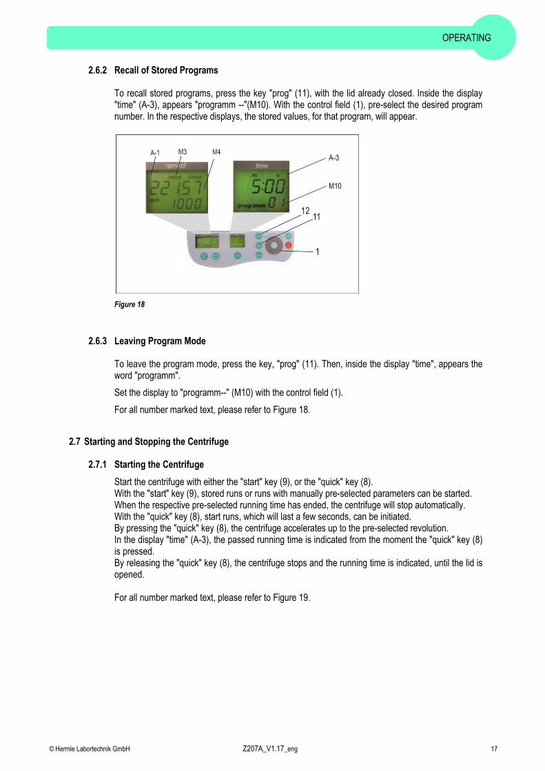
To recall stored programs, press the key "prog" (11), with the lid already closed. Inside the display "time" (A-3), appears "programm --"(M10). With the control field (1), pre-select the desired program number. In the respective displays, the stored values, for that program, will appear.
Figure 18
2.6.3 Leaving Program Mode
To leave the program mode, press the key, "prog" (11). Then, inside the display "time", appears the word "programm".
Set the display to "programm--" (M10) with the control field (1).
For all number marked text, please refer to Figure 18.
2.7 Starting and Stopping the Centrifuge
2.7.1 Starting the Centrifuge
Start the centrifuge with either the "start" key (9), or the "quick" key (8). With the "start" key (9), stored runs or runs with manually pre-selected parameters can be started. When the respective pre-selected running time has ended, the centrifuge will stop automatically. With the "quick" key (8), start runs, which will last a few seconds, can be initiated. By pressing the "quick" key (8), the centrifuge accelerates up to the pre-selected revolution. In the display "time" (A-3), the passed running time is indicated from the moment the "quick" key (8) is pressed. By releasing the "quick" key (8), the centrifuge stops and the running time is indicated, until the lid is opened. For all number marked text, please refer to Figure 19.

OPERATING
18 Z207A_V1.17_eng © Hermle Labortechnik GmbH
Figure 19
2.7.2 The “STOP” KEY
With the "stop" key (10), the run time can be interrupted, at any time, (see Figure 20). After pressing the key, the centrifuge decelerates with the respective pre-selected intensity, down to a standstill.
Figure 20
2.8 Imbalance Detection
In case the rotor is not equally loaded, the drive will turn off, during acceleration. The rotor decelerates to a standstill.
When in the display "time" (A-3), the word "error" (M11) along with the number "01" appears, the weight difference of the samples are too large. Weigh out the samples exactly!
Load the rotor as described in Chapters: 2.1.2 and 2.1.3.
When inside the display "time" (A-3), the word "error" along with the number "02" appears, (see Figure 21). Potential reason for this error can be: The imbalance switch is defective.

OPERATING
© Hermle Labortechnik GmbH Z207A_V1.17_eng 19
Figure 21

MAINTENANCE
20 Z207A_V1.17_eng © Hermle Labortechnik GmbH
3. MAINTENANCE
3.1 Maintenance and Cleaning
3.1.1 General
Maintenance:
Maintenance of the centrifuge is dependent on prolonging the life of the rotor, the rotor chamber and the rotor accessories.
Don´t use acid detergents and/or burnished polish.
Breakage of rotors can be caused by the slightest damages.
In case of metallic rotor parts or the motor shaft becoming in touch with corrosive substances, the affected area must be cleaned, thoroughly.
Corrosive substances, such as, must be avoided: alkalis, alkaline soap solutions, alkaline amines, concentrated acids, solutions containing heavy metals, water-free chlorinated solvents, saline solutions, e.g. salt water, phenol, halogenated hydrocarbons.
Maintenance – Unit, Rotor, Accessories:
- Turn the device off and disconnect from the power supply, before beginning any cleaning or
disinfecting. Do not pour liquids into the housing interior.
- Spray disinfectant on the device. - Thorough cleaning not only has its purpose in hygiene, but also in avoiding pollution based
corrosion. - In order to avoid damaging anodized parts, such as rotors, reduction plates etc.; only pH-neutral
Detergents, with a pH-value of 6-8, may be used for cleaning. Alkaline cleaning agents must not be used, (pH-value > 8).
- After cleaning, please ensure all parts are dried thoroughly, either by hand or in a hot-air cabinet (Max. Temperature + 50°C/122°F).
- It is necessary to coat anodized aluminium parts with anti-corrosion oil regularly, in order to increase their life-span and reduce corrosion predisposition.
- Due to humidity or not hermetically sealed samples, condensation may form. The condensation
has to be removed from the rotor chamber, with a soft cloth regularly.
The maintenance procedure has to be repeated every 10 to 15 runs, but at least once at week!
- Connect the unit to the power supply, after the equipment is completely dry.
- Do not implement disinfection with UV-, beta- and gamma-rays or other high energy radiation.

MAINTENANCE
© Hermle Labortechnik GmbH Z207A_V1.17_eng 21
3.1.2 Cleaning and Disinfection of the Unit
1. Open the lid, before turning off the unit. Disconnect from the power supply.
2. Open the rotor nut, by turning the rotor key counter-clockwise.
3. Remove the rotor.
4. For cleaning and disinfection of the unit and the rotor chamber, use the above mentioned
cleaner.
5. Clean all accessible areas of the device and its accessories, including the power cord, with a
damp cloth.
6. Wash the rubber seals and rotor chamber thoroughly, with water.
7. Rub the dry rubber seals with glycerol or talc, to prevent these from becoming brittle. Other
components of the unit, e.g. the lid lock, motor shaft and rotor, should not be greased.
8. Dry the motor shaft with a soft, dry and lint-free cloth.
9. Examine the unit and accessories for damage.
Remove adherent dust, at least every 6 months, from the ventilation slots in the centrifuge, by using a soft brush.
*Before doing so, please switch off the unit and disconnect from the power supply.
3.1.3 Cleaning and Disinfection of the Rotor
1. Clean and disinfect: the rotors and adapters, with the cleaner previously mentioned above.
2. Use a bottle brush to clean and disinfect the rotor bores.
3. Rinse the rotor and adapter, with clear water. Particularly, the drillings of the angle rotors.
4. When drying the rotor and adapter, set on a towel. Place the angle rotor, with bores down, to
dry.
5. Dry the rotor cone with a soft, dry and lint-free cloth, check for damage. Do not grease the rotor
cone.
6. Put the dry rotor back on the motor shaft.
7. Fix the rotor by turning the rotor nut clockwise.
3.1.4 Disinfection of PP-Rotors
Autoclaving
During autoclaving, it´s quite possible that plastic parts, i.g. rotor, can become deformed!
The recommended time for autoclaving: 15 – 20 min at 121°C/250°F, (1 bar)
ATTENTION: The sterilization time of 20 min. must not be exceeded. Continuous sterilization will cause reduction in the mechanical resistance, of the plastic material.
Before autoclaving the PP-rotor and adapter, thoroughly clean to avoid the burning of dirty residue.
Please disregard any consequences of chemical residues to plastic materials, at ambient temperatures. At high temperatures, autoclaving residue may corrode and destroy the plastic. The objects must be thoroughly washed with distilled water, after the cleaning, but before the autoclaving. Residues of any cleaning liquids, may cause fissures, whitening and stains.

MAINTENANCE
22 Z207A_V1.17_eng © Hermle Labortechnik GmbH
Gas Sterilization
Adapters, bottles and rotors may be gas sterilized, with Ethylenoxyd. According to the duration of the application, allow items to properly air out, after the sterilization and before usage.
ATTENTION: The temperature may rise during the sterilization; rotors, adapters and bottles should not be fully closed, keep completely unscrewed.
Chemical Sterilization
Bottles, adapters and rotors may be treated, with the usual liquid disinfectants.
ATTENTION: Before applying any other, Cleaning Resp. Decontamination Method, other than what was recommended by the manufacturer, contact the manufacturer to ensure that it will not damage the unit or the rotor.
3.1.5 Glass Breakage
With high g-values, the rate of glass tube breakage increases. Glass splinters have to be removed immediately from rotor, adapters and the rotor chamber itself. Fine glass splinters will scratch and therefore damage the protective surface coating of a rotor. If glass splinters remain in the rotor chamber, fine metal dust will build up, due to air circulation. This very fine, black metal dust will severely pollute the rotor chamber, the rotor and the samples.
If necessary, replace the adapters, tubes and accessories, to avoid further damage. Check the rotor bores regularly, for residue and damage.
ATTENTION: Please check the relevant specifications of the tubes centrifuges with the manufacturer!
3.2 Lifetime of Rotors and Accessories
Rotor and adapter have an operating time of max. 3 years from first use.
Conditions for the Operating Time:
Proper use, damage-free condition, recommended care.

TROUBLE SHOOTING
© Hermle Labortechnik GmbH Z207A_V1.17_eng 23
4. TROUBLE SHOOTING
4.1 Error Message: Problem / Solution
The error messages are listed to help localize possible errors faster.
The possible error referred to in this chapter may not always be the case, as they are only theoretically occurring errors and solutions.
Always keep us informed about any kind of error occurring, which is not listed in this chapter. With this information provided, we are able to improve and complete this operation manual.
Many thanks in advance for your support.
HERMLE Labortechnik GmbH
4.2 Survey of Possible Error Messages and Solutions
4.2.1 Lid Release during Power Failure (Emergency Lid Release)
In case of power failure or malfunction, the lid of the centrifuge can be opened manually, in order to protect samples.
Please proceed as follows:
• Switch off the centrifuge and unplug the power cord, wait until the rotor has come to a standstill (this may take several minutes)
• On the left hand, bottom side of the centrifuge housing, there is a plastic stopper (see Figure 22).
Remove this stopper. Fastened to it, is a string which is connected to the lid lock.. • Pull the string slightly and the lid will open. • Open the lid of the centrifuge.
• Switch the centrifuge on again, to proceed with regular function.
Figure 22

TROUBLE SHOOTING
24 Z207A_V1.17_eng © Hermle Labortechnik GmbH
4.2.2 Description of the Error Message System
The error message, "error" (M11), is shown in the "time" (A-3) display, (see Figure 23). For more detailed information, refer to Table 2: "Error Messages", (see Appendix P. IV).
Figure 23

RECEIPT OF CENTRIFUGES TO REPAIR
© Hermle Labortechnik GmbH Z207A_V1.17_eng 25
5. RECEIPT OF CENTRIFUGES TO REPAIR
Health risk from contaminated equipment, rotors and accessories
In case of returning the centrifuge for repairing to the manufacturer, please know the following:
The centrifuge must be decontaminated and cleaned, before shipment to Hermle Labortechnik, for the protection of persons, environment and material.
Decontamination certificate at goods return delivery (see APPENDIX P. V)
We reserve the right to accept contaminated centrifuges.
Furthermore, all costs that may have occurred during the cleaning and disinfection of the units will go to the debit of the customer’s account.
TRANSPORT, STORAGE AND DISPOSAL
26 Z207A_V1.17_eng © Hermle Labortechnik GmbH
6. TRANSPORT, STORAGE AND DISPOSAL
6.1 Transport
Before transporting, take out the rotor. Only transport the unit in its' original packaging. Use a transport aid, for transporting over longer distances, to fix the motor shaft.
Air Temperature Rel. Humidity Air Pressure
General Transportation -25 to 60 °C 10 to 75 % 30 to 106 kPa
6.2 Storage
During storage of the centrifuge, the following environmental conditions must be observed:
Air Temperature Rel. Humidity Air Pressure
Transport Packaging -25 to 55 °C 10 to 75 % 70 to 106 kPa
6.3 Disposal
The disposal of the electrical devices is regulated within the European Community, by national regulations, based on EU Directive 2002/96/EC pertaining to waste electrical and electronic equipment (WEEE).
In accordance with this, any devices delivered after 08/13/2005 on a business-to-business basis, including the product, may no longer be disposed of, as a household waste. To document this, the devices have been marked with the following identification:
Because disposal regulations may differ from one country to another, within the EU, please contact your supplier, if necessary.
RoHS II Compliance
HERMLE Labortechnik GmbH, Siemensstraße 25, 78564 Wehingen, hereby declares and certifies that all components manufactured are RoHS II compliant, according to the definition and restrictions given by the European Parliament Directive 2011/65/EC. This restricts the use of certain hazardous substances in electrical and electronic equipmen

TRANSPORT, STORAGE AND DISPOSAL
© Hermle Labortechnik GmbH Z207A_V1.17_eng 27

TRANSPORT, STORAGE AND DISPOSAL
28 Z207A_V1.17_eng © Hermle Labortechnik GmbH

APPENDIX
© Hermle Labortechnik GmbH Z207A_V1.17_eng I
7. APPENDIX
EG – Conformity Declaration ............................................................................................... II
Table 1: Technical Data...................................................................................................... III
Table 2: Error Messages .....................................................................................................IV
Table 3: Radius Correction .................................................................................................IV
Table 4: Symbols- / Abbreviations .....................................................................................IV
Redemption Form: Decontamination Certificate .............................................................. V

APPENDIX
II Z207A_V1.17_eng © Hermle Labortechnik GmbH
EG – Conformity Declaration
EG Konformitätserklärung
EC Conformity Declaration
Hermle Labortechnik GmbH - Siemensstr. 25 - D-78564 Wehingen – Germany
Das bezeichnete Produkt entspricht den einschlägigen grundlegenden Anforderungen der aufgeführten EG-Richtlinien und Normen. Bei einer nicht mit uns abgestimmten Änderung des Produktes oder einer nicht bestimmungsgemäßen Anwendung
verliert diese Erklärung ihre Gültigkeit.
The Product named below fulfills the relevant fundamental requirements of the EC directives and standards
listed. In the case of unauthorized modifications to the product or an unintended use this declaration becomes invalid.
Produkttyp Product Type
Laborzentrifugen mit Zubehör nach „IVD (sonstige Produkte)” Laboratory centrifuge with accessories to “IVD (other device)”
Typenbezeichnung Typ Designation
Z 206 A; Z 207 A; Z 216 M; Z 306; Z 326; Z 366; Z 446; Z 216 MK; Z 32 HK; Z 326 K; Z 366 K; Z 36 HK; Z 446 K
Einschlägige EG-Richtlinien / Normen Relevant EC Directives / Standards
98/79/EG (Anhang/Annex III); 2014/35/EU; 2014/30/EU, RoHS II 2011/65/EG, DIN EN 61010-1: 2011-07; EN 61010-2-020: 2007-03; EN 61010-2-101: 2002
DIN EN ISO 14971: 2013-04; DIN EN ISO 13485: 2012-11
Wehingen, 22.09.2016
(gültig bis/valid until 21.12.2018) Alexander Hermle Geschäftsführer,Managing Director

APPENDIX
© Hermle Labortechnik GmbH Z207A_V1.17_eng III
Table 1: Technical Data
Manufacturer
HERMLE Labortechnik GmbH, 78564 Wehingen
Type Z 207 A
Dimensions
Width 28 cm
Depth 35 cm
Height 24 cm
Weight without rotor 8,0 kg
Max. Speed 6,800 min-1
Max. Volume 8 x 15 ml
Max. RCF 4,445 x g
Allowable Density 1.2 kg/dm3
Allowable Kinetic Energy 845 Nm
Mains Power Connection AC 100-230 V / 50-60 Hz 1 ph
Voltage Fluctuation ± 10 %
Current Consumption 0.8 – 0.4 A
Power Consumption 50 W
Radio Interference IEC 61326-1
Audit Requirement (BGR 500) no
Ambient Conditions (EN/IEC 61010-1)
Environment For Indoor Use Only
High Use up to an altitude of 2000 m above MSL
Ambient Temperature 2°C up to 35 °C
Max. Relative Humidity Max. relative humidity 80 % for temperatures up to 31°C,
decreasing linearly to 50% relative humidity up to 35°C
Overvoltage Category (IEC 60364-4-443) II
Degree of Contamination 2
Class of Protection I Class of Protection (DIN EN 60529) IP 20
Not suitable for use in hazardous environments
EMV
Interference Emission, Noise Immunity
EN /
IEC
61326-1
Category B
FCC Class B
Noise Level (depending on the rotor) 60 dB(A)
Write from Operator
Inventory-No.:
Monitoring-No.:
Environment:
Maintenance Contract:
HERMLE Labortechnik GmbH or dealer service office
Siemensstraße 25
Responsible Service Office 78564 Wehingen
Tel.: (49)7426 / 96 22-17
Fax: (49)7426 / 96 22-49
Responsible Dealer

APPENDIX
IV Z207A_V1.17_eng © Hermle Labortechnik GmbH
Table 2: Error Messages
Error-No. No.Nr.:
Describtion
1 Imbalance
2 Imbalance sensor is defective
14 Problem with speed sensor
15 Standstill monitoring defective
33 Open lid while motor is running
34 Lid contact defective
43 Undervoltage frequency converter
44 Overvoltage frequency converter
47 Error current detection
55 Overspeed
80 Memory Error intern EEPROM
Table 3: Radius Correction
Rotor No. Adapter
Order-No. Radius (cm) Correction
(cm)
Angle Rotor
8.6 0
221.57
701.011 8.3 -0.3
701.012 7.0 -1.6
701.015 5.6 -3.0
Table 4: Symbols- / Abbreviations
Symbol / Abbreviations
Unit
Describtion
n (=rpm) [min
-1] revolutions per minute
RZB(=rcf) [x g] relative centrifugal force
PP - Polypropylen
PC - Polycarbonat

APPENDIX
© Hermle Labortechnik GmbH Z207A_V1.17_eng V
Redemption Form: Decontamination Certificate
Enclose all returned shipping items and modules necessary!
The completely full declaration about the decontamination is prerequisite for the assumption and further processing of the return. If no corresponding explanation is enclosed, we carry out decontamination with costs at your expense.
Surname; Last name: _____________________________________
Organization / Company: _____________________________________
Street: _____________________________________
ZIP CODE: _____________ place: __________________
Telephone: _____________ fax: ____________________
E-Mail: _____________________________________
Pos. Quantity Decontaminated Object Serial No. Description / Comment
1
2
3
4
Are the parts listed above in touch with the following substances?
Health endangering watery solutions, buffers, acids, alkalis:……….............. ..... Yes No
Potentially infectious agents: ………………………………………………………... Yes No
Organic reagents and solvent: ………………………………...……..................... Yes No
Radioactive substances: ………………………………………..… α.. β.. γ.. Yes No
Health endangering proteins: …………………………………….……………......... Yes No
DNA: ………………………………………………………………………………….…. Yes No
Have these substances reached the equipment/assembly? ………………………….. Yes No
If so, which ones: ________________________________________________________________
Description of the measures for the decontamination of the listed parts:
I confirm the proper decontamination:
Company/Dept ._____________ Place and Date: ______________________________
Signature of the authorized person: ________________________________________
Decontamination Certificate of Googs Returned Upon Delivery
Ple
ase
fill o
ut in
blo
ck
capi
tals
!

Z207A_V1.17_eng © Hermle Labortechnik GmbH

© Hermle Labortechnik GmbH Z207A_V1.17_eng
NOTES

Z207A_V1.17_eng © Hermle Labortechnik GmbH
HERMLE Labortechnik GmbH
Siemensstraße 25
78564 Wehingen
Tel: 0 74 26-96 22-17
Fax: 0 74 26-96 22-49
Email: [email protected]
Internet: http://www.hermle-labortechnik.de
Technical rights reserved
©HERMLE Labortechnik GmbH 2017