operating manual dc330/500 - converting made easy · gm · converting unit 9 3. touch panel the...
TRANSCRIPT

· GM CONVERTING UNIT ·
OPERATING MANUAL
DC330/500
Grafisk Maskinfabrik A/S Bregnerødvej 92, DK-3460 Birkerød · Denmark · Phone: +45 4581 2300
Internet: www.gm.dk · e-mail: [email protected] ·Fax:+45 4581 9956

GM · CONVERTING UNIT
2
Rev 1.26 (V6 machines) 09/01-2014
GM · CONVERTING UNIT
3
EU Declaration of Conformity
We Manufacturer:
Grafisk Maskinfabrik A/S Bregnerødvej 92
DK-3460 Birkerød Denmark Telephone: + 45 45 81 23 00 Fax: + 45 45 81 99 56
Herewith declare that the product
Equipment: D500 basic unit Model number: DC5V8-BX
Serial number / production year: 113215 / 2013
Is in compliance with the relevant requirements in the following directives:
Machinery Directive 2006/42/EC
EMC Directive 2004/108/EC
Harmonized specifications applied:
EN 60204-1 Safety of machinery. Electrical equipment of machinery. EN 13849 Safety of machinery -- Safety-related parts of control systems EN 12100 Safety of machinery
Person authorised to compile and hold the technical documentation: Bjarne Nielsen Managing Director Uffe Nielsen (Mr.) Grafisk Maskinfabrik A/S 17/12- 2013 Birkerød Uffe Nielsen . Date Signature

GM · CONVERTING UNIT
4
GM · CONVERTING UNIT
5
EU Declaration of Conformity ..................................................................................................................... 3
1. Safety instructions ............................................................................................................................... 7
2. Control panel ........................................................................................................................................ 8
3. Touch panel .......................................................................................................................................... 9
4. The main screen ................................................................................................................................. 10
4.1. Web entry ............................................................................................................................................ 11
4.2. The varnish station ............................................................................................................................ 12
4.3. The spot varnish option ..................................................................................................................... 12
4.4. The laminating station....................................................................................................................... 12
4.5. The UV lamp ...................................................................................................................................... 13
4.6. The die-cutting station ....................................................................................................................... 13
4.7. Waste rewinder .................................................................................................................................. 14
4.8. V-knifes and Slitting knifes .............................................................................................................. 14
4.9. Rewinding ........................................................................................................................................... 15
5. Menu buttons ..................................................................................................................................... 16
5.1. Parameters .......................................................................................................................................... 18
5.2. Die-cut parameters ............................................................................................................................ 20
5.3. Speed control ...................................................................................................................................... 23
5.4. Web tension and scale print adjustments ....................................................................................... 25
6. Unwinder as rewinder ...................................................................................................................... 26
7. Alarms and messages ........................................................................................................................ 27
8. Language and units setup ................................................................................................................. 31
9. Special parameters ............................................................................................................................ 32
10. Registration accuracy ....................................................................................................................... 33
11. Markreader SUNX LX series .......................................................................................................... 34
12. Distortion and dispro factor ............................................................................................................. 35
13. Varnish station – prevent dripping ................................................................................................. 37
14. Dust problems with V-knifes & damages to anvil roller. ............................................................ 38
15. Die cut station adjustment and alignment ..................................................................................... 38
16. Die cut bridge adjustment ................................................................................................................ 39
17. General information for GM diecut station .................................................................................. 40
18. Pneumatic air cylinders .................................................................................................................... 41
19. Varnish station ................................................................................................................................... 43
19.1. Technical data .................................................................................................................................... 43
19.2. Anilox roller types .............................................................................................................................. 45
GM · CONVERTING UNIT
6
19.3. Mounting of the anilox roller ........................................................................................................... 46
19.4. Mounting of the ink roller ................................................................................................................ 46
19.5. Mounting of side blades and doctor blade ..................................................................................... 47
19.6. Filling of ink ........................................................................................................................................ 48
19.7. Mounting of print cylinder ............................................................................................................... 48
19.8. Adjustment of impression ................................................................................................................. 49
19.9. Cross register ...................................................................................................................................... 50
19.10. Triangle adjustment of the flexo unit (Coarse adjustment) ........................................................ 51
19.11. Troubleshooting ................................................................................................................................. 52
20. Spot varnish guide. ............................................................................................................................ 53
20.1. Step by step guide .............................................................................................................................. 54
20.2. Trouble shooting ................................................................................................................................ 55
20.1. Pictures ................................................................................................................................................ 56
20.2. The parameter screen ........................................................................................................................ 57
20.3. The run screen .................................................................................................................................... 58
20.4. Print scaling ........................................................................................................................................ 59
21. Lamination (Tips and tricks) ........................................................................................................... 60
22. Operator Maintenance Chart .......................................................................................................... 60
23. Dimensions.......................................................................................................................................... 63
24. Spare parts and consumables .......................................................................................................... 64
25. Specification ....................................................................................................................................... 65
26. Cliché roller drawing ........................................................................................................................ 66
Specification die cylinder............................................................................................................................. 68
27. Installation guide ............................................................................................................................... 69
GM · CONVERTING UNIT
7
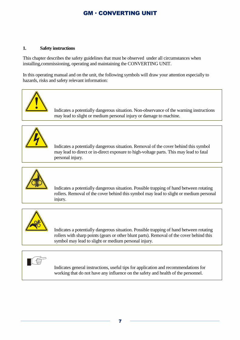
1. Safety instructions
This chapter describes the safety guidelines that must be observed under all circumstances when
installing,commissioning, operating and maintaining the CONVERTING UNIT.
In this operating manual and on the unit, the following symbols will draw your attention especially to
hazards, risks and safety relevant information:
Indicates a potentially dangerous situation. Non-observance of the warning instructions
may lead to slight or medium personal injury or damage to machine.
Indicates a potentially dangerous situation. Removal of the cover behind this symbol
may lead to direct or in-direct exposure to high-voltage parts. This may lead to fatal
personal injury.
Indicates a potentially dangerous situation. Possible trapping of hand between rotating
rollers. Removal of the cover behind this symbol may lead to slight or medium personal
injury.
Indicates a potentially dangerous situation. Possible trapping of hand between rotating
rollers with sharp points (gears or other blunt parts). Removal of the cover behind this
symbol may lead to slight or medium personal injury.
Indicates general instructions, useful tips for application and recommendations for
working that do not have any influence on the safety and health of the personnel.

GM · CONVERTING UNIT
8
2. Control panel
The control panel is fitted with a touch panel in the center, and separate sections on each side of the touch
panel. On the right side, the POWER button, Emergency Stop button, and the speed button is located. On
the left side, the five torque adjustment knobs are placed. The symbols indicate which spindle a torque
control knob is related to.
To power up, first check that the main switch is turned on, and the Emergency Stop button is released.
Press the POWER button. The touch panel will light up.
GM · CONVERTING UNIT
9
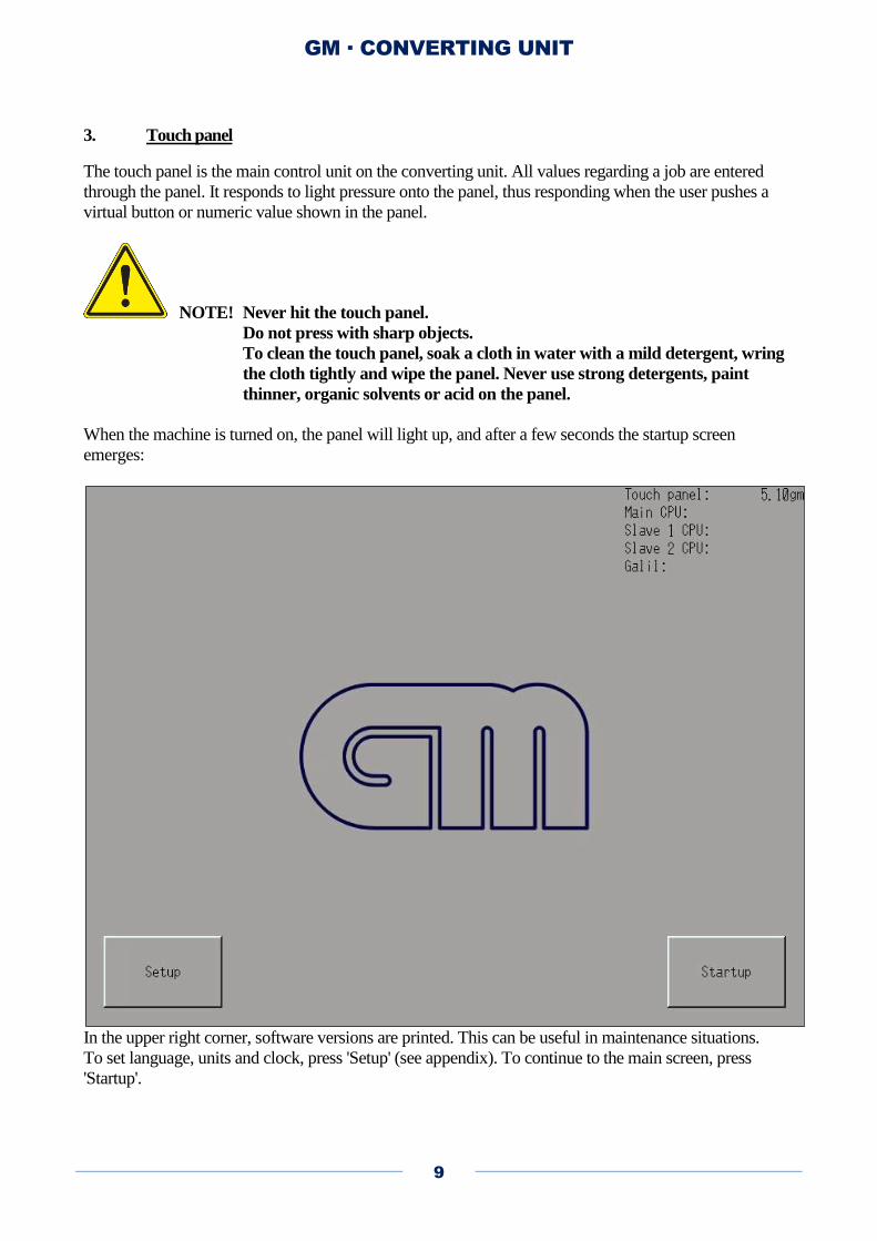
3. Touch panel
The touch panel is the main control unit on the converting unit. All values regarding a job are entered
through the panel. It responds to light pressure onto the panel, thus responding when the user pushes a
virtual button or numeric value shown in the panel.
NOTE! Never hit the touch panel.
Do not press with sharp objects.
To clean the touch panel, soak a cloth in water with a mild detergent, wring
the cloth tightly and wipe the panel. Never use strong detergents, paint
thinner, organic solvents or acid on the panel.
When the machine is turned on, the panel will light up, and after a few seconds the startup screen
emerges:
In the upper right corner, software versions are printed. This can be useful in maintenance situations.
To set language, units and clock, press 'Setup' (see appendix). To continue to the main screen, press
'Startup'.

GM · CONVERTING UNIT
10
4. The main screen
The majority of machine functions are operated on the main screen. A large graphic representation of the
machine is used for controlling
mandrel expansion
spindle modes
nip rollers
varnish roller
die-cut cylinder
UV lamp
slitter knives
A number of buttons, checkboxes and readouts are placed on the lower part of the screen.
The converting unit is equipped with six spindles with different functions:
Unwinder
Laminate unwinder
Laminate rewinder
Waste rewinder
Rewinder 1 (top)
Rewinder 2 (bottom)
GM · CONVERTING UNIT
11
Each spindle will change mode when the attached rotation mode button is pressed. Three of the
spindles can run in both directions (the two main rewinders and the laminate rewinder), and the rest can
run in only one direction. All spindles can be turned off.
When the center of a spindle is pressed, the air operated mandrel will expand (lock) or release.
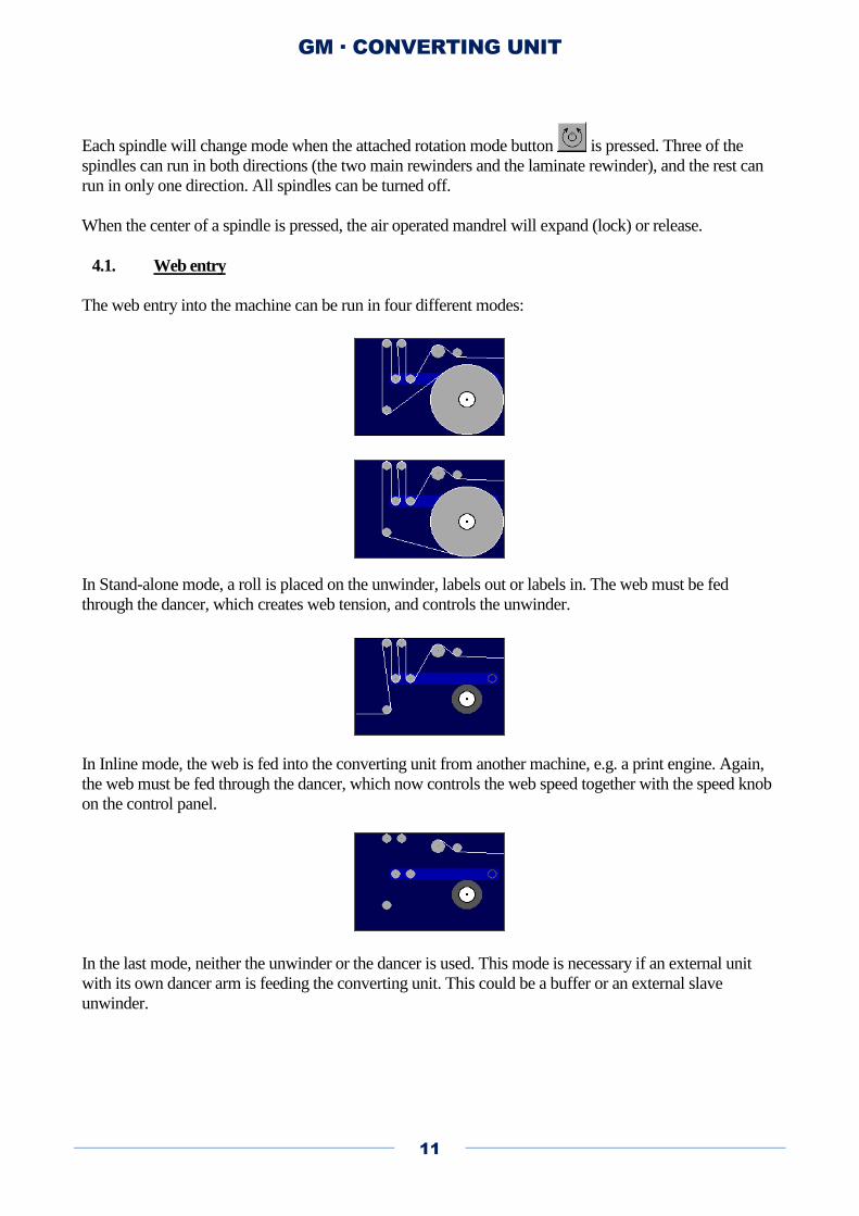
4.1. Web entry
The web entry into the machine can be run in four different modes:
In Stand-alone mode, a roll is placed on the unwinder, labels out or labels in. The web must be fed
through the dancer, which creates web tension, and controls the unwinder.
In Inline mode, the web is fed into the converting unit from another machine, e.g. a print engine. Again,
the web must be fed through the dancer, which now controls the web speed together with the speed knob
on the control panel.
In the last mode, neither the unwinder or the dancer is used. This mode is necessary if an external unit
with its own dancer arm is feeding the converting unit. This could be a buffer or an external slave
unwinder.
GM · CONVERTING UNIT
12
4.2. The varnish station
The varnish station contains the input nip roller and the varnish unit. Under normal operation, the input
nip must always be turned on, in order to create web tension. The nip roller is turned on and off by
pressing the small nip symbol in the lower part of the varnish station. Nips are coloured green when they
are off, and yellow when they are on.
The varnish roller can be engaged and released by pressing the roller symbol on the top of the varnish
station. It can also be turned on and off automatically when the web starts and stop. If the feature
'Automatic varnish roller' is turned on, the varnish roller will be engaged when the web moves, and
released when the web stops.
4.3. The spot varnish option
If the spot varnish option is installed, the varnish station can be used for full-rotation spot varnishing,
with varnish rollers from 10 to 19". In addition, a "slow run" feature is available, which is suitable for
varnish types which are not UV varnish. The spot varnish features are accessed in the Parameter menu.
4.4. The laminating station
The laminating station consists of two spindles, with the laminating nip and the UV lamp in between.
The laminate unwinder is above the UV lamp, and the laminate rewinder is below.
The laminate unwinder can run one way only, meaning that the outer surface of the foil will be the side
touching the web when laminating.
When laminating, the laminate nip roller will press the foil against the web. This nip roller can be
engaged only if the laminate unwinder is activated. This is to prevent the rubber roller from accidentally
being pressed into wet varnish or glue.
The pressure that the laminating nip applies onto the web can be adjusted with the air pressure regulator.
The pressure gauge will only display the pressure when the nip is engaged. If the regulator is turned all
the way to zero, the nip will not move when activated. A typical pressure setting is 1-2 bar.
The laminate unwinder and rewinder will not rotate when the laminate nip is off. This is to prevent the
laminate foil from rotating freely through the laminating station.
In the output end of the laminating station, the center nip is located. Under normal operation, the center
nip must always be turned on, in order to keep web tension through the die-cut station.
GM · CONVERTING UNIT
13
4.5. The UV lamp
The UV lamp is turned on and off be pressing the light bulb with the text 'UV'. When turned on, a few
seconds will pass before an attempt is made to ignite the lamp. When the UV lamp ignites, it goes in to a
heating sequence, which lasts about one minute. When the lamp is finally on, the lamp symbol turns
white.
If the lamp is hot when it is engaged, it will not turn on. The machine will let the lamp cool for a few
minutes, and will then try again automatically.
The UV lamp gets very hot, and proper cooling is necessary. Please check the cooling unit regularly.
When the lamp is lit, the cooling unit must be running.
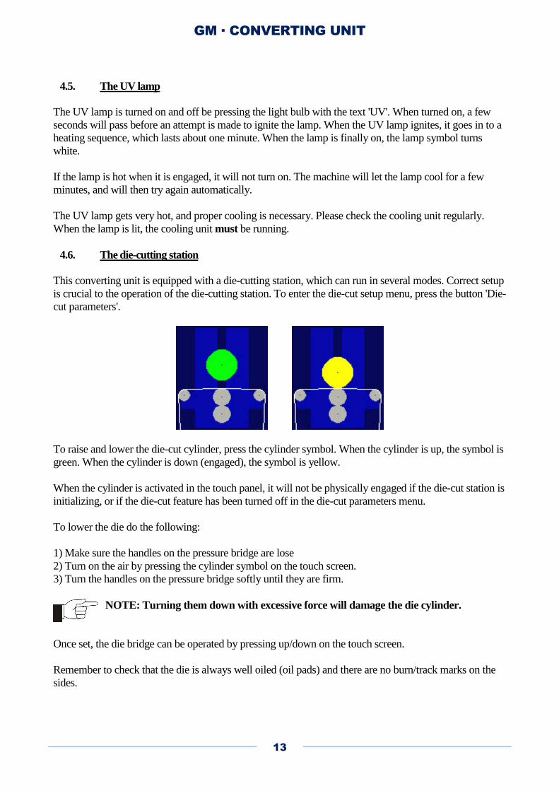
4.6. The die-cutting station
This converting unit is equipped with a die-cutting station, which can run in several modes. Correct setup
is crucial to the operation of the die-cutting station. To enter the die-cut setup menu, press the button 'Die-
cut parameters'.
To raise and lower the die-cut cylinder, press the cylinder symbol. When the cylinder is up, the symbol is
green. When the cylinder is down (engaged), the symbol is yellow.
When the cylinder is activated in the touch panel, it will not be physically engaged if the die-cut station is
initializing, or if the die-cut feature has been turned off in the die-cut parameters menu.
To lower the die do the following:
1) Make sure the handles on the pressure bridge are lose
2) Turn on the air by pressing the cylinder symbol on the touch screen.
3) Turn the handles on the pressure bridge softly until they are firm.
NOTE: Turning them down with excessive force will damage the die cylinder.
Once set, the die bridge can be operated by pressing up/down on the touch screen.
Remember to check that the die is always well oiled (oil pads) and there are no burn/track marks on the
sides.
GM · CONVERTING UNIT
14
4.7. Waste rewinder
The waste rewinder runs counter-clockwise only (glue inward). It is the only rewinder which can be
started and stopped while the machine is running. This is to make it easier to mount the waste grid.
4.8. V-knifes and Slitting knifes
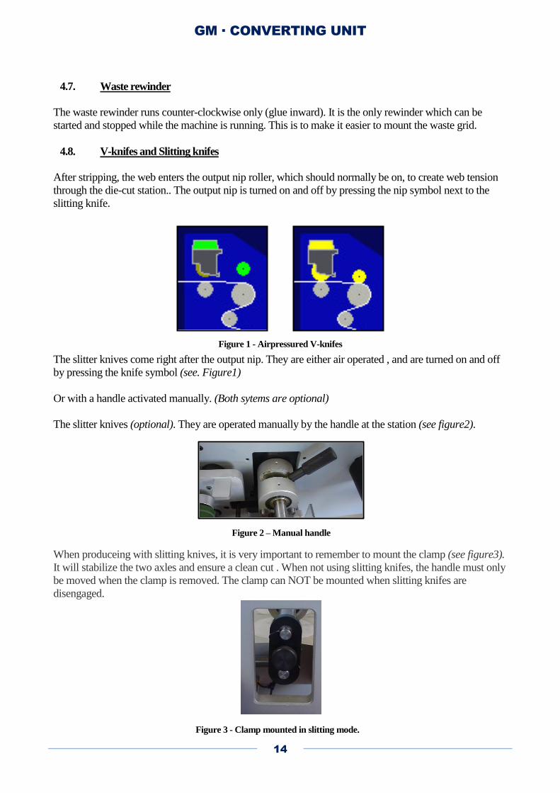
After stripping, the web enters the output nip roller, which should normally be on, to create web tension
through the die-cut station.. The output nip is turned on and off by pressing the nip symbol next to the
slitting knife.
The slitter knives come right after the output nip. They are either air operated , and are turned on and off
by pressing the knife symbol (see. Figure1)
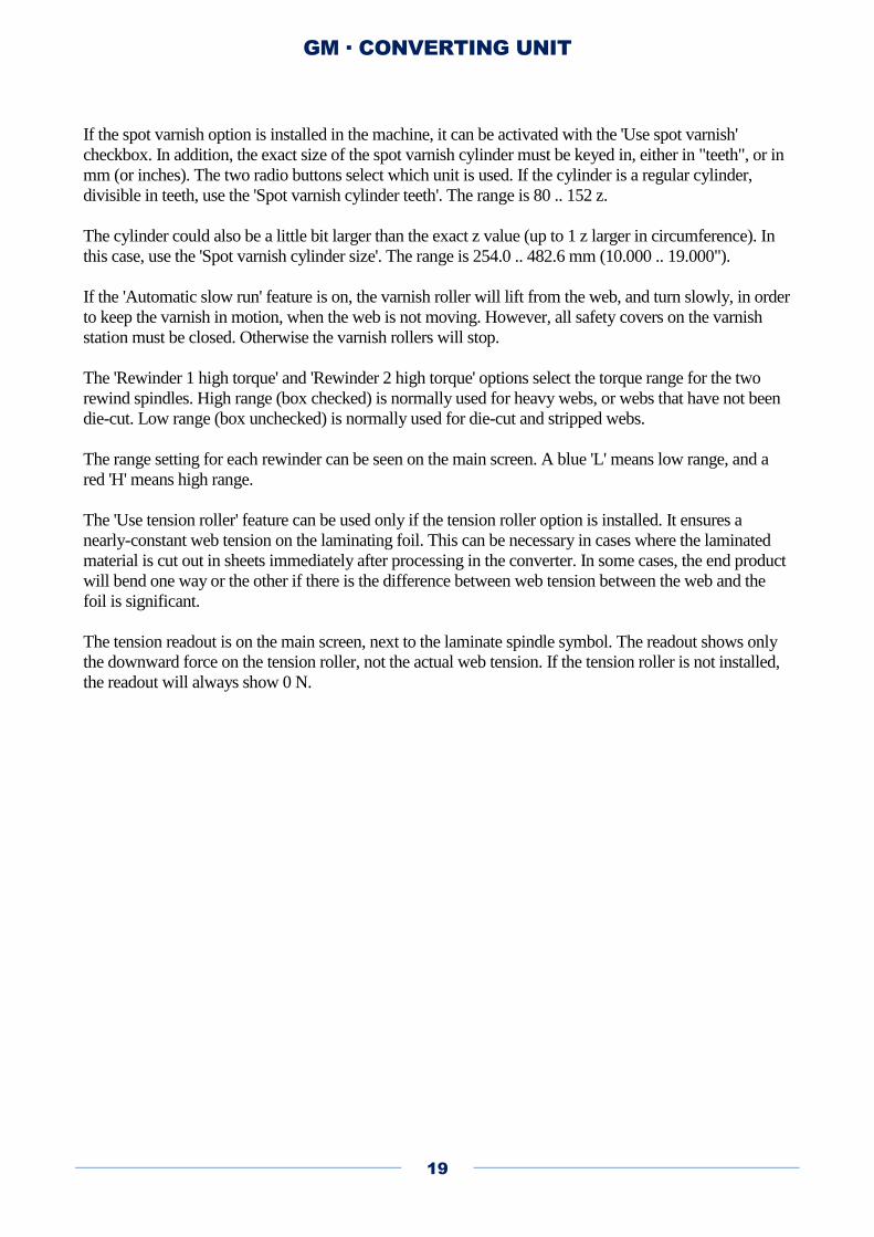
Or with a handle activated manually. (Both sytems are optional)
The slitter knives (optional). They are operated manually by the handle at the station (see figure2).
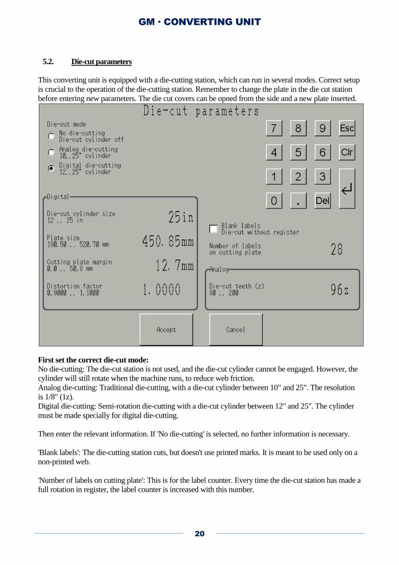
When produceing with slitting knives, it is very important to remember to mount the clamp (see figure3).
It will stabilize the two axles and ensure a clean cut . When not using slitting knifes, the handle must only
be moved when the clamp is removed. The clamp can NOT be mounted when slitting knifes are
disengaged.
Figure 1 - Airpressured V-knifes
Figure 2 – Manual handle
Figure 3 - Clamp mounted in slitting mode.

GM · CONVERTING UNIT
15
The slitting blades are running synchronised with web at a speed around 5% higher than the web. This
speed increase improves the cutting quality. When the safety cover is opened, the motor is turned off and
the blades are safe to move. Do never tighten the blades too hard, they just get harder to remove.
NOTE! Never try to open or close the slitter knife shafts with the knife clamp mounted
on the shafts. It will damage the balance in the shafts, and the knife clamp to lock the
shafts.
4.9. Rewinding
The two rewinders can run both ways, and can be individually turned off. As with all the other spindles,
the rotation mode is set with the rotation mode buttons, and the mandrel is engaged and released by
pressing the spindle.
The knife clamp

GM · CONVERTING UNIT
16
5. Menu buttons
Just below the machine drawing, you will find two white boxes. In the left box, two counters are placed:
A meter counter and a label counter. Each can be cleared by pressing the clear button [0]. Additionally,
the label counter can be turned on and off with the checkbox next to the counter. In the right box, info
messages, warnings and alarms will show up when the machine has something to report.
The 'Automatic stop at low unwinder diameter' feature makes the converting unit stop when the roll on
the unwinder spindle becomes smaller than a value entered in the Parameter menu.
The 'Automatic stop at label preset' feature makes the converting unit stop when the label counter reaches
or exceeds the preset value entered in the Parameter menu.
'UV min. power' is the minimum power that the UV lamp will deliver when the web is moving. When
web speed increases, the output power will also be increased. The value is altered by pressing the two
arrow-buttons to the left.
'UV power gradient' is the rate at which the power increases when web speed increases. The actual unit is
[W/(m/min)], i.e. with a web speed of 20 m/min, and a gradient of 200, the output power will be 4000 W.
The absolute maximum output power is 5000 W.

GM · CONVERTING UNIT
17
The green button in the center bottom part of the screen is the start button. Press this to start the machine.
Pressing the 'Use unwinder as rewinder' button will open the Unwinder as rewinder menu, which allows
the operator to rewind web directly onto the unwinder. In this mode, the speed of the unwinder spindle
(now rewinder) is controlled by the dancer.
Pressing the 'Die-cut parameters' button will enter the die-cut setup menu.
Pressing the 'Parameter menu' button will open the parameter menu, which contains values and features
not directly related to the die-cut station.
The 'Remote control window' button, or the button, opens a window with a remote controlling
feature for a digital press.
To stop the digital press, use the 'Remote Stop' button. The red lamp will light up briefly.
To make the remote control window disappear, press 'Close'.
To shut down the machine, press and hold 'Power off'. If the UV lamp is on, or has been on recently, the
machine will stay on (lamp off), and let the lamp cool before shutting down.

GM · CONVERTING UNIT
18
5.1. Parameters
The 'Automatic stop at low unwinder diameter' feature makes the converting unit stop when the roll on
the unwinder spindle becomes smaller than the value. The diameter range is 80 .. 200 mm (3.1 .. 7.9").
The 'Automatic stop at label preset' feature makes the converting unit stop when the label counter reaches
or exceeds the preset value. The maximum value is 999999.
Note: When running in-line with another machine, e.g. a print engine, the converting
unit does not stop when the preset value has been reached. This is to avoid web spilling
on the floor, or paper jam in the print engine.
The 'Automatic varnish roller' feature lifts the varnish roller when the web is not moving, and engages it
as soon as the web is moving again.
The 'Automatic laminate roller' feature lifts the laminate roller when the web is not moving, and engages
it as soon as the web is moving again.
The 'Nips and spindles off' feature may be useful when threading the machine. It lets the main motor run,
but turns off all spindles and nips.
GM · CONVERTING UNIT
19
If the spot varnish option is installed in the machine, it can be activated with the 'Use spot varnish'
checkbox. In addition, the exact size of the spot varnish cylinder must be keyed in, either in "teeth", or in
mm (or inches). The two radio buttons select which unit is used. If the cylinder is a regular cylinder,
divisible in teeth, use the 'Spot varnish cylinder teeth'. The range is 80 .. 152 z.
The cylinder could also be a little bit larger than the exact z value (up to 1 z larger in circumference). In
this case, use the 'Spot varnish cylinder size'. The range is 254.0 .. 482.6 mm (10.000 .. 19.000").
If the 'Automatic slow run' feature is on, the varnish roller will lift from the web, and turn slowly, in order
to keep the varnish in motion, when the web is not moving. However, all safety covers on the varnish
station must be closed. Otherwise the varnish rollers will stop.
The 'Rewinder 1 high torque' and 'Rewinder 2 high torque' options select the torque range for the two
rewind spindles. High range (box checked) is normally used for heavy webs, or webs that have not been
die-cut. Low range (box unchecked) is normally used for die-cut and stripped webs.
The range setting for each rewinder can be seen on the main screen. A blue 'L' means low range, and a
red 'H' means high range.
The 'Use tension roller' feature can be used only if the tension roller option is installed. It ensures a
nearly-constant web tension on the laminating foil. This can be necessary in cases where the laminated
material is cut out in sheets immediately after processing in the converter. In some cases, the end product
will bend one way or the other if there is the difference between web tension between the web and the
foil is significant.
The tension readout is on the main screen, next to the laminate spindle symbol. The readout shows only
the downward force on the tension roller, not the actual web tension. If the tension roller is not installed,
the readout will always show 0 N.
GM · CONVERTING UNIT
20
5.2. Die-cut parameters
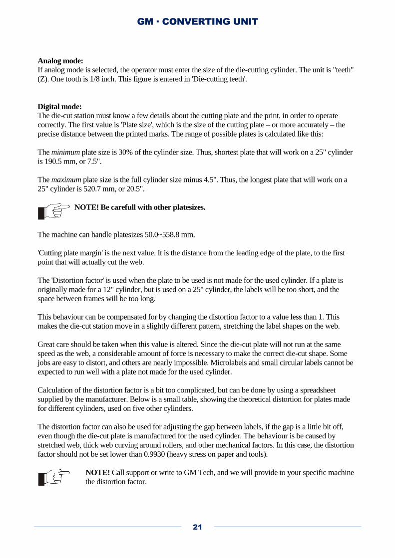
This converting unit is equipped with a die-cutting station, which can run in several modes. Correct setup
is crucial to the operation of the die-cutting station. Remember to change the plate in the die cut station
before entering new parameters. The die cut covers can be opned from the side and a new plate inserted.
First set the correct die-cut mode:
No die-cutting: The die-cut station is not used, and the die-cut cylinder cannot be engaged. However, the
cylinder will still rotate when the machine runs, to reduce web friction.
Analog die-cutting: Traditional die-cutting, with a die-cut cylinder between 10" and 25". The resolution
is 1/8" (1z).
Digital die-cutting: Semi-rotation die-cutting with a die-cut cylinder between 12" and 25". The cylinder
must be made specially for digital die-cutting.
Then enter the relevant information. If 'No die-cutting' is selected, no further information is necessary.
'Blank labels': The die-cutting station cuts, but doesn't use printed marks. It is meant to be used only on a
non-printed web.
'Number of labels on cutting plate': This is for the label counter. Every time the die-cut station has made a
full rotation in register, the label counter is increased with this number.
GM · CONVERTING UNIT
21
Analog mode:
If analog mode is selected, the operator must enter the size of the die-cutting cylinder. The unit is "teeth"
(Z). One tooth is 1/8 inch. This figure is entered in 'Die-cutting teeth'.
Digital mode:
The die-cut station must know a few details about the cutting plate and the print, in order to operate
correctly. The first value is 'Plate size', which is the size of the cutting plate – or more accurately – the
precise distance between the printed marks. The range of possible plates is calculated like this:
The minimum plate size is 30% of the cylinder size. Thus, shortest plate that will work on a 25" cylinder
is 190.5 mm, or 7.5".
The maximum plate size is the full cylinder size minus 4.5". Thus, the longest plate that will work on a
25" cylinder is 520.7 mm, or 20.5".
NOTE! Be carefull with other platesizes.
The machine can handle platesizes 50.0~558.8 mm.
'Cutting plate margin' is the next value. It is the distance from the leading edge of the plate, to the first
point that will actually cut the web.
The 'Distortion factor' is used when the plate to be used is not made for the used cylinder. If a plate is
originally made for a 12" cylinder, but is used on a 25" cylinder, the labels will be too short, and the
space between frames will be too long.
This behaviour can be compensated for by changing the distortion factor to a value less than 1. This
makes the die-cut station move in a slightly different pattern, stretching the label shapes on the web.
Great care should be taken when this value is altered. Since the die-cut plate will not run at the same
speed as the web, a considerable amount of force is necessary to make the correct die-cut shape. Some
jobs are easy to distort, and others are nearly impossible. Microlabels and small circular labels cannot be
expected to run well with a plate not made for the used cylinder.
Calculation of the distortion factor is a bit too complicated, but can be done by using a spreadsheet
supplied by the manufacturer. Below is a small table, showing the theoretical distortion for plates made
for different cylinders, used on five other cylinders.
The distortion factor can also be used for adjusting the gap between labels, if the gap is a little bit off,
even though the die-cut plate is manufactured for the used cylinder. The behaviour is be caused by
stretched web, thick web curving around rollers, and other mechanical factors. In this case, the distortion
factor should not be set lower than 0.9930 (heavy stress on paper and tools).
NOTE! Call support or write to GM Tech, and we will provide to your specific machine
the distortion factor.
GM · CONVERTING UNIT
22
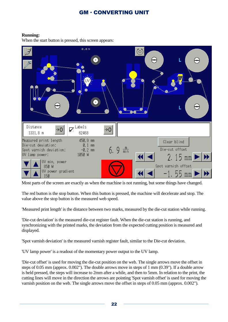
Running:
When the start button is pressed, this screen appears:
Most parts of the screen are exactly as when the machine is not running, but some things have changed.
The red button is the stop button. When this button is pressed, the machine will decelerate and stop. The
value above the stop button is the measured web speed.
'Measured print length' is the distance between two marks, measured by the die-cut station while running.
'Die-cut deviation' is the measured die-cut register fault. When the die-cut station is running, and
synchronizing with the printed marks, the deviation from the expected cutting position is measured and
displayed.
'Spot varnish deviation' is the measured varnish register fault, similar to the Die-cut deviation.
'UV lamp power' is a readout of the momentary power output to the UV lamp.
'Die-cut offset' is used for moving the die-cut position on the web. The single arrows move the offset in
steps of 0.05 mm (approx. 0.002"). The double arrows move in steps of 1 mm (0.39"). If a double arrow
is held pressed, the steps will increase to 2mm after a while, and then to 5mm. In relation to the print, the
cutting lines will move in the direction the arrows are pointing 'Spot varnish offset' is used for moving the
varnish position on the web. The single arrows move the offset in steps of 0.05 mm (approx. 0.002").

GM · CONVERTING UNIT
23
The double arrows move in steps of 1 mm (0.39"). If a double arrow is held pressed, the steps will
increase to 2mm after a while, and then to 5mm. In relation to the print, the varnish position will move in
the direction the arrows are pointing. The offset can also be adjusted on a knob mounted on the varnish
station.
The 'Clear blind' button is for syncronizing the die-cut station with the printed web, using a specific
registry mark. When the machine is die-cutting, the mark reader will "go blind" after reading the first
printed mark, and will continue being blind for 90% of the die-cut plate size. E.g. with a 12" plate, the
mark reader will be blind for 10.8" after reading the first mark. When 'Clear blind' is pressed, the die-cut
station will forget all about the previous marks, and use the following mark as a registry mark.
5.3. Speed control
The web speed is mainly controlled by the speed potentiometer. However, the different modes and
possibilities give different speed limits.
When running offline, without the die-cut station, the speed limit is 70 m/min, and the speed is solely
controlled with the speed potentiometer. In analog mode, the speed is limited to approx. 72 m/min. In
digital die-cut mode, the speed limit depends on which job is running, but the absolute limit is 35 m/min.
The following tables show the approximate speed limits relating to different job setups.
When running inline, the speed is controlled partly with the speed potentiometer, and partly by the
dancer arm. Therefore, when running inline, the speed potentiometer must be turned up. Otherwise, the
web will not move. Usually, a setting of about 4-5 is adequate.
GM · CONVERTING UNIT
24
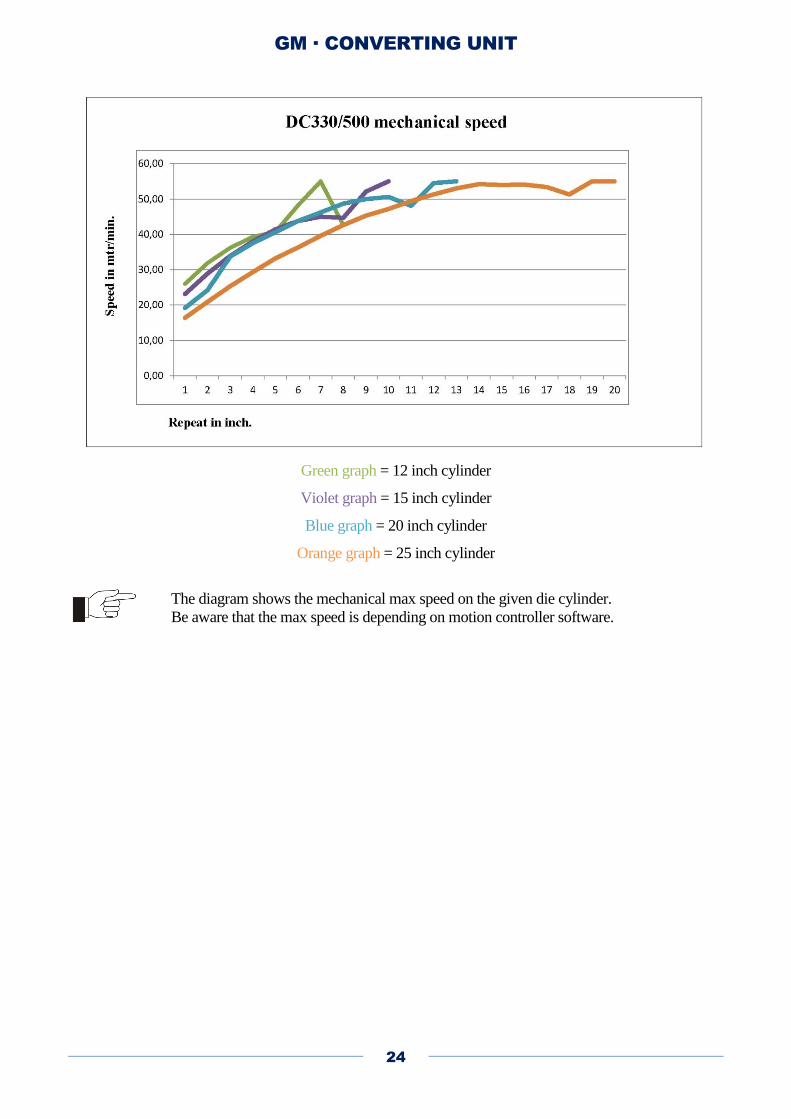
Green graph = 12 inch cylinder
Violet graph = 15 inch cylinder
Blue graph = 20 inch cylinder
Orange graph = 25 inch cylinder
The diagram shows the mechanical max speed on the given die cylinder.
Be aware that the max speed is depending on motion controller software.
GM · CONVERTING UNIT
25
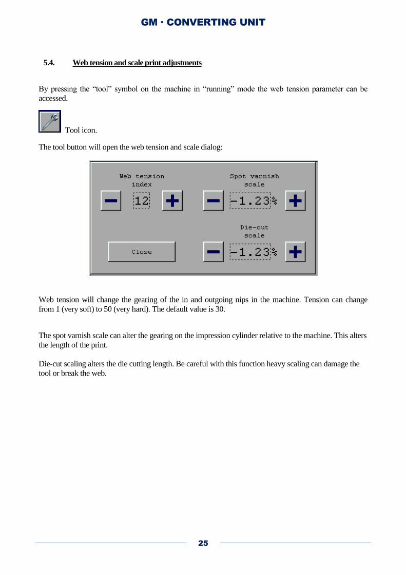
5.4. Web tension and scale print adjustments
By pressing the “tool” symbol on the machine in “running” mode the web tension parameter can be
accessed.
Tool icon.
The tool button will open the web tension and scale dialog:
Web tension will change the gearing of the in and outgoing nips in the machine. Tension can change
from 1 (very soft) to 50 (very hard). The default value is 30.
The spot varnish scale can alter the gearing on the impression cylinder relative to the machine. This alters
the length of the print.
Die-cut scaling alters the die cutting length. Be careful with this function heavy scaling can damage the
tool or break the web.
GM · CONVERTING UNIT
26
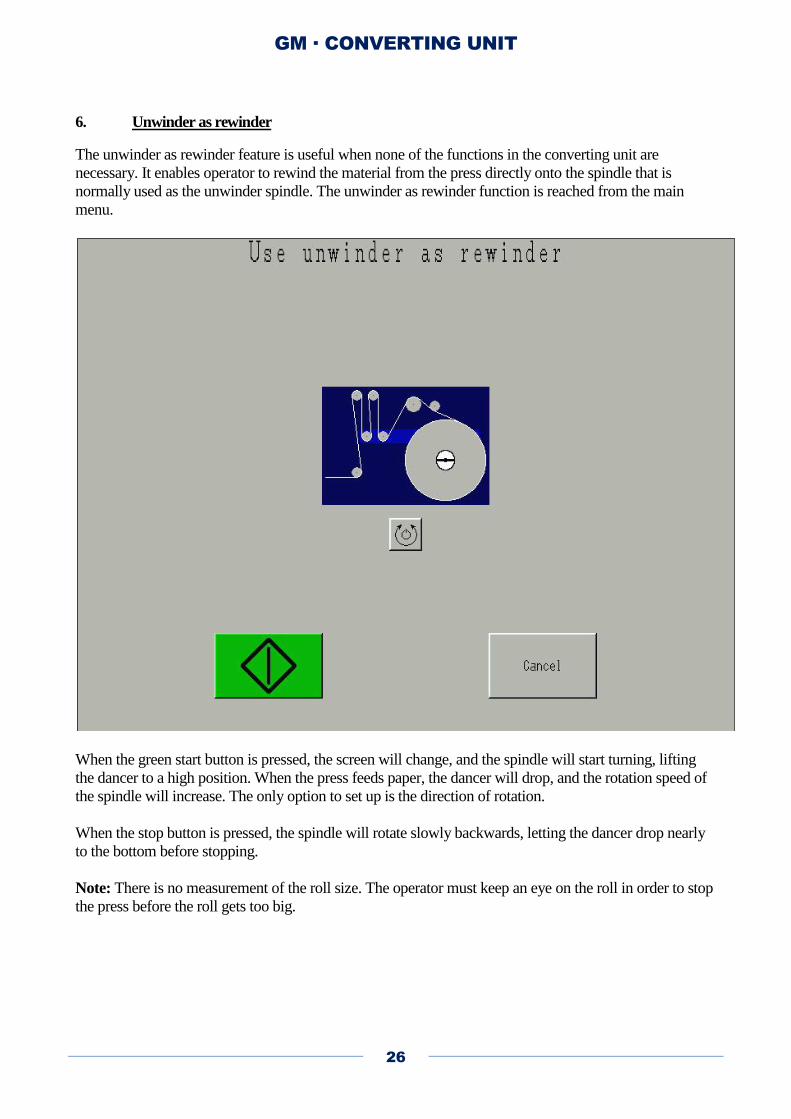
6. Unwinder as rewinder
The unwinder as rewinder feature is useful when none of the functions in the converting unit are
necessary. It enables operator to rewind the material from the press directly onto the spindle that is
normally used as the unwinder spindle. The unwinder as rewinder function is reached from the main
menu.
When the green start button is pressed, the screen will change, and the spindle will start turning, lifting
the dancer to a high position. When the press feeds paper, the dancer will drop, and the rotation speed of
the spindle will increase. The only option to set up is the direction of rotation.
When the stop button is pressed, the spindle will rotate slowly backwards, letting the dancer drop nearly
to the bottom before stopping.
Note: There is no measurement of the roll size. The operator must keep an eye on the roll in order to stop
the press before the roll gets too big.
GM · CONVERTING UNIT
27
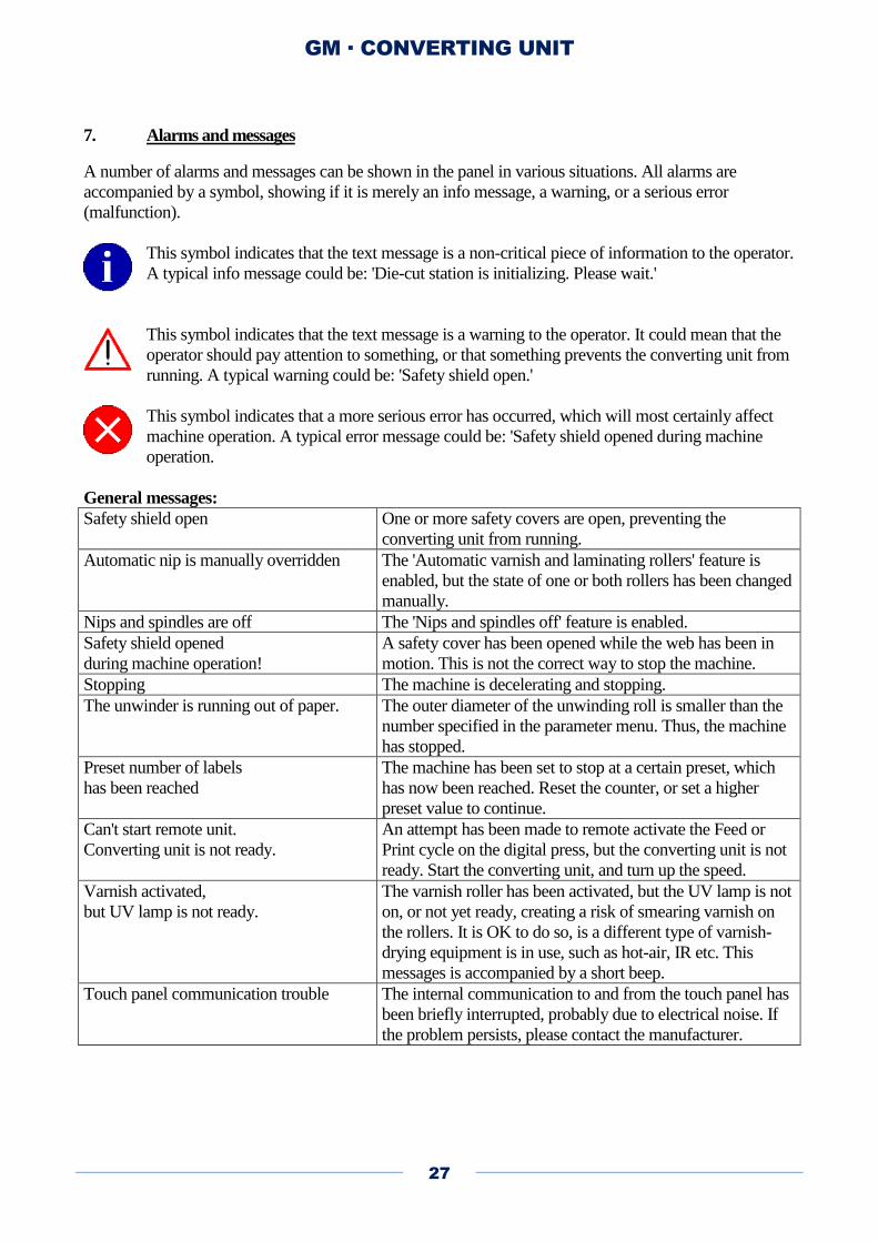
7. Alarms and messages
A number of alarms and messages can be shown in the panel in various situations. All alarms are
accompanied by a symbol, showing if it is merely an info message, a warning, or a serious error
(malfunction).
This symbol indicates that the text message is a non-critical piece of information to the operator.
A typical info message could be: 'Die-cut station is initializing. Please wait.'
This symbol indicates that the text message is a warning to the operator. It could mean that the
operator should pay attention to something, or that something prevents the converting unit from
running. A typical warning could be: 'Safety shield open.'
This symbol indicates that a more serious error has occurred, which will most certainly affect
machine operation. A typical error message could be: 'Safety shield opened during machine
operation.
General messages:
Safety shield open One or more safety covers are open, preventing the
converting unit from running.
Automatic nip is manually overridden The 'Automatic varnish and laminating rollers' feature is
enabled, but the state of one or both rollers has been changed
manually.
Nips and spindles are off The 'Nips and spindles off' feature is enabled.
Safety shield opened
during machine operation!
A safety cover has been opened while the web has been in
motion. This is not the correct way to stop the machine.
Stopping The machine is decelerating and stopping.
The unwinder is running out of paper. The outer diameter of the unwinding roll is smaller than the
number specified in the parameter menu. Thus, the machine
has stopped.
Preset number of labels
has been reached
The machine has been set to stop at a certain preset, which
has now been reached. Reset the counter, or set a higher
preset value to continue.
Can't start remote unit.
Converting unit is not ready.
An attempt has been made to remote activate the Feed or
Print cycle on the digital press, but the converting unit is not
ready. Start the converting unit, and turn up the speed.
Varnish activated,
but UV lamp is not ready.
The varnish roller has been activated, but the UV lamp is not
on, or not yet ready, creating a risk of smearing varnish on
the rollers. It is OK to do so, is a different type of varnish-
drying equipment is in use, such as hot-air, IR etc. This
messages is accompanied by a short beep.
Touch panel communication trouble The internal communication to and from the touch panel has
been briefly interrupted, probably due to electrical noise. If
the problem persists, please contact the manufacturer.
GM · CONVERTING UNIT
28
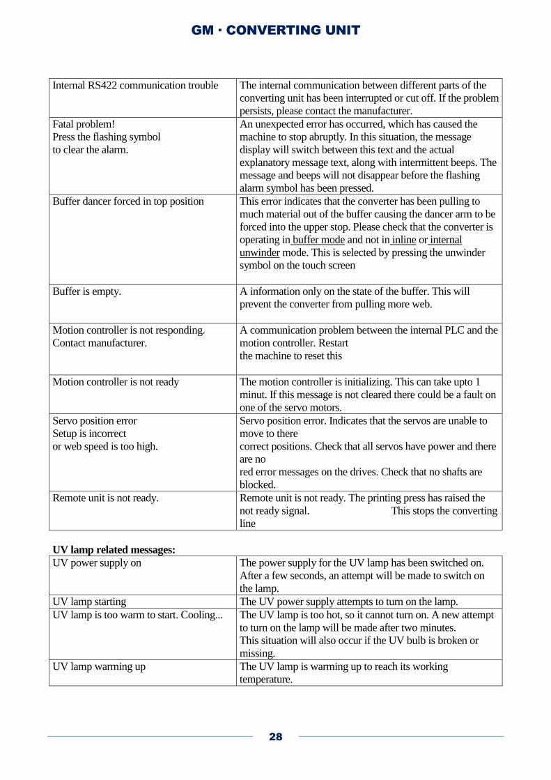
Internal RS422 communication trouble The internal communication between different parts of the
converting unit has been interrupted or cut off. If the problem
persists, please contact the manufacturer.
Fatal problem!
Press the flashing symbol
to clear the alarm.
An unexpected error has occurred, which has caused the
machine to stop abruptly. In this situation, the message
display will switch between this text and the actual
explanatory message text, along with intermittent beeps. The
message and beeps will not disappear before the flashing
alarm symbol has been pressed.
Buffer dancer forced in top position This error indicates that the converter has been pulling to
much material out of the buffer causing the dancer arm to be
forced into the upper stop. Please check that the converter is
operating in buffer mode and not in inline or internal
unwinder mode. This is selected by pressing the unwinder
symbol on the touch screen
Buffer is empty. A information only on the state of the buffer. This will
prevent the converter from pulling more web.
Motion controller is not responding.
Contact manufacturer.
A communication problem between the internal PLC and the
motion controller. Restart
the machine to reset this
Motion controller is not ready The motion controller is initializing. This can take upto 1
minut. If this message is not cleared there could be a fault on
one of the servo motors.
Servo position error
Setup is incorrect
or web speed is too high.
Servo position error. Indicates that the servos are unable to
move to there
correct positions. Check that all servos have power and there
are no
red error messages on the drives. Check that no shafts are
blocked.
Remote unit is not ready. Remote unit is not ready. The printing press has raised the
not ready signal. This stops the converting
line
UV lamp related messages:
UV power supply on The power supply for the UV lamp has been switched on.
After a few seconds, an attempt will be made to switch on
the lamp.
UV lamp starting The UV power supply attempts to turn on the lamp.
UV lamp is too warm to start. Cooling... The UV lamp is too hot, so it cannot turn on. A new attempt
to turn on the lamp will be made after two minutes.
This situation will also occur if the UV bulb is broken or
missing.
UV lamp warming up The UV lamp is warming up to reach its working
temperature.
GM · CONVERTING UNIT
29
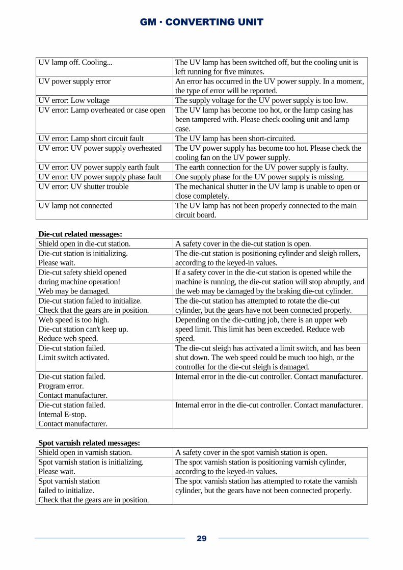
UV lamp off. Cooling... The UV lamp has been switched off, but the cooling unit is
left running for five minutes.
UV power supply error An error has occurred in the UV power supply. In a moment,
the type of error will be reported.
UV error: Low voltage The supply voltage for the UV power supply is too low.
UV error: Lamp overheated or case open The UV lamp has become too hot, or the lamp casing has
been tampered with. Please check cooling unit and lamp
case.
UV error: Lamp short circuit fault The UV lamp has been short-circuited.
UV error: UV power supply overheated The UV power supply has become too hot. Please check the
cooling fan on the UV power supply.
UV error: UV power supply earth fault The earth connection for the UV power supply is faulty.
UV error: UV power supply phase fault One supply phase for the UV power supply is missing.
UV error: UV shutter trouble The mechanical shutter in the UV lamp is unable to open or
close completely.
UV lamp not connected The UV lamp has not been properly connected to the main
circuit board.
Die-cut related messages:
Shield open in die-cut station. A safety cover in the die-cut station is open.
Die-cut station is initializing.
Please wait.
The die-cut station is positioning cylinder and sleigh rollers,
according to the keyed-in values.
Die-cut safety shield opened
during machine operation!
Web may be damaged.
If a safety cover in the die-cut station is opened while the
machine is running, the die-cut station will stop abruptly, and
the web may be damaged by the braking die-cut cylinder.
Die-cut station failed to initialize.
Check that the gears are in position.
The die-cut station has attempted to rotate the die-cut
cylinder, but the gears have not been connected properly.
Web speed is too high.
Die-cut station can't keep up.
Reduce web speed.
Depending on the die-cutting job, there is an upper web
speed limit. This limit has been exceeded. Reduce web
speed.
Die-cut station failed.
Limit switch activated.
The die-cut sleigh has activated a limit switch, and has been
shut down. The web speed could be much too high, or the
controller for the die-cut sleigh is damaged.
Die-cut station failed.
Program error.
Contact manufacturer.
Internal error in the die-cut controller. Contact manufacturer.
Die-cut station failed.
Internal E-stop.
Contact manufacturer.
Internal error in the die-cut controller. Contact manufacturer.
Spot varnish related messages:
Shield open in varnish station. A safety cover in the spot varnish station is open.
Spot varnish station is initializing.
Please wait.
The spot varnish station is positioning varnish cylinder,
according to the keyed-in values.
Spot varnish station
failed to initialize.
Check that the gears are in position.
The spot varnish station has attempted to rotate the varnish
cylinder, but the gears have not been connected properly.

GM · CONVERTING UNIT
30
Spot varnish position error. The spot varnish station has been mechanically blocked,
disabled, or is by other means prevented from reaching its
correct position.
Spot varnish station failed.
Program error.
Contact manufacturer.
Internal error in the spot varnish controller. Contact
manufacturer.
Spot varnish station failed.
Internal E-stop.
Contact manufacturer.
Internal error in the spot varnish controller. Contact
manufacturer.
GM · CONVERTING UNIT
31
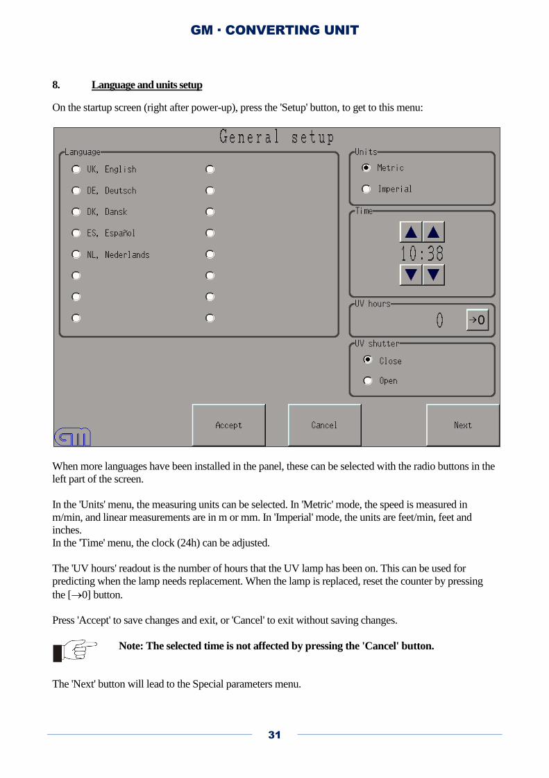
8. Language and units setup
On the startup screen (right after power-up), press the 'Setup' button, to get to this menu:
When more languages have been installed in the panel, these can be selected with the radio buttons in the
left part of the screen.
In the 'Units' menu, the measuring units can be selected. In 'Metric' mode, the speed is measured in
m/min, and linear measurements are in m or mm. In 'Imperial' mode, the units are feet/min, feet and
inches.
In the 'Time' menu, the clock (24h) can be adjusted.
The 'UV hours' readout is the number of hours that the UV lamp has been on. This can be used for
predicting when the lamp needs replacement. When the lamp is replaced, reset the counter by pressing
the [0] button.
Press 'Accept' to save changes and exit, or 'Cancel' to exit without saving changes.
Note: The selected time is not affected by pressing the 'Cancel' button.
The 'Next' button will lead to the Special parameters menu.
GM · CONVERTING UNIT
32
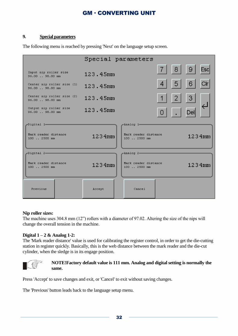
9. Special parameters
The following menu is reached by pressing 'Next' on the language setup screen.
Nip roller sizes:
The machine uses 304.8 mm (12”) rollers with a diameter of 97.02. Altering the size of the nips will
change the overall tension in the machine.
Digital 1 – 2 & Analog 1-2: The 'Mark reader distance' value is used for calibrating the register control, in order to get the die-cutting
station in register quickly. Basically, this is the web distance between the mark reader and the die-cut
cylinder, when the sledge is in its engage position.
NOTE!Factory default value is 111 mm. Analog and digital setting is normally the
same.
Press 'Accept' to save changes and exit, or 'Cancel' to exit without saving changes.
The 'Previous' button leads back to the language setup menu.
GM · CONVERTING UNIT
33
10. Registration accuracy
The registration accuracy is defined as the deviation in the first cutting line relative to the registration
mark. If there is deviations due to differences in gab size between the labels, it has to do with the
distortion setting or the dispro factor of the plate. To get the best possible results do the following:
1. Select the shortest possible plate. The ideal situation is one label row pr. rotation, if this is not
possible go for 2,3,4. The machine gains accuracy as the distance between registration marks
shortens. For optimal economy it is acceptable to use the longest possible repeat on the print
engine, but remember to put several registration marks in the repeat, a shorter plate can be used.
Remember to put only one registration mark per plate length.
2. Measure and check that the printed repeat length exactly matches the plate repeat.
3. Measure and check that the plate edge to first cutting distance is entered correctly
4. Run with all nips down.
5. Secure that the die is correctly shimmed up (no lateral movement) and the inductive sensor
behind the die is correctly adjusted (2mm from die tooth wheel)
6. Secure that the mark reader focus distance is 9 mm
7. The repeat distance must never be less than the distance between the mark reader and the die (this
is only the case if the mark reader has been moved) om the first cut line. If this happens, machine
will die cut a labels based on the registration mark for the next label. This will reduce precision.
8. The space between register marks must never be less than 50mm
9. Do not die cut across print engine frames (Always align the register mark with the frame start)
GM · CONVERTING UNIT
34
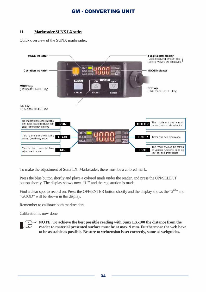
11. Markreader SUNX LX series
Quick overview of the SUNX markreader.
To make the adjustment of Sunx LX Markreader, there must be a colored mark.
Press the blue button shortly and place a colored mark under the reader, and press the ON/SELECT
button shortly. The display shows now. “1st” and the registration is made.
Find a clear spot to record on. Press the OFF/ENTER button shortly and the display shows the “2nd
” and
“GOOD” will be shown in the display.
Remember to calibrate both markreaders.
Calibration is now done.
NOTE! To achieve the best possible reading with Sunx LX-100 the distance from the
reader to material presented surface must be at max. 9 mm. Furthermore the web have
to be as stable as possible. Be sure to webtension is set correctly, same as webguides.
GM · CONVERTING UNIT
35
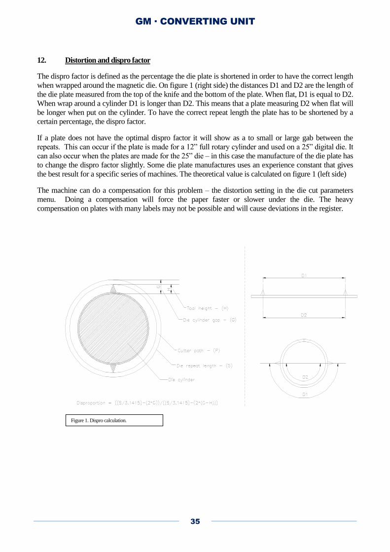
12. Distortion and dispro factor
The dispro factor is defined as the percentage the die plate is shortened in order to have the correct length
when wrapped around the magnetic die. On figure 1 (right side) the distances D1 and D2 are the length of
the die plate measured from the top of the knife and the bottom of the plate. When flat, D1 is equal to D2.
When wrap around a cylinder D1 is longer than D2. This means that a plate measuring D2 when flat will
be longer when put on the cylinder. To have the correct repeat length the plate has to be shortened by a
certain percentage, the dispro factor.
If a plate does not have the optimal dispro factor it will show as a to small or large gab between the
repeats. This can occur if the plate is made for a 12” full rotary cylinder and used on a 25” digital die. It
can also occur when the plates are made for the 25” die – in this case the manufacture of the die plate has
to change the dispro factor slightly. Some die plate manufactures uses an experience constant that gives
the best result for a specific series of machines. The theoretical value is calculated on figure 1 (left side)
The machine can do a compensation for this problem – the distortion setting in the die cut parameters
menu. Doing a compensation will force the paper faster or slower under the die. The heavy
compensation on plates with many labels may not be possible and will cause deviations in the register.
Figure 1. Dispro calculation.
GM · CONVERTING UNIT
36
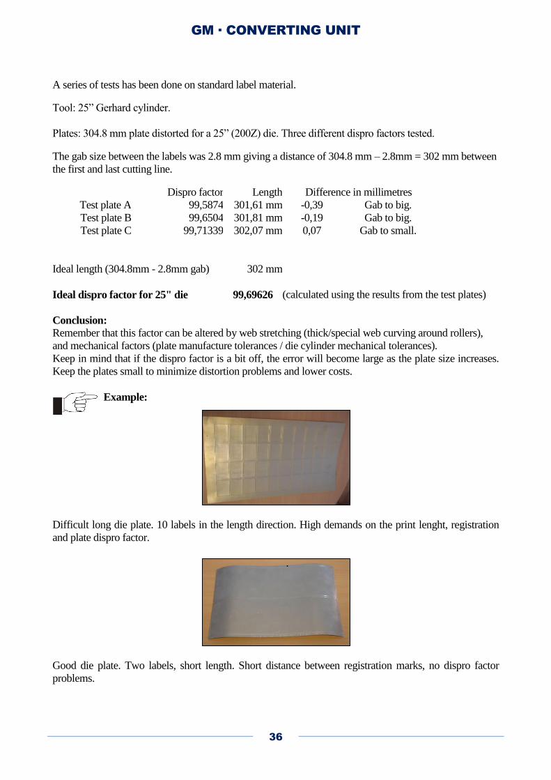
A series of tests has been done on standard label material.
Tool: 25” Gerhard cylinder.
Plates: 304.8 mm plate distorted for a 25” (200Z) die. Three different dispro factors tested.
The gab size between the labels was 2.8 mm giving a distance of 304.8 mm – 2.8mm = 302 mm between
the first and last cutting line.
Dispro factor Length Difference in millimetres
Test plate A 99,5874 301,61 mm -0,39 Gab to big.
Test plate B 99,6504 301,81 mm -0,19 Gab to big.
Test plate C 99,71339 302,07 mm 0,07 Gab to small.
Ideal length (304.8mm - 2.8mm gab) 302 mm
Ideal dispro factor for 25" die 99,69626 (calculated using the results from the test plates)
Conclusion:
Remember that this factor can be altered by web stretching (thick/special web curving around rollers),
and mechanical factors (plate manufacture tolerances / die cylinder mechanical tolerances).
Keep in mind that if the dispro factor is a bit off, the error will become large as the plate size increases.
Keep the plates small to minimize distortion problems and lower costs.
Example:
Difficult long die plate. 10 labels in the length direction. High demands on the print lenght, registration
and plate dispro factor.
.
Good die plate. Two labels, short length. Short distance between registration marks, no dispro factor
problems.
GM · CONVERTING UNIT
37
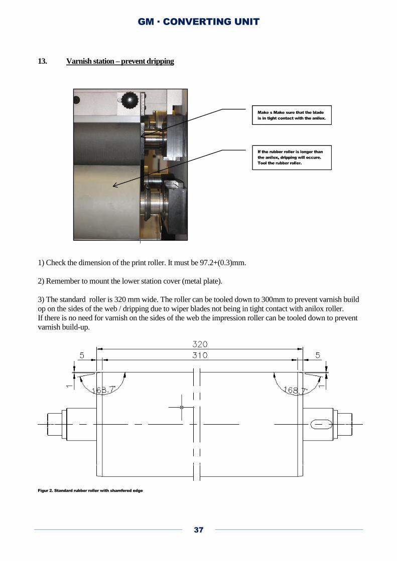
13. Varnish station – prevent dripping
1) Check the dimension of the print roller. It must be 97.2+(0.3)mm.
2) Remember to mount the lower station cover (metal plate).
3) The standard roller is 320 mm wide. The roller can be tooled down to 300mm to prevent varnish build
op on the sides of the web / dripping due to wiper blades not being in tight contact with anilox roller.
If there is no need for varnish on the sides of the web the impression roller can be tooled down to prevent
varnish build-up.
Figur 2. Standard rubber roller with shamfered edge
GM · CONVERTING UNIT
38
14. Dust problems with V-knifes & damages to anvil roller.
This issue does only relate to machine with V-knifes. Rotary knife systems does not have dust problems.
The standard V-knife has an angel of 45, this can generate dust with some materials. If there is a
problem, we can deliver a knife with a 30 angel to fix this problem. This knife is sharper and have a
shorter life cycle. Remember to limit the air-pressure to a minimum (what is needed to just cut through
the paper).
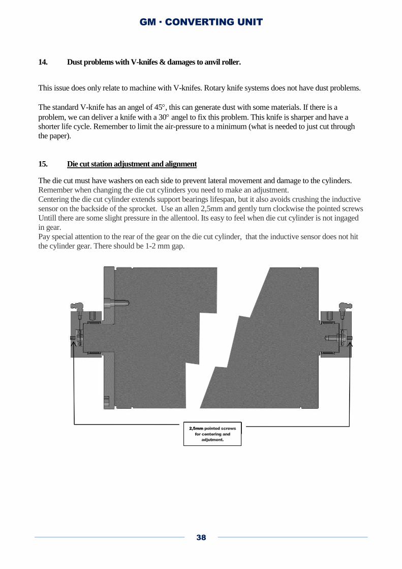
15. Die cut station adjustment and alignment
The die cut must have washers on each side to prevent lateral movement and damage to the cylinders.
Remember when changing the die cut cylinders you need to make an adjustment.
Centering the die cut cylinder extends support bearings lifespan, but it also avoids crushing the inductive
sensor on the backside of the sprocket. Use an allen 2,5mm and gently turn clockwise the pointed screws
Untill there are some slight pressure in the allentool. Its easy to feel when die cut cylinder is not ingaged
in gear.
Pay special attention to the rear of the gear on the die cut cylinder, that the inductive sensor does not hit
the cylinder gear. There should be 1-2 mm gap.

GM · CONVERTING UNIT
39
16. Die cut bridge adjustment
To adjust the stroke of the die bridge follow this procedure
1. Dismount the bridge and put it on a table or stable surface.
2. Use an allan key and a wrench to adjust the gab at the 4. set points.
3. Make the top nut lose and turn the bolt until the clearance is 1.25mm
4. Hold the bolt with the allan key and lock the nut.
5. All 4. set points must have the same distance.
6. Remount the bridge
GM · CONVERTING UNIT
40
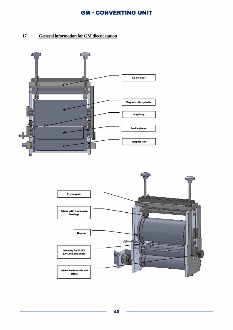
17. General information for GM diecut station

GM · CONVERTING UNIT
41
18. Pneumatic air cylinders
The two air cylinders can disengage the magnetic die cylinder because the die is supported with springs
below the bearing houses. The stroke of the piston plate is 1.5mm, enough to stop die cutting, but not
enough to get the cog wheels out of grip. The air pressure must be 5 to 6 bar.
The air cylinders has an area of 400cm2 and will press down the piston plate with much higher pressure
than is needed to die cut (20.000N) not to give in.
The pressure from the air cylinders is only to move the die up and down and has nothing to do with the
pressure you use for die cutting, this is adjusted with the pressure screws.
WARNING:
Secure that the pressure screws are not tighten before you engage the die, - it can damage
the die because of to much pressure.

GM · CONVERTING UNIT
42
Gap:
The “gap” is the distance between the surface of the die cylinder and the surface of the anvil cylinder.
The distance cannot be adjusted because the bearers on the cylinders control it. The gap on GM machines
is 0,48mm (label) or 0,76mm (postcards etc.)
Pressure adjusting:
When the die is engaged (down) adjust the pressure so high that you get a perfect die cut and not higher.
If the machine has Kocher & Beck pressure screws with manometers on the converting from the scaling
on the manometers is:
60 bar = 2116N
100bar = 3527N
160 bar = 5642N
200 bar = 7052N
1bar = 35,26N
The pressure should never exceed 20N/mm ( 283 bar on 500mm web width and 187 bar for 330mm web
width)
If you cannot get a perfect die cut it is properly not a correct die plate.
Do not try to fix it by increasing the pressure, - it will only damage the magnetic die cylinder, - get a
correct plate.
WARNING:
Never use tools to tighten the pressure screws!
Never tighten the pressure screws and then put down the die!

GM · CONVERTING UNIT
43
19. Varnish station
The UV-varnishing unit is used after the digital printing unit to varnish the web. The varnishing unit is
designed for the use of UV - curing ink/lacquer. Also water based priming is possible with hot air dryer
mounted. Before the varnish station is used: Please check that the dimension of the Print roller diameter
is correct. It must be 97.2+0.3mm.
19.1. Technical data
Web widthmax: 330 mm
Plate cylinder diameter 97.02mm
Print roller diameter (replaces plate cylinder when flood varnish is used) 97.2+0.3mm
Printing widthmax: 310 mm
Printing lengthmin: 9“
Printing lengthmax: 19”
Increments: 1/8”
UV-lamp, effectmax: 5000 W
Continuously variable between 300 W and 5000 W
1. Handle for mounting ductorblade.
2. Handle for mounting anilox roller.
3. Handle for mounting of ink roller.
2
3
1

GM · CONVERTING UNIT
44
The paper web is fed through the press on stationary rollers (impression rollers and turning rollers).
Above the web is the print head with the plate cylinder, which can be raised and lowered. The plate is
inked up by the anilox roller, which is adjusted with two handles to more or less pressure on the plate
roller. The anilox roller is inked up by the inking roller in the ink tray.
Paper web
Impression cyllinder
Plate cylinder
Anilox roller
Inking roller
Ink tray

GM · CONVERTING UNIT
45
19.2. Anilox roller types
The amount of the ink to be transferred to the plate and paper web is determinate by the form and size of
the anilox roller's cells.
If a lot of ink is to be transferred to the paper web an anilox roller with a coarser screen - low line number
- must be used, If less ink is required e.g. for half tone printing, an anilox roller with a finer screen -
higher line number - is used.
Normally anilox rollers with a screen number between 60-240 lines per cm are used.
The selection of anilox roller depends on type of ink and colour density. As a general indication for
selection of anilox roller the following can be stated (as an indication only).
GM · CONVERTING UNIT
46
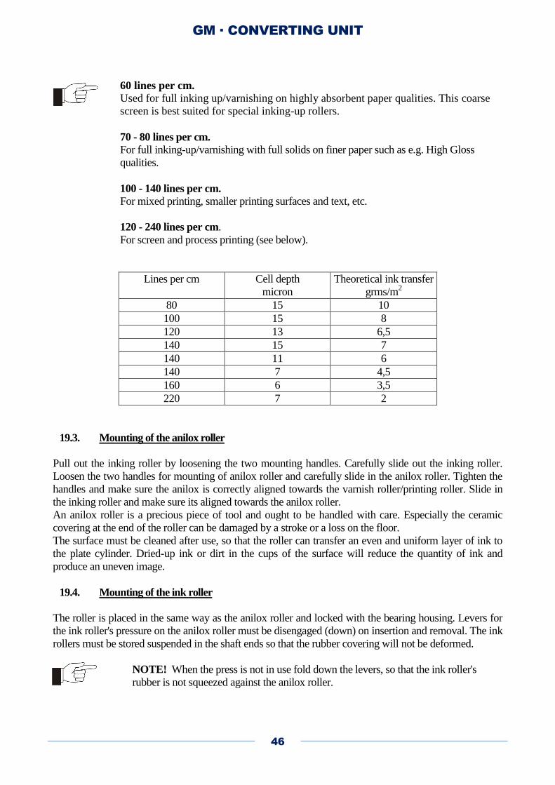
60 lines per cm. Used for full inking up/varnishing on highly absorbent paper qualities. This coarse
screen is best suited for special inking-up rollers.
70 - 80 lines per cm.
For full inking-up/varnishing with full solids on finer paper such as e.g. High Gloss
qualities.
100 - 140 lines per cm.
For mixed printing, smaller printing surfaces and text, etc.
120 - 240 lines per cm.
For screen and process printing (see below).
Lines per cm Cell depth
micron
Theoretical ink transfer
grms/m2
80 15 10
100 15 8
120 13 6,5
140 15 7
140 11 6
140 7 4,5
160 6 3,5
220 7 2
19.3. Mounting of the anilox roller
Pull out the inking roller by loosening the two mounting handles. Carefully slide out the inking roller.
Loosen the two handles for mounting of anilox roller and carefully slide in the anilox roller. Tighten the
handles and make sure the anilox is correctly aligned towards the varnish roller/printing roller. Slide in
the inking roller and make sure its aligned towards the anilox roller.
An anilox roller is a precious piece of tool and ought to be handled with care. Especially the ceramic
covering at the end of the roller can be damaged by a stroke or a loss on the floor.
The surface must be cleaned after use, so that the roller can transfer an even and uniform layer of ink to
the plate cylinder. Dried-up ink or dirt in the cups of the surface will reduce the quantity of ink and
produce an uneven image.
19.4. Mounting of the ink roller
The roller is placed in the same way as the anilox roller and locked with the bearing housing. Levers for
the ink roller's pressure on the anilox roller must be disengaged (down) on insertion and removal. The ink
rollers must be stored suspended in the shaft ends so that the rubber covering will not be deformed.
NOTE! When the press is not in use fold down the levers, so that the ink roller's
rubber is not squeezed against the anilox roller.

GM · CONVERTING UNIT
47
19.5. Mounting of side blades and doctor blade
1. Knurled nut for blade adjustment.
2 .Fixing of side wipers.
3. Doctorblade with outward bevelling.
4.Sidewiper.
The doctor blade can be adjusted when there is ink on the anilox roller. Adjust the two knurled nuts so
that the doctor blade can just reach in and wipe off the ink with a light pressure on the anilox roller.
The inking roller is pressed lightly against the anilox roller, giving a thick coat of ink. The blade is
adjusted on the two knurled nuts so the ink is wiped off evenly in the entire width. The levers are moved
up so the ink layer disappears and down until correct pressure is achieved. There will be ink stripes with a
film of ink between them below the doctor blade. The reverse angle blade doses the same quantity of ink
to the anilox roller at all speeds.
1
3
2
4
GM · CONVERTING UNIT
48
NOTE! The blade may not be set too hard as both doctor blade and anilox roller will be
exposed to unnecessary wear and tear.
NOTE! The blade may only be ON when there is ink on the roller. Ink reduces friction.
Impurities in the ink or dried ink residues can damage the doctor blade, giving lines in the
image and at worst scratches in the anilox roller.
NOTE! If the doctor blade is damaged wiping will be uneven.
NOTE! A scratch may damage an anilox roller.
A defect doctor blade can be replaced by releasing the five screws on the blade holder.
The blade is pulled out. A new one is inserted and clamped, parallel with the blade
holder, so that the bevelling faces outwards.
Adjust the side wipers as close to the anilox as possible. If there is a gap between the wiper and the
anilox, dripping will become a problem.
19.6. Filling of ink
Fill in sufficient ink for the ink roller to be inked up during rotation. It is possible to connect an ink-pump
for automatic filling of the ink tray. If ink-pump is connected, use an overflow pipe in the ink tray drain
hole in order to drain excess ink/varnish.
NOTE! When UV varnish is used cover the station with a blanket when stopping the
daily production. This will prevent light access to the ink tray and unintentionally ink dry
up.
NOTE! When using water based inks the entire station must be cleaned after production.
19.7. Mounting of print cylinder
The plate is mounted on the aluminium plate cylinder with the proper tape (see flexo plate
documentation). Make sure that the plate cylinder gear wheel has the correct size (the gear increment is 8
teeth per inch).
After plate mounting slide the plate cylinder into the flexo unit. Lower the plate cylinder until the gear
wheels are in mesh. On start the automatic print throw-off/on will lower the plate roller further.
GM · CONVERTING UNIT
49
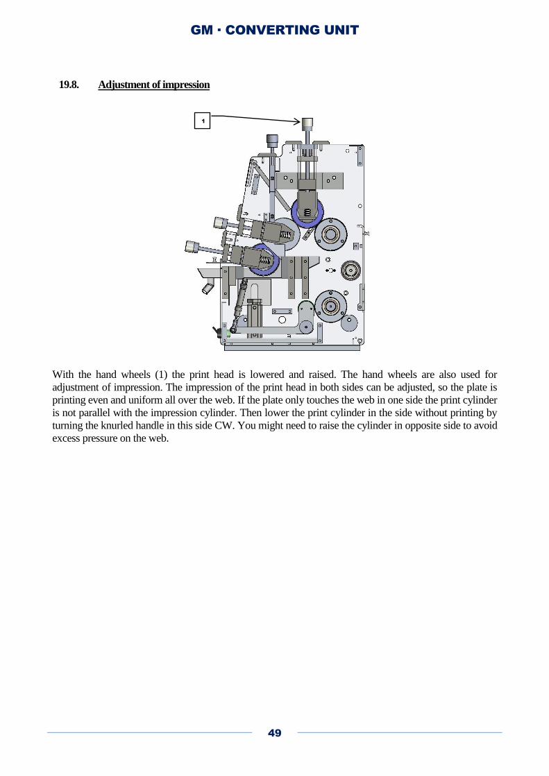
19.8. Adjustment of impression
With the hand wheels (1) the print head is lowered and raised. The hand wheels are also used for
adjustment of impression. The impression of the print head in both sides can be adjusted, so the plate is
printing even and uniform all over the web. If the plate only touches the web in one side the print cylinder
is not parallel with the impression cylinder. Then lower the print cylinder in the side without printing by
turning the knurled handle in this side CW. You might need to raise the cylinder in opposite side to avoid
excess pressure on the web.
1
GM · CONVERTING UNIT
50
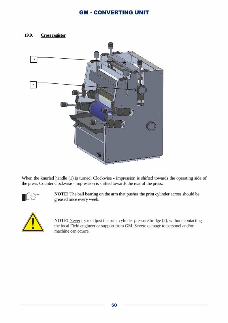
19.9. Cross register
When the knurled handle (1) is turned; Clockwise - impression is shifted towards the operating side of
the press. Counter clockwise - impression is shifted towards the rear of the press.
NOTE! The ball bearing on the arm that pushes the print cylinder across should be
greased once every week.
NOTE! Never try to adjust the print cylinder pressure bridge (2). without contacting
the local Field engineer or support from GM. Severe damage to personel and/or
machine can ocurre.
1
2

GM · CONVERTING UNIT
51
19.10. Triangle adjustment of the flexo unit (Coarse adjustment)
In order to obtain best possible varnish/print quality on the flexo unit an initial coarse adjustment is
necessary. Under normal conditions this should be performed once a month at least or every time after
cleaning the flexo unit.
Clean impression roller, varnish roller and surface of anilox roller. Activate (engage) the varnish roller in
the “main screen” (press the varnish roller in the touch screen so the symbol turns to yellow colour).
1. From the front-end of the flexo unit insert two liner paper between the impression cylinder and
the plate cylinder. Now lower the plate cylinder until it is not possible to move the liner paper. Do
not tighten the plate cylinder too much against the paper. You have to make sure the distance is
exact on both sides.
With a slightly pull in each of the liner papers the should be some tension.
2. From the backside of the flexo unit insert two liner paper between anilox roller and plate cylinder.
Now adjust the anilox roller towards the plate cylinder. Do not adjust the plate cylinder .
Gently adjust the anilox towards the plate cylinder until it grips the liner paper. You have to be
sure it grips in both sides. Do not tighten the anilox too much against the plate cylinder.
With a slightly pull in each of the liner papers the should be some tension.
GM · CONVERTING UNIT
52
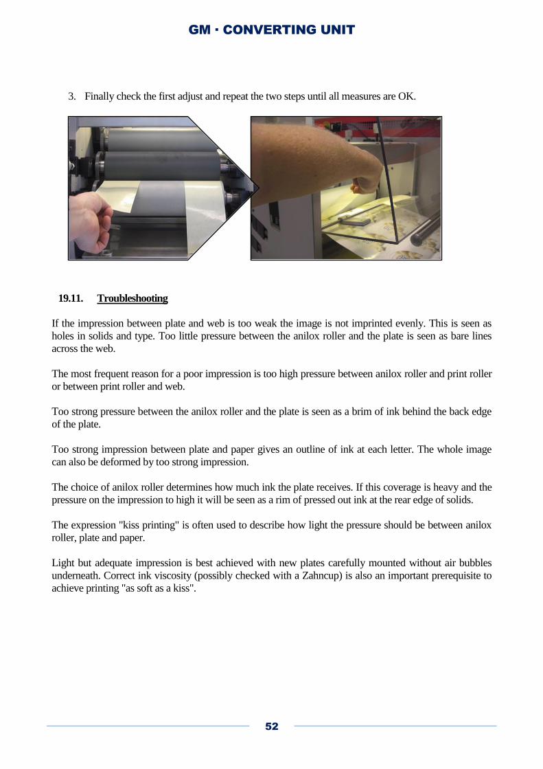
3. Finally check the first adjust and repeat the two steps until all measures are OK.
19.11. Troubleshooting
If the impression between plate and web is too weak the image is not imprinted evenly. This is seen as
holes in solids and type. Too little pressure between the anilox roller and the plate is seen as bare lines
across the web.
The most frequent reason for a poor impression is too high pressure between anilox roller and print roller
or between print roller and web.
Too strong pressure between the anilox roller and the plate is seen as a brim of ink behind the back edge
of the plate.
Too strong impression between plate and paper gives an outline of ink at each letter. The whole image
can also be deformed by too strong impression.
The choice of anilox roller determines how much ink the plate receives. If this coverage is heavy and the
pressure on the impression to high it will be seen as a rim of pressed out ink at the rear edge of solids.
The expression "kiss printing" is often used to describe how light the pressure should be between anilox
roller, plate and paper.
Light but adequate impression is best achieved with new plates carefully mounted without air bubbles
underneath. Correct ink viscosity (possibly checked with a Zahncup) is also an important prerequisite to
achieve printing "as soft as a kiss".

GM · CONVERTING UNIT
53
20. Spot varnish guide.
Introduction
The spot varnish function of the converting unit enables the system to put down print in register. This can
be used for various applications; spot varnish effects (only part of the web varnished), Cold foil (a glue is
printed in patterns to make silver/gold effects) and single color printing. The most common option is the
spot varnish effect where only a part of the web is varnished. The spot varnish only has one parameter –
the “Z” count –the number of teeth on the tooth wheel of the print cylinder. The Z unit is 1/8 of an inch or
3.175mm pr. Tooth. A 10” plate cylinder has a Z count of 10*8= 80Z and a plate size of 10”*25,4mm =
254mm.
Working principle
When equipped with a spot varnish option the print plate cylinder in the flexo graphic station is driven by
an independent motor. This means that the print plates cylinder can be synchronized with the web using a
print mark reader located next to the station. To make sure printing starts in the same position every time
a job is setup the system makes a “homing” when a new cylinder is loaded. The print plate cylinder is
“homed”by turning until a small hole in the tooth wheel passes a sensor located in the frame of the flexo
station. This hole is only once (at the startup of the job). The cylinder will make a quick rotation and find
the hole. When the system is synchronized it will start to look for a mark on the web. When found the
plate cylinder is moved into a position in reference to the mark. This position can be altered by turning
the “offset knob” on the side of the station or pressing the “offset” button on the touch screen. The offset
determines the distance between the printed mark on the web and the zero hole on the cylinder.
The print plate cylinder can be lifted up and down on the touch screen of the machine. This is done by
pressing the cylinder symbol. When the print cylinder is “down” only small (+/-1mm corrections are
possible). This is done to protect the print plate cylinder from rapid movements when pressed against the
web (this could cause web break). When the cylinder is up the cylinder can make a ½ rotation of the
cylinder. This is enables the system to go quickly in regis ter. Important: Due to the small corrections
possible in print mode the print must match the circumsphere of the cylinder with a tolerance of +/-
0.1mm. If the print is “out” of size the gab between the repeats will be incorrect and in bad cases the
machine will not be able to synchronize (the register will “slide” out ).
To determine if the system is “locked” on the print mark monitor the “deviation” field on the touch
screen. The deviation is a feedback from the register system that constantly tells the operator how far the
print is out. When “locked” on the target this field is normally jumping in the range +-0.3mm. If it is
close to 1 mm there is a risk that the system will “slide out” of register and the number will steady
increase or decline; example print is 1.1 mm out. Deviation values will be 1.1 – 1.2 – 1.3 – 1.4 constantly
sliding 0,1mm out because the machine is not able to correct the full amount needed to be in register with
a misprinted web.
The machine also provides the operator with a 2. Feedback – the “measured print length” on the touch
screen. This is a measurement of how much web has passed between two marks. It will give a very quick
indication if the plate size and the distance between the print marks are not equivalent.
If the system fails to synchronize the machine has an option to compensate. This is done from the run
screen (with RED start button) by pressing the tool icon on the touch screen. Here there is an option
called “spot scaling”. Spot scaling can force the cylinder to run quicker or slower relative to the web. This
will allow a misprinted web to work (be locked in register), but the price to pay is poor print quality. To
adjust the scaling press the + or – until the deviation number stabilizes around 0.

GM · CONVERTING UNIT
54
20.1. Step by step guide
To startup spot printing follow the steps below. Please see picture section in the back of this
guide when there are references to buttons or menus.
Enter the Z size of the plate cylinder in the parameters menu of the touch screen. Always use the
Z size, never enter in mm. The Z count is engraved into the tooth wheel of the plate cylinder.
Please note that the system has a “slow run” feature. This feature will allow the plate cylinder to
rotate at stand still to avoid dry out of water varnish. If UV varnish is used turn off this feature in
the parameters menu.
Mount the print plate on the plate cylinder. Make sure to use the correct tape and plate thickness
for specific cylinder. This most common tape thickness is 0.38mm. The standard plate size
thickness is 1.7mm. If tape and plate thickness does not match the circumsphere of the cylinder
will be wrong. This will lead to a gap between the rotations (where the plate is put together on the
print plate) and misprint (print will not fit the preprinted web).
Important: Make sure the cylinder is only “loosely” in grip with the tooth wheels. When the
cylinder is engaged later in the process air pressure will make the cylinder move further down.
Adjust the print station. Use the guide the main manual for the machine. This step is normally not
needed, but if the station is completely out (startup after install), has been cleaned down or the
here is a big difference in print plate cylinder size it may be needed. The adjustment assures that
all rollers in the unit are parallel and a correct distance between the cylinders has been set.
Remember that the anvil cylinder is the reference in the station
Turn on UV lamp. Start running the web slowly with the plate cylinder up. Adjust the mark
reader next to the flexo station. Make sure it reads one mark pr. Rotation of the plate cylinder.
Look at the RED light of the mark reader. Only one blink pr. rotation of the plate cylinder. Using
more marks may lead to problems synchronizing (the system may lock on to a wrong mark) and
is generally not recommended. Look at the deviation field for the spot varnish. When the field is
dropping below (plate cylinder synchronized) drop the cylinder down by pressing it.
Adjust print quality by turning the two adjusters on the top of the flexo station station. Look at the
sides – you must have an even print quality on each side of the print plate. There are typically
support lines on each side of the print plate.
Move the station into register across the web. This is done by turning the side adjustment block to
the left or right.
Move the station into register in the web direction. This is done by turning the offset knob on the
side of the station. Please note that the system will move slowly. This can also be done from the
touch screen.
Increase speed and monitor print quality. Fine adjustment of pressure on print plate cylinder may
be needed as speed increases.

GM · CONVERTING UNIT
55
20.2. Trouble shooting
Problem Fix
Print runs out of register Check print length. Check mark reader. Re-tune mark reader.
Do spot scaling
Print quality is poor Check tape and plate thickness. Check support lines on plate.
Re-adjust station
No varnish at startup Turn off slow run feature (can only be done with UV varnish)
Init fault “gears not in grip” Check that there is a hole in the plate cylinder tooth wheel and
sensor is OK
Can’t lock on marks Check that there is one register mark pr. print plate length.
GM · CONVERTING UNIT
56
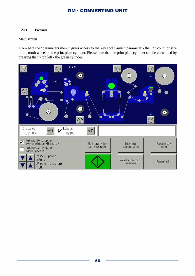
20.1. Pictures
Main screen.
From here the "parameters menu" gives access to the key spot varnish parameter - the "Z" count or size
of the tooth wheel on the print plate cylinder. Please note that the print plate cylinder can be controlled by
pressing the it (top left - the green cylinder).
GM · CONVERTING UNIT
57
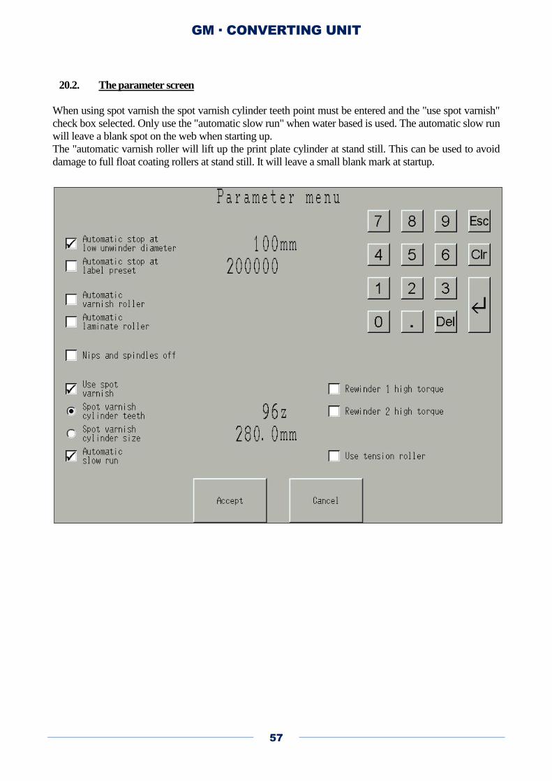
20.2. The parameter screen
When using spot varnish the spot varnish cylinder teeth point must be entered and the "use spot varnish"
check box selected. Only use the "automatic slow run" when water based is used. The automatic slow run
will leave a blank spot on the web when starting up.
The "automatic varnish roller will lift up the print plate cylinder at stand still. This can be used to avoid
damage to full float coating rollers at stand still. It will leave a small blank mark at startup.
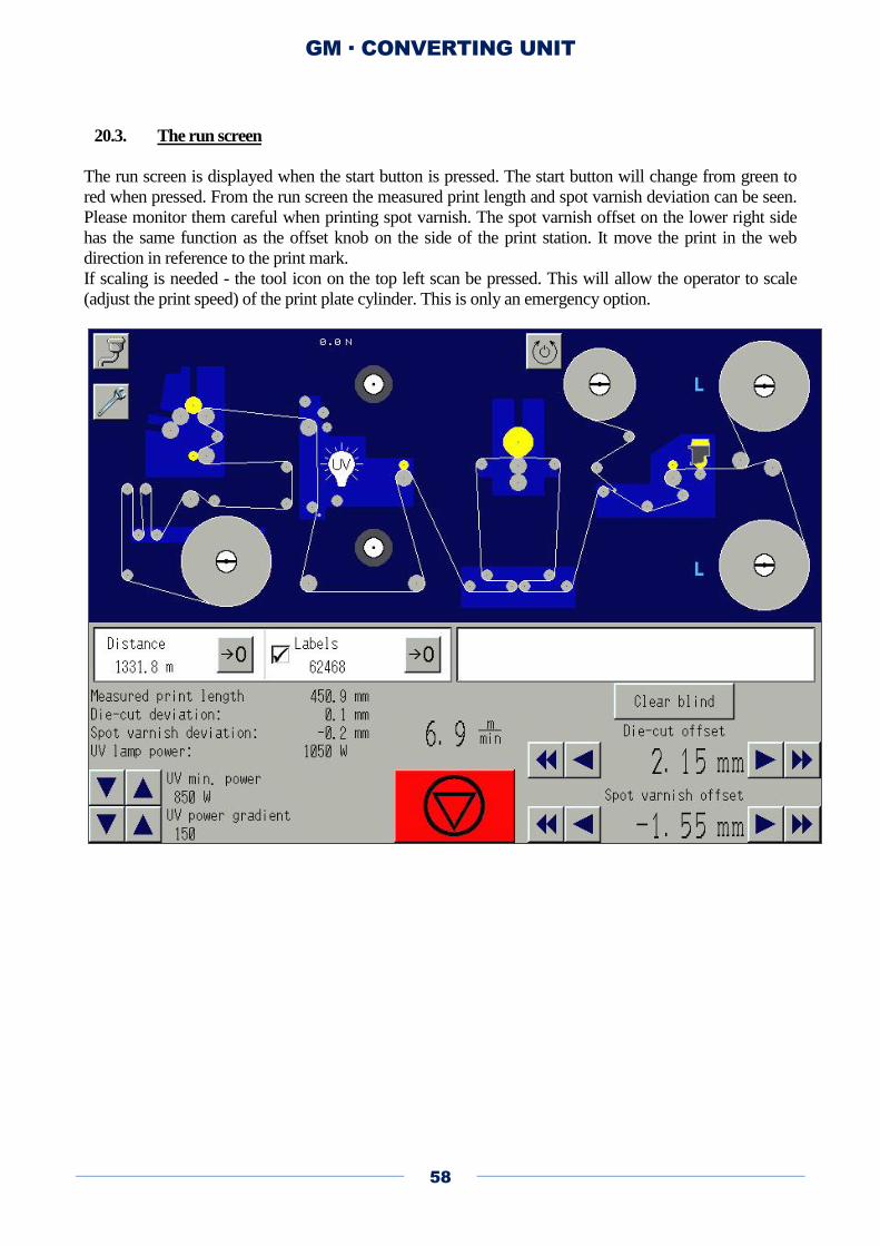
GM · CONVERTING UNIT
58
20.3. The run screen
The run screen is displayed when the start button is pressed. The start button will change from green to
red when pressed. From the run screen the measured print length and spot varnish deviation can be seen.
Please monitor them careful when printing spot varnish. The spot varnish offset on the lower right side
has the same function as the offset knob on the side of the print station. It move the print in the web
direction in reference to the print mark.
If scaling is needed - the tool icon on the top left scan be pressed. This will allow the operator to scale
(adjust the print speed) of the print plate cylinder. This is only an emergency option.

GM · CONVERTING UNIT
59
20.4. Print scaling
When the tool icon is pressed the small dialog box above id displayed. This will alow the operator to
make the spot varnish system go faster or slower. Print quality will be compromised. but it can be used to
get a "bad job" done.

GM · CONVERTING UNIT
60
21. Lamination (Tips and tricks)
If you have fish-eye's in the laminate it is normally a sign of lack of adhesive in some points.
Tricks for for self-adhesive laminates
a) Make sure that the lamination roller is clean and flat. No dirt on sides. Run 3-4 bars pressure.
b) Increase pressure on center nip roller to 5 bars - then it works as a "2nd
lamination roller"
c) Check substrate after 24 hours. Does the fish-eye problem go away over time?
d) Run a clean substrate in the machine (not printed) and check if problem goes away.
e) An additional work-around is to change to a harder nip roller to /VAL001D, which is SH95 compared
to the normal /VAL001C, that is SH65.
Tricks for UV laminates
a) Make sure that the lamination roller is clean and flat. No dirt on sides. Run 3-4 bars pressure.
b) Check that the right side of lamination is used (it is only treated on one side)
c) Check that lamination foil is wider than substrate or anilox has deadband preventing varnish build up
on the sides of the lam roller. If the varnish build up on the sides of lamination roller, then the lamination
roller will "grow big" on the side and fail.
d) Check that anilox volume is high enough - simpel test: run without doctor blade - this will put down
30cm3/m2 of glue - more than needed for all laminates
e) Check substrate compatibility. Simple test. Put down glue without lamination.
Rewind substrate. Run it again and this time putdown glue and lam. If this fix the problem, the substrate
is too open for lamination (must be primed)
f) Check for oil from the press. Turn off oily web and clean all press rollers. Run 1000 feet in press
before starting test. Test if lam works without the oily web turned on.
22. Operator Maintenance Chart
Unit Module Every Activity Tools Remarks
Converter All nips
and rollers
1 day Clean for
varnish and glue
Cloth, alcohol
Converter Anilox/ductor
doctor blade ink
tray
7 days Clean for
varnish/ink
Cloth, uv wash Replace doctor blade
if it’s damaged
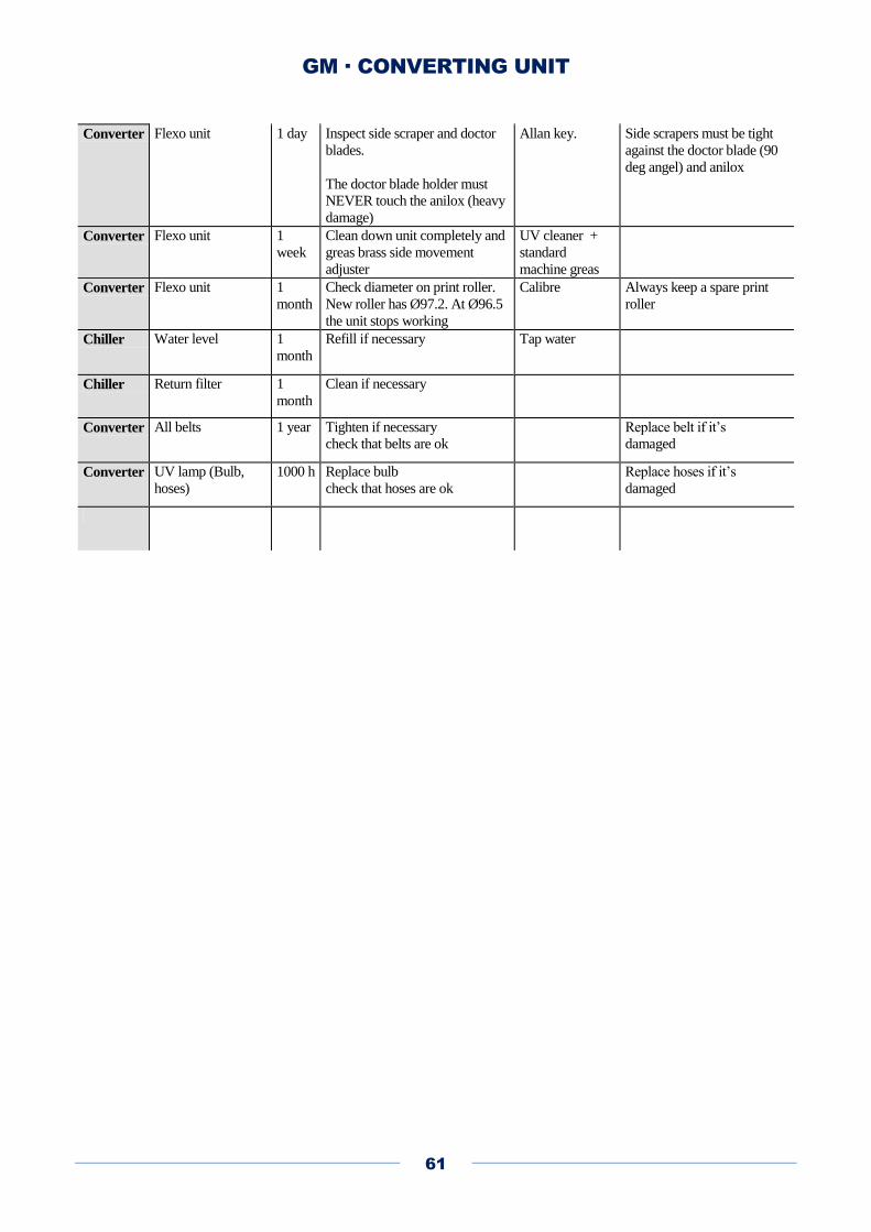
GM · CONVERTING UNIT
61
Converter Flexo unit 1 day Inspect side scraper and doctor
blades.
The doctor blade holder must
NEVER touch the anilox (heavy
damage)
Allan key. Side scrapers must be tight
against the doctor blade (90
deg angel) and anilox
Converter Flexo unit 1
week
Clean down unit completely and
greas brass side movement
adjuster
UV cleaner +
standard
machine greas
Converter Flexo unit 1
month
Check diameter on print roller.
New roller has Ø97.2. At Ø96.5
the unit stops working
Calibre Always keep a spare print
roller
Chiller Water level 1
month
Refill if necessary Tap water
Chiller Return filter 1
month
Clean if necessary
Converter All belts 1 year Tighten if necessary
check that belts are ok
Replace belt if it’s
damaged
Converter UV lamp (Bulb,
hoses)
1000 h Replace bulb
check that hoses are ok
Replace hoses if it’s
damaged
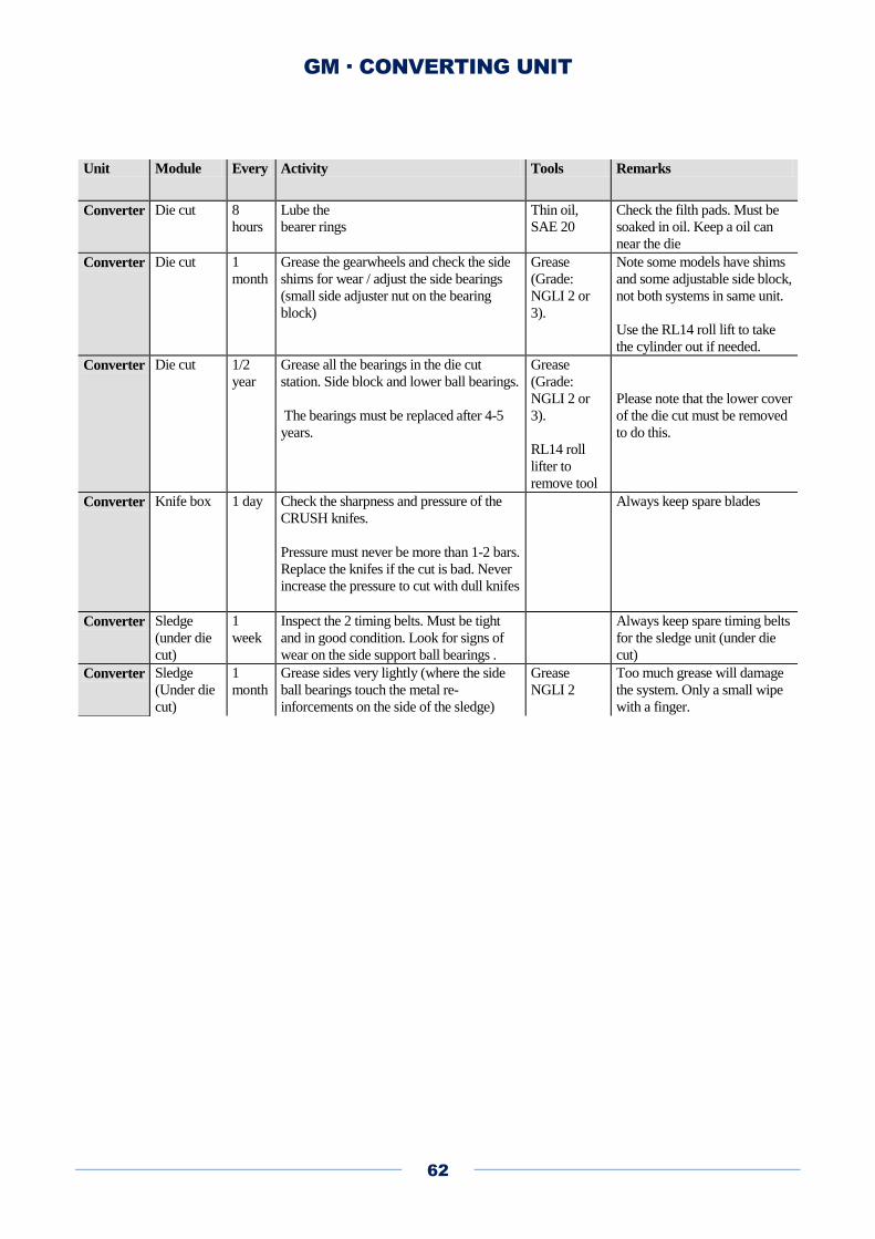
GM · CONVERTING UNIT
62
Unit Module Every Activity Tools Remarks
Converter Die cut 8
hours
Lube the
bearer rings
Thin oil,
SAE 20
Check the filth pads. Must be
soaked in oil. Keep a oil can
near the die
Converter Die cut 1
month
Grease the gearwheels and check the side
shims for wear / adjust the side bearings
(small side adjuster nut on the bearing
block)
Grease
(Grade:
NGLI 2 or
3).
Note some models have shims
and some adjustable side block,
not both systems in same unit.
Use the RL14 roll lift to take
the cylinder out if needed.
Converter Die cut 1/2
year
Grease all the bearings in the die cut
station. Side block and lower ball bearings.
The bearings must be replaced after 4-5
years.
Grease
(Grade:
NGLI 2 or
3).
RL14 roll
lifter to
remove tool
Please note that the lower cover
of the die cut must be removed
to do this.
Converter Knife box 1 day Check the sharpness and pressure of the
CRUSH knifes.
Pressure must never be more than 1-2 bars.
Replace the knifes if the cut is bad. Never
increase the pressure to cut with dull knifes
Always keep spare blades
Converter Sledge
(under die
cut)
1
week
Inspect the 2 timing belts. Must be tight
and in good condition. Look for signs of
wear on the side support ball bearings .
Always keep spare timing belts
for the sledge unit (under die
cut)
Converter Sledge
(Under die
cut)
1
month
Grease sides very lightly (where the side
ball bearings touch the metal re-
inforcements on the side of the sledge)
Grease
NGLI 2
Too much grease will damage
the system. Only a small wipe
with a finger.
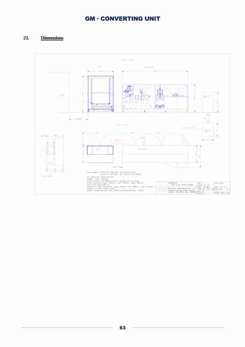
GM · CONVERTING UNIT
63
23. Dimensions
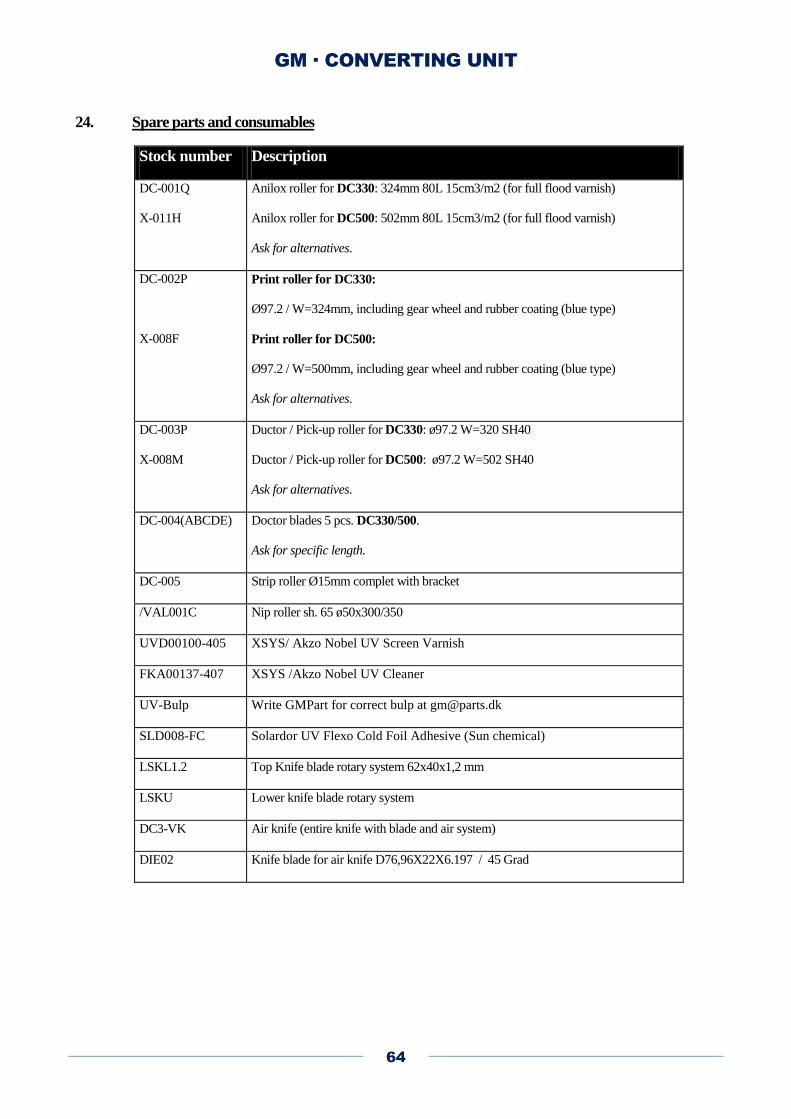
GM · CONVERTING UNIT
64
24. Spare parts and consumables
Stock number Description
DC-001Q
X-011H
Anilox roller for DC330: 324mm 80L 15cm3/m2 (for full flood varnish)
Anilox roller for DC500: 502mm 80L 15cm3/m2 (for full flood varnish)
Ask for alternatives.
DC-002P
X-008F
Print roller for DC330:
Ø97.2 / W=324mm, including gear wheel and rubber coating (blue type)
Print roller for DC500:
Ø97.2 / W=500mm, including gear wheel and rubber coating (blue type)
Ask for alternatives.
DC-003P
X-008M
Ductor / Pick-up roller for DC330: ø97.2 W=320 SH40
Ductor / Pick-up roller for DC500: ø97.2 W=502 SH40
Ask for alternatives.
DC-004(ABCDE) Doctor blades 5 pcs. DC330/500.
Ask for specific length.
DC-005 Strip roller Ø15mm complet with bracket
/VAL001C Nip roller sh. 65 ø50x300/350
UVD00100-405 XSYS/ Akzo Nobel UV Screen Varnish
FKA00137-407 XSYS /Akzo Nobel UV Cleaner
UV-Bulp Write GMPart for correct bulp at [email protected]
SLD008-FC Solardor UV Flexo Cold Foil Adhesive (Sun chemical)
LSKL1.2 Top Knife blade rotary system 62x40x1,2 mm
LSKU Lower knife blade rotary system
DC3-VK Air knife (entire knife with blade and air system)
DIE02 Knife blade for air knife D76,96X22X6.197 / 45 Grad
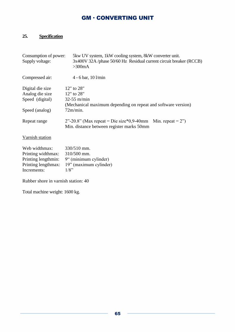
GM · CONVERTING UNIT
65
25. Specification
Consumption of power: 5kw UV system, 1kW cooling system, 8kW converter unit.
Supply voltage: 3x400V 32A /phase 50/60 Hz Residual current circuit breaker (RCCB)
>300mA
Compressed air: 4 - 6 bar, 10 l/min
Digital die size 12" to 28"
Analog die size 12" to 28"
Speed (digital) 32-55 m/min
(Mechanical maximum depending on repeat and software version)
Speed (analog) 72m/min.
Repeat range 2”-20.8” (Max repeat = Die size*0,9-40mm Min. repeat = 2”)
Min. distance between register marks 50mm
Varnish station
Web widthmax: 330/510 mm.
Printing widthmax: 310/500 mm.
Printing lengthmin: 9“ (minimum cylinder)
Printing lengthmax: 19” (maximum cylinder)
Increments: 1/8”
Rubber shore in varnish station: 40
Total machine weight: 1600 kg.
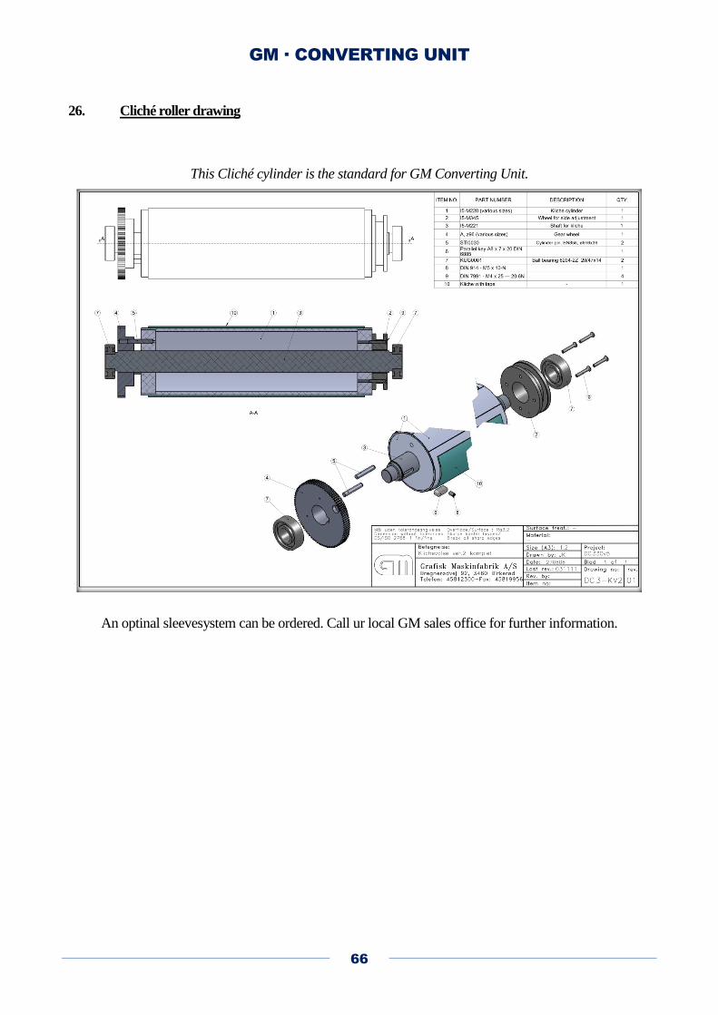
GM · CONVERTING UNIT
66
26. Cliché roller drawing
This Cliché cylinder is the standard for GM Converting Unit.
An optinal sleevesystem can be ordered. Call ur local GM sales office for further information.

GM · CONVERTING UNIT
67

GM · CONVERTING UNIT
68
Specification die cylinder
The gap is the distance between the magnetic cylinder (magnetic zone) and the anvil cylinder. This is
0.48mm on all standard machines with a 25” die cylinder. Please check the order confirmation for the
specific machine to make sure that it was shipped with a standard die tool.
GM · CONVERTING UNIT
69
27. Installation guide
To secure that the installation and training can be carried out without problems and waste of time due to
missing materials or on site preparations for the installation it is very important that the following
preparations and items are ready before the arrival of the machine:
Unloading the machine:
- A fork lift with min. 1000 kg lifting capacity must be ready to get the craters down from the truck.
- Also the fork lift is needed to get the machine down from the craters
- A pallet jack is needed to move and align the machines.
Electric Power:
Power for the machines must be prepared.
- DCOAT and BUFFER 3P+N+PE 400V AC 50Hz 32A
- COOLING UNIT 3P+N+PE 400V AC 50Hz 16A
Air supply:
Min. 6 bar and 20L/min is needed, tube Ø8mm
Cooling Unit (water cooled lamp)
The cooling unit has to be placed at the same level (if possible).
Add Texaco Havoline XLI 7.5% volume to the cooling water. If the Cooling unit is in freezing
surroundings, use XLC 33% volume down tot -20 degree Celsius.
Cooling fan (air cooled lamp)
All new GM converting units delivered with air cooled lamps, are supplied with a ozon emitting bulp.
For the machine to run without an external exhaust system a ozon filter is needed. GM can supply this
ozon filter as an option if needed.
The lifespan for the bulp is aprox.1000 hrs.
Verify that the fan is operating in the correct direction.
If external exhaust is used the capacity must på 800 m3/h. There must be no more than 2m between the
fan and the UV lamp. The tube must not make any sharp turns. Tube diameter is 100mm.
GM · CONVERTING UNIT
70
Starting up the machine:
Test and training can not be carried out unless the following materials are available on site:
- Label material, min. 2000m with a web width of 330mm.
(It is not possible to run a web with a width less than 330mm as the standard print roller is
320mm)
- A printed test job must be prepared and ready, min. 1000m web.
- UV-varnish min. 10 (XSYS Print Solutions / Akzo Nobel UVD 00100-405)
- UV-Wash min 5L (CLU00102-407 or UV Wash2 or Dowanol DPM)
- A die plate and a job for the plate must be prepared and ready to run on the Xeikon DCP
(Drop = 0,48mm see manual for the machine for distortion information )
- Super gloss foil min. 500m is available (width 330mm).
(Pütz Folien GMBH XUC B11 330mm)
- A cliché and a job for spot varnish must be prepared if the machine has spot varnish
( Cliché 1,14mm or 1,7mm double-sided tape 0,38 mm or 0,55mm, Distortion typical. 9,93 for
12” cylinder)
Anilox 10cm3, Glue from X-Sys Cold foil UV-FOILBOND UVH00002, Kurz foil.
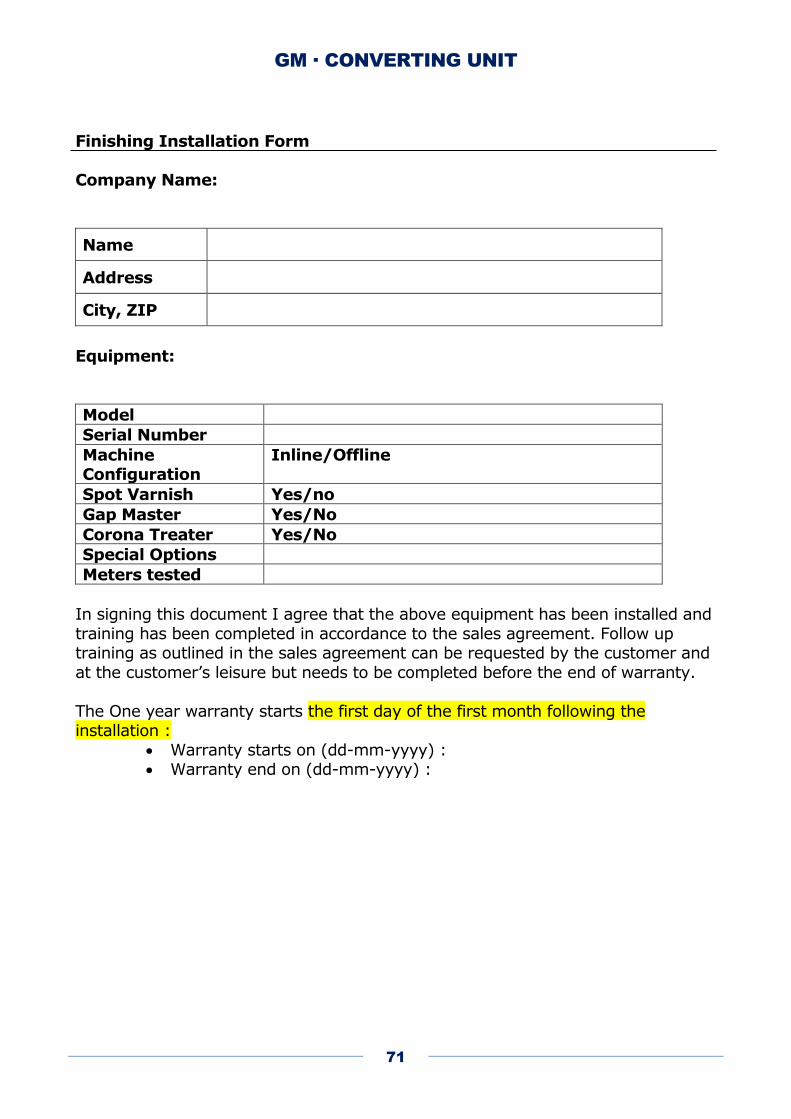
GM · CONVERTING UNIT
71
Finishing Installation Form
Company Name:
Name
Address
City, ZIP
Equipment:
Model
Serial Number
Machine Configuration
Inline/Offline
Spot Varnish Yes/no
Gap Master Yes/No
Corona Treater Yes/No
Special Options
Meters tested
In signing this document I agree that the above equipment has been installed and
training has been completed in accordance to the sales agreement. Follow up training as outlined in the sales agreement can be requested by the customer and
at the customer’s leisure but needs to be completed before the end of warranty.
The One year warranty starts the first day of the first month following the installation :
Warranty starts on (dd-mm-yyyy) : Warranty end on (dd-mm-yyyy) :
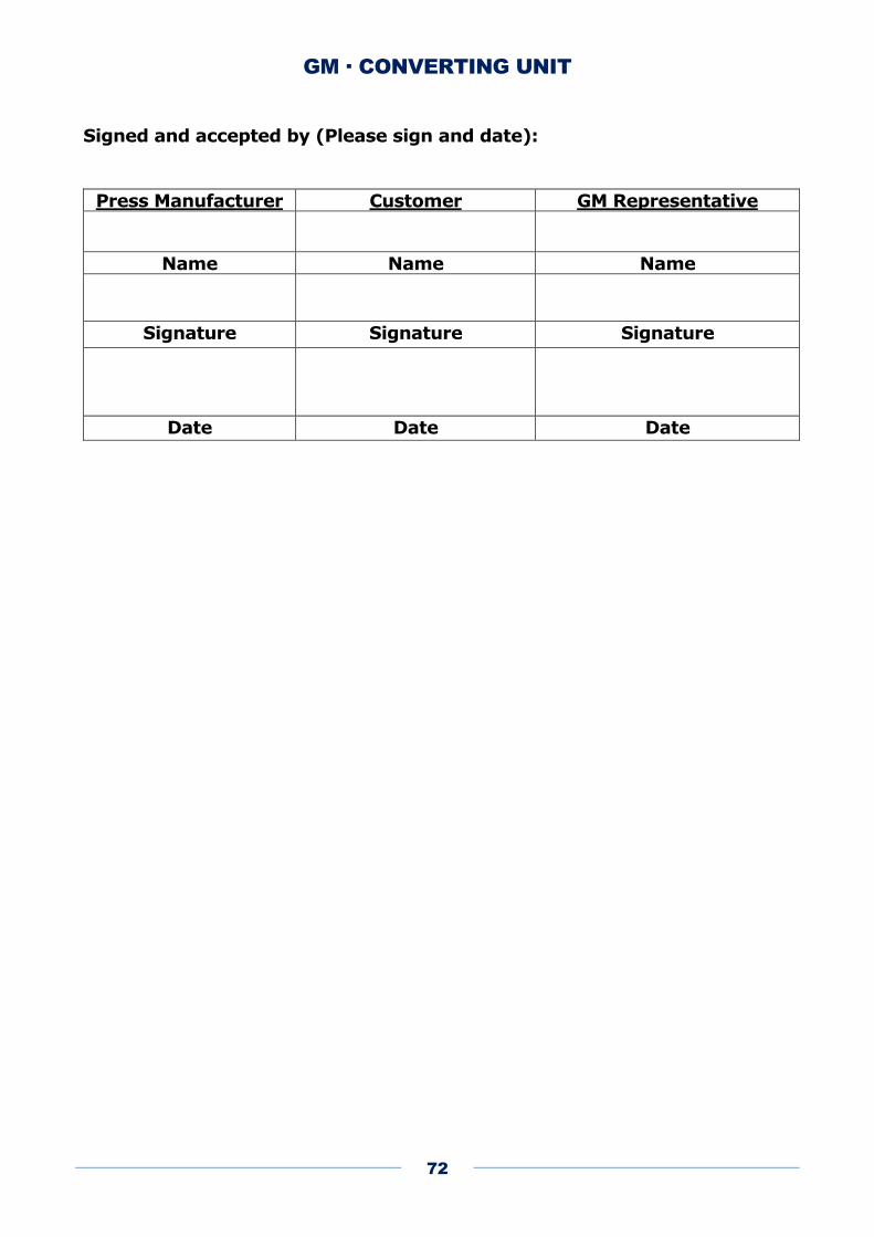
GM · CONVERTING UNIT
72
Signed and accepted by (Please sign and date):
Press Manufacturer Customer GM Representative
Name Name Name
Signature Signature Signature
Date Date Date
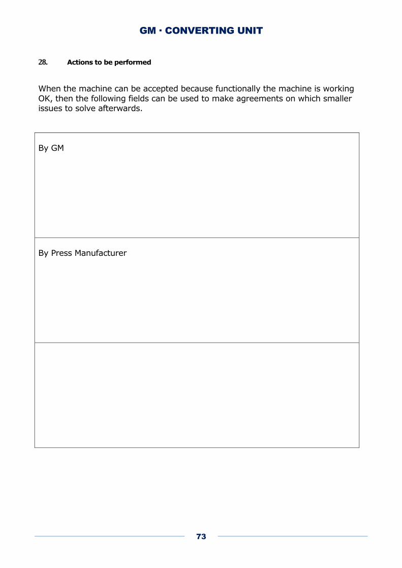
GM · CONVERTING UNIT
73
28. Actions to be performed
When the machine can be accepted because functionally the machine is working
OK, then the following fields can be used to make agreements on which smaller issues to solve afterwards.
By GM
By Press Manufacturer
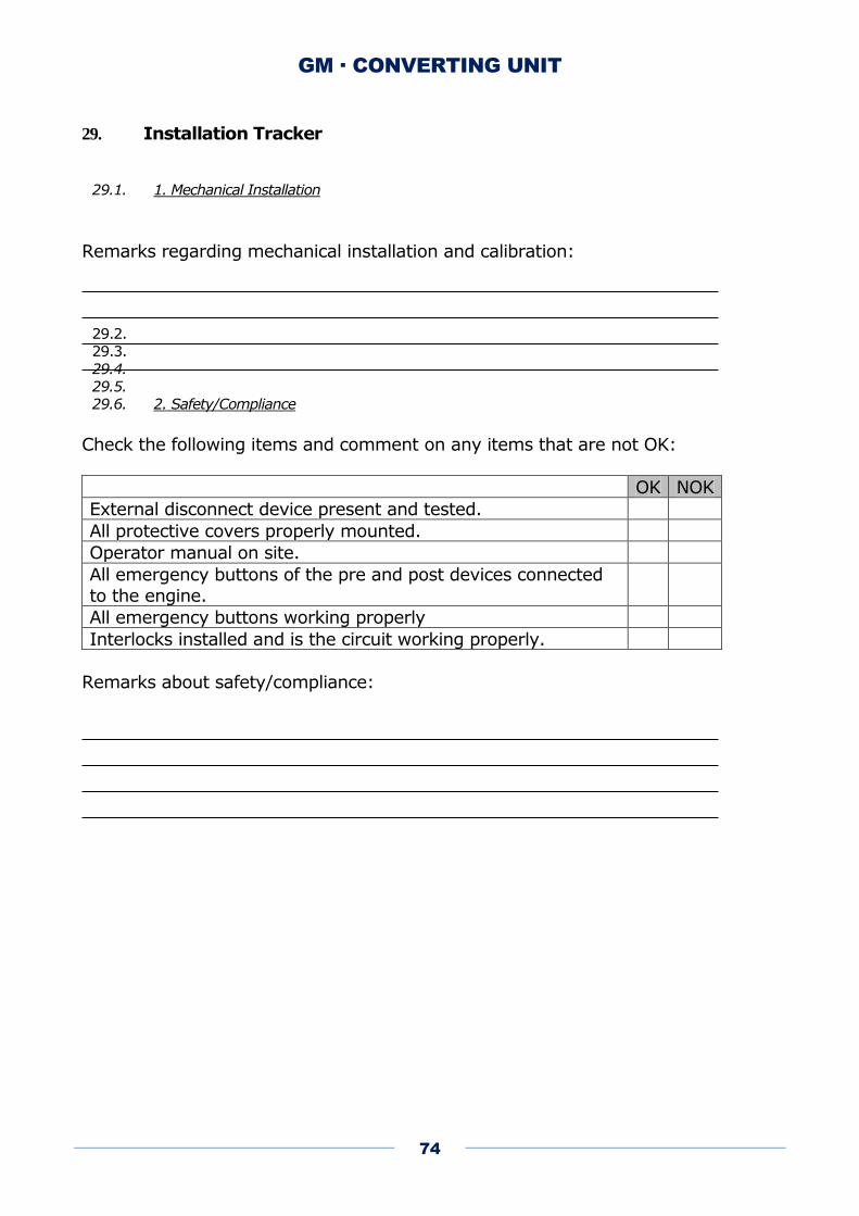
GM · CONVERTING UNIT
74
29. Installation Tracker
29.1. 1. Mechanical Installation
Remarks regarding mechanical installation and calibration:
29.2.
29.3.
29.4.
29.5.
29.6. 2. Safety/Compliance
Check the following items and comment on any items that are not OK:
OK NOK
External disconnect device present and tested.
All protective covers properly mounted.
Operator manual on site.
All emergency buttons of the pre and post devices connected
to the engine.
All emergency buttons working properly
Interlocks installed and is the circuit working properly.
Remarks about safety/compliance:
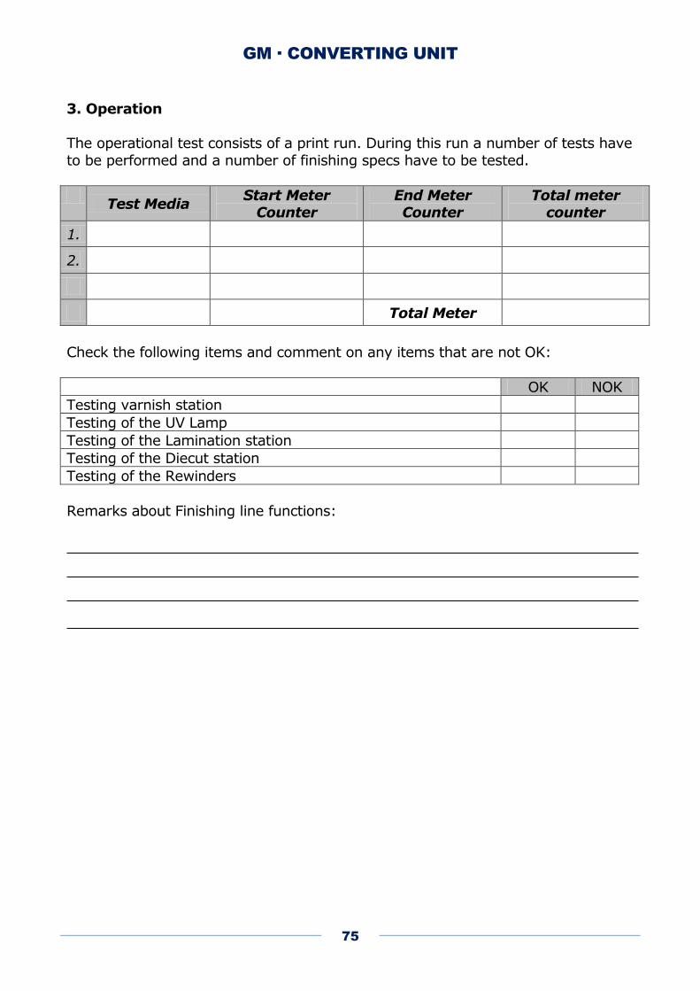
GM · CONVERTING UNIT
75
3. Operation
The operational test consists of a print run. During this run a number of tests have
to be performed and a number of finishing specs have to be tested.
Test Media
Start Meter Counter
End Meter Counter
Total meter counter
1.
2.
Total Meter
Check the following items and comment on any items that are not OK:
OK NOK
Testing varnish station
Testing of the UV Lamp
Testing of the Lamination station
Testing of the Diecut station
Testing of the Rewinders
Remarks about Finishing line functions: