operating manual - atti srl - a.t.t.i. - articoli tecnici ...translation of the original operating...
TRANSCRIPT

PacDrive
Logic Motion Controller
LMC 101/201 C11.2012
Operating Manual(Translation of the original Operating Manual)
EIO
0000
0015
01.0
0

The information provided in this documentation contains general descriptions and/ortechnical characteristics of the performance of the products contained herein. Thisdocumentation is not intended as a substitute for and is not to be used for determiningsuitability or reliability of these products for specific user applications. It is the duty ofany such user or integrator to perform the appropriate and complete risk analysis,evaluation and testing of the products with respect to the relevant specific applicationor use thereof. Neither Schneider Electric nor any of its affiliates or subsidiaries shallbe responsible or liable for misuse of the information contained herein. If you have anysuggestions for improvements or amendments or have found errors in this publication,please notify us.No part of this document may be reproduced in any form or by any means, electronicor mechanical, including photocopying, without express written permission of Schneid‐er Electric.All pertinent state, regional, and local safety regulations must be observed when in‐stalling and using this product. For reasons of safety and to help ensure compliancewith documented system data, only the manufacturer should perform repairs to com‐ponents.When devices are used for applications with technical safety requirements, the rele‐vant instructions must be followed.Failure to use Schneider Electric software or approved software with our hardwareproducts may result in injury, harm, or improper operating results.Failure to observe this information can result in injury or equipment damage.© 2012 Schneider Electric. All rights reserved.
Imprint
Page 2 PacDrive Logic Motion Controller LMC 101/201 C Schneider Electric EIO
0000
0015
01.0
0

Contents
1 About this manual 61.1 Introduction ............................................................................................................... 61.2 Symbols, designator and display format of safety messages .................................. 7
2 Safety information 92.1 Proper use ................................................................................................................ 92.2 Qualification of Personnel ...................................................................................... 102.3 Residual risks ......................................................................................................... 112.3.1 Electrical parts ........................................................................................................ 112.3.2 Assembly and handling .......................................................................................... 112.3.3 Hazardous movements .......................................................................................... 122.3.4 PELV circuits .......................................................................................................... 13
3 System overview 143.1 Logic Motion Controller .......................................................................................... 143.2 ILM62 system ......................................................................................................... 153.2.1 ILM62DB Distribution Box ...................................................................................... 153.2.2 ILM62 motor ........................................................................................................... 163.3 Lexium LXM52 ....................................................................................................... 163.4 Lexium LXM62 ....................................................................................................... 173.5 SH3 Servo motor .................................................................................................... 173.6 TM5 System ........................................................................................................... 183.7 Type code ............................................................................................................... 193.8 Nameplate descriptions .......................................................................................... 20
4 Indicators and control elements 214.1 Indicators of the controller ...................................................................................... 214.1.1 Liquid Crystal Display (LCD) .................................................................................. 224.1.2 State LED ............................................................................................................... 254.1.3 PRG LED ................................................................................................................ 254.1.4 S3 LED ................................................................................................................... 254.1.5 CAN LED ................................................................................................................ 264.1.6 TM5 LED ................................................................................................................ 264.1.7 Status LED Ethernet ............................................................................................... 274.1.8 Status-LED SERCOS III ......................................................................................... 274.2 Operating elements of the controller ...................................................................... 284.2.1 Menu buttons .......................................................................................................... 28
Contents
Schneider Electric PacDrive Logic Motion Controller LMC 101/201 C Page 3EIO
0000
0015
01.0
0

4.2.2 SD card-slot ............................................................................................................ 284.2.3 USB connection ..................................................................................................... 30
5 Installation and maintenance 315.1 Commissioning ....................................................................................................... 315.1.1 Preparing commissioning ....................................................................................... 315.1.2 Wiring of the controller ........................................................................................... 325.1.3 Preparing the control cabinet ................................................................................. 335.1.4 Completion of commissioning ................................................................................ 345.1.5 Performing the function test ................................................................................... 355.2 Configuration, homing and programming ............................................................... 355.3 Diagnostics ............................................................................................................. 365.3.1 Connection to controller ......................................................................................... 365.3.2 Check the flash disk of the controller - LMCx01 ..................................................... 385.3.3 Example of a diagnostic message .......................................................................... 385.4 Electromagnetic Compatibility, EMC ...................................................................... 395.5 Maintenance, repair, cleaning ................................................................................ 415.5.1 Repair ..................................................................................................................... 415.5.2 Cleaning ................................................................................................................. 415.5.3 Battery, Real-time clock ......................................................................................... 415.6 Spare part inventory ............................................................................................... 425.7 Device-, parts- or cable exchange .......................................................................... 425.7.1 Device replacement ................................................................................................ 425.8 Fast Device Replacement ...................................................................................... 445.8.1 Introduction ............................................................................................................. 445.8.2 Use ......................................................................................................................... 445.8.3 Controller display .................................................................................................... 465.8.4 Application .............................................................................................................. 48
6 Technical data 536.1 Ambient conditions ................................................................................................. 536.2 Standards and regulations ..................................................................................... 546.3 Mechanical and electrical data ............................................................................... 546.4 Electrical connections ............................................................................................. 566.4.1 Connection overview controller .............................................................................. 566.4.2 Connection details controller .................................................................................. 596.5 Dimensions ............................................................................................................. 64
7 Optional module 657.1 Communication Module Realtime Ethernet ............................................................ 657.1.1 General ................................................................................................................... 657.1.2 Mechanical installation ........................................................................................... 667.1.3 Electrical connections ............................................................................................. 687.2 Communication Module PROFIBUS DP ................................................................ 75
Contents
Page 4 PacDrive Logic Motion Controller LMC 101/201 C Schneider Electric EIO
0000
0015
01.0
0

7.2.1 General ................................................................................................................... 757.2.2 Mechanical installation ........................................................................................... 767.2.3 Electrical connections ............................................................................................. 78
8 Appendix 808.1 Contact addresses ................................................................................................. 808.2 Product training courses ......................................................................................... 808.3 Disposal .................................................................................................................. 808.4 Units and conversion tables ................................................................................... 818.4.1 Length .................................................................................................................... 818.4.2 Mass ....................................................................................................................... 818.4.3 Force ...................................................................................................................... 818.4.4 Power ..................................................................................................................... 818.4.5 Rotation .................................................................................................................. 818.4.6 Torque .................................................................................................................... 828.4.7 Moment of inertia .................................................................................................... 828.4.8 Temperature ........................................................................................................... 828.4.9 Conductor cross-section ......................................................................................... 82
Contents
Schneider Electric PacDrive Logic Motion Controller LMC 101/201 C Page 5EIO
0000
0015
01.0
0
1 About this manual
1.1 Introduction
Read and understand the material contained in this manual before you work on thecontroller for the first time. Take particular note of the safety information (see 2.3 Re‐sidual risks). As described in section 2.2, only those persons who meet the "Selectionand qualification of employees" are allowed to work at the controller.A copy of this manual must be available for personnel who work at the controller.This manual is supposed to help you use the capabilities of the controller safely andproperly.Follow the instructions within this manual to:
• avoid risks• reduce repair costs and downtime of the controller• increase the service life of of the controller• increase reliability of the controller.
1 About this manual
Page 6 PacDrive Logic Motion Controller LMC 101/201 C Schneider Electric EIO
0000
0015
01.0
0

1.2 Symbols, designator and display format of safety messages
Important InformationNOTE The following special messages may appear throughout this documentation or on the
equipment to warn of potential hazards or to call attention to information that clarifiesor simplifies a procedure.
The addition of this symbol to a Danger or Warning safety label indicates that an electricalhazard exists, which will result in personal injury if the instructions are not followed.
This is the safety alert symbol. It is used to warn the user of potential personal injuryhazards. Obey all safety messages that follow this symbol to avoid possible injury ordeath.
DANGERDANGER indicates an imminently hazardous situation which, if not avoided, will result in deathor serious injury.
WARNINGWARNING indicates a potentially hazardous situation which, if not avoided, can result in deathor serious injury.
CAUTIONCAUTION indicates a potentially hazardous situation which, if not avoided, can result in minoror moderate injury.
NOTICENOTICE, used without the safety alert symbol, indicates a potentially hazardous situationwhich, if not avoided, can result in equipment damage.
1.2 Symbols, designator and display format of safety messages
Schneider Electric PacDrive Logic Motion Controller LMC 101/201 C Page 7EIO
0000
0015
01.0
0
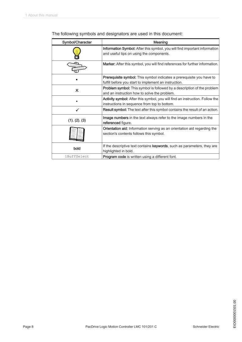
The following symbols and designators are used in this document:
Symbol/Character MeaningInformation Symbol: After this symbol, you will find important informationand useful tips on using the components.
Marker: After this symbol, you will find references for further information.
Prerequisite symbol: This symbol indicates a prerequisite you have tofulfill before you start to implement an instruction.Problem symbol: This symbol is followed by a description of the problemand an instruction how to solve the problem.
► Activity symbol: After this symbol, you will find an instruction. Follow theinstructions in sequence from top to bottom.
ü Result symbol: The text after this symbol contains the result of an action.
(1), (2), (3) Image numbers in the text always refer to the image numbers in thereferenced figure.Orientation aid: Information serving as an orientation aid regarding thesection's contents follows this symbol.
bold If the descriptive text contains keywords, such as parameters, they arehighlighted in bold.
lBuffSelect Program code is written using a different font.
1 About this manual
Page 8 PacDrive Logic Motion Controller LMC 101/201 C Schneider Electric EIO
0000
0015
01.0
0

2 Safety information
This section contains information regarding working with the controller. Qualified per‐sonnel working on the controller must read and observe this information. The controlleris conform to recognized technical safety regulations.
2.1 Proper use
The controller must only be installed in a closed electrical equipment (for example,control cabinet).
Provide forprotectivemeasures
Before installing the device, provide for appropriate protective devices in compliancewith local and national standards. Do not commission components without suitableprotective devices. After installation, commissioning, or repair, test the protective de‐vices used.Perform a risk evaluation concerning the specific use before operating the product andtake appropriate security measures.If circumstances occur that affect the safety or cause changes during the operatingperformance of the controller, then the controller has to be shutdown immediately andyou should contact your Schneider Electric contact person.
Use original-equipment
only
Use only the accessories and mounting parts specified in the documentation and nothird-party devices or components that have not been expressly approved by Schneid‐er Electric. Do not change the controller inappropriately.The components must not be used in the following environments:
Forbiddenenvironments
• In hazardous (explosive) atmospheres• In mobile, movable or floating systems• In life support systems• In domestic appliances• underground
Installationand operating
conditions
Only use the components in accordance with the installation and operating conditionsdescribed in this documentation. The operating conditions at the installation locationmust be inspected and maintained in accordance with the required technical data(performance data and ambient conditions). Commissioning is prohibited until theusable machine or system in which the controller is installed meets all requirementsof EC guidelines 2006/42/EC (machine guideline).In addition, the following standards, directives and regulations are to be observed:
• EN ISO 13849-1:2008 Safety of machinery - Safety-related parts of control systems- Part 1: General principles for design
• EN 60204-1:2006 Safety of machinery - Electrical equipment of machines - Part 1:General requirements
• EN ISO 12100-1:2003 - Safety of machines - Basic terms, general principles fordesign - Part 1: Basic terminology, methodology
• EN ISO 12100-2:2003 - Safety of machines - Basic terms, general principles ofdesign - Part 2: Technical guidelines
• EN 50178: 1997 - Electronic equipment for use in power installations
• EN 61800-3:2004 Adjustable speed electrical power drive systems - Part 3: EMCrequirements and specific test methods
2.1 Proper use
Schneider Electric PacDrive Logic Motion Controller LMC 101/201 C Page 9EIO
0000
0015
01.0
0

• EN 61800-5-1:2007 Adjustable speed electrical power drive systems - Part 5-1:Safety requirements - Electrical, thermal and energy
• EN 61131-2:2007 Programmable controllers - Part 2: Equipment requirements andtests
• The generally applicable local and national safety and accident prevention regu‐lations.
• The rules and regulations on accident prevention and environmental protection thatapply in the country where the product is used.
2.2 Qualification of Personnel
Target audi‐ence
for this manual
Electrical equipment must be installed, operated, serviced, and maintained only byqualified personnel. No responsibility is assumed by Schneider Electric for any con‐sequences arising out of the use of this material.
Qualified per‐son
A qualified person is one who has skills and knowledge related to the construction andoperation of electrical equipment and the installation, and has received safety trainingto recognize and avoid the hazards involved.The qualified personnel must be able to detect possible hazards that may arise fromparameterization, changing parameter values and generally from mechanical, electri‐cal or electronic equipment. The qualified personnel must be familiar with the stand‐ards, provisions and regulations for the prevention of industrial accidents, which theymust observe when working on the drive system.
2 Safety information
Page 10 PacDrive Logic Motion Controller LMC 101/201 C Schneider Electric EIO
0000
0015
01.0
0
2.3 Residual risks
Health risks arising from the controller have been reduced. However a residual riskremains, since the controller works with electrical voltage and electrical currents.
If activities involve residual risks, a safety message is made at the appropriate points.This includes potential hazard(s) that may arise, their possible consequences, anddescribes preventive measures to avoid the hazard(s). The following types of warningsconcerning residual risks which cannot be assigned to a specific handling. The struc‐ture of a warning instruction is identical to that of a safety label.
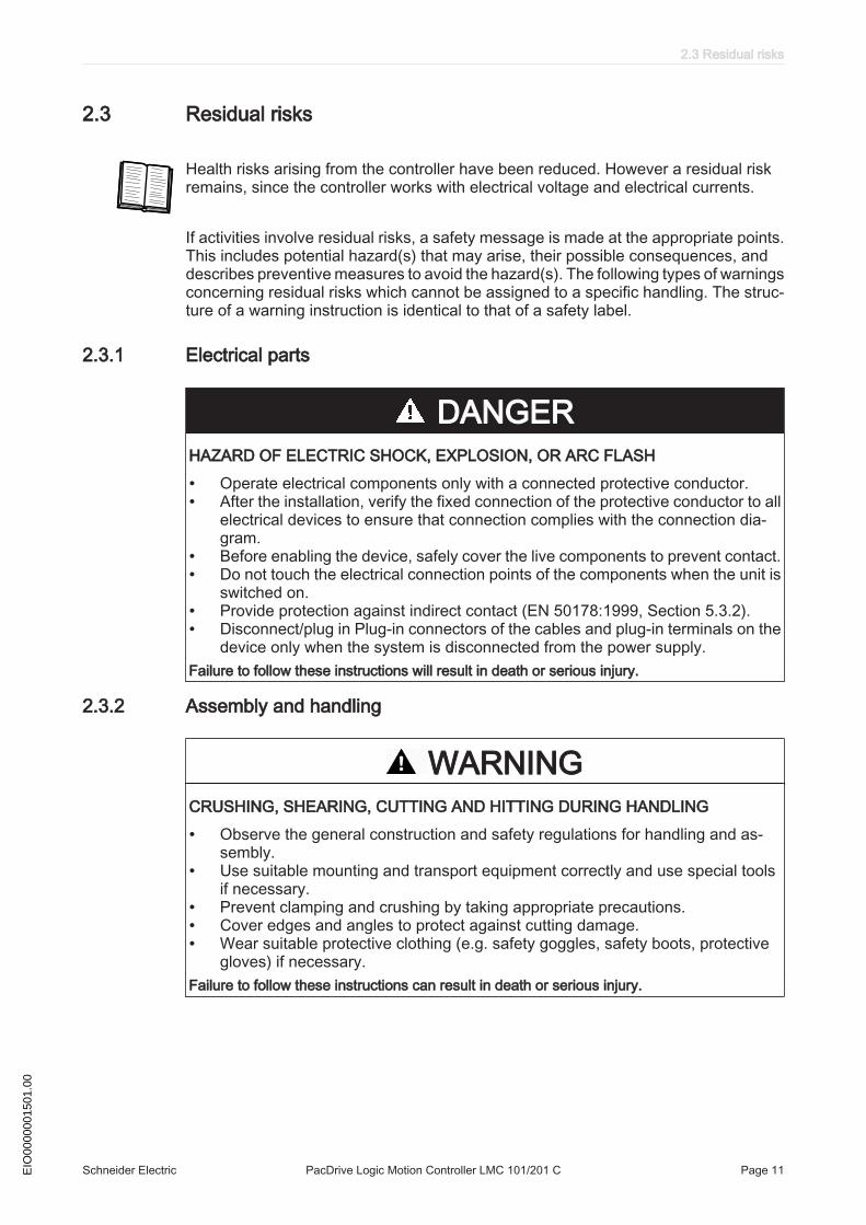
2.3.1 Electrical parts
DANGERHAZARD OF ELECTRIC SHOCK, EXPLOSION, OR ARC FLASH
• Operate electrical components only with a connected protective conductor.• After the installation, verify the fixed connection of the protective conductor to all
electrical devices to ensure that connection complies with the connection dia‐gram.
• Before enabling the device, safely cover the live components to prevent contact.• Do not touch the electrical connection points of the components when the unit is
switched on.• Provide protection against indirect contact (EN 50178:1999, Section 5.3.2).• Disconnect/plug in Plug-in connectors of the cables and plug-in terminals on the
device only when the system is disconnected from the power supply.Failure to follow these instructions will result in death or serious injury.
2.3.2 Assembly and handling
WARNINGCRUSHING, SHEARING, CUTTING AND HITTING DURING HANDLING
• Observe the general construction and safety regulations for handling and as‐sembly.
• Use suitable mounting and transport equipment correctly and use special toolsif necessary.
• Prevent clamping and crushing by taking appropriate precautions.• Cover edges and angles to protect against cutting damage.• Wear suitable protective clothing (e.g. safety goggles, safety boots, protective
gloves) if necessary.Failure to follow these instructions can result in death or serious injury.
2.3 Residual risks
Schneider Electric PacDrive Logic Motion Controller LMC 101/201 C Page 11EIO
0000
0015
01.0
0

2.3.3 Hazardous movements
There can be different causes of hazardous movements:
• Missing or incorrect homing of the drive• Wiring or cabling errors• Errors in the application program• Potential component errors• Potential error in the measured value and signal transmitter
Provide for personal safety by primary equipment monitoring or measures. Do not relyonly on the internal monitoring of the drive components. Adapt the monitoring or otherarrangements and measures to the specific conditions of the installation in accordancewith a risk and error analysis carried out by the system manufacturer.
DANGERMISSING PROTECTIVE DEVICE OR INCORRECT PROTECTION
• Prevent entry to a hazard area, for example with protective fencing, mesh guards,protective coverings, or light barriers.
• Dimension the protective devices properly and do not remove them.• Do not carry out any changes that can invalidate the protection device.• Before accessing the drives or entering the hazard area, bring the drives to a
stop.• Protect existing work stations and operating terminals against unauthorized op‐
eration.• Position EMERGENCY STOP switches so that they are easily accessible and
can be quickly reached.• Check the functionality of EMERGENCY STOP equipment before start-up and
during maintenance periods.• Prevent unintentional start-up by disconnecting the power connection of the drive
using the EMERGENCY STOP circuit or using an appropriate lock-out tag-outsequence.
• Check the system and installation before the initial start-up for possible glitchesin all general purposes.
• Avoid operating high-frequency, remote control, and radio devices close to thesystem electronics and their feed lines. If necessary, perform a special EMCcheck of the system.
Failure to follow these instructions will result in death or serious injury.
2 Safety information
Page 12 PacDrive Logic Motion Controller LMC 101/201 C Schneider Electric EIO
0000
0015
01.0
0
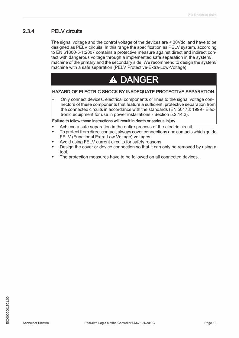
2.3.4 PELV circuits
The signal voltage and the control voltage of the devices are < 30Vdc and have to bedesigned as PELV circuits. In this range the specification as PELV system, accordingto EN 61800-5-1:2007 contains a protective measure against direct and indirect con‐tact with dangerous voltage through a implemented safe separation in the system/machine of the primary and the secondary side. We recommend to design the system/machine with a safe separation (PELV Protective-Extra-Low-Voltage).
DANGERHAZARD OF ELECTRIC SHOCK BY INADEQUATE PROTECTIVE SEPARATION
• Only connect devices, electrical components or lines to the signal voltage con‐nectors of these components that feature a sufficient, protective separation fromthe connected circuits in accordance with the standards (EN 50178: 1999 - Elec‐tronic equipment for use in power installations - Section 5.2.14.2).
Failure to follow these instructions will result in death or serious injury.▶ Achieve a safe separation in the entire process of the electric circuit.▶ To protect from direct contact, always cover connections and contacts which guide
FELV (Functional Extra Low Voltage) voltages.▶ Avoid using FELV current circuits for safety reasons.▶ Design the cover or device connection so that it can only be removed by using a
tool.▶ The protection measures have to be followed on all connected devices.
2.3 Residual risks
Schneider Electric PacDrive Logic Motion Controller LMC 101/201 C Page 13EIO
0000
0015
01.0
0
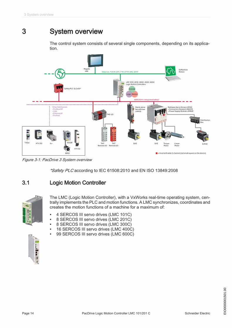
3 System overviewThe control system consists of several single components, depending on its applica‐tion.
Ethernet, TCP/IP, OPC, FTP, HTTP, SMS, SMTP
SERCOS III + Integrated Safety*
Magelis
HMI
LMC 101C, 201C, 300C, 400C, 600C
Logic Motion Controllers
SoMachine
Motion
IT/COM
Logic Motion
TM7
Remote I/O
TM7
Remote I/O
TM5 I/O
Multiaxes Servo Drives LXM 62
+ Power Supply Module LXM62P
Stand-alone
ServoDrives
LXM 52
Distribution
Box
ILM 62SH3 euqroT H3S
Motor
Linear
Motor
Other field busses:
• Profibus DP
• CAN
• Ethernet/IP
• Profinet
Safety PLC SLCx00*
ILx SD328
BRS3
TeSys ATV 312
ATV 32
= InverterEnable 2-channel (red small square on the device)
+ Connection Module ILM62CM
Figure 3-1: PacDrive 3 System overview
*Safety PLC according to IEC 61508:2010 and EN ISO 13849:2008
3.1 Logic Motion Controller
The LMC (Logic Motion Controller), with a VxWorks real-time operating system, cen‐trally implements the PLC and motion functions. A LMC synchronizes, coordinates andcreates the motion functions of a machine for a maximum of:
• 4 SERCOS III servo drives (LMC 101C)• 8 SERCOS III servo drives (LMC 201C)• 8 SERCOS III servo drives (LMC 300C)• 16 SERCOS III servo drives (LMC 400C)• 99 SERCOS III servo drives (LMC 600C)
3 System overview
Page 14 PacDrive Logic Motion Controller LMC 101/201 C Schneider Electric EIO
0000
0015
01.0
0

3.2 ILM62 system
The modular servo drive system ILM62 is designed for the operation of servo drivesin a multi-axes system.The power electronic components of the ILM62 are fitted inside the control cabinet.
Using a common DC bus, the central power supply unit Power Supply Module LXM62Psupplies the connected servo converters with the power required.
The Connection Module ILM62CM supplies the ILM62 motors with DC voltage fromthe DC bus via a hybrid cable.
The ILM62 simplifies the wiring of the devices in relation to the initial start-up and inservice cases. This also applies to the cable connection of the enclosed devices to thefield. All the connectors that can be connected from the outside (power input, DC bus,24Vdc supply, SERCOS, Ready and Inverter Enable) are designed such, that a fastand simple configuration without tools can be realized on the device.
3.2.1 ILM62DB Distribution Box
The Distribution Box ILM62DB is the link between Connection Module ILM62CM andILM62 motor. Depending on the number of drives, 1 to 4 ILM62 motors can be con‐nected. When operating more than 4 drives, simply expand the system using one ormore Distribution Box ILM62DB.
The highlights
• 1...4 connections for ILM62 motors or further Distribution Box ILM62DB• easy wiring using pre-assembled hybrid cables• easy to expand
3.2 ILM62 system
Schneider Electric PacDrive Logic Motion Controller LMC 101/201 C Page 15EIO
0000
0015
01.0
0
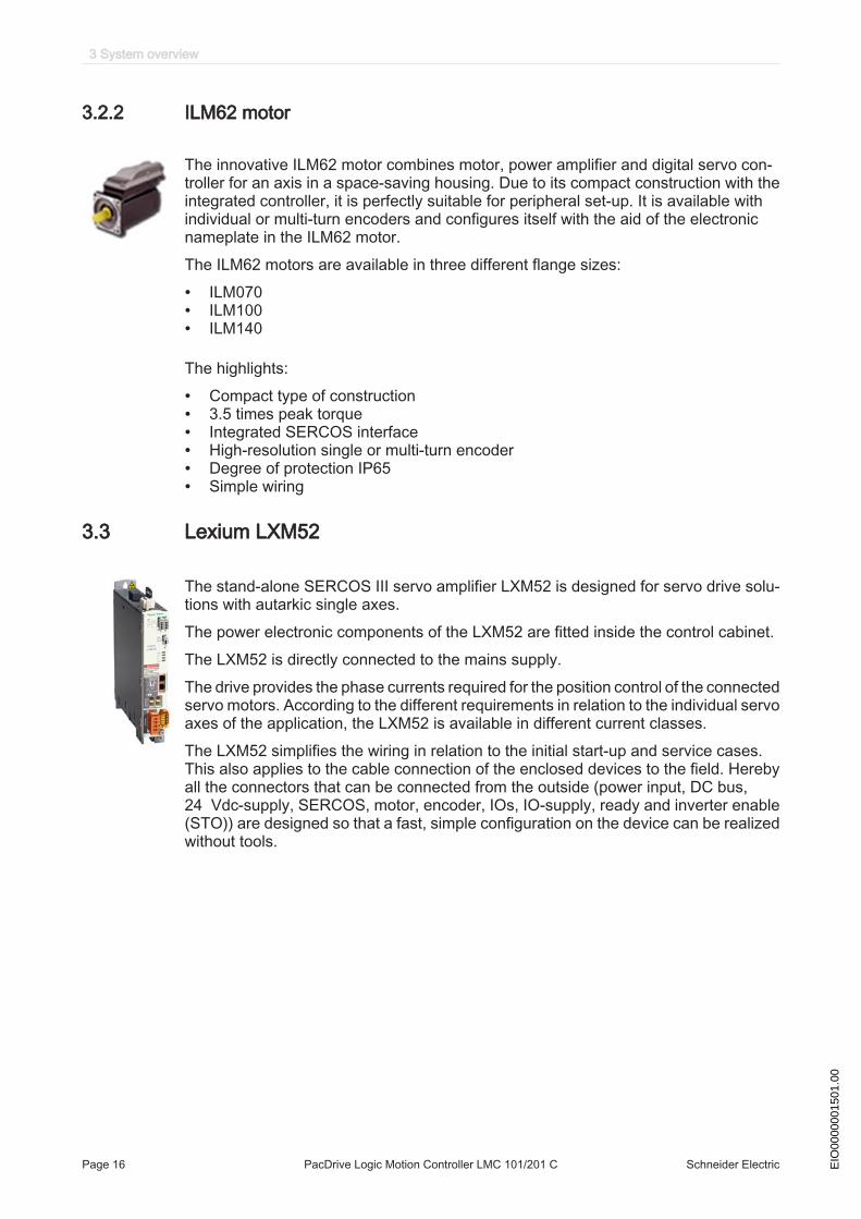
3.2.2 ILM62 motor
The innovative ILM62 motor combines motor, power amplifier and digital servo con‐troller for an axis in a space-saving housing. Due to its compact construction with theintegrated controller, it is perfectly suitable for peripheral set-up. It is available withindividual or multi-turn encoders and configures itself with the aid of the electronicnameplate in the ILM62 motor.The ILM62 motors are available in three different flange sizes:
• ILM070• ILM100• ILM140
The highlights:
• Compact type of construction• 3.5 times peak torque• Integrated SERCOS interface• High-resolution single or multi-turn encoder• Degree of protection IP65• Simple wiring
3.3 Lexium LXM52
The stand-alone SERCOS III servo amplifier LXM52 is designed for servo drive solu‐tions with autarkic single axes.The power electronic components of the LXM52 are fitted inside the control cabinet.The LXM52 is directly connected to the mains supply.The drive provides the phase currents required for the position control of the connectedservo motors. According to the different requirements in relation to the individual servoaxes of the application, the LXM52 is available in different current classes.The LXM52 simplifies the wiring in relation to the initial start-up and service cases.This also applies to the cable connection of the enclosed devices to the field. Herebyall the connectors that can be connected from the outside (power input, DC bus,24 Vdc-supply, SERCOS, motor, encoder, IOs, IO-supply, ready and inverter enable(STO)) are designed so that a fast, simple configuration on the device can be realizedwithout tools.
3 System overview
Page 16 PacDrive Logic Motion Controller LMC 101/201 C Schneider Electric EIO
0000
0015
01.0
0
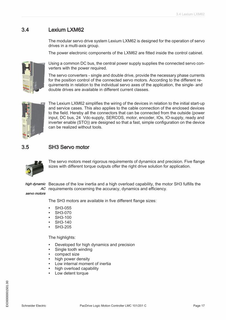
3.4 Lexium LXM62
The modular servo drive system Lexium LXM62 is designed for the operation of servodrives in a multi-axis group.The power electronic components of the LXM62 are fitted inside the control cabinet.
Using a common DC bus, the central power supply supplies the connected servo con‐verters with the power required.The servo converters - single and double drive, provide the necessary phase currentsfor the position control of the connected servo motors. According to the different re‐quirements in relation to the individual servo axes of the application, the single- anddouble drives are available in different current classes.
The Lexium LXM62 simplifies the wiring of the devices in relation to the initial start-upand service cases. This also applies to the cable connection of the enclosed devicesto the field. Hereby all the connectors that can be connected from the outside (powerinput, DC bus, 24 Vdc-supply, SERCOS, motor, encoder, IOs, IO-supply, ready andinverter enable (STO)) are designed so that a fast, simple configuration on the devicecan be realized without tools.
3.5 SH3 Servo motor
The servo motors meet rigorous requirements of dynamics and precision. Five flangesizes with different torque outputs offer the right drive solution for application.
high dynamicAC
servo motors
Because of the low inertia and a high overload capability, the motor SH3 fulfills therequirements concerning the accuracy, dynamics and efficiency.
The SH3 motors are available in five different flange sizes:
• SH3-055• SH3-070• SH3-100• SH3-140• SH3-205
The highlights:
• Developed for high dynamics and precision• Single tooth winding• compact size• high power density• Low internal moment of inertia• high overload capability• Low detent torque
3.4 Lexium LXM62
Schneider Electric PacDrive Logic Motion Controller LMC 101/201 C Page 17EIO
0000
0015
01.0
0

3.6 TM5 System
The direct connection of the TM5 system to the LMC 101/201 C is not possible. TheTM5 system can be connected via the SERCOS III bus interface.
3 System overview
Page 18 PacDrive Logic Motion Controller LMC 101/201 C Schneider Electric EIO
0000
0015
01.0
0

3.7 Type code
Figure 3-2: Type code LMC 101/201C
3.7 Type code
Schneider Electric PacDrive Logic Motion Controller LMC 101/201 C Page 19EIO
0000
0015
01.0
0
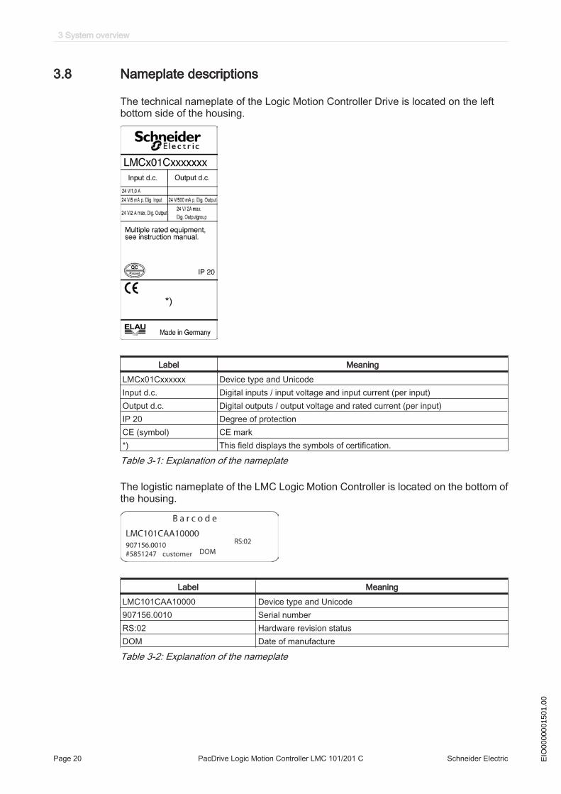
3.8 Nameplate descriptions
The technical nameplate of the Logic Motion Controller Drive is located on the leftbottom side of the housing.
Label MeaningLMCx01Cxxxxxx Device type and UnicodeInput d.c. Digital inputs / input voltage and input current (per input)Output d.c. Digital outputs / output voltage and rated current (per input)IP 20 Degree of protectionCE (symbol) CE mark*) This field displays the symbols of certification.
Table 3-1: Explanation of the nameplate
The logistic nameplate of the LMC Logic Motion Controller is located on the bottom ofthe housing.
Label MeaningLMC101CAA10000 Device type and Unicode907156.0010 Serial numberRS:02 Hardware revision statusDOM Date of manufacture
Table 3-2: Explanation of the nameplate
3 System overview
Page 20 PacDrive Logic Motion Controller LMC 101/201 C Schneider Electric EIO
0000
0015
01.0
0
4 Indicators and control elements
4.1 Indicators of the controller
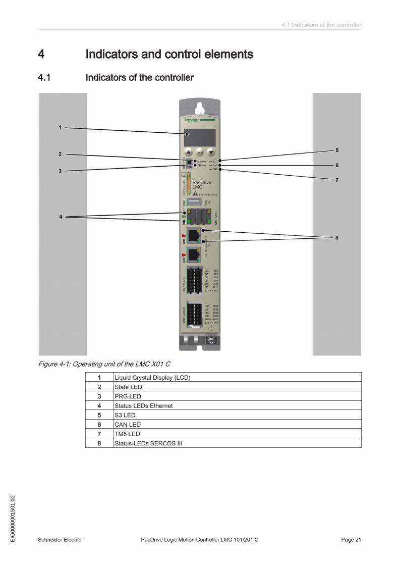
Figure 4-1: Operating unit of the LMC X01 C
1 Liquid Crystal Display (LCD)2 State LED3 PRG LED4 Status LEDs Ethernet5 S3 LED6 CAN LED7 TM5 LED8 Status-LEDs SERCOS III
4.1 Indicators of the controller
Schneider Electric PacDrive Logic Motion Controller LMC 101/201 C Page 21EIO
0000
0015
01.0
0
4.1.1 Liquid Crystal Display (LCD)
Liquid Crystal Display (LCD)
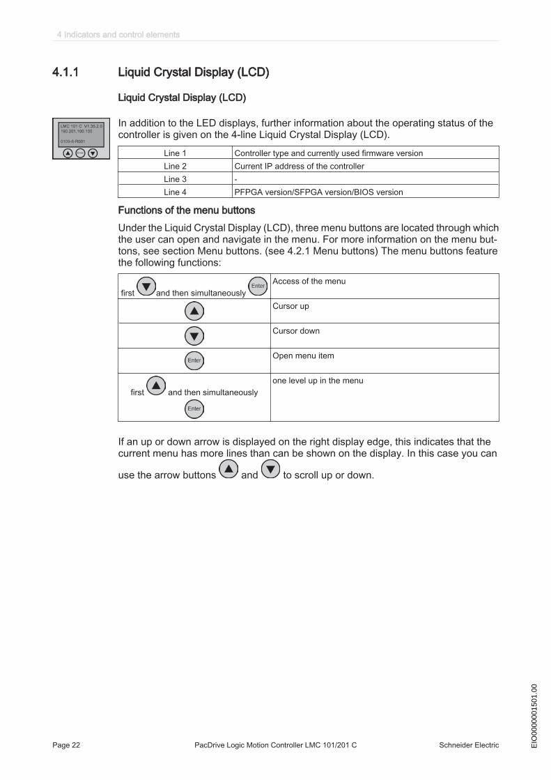
In addition to the LED displays, further information about the operating status of thecontroller is given on the 4-line Liquid Crystal Display (LCD).
Line 1 Controller type and currently used firmware versionLine 2 Current IP address of the controllerLine 3 -Line 4 PFPGA version/SFPGA version/BIOS version
Functions of the menu buttonsUnder the Liquid Crystal Display (LCD), three menu buttons are located through whichthe user can open and navigate in the menu. For more information on the menu but‐tons, see section Menu buttons. (see 4.2.1 Menu buttons) The menu buttons featurethe following functions:
first and then simultaneously Access of the menu
Cursor up
Cursor down
Open menu item
first and then simultaneouslyone level up in the menu
If an up or down arrow is displayed on the right display edge, this indicates that thecurrent menu has more lines than can be shown on the display. In this case you can
use the arrow buttons and to scroll up or down.
4 Indicators and control elements
Page 22 PacDrive Logic Motion Controller LMC 101/201 C Schneider Electric EIO
0000
0015
01.0
0

Menu navigation
Figure 4-2: Menu navigation
Description of the menu navigationThe submenu "Versions" provides an overview of all the software and hardware ver‐sions installed on the controller.
FW Currently used firmware versionPFPGA Version of the PacDrive-FPGA softwareSFPGA Version of the System-FPGA softwareBIOS BIOS version
In the submenu "HCode/SerialNo." a serial number and the hardware code are dis‐played. The serial number is a unique number which is used to identify the controller.The hardware code indicates the revision status.
Serial number Controller serial numberHardware code: Controller hardware code
4.1 Indicators of the controller
Schneider Electric PacDrive Logic Motion Controller LMC 101/201 C Page 23EIO
0000
0015
01.0
0

In the submenu "IP address" the IP address, the subnet mask and the gateway aredisplayed.
IP IP address of the controllerMASK Subnet maskGW Gateway
The MAC address is specified in the submenu "MAC address". The MAC address isa clear address of the device to identify the device in the network.
MAC address MAC address
In the submenu "Inputs" the user can prompt the logic state of each input. The digitalinputs correspond to standard IEC61131-2 type 1. Touchprobes and fast inputs havea resolution of 10 µs. Fast inputs can be used to trigger an interrupt.
DI Digital InputADI Advanced Digital Input
In the submenu "Outputs" the user can prompt the logic state of each output.
DQ Outputs
In the submenu "DiagMessage" the diagnostic class, the diagnostic code and the di‐agnostic text are displayed. The system assigns each diagnostic message a specificdiagnostic class when enabled. The diagnostic code is a code that encrypts a certaindiagnostic. In the diagnostic text a diagnostic is described in detail.
A:BBBB:C...C
A: Diagnostic classBBBB: Diagnostic codeC...C: Diagnostic text
In the submenu "Select language" the user can choose the display language.
Select languageGermanEnglish
Display language is GermanDisplay language is English
4 Indicators and control elements
Page 24 PacDrive Logic Motion Controller LMC 101/201 C Schneider Electric EIO
0000
0015
01.0
0

4.1.2 State LED
The State LED indicates whether a control voltage is applied, whether errors are de‐tected by the controller and whether the controller performs a minimum boot.
OFF The control voltage (24 Vdc) is missing or too low.GREEN Normal operation, control voltage in normal rangeRED system error detected, error is shown on the display
Initialization active after power onan error is detected by the controller after initialization, for further infor‐mation on the error, see the message logger
Quickly flashes RED The controller performs a minimal boot
4.1.3 PRG LED
The PRG LED indicates the state of the USB communication on Prog Port (CN1).
OFF no USB communication on Prog PortGREEN USB communication detected
The function to establish a connection to the controller via USB is currently not avail‐able.
4.1.4 S3 LED
The S3 LED indicates the state and the phases of the SERCOS III communication.
LED Color
LED Status
Meaning Instructions/informa‐tion for the user
Notes
OFF No SERCOS III communication - -
ORANGE The device is in a communicationphase CP0 up to and includingCP3.
- SERC3.State = 0..3
GREEN SERCOS III communication incommunication phase CP4 withouterror
- SERC3.State = 4
RED Detected communication error Reset condition:■ DiagQuit
SERC3.State = 11
4.1 Indicators of the controller
Schneider Electric PacDrive Logic Motion Controller LMC 101/201 C Page 25EIO
0000
0015
01.0
0

4.1.5 CAN LED
CAN-LED is a two-color light-emitting diode (LED), alternating between two states: aRun state (green color) and an Error state (red color). CAN-LED colors can be flickering(every 50ms), or blinking (every 200ms), or flashing (1, 2 or 3 flashes), or steady, asdescribed below.
State Color display mode MeaningOff - no powerFlickering green the LED repeatedly flickers on for
50ms, then off for 50msautobaud detection in progress
Blinking green the LED repeatedly flickers on for200ms, then off for 200ms
pre-operational state
Flashing green single flash: The LED flashes on for200ms, then off for 1000ms
stopped state
Green steady operating stateFlashing red single flash: The LED flashes on for
200ms, then off for 1000mslimit to trigger diagnostic messagereached
double flash: The LED flashes on for200ms, off for 200ms, on for 200ms,then off for 1000ms
a cyclic checking has detected an er‐ror
triple flash: The LED flashes on for200ms, off for 200ms, on for 200ms,off for 200ms, on for 200ms, then offfor 1000ms
Synchronisation error detected. noSync message received within theconfigured communication cycle time‐out
red steady bus off
4.1.6 TM5 LED
The TM5 LED indicates the state of the TM5 communication.
OFF no TM5 communicationGREEN TM5 communication available (the bus is activated and works properly)RED Communication error detected
TM5 is in preparation.
4 Indicators and control elements
Page 26 PacDrive Logic Motion Controller LMC 101/201 C Schneider Electric EIO
0000
0015
01.0
0
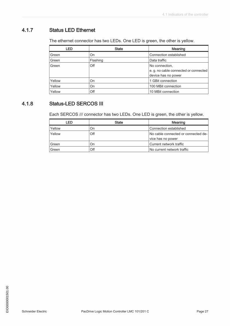
4.1.7 Status LED Ethernet
The ethernet connector has two LEDs. One LED is green, the other is yellow.
LED State MeaningGreen On Connection establishedGreen Flashing Data trafficGreen Off No connection,
e. g. no cable connected or connecteddevice has no power
Yellow On 1 GBit connectionYellow On 100 MBit connectionYellow Off 10 MBit connection
4.1.8 Status-LED SERCOS III
Each SERCOS /// connector has two LEDs. One LED is green, the other is yellow.
LED State MeaningYellow On Connection establishedYellow Off No cable connected or connected de‐
vice has no powerGreen On Current network trafficGreen Off No current network traffic
4.1 Indicators of the controller
Schneider Electric PacDrive Logic Motion Controller LMC 101/201 C Page 27EIO
0000
0015
01.0
0

4.2 Operating elements of the controller
4.2.1 Menu buttons
Three menu buttons are located on the front side of the controller. With these menubuttons, the user can open and navigate through the menu.
Figure 4-3: Overview of menu buttons
1 Up arrow button2 Enter button3 Down arrow button
4.2.2 SD card-slot
The SD card slot is located on the front side of the controller.
The SD card slot is the receptacle for the permanent data storage (SD card) of thecontroller.
General information on the SD card
NOTICEPOSSIBLE DATA LOSS BECAUSE OF SWITCHING OFF THE CONTROLLER.
• Do not shutdown the controller while something is written on the SD card.Failure to follow these instructions can result in equipment damage.
NOTICEPOSSIBLE DATA LOSS BY POWER SUPPLY FAILURE
• Use external UPS to bridge power supply failures.Failure to follow these instructions can result in equipment damage.
4 Indicators and control elements
Page 28 PacDrive Logic Motion Controller LMC 101/201 C Schneider Electric EIO
0000
0015
01.0
0
The controller saves data up to 25ms after the loss of the power supply. To avoid dataloss an external UPS should be used.
Function of theSD card
The operating system, the Schneider Electric firmware and an EPAS project is storedon the SD card. After the system run-up, the software is loaded on the controller. It isalso possible to store license points for libraries on the SD card.Only use SD cards approved by Schneider Electric for this device.
There is no display that shows that the SD card has been accessed.
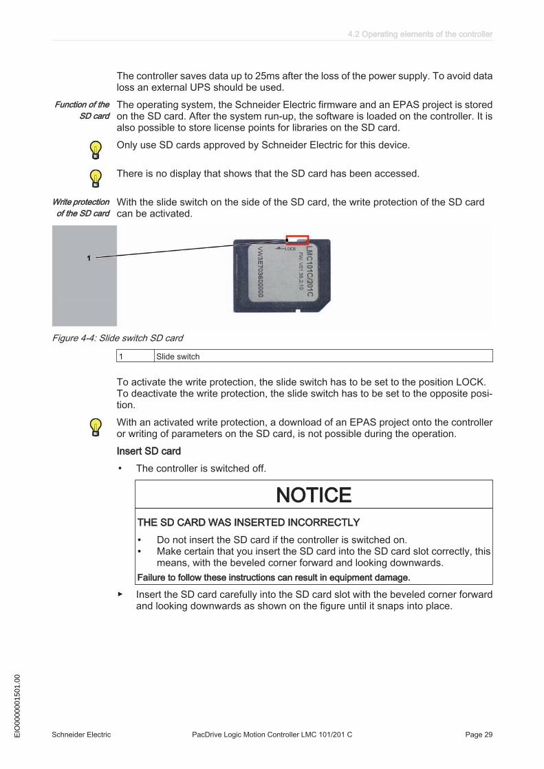
Write protectionof the SD card
With the slide switch on the side of the SD card, the write protection of the SD cardcan be activated.
Figure 4-4: Slide switch SD card
1 Slide switch
To activate the write protection, the slide switch has to be set to the position LOCK. To deactivate the write protection, the slide switch has to be set to the opposite posi‐tion.With an activated write protection, a download of an EPAS project onto the controlleror writing of parameters on the SD card, is not possible during the operation.Insert SD card
▪ The controller is switched off.
NOTICETHE SD CARD WAS INSERTED INCORRECTLY
• Do not insert the SD card if the controller is switched on.• Make certain that you insert the SD card into the SD card slot correctly, this
means, with the beveled corner forward and looking downwards.Failure to follow these instructions can result in equipment damage.
▶ Insert the SD card carefully into the SD card slot with the beveled corner forwardand looking downwards as shown on the figure until it snaps into place.
4.2 Operating elements of the controller
Schneider Electric PacDrive Logic Motion Controller LMC 101/201 C Page 29EIO
0000
0015
01.0
0
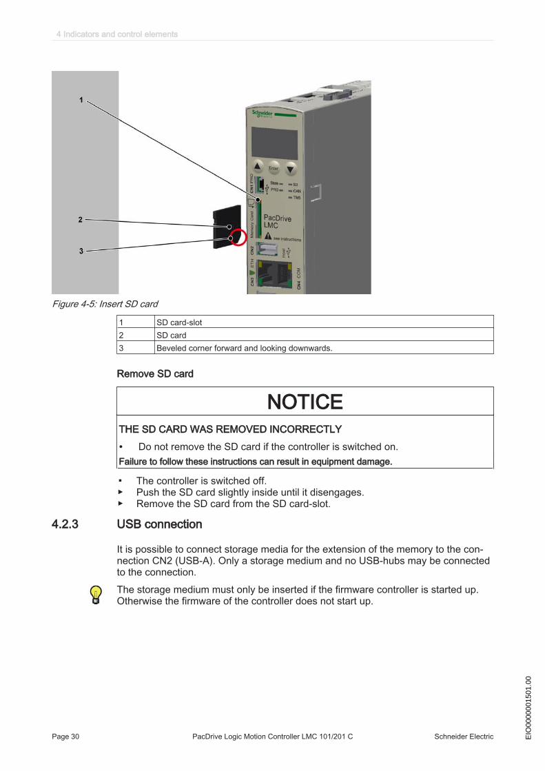
Figure 4-5: Insert SD card
1 SD card-slot2 SD card3 Beveled corner forward and looking downwards.
Remove SD card
NOTICETHE SD CARD WAS REMOVED INCORRECTLY
• Do not remove the SD card if the controller is switched on.Failure to follow these instructions can result in equipment damage.
▪ The controller is switched off.▶ Push the SD card slightly inside until it disengages.▶ Remove the SD card from the SD card-slot.
4.2.3 USB connection
It is possible to connect storage media for the extension of the memory to the con‐nection CN2 (USB-A). Only a storage medium and no USB-hubs may be connectedto the connection.The storage medium must only be inserted if the firmware controller is started up.Otherwise the firmware of the controller does not start up.
4 Indicators and control elements
Page 30 PacDrive Logic Motion Controller LMC 101/201 C Schneider Electric EIO
0000
0015
01.0
0

5 Installation and maintenanceFor warranty reasons, we recommend that you employ Schneider Electric personnelfor initial start-up. The Schneider Electric personnel
• will check the equipment,• determine the optimal configuration• and instruct the operating staff.
▶ Proceed with care during the following steps and take all precautions describedin order to help to avoid the following points:
• Injuries and material damage• Incorrect installation and programming of components• the incorrect operation of components• The use of non-authorized cables or modified components
5.1 Commissioning
5.1.1 Preparing commissioning
ESD protection ▶ Observe the following instructions for ESD protection in order to avoid any damagedue to electrostatic discharge:
NOTICEELECTROSTATIC DISCHARGE
• Do not touch any of the electrical connections.• Prevent electrostatic charges; e.g., by wearing appropriate clothing.• Remove existing static charge by touching a grounded, metallic surface, like
for example, a grounded housing.Failure to follow these instructions can result in equipment damage.
Unpacking How to unpack the device:▶ Remove packaging.▶ Dispose of the packaging material in accordance with the relevant local regula‐
tions.Verifying How to check the device:
▶ Verify that the delivery is complete.▶ Verify if the device is in working condition.
WARNINGDAMAGED OR MODIFIED DRIVE SYSTEMS
• Do not mount or commission damaged drive systems.• Do not modify the drive systems.• Send back inoperative devices.Failure to follow these instructions can result in death or serious injury.
▶ Check data against type plates.
▶ Observe requirements for the installation location.▶ Observe requirements for the degree of protection and the EMC rules.▶ Then install LMC.
5.1 Commissioning
Schneider Electric PacDrive Logic Motion Controller LMC 101/201 C Page 31EIO
0000
0015
01.0
0

5.1.2 Wiring of the controller▶ Connect the controller, beginning with the shielded connector.▶ Check the continuity of the protective conductor system.▶ Check if the shielding is completely correct.▶ Check whether the memory card has been inserted.▶ Eliminate the possibility of short circuits and interruptions.▶ Check if the terminals are fastened securely and the necessary cable cross sec‐
tions are correct.
NOTICEINCORRECT POLARITY, INCORRECT POWER SUPPLY
• When connecting the CN9 connection do not interchange the positive pole withthe negative pole.
• Supply the controller with 24V DC.Failure to follow these instructions can result in equipment damage.▶ Connect the CN9 connection of the controller to an external mains adapter.▶ Establish a SERCOS III connection via the CN5 and CN6 connections.
WARNINGUNINTENDED EQUIPMENT OPERATION
• Connect the control voltage to the inputs and outputs properly.Failure to follow these instructions can result in death or serious injury.▶ Connect all further connections according to their local device configuration.
NOTICEOVERHEATING BECAUSE OF HIGH AMBIENT TEMPERATURES
• For ambient temperatures >55°C (131°F), ensure that there is additional re-circulation of the cooling air in the control cabinet (external fan).
Failure to follow these instructions can result in equipment damage.
For further information on this (see 6.1 Ambient conditions).
▶ Switch on the supply voltage of the controller.The LMC is initialized and the LEDs show the following condition: LED status during initialization: State-LED: red LED status after initialization: State-LED: green
Configure the output CN8 as Watchdog.
WARNINGFAILURE TO MEET SAFETY FUNCTION REQUIREMENTS
• Do not use the Watchdog output to realize IEC 61508:2010 and EN ISO13849:2008 safety function.
Failure to follow these instructions can result in death or serious injury.
5 Installation and maintenance
Page 32 PacDrive Logic Motion Controller LMC 101/201 C Schneider Electric EIO
0000
0015
01.0
0

NOTICEINCORRECT POLARITY OF THE POWER SUPPLY OF THE OUTPUTS
• When connecting the CN8 connection do not interchange the positive poles (pin5 and pin 11) with the negative poles (pin 6 and pin 12).
Failure to follow these instructions can result in equipment damage.
On the connection CN8 it is possible to configure the output DQ7 as Watchdog. Atdelivery, it is not configured as watchdog but as standard output.For further information on this, see the online help of SoMachine Motion.
Grounding screw connectionTighten the grounding screw with a 1.4 Nm (12.4 ibf in) torque.External UPS
NOTICEPOSSIBLE DATA LOSS BY POWER SUPPLY FAILURE
• Use external UPS to bridge power supply failures.Failure to follow these instructions can result in equipment damage.
The controller saves data up to 25ms after the loss of the power supply. To avoid dataloss an external UPS should be used.
5.1.3 Preparing the control cabinet
WARNINGFLAMMABLE MATERIALS
• Do not install flammable materials in the immediate vicinity.Failure to follow these instructions can result in death or serious injury.▶ Avoid "Hot Spot" in the control cabinet.
DANGERELECTRIC SHOCK DUE TO MISSING GROUNDING
• At the installation points, remove paint across a large surface, before installingthe devices (metallically blank).
Failure to follow these instructions will result in death or serious injury.▶ If necessary, install additional fan.▶ Keep a distance of at least 100mm ( 3.94in.) above and below the devices.▶ Mount the controller vertically inside the control cabinet.
5.1 Commissioning
Schneider Electric PacDrive Logic Motion Controller LMC 101/201 C Page 33EIO
0000
0015
01.0
0
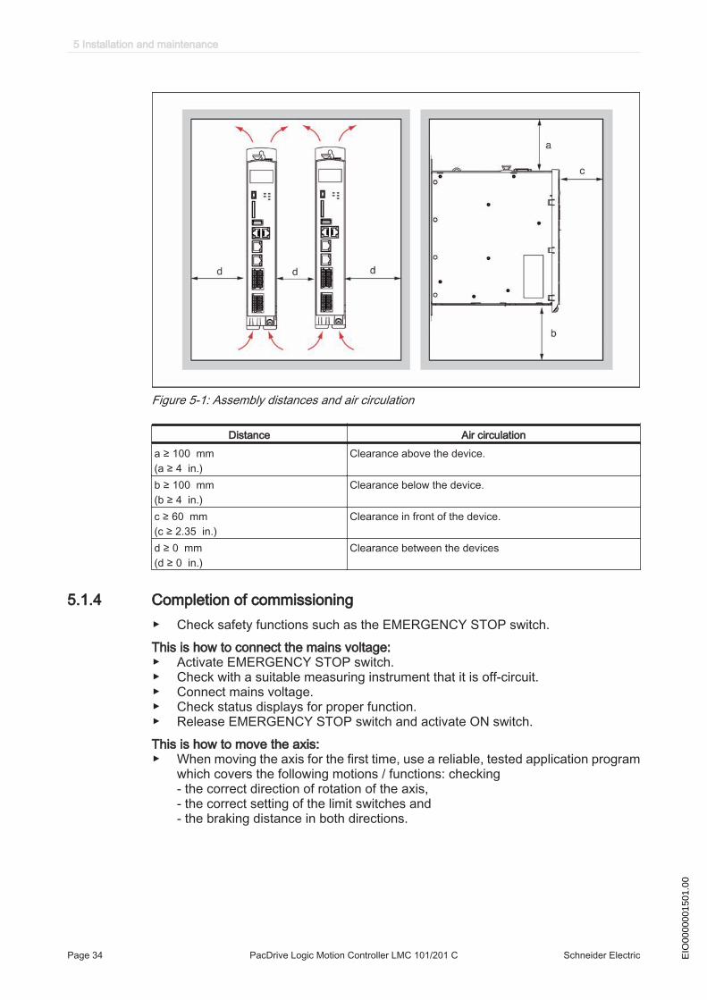
Figure 5-1: Assembly distances and air circulation
Distance Air circulationa ≥ 100 mm(a ≥ 4 in.)
Clearance above the device.
b ≥ 100 mm(b ≥ 4 in.)
Clearance below the device.
c ≥ 60 mm(c ≥ 2.35 in.)
Clearance in front of the device.
d ≥ 0 mm(d ≥ 0 in.)
Clearance between the devices
5.1.4 Completion of commissioning▶ Check safety functions such as the EMERGENCY STOP switch.This is how to connect the mains voltage:▶ Activate EMERGENCY STOP switch.▶ Check with a suitable measuring instrument that it is off-circuit.▶ Connect mains voltage.▶ Check status displays for proper function.▶ Release EMERGENCY STOP switch and activate ON switch.This is how to move the axis:▶ When moving the axis for the first time, use a reliable, tested application program
which covers the following motions / functions: checking - the correct direction of rotation of the axis,- the correct setting of the limit switches and- the braking distance in both directions.
5 Installation and maintenance
Page 34 PacDrive Logic Motion Controller LMC 101/201 C Schneider Electric EIO
0000
0015
01.0
0

This is how to transmit the configuration and the program:▶ Transfer the project with the Automation Toolkit SoMachine Motion EPAS to the
PacDrive controller.
WARNINGHAZARDOUS MOVEMENTS
• Ensure that no persons are in the danger zone.• Remove all tools, loose parts and other working aids not belonging to the
axis/machine/system from the area of movement.• Engaged the engine only after the function test has been successfully per‐
formed.Failure to follow these instructions can result in death or serious injury.
Adjust real-time clockThe real-time clock is not adjusted at the time of delivery of the device. Summer andwinter time is not considered by the device. If the real-time clock is not adjusted, thetime and date specifications in the message logger will not be correct. Make certainthat the real-time clock is adjusted correctly.
5.1.5 Performing the function test▶ Verify devices and wiring again.▶ If you haven't already done so, connect the mains voltage.▶ Carry out function test using a checklist for axis/machine/system functions.▶ Resume system operation according to the operating manual (from the machine
manufacturer and servo amplifier).
5.2 Configuration, homing and programming
Use the Automation Toolkit SoMachine Motion EPAS to adapt the PacDrive systemto its task. In SoMachine Motion EPAS the system is configured and programmedaccording to IEC 61131-3.
NOTICEIMPROPER PROGRAM CHANGES
• Program changes may only be carried out by trained personnel with detailedknowledge of the system.
• Changes may only be carried out by your machine supplier or by Schneider em‐ployees.
• Schneider is not liable for damages caused by unauthorized program changes.Failure to follow these instructions can result in equipment damage.
5.2 Configuration, homing and programming
Schneider Electric PacDrive Logic Motion Controller LMC 101/201 C Page 35EIO
0000
0015
01.0
0

5.3 Diagnostics
5.3.1 Connection to controller
Connecting the (Service) PC (SoMachine Motion EPAS) to the controller:▶ Start SoMachine Motion EPAS.▶ Use File > New Project (1) to create a new project.
1
▶ Assign a project name (1).▶ Select Default project (2).▶ Select PacDrive LMC x01 (Schneider Electric) (3).▶ Select the firmware of the controller (4).▶ Select Structured text (5) as the language for SR_MAIN.▶ Select project file location (6).▶ Confirm with OK afterwards..
▶ Double click on the Device (PacDrive LMC x01C) (1) in the device window at theleft screen edge.
5 Installation and maintenance
Page 36 PacDrive Logic Motion Controller LMC 101/201 C Schneider Electric EIO
0000
0015
01.0
0
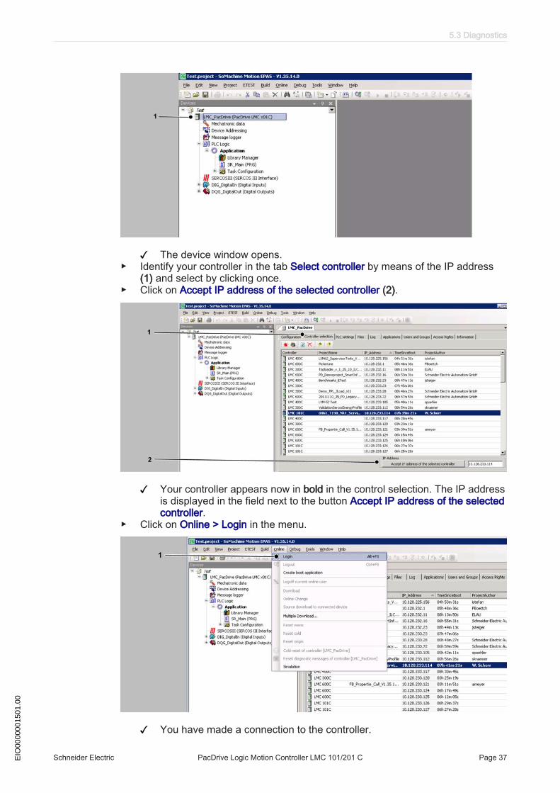
The device window opens.▶ Identify your controller in the tab Select controller by means of the IP address
(1) and select by clicking once.▶ Click on Accept IP address of the selected controller (2).
Your controller appears now in bold in the control selection. The IP addressis displayed in the field next to the button Accept IP address of the selectedcontroller.
▶ Click on Online > Login in the menu.
You have made a connection to the controller.
5.3 Diagnostics
Schneider Electric PacDrive Logic Motion Controller LMC 101/201 C Page 37EIO
0000
0015
01.0
0
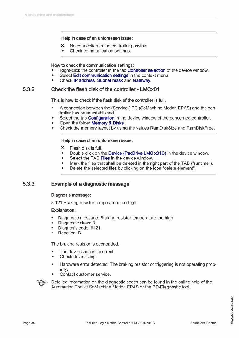
Help in case of an unforeseen issue:No connection to the controller possible
▶ Check communication settings.
How to check the communication settings:▶ Right-click the controller in the tab Controller selection of the device window.▶ Select Edit communication settings in the context menu.▶ Check IP address, Subnet mask and Gateway.
5.3.2 Check the flash disk of the controller - LMCx01
This is how to check if the flash disk of the controller is full.
▪ A connection between the (Service-) PC (SoMachine Motion EPAS) and the con‐troller has been established.
▶ Select the tab Configuration in the device window of the concerned controller.▶ Open the folder Memory & Disks.▶ Check the memory layout by using the values RamDiskSize and RamDiskFree.
Help in case of an unforeseen issue:Flash disk is full.
▶ Double click on the Device (PacDrive LMC x01C) in the device window.▶ Select the TAB Files in the device window.▶ Mark the files that shall be deleted in the right part of the TAB ("runtime").▶ Delete the selected files by clicking on the icon "delete element".
5.3.3 Example of a diagnostic message
Diagnosis message:8 121 Braking resistor temperature too highExplanation:
• Diagnostic message: Braking resistor temperature too high• Diagnostic class: 3• Diagnosis code: 8121• Reaction: B
The braking resistor is overloaded.
▪ The drive sizing is incorrect.▶ Check drive sizing.
▪ Hardware error detected: The braking resistor or triggering is not operating prop‐erly.
▶ Contact customer service.Detailed information on the diagnostic codes can be found in the online help of theAutomation Toolkit SoMachine Motion EPAS or the PD-Diagnostic tool.
5 Installation and maintenance
Page 38 PacDrive Logic Motion Controller LMC 101/201 C Schneider Electric EIO
0000
0015
01.0
0
5.4 Electromagnetic Compatibility, EMC
WARNINGRISK OF ELECTROMAGNETIC DISTURBANCES OF SIGNALS AND DEVICES
• Use proper EMC shielding techniques to help prevent unexpected device oper‐ation.
Failure to follow these instructions can result in death or serious injury.
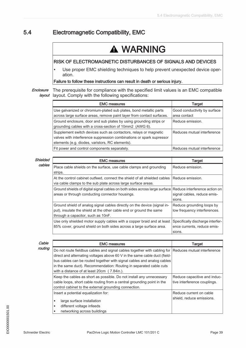
Enclosure layout
The prerequisite for compliance with the specified limit values is an EMC compatiblelayout. Comply with the following specifications:
EMC measures TargetUse galvanized or chromium-plated sub plates, bond metallic partsacross large surface areas, remove paint layer from contact surfaces.
Good conductivity by surfacearea contact
Ground enclosure, door and sub plates by using grounding strips orgrounding cables with a cross-section of 10mm2 (AWG 6).
Reduce emission.
Supplement switch devices such as contactors, relays or magneticvalves with interference suppression combinations or spark supressorelements (e.g. diodes, varistors, RC elements).
Reduces mutual interference
Fit power and control components separately. Reduces mutual interference
Shieldedcables
EMC measures TargetPlace cable shields on the surface, use cable clamps and groundingstrips.
Reduce emission.
At the control cabinet outfeed, connect the shield of all shielded cablesvia cable clamps to the sub plate across large surface areas.
Reduce emission.
Ground shields of digital signal cables on both sides across large surfaceareas or through conducting connector housings.
Reduce interference action onsignal cables, reduce emis‐sions.
Ground shield of analog signal cables directly on the device (signal in‐put), insulate the shield at the other cable end or ground the samethrough a capacitor, such as 10nF.
Reduce grounding loops bylow frequency interferences.
Use only shielded motor supply cables with a copper braid and at least85% cover, ground shield on both sides across a large surface area.
Specifically discharge interfer‐ence currents, reduce emis‐sions.
Cable routing
EMC measures TargetDo not route fieldbus cables and signal cables together with cabling fordirect and alternating voltages above 60 V in the same cable duct (field‐bus cables can be routed together with signal cables and analog cablesin the same duct). Recommendation: Routing in separated cable cutswith a distance of at least 20cm ( 7.84in.).
Reduces mutual interference
Keep the cables as short as possible. Do not install any unnecessarycable loops, short cable routing from a central grounding point in thecontrol cabinet to the external grounding connection.
Reduce capacitive and induc‐tive interference couplings.
Insert a potential equalization for:
• large surface installation• different voltage infeeds• networking across buildings
Reduce current on cableshield, reduce emissions.
5.4 Electromagnetic Compatibility, EMC
Schneider Electric PacDrive Logic Motion Controller LMC 101/201 C Page 39EIO
0000
0015
01.0
0
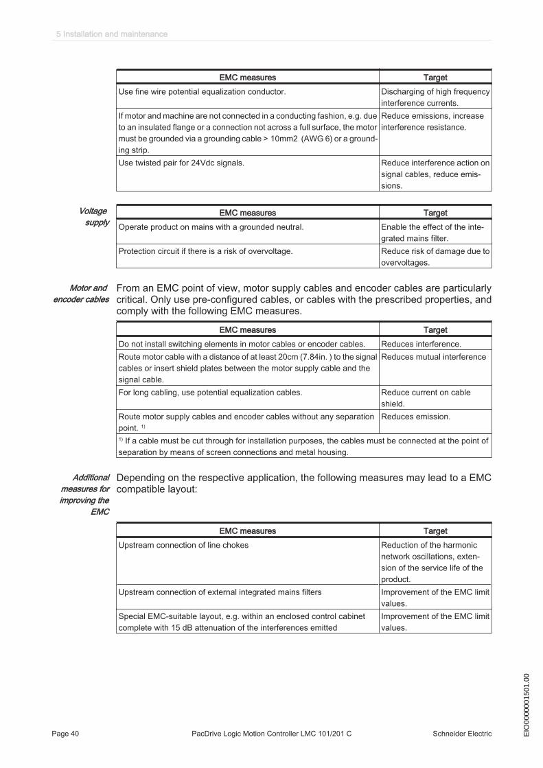
EMC measures TargetUse fine wire potential equalization conductor. Discharging of high frequency
interference currents.If motor and machine are not connected in a conducting fashion, e.g. dueto an insulated flange or a connection not across a full surface, the motormust be grounded via a grounding cable > 10mm2 (AWG 6) or a ground‐ing strip.
Reduce emissions, increaseinterference resistance.
Use twisted pair for 24Vdc signals. Reduce interference action onsignal cables, reduce emis‐sions.
Voltage supply
EMC measures TargetOperate product on mains with a grounded neutral. Enable the effect of the inte‐
grated mains filter.Protection circuit if there is a risk of overvoltage. Reduce risk of damage due to
overvoltages.
Motor and encoder cables
From an EMC point of view, motor supply cables and encoder cables are particularlycritical. Only use pre-configured cables, or cables with the prescribed properties, andcomply with the following EMC measures.
EMC measures TargetDo not install switching elements in motor cables or encoder cables. Reduces interference.Route motor cable with a distance of at least 20cm (7.84in. ) to the signalcables or insert shield plates between the motor supply cable and thesignal cable.
Reduces mutual interference
For long cabling, use potential equalization cables. Reduce current on cableshield.
Route motor supply cables and encoder cables without any separationpoint. 1)
Reduces emission.
1) If a cable must be cut through for installation purposes, the cables must be connected at the point ofseparation by means of screen connections and metal housing.
Additionalmeasures forimproving the
EMC
Depending on the respective application, the following measures may lead to a EMCcompatible layout:
EMC measures TargetUpstream connection of line chokes Reduction of the harmonic
network oscillations, exten‐sion of the service life of theproduct.
Upstream connection of external integrated mains filters Improvement of the EMC limitvalues.
Special EMC-suitable layout, e.g. within an enclosed control cabinetcomplete with 15 dB attenuation of the interferences emitted
Improvement of the EMC limitvalues.
5 Installation and maintenance
Page 40 PacDrive Logic Motion Controller LMC 101/201 C Schneider Electric EIO
0000
0015
01.0
0

5.5 Maintenance, repair, cleaning▶ Observe the following instructions before carrying out maintenance on Device:▶ De-energize Device.How to de-energize the system:▶ Set main switch to "OFF Position".▶ Prevent main switch from being switched back on.
5.5.1 Repair
In case of repair proceed as follows :▶ Contact the Schneider Electric Customer Service.
5.5.2 Cleaning
How to clean the controller:▶ De-energize controller.▶ Remove controller.
It is not possible to test in advance all materials of the Schneider Electric productrange that are used at the moment and in the future for compatibility with thecleaning agents available on the market.
NOTICEDAMAGE CAUSED BY CLEANING AGENTS
• Before using a cleaning agent, carry out a compatibility test in relation to thecleaning agent and the component affected.
• Do not use alkaline detergent as the polycarbonate can lose its stability ifyou come into contact with it.
• Do not use any chloride-containing cleaning agents as these corrode thestainless steel and in particular the welds, and thus reduce the strength ofthe mechanics.
Failure to follow these instructions can result in equipment damage.
For more information on the material properties of your component (see 6.3 Me‐chanical and electrical data).
▶ Then blow out controller with dry pressurized air (max. 1 bar (14.5 PSI)).
5.5.3 Battery, Real-time clock
The battery must be replaced every 10 years. After this time has elapsed, the batterymust be replaced. Only Schneider Electric personnel are authorized to replace thebattery. The contact addresses can be found in the chapter (see 8.1 Contact address‐es)If the battery is getting low then the message "Empty Battery" appears on the display.When the battery is empty and the 24 Vdc mains supply is disconnected then data(retain variables and all the data on the NVRAM) is not saved anymore.When the battery is empty the real-time clock is set to a default value by every startand the user has to set the real-time clock to the current value.
5.5 Maintenance, repair, cleaning
Schneider Electric PacDrive Logic Motion Controller LMC 101/201 C Page 41EIO
0000
0015
01.0
0
5.6 Spare part inventory▶ Keep a stock of the most important components to make certain the equipment is
functioning and ready for operation at all times.▶ Only exchange devices with the same hardware configuration.▶ Indicate the following information on the spare part order:Unicode: e.g. LMC101CHardware revision: e.g. RS:02
This information can be found on the logistic nameplate.
5.7 Device-, parts- or cable exchange
How to de-energize the system:▶ Set main switch to "OFF Position".▶ Prevent main switch from being switched back on.
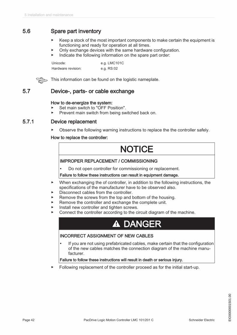
5.7.1 Device replacement▶ Observe the following warning instructions to replace the the controller safely.How to replace the controller:
NOTICEIMPROPER REPLACEMENT / COMMISSIONING
• Do not open controller for commissioning or replacement.Failure to follow these instructions can result in equipment damage.
▶ When exchanging the of controller, in addition to the following instructions, thespecifications of the manufacturer have to be observed also.
▶ Disconnect cables from the controller.▶ Remove the screws from the top and bottom of the housing.▶ Remove the controller and exchange the complete unit.▶ Install new controller and tighten screws.▶ Connect the controller according to the circuit diagram of the machine.
DANGERINCORRECT ASSIGNMENT OF NEW CABLES
• If you are not using prefabricated cables, make certain that the configurationof the new cables matches the connection diagram of the machine manu‐facturer.
Failure to follow these instructions will result in death or serious injury.
▶ Following replacement of the controller proceed as for the initial start-up.
5 Installation and maintenance
Page 42 PacDrive Logic Motion Controller LMC 101/201 C Schneider Electric EIO
0000
0015
01.0
0
Proceed as follows for start-up:▶ Import the user project with a PC, on which the Automation Toolkit SoMachine
Motion EPAS is installed.Or▶ Remove the already used flash disk from the controller that has to be repaired
and insert it into the new controller.▶ Ensure that the card is functional.▶ Store the PacDrive controller in a suitable transport packaging.▶ Put the system back in operation.
5.7 Device-, parts- or cable exchange
Schneider Electric PacDrive Logic Motion Controller LMC 101/201 C Page 43EIO
0000
0015
01.0
0
5.8 Fast Device Replacement
5.8.1 Introduction
With the help of the Fast Device Replacement, the Lexium 62, Lexium 52 and ILMdevices that are in the configuration of a SoMachine Motion project on the controllercan be exchanged. There are certain parameters that have to be set in SoMachineMotion first. Information on this can be found in the online help of SoMachine Motion.Subsequently, certain settings on the display of the controller have to be made whichare described in the following. The FDR display mechanism gives the possibility tomanually access the assignment between logical devices in the PLC configuration(SoMachine EPAS) and the physical connected devices.
5.8.2 Use
Error detected during the manual device assignmentIf two or more devices of the same type (or a Double Drive) are exchanged, it is pos‐sible that an incorrect manual assignment of the logical devices to the physical con‐nected devices is made.
WARNINGUNINTENDED OPERATING STATE OF THE DEVICE
• Make certain that the assignment of the logical devices to the physically con‐nected devices equates exactly the device assignment before the device ex‐change.
• Before commissioning the system, verify that the programmed logic controls thecorrect physical drives.
Failure to follow these instructions can result in death or serious injury.
Different device typesThe FDR display mechanism does not consider the device type of physical devices.If the logical device type does not equate to the assigned physical device type, then adevice assignment with the FDR display mechanism is possible but will lead to an errorduring the SERCOS phase start-up (8501 SERCOS slave not found). If FDRStart-Mode is set to the value Phase start-up/2, then the FDR display mechanism isrestarted.Further information on the parameters can be found under "Fast Device Replacement"in the online help of SoMachine Motion.
5 Installation and maintenance
Page 44 PacDrive Logic Motion Controller LMC 101/201 C Schneider Electric EIO
0000
0015
01.0
0
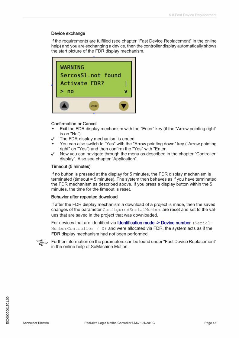
Device exchangeIf the requirements are fulfilled (see chapter "Fast Device Replacement" in the onlinehelp) and you are exchanging a device, then the controller display automatically showsthe start picture of the FDR display mechanism.
Confirmation or Cancel▶ Exit the FDR display mechanism with the "Enter" key (if the "Arrow pointing right"
is on "No").The FDR display mechanism is ended.
▶ You can also switch to "Yes" with the "Arrow pointing down" key ("Arrow pointingright" on "Yes") and then confirm the "Yes" with "Enter.Now you can navigate through the menu as described in the chapter "Controllerdisplay". Also see chapter "Application".
Timeout (5 minutes)If no button is pressed at the display for 5 minutes, the FDR display mechanism isterminated (timeout = 5 minutes). The system then behaves as if you have terminatedthe FDR mechanism as described above. If you press a display button within the 5minutes, the time for the timeout is reset.Behavior after repeated downloadIf after the FDR display mechanism a download of a project is made, then the savedchanges of the parameter ConfiguredSerialNumber are reset and set to the val‐ues that are saved in the project that was downloaded.For devices that are identified via Identification mode -> Device number (Serial-NumberController / 0) and were allocated via FDR, the system acts as if theFDR display mechanism had not been performed.Further information on the parameters can be found under "Fast Device Replacement"in the online help of SoMachine Motion.
5.8 Fast Device Replacement
Schneider Electric PacDrive Logic Motion Controller LMC 101/201 C Page 45EIO
0000
0015
01.0
0
5.8.3 Controller display
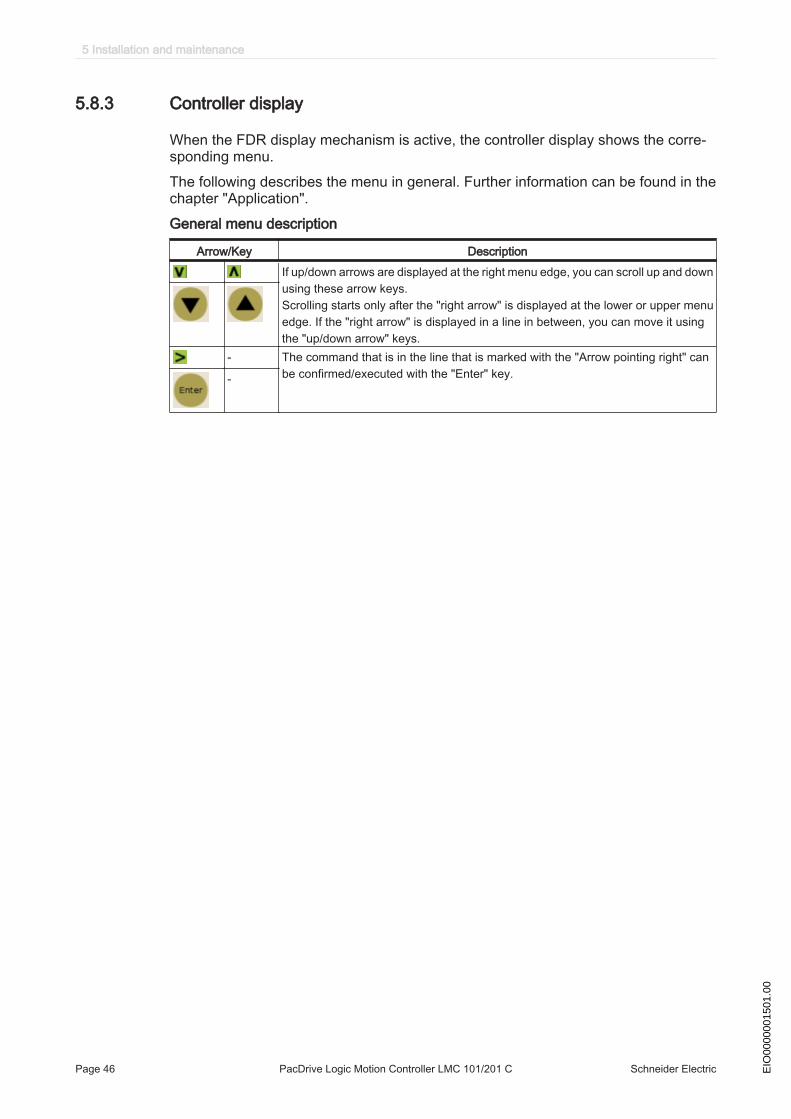
When the FDR display mechanism is active, the controller display shows the corre‐sponding menu.The following describes the menu in general. Further information can be found in thechapter "Application".General menu description
Arrow/Key DescriptionIf up/down arrows are displayed at the right menu edge, you can scroll up and downusing these arrow keys.Scrolling starts only after the "right arrow" is displayed at the lower or upper menuedge. If the "right arrow" is displayed in a line in between, you can move it usingthe "up/down arrow" keys.
- The command that is in the line that is marked with the "Arrow pointing right" canbe confirmed/executed with the "Enter" key.-
5 Installation and maintenance
Page 46 PacDrive Logic Motion Controller LMC 101/201 C Schneider Electric EIO
0000
0015
01.0
0
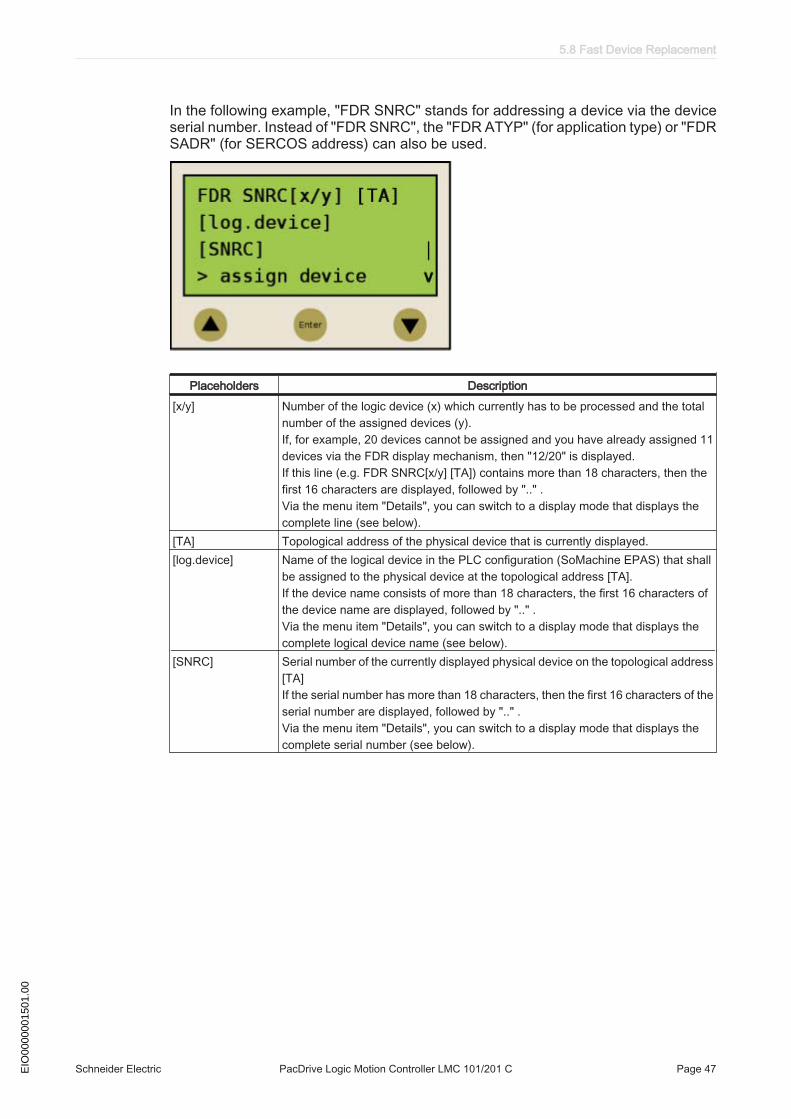
In the following example, "FDR SNRC" stands for addressing a device via the deviceserial number. Instead of "FDR SNRC", the "FDR ATYP" (for application type) or "FDRSADR" (for SERCOS address) can also be used.
Placeholders Description[x/y] Number of the logic device (x) which currently has to be processed and the total
number of the assigned devices (y).If, for example, 20 devices cannot be assigned and you have already assigned 11devices via the FDR display mechanism, then "12/20" is displayed. If this line (e.g. FDR SNRC[x/y] [TA]) contains more than 18 characters, then thefirst 16 characters are displayed, followed by ".." .Via the menu item "Details", you can switch to a display mode that displays thecomplete line (see below).
[TA] Topological address of the physical device that is currently displayed.[log.device] Name of the logical device in the PLC configuration (SoMachine EPAS) that shall
be assigned to the physical device at the topological address [TA].If the device name consists of more than 18 characters, the first 16 characters ofthe device name are displayed, followed by ".." .Via the menu item "Details", you can switch to a display mode that displays thecomplete logical device name (see below).
[SNRC] Serial number of the currently displayed physical device on the topological address[TA]If the serial number has more than 18 characters, then the first 16 characters of theserial number are displayed, followed by ".." .Via the menu item "Details", you can switch to a display mode that displays thecomplete serial number (see below).
5.8 Fast Device Replacement
Schneider Electric PacDrive Logic Motion Controller LMC 101/201 C Page 47EIO
0000
0015
01.0
0
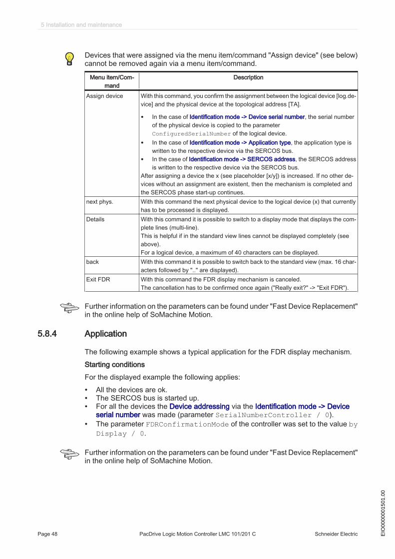
Devices that were assigned via the menu item/command "Assign device" (see below)cannot be removed again via a menu item/command.
Menu item/Com‐mand
Description
Assign device With this command, you confirm the assignment between the logical device [log.de‐vice] and the physical device at the topological address [TA].
• In the case of Identification mode -> Device serial number, the serial numberof the physical device is copied to the parameterConfiguredSerialNumber of the logical device.
• In the case of Identification mode -> Application type, the application type iswritten to the respective device via the SERCOS bus.
• In the case of Identification mode -> SERCOS address, the SERCOS addressis written to the respective device via the SERCOS bus.
After assigning a device the x (see placeholder [x/y]) is increased. If no other de‐vices without an assignment are existent, then the mechanism is completed andthe SERCOS phase start-up continues.
next phys. With this command the next physical device to the logical device (x) that currentlyhas to be processed is displayed.
Details With this command it is possible to switch to a display mode that displays the com‐plete lines (multi-line). This is helpful if in the standard view lines cannot be displayed completely (seeabove).For a logical device, a maximum of 40 characters can be displayed.
back With this command it is possible to switch back to the standard view (max. 16 char‐acters followed by ".." are displayed).
Exit FDR With this command the FDR display mechanism is canceled.The cancellation has to be confirmed once again ("Really exit?" -> "Exit FDR").
Further information on the parameters can be found under "Fast Device Replacement"in the online help of SoMachine Motion.
5.8.4 Application
The following example shows a typical application for the FDR display mechanism.Starting conditionsFor the displayed example the following applies:
• All the devices are ok.• The SERCOS bus is started up.• For all the devices the Device addressing via the Identification mode -> Device
serial number was made (parameter SerialNumberController / 0).• The parameter FDRConfirmationMode of the controller was set to the value by
Display / 0.
Further information on the parameters can be found under "Fast Device Replacement"in the online help of SoMachine Motion.
5 Installation and maintenance
Page 48 PacDrive Logic Motion Controller LMC 101/201 C Schneider Electric EIO
0000
0015
01.0
0

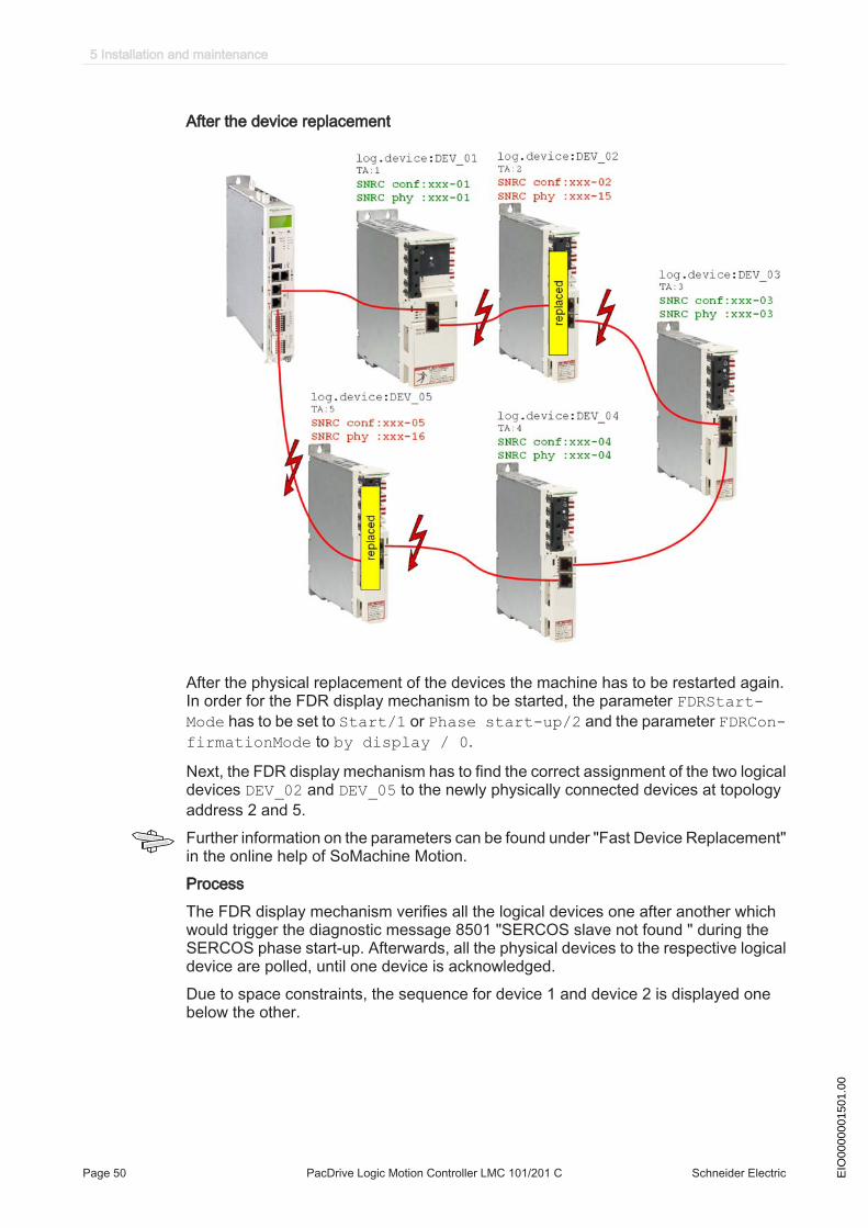
Device replacementThe following devices have to be replaced because of maintenance:
• The device at the topology address 2 (TA:2) with the logical device nameDEV_02 and the serial number SNRC phy: xxx-02 has to be replaced by thenew device that has the serial number SNRC phy: xxx-15.
• The device at the topology address 5 (TA:5) with the logical device nameDEV_05 and the serial number SNRC phy xxx-05 has to be replaced by the newdevice that has the serial number SNRC phy xxx-16.
5.8 Fast Device Replacement
Schneider Electric PacDrive Logic Motion Controller LMC 101/201 C Page 49EIO
0000
0015
01.0
0
After the device replacement
After the physical replacement of the devices the machine has to be restarted again.In order for the FDR display mechanism to be started, the parameter FDRStart-Mode has to be set to Start/1 or Phase start-up/2 and the parameter FDRCon-firmationMode to by display / 0.
Next, the FDR display mechanism has to find the correct assignment of the two logicaldevices DEV_02 and DEV_05 to the newly physically connected devices at topologyaddress 2 and 5.Further information on the parameters can be found under "Fast Device Replacement"in the online help of SoMachine Motion.ProcessThe FDR display mechanism verifies all the logical devices one after another whichwould trigger the diagnostic message 8501 "SERCOS slave not found " during theSERCOS phase start-up. Afterwards, all the physical devices to the respective logicaldevice are polled, until one device is acknowledged.Due to space constraints, the sequence for device 1 and device 2 is displayed onebelow the other.
5 Installation and maintenance
Page 50 PacDrive Logic Motion Controller LMC 101/201 C Schneider Electric EIO
0000
0015
01.0
0
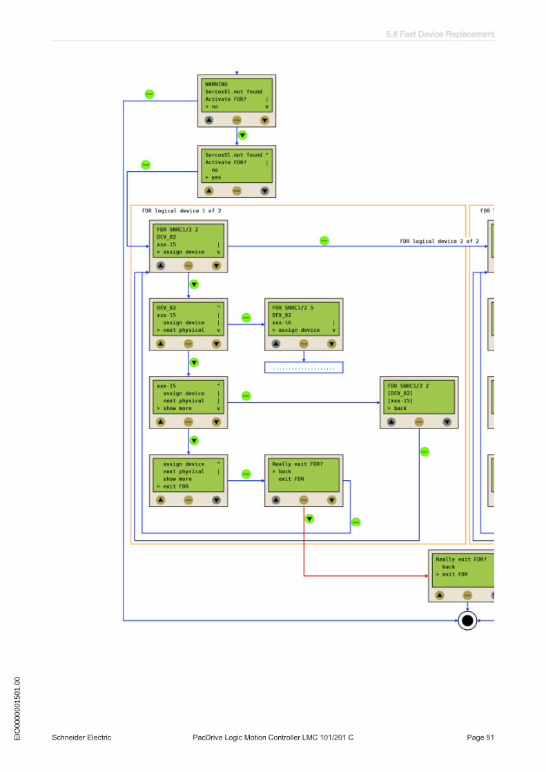
5.8 Fast Device Replacement
Schneider Electric PacDrive Logic Motion Controller LMC 101/201 C Page 51EIO
0000
0015
01.0
0

5 Installation and maintenance
Page 52 PacDrive Logic Motion Controller LMC 101/201 C Schneider Electric EIO
0000
0015
01.0
0
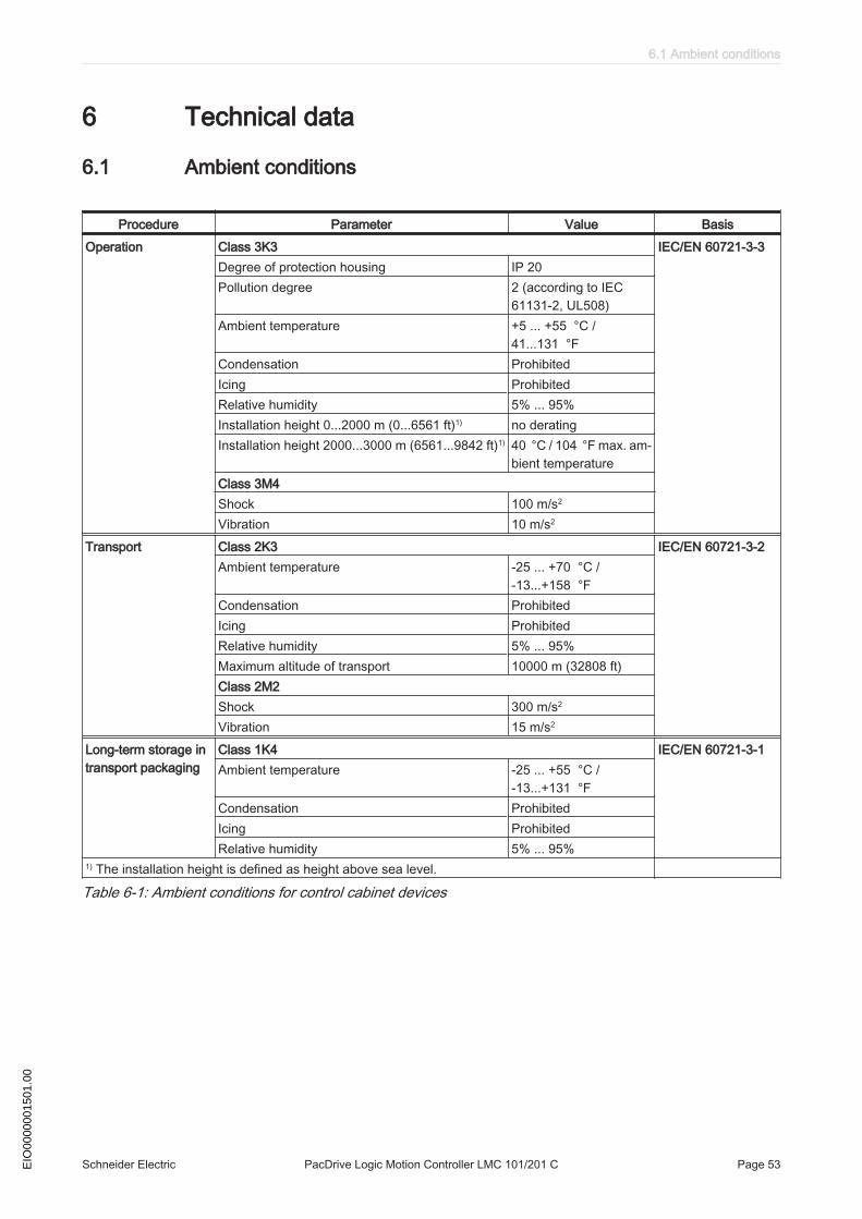
6 Technical data
6.1 Ambient conditions
Procedure Parameter Value BasisOperation Class 3K3 IEC/EN 60721-3-3
Degree of protection housing IP 20Pollution degree 2 (according to IEC
61131-2, UL508)Ambient temperature +5 ... +55 °C /
41...131 °FCondensation ProhibitedIcing ProhibitedRelative humidity 5% ... 95%Installation height 0...2000 m (0...6561 ft)1) no deratingInstallation height 2000...3000 m (6561...9842 ft)1) 40 °C / 104 °F max. am‐
bient temperatureClass 3M4Shock 100 m/s2
Vibration 10 m/s2
Transport Class 2K3 IEC/EN 60721-3-2Ambient temperature -25 ... +70 °C /
-13...+158 °FCondensation ProhibitedIcing ProhibitedRelative humidity 5% ... 95%Maximum altitude of transport 10000 m (32808 ft)Class 2M2Shock 300 m/s2
Vibration 15 m/s2
Long-term storage intransport packaging
Class 1K4 IEC/EN 60721-3-1Ambient temperature -25 ... +55 °C /
-13...+131 °FCondensation ProhibitedIcing ProhibitedRelative humidity 5% ... 95%
1) The installation height is defined as height above sea level.
Table 6-1: Ambient conditions for control cabinet devices
6.1 Ambient conditions
Schneider Electric PacDrive Logic Motion Controller LMC 101/201 C Page 53EIO
0000
0015
01.0
0
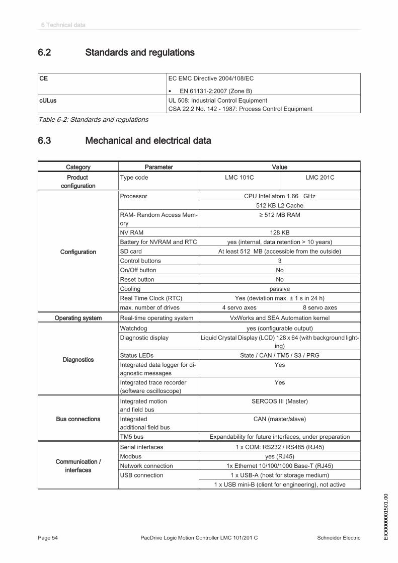
6.2 Standards and regulations
CE EC EMC Directive 2004/108/EC
• EN 61131-2:2007 (Zone B)cULus UL 508: Industrial Control Equipment
CSA 22.2 No. 142 - 1987: Process Control Equipment
Table 6-2: Standards and regulations
6.3 Mechanical and electrical data
Category Parameter ValueProduct
configurationType code LMC 101C LMC 201C
Configuration
Processor CPU Intel atom 1.66 GHz512 KB L2 Cache
RAM- Random Access Mem‐ory
≥ 512 MB RAM
NV RAM 128 KBBattery for NVRAM and RTC yes (internal, data retention > 10 years)SD card At least 512 MB (accessible from the outside)Control buttons 3On/Off button NoReset button NoCooling passiveReal Time Clock (RTC) Yes (deviation max. ± 1 s in 24 h)max. number of drives 4 servo axes 8 servo axes
Operating system Real-time operating system VxWorks and SEA Automation kernel
Diagnostics
Watchdog yes (configurable output)Diagnostic display Liquid Crystal Display (LCD) 128 x 64 (with background light‐
ing)Status LEDs State / CAN / TM5 / S3 / PRGIntegrated data logger for di‐agnostic messages
Yes
Integrated trace recorder(software oscilloscope)
Yes
Bus connections
Integrated motion and field bus
SERCOS III (Master)
Integratedadditional field bus
CAN (master/slave)
TM5 bus Expandability for future interfaces, under preparation
Communication /interfaces
Serial interfaces 1 x COM: RS232 / RS485 (RJ45)Modbus yes (RJ45)Network connection 1x Ethernet 10/100/1000 Base-T (RJ45)USB connection 1 x USB-A (host for storage medium)
1 x USB mini-B (client for engineering), not active
6 Technical data
Page 54 PacDrive Logic Motion Controller LMC 101/201 C Schneider Electric EIO
0000
0015
01.0
0

Category Parameter Value
Programming- languages IEC 61131-3 -
Continuous function chart (CFC)Function block diagram (FBD)
Instruction list (IL)Structured text (ST)Ladder diagram (LD)
Sequential function chart (SFC)
Touchprobe + Interruptinputs
Number 4 (TP & interrupt) (IEC61131-2 type1)Range UIN 0 Voltage -3 ... 5 VdcRange UIN 1 Voltage 15 ... 30 VdcInput current IIN = 4 mA at UIN = 24 VdcPolarized YesInput filter DI8...DI11 100µs - 4,29sTouchprobe resolution DI8 toDI11
10 µs at a SERCOS cycle time of 1, 2, 4 ms
digitalinputs
Number 8 (IEC61131-2 type1)Range UIN 0 Voltage -3 ... 5 VdcRange UIN 1 Voltage 15 ... 30 VdcInput current IIN = 4 mA at UIN = 24 VdcPolarized YesInput filter DI0...DI7 100µs - 4,29s
digitaloutputs
Number 8 (IEC61131-2 type1)Output voltage (+UL-3 V) < UOUT < +ULRated current Ie = 500 mA rated per output and 2A max for all outputs at
once (e.g. 8 outputs with 250 mA etc.)Inrush current Iemax < 2 A for 1 sLeakage current with 0 signal < = 0,5 mATransmission time < 100 µsshort circuit protection YesOpen circuit detection YesOpenload failure Rload > 150 kΩOverload failure UDQ+24V - UDQx > 4,0 V
Master encoder input Hiperface voltage output: 10 V / 200 mAanalog channel 0.9 V ... 1.1 Vpp / 2.2 ... 2.8V offset (max. 250
KHz)Parameter channel Hiperface RS485:
Cable length < = 50 m (164 ft)INC voltage output: 5 V / 300 mA
Level according to RS422 (max. 1 MHz)Cable length < = 50 m (164 ft)
Power supply
Power consumption of powersupply
20,4 Vdc - 30 Vdcmax. 30 W
Inrush current max. 10 ADimensions Dimensions of housing DxWxH (mm): 222 x 44 x 270
Weight Weight (with packaging) 2.2 kg (4.9 lbs)
Table 6-3: Technical data LMC 101/201 C
6.3 Mechanical and electrical data
Schneider Electric PacDrive Logic Motion Controller LMC 101/201 C Page 55EIO
0000
0015
01.0
0

6.4 Electrical connections
6.4.1 Connection overview controller
Figure 6-1: Connection overview front panel
Connec‐tion
Meaning Connection cross-section [mm2]/ [AWG] Tightening torque [Nm] / [lbfin]
CN1 Prog Port (USB mini-b), not active - -CN2 USB A - -CN3 Ethernet connection - -CN4 Serial link (COM) - -CN5 SERCOS III, port 1 - -CN6 SERCOS III, port 2 - -CN7 Digital inputs 0.2 … 1.5 / 24 ... 16 -CN8 Digital outputs 0.2 … 1.5 / 24 ... 16 -
6 Technical data
Page 56 PacDrive Logic Motion Controller LMC 101/201 C Schneider Electric EIO
0000
0015
01.0
0
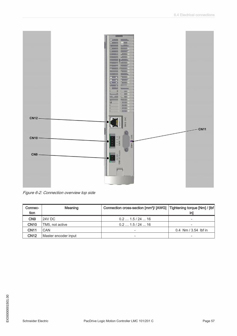
Figure 6-2: Connection overview top side
Connec‐tion
Meaning Connection cross-section [mm2]/ [AWG] Tightening torque [Nm] / [lbfin]
CN9 24V DC 0.2 … 1.5 / 24 ... 16 -CN10 TM5, not active 0.2 … 1.5 / 24 ... 16 -CN11 CAN - 0.4 Nm / 3.54 lbf inCN12 Master encoder input - -
6.4 Electrical connections
Schneider Electric PacDrive Logic Motion Controller LMC 101/201 C Page 57EIO
0000
0015
01.0
0

Figure 6-3: Connection overview bottom side
Connec‐tion
Meaning Connection cross-section [mm2]/ [AWG] Tightening torque [Nm] / [lbfin]
CN16 Option - -
6 Technical data
Page 58 PacDrive Logic Motion Controller LMC 101/201 C Schneider Electric EIO
0000
0015
01.0
0
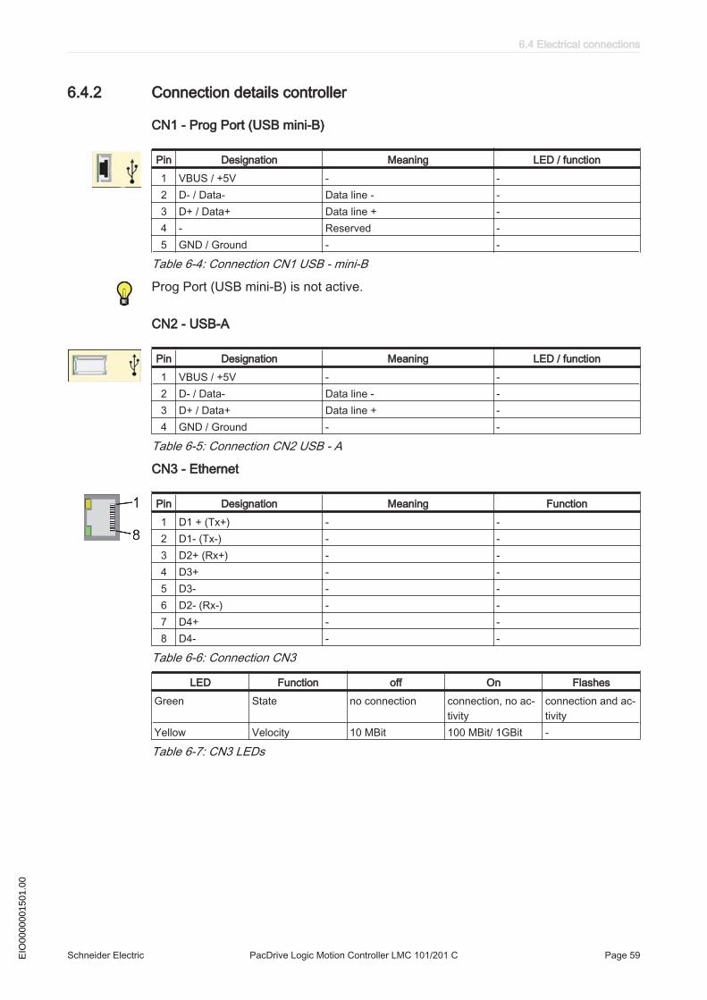
6.4.2 Connection details controller
CN1 - Prog Port (USB mini-B)
Pin Designation Meaning LED / function1 VBUS / +5V - -2 D- / Data- Data line - -3 D+ / Data+ Data line + -4 - Reserved -5 GND / Ground - -
Table 6-4: Connection CN1 USB - mini-B
Prog Port (USB mini-B) is not active.
CN2 - USB-A
Pin Designation Meaning LED / function1 VBUS / +5V - -2 D- / Data- Data line - -3 D+ / Data+ Data line + -4 GND / Ground - -
Table 6-5: Connection CN2 USB - A
CN3 - Ethernet
Pin Designation Meaning Function1 D1 + (Tx+) - -2 D1- (Tx-) - -3 D2+ (Rx+) - -4 D3+ - -5 D3- - -6 D2- (Rx-) - -7 D4+ - -8 D4- - -
Table 6-6: Connection CN3
LED Function off On FlashesGreen State no connection connection, no ac‐
tivityconnection and ac‐tivity
Yellow Velocity 10 MBit 100 MBit/ 1GBit -
Table 6-7: CN3 LEDs
6.4 Electrical connections
Schneider Electric PacDrive Logic Motion Controller LMC 101/201 C Page 59EIO
0000
0015
01.0
0
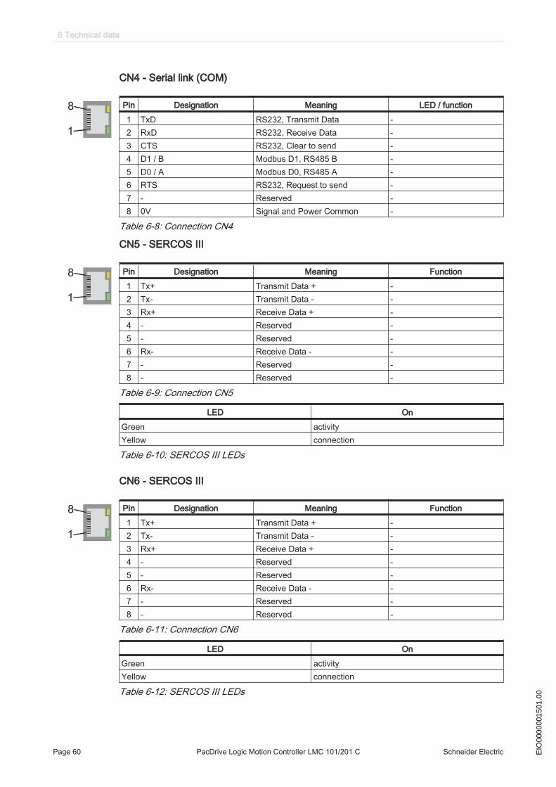
CN4 - Serial link (COM)
1
8 Pin Designation Meaning LED / function1 TxD RS232, Transmit Data -2 RxD RS232, Receive Data -3 CTS RS232, Clear to send -4 D1 / B Modbus D1, RS485 B -5 D0 / A Modbus D0, RS485 A -6 RTS RS232, Request to send -7 - Reserved -8 0V Signal and Power Common -
Table 6-8: Connection CN4
CN5 - SERCOS III
1
8 Pin Designation Meaning Function1 Tx+ Transmit Data + -2 Tx- Transmit Data - -3 Rx+ Receive Data + -4 - Reserved -5 - Reserved -6 Rx- Receive Data - -7 - Reserved -8 - Reserved -
Table 6-9: Connection CN5
LED OnGreen activityYellow connection
Table 6-10: SERCOS III LEDs
CN6 - SERCOS III
1
8 Pin Designation Meaning Function1 Tx+ Transmit Data + -2 Tx- Transmit Data - -3 Rx+ Receive Data + -4 - Reserved -5 - Reserved -6 Rx- Receive Data - -7 - Reserved -8 - Reserved -
Table 6-11: Connection CN6
LED OnGreen activityYellow connection
Table 6-12: SERCOS III LEDs
6 Technical data
Page 60 PacDrive Logic Motion Controller LMC 101/201 C Schneider Electric EIO
0000
0015
01.0
0
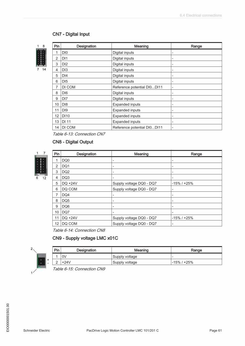
CN7 - Digital Input
Pin Designation Meaning Range1 DI0 Digital inputs -2 DI1 Digital inputs -3 DI2 Digital inputs -4 DI3 Digital inputs -5 DI4 Digital inputs -6 DI5 Digital inputs -7 DI COM Reference potential DI0...DI11 -8 DI6 Digital inputs -9 DI7 Digital inputs -
10 DI8 Expanded inputs -11 DI9 Expanded inputs -12 DI10 Expanded inputs -13 DI 11 Expanded inputs -14 DI COM Reference potential DI0...DI11 -
Table 6-13: Connection CN7
CN8 - Digital Output
Pin Designation Meaning Range1 DQ0 - -2 DQ1 - -3 DQ2 - -4 DQ3 - -5 DQ +24V Supply voltage DQ0 - DQ7 -15% / +25%6 DQ COM Supply voltage DQ0 - DQ7 -7 DQ4 - -8 DQ5 - -9 DQ6 - -
10 DQ7 - -11 DQ +24V Supply voltage DQ0 - DQ7 -15% / +25%12 DQ COM Supply voltage DQ0 - DQ7 -
Table 6-14: Connection CN8
CN9 - Supply voltage LMC x01C
Pin Designation Meaning Range1 0V Supply voltage -2 +24V Supply voltage -15% / +25%
Table 6-15: Connection CN9
6.4 Electrical connections
Schneider Electric PacDrive Logic Motion Controller LMC 101/201 C Page 61EIO
0000
0015
01.0
0

CN10 - TM5
Pin Designation Meaning Range1 TM5 + Data line + -2 TM5 GND ground -3 TM5 - Data line - -4 SHLD Shield -
Table 6-16: Connection CN10
TM5 is not active.
CN11 - CAN
Pin Designation Meaning Signal / function1 - Reserved -2 CAN_L Bus line (low) -3 CAN GND - -4 - Reserved -5 - Reserved -6 CAN GND - -7 CAN_H Bus line (high) -8 - Reserved -9 - Reserved -
Table 6-17: Connection CN11
TM5/TM7 modules can only be connected to the SERCOS III bus, this means, theconnection of the TM5/TM7 modules to the PacDrive controller can only occur via aSERCOS III bus interface TM5NS31. A connection of TM5/TM7 modules via CAN busand a CANopen interface module is not supported.CN12 - Master encoder input (Hiperface)The Hiperface connection consists of a standard, differential, digital connection(RS485 = 2 wires), a differential, analog connection (sine- and cosine signal = 4 wires)and a mains connection to supply the encoder (+10V, GND = 2 wires).
Pin Designation Meaning Signal / function1 COS Cosine track -2 REFCOS Reference Signal Cosinus -3 SIN Sinusoidal trace -4 RS485+ Parameter channel + -5 RS485- Parameter channel - -6 REFSIN Reference signal sine -7 - Reserved -8 - Reserved -A Encoder supply (+) - -B GND - -
Table 6-18: Connection CN12 - Master encoder input (Hiperface)
6 Technical data
Page 62 PacDrive Logic Motion Controller LMC 101/201 C Schneider Electric EIO
0000
0015
01.0
0

CN12 - Master encoder input (incremental)
Pin Designation Meaning Signal / function1 Trace B+ - -2 Trace B- - -3 Trace A+ - -4 Trace N+ - -5 Trace N- - -6 Trace A- - -7 - Reserved -8 - Reserved -A Encoder supply (+) - -B GND - -
Table 6-19: Connection CN12 - Master encoder input (incremental)
6.4 Electrical connections
Schneider Electric PacDrive Logic Motion Controller LMC 101/201 C Page 63EIO
0000
0015
01.0
0
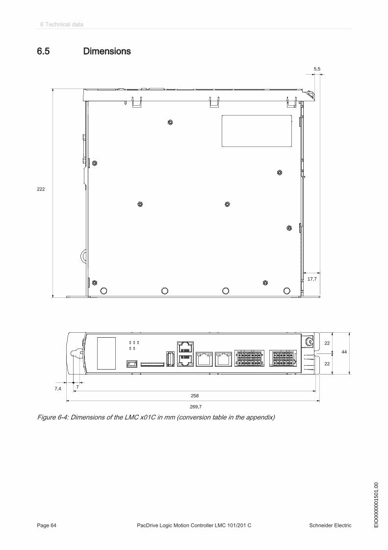
6.5 Dimensions
7,4 7
269,7
258
22
22
44
222
17,7
5,5
Figure 6-4: Dimensions of the LMC x01C in mm (conversion table in the appendix)
6 Technical data
Page 64 PacDrive Logic Motion Controller LMC 101/201 C Schneider Electric EIO
0000
0015
01.0
0

7 Optional module
7.1 Communication Module Realtime Ethernet
7.1.1 General
The communication module realtime Ethernet is an optional module that provides aPROFINET, EtherNet/IP or EtherCAT-Slave interface.
Figure 7-1: Communication module realtime Ethernet - connections
1 Ethernet channel 02 Ethernet channel 1
After installing the optional module, the controller will automatically detect the module.Configure the module after it was detected via the PLC configuration in SoMachineMotion EPAS.
7.1 Communication Module Realtime Ethernet
Schneider Electric PacDrive Logic Motion Controller LMC 101/201 C Page 65EIO
0000
0015
01.0
0
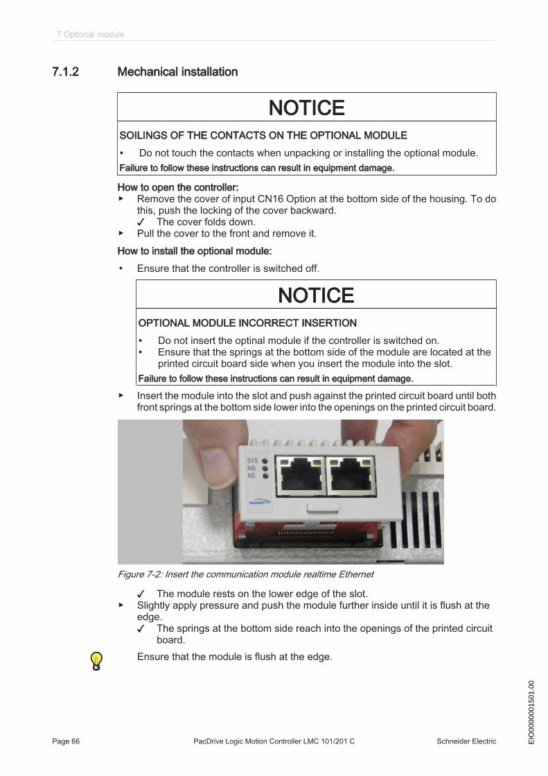
7.1.2 Mechanical installation
NOTICESOILINGS OF THE CONTACTS ON THE OPTIONAL MODULE
• Do not touch the contacts when unpacking or installing the optional module.Failure to follow these instructions can result in equipment damage.
How to open the controller:▶ Remove the cover of input CN16 Option at the bottom side of the housing. To do
this, push the locking of the cover backward.The cover folds down.
▶ Pull the cover to the front and remove it.How to install the optional module:
▪ Ensure that the controller is switched off.
NOTICEOPTIONAL MODULE INCORRECT INSERTION
• Do not insert the optinal module if the controller is switched on.• Ensure that the springs at the bottom side of the module are located at the
printed circuit board side when you insert the module into the slot.Failure to follow these instructions can result in equipment damage.
▶ Insert the module into the slot and push against the printed circuit board until bothfront springs at the bottom side lower into the openings on the printed circuit board.
Figure 7-2: Insert the communication module realtime Ethernet
The module rests on the lower edge of the slot.▶ Slightly apply pressure and push the module further inside until it is flush at the
edge.The springs at the bottom side reach into the openings of the printed circuitboard.
Ensure that the module is flush at the edge.
7 Optional module
Page 66 PacDrive Logic Motion Controller LMC 101/201 C Schneider Electric EIO
0000
0015
01.0
0
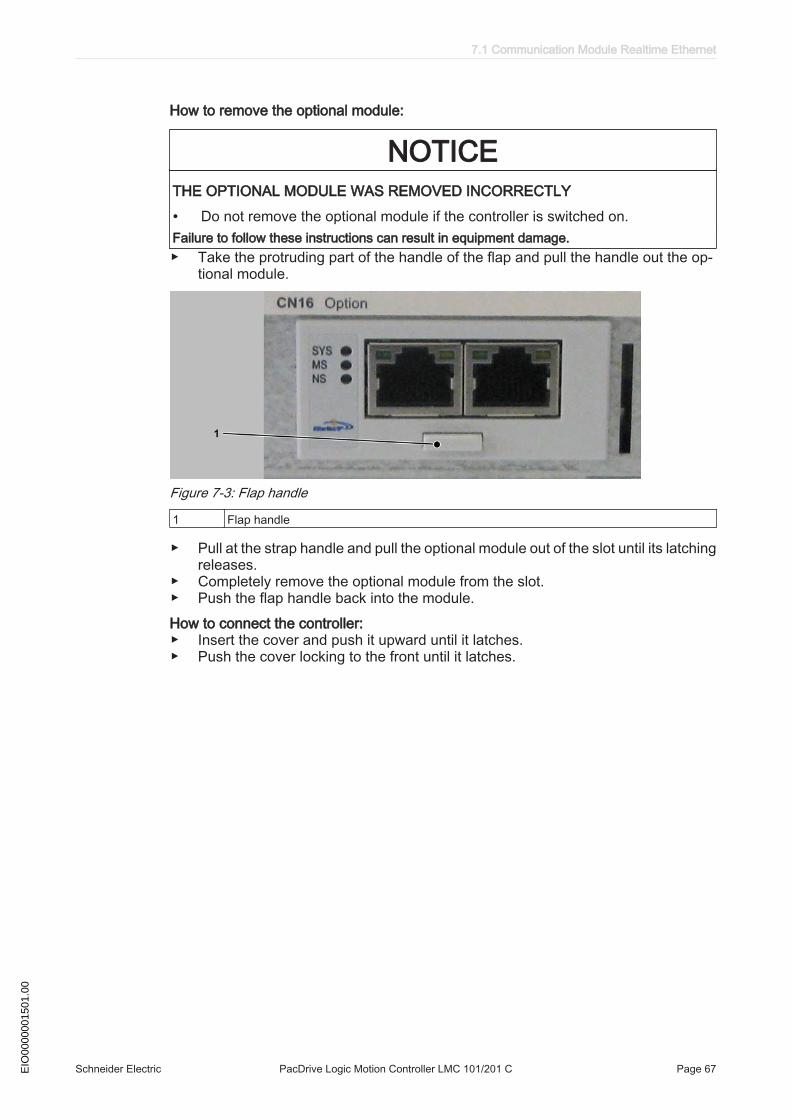
How to remove the optional module:
NOTICETHE OPTIONAL MODULE WAS REMOVED INCORRECTLY
• Do not remove the optional module if the controller is switched on.Failure to follow these instructions can result in equipment damage.▶ Take the protruding part of the handle of the flap and pull the handle out the op‐
tional module.
Figure 7-3: Flap handle
1 Flap handle
▶ Pull at the strap handle and pull the optional module out of the slot until its latchingreleases.
▶ Completely remove the optional module from the slot.▶ Push the flap handle back into the module.How to connect the controller:▶ Insert the cover and push it upward until it latches.▶ Push the cover locking to the front until it latches.
7.1 Communication Module Realtime Ethernet
Schneider Electric PacDrive Logic Motion Controller LMC 101/201 C Page 67EIO
0000
0015
01.0
0

7.1.3 Electrical connections
Connection details Communication Module Realtime Ethernet
8
NI
P
8
NI
P
1
NI
P
1
NI
P
1 2
Figure 7-4: Connection details Realtime Ethernet
1 Ethernet channel 02 Ethernet channel 1
Pin Designation Meaning1 Tx+ Transmit Data +2 Tx- Transmit Data -3 Rx+ Receive Data +4 TERM -5 TERM6 Rx- Receive Data -7 TERM -8 TERM
Table 7-1: Ethernet outlet
7 Optional module
Page 68 PacDrive Logic Motion Controller LMC 101/201 C Schneider Electric EIO
0000
0015
01.0
0
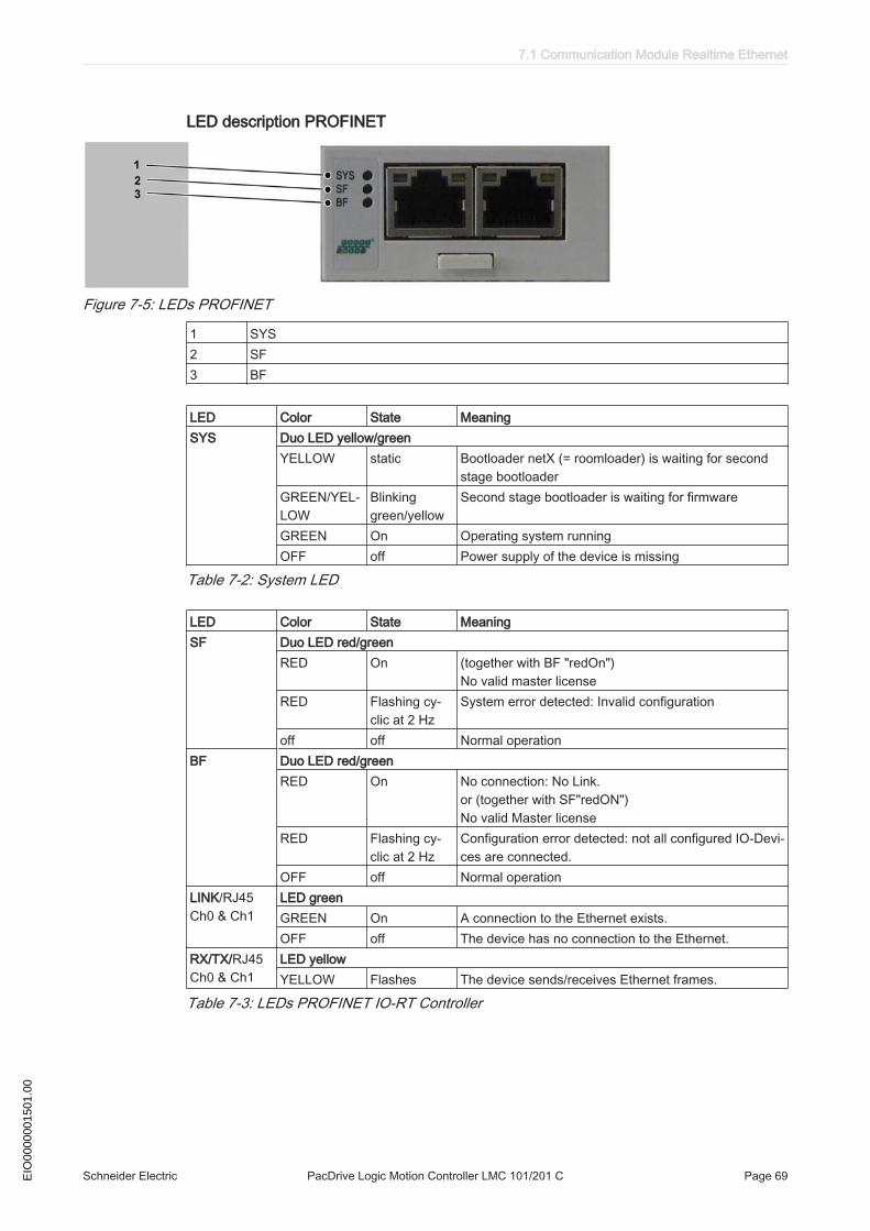
LED description PROFINET
Figure 7-5: LEDs PROFINET
1 SYS2 SF3 BF
LED Color State MeaningSYS Duo LED yellow/green
YELLOW static Bootloader netX (= roomloader) is waiting for secondstage bootloader
GREEN/YEL‐LOW
Blinkinggreen/yellow
Second stage bootloader is waiting for firmware
GREEN On Operating system runningOFF off Power supply of the device is missing
Table 7-2: System LED
LED Color State MeaningSF Duo LED red/green
RED On (together with BF "redOn")No valid master license
RED Flashing cy‐clic at 2 Hz
System error detected: Invalid configuration
off off Normal operationBF Duo LED red/green
RED On No connection: No Link.or (together with SF"redON")No valid Master license
RED Flashing cy‐clic at 2 Hz
Configuration error detected: not all configured IO-Devi‐ces are connected.
OFF off Normal operationLINK/RJ45 Ch0 & Ch1
LED greenGREEN On A connection to the Ethernet exists.OFF off The device has no connection to the Ethernet.
RX/TX/RJ45 Ch0 & Ch1
LED yellowYELLOW Flashes The device sends/receives Ethernet frames.
Table 7-3: LEDs PROFINET IO-RT Controller
7.1 Communication Module Realtime Ethernet
Schneider Electric PacDrive Logic Motion Controller LMC 101/201 C Page 69EIO
0000
0015
01.0
0

LED Color State MeaningSF Duo LED red/green
RED On Watchdog timeout, channel, generic or extended diag‐nostic present; system error detected
RED Flashing cy‐clic at 2 Hz (for3 sec.)
DCP signal service is initiated via the bus
off off Normal operationBF Duo LED red/green
RED On No configuration; or low speed physical link; or no phys‐ical link
RED Flashing cy‐clic at 2 Hz
No data exchange
OFF off Normal operationLINK/RJ45 Ch0 & Ch1
LED greenGREEN On A connection to the Ethernet exists.OFF off The device has no connection to the Ethernet.
RX/TX/RJ45 Ch0 & Ch1
LED yellowYELLOW Flashes The device sends/receives Ethernet frames.
Table 7-4: LEDs PROFINET IO-RT-Device
LED description EtherNet/IP
Figure 7-6: LEDs EtherNet/IP
1 SYS2 MS3 NS
LED Color State MeaningSYS Duo LED yellow/green
YELLOW static Bootloader netX (= roomloader) is waiting for secondstage bootloader
GREEN/YEL‐LOW
Blinkinggreen/yellow
Second stage bootloader is waiting for firmware
GREEN On Operating system runningOFF off Power supply of the device is missing
Table 7-5: System LED
7 Optional module
Page 70 PacDrive Logic Motion Controller LMC 101/201 C Schneider Electric EIO
0000
0015
01.0
0
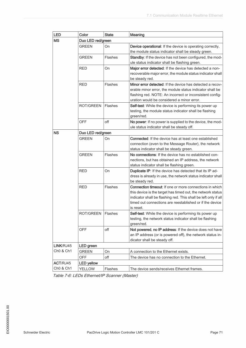
LED Color State MeaningMS Duo LED red/green
GREEN On Device operational: If the device is operating correctly,the module status indicator shall be steady green.
GREEN Flashes Standby: If the device has not been configured, the mod‐ule status indicator shall be flashing green.
RED On Major error detected: If the device has detected a non-recoverable major error, the module status indicator shallbe steady red.
RED Flashes Minor error detected: If the device has detected a recov‐erable minor error, the module status indicator shall beflashing red. NOTE: An incorrect or inconsistent config‐uration would be considered a minor error.
ROT/GREEN Flashes Self-test: While the device is performing its power uptesting, the module status indicator shall be flashinggreen/red.
OFF off No power: If no power is supplied to the device, the mod‐ule status indicator shall be steady off.
NS Duo LED red/greenGREEN On Connected: If the device has at least one established
connection (even to the Message Router), the networkstatus indicator shall be steady green.
GREEN Flashes No connections: If the device has no established con‐nections, but has obtained an IP address, the networkstatus indicator shall be flashing green.
RED On Duplicate IP: If the device has detected that its IP ad‐dress is already in use, the network status indicator shallbe steady red.
RED Flashes Connection timeout: If one or more connections in whichthis device is the target has timed out, the network statusindicator shall be flashing red. This shall be left only if alltimed out connections are reestablished or if the deviceis reset.
ROT/GREEN Flashes Self-test: While the device is performing its power uptesting, the network status indicator shall be flashinggreen/red.
OFF off Not powered, no IP address: If the device does not havean IP address (or is powered off), the network status in‐dicator shall be steady off.
LINK/RJ45 Ch0 & Ch1
LED greenGREEN On A connection to the Ethernet exists.OFF off The device has no connection to the Ethernet.
ACT/RJ45 Ch0 & Ch1
LED yellowYELLOW Flashes The device sends/receives Ethernet frames.
Table 7-6: LEDs Ethernet/IP Scanner (Master)
7.1 Communication Module Realtime Ethernet
Schneider Electric PacDrive Logic Motion Controller LMC 101/201 C Page 71EIO
0000
0015
01.0
0

LED Color State MeaningMS Duo LED red/green
GREEN On Device operational: If the device is operating correctly,the module status indicator shall be steady green.
GREEN Flashes Standby: If the device has not been configured, the mod‐ule status indicator shall be flashing green.
RED On Major error detected: If the device has detected a non-recoverable major error, the module status indicator shallbe steady red.
RED Flashes Minor error detected: If the device has detected a recov‐erable minor error, the module status indicator shall beflashing red. NOTE: An incorrect or inconsistent config‐uration would be considered a minor error.
ROT/GREEN Flashes Self-test: While the device is performing its power uptesting, the module status indicator shall be flashinggreen/red.
OFF off No power: If no power is supplied to the device, the mod‐ule status indicator shall be steady off.
NS Duo LED red/greenGREEN On Connected: If the device has at least one established
connection (even to the Message Router), the networkstatus indicator shall be steady green.
GREEN Flashes No connections: If the device has no established con‐nections, but has obtained an IP address, the networkstatus indicator shall be flashing green.
RED On Duplicate IP: If the device has detected that its IP ad‐dress is already in use, the network status indicator shallbe steady red.
RED Flashes Connection timeout: If one or more connections in whichthis device is the target has timed out, the network statusindicator shall be flashing red. This shall be left only if alltimed out connections are reestablished or if the deviceis reset.
ROT/GREEN Flashes Self-test: While the device is performing its power uptesting, the network status indicator shall be flashinggreen/red.
OFF off Not powered, no IP address: If the device does not havean IP address (or is powered off), the network status in‐dicator shall be steady off.
LINK/RJ45 Ch0 & Ch1
LED greenGREEN On A connection to the Ethernet exists.OFF off The device has no connection to the Ethernet.
ACT/RJ45 Ch0 & Ch1
LED yellowYELLOW Flashes The device sends/receives Ethernet frames.
Table 7-7: LEDs Ethernet/IP Adapter (Slave)
7 Optional module
Page 72 PacDrive Logic Motion Controller LMC 101/201 C Schneider Electric EIO
0000
0015
01.0
0
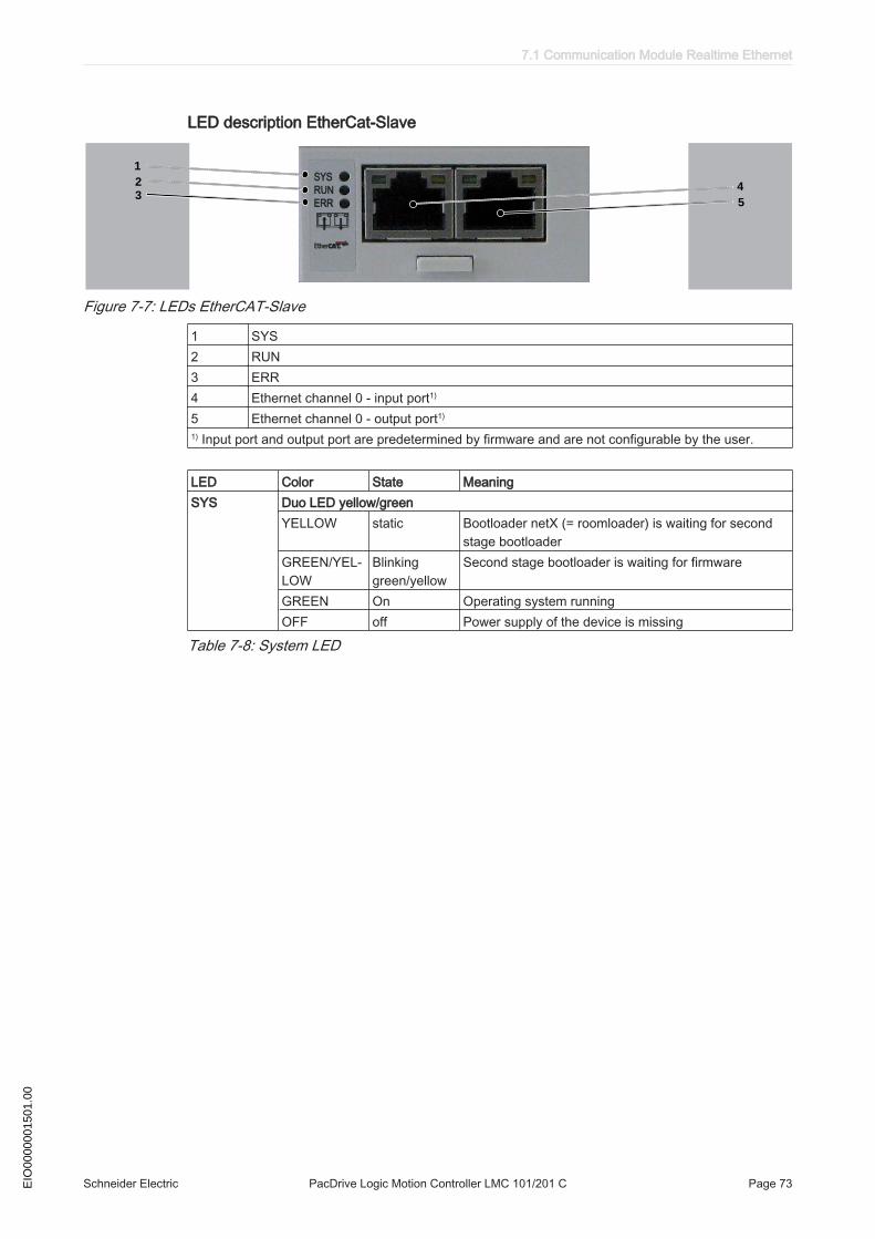
LED description EtherCat-Slave
1
2
34
5
Figure 7-7: LEDs EtherCAT-Slave
1 SYS2 RUN3 ERR4 Ethernet channel 0 - input port1)
5 Ethernet channel 0 - output port1)
1) Input port and output port are predetermined by firmware and are not configurable by the user.
LED Color State MeaningSYS Duo LED yellow/green
YELLOW static Bootloader netX (= roomloader) is waiting for secondstage bootloader
GREEN/YEL‐LOW
Blinkinggreen/yellow
Second stage bootloader is waiting for firmware
GREEN On Operating system runningOFF off Power supply of the device is missing
Table 7-8: System LED
7.1 Communication Module Realtime Ethernet
Schneider Electric PacDrive Logic Motion Controller LMC 101/201 C Page 73EIO
0000
0015
01.0
0
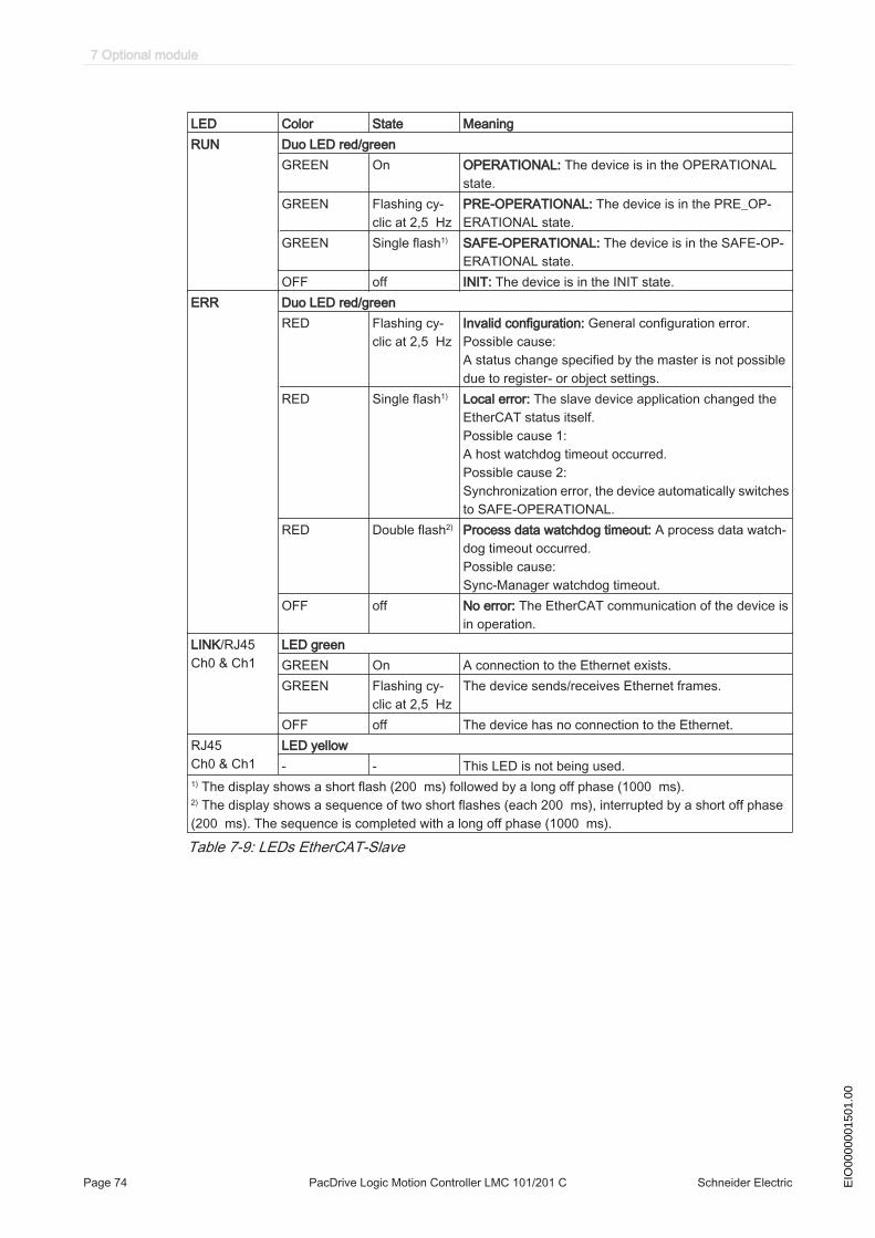
LED Color State MeaningRUN Duo LED red/green
GREEN On OPERATIONAL: The device is in the OPERATIONALstate.
GREEN Flashing cy‐clic at 2,5 Hz
PRE-OPERATIONAL: The device is in the PRE_OP‐ERATIONAL state.
GREEN Single flash1) SAFE-OPERATIONAL: The device is in the SAFE-OP‐ERATIONAL state.
OFF off INIT: The device is in the INIT state.ERR Duo LED red/green
RED Flashing cy‐clic at 2,5 Hz
Invalid configuration: General configuration error.Possible cause:A status change specified by the master is not possibledue to register- or object settings.
RED Single flash1) Local error: The slave device application changed theEtherCAT status itself.Possible cause 1:A host watchdog timeout occurred.Possible cause 2:Synchronization error, the device automatically switchesto SAFE-OPERATIONAL.
RED Double flash2) Process data watchdog timeout: A process data watch‐dog timeout occurred.Possible cause:Sync-Manager watchdog timeout.
OFF off No error: The EtherCAT communication of the device isin operation.
LINK/RJ45 Ch0 & Ch1
LED greenGREEN On A connection to the Ethernet exists.GREEN Flashing cy‐
clic at 2,5 HzThe device sends/receives Ethernet frames.
OFF off The device has no connection to the Ethernet.RJ45 Ch0 & Ch1
LED yellow- - This LED is not being used.
1) The display shows a short flash (200 ms) followed by a long off phase (1000 ms).2) The display shows a sequence of two short flashes (each 200 ms), interrupted by a short off phase(200 ms). The sequence is completed with a long off phase (1000 ms).
Table 7-9: LEDs EtherCAT-Slave
7 Optional module
Page 74 PacDrive Logic Motion Controller LMC 101/201 C Schneider Electric EIO
0000
0015
01.0
0
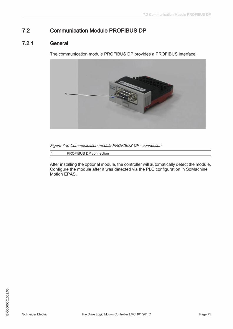
7.2 Communication Module PROFIBUS DP
7.2.1 General
The communication module PROFIBUS DP provides a PROFIBUS interface.
Figure 7-8: Communication module PROFIBUS DP - connection
1 PROFIBUS DP connection
After installing the optional module, the controller will automatically detect the module.Configure the module after it was detected via the PLC configuration in SoMachineMotion EPAS.
7.2 Communication Module PROFIBUS DP
Schneider Electric PacDrive Logic Motion Controller LMC 101/201 C Page 75EIO
0000
0015
01.0
0
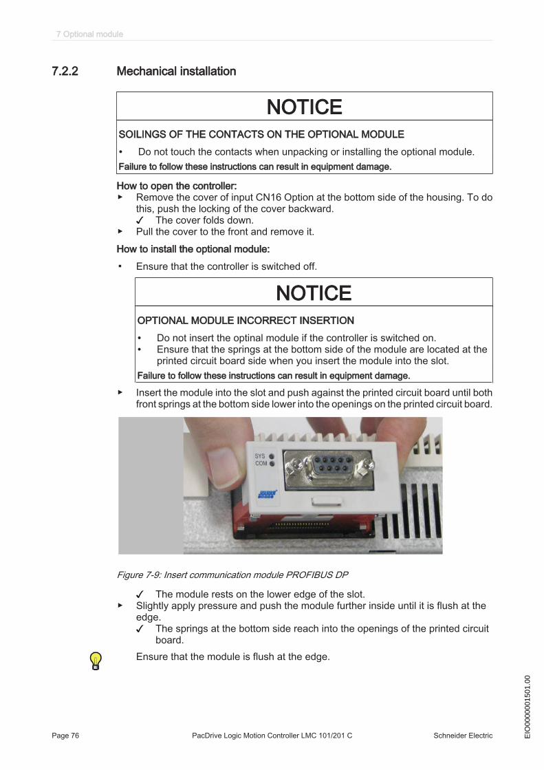
7.2.2 Mechanical installation
NOTICESOILINGS OF THE CONTACTS ON THE OPTIONAL MODULE
• Do not touch the contacts when unpacking or installing the optional module.Failure to follow these instructions can result in equipment damage.
How to open the controller:▶ Remove the cover of input CN16 Option at the bottom side of the housing. To do
this, push the locking of the cover backward.The cover folds down.
▶ Pull the cover to the front and remove it.How to install the optional module:
▪ Ensure that the controller is switched off.
NOTICEOPTIONAL MODULE INCORRECT INSERTION
• Do not insert the optinal module if the controller is switched on.• Ensure that the springs at the bottom side of the module are located at the
printed circuit board side when you insert the module into the slot.Failure to follow these instructions can result in equipment damage.
▶ Insert the module into the slot and push against the printed circuit board until bothfront springs at the bottom side lower into the openings on the printed circuit board.
Figure 7-9: Insert communication module PROFIBUS DP
The module rests on the lower edge of the slot.▶ Slightly apply pressure and push the module further inside until it is flush at the
edge.The springs at the bottom side reach into the openings of the printed circuitboard.
Ensure that the module is flush at the edge.
7 Optional module
Page 76 PacDrive Logic Motion Controller LMC 101/201 C Schneider Electric EIO
0000
0015
01.0
0
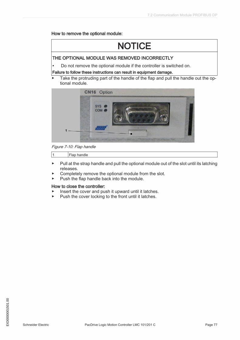
How to remove the optional module:
NOTICETHE OPTIONAL MODULE WAS REMOVED INCORRECTLY
• Do not remove the optional module if the controller is switched on.Failure to follow these instructions can result in equipment damage.▶ Take the protruding part of the handle of the flap and pull the handle out the op‐
tional module.
Figure 7-10: Flap handle
1 Flap handle
▶ Pull at the strap handle and pull the optional module out of the slot until its latchingreleases.
▶ Completely remove the optional module from the slot.▶ Push the flap handle back into the module.How to close the controller:▶ Insert the cover and push it upward until it latches.▶ Push the cover locking to the front until it latches.
7.2 Communication Module PROFIBUS DP
Schneider Electric PacDrive Logic Motion Controller LMC 101/201 C Page 77EIO
0000
0015
01.0
0
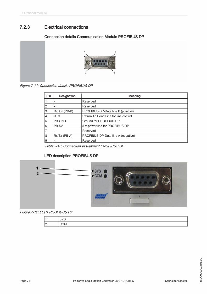
7.2.3 Electrical connections
Connection details Communication Module PROFIBUS DP
Figure 7-11: Connection details PROFIBUS DP
Pin Designation Meaning1 - Reserved2 - Reserved3 Rx/Tx+(PB-B) PROFIBUS-DP-Data line B (positive)4 RTS Return To Send Line for line control5 PB-GND Ground for PROFIBUS-DP6 PB-5V 5 V power line for PROFIBUS-DP7 - Reserved8 Rx/Tx-(PB-A) PROFIBUS-DP-Data line A (negative)9 - Reserved
Table 7-10: Connection assignment PROFIBUS DP
LED description PROFIBUS DP
Figure 7-12: LEDs PROFIBUS DP
1 SYS2 COM
7 Optional module
Page 78 PacDrive Logic Motion Controller LMC 101/201 C Schneider Electric EIO
0000
0015
01.0
0

LED Color State MeaningSYS Duo LED yellow/green
YELLOW static Bootloader netX (= roomloader) is waiting for secondstage bootloader
GREEN/YEL‐LOW
Blinkinggreen/yellow
Second stage bootloader is waiting for firmware
GREEN On Operating system runningOFF off Power supply of the device is missing
Table 7-11: System LED
LED Color State MeaningcifX with 1 Communication LED (current Hardware Revision)COM Duo LED red/green
GREEN Flashing acy‐clic
No configuration or stack error detected
GREEN Flashing cy‐clic
Profibus is configured, but bus communication is not yetreleased from the application
GREEN On Communication to all Slaves is establishedRED Flashing cy‐
clicCommunication to at least one Slave is disconnected.
RED On Communication to one/all Slaves is disconnected
Table 7-12: LEDs PROFIBUS DP Master - 1 Communication LED (current Hardware Revision)
LED Color State MeaningcifX with 1 Communication LED (current Hardware Revision)COM Duo LED red/green
GREEN On RUN, cyclic communicationRED Flashing cy‐
clicSTOP, no communication, connection error detected
RED Flashing acy‐clic
Not configured
Table 7-13: LEDs PROFIBUS DP Slave - 1 Communication LED (current Hardware Revision)
7.2 Communication Module PROFIBUS DP
Schneider Electric PacDrive Logic Motion Controller LMC 101/201 C Page 79EIO
0000
0015
01.0
0

8 Appendix
8.1 Contact addresses
Schneider Electric Automation GmbHSchneiderplatz 197828 Marktheidenfeld, GermanyPhone: +49 (0) 9391 / 606 - 0Fax: +49 (0) 9391 / 606 - 4000Email: [email protected]: www.schneider-electric.com
Machine Solution Service97828 Marktheidenfeld, GermanyPhone: +49 (0) 9391 / 606 - 3265Fax: +49 (0) 9391 / 606 - 3340eMail: automation.support.de@schneider-elec‐tric.comInternet: www.schneider-electric.com
See the homepage (www.schneider-electric.com) for additional contact addresses.
8.2 Product training courses
Schneider Electric offers a number of product training courses.Our training instructors will help you take advantage of the extensive possibilities of‐fered by the system.
See the homepage (www.schneider-electric.com) for further information and our cur‐rent seminar schedule.
8.3 Disposal
The components consist of different materials, which can be re-used and must bedisposed of separately. The packaging cannot be returned to the manufacturer.
▶ Dispose of the packaging in accordance with the relevant national regulations.▶ Dispose of the packaging at the disposal sites provided for this purpose.▶ Dispose of controller in accordance with the applicable national regulations.
8 Appendix
Page 80 PacDrive Logic Motion Controller LMC 101/201 C Schneider Electric EIO
0000
0015
01.0
0

8.4 Units and conversion tables
8.4.1 Length
in ft yd m cm mmin - / 12 / 36 * 0.0254 * 2.54 * 25.4ft * 12 - /3 * 0.30479 * 30.479 * 304.79yd * 36 * 3 - * 0.9144 * 91.44 * 914.4m / 0.0254 / 0.30479 / 0.9144 - *100 * 1000cm / 2.54 / 30.479 / 91.44 / 100 - * 10mm / 25.4 / 304.79 / 914.4 / 1000 / 10 -
8.4.2 Mass
lb oz slug 0.22 kg glb - * 16 * 0.03108095 * 0.4535924 * 453.5924oz / 16 - * 1.942559*10-3 * 0.02834952 * 28.34952slug / 0.03108095 / 1.942559*10-3 - * 14.5939 * 14593.90.22 kg / 0.45359237 / 0.02834952 / 14.5939 - * 1000g / 453.59237 / 28.34952 / 14593.9 / 1000 -
8.4.3 Force
lb oz p dyne Nlb - * 16 * 453.55358 * 444822.2 * 4.448222oz / 16 - * 28.349524 * 27801 * 0.27801p / 453.55358 / 28.349524 - * 980.7 * 9.807*10-3
dyne / 444822.2 / 27801 / 980.7 - / 100*103
N / 4.448222 / 0.27801 / 9.807*10-3 * 100*103 -
8.4.4 Power
HP WHP - * 746W / 746 -
8.4.5 Rotation
min-1(rpm) rad/s deg./smin-1(rpm) - * π / 30 * 6rad/s * 30 / π - * 57.295deg./s / 6 / 57.295 -
8.4 Units and conversion tables
Schneider Electric PacDrive Logic Motion Controller LMC 101/201 C Page 81EIO
0000
0015
01.0
0
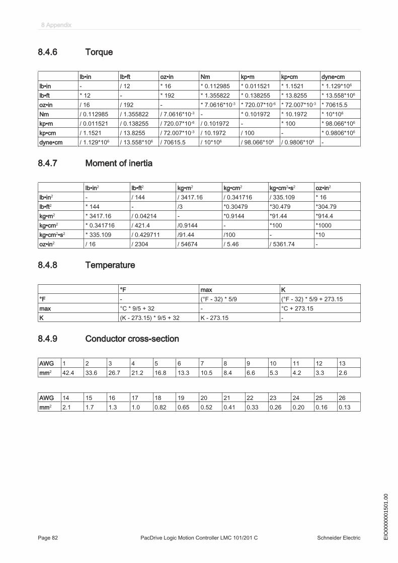
8.4.6 Torque
lb•in lb•ft oz•in Nm kp•m kp•cm dyne•cmlb•in - / 12 * 16 * 0.112985 * 0.011521 * 1.1521 * 1.129*106
lb•ft * 12 - * 192 * 1.355822 * 0.138255 * 13.8255 * 13.558*106
oz•in / 16 / 192 - * 7.0616*10-3 * 720.07*10-6 * 72.007*10-3 * 70615.5Nm / 0.112985 / 1.355822 / 7.0616*10-3 - * 0.101972 * 10.1972 * 10*106
kp•m / 0.011521 / 0.138255 / 720.07*10-6 / 0.101972 - * 100 * 98.066*106
kp•cm / 1.1521 / 13.8255 / 72.007*10-3 / 10.1972 / 100 - * 0.9806*106
dyne•cm / 1.129*106 / 13.558*106 / 70615.5 / 10*106 / 98.066*106 / 0.9806*106 -
8.4.7 Moment of inertia
lb•in2 lb•ft2 kg•m2 kg•cm2 kg•cm2•s2 oz•in2
lb•in2 - / 144 / 3417.16 / 0.341716 / 335.109 * 16lb•ft2 * 144 - /3 *0.30479 *30.479 *304.79kg•m2 * 3417.16 / 0.04214 - *0.9144 *91.44 *914.4kg•cm2 * 0.341716 / 421.4 /0.9144 - *100 *1000kg•cm2•s2 * 335.109 / 0.429711 /91.44 /100 - *10oz•in2 / 16 / 2304 / 54674 / 5.46 / 5361.74 -
8.4.8 Temperature
°F max K°F - (°F - 32) * 5/9 (°F - 32) * 5/9 + 273.15max °C * 9/5 + 32 - °C + 273.15K (K - 273.15) * 9/5 + 32 K - 273.15 -
8.4.9 Conductor cross-section
AWG 1 2 3 4 5 6 7 8 9 10 11 12 13mm2 42.4 33.6 26.7 21.2 16.8 13.3 10.5 8.4 6.6 5.3 4.2 3.3 2.6
AWG 14 15 16 17 18 19 20 21 22 23 24 25 26mm2 2.1 1.7 1.3 1.0 0.82 0.65 0.52 0.41 0.33 0.26 0.20 0.16 0.13
8 Appendix
Page 82 PacDrive Logic Motion Controller LMC 101/201 C Schneider Electric EIO
0000
0015
01.0
0
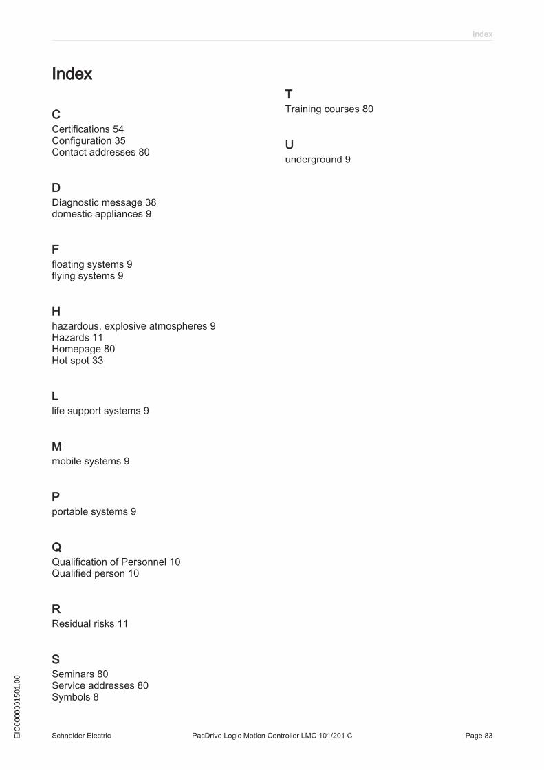
Index
CCertifications 54Configuration 35Contact addresses 80
DDiagnostic message 38domestic appliances 9
Ffloating systems 9flying systems 9
Hhazardous, explosive atmospheres 9Hazards 11Homepage 80Hot spot 33
Llife support systems 9
Mmobile systems 9
Pportable systems 9
QQualification of Personnel 10Qualified person 10
RResidual risks 11
SSeminars 80Service addresses 80Symbols 8
TTraining courses 80
Uunderground 9
Index
Schneider Electric PacDrive Logic Motion Controller LMC 101/201 C Page 83EIO
0000
0015
01.0
0