operating manual and parts list - the home depot · pdf fileswitch settings set at the factory...
TRANSCRIPT
OPERATING MANUAL AND PARTS LIST MODEL GR309EDV ELECTRIC COMPRESSOR
www.grip-rite.com

TABLE OF CONTENTS
Table of Contents .......................................................................... 1
Safety Symbols ............................................................................. 2
Safety Instructions........................................................................ 3
Specifications................................................................................ 5
Compressor Description .............................................................. 6
Compressor Parts Description..................................................... 7
Set Up............................................................................................. 8
Operation ....................................................................................... 9
Maintenance ................................................................................ 10
GR309EDV Compressor Schematic ......................................... 11
GR309EDV Compressor Parts List - Tank/Frame ..................... 12
GR309EDV Compressor Schematic - Pump ............................. 14
GR309EDV Compressor Parts List - Pump ............................... 15
Troubleshooting .......................................................................... 16
Storage......................................................................................... 19
Warranty....................................................................................... 20
WARNING
This manual contains important safety and operating instructions that must be followed.
You must read and understand this manual before operating this compressor. Failure
to follow all instructions can result in serious injury to operator and bystanders, or
damage to compressor and attachments.
1

SAFETY SYMBOLS
The safety symbols used on the compressor’s safety labels and in this manual provide an
important visual reminder of basic safety rules, and the hazards that may arise if all safety and
operating instructions are not followed. Make sure you understand the meaning of each of
these symbols, and protect yourself and others by obeying all safety and operating instructions
on warning labels and in this manual.
SYMBOL DESCRIPTION
SAFETY ALERT SYMBOL Calls attention to important safety information and provides an alert to potential safety hazards.
HOT SURFACE HAZARD Hot surfaces can cause serious burn injury if touched. Let unit cool before handling.
MOVING PARTS/ENTANGLEMENT HAZARD Contact with moving parts can cause serious injury. Keep guards and protective covers in place.
INHALATION HAZARD Compressed air can contain carbon monoxide or other harmful gases. Do not use compressor to provide air for breathing.
BURST HAZARD Over-pressurization caused by tampering with controls can cause serious injury or death from explosion.
SHOCK HAZARD Contact with live electrical components can cause shock, serious injury, or death from electrocution. Use a properly grounded power source.
EXPLOSION HAZARD Electrical sparks from unit can ignite flammable liquids and vapors. Use compressor in a well ventilated area free from explosive vapors.
FIRE HAZARD Keep compressor 20’ feet away from spray area when spraying flammable materials. Operate unit away from obstructions that could block ventilation.
HIGH PRESSURE AIR HAZARD Release of pressurized air can cause serious injury if directed against body. Never use air pressure higher than recommended for tool or accessory.
2

SAFETY INSTRUCTIONS
WEAR ANSI Z87.1 (In Canada, CSA Z94.3-99) APPROVED EYE PROTECTION - Always wear approved eye protection equipment that provides both front and side eye protection when operating or servicing the compressor. DO NOT EXCEED MAXIMUM RECOMMENDED OPERATING PRESSURE OF AIR-POWERED TOOLS OR OTHER EQUIPMENT BEING USED - Spray guns and other low to medium pressure equipment can burst, causing serious injury to user and bystanders. Read and follow all manufacturers' pressure recommendations before connecting tools, sprayers, or other equipment to compressor. Use extreme care when using the compressor with tires, inner tubes, and other inflatables, as excessive pressure or rapid inflation can cause these items to burst. DO NOT OPERATE IF FLAMMABLE VAPORS ARE PRESENT - The electric motor and pressure switch may produce sparks, which can ignite flammable vapors and cause fire or explosion. Flammable vapors from gasoline, solvents, adhesives, and other chemicals may drift some distance from the source, or build up in low areas. Operate the compressor only in well-ventilated areas that are free of flammable vapors. DO NOT TOUCH COMPRESSOR MOTOR, HEAD, OR TUBING WHEN UNIT IS OPERATING - Normal compressor operation will cause tubing and other components to become extremely hot. Contact with hot parts can cause serious burns. Allow unit to cool before handling or performing service. NEVER DIRECT COMPRESSED AIR AT ANY BODY PARTS - Compressed air can penetrate skin, or force dirt and debris into eyes, causing serious injury. Never place hands or body parts over the air discharge opening of a pressurized nozzle or fitting. Use care when connecting and disconnecting air hose to attachments, pneumatic tools, and other air-powered devices. KEEP FLAMMABLE SPRAYS AWAY FROM SPARKS AND OTHER SOURCES OF IGNITION - Spraying flammable liquids such as oil-base paints, sealers, and finishes near sparks, open flame, and other sources of ignition such as pilot lights, appliances, water heaters, furnaces, etc. can result in explosion and fire. Turn off all pilot lights, and avoid using electrical appliances, heaters, torches, and other equipment that may produce sparks or flame. Keep compressor as far away from spraying area as possible by using an air hose of sufficient length to prevent spray mist from being ignited by electrical sparks from compressor operation. DO NOT OPERATE IN THE RAIN OR IN WET AREAS - Operating an electric compressor in wet conditions can result in severe shock or electrocution. Operate only in dry conditions, using a properly grounded power outlet that conforms to local and national electrical code requirements. An outlet with ground-fault circuit interrupter (GFCI) protection is recommended for use outdoors or in garages, and may be required by local electrical codes.
3

SAFETY INSTRUCTIONS DO NOT TAMPER WITH COMPRESSOR PRESSURE SWITCH SETTINGS - The pressure switch settings set at the factory provide the maximum safe operating pressure recommended for this compressor. Altering these settings can result in over-pressurization, risk of tank, hose, and pneumatic equipment failure, and serious injury to operator and bystanders. USE AIR HOSE RATED FOR 150 PSI OR GREATER - Air hose must be rated to safely handle maximum compressor pressure. Air hose that does not meet minimum pressure requirements can rupture, releasing high pressure air. Replace a cracked or leaking air hose immediately to prevent serious injury from contact with high pressure air streams. SHUT OFF COMPRESSOR AND RELIEVE TANK PRESSURE BEFORE SERVICING UNIT – Never perform service or maintenance on any part of the compressor while the unit is running or tanks are pressurized. Open tank drains slowly to allow air to escape, and keep clear of air stream. DO NOT MODIFY COMPRESSOR – Altering the compressor in any way may create a serious safety hazard, and result in serious injury to operator and bystanders. If compressor does not work properly, stop using unit immediately. Return unit to an authorized service center for repairs if problem cannot be remedied by following troubleshooting instructions in this manual. DO NOT USE COMPRESSED AIR FROM THE UNIT FOR BREATHING PURPOSES - Air produced by this compressor may contain poisonous exhaust gases from the engine, and is not suitable for breathing purposes. DO NOT LEAVE COMPRESSOR RUNNING UNATTENDED - Shut compressor off when done, and disconnect air hoses to prevent unauthorized use of compressor. Drain air tanks if unit is to be stored or transported. CONNECT COMPRESSOR POWER CORD ONLY TO A PROPERLY GROUNDED POWER OUTLET USING AN APPROVED 3-PRONG GROUNDED EXTENSION CORD - Using an improperly grounded outlet or extension cord can result in shock or electrocution. Electrical wiring, outlets, extension cords, and current protection devices such as fuses and circuit breakers must meet local electrical and safety codes, as well the requirements of the National Electrical Code. A ground-fault circuit interrupter (GFCI) device may be required for compressor use outdoors, in garages, and in damp locations. USE AN EXTENSION CORD THAT IS PROPERLY SIZED - Using an undersize cord can result in overheating of cord and short-circuiting, resulting in fire and damage to property. Use a UL-listed extension cord rated to safely handle the power requirements of the compressor.
Cord Length Wire Gauge Size Up to 25 ft. 12 ga. Up to 100 ft. 10 ga. Up to 150 ft. 8 ga. Up to 250 ft. 6 ga.
4

SPECIFICATIONS
DESCRIPTION SPECIFICATIONS Motor
Horsepower Running/Peak 1.5/3.0
Motor 115/230V 1 Ph 17/8.5 A
Capacity
Tanks 2
Air Storage Capacity 9 Gallons
Maximum Air Pressure 135 PSI
CFM 7.2 cfm @ 100 PSI
Pressure Switch Settings
Pressure Switch - ON 100 PSII
Pressure Switch - OFF 130 PSI
Compressor Pump
Cylinders 2
Compression Stage 1
Lubrication Splash
Oil Type Non-detergent Mineral Oil
SAE 10W - 30W
ISO 32 - 100
Crankcase Aluminum
Bearings Ball
Cylinders Cast Iron
Valves Stainless Steel
Head Aluminum
Filter Canister
Dimensions
Weight 140 Lbs.
Shipping Weight 162 Lbs.
Size ( L X W X H) 46" X 19" X 24"
5

COMPRESSOR DESCRIPTION
6

COMPRESSOR PARTS DESCRIPTION
KEY DESCRIPTION FUNCTION 1 3 H.P. Electric Motor Provides power to run compressor pump
2 Overload Reset Button Resets motor when overload occurs
3 Twin Storage Tanks Stores compressed air
4 No Flat Tire Semi-pneumatic tire allows easy rolling
5 Rubber Footing Rubber feet reduce vibration
6 Crankcase fill plug Used to fill pump crankcase
7 Compressor Drain Tube Allows easy draining of compressor crankcase
8 Oil Level Sight Glass Indicates oil level in pump crankcase
9 Tank Drain Cocks Allow tanks to be drained of moisture
10 Rubber Hand Grips Provides secure grip for comfortable handling
11 On-Off Switch Lever Turns compressor on and off
12 Switch Box/Power Cord Contains on-off switch and power cord
13 Quick Connect Fittings Allows quick connection of air hoses
14 Compressor Air Intake Filter Keeps dirt and debris out of compressor
15 Belt Guard Guards V-belt and pulleys
16 Safety Valve Releases excessive air pressure from tank
17 Tank Air Pressure Gauge Indicates air pressure in storage tanks
18 Regulator Control Knob Adjusts output air pressure setting.
19 Air Outlet Pressure Gauge Indicates air pressure at air outlet fittings
7

SET UP PROCEDURE
WARNING:
Before being operated with pressurized tanks for the first time, your new compressor requires a simple set-up procedure that will help your unit deliver years of trouble-free service. Failure to follow all initial set-up instructions may result in serious damage to your compressor, property damage, or serious injury to operator and bystanders. Do not allow compressor to pressurize tanks until all set-up steps have been performed.
1. Read the manual and all warning labels on the unit.
2. Check compressor oil level, and fill as needed. (See #9 below)
3. Open the tank drain cocks (A), or outlet valve. 4. Start the compressor (see page 9), and run the
compressor for 20 minutes with drain cock open to lubricate the bearings and pistons.
5. After 20 minutes, close the drain valve or outlet valve.
6. Compressor is now ready for normal, pressurized operation.
7. After first 24 hours of operation, check V-belt tension. Correct tension setting is 1/2” of slack when measured at midpoint between pulleys.
8. Check bolts and nuts periodically and tighten when necessary.
9. Check oil level at sight glass (B). Oil level must be maintained between “L” (Low) and “H” (High) indicator lines. To add oil, remove oil filler plug (C) and fill until sight glass shows proper level. Change oil after first 100 hours of operation. Add non-detergent mineral oil to compressor.
10. Use chart below for correct viscosity: Air Temperature Viscosity 3 – 32° F (16 - 0° C) SAE 10W (ISO 32) 34 – 79° F (1 - 26° C) SAE 20W (ISO 68) 80° F & Up (2° C) SAE 30W (ISO 100)
11. Replace oil filler plug before starting compressor.
8

OPERATION
STARTING COMPRESSOR Pre-starting Checklist: Always check and correct before starting:
Check unit for missing parts or damage. Check for loose nuts and bolts. Check drain cocks and close if open. Check compressor oil level.
1. Move On/Off lever (A) to the "OFF" position. 2. Plug the power cord into the power
receptacle. 3. Move On/Off lever (A) to the "ON" position. 4. Leave compressor in “ON” position while in
use. 5. Adjust outlet air pressure to desired setting by
turning pressure regulator knob “B.” Turn knob clockwise (+) to increase air pressure, counterclockwise (-) to decrease air pressure. Outlet air pressure is indicated by gauge (C). Tank pressure is indicated by gauge (D)
6. Connect air hoses to quick-connect fittings (E) using a male quick-connect fitting. To connect air hose, push back outer ring on compressor fitting, insert male hose connector, and release ring. To release air hose, push hose fitting in, push back outer ring on compressor fitting, and pull male hose connector out.
7. To stop compressor, move On/Off lever (A) to the "OFF" position. DO NOT stop compressor by unplugging power cord.
WARNING
High pressure air will escape when hose is disconnected. Keep face away from fittings to prevent dirt and debris from being blown into eyes. Always wear safety glasses with side shields to protect eyes when using compressor.
9

MAINTENANCE
DANGER
Never perform maintenance on the compressor when it is running. Always place On/Off switch in “OFF” position, disconnect air hoses, drain air tanks, and allow unit to cool first. Performing service procedures on a compressor with pressurized tanks, or with On-Off switch in the “ON” position, can result in serious injury.
COMPRESSOR MAINTENANCE SCHEDULE
Interval Maintenance Required
Check compressor pump oil level, and fill as needed.
Drain moisture from tanks daily. Open drain slowly and let air pressure bleed down gradually before opening drain valve completely.
Perform a visual inspection of compressor. Make sure belt guard is in place, and all components are in good condition.
Daily
Check for unusual noise or vibration during operation, and have problem corrected. Contact your Grip-Rite dealer for service.
Check intake air filters and clean with soapy water if necessary. Rinse and allow to dry before use. Replace filter if worn or damaged.
Check Pressure Relief Valve for proper operation. With tank pressurized, pull on Pressure Relief Valve ring. Air must exhaust when ring is pulled. Release ring - air must stop exhausting when ring is released.
Check V-belt for damage or wear, and replace if necessary.
Clean dust and debris from cylinder heads, fan blades, intercooler, and air tanks.
Weekly
Check for leaks, cracks, or corrosion on tank, fittings, and tubing. Discontinue use of equipment if leaks or other major problems are found, and repair unit before placing back into service.
Change compressor oil and air filter.
Clean/blow off compressor pump fins and motor.
Check for air leaks at connections, and tighten fittings if necessary.
Check tank for cracks, corrosion, leaks, or other damage. Never use a compressor with a damaged tank.
3 Months/ 300 Hours
Check warning labels for legibility, and replace if necessary. Contact your Grip-Rite dealer for replacement labels.
Belt Replacement/Adjustment 1. Shut off compressor and open drain cock to relieve pressure. 2. Remove belt guard 3. Belt Replacement: Loosen motor bolts and slide motor toward compressor head to allow belt to be
removed. Install new belt. 4. Belt Adjustment: Loosen motor bolts and move motor to provide recommended tension as shown on
page 8. 5. Make sure pulleys are aligned properly by placing a straight edge against pulleys. 6. Tighten motor bolts securely, and recheck alignment. 7. Replace belt guard 8. Close drain cock and restart compressor. 9. Check belt tension after first 20 hours of operation, then check monthly.
10
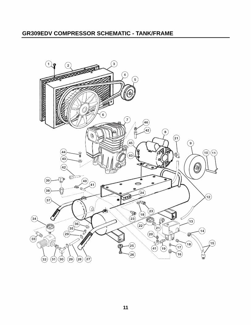
GR309EDV COMPRESSOR SCHEMATIC - TANK/FRAME
11

GR309EDV COMPRESSOR PARTS LIST - TANK/FRAME
REF NO. DESCRIPTION QTY. PART #
1 Screw 4 GRCE2200
2 Belt Guard Cover 1 GRCE1860
3 Belt Guard Base 1 GRCE1850
4 Belt 1 GRCE1890
5 Pulley 1 GRCE2280
6 Flywheel 1 GRCE1930
7 Complete Pump with Flywheel 1 GRCE2250
8 Motor 1 GRCE2240
9 Wheel 1 GRCE1620
10 Axle 1 GRCE1030
11 Cotter Pin 2 GRCE1110
12 Electric Cord - 40" 1 GRCE1840
13 Pressure Switch 1 GRCE2270
14 Box Connector - Straight 1 GRCE1810
15 Power Cord with Plug 1 GRCE1820
16 Bushing 1 GRCE1190
17 Nipple 1 GRCE1220
18 Pipe Plug 2 GRCE1870
19 Safety Valve 1 GRCE1590
20 Pressure Switch Relief Valve 1 GRCE2260
21 Box Connector - 90° 2 GRCE1830
22 Gauge 1 GRCE2150
23 Quick Coupler 2 GRCE1390
24 Triple Manifold 1 GRCE1450
25 Rubber Pad 4 GRCE1040
26 Screw 4 GRCE1460
27 Handle Grip 2 GRCE1050
12

GR309EDV COMPRESSOR PARTS LIST - TANK/FRAME
REF NO. DESCRIPTION QTY. PART #
28 Rubber Hose - 3/8" 0.85 GRCE1090
29 Screw Clamp - 3/8" 2 GRCE1080
30 Elbow 1 GRCE1280
31 Bushing 1 GRCE1180
32 Regulator 1 GRCE1560
33 Nipple 1 GRCE1240
34 Gauge 1 GRCE2160
35 Hose Barb 1 GRCE1250
36 Washer - 1/2" 1 GRCE2230
37 Tank Assembly 1 GRCE2290
38 Check Valve 1 GRCE1360
39 Elbow 1 GRCE1290
40 Elbow 1 GRCE1260
Tubing - 1/4" 1.1 GRCE1100
Compression Nut - 1/4" 2 GRCE1300
Compression Ring - 1/4" 2 GRCE1320 41
Compression Insert - 1/4" 2 GRCE1330
42 Delivery Tube with Fittings 1 GRCE2170
Flat Washer - 1/4" 8 GRCE2220 43
Lock Washer - 5/16" 8 GRCE2210
44 Bolt - 5/16" x 1-1/2" 4 GRCE2190
45 Bolt - 5/16" x 7/8" 4 GRCE2180
46 Straight Connector 1 GRCE1880
13

GR309EDV COMPRESSOR SCHEMATIC - PUMP
14

GR309EDV COMPRESSOR PARTS LIST - PUMP
REF # PART # DESCRIPTION QTY
1 Intake Filter Assembly GRCE2120 1
2 Element GRCE1970 1
3 Head GRCE2070 1
4 Cold Start Valve GRCE1910 1
5 Aftercooler GRCE2080 1
6 Valve Plate Assembly GRCE2130 1
7 Cylinder GRCE2050 1
8 Complete Piston
Assembly
GRCE2140 2
9 Ring Set (2 required) GRCE2090 2
10 Connecting Rod GRCE2030 2
11 Crankshaft GRCE2060 1
12 Dipstick GRCE2110 1
13 Sight Gauge GRCE1920 1
14 End Cover GRCE2000 1
15 Crankcase GRCE2040 1
16 Ball Bearing GRCE1980 1
17 Oil Seal GRCE1900 1
18 Bearing Carrier GRCE1990 1
19 Flywheel GRCE1930 1
20 Washer GRCE1960 1
21 Bolt (Left-Hand Thread) GRCE1950 1
22 Lower Cover GRCE2010 1
23 Gasket Set GRCE2100 1
24 Shroud GRCE2020 1
15

TROUBLESHOOTING
PROBLEM CAUSE REMEDY
On/Off switch in OFF position Move switch to ON position
Power cord not plugged in Plug power cord in
Compressor won't start
Power receptacle breaker tripped or fuse blown
Reset breaker or replace fuse.
Drain cock open or loose Close or tighten
Safety relief valve leaks Replace
Open or broken unloader valve Replace
Dirty or plugged air filter Clean or replace as necessary
Low pressure
Air fitting on hose stuck open Repair or replace
Improper oil viscosity Drain and replace oil
Too much oil in crankcase Drain oil to proper level
Compressor overheated Air pressure regulated too high
Restricted air filter Clean or replace air filter
Oil in discharge
Worn piston rings Replace piston rings
Clogged inlet filter Clean or replace as necessary
Dirty compressor, head, cylinder, or intercooler
Clean with compressed air
Operating pressure too high Reduce pressure
Low oil level, or wrong oil used Drain and replace oil
Compressor overheats
Air tool or attachment air consumption exceeds compressor output - compressor run cycle too long
Reduce air consumption requirements
16

TROUBLESHOOTING
PROBLEM CAUSE REMEDY
Leaks in air system Replace worn parts as necessary
Worn or loose drive belts Tighten or replace belts as necessary.
Pilot valve or pressure switch differential adjusted too close
Have adjustments made by authorized service location
Compressor valves not operating properly
Replace valves
Compressor Loads/Unloads or Starts/Stops excessively
Compressor too small for application
Use compressor with higher air output ratings
Clogged inlet filter Clean or replace as necessary
Leaks in air lines, valves, or fittings Replaces parts as necessary
Drive belts slipping Tension belts
Drain valve left open Close drain valve
Broken pressure gauge Replace pressure gauge
Leaking head gasket Replace head gasket
Dirty or plugged intercooler tubes Remove and clean tubes
Unloader pilot or pressure switch adjusted too low, or inoperative
Make necessary adjustments, or replace
Worn or broken compressor valves Replace worn parts
Worn piston or rings Replace worn parts
Insufficient output - low discharge pressure
Restrictive check valve Clean check valve and replace if necessary
Faulty unloader/check valve Replace valve
Valves incorrectly installed Install valves correctly
Motor stalls
Drive belts too tight Adjust belt tension
Cycle too short to vaporize moisture during compression
Allow for a longer operating cycle
Compressor operating in cold conditions - inlet filter not protected against weather
Provide adequate protection against extreme weather conditions.
System pressure leaking back through check valve
Check and replace check valve if necessary
Water in crankcase oil - Oil gets dirty, valves or cylinders get rusty.
Wrong oil being used Drain oil and replace with proper oil
17

TROUBLESHOOTING
PROBLEM CAUSE REMEDY
Loose compressor or motor Tighten mounting bolts
Excessive discharge pressure Reduce operating pressure
Compressor not level Level compressor
Leg bolt tightened too tight Loose leg bolts
Wrong oil being used Drain and replace with proper oil
Loose flywheel, drive pulley, or drive belt
Tighten parts and check belt tension. Tighten belt if needed.
Excessive vibration
Worn rods, wrist pin, or main bearings
Check and replace worn parts
Compressor valves loose or broken Check and replace worn or broken valves
Compressor knocks
Inspect check valve for low pressure knock
Remove and clean check valve
Clogged inlet filter Clean or replace filter
Wrong oil or viscosity being used Drain and replace oil
Oil level too high Drain oil to proper level
Crankcase breather valve malfunction
Replace crankcase breather valve
Compressor runs unloaded too long Increase load or stop compressor when not needed
Compressor operating in cold conditions - inlet filter not protected
Provide protection against extreme weather conditions
Worn piston rings Replace piston rings
Compressor uses too much oil
Piston rings not seated See below
Allow 100 hours of normal operation for new rings to seat
Piston rings not seated
Drain oil and refill with approved compressor oil
Pressure switch misadjusted Have authorized service dealer adjust pressure switch.
Safety relief valve pops open
Pressure switch inoperable Have switch serviced by authorized service dealer.
Air leaks from safety relief valve Valve stuck or inoperable Pull on ring and release. Replace valve if leak continues.
18

TROUBLESHOOTING
PROBLEM CAUSE REMEDY
Tool, sprayer, or other accessory doesn't work properly.
Air pressure too low or too high Adjust regulator to provide pressure recommended by product manufacturer.
Unit runs continuously Air usage greater than compressor output capacity
Check CFM requirements of air tool or accessory being used.
Oil level low Check for leaks, and add oil Noisy operation
Internal wear or damage Have unit serviced by authorized service dealer.
Air leaks at motor/pressure switch release valve while motor is running
Switch inoperable Have authorized service dealer replace switch
Air leaks at motor/pressure switch release valve after motor stops.
Switch inoperable Have authorized service dealer replace switch
Air leaks at fittings Fittings loose Tighten fittings
Air leaks at compressor head Head bolts loose Tighten bolts securely
Air blows out of inlet filter Damaged reed valve Have unit serviced by authorized service dealer
Crankcase oil appears milky when dipstick is checked
Water in oil from condensation Change crankcase oil.
Moisture in discharge air Excessive condensation in air tank Drain tank more frequently. Tip unit when draining tank to drain all water.
STORAGE
Open tank drain valve and allow all air pressure to escape. Drain all moisture out of tanks, and close drain valves. Disconnect air hose and wind hose carefully for storage Inspect compressor for wear, damage, or missing parts, and have repairs made
promptly. Store unit in a dry, cool place. Storage in vehicles or trailers - secure the compressor to keep it from tipping or being
damaged by contact with other equipment. Make sure gauges, fittings, and knobs are clear of objects that could cause damage.
Do not place heavy objects on top of compressor.
19

PRIMESOURCE
®
BUILDING PRODUCTS, INC. and
BUILDING PRODUCTS CANADA CORPORATION Are Itochu Companies
PNEUMATIC TOOL/COMPRESSOR WARRANTY
Pneumatic nailers, staplers & compressors marketed under the GRIP RITE TM brand are warranted to be free from defects in workmanship & materials (except rubber o-rings, bumpers, seals, driver blades, dipsticks, & air filters) for a period of one year from the date of original purchase.
This warranty will not apply when: The original receipt (or copy of the original receipt), showing the original purchase date, is not provided
with tools/compressors sent in for warranty repair The tool/compressor has been misused, abused or improperly maintained Alterations have been made to the original tool/compressor Repairs have been attempted/made to the original tool/compressor by any entity other than a
proprietary GRIP-RITE® service/warranty center or authorized service/warranty center Non-GRIP-RITE TOOLSTM / GRIP-RITE COMPRESSORSTM /parts have been used The tool has suffered any physical damage due to the use of non- GRIP-RITE ® approved fasteners* Repairs are required due to normal wear & tear The tool/compressor has been inadequately packaged leading to damage in-transit to the
service/warranty center *Approved fasteners include the following brands GRIP-RITE FAS’NERSTM, FAS’NERS UNLIMITEDTM
IN NO EVENT SHALL PRIMESOURCE® BE LIABLE FOR ANY INDIRECT, ACCIDENTAL OR CONSEQUENTAL DAMAGE FROM THE SALE OR USE OF THESE PRODUCTS. THIS DISCLAIMER APPLIES BOTH DURING & AFTER THE TERM OF WARRANTY. THIS IS OUR WARRANTY & IS EXPRESSLY IN LIEU OF ALL OTHER WARRANTIES, EXPRESS OR IMPLIED, INCLUDING THE WARRANTIES OF MERCHANTABILTY AND FITNESS FOR A PARTICULAR PURPOSE (EXCEPT AS MAY BE OTHERWISE PROVIDED BY LAW). THIS LIMITED WARRANTY GIVES YOU SPECIFIC LEGAL RIGHTS, AND YOU MAY ALSO HAVE OTHER RIGHTS, WHICH VARY, FROM STATE TO STATE.
PNEUMATIC TOOL/COMPRESSOR SERVICE INFORMATION Should any mechanical problems develop during the life of your equipment the following options are available for service and parts:
Call (800) 676-7777 where you will be routed to the nearest GRIP-RITE ® distribution center and directed to the nearest authorized service/warranty center
Logging on to our website at www.grip-rite.com where you will find a list of our authorized service centers
Contact the GRIP-RITE ® Factory Warranty Center directly at Phone: (800) 207-9259 or Fax: (800) 207-9614
In Canada Call (866) 512-1418
STEPS TO TAKE WHEN SHIPPING TOOLS
Adequately package the product to avoid damage in-transit (in the case of pneumatic tools, the original blow mold plastic carrying case is considered adequate packaging)
Provide the original/copy of receipt showing the original purchase date Insure your shipment with the shipping company. PRIMESOURCE® will not be responsible for any
tool/compressor that is lost or damaged by the shipper on route to the PRIMESOURCE® service/warranty center
20

21
GR318EDVMAN