operating instructions - sitrans lg270 - 4 … 20 ma/hart ... · sitrans lg270 4 … 20 ma/hart -...
TRANSCRIPT

Operating Instructions • 11/2013
Guided Wave Radar
SITRANS LG2704 … 20 mA/HART - four-wire

2 PBD-51041064SITRANS LG270 - Operating Instructions
44293-EN-131205

3PBD-51041064 SITRANS LG270 - Operating Instructions
4429
3-EN
-131
205
4429
3-EN
-131
205
Contents1 About this document
1.1 Function ........................................................................................................................... 51.2 Target group ..................................................................................................................... 51.3 Symbolism used ............................................................................................................... 5
2 For your safety2.1 Authorised personnel ....................................................................................................... 62.2 Appropriate use ................................................................................................................ 62.3 Warning about incorrect use ............................................................................................. 62.4 General safety instructions ............................................................................................... 62.5 CE conformity ................................................................................................................... 62.6 NAMUR recommendations .............................................................................................. 72.7 Environmental instructions ............................................................................................... 7
3 Product description3.1 Configuration .................................................................................................................... 83.2 Principle of operation........................................................................................................ 93.3 Packaging, transport and storage ................................................................................... 113.4 Accessories and replacement parts ............................................................................... 11
4 Mounting4.1 General instructions ....................................................................................................... 134.2 Mounting instructions ..................................................................................................... 14
5 Connecting to power supply5.1 Preparing the connection ............................................................................................... 225.2 Connection ..................................................................................................................... 235.3 Wiring plan, double chamber housing ............................................................................ 245.4 Supplementary electronics ............................................................................................. 265.5 Switch-on phase............................................................................................................. 26
6 Set up with the display and adjustment module6.1 Insert display and adjustment module ............................................................................ 286.2 Adjustment system ......................................................................................................... 296.3 Parameter adjustment - Quick setup .............................................................................. 306.4 Parameter adjustment - Extended adjustment................................................................ 336.5 Saving the parameter adjustment data ........................................................................... 51
7 Setup with PACTware7.1 Connect the PC .............................................................................................................. 537.2 Parameter adjustment with PACTware ............................................................................ 547.3 Set up with the quick setup ............................................................................................. 557.4 Saving the parameter adjustment data ........................................................................... 59
8 Set up with other systems8.1 DD adjustment programs ............................................................................................... 608.2 Field Communicator 375, 475 ........................................................................................ 60
9 Diagnostics and service9.1 Maintenance .................................................................................................................. 619.2 Diagnosis memory ......................................................................................................... 619.3 Status messages ............................................................................................................ 629.4 Rectify faults ................................................................................................................... 66

4 PBD-51041064SITRANS LG270 - Operating Instructions
44293-EN-131205
9.5 Exchanging the electronics module ................................................................................ 689.6 Exchange or shorten cable/rod ...................................................................................... 699.7 Software update ............................................................................................................. 719.8 How to proceed in case of repair .................................................................................... 71
10 Dismounting10.1 Dismounting steps.......................................................................................................... 7210.2 Disposal ......................................................................................................................... 72
11 Supplement11.1 Technical data ................................................................................................................ 7311.2 Dimensions .................................................................................................................... 85
Safety instructions for Ex areasPleasenotetheEx-specificsafetyinformationforinstallationandop-eration in Ex areas. These safety instructions are part of the operating instructions manual and come with the Ex-approved instruments.Editing status: 2013-11-29

5PBD-51041064 SITRANS LG270 - Operating Instructions
4429
3-EN
-131
205
1 About this document
1.1 FunctionThis operating instructions manual provides all the information you need for mounting, connection and setup as well as important instruc-tionsformaintenanceandfaultrectification.Pleasereadthisinforma-tion before putting the instrument into operation and keep this manual accessible in the immediate vicinity of the device.
1.2 Target groupThis operating instructions manual is directed to trained specialist personnel. The contents of this manual should be made available to these personnel and put into practice by them.
1.3 Symbolism usedInformation, tip, noteThis symbol indicates helpful additional information.Caution: If this warning is ignored, faults or malfunctions can result.Warning: If this warning is ignored, injury to persons and/or serious damage to the instrument can result.Danger: If this warning is ignored, serious injury to persons and/or destruction of the instrument can result.
Ex applicationsThis symbol indicates special instructions for Ex applications.
• ListThe dot set in front indicates a list with no implied sequence.
→ ActionThis arrow indicates a single action.
1 Sequence of actionsNumbers set in front indicate successive steps in a procedure.
Battery disposalThis symbol indicates special information about the disposal of bat-teries and accumulators.

6 PBD-51041064SITRANS LG270 - Operating Instructions
44293-EN-131205
2 For your safety
2.1 Authorised personnelAll operations described in this operating instructions manual must be carried out only by trained specialist personnel authorised by the plant operator.During work on and with the device the required personal protective equipment must always be worn.
2.2 Appropriate useSITRANS LG270 is a sensor for continuous level measurement.Youcanfinddetailedinformationontheapplicationrangeinchapter"Product description".Operational reliability is ensured only if the instrument is properly usedaccordingtothespecificationsintheoperatinginstructionsmanual as well as possible supplementary instructions.
2.3 Warning about incorrect useInappropriate or incorrect use of the instrument can give rise to application-specifichazards,e.g.vesseloverfillordamagetosystemcomponents through incorrect mounting or adjustment.
2.4 General safety instructionsThis is a state-of-the-art instrument complying with all prevailing regulations and guidelines. The instrument must only be operated in a technicallyflawlessandreliablecondition.Theoperatorisresponsiblefor the trouble-free operation of the instrument.During the entire duration of use, the user is obliged to determine the compliance of the necessary occupational safety measures with the current valid rules and regulations and also take note of new regula-tions.The safety instructions in this operating instructions manual, the na-tional installation standards as well as the valid safety regulations and accident prevention rules must be observed by the user.For safety and warranty reasons, any invasive work on the device beyond that described in the operating instructions manual may be carried out only by personnel authorised by the manufacturer. Arbi-traryconversionsormodificationsareexplicitlyforbidden.The safety approval markings and safety tips on the device must also be observed.
2.5 CE conformityThedevicefulfillsthelegalrequirementsoftheapplicableECguide-lines.ByaffixingtheCEmarking,weconfirmsuccessfultestingoftheproduct.YoucanfindtheCECertificateofConformityinthedownloadsectionof our homepage.

7PBD-51041064 SITRANS LG270 - Operating Instructions
4429
3-EN
-131
205
Electromagnetic compatibilityInstruments with plastic housing as well as those in four-wire or Ex-d-ia version are designed for use in an industrial environment. Never-theless, electromagnetic interference from electrical conductors and radiated emissions must be taken into account, as is usual with class A instruments according to EN 61326-1. If the instrument is used in adifferentenvironment,theelectromagneticcompatibilitytootherinstruments must be ensured by suitable measures.
2.6 NAMUR recommendationsNAMUR is the automation technology user association in the process industry in Germany. The published NAMUR recommendations are acceptedasthestandardinfieldinstrumentation.ThedevicefulfillstherequirementsofthefollowingNAMURrecom-mendations:
• NE 21 – Electromagnetic compatibility of equipment• NE 43 – Signal level for malfunction information from measuring
transducers• NE53–Compatibilityoffielddevicesanddisplay/adjustment
components• NE107–Self-monitoringanddiagnosisoffielddevicesFor further information see www.namur.de.
2.7 Environmental instructionsProtection of the environment is one of our most important duties. That is why we have introduced an environment management system with the goal of continuously improving company environmental pro-tection.Theenvironmentmanagementsystemiscertifiedaccordingto DIN EN ISO 14001.Pleasehelpusfulfillthisobligationbyobservingtheenvironmentalinstructions in this manual:
• Chapter "Packaging, transport and storage"• Chapter "Disposal"

8 PBD-51041064SITRANS LG270 - Operating Instructions
44293-EN-131205
3 Product description
3.1 ConfigurationThenameplatecontainsthemostimportantdataforidentificationanduse of the instrument:
2
1
5
3
6
4
78
11
12
13
10
9
1
Fig. 2: Layout of the type label (example)1 Instrument type2 Product code3 Process and ambient temperature, process pressure4 Process pressure5 Signal output electronics6 Voltage supply7 Protection rating8 Order number9 Identificationcode10 Serial number of the instrument11 Symbol of the device protection class12 Reminder to observe the instrument documentation13 ID numbers, instrument documentation
This operating instructions manual applies to the following instrument versions:
• Hardware from 1.0.0• Software from 1.0.0• OnlyforinstrumentversionswithoutSILqualification
Theinstrumentcanbesuppliedintwodifferentelectronicsversions.Eachelectronicsversioncanbeidentifiedviatheproductcodeonthetype label as well as on the electronics.
• Standard electronics with operating voltage 90 … 253 V AC; 50/60Hz:TypFX80B.-
• Standard electronics with supply voltage 9.6 … 48 V DC; 20…42VAC:TypeFX80I.-
The scope of delivery encompasses:
• Sensor• Documentation
– this operating instructions manual
Type plate
Scope of this operating instructions manual
Versions
Scope of delivery

9PBD-51041064 SITRANS LG270 - Operating Instructions
4429
3-EN
-131
205
– Testcertificatemeasuringaccuracy(optional) – Operating instructions manual "Display and adjustment mod-
ule"(optional) – Supplementary instructions manual "Plug connector for con-
tinuously measuring sensors"(optional) – Ex-specific"Safety instructions"(withExversions) – ifnecessary,furthercertificates
3.2 Principle of operationThe SITRANS LG270 is a level sensor with cable or rod probe for continuous level or interface measurement, particularly suitable for applicationsinhightemperaturesupto+450°C(842°F).
High frequency microwave pulses are guided along a steel cable or a rod. Upon reaching the product surface, the microwave pulses are reflected.Therunningtimeisevaluatedbytheinstrumentandoutput-ted as level.
d
h
1
Fig. 3: Level measurement1 Sensorreferenceplane(sealsurfaceoftheprocessfitting)d Distance to the interface (HART value 1)h Height - Level
Probe end trackingTo increase sensitivity, the probe is equipped with probe end tracking. In products with a low dielectric constant, this function is very helpful. This is the case, for example, in plastic granules, packing chips or in vesselswithfluidizedproducts.Between a dielectric constant of 1.5 and 3, the function switches on, if required. As soon as the level echo can no longer be detected, probe end tracking is automatically activated. The measurement is contin-ued with the last calculated dielectric constant.The accuracy thus depends on the stability of the dielectric constant.If you measure a medium with a dielectric constant below 1.5, probe end tracking is always active. In this case, you have to enter the
Application area
Functional principle - level measurement

10 PBD-51041064SITRANS LG270 - Operating Instructions
44293-EN-131205
dielectric constant of the medium. A stable dielectric constant is very important here.
High frequency microwave impulses are guided along a steel cable or rod. Upon reaching the product surface, a part of the microwave im-pulsesisreflected.Theotherpartpassesthroughtheupperproductandisreflectedbytheinterface.Therunningtimestothetwoproductlayers are processed by the instrument.
TS
d1
h1h2
d21
L2
L1
L3
Fig. 4: Interface measurement1 Sensorreferenceplane(sealsurfaceoftheprocessfitting)d1 Distance to the interface (HART value 1)d2 Distance to the level (HART value 3)TS Thickness of the upper medium (d1 - d2)h1 Height - Interfaceh2 Height - LevelL1 Lower mediumL2 Upper mediumL3 Gas phase
Upper medium (L2)• The upper medium must not be conductive• The dielectric constant of the upper medium or the actual distance
totheinterfacemustbeknown(inputrequired).Min.dielectriccon-stant:1.6.Youcanfindalistofdielectricconstantsonourhomepage: www.siemens.com.
• The composition of the upper medium must be stable, no varying products or mixtures
• Theuppermediummustbehomogeneous,nostratificationswithin the medium
• Min.thicknessoftheuppermedium50mm(1.97in)• Clear separation from the lower medium, emulsion phase or detri-
tuslayermax.50mm(1.97in)• If possible, no foam on the surface
Lower medium (L1)• The dielectric constant must be 10 higher than the dielectric
constant of the upper medium, preferably electrically conductive.
Functional principle - in-terface measurement
Prerequisites for inter-face measurement

11PBD-51041064 SITRANS LG270 - Operating Instructions
4429
3-EN
-131
205
Example: upper medium dielectric constant 2, lower medium at least dielectric constant 12.
Gas phase (L3)• Air or gas mixture• Gas phase - dependent on the application, gas pahse does not
alwaysexist(d2=0)
The instrument is always preset to the application "Level measure-ment".For the interface measurement, you can select the requested output signal with the setup.
3.3 Packaging, transport and storageYour instrument was protected by packaging during transport. Its capacity to handle normal loads during transport is assured by a test based on ISO 4180.The packaging of standard instruments consists of environment-friendly, recyclable cardboard. For special versions, PE foam or PE foil is also used. Dispose of the packaging material via specialised recycling companies.
Transport must be carried out in due consideration of the notes on the transport packaging. Nonobservance of these instructions can cause damage to the device.
The delivery must be checked for completeness and possible transit damage immediately at receipt. Ascertained transit damage or con-cealed defects must be appropriately dealt with.
Up to the time of installation, the packages must be left closed and stored according to the orientation and storage markings on the outside.Unless otherwise indicated, the packages must be stored only under the following conditions:
• Not in the open• Dry and dust free• Not exposed to corrosive media• Protected against solar radiation• Avoiding mechanical shock and vibration
• Storage and transport temperature see chapter "Supplement - Technical data - Ambient conditions"
• Relative humidity 20 … 85 %
3.4 Accessories and replacement partsThe display and adjustment module LG Local Display Interface is used for measured value indication, adjustment and diagnosis. It can be inserted into the sensor and removed at any time.
Output signal
Packaging
Transport
Transport inspection
Storage
Storage and transport temperature
Display and adjustment module

12 PBD-51041064SITRANS LG270 - Operating Instructions
44293-EN-131205
Youcanfindadditionalinformationintheoperatinginstructionsmanual "LG Local Display Interface"(Document-ID43838).
The LG Remote Interface is an external display and adjustment unit for sensors with single chamber housing and Ex-d double chamber housing.It is suitable for measured value indication and adjustment of sensors and is connected to the sensor with a four-wire standard cable up to 50m(164ft)long.Youcanfindadditionalinformationintheoperatinginstructionsmanual "LG Remote Interface".
The LG Remote Interface is suitable for measured value indication and adjustment of sensors with HART protocol. It is looped into the 4 … 20 mA/HART signal cable.Youcanfindadditionalinformationintheoperatinginstructionsmanual "LG Remote Interface".
The electronics module SITRANS series LG is a replacement part for TDRsensorsofSITRANSseriesLG.Thereisadifferentversionavail-able for each type of signal output.Youcanfindfurtherinformationintheoperatinginstructionsmanual"Electronics module SITRANS series LG".
If you are using an instrument with rod version, you can extend the rod probe individually with curved segments and rod extensions of differentlengths.Allextensionsusedmustnotexceedatotallengthof6m(19.7ft).The extensions are available in the following lengths:
Rod: ø 16 mm (0.63 in)• Basicsegments:20…5900mm(0.79…232in)• Rodsegments:20…5900mm(0.79…232in)• Curvedsegments:100x100mm(3.94…3.94in)Youcanfindfurtherinformationintheoperatinginstructionsmanual"Rod extension SITRANS series LG200".
If you mount the SITRANS LG270 in a bypass tube or standpipe, you have to avoid contact to the bypass tube by using a spacer at the probe end.Youcanfindadditionalinformationintheoperatinginstructionsmanual "Centering".
External display and adjustment unit
External display and ad-justment unit with HART protocol
Electronics module
Rod extension
Spacer

13PBD-51041064 SITRANS LG270 - Operating Instructions
4429
3-EN
-131
205
4 Mounting
4.1 General instructionsOninstrumentswithprocessfittingthread,thehexagonmustbetight-enedwithasuitablescrewdriver.Wrenchsizeseechapter"Dimen-sions".
Warning:The housing must not be used to screw the instrument in! Applying tightening force can damage internal parts of the housing.
Protect your instrument against moisture penetration through the fol-lowing measures:
• Usetherecommendedcable(seechapter"Connecting to power supply")
• Tighten the cable gland• Turn the housing in such a way that the cable gland points down-
ward• Loop the connection cable downward in front of the cable gland
This applies particularly to:
• Outdoor mounting• Installationsinareaswherehighhumidityisexpected(e.g.through
cleaningprocesses)• Installations on cooled or heated vessels
In the case of instrument housings with self-sealing NPT threads, it is not possible to have the cable entries screwed in at the factory. The openings for the cable glands are therefore covered with red protec-tive caps as transport protection.Prior to setup you have to replace these protective caps with ap-proved cable glands or close the openings with suitable blind plugs.The suitable cable glands and blind plugs come with the instrument.
Make sure that all parts of the instrument exposed to the process are suitable for the existing process conditions.These are mainly:
• Active measuring component• Processfitting• Process seal
Process conditions are particularly:
• Process pressure• Process temperature• Chemical properties of the medium• AbrasionandmechanicalinfluencesYoucanfindthespecificationsoftheprocessconditionsinchapter"Technical data" as well as on the type label.
Screwing in
Protection against mois-ture
Protective caps
Suitability for the process conditions

14 PBD-51041064SITRANS LG270 - Operating Instructions
44293-EN-131205
4.2 Mounting instructionsMount SITRANS LG270 in such a way that the distance to vessel installationsortothevesselwallisatleast300mm(12in).Innon-metallic vessels, the distance to the vessel wall should be at least 500mm(19.7in).During operation, the probe must not touch any installations or the vessel wall. If necessary, fasten the probe end.In vessels with conical bottom it can be advantageous to mount the sensor in the center of the vessel, as measurement is then possible nearly down to the lowest point of the bottom. Keep in mind that measurement all the way down to the tip of the probe may not be pos-sible.Theexactvalueofthemin.distance(lowerdeadband)isstatedin chapter "Technical data".
Fig. 5: Vessel with conical bottom
Plastic vessel/Glass vesselThe guided microwave principle requires a metallic surface on the processfitting.Therefore,inplasticvessels,etc.,useaninstru-mentversionwithflange(fromDN50)orplaceametalsheet(ø>200mm/8in)beneaththeprocessfittingwhenscrewingitin.Makesurethattheplatehasdirectcontactwiththeprocessfitting.When installing rod or cable probes in vessels without metal walls, e.g.inplasticvessels,themeasuredvaluecanbeinfluencedbystrongelectromagneticfields(emittedinterferenceaccordingtoEN61326:classA).Inthiscase,useaprobewithcoaxialversion.
Installation position
Type of vessel

15PBD-51041064 SITRANS LG270 - Operating Instructions
4429
3-EN
-131
205
1 2
Fig. 6: Installation in non-metallic vessel1 Flange2 Metal sheet
Ifpossible,avoidsockets.Mountthesensorflushwiththevesseltop.If this is not possible, use short sockets with small diameter.Higher sockets or sockets with a bigger diameter can generally be used.Theycan,however,increasetheupperblockingdistance(deadband).Checkifthisisrelevantforyourmeasurement.In such cases, always carry out a false signal suppression after instal-lation.Youcanfindfurtherinformationunder"Setup procedure".
hd
d hDN40 ... DN150
> DN150 ... DN200 150 100
_<_<
Fig. 7: Mounting socket
Whenweldingthesocket,makesurethatthesocketisflushwiththevessel top.
Socket

16 PBD-51041064SITRANS LG270 - Operating Instructions
44293-EN-131205
1 2
Fig.8:Socketmustbeinstalledflush1 Unfavourable installation2 Socketflush-optimuminstallation
Before beginning the welding work, remove the electronics module from the sensor. By doing this, you avoid damage to the electronics through inductive coupling.
Donotmounttheinstrumentsinorabovethefillingstream.Makesurethatyoudetecttheproductsurface,nottheinflowingproduct.
Fig.9:Mountingofthesensorwithinflowingmedium
The reference plane for the measuring range of the sensors is the sealingsurfaceofthethreadorflange.
Welding work
Inflowingmedium
Measuring range

17PBD-51041064 SITRANS LG270 - Operating Instructions
4429
3-EN
-131
205
Keep in mind that a min. distance must be maintained below the refer-ence plane and possibly also at the end of the probe - measurement intheseareasisnotpossible(deadband).Thelengthofthecablecan be used all the way to the end only when measuring conductive products.Theseblockingdistancesfordifferentmediumsarelistedin chapter "Technical data". Keep in mind for the adjustment that the default setting for the measuring range refers to water.
Theprocessfittingmustbesealedifthereisgaugeorlowpressureinthe vessel. Before use, check if the seal material is resistant against the measured product and the process temperature.Themax.permissiblepressureisspecifiedinchapter"Technical data" or on the type label of the sensor.
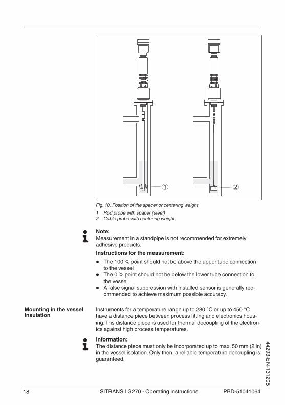
Standpipes or bypass tubes are normally metal tubes with a diameter of30…200mm(1.18…7.87in).Inmeasurementtechnology,sucha tube corresponds to a coax probe. It does not matter if the stand-pipe is perforated or slotted for better mixing. Lateral inlets in bypass tubesalsodonotinfluencethemeasurement.Measuring probes can be mounted in bypass tubes up to DN 200.For bypass tubes, select the probe length such that the blocking distance(deadband)oftheprobeisaboveorbelowthelateralfillingopenings. You can thus measure the complete range of the medium in the bypass tube. When designing the bypass tube, keep the blocking distance of the probe in mind and select the length above the upper lateralfillingopeningaccordingly.Microwaves can penetrate many plastics. For process technical rea-sons, plastic standpipes are problematic. If durability is no problem, then we recommend the use of metal standpipes.When the SITRANS LG270 is used in standpipes or bypass tubes, contact with the tube wall must be avoided. We recommend for this purpose a cable probe with centering weight.With rod probes, a spacer is generally not required. However, if there is a risk of the rod probe being pressed against the tube wall by in-flowingmedium,youshouldmountaspacerattheprobeendtoavoidcontact with the tube wall. In the case of cable probes, the cable can be strained.Keep in mind that buildup can form on the spacers. Strong buildup caninfluencethemeasurement.
Pressure
Standpipes or bypass tubes
18 PBD-51041064SITRANS LG270 - Operating Instructions
44293-EN-131205
1 2
Fig. 10: Position of the spacer or centering weight1 Rod probe with spacer (steel)2 Cable probe with centering weight
Note:Measurement in a standpipe is not recommended for extremely adhesive products.Instructions for the measurement:
• The 100 % point should not be above the upper tube connection to the vessel
• The 0 % point should not be below the lower tube connection to the vessel
• A false signal suppression with installed sensor is generally rec-ommended to achieve maximum possible accuracy.
Instruments for a temperature range up to 280 °C or up to 450 °C haveadistancepiecebetweenprocessfittingandelectronicshous-ing. Ths distance piece is used for thermal decoupling of the electron-ics against high process temperatures.
Information:Thedistancepiecemustonlybeincorporateduptomax.50mm(2in)in the vessel isolation. Only then, a reliable temperature decoupling is guaranteed.
Mounting in the vessel insulation

19PBD-51041064 SITRANS LG270 - Operating Instructions
4429
3-EN
-131
205
1
2
Fig. 11: Mounting the instrument on insulated vessels.1 Temperature insulation2 Ambient temperature on the housing
If there is a risk of the cable probe touching the vessel wall during operation due to product movements or agitators, etc., the measuring probeshouldbesecurelyfixed.Thereisaninsidethread(M8)inthegravityweight,e.g.foraneye-bolt(optional).Make sure that the probe cable is not completely taut. Avoid tensile loads on the cable.Avoidundefinedvesselconnections,i.e.theconnectionmustbeeithergroundedreliablyorisolatedreliably.Anyundefinedchangeofthis requirement can lead to measurement errors.If there is a danger of the rod probe touching the vessel wall, then the probe must be fastened at the bottom end.
Fasten

20 PBD-51041064SITRANS LG270 - Operating Instructions
44293-EN-131205
1
2
1
2
Fig. 12: Fasten the probe1 Measuring probe2 Retaining sleeve
Incaseofdifficultinstallationconditions,theprobecanbealsomounted laterally. For this purpose, adapt the rod with rod extensions or bow-shaped segments.Let the probe length determine automatically by the instrument to compensate the resulting running time changes.The determine probe length can deviate from the actual probe length when using bow-shaped segments.If installations such as struts, ladders, etc. exist on the vessel wall, then the probe should have a distance to the vessel wall of at least 300mm(11.81in).Youcanfindfurtherinformationinthesupplementaryinstructionsofthe rod extension.
Incaseofdifficultinstallationconditions,forexampleinasocket,theprobe can be adapted respectively with a rod extension.Let the probe length determine automatically by the instrument to compensate the resulting running time changes.Youcanfindfurtherinformationinthesupplementaryinstructionsofthe rod extension.
Vapours, superimposed gases, high pressures and temperature dif-ferences can change the spreading speed of radar impulses.There are two possibilities to correct these deviations.
Corrective value in the process control systemInthetechnicaldataunder"Influenceofsuperimposedgasandpres-sureonaccuracy"youcanfindatablewithdeviationvaluesinsometypical gases or in steam.
Lateral installation
Rod extension
Steam boiler applications

21PBD-51041064 SITRANS LG270 - Operating Instructions
4429
3-EN
-131
205
Inthecontrolsystem(DCS)youcancorrectthemeasurementresultsof the SITRANS LG270 with these values.The prerequisite is constant temperature and pressure in the vessel.
Automatic correction via the reference distanceThe SITRANS LG270 can be equipped optionally with a running time correction via reference distance. The probe can carry out an auto-matic running time correction with it.Thereferencepointmusthencenotbeoverfilled.Theupperdeadbandishence450mm(17.7in).
2
6
3
4
5
1
2
6
5
4
3
1
7 7
Fig. 13: Measuring ranges - SITRANS LG270 with steam compensation1 Reference plane2 Probe length L3 Measuring range4 Upper dead band5 Lower dead band6 Additional upper dead band by steam compensation7 Reference measurement distance to steam compensation

22 PBD-51041064SITRANS LG270 - Operating Instructions
44293-EN-131205
5 Connecting to power supply
5.1 Preparing the connectionAlways keep in mind the following safety instructions:
• Connect only in the complete absence of line voltage• If overvoltage surges are expected, overvoltage arresters should
be installed
In this case, the instrument is designed in protection class II. To main-tain this protection class, it is absolutely necessary that the ground conductor be connected to the internal ground terminal. Take note of the general installation regulations.Supply voltage and current signal are carried on separate connection cables if reliable separation is required. The supply voltage range can differdependingontheinstrumentversion.Thedataforpowersupplyarespecifiedinchapter"Technical data".
In this case, the instrument is designed in protection class II. Gener-allyconnecttheinstrumenttovesselground(potentialequalization)or with plastic vessels to the next ground potential. For this purpose, a ground terminal is located laterally on the instrument housing.
An approved, three-wire installation cable with PE conductor is required for voltage supply with mains voltage.The 4 … 20 mA current output is connected with standard two-wire cable without screen. If electromagnetic interference is expected which is above the test values of EN 61326-1 for industrial areas, screened cable should be used.For instruments with housing and cable gland, use cable with round cross-section.Toensurethesealeffectofthecablegland(IPprotec-tionrating),youhavetocheckforwhichcableouterdiameterthecable gland is suitable.
• 5…9mm(0.20…0.35in)• 6…12mm(0.24…0.47in)• 10…14mm(0.40…0.55in)Useacableglandfittingthecablediameter.
With plastic housing, the NPT cable gland or the Conduit steel tube must be screwed without grease into the threaded insert.Max. torque for all housings see chapter "Technical data".
If screened cable is required, we recommend connecting the cable screen on both ends to ground potential. In the sensor, the screen must be connected directly to the internal ground terminal. The ground terminal on the outside of the housing must be connected to thegroundpotential(lowimpedance).With Ex systems it must be ensured that the grounding corresponds to the installation regulations.
Safety instructions
Voltage supply via mains voltage
Voltage supply via low voltage
Connection cable
Cable gland ½ NPT
Cable screening and grounding
23PBD-51041064 SITRANS LG270 - Operating Instructions
4429
3-EN
-131
205
InelectroplatingandCCPsystems(cathodiccorrosionprotection)itmustbetakenintoaccountthatsignificantpotentialdifferencesexist.This can lead to unacceptably high shield currents if the cable shield is grounded at both ends.
Information:Themetallicpartsoftheinstrument(processfitting,transmitter,con-centrictube,etc.)areconductivelyconnectedwiththeinnerandouterground terminal on the housing. This connection exists either directly via connecting metallic parts or, in case of instruments with external electronics, via the screen of the special connection cable.Youcanfindspecificationsonthepotentialconnectionsinsidetheinstrument in chapter "Technical data".
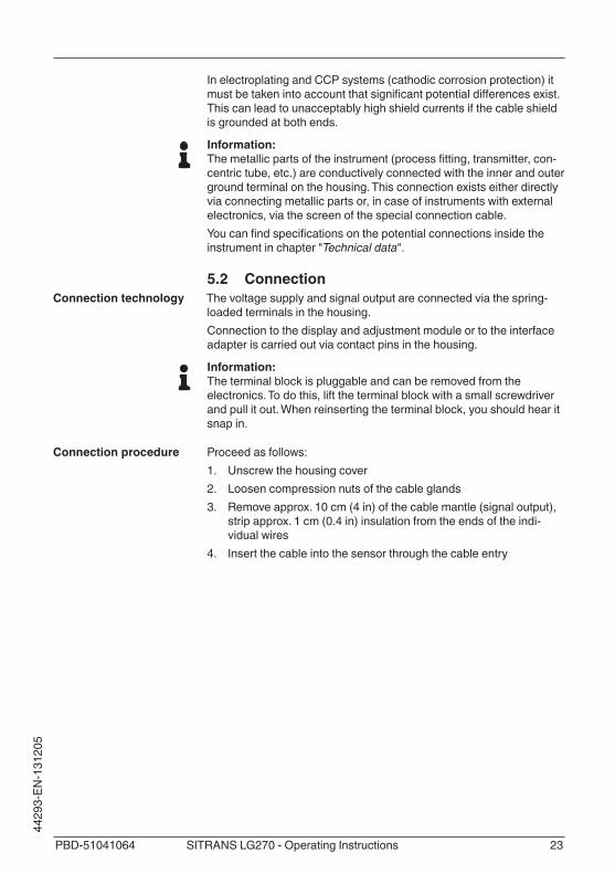
5.2 ConnectionThe voltage supply and signal output are connected via the spring-loaded terminals in the housing.Connection to the display and adjustment module or to the interface adapter is carried out via contact pins in the housing.
Information:The terminal block is pluggable and can be removed from the electronics. To do this, lift the terminal block with a small screwdriver and pull it out. When reinserting the terminal block, you should hear it snap in.
Proceed as follows:1. Unscrew the housing cover2. Loosen compression nuts of the cable glands3. Removeapprox.10cm(4in)ofthecablemantle(signaloutput),
stripapprox.1cm(0.4in)insulationfromtheendsoftheindi-vidual wires
4. Insert the cable into the sensor through the cable entry
Connection technology
Connection procedure

24 PBD-51041064SITRANS LG270 - Operating Instructions
44293-EN-131205
Fig. 14: Connection steps 5 and 6
5. Insert the wire ends into the terminals according to the wiring plan
Information:Solidcoresaswellasflexiblecoreswithwireendsleevesareinsert-eddirectlyintotheterminalopenings.Incaseofflexiblecoreswithoutend sleeves, press the terminal from above with a small screwdriver, the terminal opening is then free. When the screwdriver is released, the terminal closes again.6. Check the hold of the wires in the terminals by lightly pulling on
them7. Connect the screen to the internal ground terminal, connect the
outer ground terminal to potential equalisation in case of power supply via low voltage
8. Connect the lead cable for power supply in the same way accord-ing to the wiring plan, in addition connect the ground conductor to the inner ground terminal when powered with mains voltage.
9. Tighten the compression nut of the cable glands. The seal ring must completely encircle the cables
10. Screw the housing cover back onTheelectricalconnectionisfinished.
Information:The terminal blocks are pluggable and can be removed from the housing insert. To do this, lift the terminal block with a small screwdriv-er and pull it out. When inserting the terminal block again, you should hear it snap in.
5.3 Wiring plan, double chamber housingThe following illustrations apply to the non-Ex as well as to the Ex-d-ia version.

25PBD-51041064 SITRANS LG270 - Operating Instructions
4429
3-EN
-131
205
5 6 7 8
4...20mA
2
1 2+( ) (-)
31
Fig. 15: Electronics compartment, double chamber housing1 Internal connection to the connection compartment2 For display and adjustment module or interface adapter3 Internal connection to the plug connector for external display and adjust-
ment unit (optional)
Information:The connection of an external display and adjustment unit is not pos-sible with this double chamber housing.
power supply
4...20mA
activ
e
pass
ive
com
mon
IS G
ND
51
/L/N
PE
2+( ) (-) 6 7 8
Fig. 16: Connection compartment with double chamber housing with mains voltage
Terminal Function Polarity
1 Voltage supply +/L
2 Voltage supply -/N
5 4…20mAoutput(active) +
6 4…20mAoutput(passive) +
7 Mass - output -
8 Function ground with installa-tion according to CSA
Electronics compartment
Connection compartment with mains voltage

26 PBD-51041064SITRANS LG270 - Operating Instructions
44293-EN-131205
power supply
4...20mA
activ
e
pass
ive
com
mon
IS G
ND
51
/L/N
2+( ) (-) 6 7 8
Fig. 17: Connection compartment with double chamber housing with low volt-age
Terminal Function Polarity
1 Voltage supply +/L
2 Voltage supply -/N
5 4…20mAoutput(active) +
6 4…20mAoutput(passive) +
7 Mass - output -
8 Function ground with installa-tion according to CSA
5.4 Supplementary electronicsYou can use the supplementary electronics - second current output to provided a second measured value.Both current outputs are passive and need a power supply.
1 2+( ) (-)
I4...20mA
I I4...20mA
7 8+( ) (-)
31 2
Fig. 18: Connection compartment double chamber housing, supplementary electronics - second current output1 First current output (I) - Voltage supply and signal output (HART)2 Second current output (II) - Voltage supply and signal output (without HART)3 Ground terminal for connection of the cable screen
5.5 Switch-on phaseAfter connecting the instrument to power supply or after a voltage recurrence, the instrument carries out a self-check for approx. 30 s:
Connection compartment with low voltage
Supplementary electron-ics - Second current output

27PBD-51041064 SITRANS LG270 - Operating Instructions
4429
3-EN
-131
205
• Internal check of the electronics• Indication of the instrument type, hardware and software version,
measurement loop name on the display or PC• Indication of the status message "F 105 Determine measured
value" on the display or PC• The output signal jumps to the set fault current
As soon as a plausible measured value is found, the corresponding current is outputted to the signal cable. The value corresponds to the actual level as well as the settings already carried out, e.g. factory setting.

28 PBD-51041064SITRANS LG270 - Operating Instructions
44293-EN-131205
6 Set up with the display and adjustment module
6.1 Insert display and adjustment moduleThe display and adjustment module can be inserted into the sensor and removed any time. Four positions displaced by 90° can be se-lected. It is not necessary to interrupt the power supply.Proceed as follows:1. Unscrew the housing cover2. Place the display and adjustment module in the requested posi-
tion onto the electronics and turn to the right until it snaps in3. Screw housing cover with inspection window tightly back onRemoval is carried out in reverse order.The display and adjustment module is powered by the sensor, an ad-ditional connection is not necessary.
Fig. 19: Installing the display and adjustment module in the electronics compart-ment of the single chamber housing
29PBD-51041064 SITRANS LG270 - Operating Instructions
4429
3-EN
-131
205
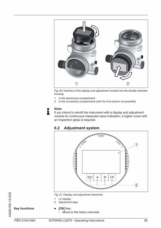
1 2
Fig. 20: Insertion of the display and adjustment module into the double chamber housing1 In the electronics compartment2 In the connection compartment (with Ex-d-ia version not possible)
Note:Ifyouintendtoretrofittheinstrumentwithadisplayandadjustmentmodule for continuous measured value indication, a higher cover with an inspection glass is required.
6.2 Adjustment system
1
2
Fig. 21: Display and adjustment elements1 LC display2 Adjustment keys
• [OK] key: – Move to the menu overview
Key functions

30 PBD-51041064SITRANS LG270 - Operating Instructions
44293-EN-131205
– Confirmselectedmenu – Edit parameter – Save value
• [->] key: – Presentation, change measured value – Select list entry – Select editing position
• [+] key: – Change value of the parameter
• [ESC] key: – Interrupt input – Jump to next higher menu
The sensor is adjusted via the four keys of the display and adjust-ment module. The LC display indicates the individual menu items. The functions of the individual keys are shown in the above illustration. Approx. 10 minutes after the last pressing of a key, an automatic reset tomeasuredvalueindicationistriggered.Anyvaluesnotconfirmedwith [OK] will not be saved.
After switching on, the SITRANS LG270 carries out a short self-test where the device software is checked.The output signal transmits a fault signal during the switch-on phase.The following information is displayed on the display and adjustment module during the startup procedure:
• Instrument type• Device name• Softwareversion(SW-Ver)• Hardwareversion(HW-Ver)
With the [->]keyyoucanmovebetweenthreedifferentindicationmodes.Inthefirstview,theselectedmeasuredvalueisdisplayedinlargedigits.In the second view, the selected measured value and a correspond-ing bar graph presentation are displayed.In the third view, the selected measured value as well as a second selectable value, e.g. the temperature, are displayed.
6.3 Parameter adjustment - Quick setupTo quickly and easily adapt the sensor to the application, select the menu item "Quick setup" in the start graphic on the display and adjustment module.
Adjustment system
Switch-on phase
Measured value indica-tion
Quick setup

31PBD-51041064 SITRANS LG270 - Operating Instructions
4429
3-EN
-131
205
Youcanfind"Extendedadjustment"inthenextsub-chapter.
Measurement loop nameInthefirstmenuitemyoucanassignasuitablemeasurementloopname. You can enter a name with max. 19 characters.
Type of mediumIn the next menu item you can see which type of medium the instru-ment is suitable for. If your instrument is only suitable for a certain medium, this menu item is not visible.
ApplicationIn this menu item, you can select the application. You can choose between level measurement and interface measurement. You can also choose between measurement in a vessel or in a bypass or standpipe.
Medium - dielectric constantInthismenuitem,youcandefinethetypeofmedium(product).
Max. adjustmentIn this menu item, you can enter the max. adjustment for the level.Entertheappropriatedistancevalueinm(correspondingtothepercentagevalue)forthefullvessel.Thedistancereferstothesensorreferenceplane(sealsurfaceoftheprocessfitting).Keepinmindthatthe max. level must lie below the dead band.
Min. adjustmentIn this menu item, you can enter the min. adjustment for the level.Enterthesuitabledistancevalueinmfortheemptyvessel(e.g.distancefromtheflangetotheprobeend)correspondingtotheper-centagevalue.Thedistancereferstothesensorreferenceplane(sealsurfaceoftheprocessfitting).
Dielectric constant - upper mediumInthismenuitem,youcandefinethetypeofmedium(product).
Max. adjustmentIn this menu item, you can enter the max. adjustment for the level.Entertheappropriatedistancevalueinm(correspondingtothepercentagevalue)forthefullvessel.Thedistancereferstothesensor
General information
Level measurement
Interface measurement

32 PBD-51041064SITRANS LG270 - Operating Instructions
44293-EN-131205
referenceplane(sealsurfaceoftheprocessfitting).Keepinmindthatthe max. level must lie below the dead band.
Min. adjustmentIn this menu item, you can enter the min. adjustment for the level.Enterthesuitabledistancevalueinmfortheemptyvessel(e.g.distancefromtheflangetotheprobeend)correspondingtotheper-centagevalue.Thedistancereferstothesensorreferenceplane(sealsurfaceoftheprocessfitting).
Max. adjustment - InterfaceCarry out the max. adjustment for the interface.To do this, enter the percentage value and the suitable distance value in m for the full vessel.
Min. adjustment - InterfaceCarry out the min. adjustment for the interface.To do this, enter the percentage value and the suitable distance value in m for the empty vessel.
LinearizationAlinearizationisnecessaryforallvesselsinwhichthevesselvolumedoesnotincreaselinearlywiththelevel-e.g.ahorizontalcylindri-cal or spherical tank, when the indication or output of the volume is required.Correspondinglinearizationcurvesarepreprogrammedfor these vessels. They represent the correlation between the level percentage and vessel volume.Thelinearizationappliesforthemeasuredvalueindicationandthecurrent output. By activating the suitable curve, the percentage vessel volume is displayed correctly.
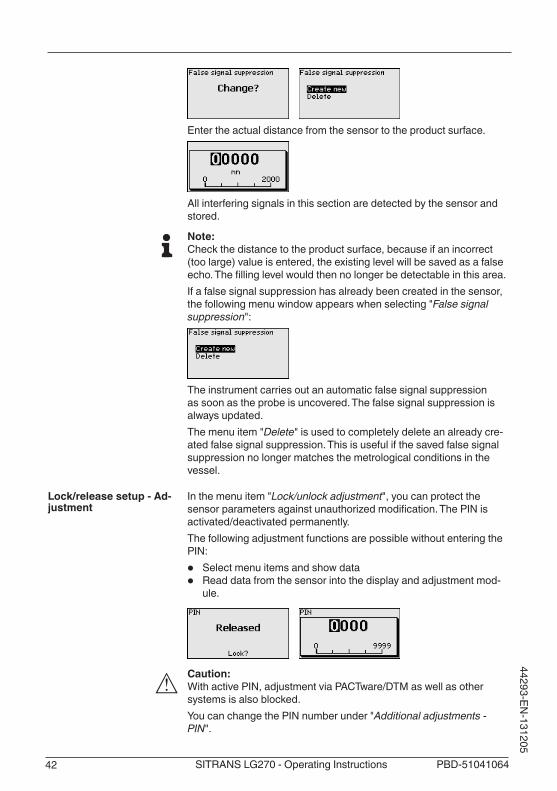
False signal suppressionHighsocketsandinternalvesselinstallationscauseinterferingreflec-tionsandcaninfluencethemeasurement.A false signal suppression detects, marks and saves these false signals so that they are no longer taken into account for the level and interface measurement. We generally recommend carrying out a false signal suppression to achieve the best possible accuracy. This should be done with the lowest possible level so that all potential interfering reflectionscanbedetected.Enter the actual distance from the sensor to the product surface.All interfering signals in this section are detected by the sensor and stored.
Linearization

33PBD-51041064 SITRANS LG270 - Operating Instructions
4429
3-EN
-131
205
The instrument carries out an automatic false signal suppression as soon as the probe is uncovered. The false signal suppression is always updated.
6.4 Parameter adjustment - Extended adjustmentFor technically demanding measuring points, you can carry out extended settings in "Extended adjustment".
Themainmenuisdividedintofivesectionswiththefollowingfunc-tions:
Setup: Settings, e.g. measurement loop name, medium, vessel, adjustment, signal output, device unit, false signal suppression, linearizationcurveDisplay: Settings, e.g., for language, measured value display, lightingDiagnosis: Information, e.g. on instrument status, pointer, measure-ment reliability, simulation, echo curveAdditional adjustments: Reset, date/time, reset, copy functionInfo: Instrument name, hardware and software version, date of manu-facture, instrument features
Note:For optimum adjustment of the measuring point, the individual sub-menu items in the main menu item "Setup" should be selected one after the other and provided with the correct parameters. If possible, go through the items in the given sequence.The procedure is described below.The following submenu points are available:
The submenu points described below.
Here you can assign a suitable measurement loop name. Push the "OK" key to start the processing. With the "+" key you change the sign and with the "->"keyyoujumptothenextposition.
Main menu
Setup - Measurement loop name

34 PBD-51041064SITRANS LG270 - Operating Instructions
44293-EN-131205
You can enter names with max. 19 characters. The character set comprises:
• Capital letters from A … Z• Numbers from 0 … 9• Special characters + - / _ blanks
In this menu item you select the distance unit and the temperature unit.
With the distance units you can choose between m, mm and ft and with the temperature units betwenn °C, °F and K.
In this menu item you can enter the probe length or have the length determined automatically by the sensor system.When choosing "Yes", then the probe length will be determined automatically. When choosing "No", you can enter the probe length manually.
In this menu item you can select which type of medium you want to measure. You can choose between liquid or bulk solid.
In this menu item, you can select the application. You can choose between level measurement and interface measurement. You can also choose between measurement in a vessel or in a bypass or standpipe.
Note:Theselectionoftheapplicationhasaconsiderableinfluenceonallother menu items. Keep in mind that as you continue with the param-eter adjustment, individual menu items are only optionally available.You have the option of choosing the demonstration mode. This mode is only suitable for test and demonstration purposes. In this mode, the sensor ignores the parameters of the application and reacts immedi-ately to each change.
Setup - Units
Setup - Probe length
Setup - Type of medium
Setup - Application - Ap-plication

35PBD-51041064 SITRANS LG270 - Operating Instructions
4429
3-EN
-131
205
Inthismenuitem,youcandefinethetypeofmedium(product).This menu item is only available if you have selected level measure-ment under the menu item "Application".
You can choose between the following medium types:
Dielectric con-stant
Type of medium Examples
>10 Water-based liq-uids
Acids, alcalis, water
3 … 10 Chemical mix-tures
Chlorobenzene,nitrolacquer,aniline,isocyanate, chloroform
< 3 Hydrocarbons Solvents, oils, liquid gas
This menu item is only available, if you have chosen interface meas-urement under the menu item "Application". In this menu item you can enter if there is a superimposed gas phase in your application.Only set the function to "Yes", if the gas phase is permanently pre-sent.
This menu item is only available if you have selected interface meas-urement under the menu item "Application". In this menu item you can choose the type of medium of the upper medium.
You can enter the dielectric constant of the upper medium directly or have the value determined by the instrument. To do this you have to enter the measured or known distance to the interface.
In this menu item you can enter the max. adjustment for the level. With interface measurement this is the maximum total level.
Setup - Application - Me-dium, dielectric constant
Setup - Application - Gas phase
Setup - Application - Di-electric constant
Setup - Max. adjustment Level

36 PBD-51041064SITRANS LG270 - Operating Instructions
44293-EN-131205
Adjust the requested percentage value with [+] and store with [OK].
Entertheappropriatedistancevalueinm(correspondingtothepercentagevalue)forthefullvessel.Thedistancereferstothesensorreferenceplane(sealsurfaceoftheprocessfitting).Keepinmindthatthe max. level must lie below the dead band.
In this menu item you can enter the min. adjustment for the level. With interface measurement this is the minimum total level.
Adjust the requested percentage value with [+] and store with [OK].
Enterthesuitabledistancevalueinmfortheemptyvessel(e.g.distancefromtheflangetotheprobeend)correspondingtotheper-centagevalue.Thedistancereferstothesensorreferenceplane(sealsurfaceoftheprocessfitting).
This menu item is only available if you have selected interface meas-urement under the menu item "Application".
You can accept the adjustment of the level measurement also for the interface measurement. If you select "Yes", the current setting will be displayed.
Setup - Min. adjustment Level
Setup - Max. adjustment - Interface

37PBD-51041064 SITRANS LG270 - Operating Instructions
4429
3-EN
-131
205
If you have selected "No", you can enter the adjustment for the inter-face separately. Enter the requested percentage value.
For the full vessel, enter the distance value in m matching the per-centage value.
This menu item is only available if you have selected interface meas-urement under the menu item "Application". If you have selected "Yes" inthepreviousmenuitem(acceptadjustmentofthelevelmeasure-ment),thecurrentsettingwillbedisplayed.
If you have selected "No", you can enter the adjustment for the inter-face measurement separately.
Enter the respective distance value in m for the empty vessel cor-responding to the percentage value.
Todampprocess-dependentmeasuredvaluefluctuations,setanintegration time of 0 … 999 s in this menu item.If you have selected interface measurement under the menu item "Application", you can adjust the damping for the level and the inter-face separately.
The default setting is a damping of 0 s.
Alinearizationisnecessaryforallvesselsinwhichthevesselvolumedoesnotincreaselinearlywiththelevel-e.g.ahorizontalcylindri-cal or spherical tank, when the indication or output of the volume is required.Correspondinglinearizationcurvesarepreprogrammedfor these vessels. They represent the correlation between the level percentage and vessel volume.Thelinearizationappliestothemeasuredvalueindicationandthecurrent output. By activating the appropriate curve, the volume per-
Setup - Min. adjustment - Interface
Setup - Damping
Setup - Linearization

38 PBD-51041064SITRANS LG270 - Operating Instructions
44293-EN-131205
centage of the vessel is displayed correctly. If the volume should not be displayed in percent but e.g. in l or kg, a scaling can be also set in the menu item "Display".
Warning:Ifalinearizationcurveisselected,themeasuringsignalisnolongernecessarilylineartothefillingheight.Thismustbeconsideredbytheuser especially when adjusting the switching point on the limit signal transmitter.In the following, you have to enter the values for your vessel, for example the vessel height and the socket correction.For non-linear vessel forms, enter the vessel height und the socket correction.For the vessel height, you have to enter the total height of the vessel.For the socket correction you have to enter the height of the socket above the upper edge of the vessel. If the socket is lower than the up-per edge of the vessel, this value can also be negative.
+ h
D
- h
Fig. 22: Vessel height und socket correction valueD Vessel height+h Positive socket correction value-h Negative socket correction value

39PBD-51041064 SITRANS LG270 - Operating Instructions
4429
3-EN
-131
205
Since scaling is very extensive, scaling of the level value was divided into two menu items.
In menu item "Level 1"youdefinethescalingvariableandthescalingunit for the level value on the display, e.g. volume in l.
Since scaling is very extensive, scaling of the level value was divided into two menu items.
In menu item "Level 2"youdefinethescalingformatonthedisplayand the scaling of the measured level value for 0 % and 100 %.
Since scaling is very extensive, scaling of the interface value was divided into two menu items.
In menu item "Interface 1"youdefinethescalingsizeandthescalingunit for the interface value on the display, e.g. volume in l.You can accept the scaling of the level measurement also for the interface measurement. If you select "Yes", the current setting is displayed.
If you have selected "No", you can enter the scaling for the interface separately.
Setup - Scaling Level
Setup - Scaling Level 1
Setup - Scaling Level 2
Setup - Scaling Interface
Setup - Scaling Interface (1)

40 PBD-51041064SITRANS LG270 - Operating Instructions
44293-EN-131205
In menu item "Interface (2)"youdefinethescalingformatonthedisplay and the scaling of the interface measured value for 0 % and 100 %.
In menu item"Current output, size" you determine which measured value the current output refers to.
In menu item "Current output, adjustment" you can assign a respec-tive measured value to the current output.
In the menu item "Current output mode" you determine the output characteristics and reaction of the current output in case of failure.
The default setting is output characteristics 4 … 20 mA, failure mode < 3.6 mA.
Setup - Scaling Interface (2)
Setup - Current output Size
Setup - Current output, adjustment
Setup - Current output mode

41PBD-51041064 SITRANS LG270 - Operating Instructions
4429
3-EN
-131
205
In the menu item "Current output Min./Max.", you determine the reac-tion of the current output during operation.
The default setting is min. current 3.8 mA and max. current 20.5 mA.
Since the HART variables are very extensive, the indication was divided into two menu items.In the menu "HART variables 1"youcanhavethefirstHARTvaluePV(primaryvalue)andthesecondHARTvalueSV(secondaryvalue)ofthe sensor displayed.The values cannot be changed in the display and adjustment module. To change these values, you have to use the adjustment software PACTware.
In the menu "HART variables 2" you can have the third HART value TV(thirdvalue)andthefourthHARTvalueQV(quartervalue)ofthesensor displayed.The values cannot be changed in the display and adjustment module. To change these values, you have to use the adjustment software PACTware.
Thefollowingcircumstancescauseinterferingreflectionsandcaninfluencethemeasurement:
• High sockets• Vessel installations such as struts
Note:A false signal suppression detects, marks and saves these false signals so that they are no longer taken into account for the level and interface measurement. We generally recommend carrying out a false signal suppression to achieve the best possible accuracy. This should be done with the lowest possible level so that all potential interfering reflectionscanbedetected.Proceed as follows:
Setup - Current output Min./Max.
Setup - HART variables (1)
Setup - HART variables (2)
Setup - False signal sup-pression
42 PBD-51041064SITRANS LG270 - Operating Instructions
44293-EN-131205
Enter the actual distance from the sensor to the product surface.
All interfering signals in this section are detected by the sensor and stored.
Note:Check the distance to the product surface, because if an incorrect (toolarge)valueisentered,theexistinglevelwillbesavedasafalseecho.Thefillinglevelwouldthennolongerbedetectableinthisarea.If a false signal suppression has already been created in the sensor, the following menu window appears when selecting "False signal suppression":
The instrument carries out an automatic false signal suppression as soon as the probe is uncovered. The false signal suppression is always updated.The menu item "Delete" is used to completely delete an already cre-ated false signal suppression. This is useful if the saved false signal suppression no longer matches the metrological conditions in the vessel.
In the menu item "Lock/unlock adjustment", you can protect the sensorparametersagainstunauthorizedmodification.ThePINisactivated/deactivated permanently.The following adjustment functions are possible without entering the PIN:
• Select menu items and show data• Read data from the sensor into the display and adjustment mod-
ule.
Caution:With active PIN, adjustment via PACTware/DTM as well as other systems is also blocked.You can change the PIN number under "Additional adjustments - PIN".
Lock/release setup - Ad-justment

43PBD-51041064 SITRANS LG270 - Operating Instructions
4429
3-EN
-131
205
In the main menu point "Display", the individual submenu points should be selected subsequently and provided with the correct parameters to ensure the optimum adjustment of the display options. The procedure is described in the following.The following submenu points are available:
The submenu points described below.
This menu item enables the setting of the requested national lan-guage.
In the delivery status, the sensor is set to the ordered national lan-guage.
Inthismenuitem,youdefinetheindicationofthemeasuredvalueonthedisplay.Youcandisplaytwodifferentmeasuredvalues.Inthismenuitem,youdefinemeasuredvalue1.
The default setting for the displayed value 1 is "Filling height Level".
Inthismenuitem,youdefinetheindicationofthemeasuredvalueonthedisplay.Youcandisplaytwodifferentmeasuredvalues.Inthismenuitem,youdefinemeasuredvalue2.
The default setting for the displayed value 2 is the electronics tem-perature.
The optionally integrated background lighting can be adjusted via the adjustment menu. The function depends on the height of the supply voltage, see "Technical data".
Thelightingisswitchedoffindeliverystatus.
Display
Display - Menu language
Display - Displayed value 1
Display - Displayed value 2
Display - Backlight

44 PBD-51041064SITRANS LG270 - Operating Instructions
44293-EN-131205
In this menu item, the device status is displayed.
The respective min. and max. measured value is saved in the sen-sor. The two values are displayed in the menu item "Peak values, distance".If you have selected interface measurement under the menu item "Setup - Application", the peak values of the interface measurement are displayed in addition to the peak values of the level measurement.
In another window you can carry out a reset of the two peak values separately.
The respective min. and max. measured values are saved in the sensor. The two values are displayed in the menu item "Peak values, measurement certainty".Themeasurementcanbeinfluencedbytheprocessconditions.Inthis menu item, the measurement certainty of the level measurement is displayed as percentage value. The higher the value, the more reli-ablethemeasurement.Values>90%indicatereliablemeasurement.If you have selected interface measurement under the menu item "Setup - Application", the peak values of the interface measurement are displayed in addition to the peak values of the level measurement.
In another window you can carry out a reset of the two peak values separately.
The respective min. and max. measured values are saved in the sensor. The values are displayed in the menu item "Peak values Ad-ditional".This menu item displays the peak values of the electronics tempera-ture as well as the dielectric constant.
Diagnostics - Device status
Diagnostics - Peak values Distance
Diagnostics - Peak values Measurement certainty
Diagnostics - Peak values Additional

45PBD-51041064 SITRANS LG270 - Operating Instructions
4429
3-EN
-131
205
In another window you can carry out a reset of the two peak values separately.
The menu item "Echo curve" shows the signal strength of the echoes over the measuring range in V. The signal strength enables an evalua-tion of the quality of the measurement.
Withthefollowingfunctionsyoucanzoompartsectionsoftheechocurve.
• "X-Zoom":Zoomfunctionforthemeas.distance• "Y-Zoom":1,2,5and10xsignalmagnificationin"V"• "Unzoom":Resetthepresentationtothenominalmeasuringrange
withsinglemagnification
In this menu item you can simulate measured values via the current output. This allows the signal path to be tested, e.g. through down-stream indicating instruments or the input card of the control system.
Selecttherequestedsimulationsizeandadjusttherequestedvalue.
Caution:During simulation, the simulated value is outputted as 4 … 20 mA cur-rent value and digital HART signal.Push the [ESC] key to deactivate the simulation.
Diagnostics - Echo curve
Diagnosis - Simulation

46 PBD-51041064SITRANS LG270 - Operating Instructions
44293-EN-131205
Information:The simulation is terminated automatically 60 minutes after the last key has been pressed.
With the menu item "Setup" the echo curve it is possible to save at the time of setup. This is generally recommended; for using the Asset Management functions it is necessary. If possible, the curve should be saved with a low level in the vessel.With this, you can detect signal changes over the operating time. With the adjustment software PACTware and the PC, the high-resolution echo curve can be displayed and used to compare the echo curve of the setup with the actual echo curve.
The function "Echo curve memory" enables storing echo curves of the measurement.Under the sub-menu item "Echo curve memory" you can store the current echo curve.Parameter settings for recording the echo curve and the settings of the echo curve itself can be carried out in the adjustment software PACTware.With the adjustment software PACTware and the PC the high-reso-lution echo curve can be displayed and used later on to assess the quality of the measurement.
Enteringa4-digitPINprotectsthesensordataagainstunauthorizedaccessandunintentionalmodification.Inthismenuitem,thePINisdisplayed or edited and changed. However, this menu item is only available if adjustment is enabled in the menu "Lock/Release setup/adjustment".
In delivery status, the PIN is "0000".
In this menu item, the internal clock of the sensor is adjusted.
Diagnostics - Echo curve memory
Additional settings - PIN
Additional adjustments - Date Time
47PBD-51041064 SITRANS LG270 - Operating Instructions
4429
3-EN
-131
205
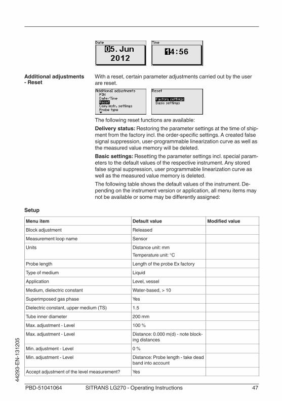
With a reset, certain parameter adjustments carried out by the user are reset.
The following reset functions are available:Delivery status: Restoring the parameter settings at the time of ship-mentfromthefactoryincl.theorder-specificsettings.Acreatedfalsesignalsuppression,user-programmablelinearizationcurveaswellasthe measured value memory will be deleted.Basic settings: Resetting the parameter settings incl. special param-eters to the default values of the respective instrument. Any stored falsesignalsuppression,userprogrammablelinearizationcurveaswell as the measured value memory is deleted.The following table shows the default values of the instrument. De-pending on the instrument version or application, all menu items may notbeavailableorsomemaybedifferentlyassigned:
Setup
Menu item Default value Modifiedvalue
Block adjustment Released
Measurement loop name Sensor
Units Distance unit: mmTemperature unit: °C
Probe length Length of the probe Ex factory
Type of medium Liquid
Application Level, vessel
Medium, dielectric constant Water-based,>10
Superimposed gas phase Yes
Dielectricconstant,uppermedium(TS) 1.5
Tube inner diameter 200 mm
Max. adjustment - Level 100 %
Max. adjustment - Level Distance:0.000m(d)-noteblock-ing distances
Min. adjustment - Level 0 %
Min. adjustment - Level Distance: Probe length - take dead band into account
Accept adjustment of the level measurement? Yes
Additional adjustments - Reset

48 PBD-51041064SITRANS LG270 - Operating Instructions
44293-EN-131205
Menu item Default value Modifiedvalue
Max. adjustment - Interface 100 %
Max. adjustment - Interface Distance:0.000m(d)-noteblock-ing distances
Min. adjustment - Interface 0 %
Min. adjustment - Interface Distance: Probe length - take dead band into account
Integration time - Level 0.0 s
Integration time - Interface 0.0 s
Linearizationtype Linear
Linearization-Socketcorrection 0 mm
Linearization-Vesselheight Probe length
Scalingsize-Level Volume in l
Scaling unit - Level Litres
Scaling format - Level Without decimal positions
Scaling level - 100 % correspond to 100
Scaling level - 0 % correspond to 0
Accept scaling of the level measurement Yes
Scaling variable - Interface Volume
Scaling unit - Interface Litres
Scaling format - Interface Without decimal positions
Scaling interface - 100 % correspond to 100
Scaling interface - 0 % correspond to 0
Current output, output variableFirstHARTvariable(PV)
Lin. percent - Level
Current output - Output characteristics 0 … 100 % correspond to 4 … 20 mA
Current output - Reaction in case of failure ≤3.6mA
Current output - Min. 3.8 mA
Current output - Max. 20.5 mA
Current output 2 - Output variableSecondHARTvariable(SV)
Distance - Level
Current output 2 - Output characteristics 0 … 100 % correspond to 4 … 20 mA
Current output 2 - Reaction in case of failure ≤3.6mA
Current output - Min. 3.8 mA
Current output - Max. 20.5 mA
ThirdHARTvariable(TV) Measurement certainty, level
FourthHARTvariable(QV) Electronics temperature

49PBD-51041064 SITRANS LG270 - Operating Instructions
4429
3-EN
-131
205
Display
Menu item Default value Modifiedvalue
Language Order-specific
Displayed value 1 Filling height Level
Displayed value 2 Electronics temperature
Backlight Switchedoff
Diagnostics
Menu item Default value Modifiedvalue
Status signals - Function control Switched on
Statussignals-Outofspecification Switchedoff
Status signals - Maintenance Switchedoff
Device memory - Echo curve memory Stopped
Device memory - Measured value memory Started
Device memory - Measured value memory - Measured values
Distance level, percentage value level, reliability level, electronics temperature
Device memory - Measured value memory - Re-cording in time interval
3 min.
Device memory - Measured value memory - Re-cordingwithmeasuredvaluedifference
15 %
Device memory - Measured value memory - Start with measured value
Not active
Device memory - Measured value memory - Stop with measured value
Not active
Device memory - Measured value memory - Stop recording when memory is full
Not active
Additional adjustments
Menu item Default value Modifiedvalue
PIN 0000
Date Actual date
Time Actual time
Time - Format 24 hours
Probe type Device-specific
The instrument settings are copied with this function. The following functions are available:
• Read from sensor: Read data from sensor and store into the display and adjustment module
• Write into sensor: Store data from the display and adjustment module back to the sensor
Additional adjustments - Copy instrument settings

50 PBD-51041064SITRANS LG270 - Operating Instructions
44293-EN-131205
The following data or settings for adjustment of the display and ad-justment module are saved:
• All data of the menu "Setup" and "Display"• In the menu "Additional adjustments" the items "Reset, Date/Time"• Special parameters
The copied data are permanently saved in an EEPROM memory in the display and adjustment module and remain there even in case of power failure. From there, they can be written into one or more sen-sors or kept as backup for a possible electronics exchange.
Note:Before the data are stored in the sensor, a check is carried out to determineifthedatafitthesensor.Ifthedatadonotfit,afaultsignalis triggered or the function is blocked. When data are being written into the sensor, the display shows which instrument type the data originate from and which TAG-no. this sensor had.
Inthismenuitemyoucanselectthetypeandsizeofyourprobefroma list of all possible probes. This is necessary to adapt the electronics optimally to the probe.
In this menu item you gain access to the protected area where you can enter special parameters. In exceptional cases, individual parameterscanbemodifiedinordertoadaptthesensortospecialrequirements.Change the settings of the special parameters only after having con-tactedourservicestaff.
ThesensorofferstheHARTmodes"Analogue current output" and "Fix current (4 mA)". In this menu item you determine the HART mode and enter the address with Multidrop mode.In the mode "Fixed current output" up to 63 sensors can be operated ononetwo-wirecable(Multidropoperation).Anaddressbetween0and 63 must be assigned to each sensor.If you select the function "Analogue current output" and also enter an address number, you can output a 4 … 20 mA signal in Multidrop mode.
Additional adjustments - Probe type
Additional adjustments - Special parameters
Additional adjustments - HART mode

51PBD-51041064 SITRANS LG270 - Operating Instructions
4429
3-EN
-131
205
With the mode "Fixed current (4 mA)"afixed4mAsignalisoutputtedindependently of the actual level.
The default setting is "Analogue current output" and the address 00.
In this menu, you read out the instrument name and the instrument serial number.
In this menu item, the hardware and software version of the sensor is displayed.
In this menu item, the date of factory calibration of the sensor as well as the date of the last change of sensor parameters are displayed via the display and adjustment module or via the PC.
In this menu item, the features of the sensor such as approval, pro-cessfitting,seal,measuringrange,electronics,housingandothersare displayed.
6.5 Saving the parameter adjustment dataWe recommended noting the adjusted data, e.g. in this operating instructions manual, and archiving them afterwards. They are thus available for multiple use or service purposes.If the instrument is equipped with a display and adjustment module, the data in the sensor can be saved in the display and adjustment module. The procedure is described in the operating instructions manual "Display and adjustment module" in the menu item "Copy sensor data". The data remain there permanently even if the sensor power supply fails.
Info - Instrument name
Info - Instrument version
Info - Factory calibration date
Info - Sensor character-istics

52 PBD-51041064SITRANS LG270 - Operating Instructions
44293-EN-131205
The following data or settings for adjustment of the display and ad-justment module are saved:
• All data of the menu "Setup" and "Display"• In the menu "Additional adjustments" the items "Sensor-specific
units, temperature unit and linearization"• ThevaluesoftheuserprogrammablelinearizationcurveThe function can also be used to transfer settings from one instru-ment to another instrument of the same type. If it is necessary to exchange a sensor, the display and adjustment module is inserted into the replacement instrument and the data are likewise written into the sensor via the menu item "Copy sensor data".

53PBD-51041064 SITRANS LG270 - Operating Instructions
4429
3-EN
-131
205
7 Setup with PACTware
7.1 Connect the PC
3
1
2
Fig. 23: Connection of the PC directly to the sensor via the interface adapter1 USB cable to the PC2 Interface adapter3 Sensor
5
1
62 4
3
Fig. 24: Connecting the PC via HART to the signal cable1 SITRANS LG2702 HARTresistanceapprox.250Ω(optionaldependingonprocessing)3 Connection cable with 2 mm pins and terminals4 Processing system/PLC5 HART modem6 Voltage supply
Necessary components:
Via the interface adapter directly on the sensor
Connection via HART

54 PBD-51041064SITRANS LG270 - Operating Instructions
44293-EN-131205
• SITRANS LG270• PC with PACTware and suitable DTM• HART modem• HARTresistanceapprox.250Ω• Processing system/PLC
7.2 Parameter adjustment with PACTwareFor parameter adjustment of the sensor via a Windows PC, the configurationsoftwarePACTwareandasuitableinstrumentdriver(DTM)accordingtoFDTstandardarerequired.TheavailableDTMsare compiled on a DVD. The DTMs can also be integrated into other frame applications according to FDT standard.
Note:To ensure that all instrument functions are supported, you should always use the latest DTM. Furthermore, not all described functions areincludedinolderfirmwareversions.Youcandownloadthelatestinstrument software from our homepage. A description of the update procedure is also available in the Internet.The further setup steps are described in the online help of PACTware and the DTMs.
Fig. 25: Example of a DTM view
ThedeviceDTMincludesanassistantforsimpleprojectconfigurationsimplifying the adjustment considerably. You can save and print your project documentation as well as import and export projects.You can also save measured value and echo curves in the DTM. Furthermore a tank calculation program as well as a multiviewer for
Prerequisites
Device DTMs

55PBD-51041064 SITRANS LG270 - Operating Instructions
4429
3-EN
-131
205
indication and analysis of the saved measured value and echo curves are available.The supplied DVD includes the respective device DTM. However, you can also download the DTM from our homepage www.siemens.com.
7.3 Set up with the quick setupThe quick setup is another option for parameter adjustment of the sensor. It allows fast, convenient adjustment of the most important parameters to adapt the sensor quickly to standard applications. To use it, select the function "Quick setup" in the start screen.
Fig. 26: Select quick setup1 Quick setup2 Extended adjustment3 Maintenance
Quick setupWith quick setup you can carry out the parameter adjustment of SITRANS LG270 for your application in just a few simple steps. The assistant-driven adjustment includes the basic settings for simple, reliable setup and commissioning.
Information:If the function is inactive, then possibly no instrument is connected. Check the connection to the instrument.
Extended adjustmentWith the extended adjustment, you carry out the parameter adjust-ment for the instrument via the clear menu structure in the DTM (DeviceTypeManager).Thisenablesadditionalandspecialsettingsoverandabovethoseofferedbyquicksetup.
General information

56 PBD-51041064SITRANS LG270 - Operating Instructions
44293-EN-131205
MaintenanceUnder the menu item "Maintenance" you get comprehensive and important support for servicing and maintenance. You can call up diagnostic functions and carry out an electronics exchange or a software update.
Click to the button "Quick setup", to start the assistant-driven adjust-mentforasimplifiedandreliablesetup.
Device nameHere,youcanfindtheinstrumentname.Youcannotchangethislinebecausetheinstrumentnameisunmodifiablysavedintheinstrument.
Serial numberHere,youcanfindtheserialnumberofyourinstrument.Youcannotchangethislinebecausetheserialnumberisunmodifiablysavedinthe instrument.
Measurement loop nameHere you can enter a suitable measurement loop name for your SITRANS LG270. You can enter a name with max. 19 characters. You can use capital and small letters as well as numbers. The following specialcharactersarealsopossible:+-.:,()/<>
Probelengthmodified?Ifyouhavemodifiedtheprobelength,thismustbeenteredintheselectionfield.
• If you select "No", then the instrument uses automatically the preset length of the default setting.
• If you select "Yes",thenyoucanenterinanotherfieldthemodifiedlength of the instrument.
Probe length L from seal surfaceIfyouhavemodifiedthelengthoftheprobe,youcanenterinthisfieldthemodifiedprobelength.Keeptheselectedunitinmind.
Determine probe length automaticallyIf you do not know the probe length, you can have the length of the probe determined automatically. The requirement for this is a probe unrestricted and not covered by the medium.Click to "Carry out now", to start the automatic length determination.
Type of mediumHere you can see which type of medium your instrument is suitable for. If this function is inactive, the medium type your instrument is suit-able for was already preset.
Information:In special cases you can change the type of medium. This setting can be changed under "Extended adjustment".
ApplicationInthisfieldyoucanselecttheapplicationyouwanttouseyourinstru-ment for. You have the following selection options:
Start quick setup
Step 1Instrumentconfiguration
Step 2Application

57PBD-51041064 SITRANS LG270 - Operating Instructions
4429
3-EN
-131
205
• Level in the vessel• Level in the bypass/standpipe• Interface in the vessel• Interface in the bypass/standpipe• Demonstration mode
Level measurement: If you select "Level", you can select the proper-tiesofthemediuminanotherfield.Interface measurement: If you select "Interface", the instrument needs more information, such as the distance to the interface, the dielectric constant of the upper medium or whether or not there is a superim-posed gas phase.Demonstration mode: This mode is only suitable for test and demon-stration purposes. In this mode, the sensor ignores all parameters and reacts immediately to all measured value changes within the measuring range.
Application - Level measurementThe level measurement refers to the product surface which is the limit to the gas phase.
• Liquids – Solvents, oils, LPG - dielectric constant < 3 – Chemical mixtures - dielectric constant 3 … 10 – Water-based-dielectricconstant>10
• Bulk solids – Dusts, wood chips - dielectric constant < 1.5 – Granules, dusts, powders - dielectric constant 1.5 … 3 – Cereals,flour-dielectricconstant>3
Application - Interface measurementThe interface measurement refers to the phase limit between two liquids. The total level is also available as a measured value.
• Superimposed gas phase present – Check if there is a superimposed gas phase in the vessel. This
is always the case if the total level never touches the process fitting.
• Properties – Here you can enter the dielectric constant of the upper medium – As an alternative you can enter the distance to the interface
Adjustment for the level measurementIf you have selected level measurement in the previous menu, then you can enter the values for the min. and max. adjustment. The value to be entered refers to the distance from the sealing surface of the processfitting(sensorreferenceplane)tothesurfaceoftheproduct.
Adjustment for the level and interface measurementIf you have selected interface measurement in the previous menu, then you can enter the values for the min. and max. adjustment of level and interface or accept the values of the level measurement. The entered value refers to the distance from the sealing surface of the processfitting(sensorreferenceplane)tothetotallevelorinterface.
Step 3Adjustment

58 PBD-51041064SITRANS LG270 - Operating Instructions
44293-EN-131205
Linearizationisrequiredifthemeasuredvalueshouldbeoutputtedinproportiontothevolumeandnotthelevel.Thelinearizationactsidenticallyonthelevelandtheinterfacemeasurement.Youcanfindfurtherlinearizationtypesintheextendedadjustment.If you have a non-linear vessel, you can select here the respective linearizationcurve.
• Linear• Spherical tank• HorizontalcylindricaltankYou must enter the following vessel dimensions with non-linear condi-tions:
• Height of the socket h• Vessel height D
In this window you can adjust the output signal. When the function is inactive, you can change the settings via the "Extended adjustment".
Thesesettingsallowyoutooptimizethesensor.Withthemyoucancompare a sounded distance with the indicated value and correct it, if necessary.
Probe immersed in the liquid (covered)Select whether or not the probe is immersed in the medium.
Measured distance to the mediumIf the probe is immersed in the medium, you can enter here the meas-ured distance to the medium.
Displayeddistancecorrect?Is the displayed distance value correct? If you have the possibility, you can enter here the sounded distance to the medium.
False signal suppressionWith this function you can carry out the automatic false signal sup-pression. We recommend carrying out false signal suppression in any case.
Whenthesetupoftheinstrumentisfinished,additionalsettingscanbe made. These are various backups and the locking of the instru-ment against unauthorised or inadvertent adjustment.
Prepareabackupfileoftheinstrumentparameteradjustment?For backup purposes, the current parameter adjustment of the instru-mentisstoredinafile.Youcanusethisfilelaterontorestoretheinstrument parameter adjustment. The complete data set is down-loaded from the device. This procedure can last several minutes.
Createinstrumentdocumentation?ThisfunctionisusedtoprintorcreateaPDFfileofthecurrentparam-eteradjustment.ToreadthePDFfile,youneedasuitableprogram(forexampleAcrobatReader).ToprintorcreatethePDFfile,alldataare downloaded from the device. For this function, the full version
Step 4Linearization
Step 5Setting - Output signal
Step 6Sensor optimization
Step 7Additional settings

59PBD-51041064 SITRANS LG270 - Operating Instructions
4429
3-EN
-131
205
of the DTM Collection is required. This procedure can last several minutes.
Storeechocurveofthesetupinthesensor?Have you completed the initial setup of the instrument? In such case, we recommend storing the current signal conditions in the device for later instrument tests and diagnostics.
LockadjustmentwithPINaftersetting?The instrument is locked with the current PIN. A parameter adjust-ment is possible only after the PIN is entered again.
7.4 Saving the parameter adjustment dataWe recommend documenting or saving the parameter adjustment data via PACTware. That way the data are available for multiple use or service purposes.

60 PBD-51041064SITRANS LG270 - Operating Instructions
44293-EN-131205
8 Set up with other systems
8.1 DD adjustment programsDevicedescriptionsasEnhancedDeviceDescription(EDD)areavailable for DD adjustment programs such as, for example, AMS™ and PDM.
8.2 Field Communicator 375, 475Device descriptions for the instrument are available as EDD for pa-rameter adjustment with the Field Communicator 375 or 475.For the integration of the EDD in the Field Communicator 375 or 475, the software "Easy Upgrade Utility" is required which is available from the manufacturer. This software is updated via the Internet and new EDDs are automatically taken over into the device catalogue of this software after they are released by the manufacturer. They can then be transferred to a Field Communicator.

61PBD-51041064 SITRANS LG270 - Operating Instructions
4429
3-EN
-131
205
9 Diagnostics and service
9.1 MaintenanceIf the device is used correctly, no maintenance is required in normal operation.
9.2 Diagnosis memoryThe instrument has several memories which are available for diagno-sis purposes. The data remain even with voltage interruption.
Up to 100,000 measured values can be stored in the sensor in a ring memory. Each entry contains date/time as well as the respective measured value. Storable values are for example:
• Distance• Filling height• Percentage value• Lin. percent• Scaled• Current value• Meas. reliability• Electronics temperature
When the instrument is shipped, the measured value memory is active and stores distance, measurement certainty and electronics temperature every 3 minutes.In "Extended adjustment" you can select the respective measured values.The requested values and recording conditions are set via a PC with PACTware/DTM or the control system with EDD. Data are thus read out and also reset.
Up to 500 events are automatically stored with a time stamp in the sensor(non-deletable).Eachentrycontainsdate/time,eventtype,event description and value. Event types are for example:
• Modificationofaparameter• Switch-onandswitch-offtimes• Statusmessages(accordingtoNE107)• Errormessages(accordingtoNE107)The data are read out via a PC with PACTware/DTM or the control system with EDD.
The echo curves are stored with date and time and the corresponding echo data. The memory is divided into two sections:Echo curve of the setup: This is used as reference echo curve for the measurement conditions during setup. Changes in the measure-ment conditions during operation or buildup on the sensor can thus berecognized.Theechocurveofthesetupisstoredvia:
• PC with PACTware/DTM • Control system with EDD
Measured value memory
Event memory
Echo curve memory

62 PBD-51041064SITRANS LG270 - Operating Instructions
44293-EN-131205
• Display and adjustment module
Further echo curves: Up to 10 echo curves can be stored in a ring bufferinthismemorysection.Furtherechocurvesarestoredvia:
• PC with PACTware/DTM • Control system with EDD • Display and adjustment module
9.3 Status messagesThe instrument features self-monitoring and diagnostics according to NE 107 and VDI/VDE 2650. In addition to the status messages in the following tables there are more detailed error messages available under the menu item "Diagnostics" via the display and adjustment module, PACTware/DTM and EDD.
The status messages are divided into the following categories:
• Failure• Function check• Outofspecification• Maintenance requirement
and explained by pictographs:
41 2 3Fig. 27: Pictographs of the status messages1 Failure - red2 Outofspecification-yellow3 Function check - orange4 Maintenance - blue
Failure: Due to a malfunction in the instrument, a failure message is outputted.This status message is always active. It cannot be deactivated by the user.Function check: The instrument is in operation, the measured value istemporarilyinvalid(forexampleduringsimulation).This status message is inactive by default. It can be activated by the user via PACTware/DTM or EDD.Outofspecification: The measured value is unstable because the instrumentspecificationisexceeded(e.g.electronicstemperature).This status message is inactive by default. It can be activated by the user via PACTware/DTM or EDD.Maintenance:Duetoexternalinfluences,theinstrumentfunctionislimited.Themeasurementisaffected,butthemeasuredvalueis
Status messages

63PBD-51041064 SITRANS LG270 - Operating Instructions
4429
3-EN
-131
205
still valid. Plan in maintenance for the instrument because a failure is expectedinthenearfuture(e.g.duetobuildup).This status message is inactive by default. It can be activated by the user via PACTware/DTM or EDD.
The following table shows the error codes in the status message "Failure"andgivesinformationonthereasonandrectification.Keepin mind that some information is only valid with four-wire instruments.
CodeText mes-sage
Cause Rectification
F013no measured value avail-able
– Sensor does not detect an echo during operation
– Process component or probe contaminated or defective
– Check or correct installation and/or parameter adjust-ment
– Clean or exchange process component or probe
F017Adjustment span too small
– Adjustment not within specification
– Change adjustment accord-ingtothelimitvalues(dif-ference between min. and max.≥10mm)
F025Error in the linearizationtable
– Index markers are not con-tinuously rising, for example illogical value pairs
– Check values of the lineari-zationtable
– Delete/create a new lineari-zationtable
F036No operable software
– Failed or interrupted soft-ware update
– Repeat software update – Check electronics version – Exchanging the electronics – Send instrument for repair
F040Error in the electronics
– Hardware defect – Exchanging the electronics – Send instrument for repair
F041Probe loss
– Cable probe broken or rod probe defective
– Check probe and exchange, if necessary
F080General soft-ware error
– General software error – Disconnect operating volt-agebriefly
F105Measured value is deter-mined
– The instrument is still in the start phase, the measured value could not yet be determined
– Wait for the end of the switch-on phase
– Duration depending on the version and parameter adjustment max. 5 min.
F113Communica-tion error
– EMC interference – Transmission error with the
external communication with 4-wire power supply unit
– RemoveEMCinfluences – Exchange 4-wire power
supply unit or electronics
Failure

64 PBD-51041064SITRANS LG270 - Operating Instructions
44293-EN-131205
CodeText mes-sage
Cause Rectification
F125Impermissi-ble electronics temperature
– Temperature of the elec-tronicsinthenon-specifiedsection
– Check ambient temperature – Isolate electronics – Use instrument with higher
temperature range
F260Error in the calibration
– Error in the calibration car-ried out in the factory
– Error in the EEPROM
– Exchanging the electronics – Send instrument for repair
F261Error in the instrument settings
– Error during setup – Error when carrying out a
reset – False signal suppression
faulty
– Carry out a reset – Repeat setup
F264Installation/Setup error
– Error during setup – Check or correct installation and/or parameter adjust-ment
– Check probe length
F265Measurement function dis-turbed
– Sensor no longer carries out a measurement
– Carry out a reset – Disconnect operating volt-agebriefly
F266Impermissi-ble operating voltage
– Operating voltage below specifiedrange
– Check electrical connection – if necessary, increase
operating voltage
F267No executable sensor soft-ware
– Sensor cannot start – Exchanging the electronics – Send instrument for repair
The following table shows the error codes and text messages in the status message "Function check" and provides information on causes as well as corrective measures.
CodeText mes-sage
Cause Rectification
C700Simulation ac-tive
– A simulation is active – Finish simulation – Wait for the automatic end
after 60 mins.
The following table shows the error codes and text messages in the status message "Outofspecification" and provides information on causes as well as corrective measures.
Function check
Outofspecification

65PBD-51041064 SITRANS LG270 - Operating Instructions
4429
3-EN
-131
205
CodeText mes-sage
Cause Rectification
S600Impermissi-ble electronics temperature
– Temperature of the elec-tronicsinthenon-specifiedsection
– Check ambient temperature – Isolate electronics – Use instrument with higher
temperature range
S601Overfilling
– Dangerofvesseloverfilling – Make sure that there is no furtherfilling
– Check level in the vessel
S603Impermissi-ble operating voltage
– Operating voltage below specifiedrange
– Check electrical connection – if necessary, increase
operating voltage
The following table shows the error codes and text messages in the status message "Maintenance" and provides information on causes as well as corrective measures.
CodeText mes-sage
Cause Rectification
M500Error with the reset delivery status
– With the reset to delivery status, the data could not be restored
– Proof test – LoadXMLfilewithsensor
data into the sensor
M501Error in the non-active linearizationtable
– Hardware error EEPROM – Exchanging the electronics – Send instrument for repair
M502Error in the diagnosis memory
– Hardware error EEPROM – Exchanging the electronics – Send instrument for repair
M503Reliability too low
– The echot/noise ratio is the small for a reliable meas-urement
– Check installation and process conditions
– Clean the antenna – Change polarisation direc-
tion – Use instrument with higher
sensitivity
M504Error on an device inter-face
– Hardware defect – Check connections – Exchanging the electronics – Send instrument for repair
Maintenance

66 PBD-51041064SITRANS LG270 - Operating Instructions
44293-EN-131205
CodeText mes-sage
Cause Rectification
M505No echo avail-able
– Level echo can no longer be detected
– Clean the antenna – Use a more suitable
antenna/sensor – Remove possible false
echoes – Optimizesensorposition
and orientation
9.4 Rectify faultsThe operator of the system is responsible for taking suitable meas-ures to rectify faults.
Thefirstmeasuresare:
• Evaluation of fault messages, for example via the display and adjustment module
• Checking the output signal• Treatment of measurement errors
A PC with the software PACTware and the suitable DTM or the soft-warePDMwithasuitableDDofferfurthercomprehensivediagnosticsoptions. In many cases, the reasons can be determined in this way andfaultscanberectified.
Connect a multimeter in the suitable measuring range according to the wiring plan. The following table describes possible errors in the current signal and helps to remove them:
Error Cause Rectification
4 … 20 mA signal not stable
– Fluctuations of the measured variable
– Set damping according to the instrument via the display and adjustment module or PACTware/DTM
4 … 20 mA signal missing
– Electrical con-nection faulty
– Check connection according to chapter "Connection steps" and if necessary, correct according to chapter "Wiring plan"
– Voltage supply missing
– Check cables for breaks; repair if necessary
– Operating volt-age too low or load resistance too high
– Check, adapt if necessary
Current sig-nal greater than 22 mA or less than 3.6 mA
– Electronics module in the sensor defec-tive
– Exchange the instrument or send it in for repair
The below tables show typical examples for application-relevant measurement errors. There are two measurement errors:
Reaction when malfunc-tions occur
Procedure for fault recti-fication
Check the 4 … 20 mA signal
Treatment of measure-ment errors

67PBD-51041064 SITRANS LG270 - Operating Instructions
4429
3-EN
-131
205
• Constant level• Filling• Emptying
The images in column "Error pattern" show the real level with a bro-ken line and the level displayed by the sensor as a continuous line.
12
Leve
l
time0
Fig. 28: The broken line 1 shows the real level, the continuous line 2 shows the level displayed by the sensor
Note:• Wherever the sensor displays a constant value, the reason could
also be the fault setting of the current output to "Hold value"• In case of a too low level indication, the reason could be a line
resistance that is too high
Measurement error with constant level
Fault description Error pattern Cause Rectification
1. Measured value shows a too low or too high level
Leve
l
time0
– Min./max. adjustment not correct
– Adapt min./max. adjustment
– Wronglinearizationcurve – Adaptlinearizationcurve
– Runningtimeerror(smallmeasurement error close to 100 %/serious error close to 0%)
– Repeat setup
2. Measured value jumps towards 100 % Le
vel
time0
– Due to the process, the ampli-tude of the product echo sinks
– A false signal suppression was not carried out
– Carry out a false signal sup-pression
– Amplitude or position of a falsesignalhaschanged(e.g.buildup);falsesignalsuppres-sion no longer matches
– Determine the reason for the changed false signals, carry out false signal suppression, e.g. with buildup
Measurementerrorduringfilling
Fault description Error pattern Cause Rectification
3. Measured value re-mains in the area of the bottomduringfilling
Leve
l
time0
– Echo from the probe end larger than the product echo, for example, with products with εr < 2.5 oil-based, solvents, etc.
– Check parameter "Medium" and "Vessel height", adapt if necessary
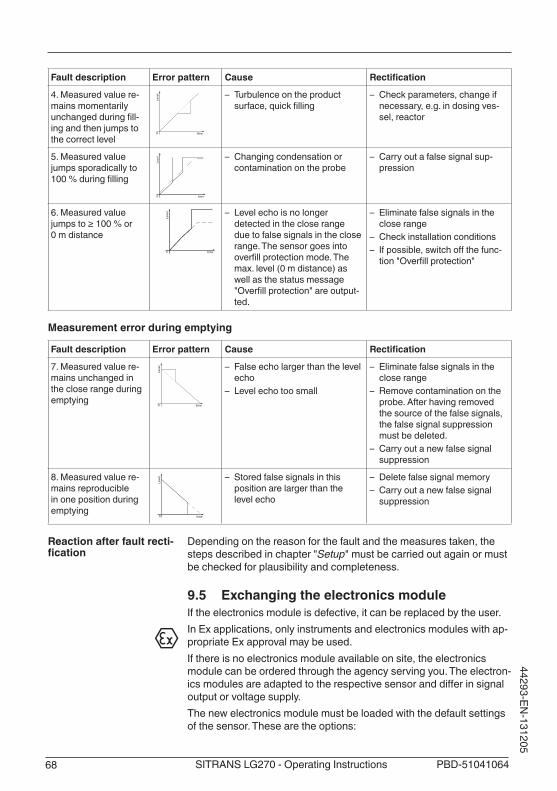
68 PBD-51041064SITRANS LG270 - Operating Instructions
44293-EN-131205
Fault description Error pattern Cause Rectification
4. Measured value re-mains momentarily unchangedduringfill-ing and then jumps to the correct level
Leve
l
time0
– Turbulence on the product surface,quickfilling
– Check parameters, change if necessary, e.g. in dosing ves-sel, reactor
5. Measured value jumps sporadically to 100%duringfilling
Level
time0
– Changing condensation or contamination on the probe
– Carry out a false signal sup-pression
6. Measured value jumpsto≥100%or0 m distance
Leve
l
time0
– Level echo is no longer detected in the close range due to false signals in the close range. The sensor goes into overfillprotectionmode.Themax.level(0mdistance)aswell as the status message "Overfillprotection"areoutput-ted.
– Eliminate false signals in the close range
– Check installation conditions – Ifpossible,switchoffthefunc-tion"Overfillprotection"
Measurement error during emptying
Fault description Error pattern Cause Rectification
7. Measured value re-mains unchanged in the close range during emptying
Leve
l
time0
– False echo larger than the level echo
– Level echo too small
– Eliminate false signals in the close range
– Remove contamination on the probe. After having removed the source of the false signals, the false signal suppression must be deleted.
– Carry out a new false signal suppression
8. Measured value re-mains reproducible in one position during emptying
Leve
l
time0
– Stored false signals in this position are larger than the level echo
– Delete false signal memory – Carry out a new false signal
suppression
Depending on the reason for the fault and the measures taken, the steps described in chapter "Setup" must be carried out again or must be checked for plausibility and completeness.
9.5 Exchanging the electronics moduleIf the electronics module is defective, it can be replaced by the user.In Ex applications, only instruments and electronics modules with ap-propriate Ex approval may be used.If there is no electronics module available on site, the electronics module can be ordered through the agency serving you. The electron-icsmodulesareadaptedtotherespectivesensoranddifferinsignaloutput or voltage supply.The new electronics module must be loaded with the default settings of the sensor. These are the options:
Reaction after fault recti-fication

69PBD-51041064 SITRANS LG270 - Operating Instructions
4429
3-EN
-131
205
• In the factory• Or on site by the user
In both cases, the serial number of the sensor is needed. The serial numbers are stated on the type label of the instrument, on the inside of the housing as well as on the delivery note.Whenloadingonsite,firstofalltheorderdatamustbedownloadedfromtheInternet(seeoperatinginstructionsmanual"Electronics module").
9.6 Exchange or shorten cable/rodThecableorrod(meas.part)oftheprobecanbeshortened,ifneces-sary. To loosen the rod or cable you need a fork spanner with spanner width 13.1. Loosentherodorcablebyapplyingaforkspannertotheflat
surfaces(SW13),providecounterforcewithanotherforkspanner(SW13)
2. Unscrew the loosened rod or cable manually.3. Place the enclosed new double washer onto the thread.
Caution:Make sure that the two components of the double washer remain together.4. Screw the new rod and the new cable manually to the thread on
theprocessfitting.5. Exert counterforce with the second fork spanner and tighten the
ororcableontheflatsurfaceswithatorqueof20Nm(15lbfft).
Exchanging the cable/rod

70 PBD-51041064SITRANS LG270 - Operating Instructions
44293-EN-131205
Fig. 37: Exchange cable or rod
Information:Pleasemaintainthespecifiedtorquesothatthemax.tensilestrengthremains.6. Enter new probe length and if necessary the new probe type and
thencarryoutafreshadjustment(see"Setup procedure, Carry-ing out min. adjustment - Carrying out max. adjustment").
The rod or cable of the probe can be shortened individually.1. Mark the requested length with mounted measuring rod.2. Cable:Loosenthepinsonthegravityweight(hexagon3)3. Cable: remove the pins4. Cable: Pull the cable out of the gravity weight5. Shortenthecable/rodwithacut-offwheelormetalsawatthe
marking.Takenoteofthespecificationsinthefollowingillustrationwhen shortening the cable.
6. Cable with gravity weight: Shift the cable according to the drawing into the gravity weight
7. Cable with gravity weight: Fasten cable with the pins, torque 7 Nm (5.16lbfft)Cable with centering weight: Fasten cable with the pins, torque 7Nm(5.16lbfft)andfixtheclampingpartonthecenteringweight.
Shorten cable/rod

71PBD-51041064 SITRANS LG270 - Operating Instructions
4429
3-EN
-131
205
8. Enter new probe length and then carry out a fresh adjustment (see"Setup procedure, Carrying out min. adjustment - Carrying out max. adjustment").
41
1
2 2 3A B C
45 m
m
(1.7
7")
100
mm
(3
.94"
)
25 m
m
(0.9
8")
50
mm
(1
.97"
)
Fig. 38: Shortening the cable probeA Gravity weight - cable ø 4 mmB Gravity weight - cable ø 2 mmC Centering weight - cable ø 2 mm1 Threaded pins2 Thread M8 for eye-bolt3 Fixing screw - centering weight
9.7 Software updateThe following components are required to update the sensor soft-ware:
• Sensor• Voltage supply• HART modem• PC with PACTware• CurrentsensorsoftwareasfileYoucanfindtheactualsensorsoftwareaswellasdetailedinfor-mation of the procedure in the download area on our homepage: www.siemens.com.Youcanfindinformationabouttheinstallationinthedownloadfile.
Caution:Instruments with approvals can be bound to certain software ver-sions.Thereforemakesurethattheapprovalremainseffectivewithasoftware update.Youcanfinddetailedinformationinthedownloadareaonourhome-page: www.siemens.com.
9.8 How to proceed in case of repairIf it is necessary to repair the instrument, please contact Siemens MilltronicsProcessInstruments.Youfindthelocationsonourhome-page "www.siemens.com/processautomation".

72 PBD-51041064SITRANS LG270 - Operating Instructions
44293-EN-131205
10 Dismounting
10.1 Dismounting stepsWarning:Before dismounting, be aware of dangerous process conditions such as e.g. pressure in the vessel or pipeline, high temperatures, cor-rosive or toxic products etc.Take note of chapters "Mounting" and "Connecting to power supply" and carry out the listed steps in reverse order.
10.2 DisposalThe instrument consists of materials which can be recycled by spe-cialised recycling companies. We use recyclable materials and have designed the parts to be easily separable.Correctdisposalavoidsnegativeeffectsonhumansandtheenviron-ment and ensures recycling of useful raw materials.Materials: see chapter "Technical data"If you have no way to dispose of the old instrument properly, please contact us concerning return and disposal.
WEEE directive 2002/96/EGThis instrument is not subject to the WEEE directive 2002/96/EG and the respective national laws. Pass the instrument directly on to a spe-cialised recycling company and do not use the municipal collecting points. These may be used only for privately used products according to the WEEE directive.

73PBD-51041064 SITRANS LG270 - Operating Instructions
4429
3-EN
-131
205
11 Supplement
11.1 Technical dataGeneral data316L corresponds to 1.4404 or 1.4435Materials, wetted parts
Ʋ Processfitting-rodversion 316LandAluminiumoxide-ceramic99.7%(Al2O3),HastelloyC22(2.4602)andAluminiumoxide-ceramic99.7%(Al2O3)
Ʋ Processfitting-cableversion 316LandAluminiumoxide-ceramic99.7%(Al2O3) Ʋ Rod:ø16mm(0.63in) 316LorHastelloyC22(2.4602) Ʋ Cable:ø2mm(0.079in) 316(1.4401) Ʋ Cable:ø4mm(0.157in) 316(1.4401) Ʋ Gravityweight(optionallyavailable) 316L Ʋ Centeringweight(optionallyavailable) 316L Ʋ Process seal on the instrument side (cable/rodleadthrough)
Ceramic-graphite
Ʋ Process seal On siteMaterials, non-wetted parts
Ʋ Plastic housing plasticPBT(Polyester) Ʋ Aluminium die-casting housing Aluminium die-casting AlSi10Mg, powder-coated - basis:
Polyester Ʋ Stainless steel housing - precision casting
316L
Ʋ Stainless steel housing, electropol-ished
316L
Ʋ Second line of defence Borosilicate glass GPC 540 Ʋ Seal between housing and housing cover
NBR(stainlesssteelhousing,precisioncasting),silicone(aluminium/plastichousing;stainlesssteelhousing,electropolished)
Ʋ Inspection window in housing cover (optional)
Polycarbonate(withExdversion:glass)
Ʋ Ground terminal 316LSecond line of defence
Ʋ Supporting material 316L Ʋ Glass potting Borosilicate glass GPC 540 Ʋ Contacts Hastelloy C22 Ʋ Helium leak rate < 10-6 mbar l/s Ʋ Pressure resistance See process pressure of the sensor
Ohmic contact Betweengroundterminal,processfittingandprobeProcessfittings
Ʋ Pipethread,cylindrical(ISO228T1) G1½ according to DIN 3852-A
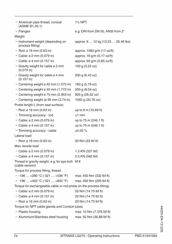
74 PBD-51041064SITRANS LG270 - Operating Instructions
44293-EN-131205
Ʋ American pipe thread, conical (ASMEB1.20.1)
1½ NPT
Ʋ Flanges e.g. DIN from DN 50, ANSI from 2"Weight
Ʋ Instrumentweight(dependingonprocessfitting)
approx.6…12kg(13.23…26.46lbs)
Ʋ Rod:ø16mm(0.63in) approx.1580g/m(17oz/ft) Ʋ Cable:ø2mm(0.079in) approx.16g/m(0.17oz/ft) Ʋ Cable:ø4mm(0.157in) approx.60g/m(0.65oz/ft) Ʋ Gravityweightforcableø2mm(0.079in)
100g(3.22oz)
Ʋ Gravityweightforcableø4mm(0.157in)
200g(6.43oz)
Ʋ Centeringweightø40mm(1.575in) 180g(5.79oz) Ʋ Centeringweightø45mm(1.772in) 250g(8.04oz) Ʋ Centeringweightø75mm(2.953in) 825g(26.52oz) Ʋ Centeringweight(ø95mm(3.74in) 1050g(33.76oz)
ProbelengthL(fromsealsurface) Ʋ Rod:ø16mm(0.63in) upto6m(19.69ft) Ʋ Trimming accuracy - rod ±1 mm Ʋ Cable:ø2mm(0.079in) upto75m(246.1ft) Ʋ Cable:ø4mm(0.157in) upto75m(246.1ft) Ʋ Trimming accuracy - cable ±0.05 %
Lateral load Ʋ Rod:ø16mm(0.63in) 30Nm(22lbfft)
Max. tensile load Ʋ Cable:ø2mm(0.079in) 1.5KN(337lbf) Ʋ Cable:ø4mm(0.157in) 2.5KN(562lbf)
Thread in gravity weight, e.g. for eye-bolt (cableversion)
M 8
Torqueforprocessfitting,thread Ʋ -196…+280°C(-321…+536°F) max.450Nm(332lbfft) Ʋ -196…+450°C(-321…+842°F) max.400Nm(295lbfft)
Torqueforexchangeablecableorrodprobe(intheprocessfitting) Ʋ Cable:ø2mm(0.079in) 20Nm(14.75lbfft) Ʋ Cable:ø4mm(0.157in) 20Nm(14.75lbfft) Ʋ Rod:ø16mm(0.63in) 20Nm(14.75lbfft)
Torque for NPT cable glands and Conduit tubes Ʋ Plastic housing max.10Nm(7.376lbfft) Ʋ Aluminium/Stainless steel housing max.50Nm(36.88lbfft)

75PBD-51041064 SITRANS LG270 - Operating Instructions
4429
3-EN
-131
205
Input variableMeasured variable Level of liquidsMin. dielectric constant of the medium
Ʋ Cable probes εr≥1.6 Ʋ Rod probes εr≥1.6
2
4
3
5
1
2
4
5
3
1
Fig. 39: Measuring ranges - SITRANS LG2701 Reference plane2 Probe length L3 Measuring range (default setting refers to the measuring range in water)4 Upper dead band (see diagrams under Accuracy - grey section)5 Lower dead band (see diagrams under Accuracy - grey section)
Output variableOutput signals 4 … 20 mA/HART - active; 4 … 20 mA/HART - passiveRange of the output signal 3.8…20.5mA/HART(defaultsetting)

76 PBD-51041064SITRANS LG270 - Operating Instructions
44293-EN-131205
Terminal voltage passive 9 … 30 V DCShortcircuit protection AvailablePotential separation AvailableSignal resolution 0.3 µAFailuresignalcurrentoutput(adjustable) Lastvalidmeasuredvalue,≥21.0mA,≤3.6mAMax. output current 21 mAStarting current ≤3.6mALoad(4…20mA/HART-active) <500ΩDamping(63%oftheinputvariable) 0 … 999 s, adjustableHARToutputvaluesaccordingtoHART7(defaultsetting)1)
Ʋ FirstHARTvalue(PV) Linearised percentage value, level Ʋ SecondHARTvalue(SV) Distance to the level Ʋ ThirdHARTvalue(TV) Measurement certainty, level Ʋ FourthHARTvalue(QV) Electronics temperature
Indication value - DIsplay and adjustment module2)
Ʋ Displayed value 1 Filling height - Level Ʋ Displayed value 2 Electronics temperature
Resolution, digital <1mm(0.039in)
Accuracy (according to DIN EN 60770-1)Process reference conditions according to DIN EN 61298-1
Ʋ Temperature +18…+30°C(+64…+86°F) Ʋ Relative humidity 45 … 75 % Ʋ Air pressure +860 … +1060 mbar/+86 … +106 kPa
(+12.5…+15.4psig)Installation reference conditions
Ʋ Min. distance to installations >500mm(19.69in) Ʋ Vessel metallic,ø1m(3.281ft),centricinstallation,process
fittingflushwiththevesselceiling Ʋ Medium Water/Oil(dielectricconstant~2.0)3)
Ʋ Installation Probe end does not touch the vessel bottomSensor parameter adjustment No gating out of false signals carried outTypical deviation - Interface measure-ment
±5mm(0.197in)
Typical deviation - Total level interface measurement
See following diagrams
Typical deviation - Level measurement4)5) See following diagrams
1) The output values can be assigned individually2) The indication values can be assigned individually3) Withinterfacemeasurement=2.04) Dependingontheinstallationconditions,therecanbedeviationswhichcanberectifiedwithanadaptationoftheadjustmentorachangeofthemeasuredvalueoffsetintheDTMservicemode
5) Thedeadbandscanbeoptimizesbyafalsesignalsuppression.

77PBD-51041064 SITRANS LG270 - Operating Instructions
4429
3-EN
-131
205
L
0-2�mm (-0.079")
2�mm (0.079")
15�mm (0.591")
-5�mm (-0.197")
0,3 m(11.811")
0,08 m(3.15")
1
0,015 m(0.591")
Fig. 40: Deviation SITRANS LG270 in rod version in water1 Dead band - no measurement possible in this areaL Probe length
L
2�mm(0.079")
-2�mm(0.079")
0
25�mm(0.984")
-25�mm(-0.984")
0,2 m(7.874")
0,15 m(5.906") 0,05 m
(1.968")
1 1
0,05 m(1.968")
Fig. 41: Deviation SITRANS LG270 in rod version in oil1 Dead band - no measurement possible in this areaL Probe length

78 PBD-51041064SITRANS LG270 - Operating Instructions
44293-EN-131205
0
2�mm(0.079")
-2�mm(-0.079")
15�mm(0.591")
10�mm(0.394")
0,08 m(3.15")
0,3 m(11.811")
0,1m(3.94")
L
1
Fig. 42: Deviation SITRANS LG270 in cable version in water1 Dead band - no measurement possible in this areaL Probe length
L
0
-15�mm(-0.591")
2�mm(0.079")
-2�mm(-0.079")
25�mm(0.984")
0,2 m(7.874")
0,15 m(5.906") 0,08 m
(3.15")
0,1 m(3.937")
1 1
Fig. 43: Deviation SITRANS LG270 in cable version 2 mm (0.079 in), in oil1 Dead band - no measurement possible in this areaL Probe length

79PBD-51041064 SITRANS LG270 - Operating Instructions
4429
3-EN
-131
205
L
0
-15�mm(-0.591")
2�mm(0.079")
-2�mm(-0.079")
25�mm(0.984")
0,2 m(7.874")
0,15 m(5.906") 0,15 m
(5.906")
0,1 m(3.937")
1 1
Fig. 44: Deviation SITRANS LG270 in cable version 4 mm (0.157 in), in oil1 Dead band - no measurement possible in this areaL Probe length
Repeatability ≤±1mm
VariablesinfluencingmeasurementaccuracySpecificationsforthedigitalmeasuredvalueTemperature drift - Digital output ±3 mm/10 K relating to the max. measuring range or
max.10mm(0.394in)Additional deviation through electromag-netic interference acc. to EN 61326
<±10mm(<±0.394in)
Specificationsapplyalsotothecurrentoutput6)
Temperature drift - Current output ±0.03 %/10 K relating to the 16 mA span max. ±0.3 %Deviation on the current output through analogue/digital conversion
< ±15 µA
Additional deviation through electromag-netic interference acc. to EN 61326
< ±150 µA
InfluenceofthesuperimposedgasandpressuretotheaccuracyThe propagation speed of the radar impulses in gas or vapour above the medium is reduced by highpressure.Thiseffectdependsonthesuperimposedgasorvapourandisespeciallylargeatlow temperatures.Thefollowingtableshowstheresultingdeviationforsometypicalgasesandvapours.Thespecifiedvalues refer to the distance. Positive values mean that the measured distance is too large, negative values that the measured distance is too small.
6) Alsoforthesecondcurrentoutput(optional)

80 PBD-51041064SITRANS LG270 - Operating Instructions
44293-EN-131205
Gas phase Temperature Pressure
10 bar (145 psig)
50 bar (725 psig)
100 bar (1450 psig)
200 bar (2900 psig)
400 bar (5800 psig)
Air 20 °C/68 °F 0.22 % 1.2 % 2.4 % 4.9 % 9.5 %
200 °C/392 °F 0.13 % 0.74 % 1.5 % 3.0 % 6.0 %
400 °C/752 °F 0.08 % 0.52 % 1.1 % 2.1 % 4.2 %
Hydrogen 20 °C/68 °F 0.10 % 0.61 % 1.2 % 2.5 % 4.9 %
200 °C/392 °F 0.05 % 0.37 % 0.76 % 1.6 % 3.1 %
400 °C/752 °F 0.03 % 0.25 % 0.53 % 1.1 % 2.2 %
Steam(satu-ratedsteam)
100 °C/212 °F - - - - -
180 °C/356 °F 2.1 % - - - -
264 °C/507 °F 1.44 % 9.2 % - - -
366 °C/691 °F 1.01 % 5.7 % 13.2 % 76.0 % -
Characteristics and performance dataMeasuring cycle time < 500 msStep response time7) ≤3sMax.filling/emptyingspeed 1 m/min
Ambient conditionsAmbient, storage and transport tempera-ture
-40…+80°C(-40…+176°F)
Process conditionsFortheprocessconditions,pleasealsonotethespecificationsonthetypelabel.Thelowestvaluealways applies.Themeasurementerrorfromtheprocessconditionsisinthespecifiedpressureandtemperaturerange of below 1 %.Vesselpressurerelatingtotheflangenominal stage
see supplementary instructions manual "Flanges ac-cording to DIN-EN-ASME-JIS"
Process pressure -1 … +400 bar/-100 … +40000 kPa (-14.5…+5800psig),dependingontheprocessfitting
Process temperature -196…+280°C(-321…+536°F)
7) Time span after a sudden measuring distance change by max. 0.5 m in liquid applications, max 2 m with bulk solidsapplications,untiltheoutputsignalhastakenforthefirsttime90%ofthefinalvalue(IEC61298-2).

81PBD-51041064 SITRANS LG270 - Operating Instructions
4429
3-EN
-131
205
1
20°C
(32°F)
-40°C(-104°F)
65°C(149°F)
80°C(176°F)
280°C(536°F)
250°C(482°F)
190°C(374°F)
34
-196°C(-321°F)
-80°C(-112°F)
55°C(131°F)
Fig. 45: Ambient temperature - process temperature (version -196 … +280 °C/-321 … +536 °F)1 Ambient temperature2 Process temperature (depending on the seal material)3 Maximum permissible temperature - standard4 Limited temperature range - plastic housing and stainless steel housing, electropolished
Process temperature -196…+450°C(-321…+842°F)The measurement error from the process conditions is in thespecifiedpressureandtemperaturerangeofbelow1 %.
1
20°C
(32°F)
-40°C(-104°F)
80°C(176°F)
450°C(842°F)
220°C(428°F)
34
-196°C(-384.8°F)
-20°C(-68°F)
-110°C(-230°F)
35°C(95°F)
Fig. 46: Ambient temperature - process temperature (version -196 … +450 °C/-321 … +842 °F)1 Ambient temperature2 Process temperature (depending on the seal material)3 Maximum permissible temperature - standard4 Limited temperature range - plastic housing and stainless steel housing, electropolished

82 PBD-51041064SITRANS LG270 - Operating Instructions
44293-EN-131205
2
1-100°C
(-148°F)-196°C
(-321°F)
100 bar(1450 psig)
200 bar(2900 psig)
400 bar(5800 psig) 380 bar
(5510 psig)356 bar
(5160 psig)
0°C(32°F)
200°C(392°F)
100°C(212°F)
280°C(536°F)
Fig. 47: Process pressure - process temperature (version -196 … +280 °C/-321 … +536 °F)1 Process temperature (depending on the seal material)2 Process pressure
2
1-100°C
(-148°F)-196°C
(-321°F)
100 bar(1450 psig)
200 bar(2900 psig)
300 bar(4350 psig)
400 bar(5800 psig) 380 bar
(5510 psig)350 bar
(5070 psig)
0°C(32°F)
200°C(392°F)
100°C(212°F)
400°C(752°F)
300°C(572°F)
320 bar(4640 psig)
450°C(842°F)
Fig. 48: Process pressure - process temperature (version -196 … +450 °C/-321 … +842 °F)1 Process temperature (depending on the seal material)2 Process pressure
Vibration resistance Ʋ Instrument housing 4gat5…200HzaccordingtoEN60068-2-6(vibration
withresonance) Ʋ Rod probe 1gwith5…200HzaccordingEN60068-2-6(vibration
atresonance)withrodlength50cm(19.69in)Shock resistance

83PBD-51041064 SITRANS LG270 - Operating Instructions
4429
3-EN
-131
205
Ʋ Instrument housing 100g,6msaccordingtoEN60068-2-27(mechanicalshock)
Ʋ Rod probe 25g,6msaccordingtoEN60068-2-27(mechanicalshock)withrodlength50cm(19.69in)
Electromechanical data - version IP 66/IP 67Options of the cable entry
Ʋ Cable gland M20 x 1.5 Ʋ Cablediameter(options) 5…9mm(0.20…0.35in)
6…12mm(0.24…0.47in)10…14mm(0.39…0.55in)
Ʋ Cable entry ½ NPT Ʋ Blind plug M20 x 1.5; ½ NPT
Plug options Ʋ Supplyandsignalcircuit(onlywithlowvoltage)
M12 x 1 plug
Ʋ Indication circuit M12 x 1 plugWirecross-section(spring-loadedterminals)
Ʋ Massive wire, cord 0.2…2.5mm²(AWG24…14) Ʋ Stranded wire with end sleeve 0.2…1.5mm²(AWG24…16)
Display and adjustment moduleDisplay element Display with backlightMeasured value indication
Ʋ Number of digits 5 Ʋ Sizeofdigits WxH=7x13mm
Adjustment elements 4 keysProtection rating
Ʋ unassembled IP 20 Ʋ mounted into the housing without cover
IP 40
Materials Ʋ Housing ABS Ʋ Inspection window Polyester foil
Integrated clockDate format Day.Month.YearTime format 12 h/24 hTimezoneExfactory CETRate deviation max. 10.5 min/year
Measurement electronics temeratureResolution 1°C(1.8°F)
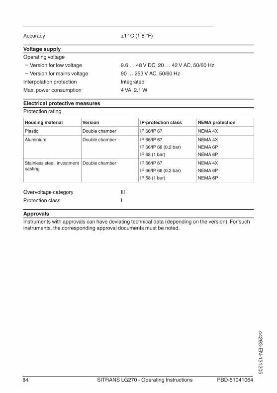
84 PBD-51041064SITRANS LG270 - Operating Instructions
44293-EN-131205
Accuracy ±1°C(1.8°F)
Voltage supplyOperating voltage
Ʋ Version for low voltage 9.6…48VDC,20…42VAC,50/60Hz Ʋ Version for mains voltage 90…253VAC,50/60Hz
Interpolation protection IntegratedMax. power consumption 4 VA; 2.1 W
Electrical protective measuresProtection rating
Housing material Version IP-protection class NEMA protection
Plastic Double chamber IP 66/IP 67 NEMA4X
Aluminium Double chamber IP 66/IP 67IP66/IP68(0.2bar)IP68(1bar)
NEMA4XNEMA 6PNEMA 6P
Stainless steel, investment casting
Double chamber IP 66/IP 67IP66/IP68(0.2bar)IP68(1bar)
NEMA4XNEMA 6PNEMA 6P
Overvoltage category IIIProtection class I
ApprovalsInstrumentswithapprovalscanhavedeviatingtechnicaldata(dependingontheversion).Forsuchinstruments, the corresponding approval documents must be noted.
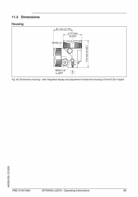
85PBD-51041064 SITRANS LG270 - Operating Instructions
4429
3-EN
-131
205
11.2 Dimensions
Housing
1
~ 81 mm (3.19")ø 77 mm(3.03")
114
mm
(4.4
9")
M20x1,5/½ NPT
M16x1,5
Fig. 49: Dimensions housing - with integrated display and adjustment module the housing is 9 mm/0.35 in higher

86 PBD-51041064SITRANS LG270 - Operating Instructions
44293-EN-131205
SITRANS LG270, cable version with gravity weight
4
1 2 3
SW 60(2.36")
G1½ /1½ NPT
L
35m
m(1
.38"
)31
2 m
m (1
2.28
")
237
mm
(9.3
3")
ø 4 mm(0.16")
ø 4 mm(0.16")
ø 20 mm(0.79") 1
00 m
m
(3.9
4")
ø 20 mm(0.79") 1
00 m
m
(3.9
4")
L
50 m
m(1
.97"
)
ø 2 mm (0.08")
ø 16 mm(0.63")
ø 20 mm(0.79")
ø 20 mm(0.79")
ø 16 mm(0.63")
ø 20 mm(0.79")
ø 16 mm(0.63")
Fig. 50: SITRANS LG270, threaded version with gravity weight (all gravity weights with thread M8 for eye-bolt)L Sensor length, see chapter "Technical data"1 Cable ø 4 mm (0.157 in), temperature version -196 … +280 °C (-321 … 536 °F)2 Cable ø 2 mm (0.079 in)3 Cable ø 4 mm (0.157 in), temperature version -196 … +450 °C (-321 … 842 °F)4 Max. height of the vessel isolation

87PBD-51041064 SITRANS LG270 - Operating Instructions
4429
3-EN
-131
205
SITRANS LG270, cable version with centering weight
G1½ /1½ NPT
L
35m
m(1
.38"
)31
2 m
m (1
2.28
")
X
ø 4 mm(0.16")
30 m
m(1
.18"
)
ø 2 mm / (0.08")
SW 60(2.36")
45 m
m(1
.77"
)
237
mm
(9.3
3")
X
ø 4 mm(0.16")
30 m
m(1
.18"
)
ø 2 mm / (0.08")
L
1 2
3
Fig. 51: SITRANS LG270, threaded version with centering weightL Sensor length, see chapter "Technical data"x ø 40 mm (1.57 in)
ø 45 mm (1.77 in)ø 75 mm (2.95 in)ø 95 mm (3.74 in)
1 Cable ø 2 mm (0.079 in)/cable ø 4 mm (0.157 in), temperature version -196 … +280 °C (-321 … 536 °F) - (see supplementary instructions "Centering")
2 Cable ø 2 mm (0.079 in)/cable ø 4 mm (0.157 in), temperature version -196 … +450 °C (-321 … 842 °F) - (see supplementary instructions "Centering")
3 Max. height of the vessel isolation

88 PBD-51041064SITRANS LG270 - Operating Instructions
44293-EN-131205
SITRANS LG270, rod version
SW 60(2.36")
G1½ /1½ NPT
ø 16mm(0.63")
L
35m
m(1
.38"
)31
2 m
m (1
2.28
")
45 m
m(1
.77"
)
237
mm
(9.3
3")
ø 16 mm (0.63")
L
1 2
3
Fig. 52: SITRANS LG270, threaded versionL Sensor length, see chapter "Technical data"1 Rod ø 16 mm (0.63 in), temperature version -196 … +280 °C (-321 … 536 °F)2 Rod ø 16 mm (0.63 in), temperature version -196 … +450 °C (-321 … 842 °F)3 Max. height of the vessel isolation

89PBD-51041064 SITRANS LG270 - Operating Instructions
4429
3-EN
-131
205
INDEX
AAccessories
– Display and adjustment module 11 – External display and adjustment unit 12
Adjustment – Max. adjustment 35, 36 – Min. adjustment 36, 37
Adjustment system 30Application 34, 35Application area 9
BBacklight 43Block adjustment 42
CCheck output signal 66Connecting
– Mechanically 13 – To the PC 53
Connection cable 22Connection procedure 23Connection technology 23Copy sensor settings 49Current output, adjustment 40Current output Min./Max. 41Current output mode 40Currentoutput,size40Curve indication
– Echo curve 45
DDamping 37Date of manufacture 51Date/Time 46Default values 47Deviation 66
EEcho curve memory 61Echo curve of the setup 46EDD(EnhancedDeviceDescription)60Electronics compartment, double chamber housing 25Error codes 64Event memory 61
FFactory calibration date 51False signal suppression 41
Faultrectification66Functional principle 9
GGas phase 35Grounding 22
HHART address 50HART variables 41
IInflowingmedium16Installation position 14
KKey function 29
LLanguage 43Linearization37
MMain menu 33Meas. reliability 44Measured value indication 43Measured value memory 61Measurement loop name 33
NNAMUR NE 107 65
– Failure 63
PPeak value indicator 44PIN 46Probe length 34Probe type 50Protection class 22
QQuick setup 31
RRead out info 51Repair 71Replacement parts
– Electronics module 12 – Rod extension 12 – Spacer 12
Reset 47

90 PBD-51041064SITRANS LG270 - Operating Instructions
44293-EN-131205
SScaling measured value 39, 40Sensor characteristics 51Sensor status 44Simulation 45Special parameters 50Status messages - NAMUR NE 107 62
TTerminal compartment
– Double chamber housing 25, 26Type of medium 34Type plate 8
UUnits 34
VVessel insulation 18Voltage supply 22, 84

Notes
91PBD-51041064 SITRANS LG270 - Operating Instructions
4429
3-EN
-131
205

Siemens AGIndustry sector1954 Technology DriveP.O. Box 4225Peterborough. ONCanada K9J7B1email: [email protected]
www.siemens.com/processautomation
Subject to change without prior noticePBD-51041064 Rev. 1.0
© Siemens AG 2013
For more informationwww.siemens.com/level
www.siemens.com/weighing
PBD-51041064Printed in Canada