operating instructions profibus pa pressure transmitter · · 2017-12-122 safety instructions ......
TRANSCRIPT

Operating instructionsProfibus PA pressure transmitter
PMP0xx
7044
85 /
00
05 /
2009
UK
2
Contents1 Preliminary note....................................................................................................3
1. Symbols used ...................................................................................................32 Safety instructions ................................................................................................33 Functions and features .........................................................................................44 Function ...............................................................................................................45 Installation ............................................................................................................56 Electrical connection.............................................................................................77 Set-up ...................................................................................................................88 Parameter setting .................................................................................................9
8.1 Block model: Pressure transmitter with Profibus PA profile 3.01 ..................108.2 Physical Block (PB) ...................................................................................... 118.3 Analogue Input Block (AIB) ..........................................................................128.4 Pressure Transducer Block (PTB) ................................................................138.5 VIEW_1 Parameter (VIEW) ..........................................................................148.6 Installation and maintenance parameters (I&M parameters) .......................158.7 Typical parameter setting procedures ..........................................................16
8.7.1 Zero point adjustment ..........................................................................168.7.2 Damping of the signal measured .........................................................168.7.3 Input of the unit of measurement for the pressure ..............................178.7.4 Min/max monitoring (lag indicator function) .........................................178.7.5 Monitoring the threshold value ............................................................188.7.6 Simulation ............................................................................................18
9 Operation ............................................................................................................199.1 Communication ............................................................................................199.2 Diagnosis and trouble-shooting ....................................................................21
10 Scale drawing ...................................................................................................2311 Technical data ...................................................................................................24
3
UK
1 Preliminary note1. Symbols used
► Instruction> Reaction, result[…] Designation of buttons, switches or indications→ Cross-reference
Important noteNon-compliance can result in malfunctions or interference.InformationSupplementary note.
2 Safety instructionsPlease read this document prior to installing the unit. Ensure that the product is • suitable for your application without any restrictions. If the operating instructions or the technical data are not adhered to, personal • injury and/or damage to property may occur. Check in all applications that the product materials (→ 10 Technical data) are • compatible with the media to be measured.Adhere to the remarks for safe use in hazardous areas (→ ATEX operating • instructions).
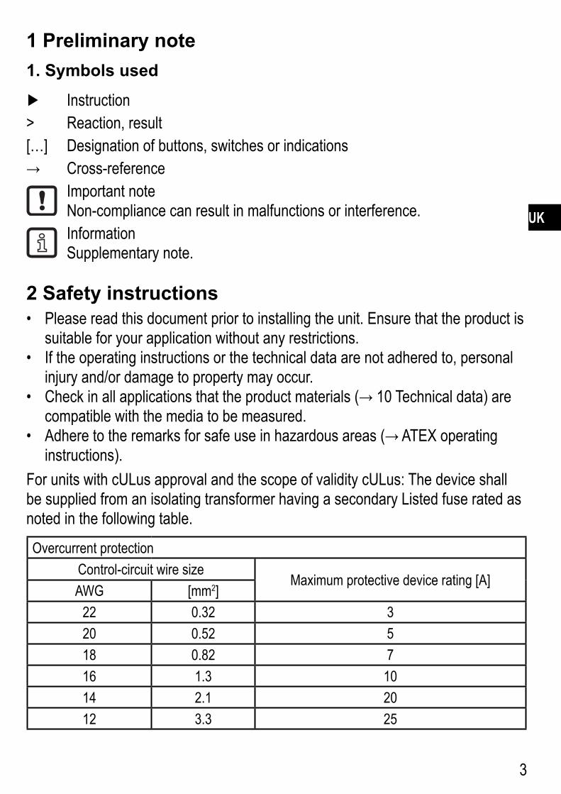
For units with cULus approval and the scope of validity cULus: The device shall be supplied from an isolating transformer having a secondary Listed fuse rated as noted in the following table.
Overcurrent protectionControl-circuit wire size
Maximum protective device rating [A]AWG [mm2]
22 0.32 320 0.52 518 0.82 716 1.3 1014 2.1 2012 3.3 25
4
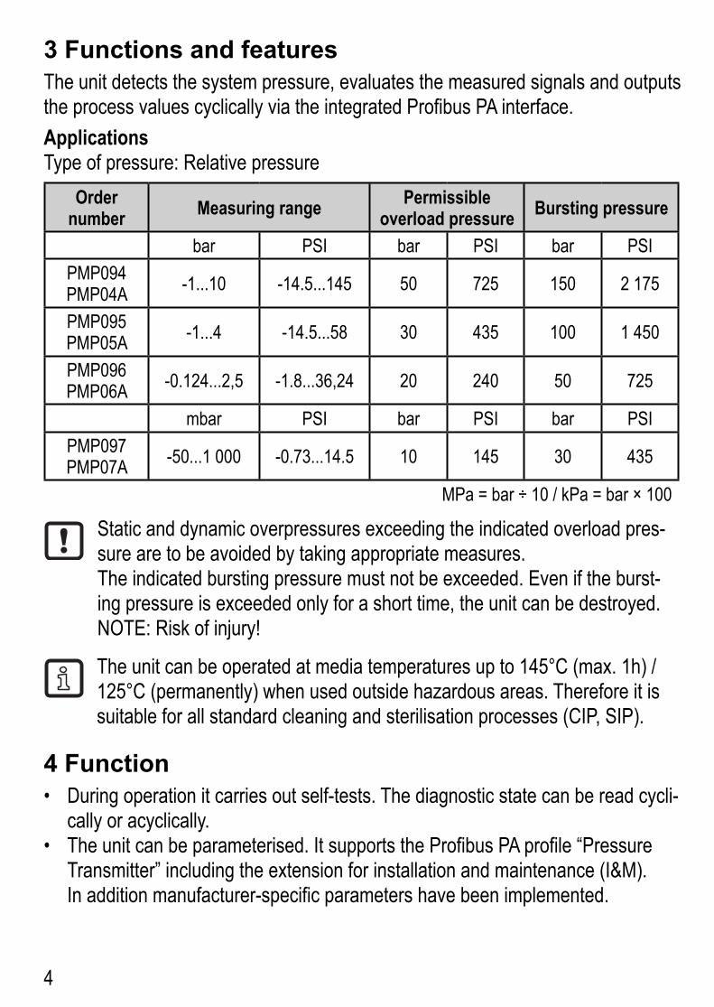
3 Functions and featuresThe unit detects the system pressure, evaluates the measured signals and outputs the process values cyclically via the integrated Profibus PA interface.Applications Type of pressure: Relative pressure
Order number Measuring range Permissible
overload pressure Bursting pressure
bar PSI bar PSI bar PSIPMP094PMP04A -1...10 -14.5...145 50 725 150 2 175
PMP095PMP05A -1...4 -14.5...58 30 435 100 1 450
PMP096PMP06A -0.124...2,5 -1.8...36,24 20 240 50 725
mbar PSI bar PSI bar PSIPMP097PMP07A -50...1 000 -0.73...14.5 10 145 30 435
MPa = bar ÷ 10 / kPa = bar × 100
Static and dynamic overpressures exceeding the indicated overload pres-sure are to be avoided by taking appropriate measures.The indicated bursting pressure must not be exceeded. Even if the burst-ing pressure is exceeded only for a short time, the unit can be destroyed. NOTE: Risk of injury!
The unit can be operated at media temperatures up to 145°C (max. 1h) / 125°C (permanently) when used outside hazardous areas. Therefore it is suitable for all standard cleaning and sterilisation processes (CIP, SIP).
4 Function During operation it carries out self-tests. The diagnostic state can be read cycli-• cally or acyclically.The unit can be parameterised. It supports the Profibus PA profile “Pressure • Transmitter” including the extension for installation and maintenance (I&M).In addition manufacturer-specific parameters have been implemented.

5
UK
5 InstallationEnsure that no pressure is applied to the installation while mounting or removing the sensor� NOTE: The fieldbus measuring value “0 digits” does not mean that no pressure is applied to the installation!
Installation locationWe recommend horizontal installation for high medium temperatures�•To monitor a tank: If possible, mount •the sensor at the bottom of the tank (1)�Do not mount near an agitator (2), a •pump (3) or in the spout of the tank (3)!
�
�
�
Aseptoflex adapters ensure that the sensor can be connected to different process connections� (The adapters have to be ordered sepa-rately as accessories�)Mounting operation:
Mount the adapter (B) to the sensor� ►Fix sensor + adapter by means of a ►coupling nut, a clamp flange or similar (A) to the process connection�
�
�
If it is not possible to slide the fixing element (A) down over the top of the sensor: slide it up over the bottom of the sensor before the adapter is mounted�

6
Mounting the Aseptoflex adapter
��
�
��
�
1 2
3
Grease the following parts with the paste supplied (C): ►thread and sealing areas of the unit� -sealing areas and O-ring of the adapter� -
Food-grade paste (USDA-H1 84-201) is supplied�Make sure that the O-ring (D) is correctly positioned�Screw the sensor into the adapter until it is hand-tight� Do not damage the ►sealing chamfers�Clamp sensor and adapter into a clamping device (E)� Tighten the clamping ►device only slightly so that the adapter does not warp�Tighten the sensor using a spanner until you can feel the end stop (correspond- ►ing to a maximum tightening torque of 25 Nm / 18 ftlb)� Note: Do not overtight-en� This can have an adverse effect on the sealing�
NOTE: A guarantee for a long-term stable and maintenance-free fitting with no bug traps in the hygienic sealing of the metal seal (Aseptoflex connection) is only valid for once-only mounting�Welding adapter
First weld the adapter, then mount the sensor� Follow the instructions included ►with the adapter�
7
UK
6 Electrical connectionThe unit must be connected by a qualified electrician�The national and international regulations for the installation of electrical equipment must be adhered to�Voltage supply to EN50178, SELV, PELV� For use in hazardous areas : The regulations of FISCO (Fieldbus Intrinsi-cally Safe Concept) must be adhered to� For details refer to the separately suppliedATEXoperatinginstructions.
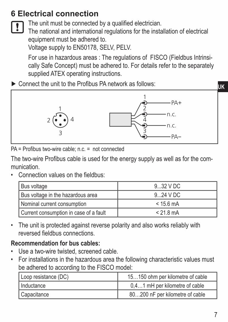
Connect the unit to the Profibus PA network as follows: ►
PA = Profibus two-wire cable; n�c� = not connectedThe two-wire Profibus cable is used for the energy supply as well as for the com-munication�
Connection values on the fieldbus:•Bus voltage 9���32 V DCBus voltage in the hazardous area 9���24 V DCNominal current consumption < 15�6 mACurrent consumption in case of a fault < 21�8 mA
The unit is protected against reverse polarity and also works reliably with •reversed fieldbus connections�
Recommendation for bus cables:Use a two-wire twisted, screened cable� •For installations in the hazardous area the following characteristic values must •be adhered to according to the FISCO model:Loop resistance (DC) 15…150 ohm per kilometre of cableInductance 0,4…1 mH per kilometre of cableCapacitance 80…200 nF per kilometre of cable
8
For maximum EMC protection, e� g� near frequency converters we recommend •to connect the housing and the cable screen via an equipotential bonding conductor�For use in the hazardous area: Meet the requirements of the relevant stand-•ards for grounding�
Further information about the structure and grounding of the network:Profibus PA specification EN 50170�•PNO guideline “Profibus PA User and Installation Guideline”�•
7 Set-upA valid bus address must be assigned to the unit so that it is recognised as a network component� The preset address 126 dec only acts for set-up in an exist-ing network�You need configuration software of type Profibus master class 2 for addressing�Bus addressing / online addressing (Unit is installed in the active bus segment)
Create a life list of the network segment using your configuration program� ►The newly installed unit has been programmed by the factory with the address 126 dec� This address only acts for set-up in an existing network�Assign a valid address between 0 and 125 dec� ►
Only one non addressed unit should be connected to the running network� If two or more units with the supplied address 126 dec are installed, incorrect bus accesses will occur� The units cannot be put into correct operation!
9
UK
8 Parameter settingFor parameter setting you need configuration software of type Profibus master class 2, such as SIMATIC® PDM (Process Device Manager from Siemens)�You will also need the matching object description file to access the profile-specific and the manufacturer-specific parameters:
Device description file (DD) for SIMATIC - ® PDM�You will find the file on the provided CD-ROM� Additionally it is avaliable on the ifm homepage http://www�ifm�com in “Service” / “Download”�
If you change parameters during operation, the operating principle of the plant will be influenced�
Ensure that there will be no malfunctions in your plant� ►
A block model and the tables on the following pages provide an overview of the possible parameters and their meanings� They are based on the Profibus PA profile “Pressure Transmitter” including the extension for installation and maintenance (I&M)�In addition the manufacturer-specific parameters for extended functions and for more convenient operation are available�

10
8.1 Block model: Pressure transmitter with Profibus PA profile 3.01
�
P = system pressureS = sensor with linearisation and temperature compensationifm = manufacturer-specific parameters ifm electronicPTB = pressure transducer blockAIB = analogue input block
11
UK
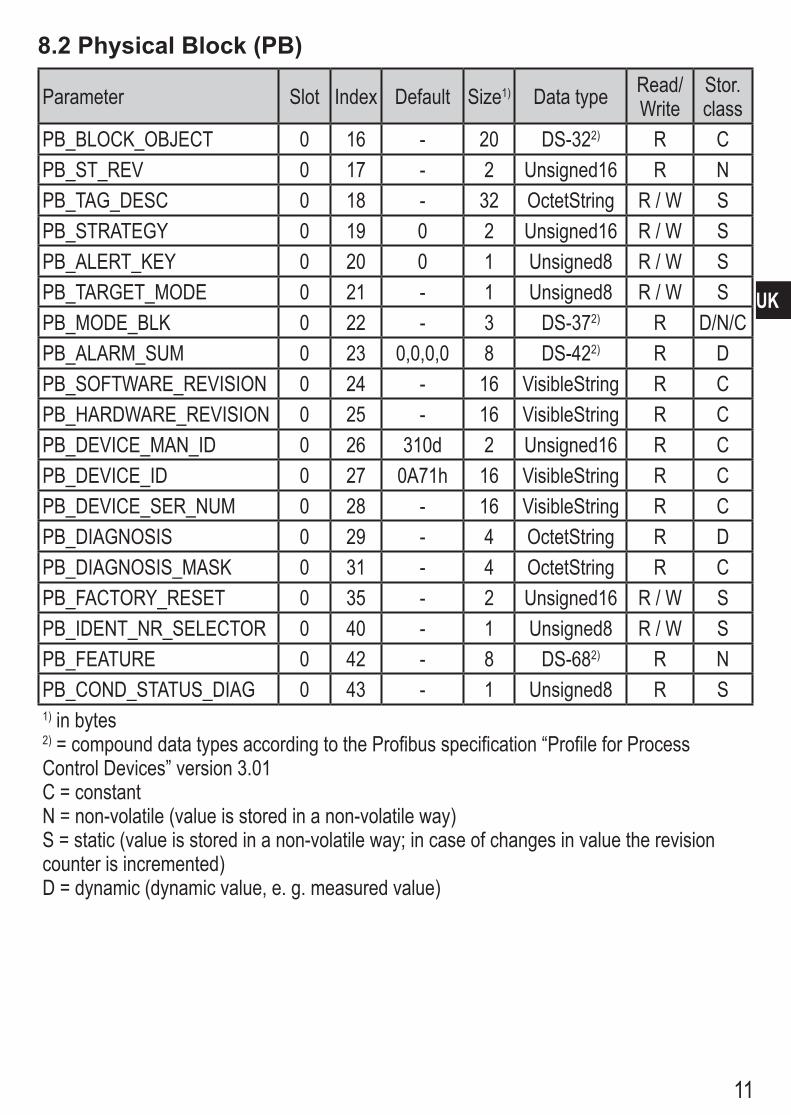
8.2 Physical Block (PB)
Parameter Slot Index Default Size1) Data type Read/Write
Stor� class
PB_BLOCK_OBJECT 0 16 - 20 DS-322) R CPB_ST_REV 0 17 - 2 Unsigned16 R NPB_TAG_DESC 0 18 - 32 OctetString R / W SPB_STRATEGY 0 19 0 2 Unsigned16 R / W SPB_ALERT_KEY 0 20 0 1 Unsigned8 R / W SPB_TARGET_MODE 0 21 - 1 Unsigned8 R / W SPB_MODE_BLK 0 22 - 3 DS-372) R D/N/CPB_ALARM_SUM 0 23 0,0,0,0 8 DS-422) R DPB_SOFTWARE_REVISION 0 24 - 16 VisibleString R CPB_HARDWARE_REVISION 0 25 - 16 VisibleString R CPB_DEVICE_MAN_ID 0 26 310d 2 Unsigned16 R CPB_DEVICE_ID 0 27 0A71h 16 VisibleString R CPB_DEVICE_SER_NUM 0 28 - 16 VisibleString R CPB_DIAGNOSIS 0 29 - 4 OctetString R DPB_DIAGNOSIS_MASK 0 31 - 4 OctetString R CPB_FACTORY_RESET 0 35 - 2 Unsigned16 R / W SPB_IDENT_NR_SELECTOR 0 40 - 1 Unsigned8 R / W SPB_FEATURE 0 42 - 8 DS-682) R NPB_COND_STATUS_DIAG 0 43 - 1 Unsigned8 R S1) in bytes2) = compound data types according to the Profibus specification “Profile for Process Control Devices” version 3�01C = constantN = non-volatile (value is stored in a non-volatile way)S = static (value is stored in a non-volatile way; in case of changes in value the revision counter is incremented)D = dynamic (dynamic value, e� g� measured value)

12
8.3 Analogue Input Block (AIB)
Parameter Slot Index Default Size1) Data type Read/Write
Stor� class
AI_BLOCK_OBJECT 1 16 - 20 DS-322) R CAI_ST_REV 1 17 - 2 Unsigned16 R NAI_TAG_DESC 1 18 - 32 OctetString R / W SAI_STRATEGY 1 19 0 2 Unsigned16 R / W SAI_ALERT_KEY 1 20 0 1 Unsigned8 R / W SAI_TARGET_MODE 1 21 - 1 Unsigned8 R / W SAI_MODE_BLK 1 22 - 3 DS-372) R D/N/CAI_ALARM_SUM 1 23 0,0,0,0 8 DS-422) R DAI_BATCH 1 24 0,0,0,0 10 DS-672) R / W SAI_OUT 1 26 - 5 101 R / W DAI_PV_SCALE 1 27 *) 8 Array of float R / W SAI_OUT_SCALE 1 28 *) 11 DS-362) R / W SAI_LIN_TYPE 1 29 0 1 Unsigned8 R / W SAI_CHANNEL 1 30 - 2 Unsigned16 R / W SAI_PV_FTIME 1 32 0 4 Float R / W SAI_ALARM_HYS 1 35 0,5%VMR 4 Float R / W SAI_HI_HI_LIM 1 37 MAX 4 Float R / W SAI_HI_LIM 1 39 MAX 4 Float R / W SAI_LO_LIM 1 41 MIN 4 Float R / W SAI_LO_LO_LIM 1 43 MIN 4 Float R / W SAI_HI_HI_ALM 1 46 0 16 DS-392) R DAI_HI_ALM 1 47 0 16 DS-392) R DAI_LO_ALM 1 48 0 16 DS-392) R DAI_LO_LO_ALM 1 49 0 16 DS-392) R DAI_SIMULATE 1 50 OFF 6 DS-502) R / W S1) in bytes; 2) = compound data types according to the Profibus specification “Profile for Process Control Devices” version 3�01*) Minimum / maximum value according to the measuring range of the unit; default value for the unit of measurement is bar (AI_OUT_SCALE_UNIT = 1137)C = constantN = non-volatile (value is stored in a non-volatile way)S = static (value is stored in a non-volatile way; in case of changes in value the revision counter is incremented)D = dynamic (dynamic value, e� g� measured value)VMR=finalvalueofthemeasuringrange;MAX=maximumvalue;MIN=minimumvalue
13
UK
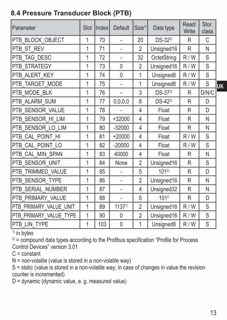
8.4 Pressure Transducer Block (PTB)
Parameter Slot Index Default Size1) Data type Read/Write
Stor� class
PTB_BLOCK_OBJECT 1 70 - 20 DS-322) R CPTB_ST_REV 1 71 - 2 Unsigned16 R NPTB_TAG_DESC 1 72 - 32 OctetString R / W SPTB_STRATEGY 1 73 0 2 Unsigned16 R / W SPTB_ALERT_KEY 1 74 0 1 Unsigned8 R / W SPTB_TARGET_MODE 1 75 - 1 Unsigned8 R / W SPTB_MODE_BLK 1 76 - 3 DS-372) R D/N/CPTB_ALARM_SUM 1 77 0,0,0,0 8 DS-422) R DPTB_SENSOR_VALUE 1 78 - 4 Float R DPTB_SENSOR_HI_LIM 1 79 +32000 4 Float R NPTB_SENSOR_LO_LIM 1 80 -32000 4 Float R NPTB_CAL_POINT_HI 1 81 +20000 4 Float R / W SPTB_CAL_POINT_LO 1 82 -20000 4 Float R / W SPTB_CAL_MIN_SPAN 1 83 40000 4 Float R NPTB_SENSOR_UNIT 1 84 None 2 Unsigned16 R SPTB_TRIMMED_VALUE 1 85 - 5 1012) R DPTB_SENSOR_TYPE 1 86 - 2 Unsigned16 R NPTB_SERIAL_NUMBER 1 87 - 4 Unsigned32 R NPTB_PRIMARY_VALUE 1 88 - 5 1012 R DPTB_PRIMARY_VALUE_UNIT 1 89 11371) 2 Unsigned16 R / W SPTB_PRIMARY_VALUE_TYPE 1 90 0 2 Unsigned16 R / W SPTB_LIN_TYPE 1 103 0 1 Unsigned8 R / W S1) in bytes2) = compound data types according to the Profibus specification “Profile for Process Control Devices” version 3�01C = constantN = non-volatile (value is stored in a non-volatile way)S = static (value is stored in a non-volatile way; in case of changes in value the revision counter is incremented)D = dynamic (dynamic value, e� g� measured value)
14
Parameter Slot Index Default Size1) Data type Read/Write
Stor� class
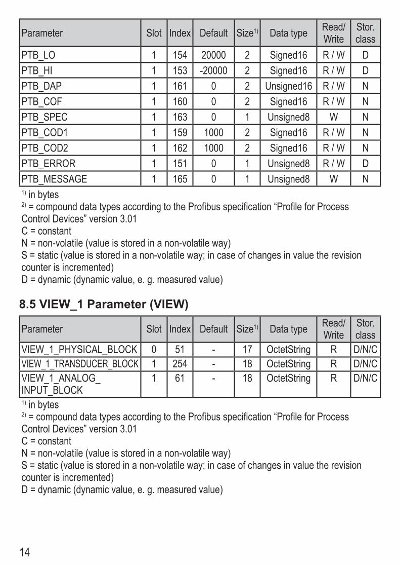
PTB_LO 1 154 20000 2 Signed16 R / W DPTB_HI 1 153 -20000 2 Signed16 R / W DPTB_DAP 1 161 0 2 Unsigned16 R / W NPTB_COF 1 160 0 2 Signed16 R / W NPTB_SPEC 1 163 0 1 Unsigned8 W NPTB_COD1 1 159 1000 2 Signed16 R / W NPTB_COD2 1 162 1000 2 Signed16 R / W NPTB_ERROR 1 151 0 1 Unsigned8 R / W DPTB_MESSAGE 1 165 0 1 Unsigned8 W N1) in bytes2) = compound data types according to the Profibus specification “Profile for Process Control Devices” version 3�01C = constantN = non-volatile (value is stored in a non-volatile way)S = static (value is stored in a non-volatile way; in case of changes in value the revision counter is incremented)D = dynamic (dynamic value, e� g� measured value)
8.5 VIEW_1 Parameter (VIEW)
Parameter Slot Index Default Size1) Data type Read/Write
Stor� class
VIEW_1_PHYSICAL_BLOCK 0 51 - 17 OctetString R D/N/CVIEW_1_TRANSDUCER_BLOCK 1 254 - 18 OctetString R D/N/CVIEW_1_ANALOG_ INPUT_BLOCK
1 61 - 18 OctetString R D/N/C
1) in bytes2) = compound data types according to the Profibus specification “Profile for Process Control Devices” version 3�01C = constantN = non-volatile (value is stored in a non-volatile way)S = static (value is stored in a non-volatile way; in case of changes in value the revision counter is incremented)D = dynamic (dynamic value, e� g� measured value)
15
UK
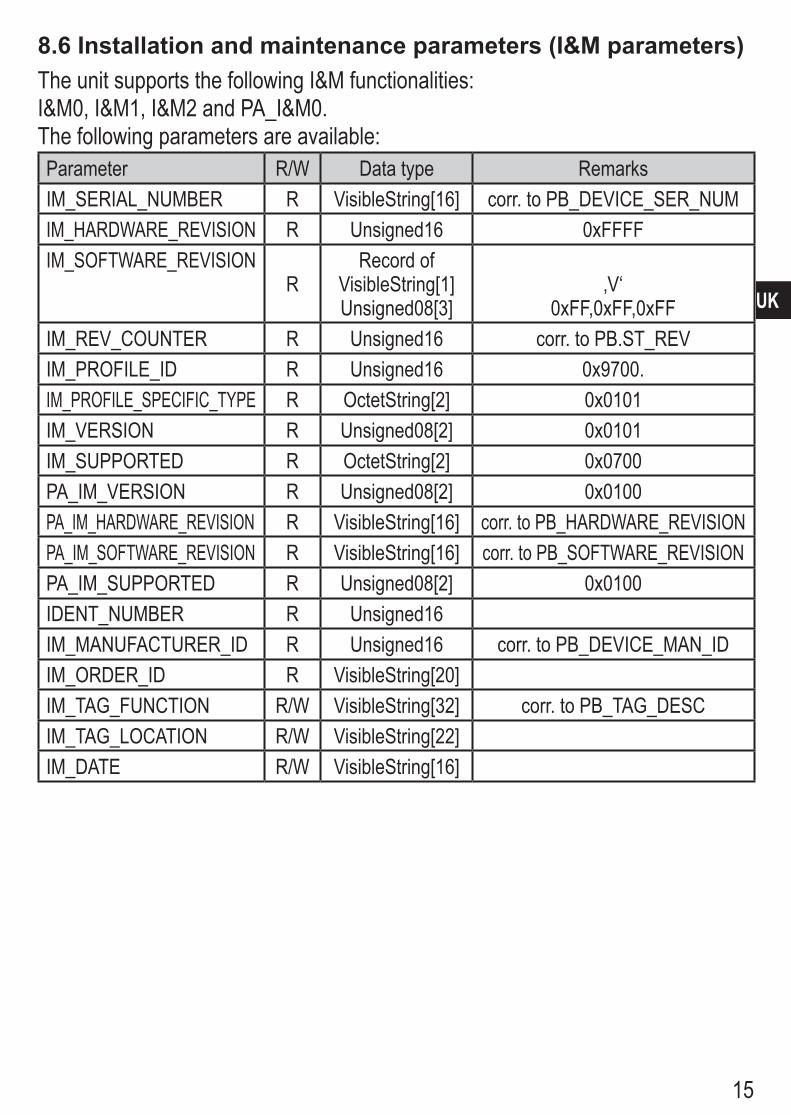
8.6 Installation and maintenance parameters (I&M parameters)The unit supports the following I&M functionalities:I&M0, I&M1, I&M2 and PA_I&M0� The following parameters are available:Parameter R/W Data type RemarksIM_SERIAL_NUMBER R VisibleString[16] corr� to PB_DEVICE_SER_NUMIM_HARDWARE_REVISION R Unsigned16 0xFFFFIM_SOFTWARE_REVISION
RRecord of
VisibleString[1]Unsigned08[3]
‚V‘0xFF,0xFF,0xFF
IM_REV_COUNTER R Unsigned16 corr� to PB�ST_REVIM_PROFILE_ID R Unsigned16 0x9700�IM_PROFILE_SPECIFIC_TYPE R OctetString[2] 0x0101IM_VERSION R Unsigned08[2] 0x0101IM_SUPPORTED R OctetString[2] 0x0700PA_IM_VERSION R Unsigned08[2] 0x0100PA_IM_HARDWARE_REVISION R VisibleString[16] corr� to PB_HARDWARE_REVISIONPA_IM_SOFTWARE_REVISION R VisibleString[16] corr� to PB_SOFTWARE_REVISIONPA_IM_SUPPORTED R Unsigned08[2] 0x0100IDENT_NUMBER R Unsigned16IM_MANUFACTURER_ID R Unsigned16 corr� to PB_DEVICE_MAN_IDIM_ORDER_ID R VisibleString[20]IM_TAG_FUNCTION R/W VisibleString[32] corr� to PB_TAG_DESCIM_TAG_LOCATION R/W VisibleString[22]IM_DATE R/W VisibleString[16]
16
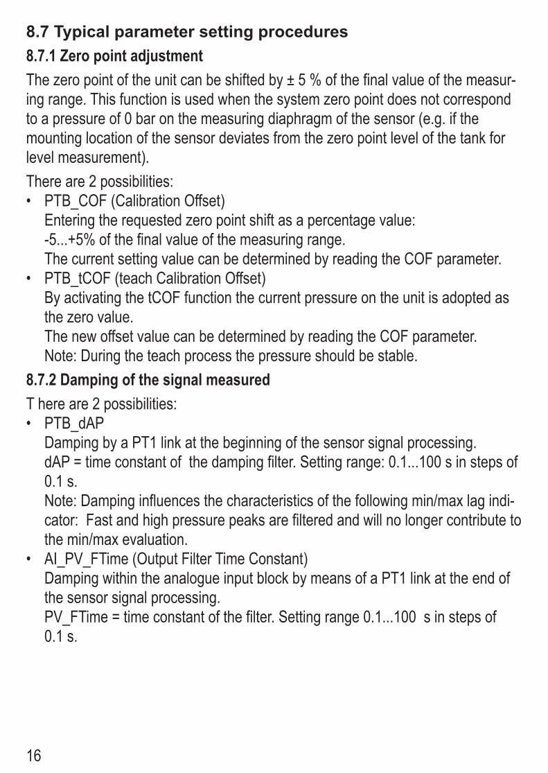
8.7 Typical parameter setting procedures8.7.1 Zero point adjustmentThe zero point of the unit can be shifted by ± 5 % of the final value of the measur-ing range� This function is used when the system zero point does not correspond to a pressure of 0 bar on the measuring diaphragm of the sensor (e�g� if the mounting location of the sensor deviates from the zero point level of the tank for level measurement)�There are 2 possibilities:
PTB_COF (Calibration Offset)•Entering the requested zero point shift as a percentage value:-5���+5% of the final value of the measuring range� The current setting value can be determined by reading the COF parameter�PTB_tCOF (teach Calibration Offset)•By activating the tCOF function the current pressure on the unit is adopted as the zero value� The new offset value can be determined by reading the COF parameter�Note: During the teach process the pressure should be stable�
8.7.2 Damping of the signal measuredT here are 2 possibilities:
PTB_dAP•Damping by a PT1 link at the beginning of the sensor signal processing�dAP = time constant of the damping filter� Setting range: 0�1���100 s in steps of 0�1 s�Note: Damping influences the characteristics of the following min/max lag indi-cator: Fast and high pressure peaks are filtered and will no longer contribute to the min/max evaluation�AI_PV_FTime (Output Filter Time Constant)•Damping within the analogue input block by means of a PT1 link at the end of the sensor signal processing�PV_FTime = time constant of the filter� Setting range 0�1���100 s in steps of 0�1 s�

17
UK
8.7.3 Input of the unit of measurement for the pressurePTB_Primary_Value_Unit•The following units can be set:
Profibus-ID Unit Explanation1137 bar bar = 100 kPa1141 PSI pound-force per square inch
= 0�45359237 × 9�80665 ÷ 0�02542 Pa1138 mbar millibar = 1 hPa1132 MPa megapascal = 106 PA1133 kPa kilopascal = 103 PA1146 inH2O inches of water column1149 mmH2O millimetres of water column*1155 inHg inches of mercury column1157 mmHg millimetres of mercury column1152 ftH2O feet of water column1140 atm atmosphere = 101325�0 Pa
*Onlyforunitswithafinalvalueofthemeasuringrange≤2.5bar.
If the unit is changed, all pressure-specific parameters will be converted and displayed in the new unit� Note:By changing the unit of measurement the digital output value will also change� This influences the subsequent controller�The unit of measurement defined by means of the parameter PTB_Primary_Value_Unit serves as reference for all internal operations�Inaddition,aseparateoutputunitcanbedefinedwhenscalingtheoutputs(→analogue input block, parameter AI_OUT_SCALE)�
8.7.4 Min/max monitoring (lag indicator function)The highest and lowest measured pressure values are stored and can be read�
PTB_HI (display of the highest measured value)�•PTB_LO (display of the lowest measured value)�•Resetting the memory: Activating parameters, overwriting with “0”�
18
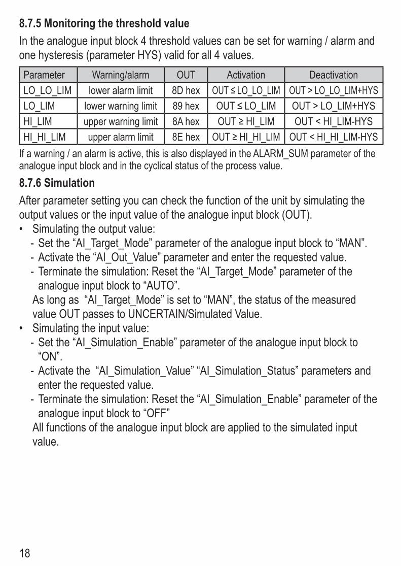
8.7.5 Monitoring the threshold valueIn the analogue input block 4 threshold values can be set for warning / alarm and one hysteresis (parameter HYS) valid for all 4 values�Parameter Warning/alarm OUT Activation DeactivationLO_LO_LIM lower alarm limit 8D hex OUT≤LO_LO_LIM OUT > LO_LO_LIM+HYSLO_LIM lower warning limit 89 hex OUT≤LO_LIM OUT > LO_LIM+HYSHI_LIM upper warning limit 8A hex OUT≥HI_LIM OUT < HI_LIM-HYSHI_HI_LIM upper alarm limit 8E hex OUT≥HI_HI_LIM OUT < HI_HI_LIM-HYS
If a warning / an alarm is active, this is also displayed in the ALARM_SUM parameter of the analogue input block and in the cyclical status of the process value�8.7.6 SimulationAfter parameter setting you can check the function of the unit by simulating the output values or the input value of the analogue input block (OUT)�
Simulating the output value:•Set the “AI_Target_Mode” parameter of the analogue input block to “MAN”� -Activate the “AI_Out_Value” parameter and enter the requested value� -Terminate the simulation: Reset the “AI_Target_Mode” parameter of the -analogue input block to “AUTO”�
As long as “AI_Target_Mode” is set to “MAN”, the status of the measured value OUT passes to UNCERTAIN/Simulated Value�Simulating the input value:•
Set the “AI_Simulation_Enable” parameter of the analogue input block to -“ON”�Activate the “AI_Simulation_Value” “AI_Simulation_Status” parameters and -enter the requested value�Terminate the simulation: Reset the “AI_Simulation_Enable” parameter of the -analogue input block to “OFF”
All functions of the analogue input block are applied to the simulated input value�
19
UK
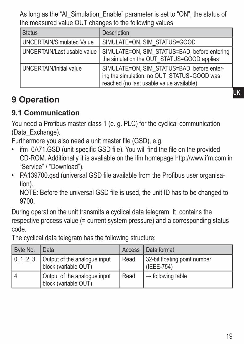
As long as the “AI_Simulation_Enable” parameter is set to “ON”, the status of the measured value OUT changes to the following values:Status DescriptionUNCERTAIN/Simulated Value SIMULATE=ON, SIM_STATUS=GOODUNCERTAIN/Last usable value SIMULATE=ON, SIM_STATUS=BAD, before entering
the simulation the OUT_STATUS=GOOD appliesUNCERTAIN/Initial value SIMULATE=ON, SIM_STATUS=BAD, before enter-
ing the simulation, no OUT_STATUS=GOOD was reached (no last usable value available)
9 Operation9.1 CommunicationYou need a Profibus master class 1 (e� g� PLC) for the cyclical communication (Data_Exchange)�Furthermore you also need a unit master file (GSD), e�g�
ifm_0A71�GSD (unit-specific GSD file)� You will find the file on the provided •CD-ROM� Additionally it is avaliable on the ifm homepage http://www�ifm�com in “Service” / “Download”)�PA139700�gsd (universal GSD file available from the Profibus user organisa-•tion)�NOTE: Before the universal GSD file is used, the unit ID has to be changed to 9700�
During operation the unit transmits a cyclical data telegram� It contains the respective process value (= current system pressure) and a corresponding status code�The cyclical data telegram has the following structure:Byte No� Data Access Data format0, 1, 2, 3 Output of the analogue input
block (variable OUT)Read 32-bit floating point number
(IEEE-754)4 Output of the analogue input
block (variable OUT)Read →followingtable

20
Status-Code [bin] Unit state Meaning1 0 0 0 0 0 X X GOOD/OK Everything OK1 0 0 0 1 0 0 1 GOOD/advis�
Alarm/LOMeasured value OK, LO_LIM warning of the analogue input block active�
1 0 0 0 1 0 1 0 GOOD/advis� Alarm/HI
Measured value OK, HI_LIM-warning of the analogue input block active�
1 0 0 0 1 1 0 1 GOOD/active crit� Alarm/LO
Measured value OK, LO_LO_LIM-alarm of the analogue input block active�
1 0 0 0 1 1 1 0 GOOD/active crit� Alarm/HI
Measured value OK, HI_HI_LIM-alarm of the analogue input block active�
0 1 0 0 0 1 X X UNCERTAIN/last usable value
Last valid value is output (fail safe mode): The Primary_Value provided by the transducer block or the value simulated in the analogue input block has the “BAD” state�
0 1 1 0 0 0 X X UNCERTAIN/ simulated value
Simulated Value: Simulation in the analogue input block active or mode of the analogue input block = “MAN” (OUT can be set by the user)�
0 1 0 0 1 1 X X UNCERTAIN/ Initial value
Initial value is output because the Primary_Value provided by the trans-ducer block or the value simulated by the analogue input block has the “BAD” state, and since Reset or Power-On, no value with the “GOOD” state has been available� Fail safe mode active but “last usable value” is not available�
0 0 0 1 1 1 X X Bad/Out of Service
System error detected� The diagnostic messages provide further information�
(x: don‘t care)
21
UK
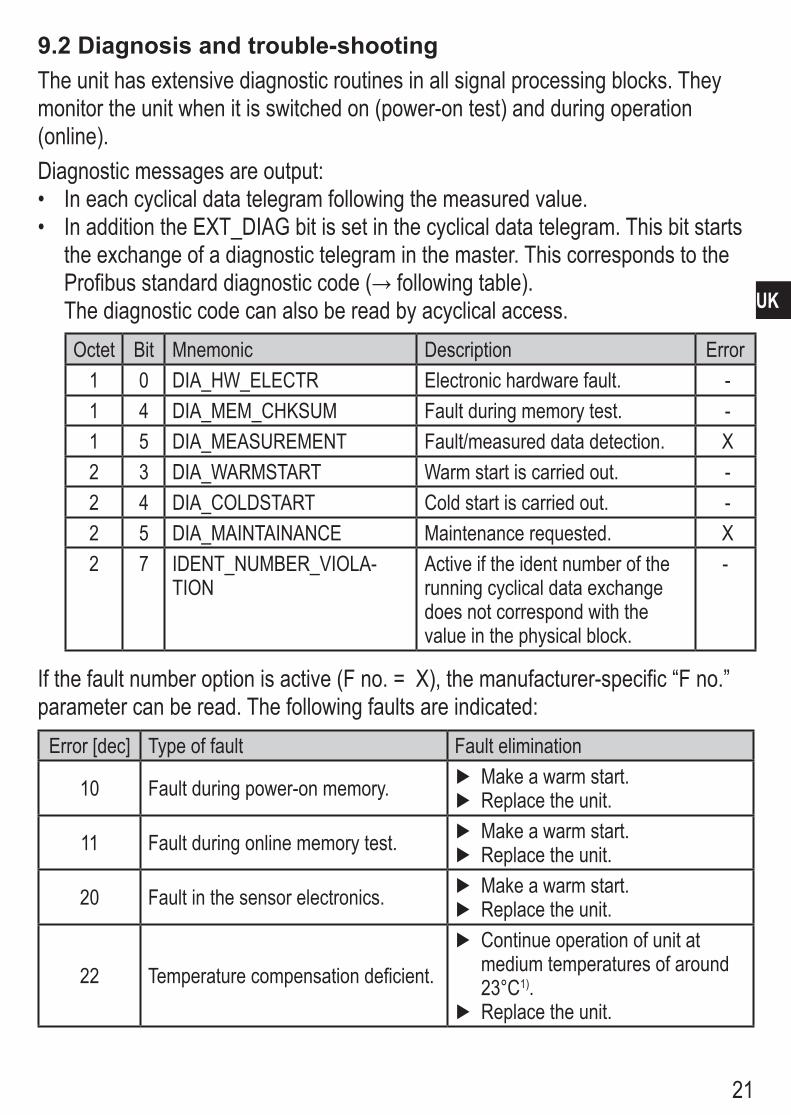
9.2 Diagnosis and trouble-shootingThe unit has extensive diagnostic routines in all signal processing blocks� They monitor the unit when it is switched on (power-on test) and during operation (online)�Diagnostic messages are output:
In each cyclical data telegram following the measured value� •InadditiontheEXT_DIAGbitissetinthecyclicaldatatelegram.Thisbitstarts•the exchange of a diagnostic telegram in the master� This corresponds to the Profibusstandarddiagnosticcode(→followingtable).The diagnostic code can also be read by acyclical access�Octet Bit Mnemonic Description Error
1 0 DIA_HW_ELECTR Electronic hardware fault� - 1 4 DIA_MEM_CHKSUM Fault during memory test� - 1 5 DIA_MEASUREMENT Fault/measured data detection� X2 3 DIA_WARMSTART Warm start is carried out� - 2 4 DIA_COLDSTART Cold start is carried out� - 2 5 DIA_MAINTAINANCE Maintenance requested� X2 7 IDENT_NUMBER_VIOLA-
TIONActive if the ident number of the running cyclical data exchange does not correspond with the value in the physical block�
-
Ifthefaultnumberoptionisactive(Fno.=X),themanufacturer-specific“Fno.”parameter can be read� The following faults are indicated:
Error [dec] Type of fault Fault elimination
10 Fault during power-on memory� Make a warm start� ►Replace the unit� ►
11 Fault during online memory test� Make a warm start� ►Replace the unit� ►
20 Fault in the sensor electronics� Make a warm start� ►Replace the unit� ►
22 Temperature compensation deficient�
Continue operation of unit at ►medium temperatures of around 23°C1)�Replace the unit� ►

22
Error [dec] Type of fault Fault elimination
53 Measured value above operating range�
Decrease pressure� ►Replace the unit� ►
54 Measured value below operating range�
Increase pressure� ►Replace the unit� ►
73 Measurement error > 2%
Unit can be further operated at ►decreased accuracy�Check measurement diaphragm ►for deposits�Replace the unit� ►
93 Medium temperature out ofoperating range�
Keep the specified temperature ►range�
1) The temperature influence increases to the same extent as the medium temperature rises above 23°C or drops below 23°C �
A restart of the sensor can be forced by means of the Profibus “PB_FACTORY_RESET” PA profile parameter in the physical block of the sensor�The following reset codes are available:
Reset code [dec] 1 = factory reset•The sensor starts again and loads its default settings for the static and non- -volatile parameters� Dynamic parameters are newly initialised� -The address setting is not changed� -
Reset code [dec] 2506 = warm start•The sensor is started again� All static and non-volatile parameters are set to -the value last set� Dynamic parameters are newly initialised�The address setting is not changed� -
Reset Code [dec] 2712 = address reset•The bus address of the unit is immediately reset to 126 dec� -Note: an active cyclical data transfer will be interrupted� -

23
UK
10 Scale drawing
����
��
��
�������
��� ��
���
� �
� �� �
�
Dimensions are in millimeters (25�4 mm = 1 inch)1: Aseptoflex sealing edge2: Aseptoflex thread3: Grounding screw (only for PMP0xA)
24
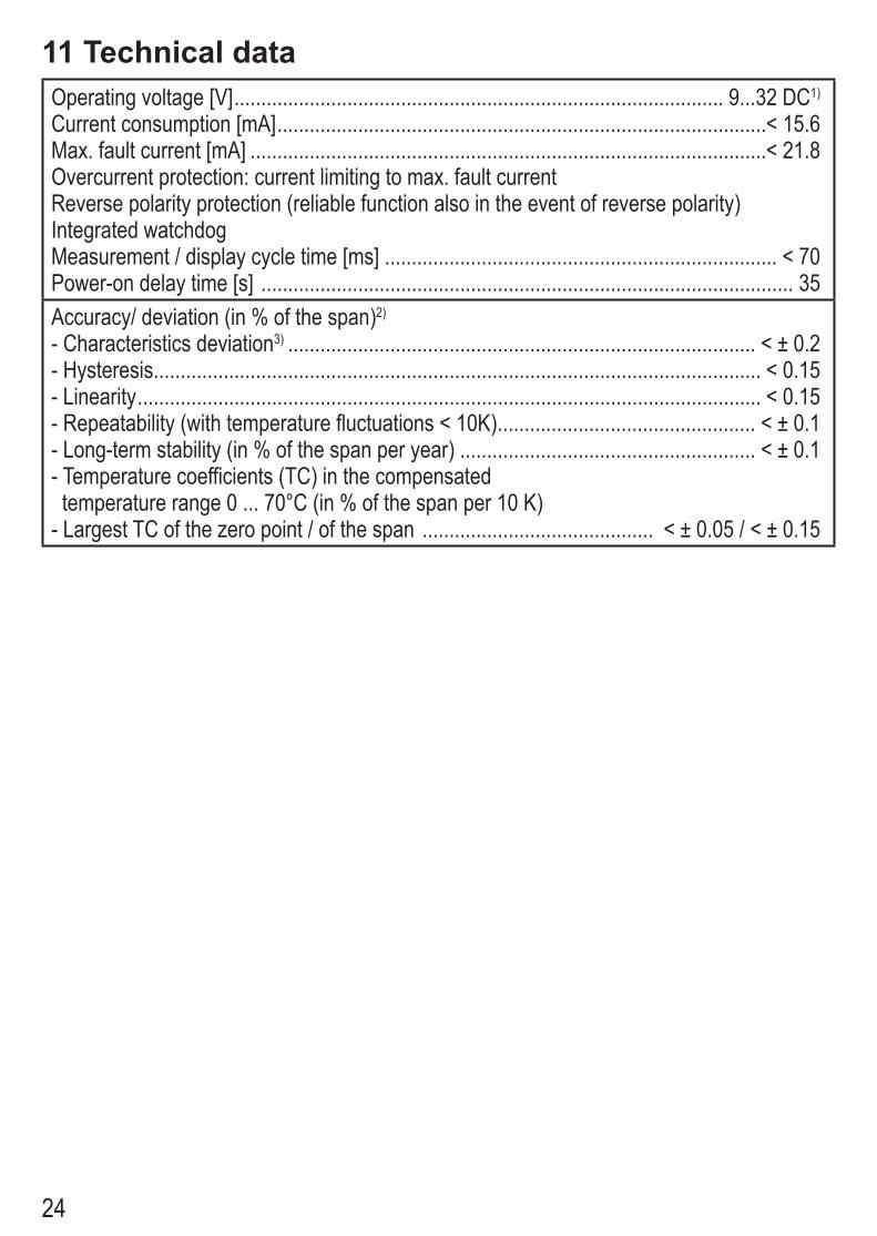
11 Technical dataOperating voltage [V] ������������������������������������������������������������������������������������������� 9���32 DC1) Current consumption [mA] �������������������������������������������������������������������������������������������< 15�6Max� fault current [mA] ������������������������������������������������������������������������������������������������< 21�8 Overcurrent protection: current limiting to max� fault currentReverse polarity protection (reliable function also in the event of reverse polarity)Integrated watchdogMeasurement / display cycle time [ms] ������������������������������������������������������������������������� < 70 Power-on delay time [s] ��������������������������������������������������������������������������������������������������� 35 Accuracy/ deviation (in % of the span)2)
- Characteristics deviation3) ��������������������������������������������������������������������������������������� < ± 0�2- Hysteresis ����������������������������������������������������������������������������������������������������������������� < 0�15- Linearity �������������������������������������������������������������������������������������������������������������������� < 0�15- Repeatability (with temperature fluctuations < 10K) ������������������������������������������������ < ± 0�1- Long-term stability (in % of the span per year) ������������������������������������������������������� < ± 0�1- Temperature coefficients (TC) in the compensated temperature range 0 ��� 70°C (in % of the span per 10 K) - Largest TC of the zero point / of the span ������������������������������������������� < ± 0�05 / < ± 0�15

25
UK
Materials (wetted parts)................................ stainless steel 316L / 1.4435, surface characteristics: Ra < 0.4 / Rz 4 ceramics (99.9 % Al2O3); PTFE Housing materials ...............................stainless steel 316L / 1.4404; PTFE; ULTEM; VitonProtection rating ............................................................................................ IP 68 / IP 69K Protection class ................................................................................................................ III Insulation resistance [MΩ] ........................................................................ > 100 (500 V DC)Shock resistance [g] .............................................................. 50 (DIN / IEC 68-2-27, 11ms)Vibration resistance [g] ............................................... 20 (DIN / IEC 68-2-6, 10 - 2000 Hz)Pressure cycles min. .......................................................................................... 100 million Operating temperature when used outside hazardous areas -25...85°Cfor PMP0xA when used in hazardous areas T4: -20...85°C
T5: -20...75°CT6: -20...60°C
Medium temperaturewhen used outside hazardous areas -25 ..125°C (145°C max. 1h)for PMP0xA when used in hazardous areas T4: -20...85°C
T5: -20...75°CT6: -20...60°C
Storage temperature [°C].................................................................................. -40 ... +100 EMC EN 61000-4-2 ESD: ....................................................................................... 4 / 8 kV EN 61000-4-3 HF radiated: ............................................................................ 10 V/m EN 61000-4-4 Burst: ........................................................................................... 2 kV EN 61000-4-5 Surge: .................................................................................. 0,5 / 1 kV EN 61000-4-6 HF conducted: ............................................................................ 10 V
1) Voltage supply to EN50178, SELV, PELVBus voltage in the hazardous area: 9... 24 V DC; adhere to the remarks for safe use in hazardous areas (→ ATEX operating instructions).
2) all indications are referred to a turn down of 1:1 3) linearity, incl. hysteresis and repeatability (limit value setting to DIN 16086)
Technical data and further information atwww.ifm.com → Select your country → Data sheet direct: