operating instructions - panasonic · microsoft® windows® xp professional sp3 is described as...
TRANSCRIPT
Before attempting to connect or operate this product, please read these instructions carefully and save this manual for future use.
The model number is abbreviated in some descriptions in this manual.
Operating InstructionsNetwork Video Encoder
Model No. WJ-GXE500WJ-GXE500E
ACT
10BASE-T/100BASE-TX
OPERATE
LINK
SD CARDERROR
Network Video EncoderWJ-GXE500

2
CONTENTSPreface ........................................................................ 3
About the user manuals .......................................... 3Trademarks and registered trademarks .................. 3Abbreviations .......................................................... 3Viewer software ....................................................... 4About the network security ..................................... 4
Equipped security functions ................................. 4Monitor images on a PC .............................................. 5
Monitor images from a single camera ..................... 5About the "Live" page ............................................. 7Monitor images from multiple cameras ................. 11
Record images on the SD memory card manually .... 12Action at an alarm occurrence .................................. 13
Alarm type .......................................................... 13Action at an alarm occurrence ........................... 13
Transmit images onto an FTP server ......................... 15Transmit an alarm image at an alarm occurrence (Alarm image transmission) ................................ 15Transmit images at a designated interval or period (FTP periodic image transmission) .......... 15Save images on the SD memory card when images have failed to be transmitted using the FTP periodic image transmission function ......... 16
Display the log list ..................................................... 17About the log list window ................................... 17
Playback of images on the SD memory card ............ 19About the playback page ................................... 19
Maintenance of the unit [Maintenance] ..................... 21Check the system log [System log] ....................... 21Upgrade the firmware [Upgrade] ........................... 22Reset the settings/Reboot the unit [Default reset] ........................................................ 23
Viewing Help .............................................................. 24Displaying the Help screen .................................... 24
Display the setup menu from a PC ........................... 25How to display the setup menu ............................ 25How to operate the setup menu ........................... 26About the setup menu window ............................. 27
Setup menu and its items ......................................... 28[Basic] page ............................................................... 30
[Basic] tab ............................................................. 30[SD memory card] tab ........................................... 31[Log] tab ................................................................ 33
[Image/Audio] page ................................................... 34[JPEG/H.264] tab .................................................. 34[JPEG/MPEG-4] tab .............................................. 37[Image/Position] tab .............................................. 40[Audio] tab ............................................................. 41[Coaxial/RS-485] tab ............................................. 42
[Multi-screen] page .................................................... 44[Multi-screen setup] tab ........................................ 44
[Alarm] page .............................................................. 45[Alarm] tab ............................................................. 45[VMD area] tab ....................................................... 46[Notification] tab .................................................... 48
[Advanced func.] page .............................................. 49[XML notification] tab ............................................ 49[Face detection] tab .............................................. 49
[User mng.] page ....................................................... 50[User auth.] tab ...................................................... 50[Host auth.] tab ...................................................... 50[System] tab .......................................................... 51
[Server] page ............................................................. 52[Mail] tab ................................................................ 52[FTP] tab ................................................................ 52[NTP] tab ............................................................... 53
[Network] page .......................................................... 54[Network] tab ......................................................... 54[DDNS] tab ............................................................ 55[SNMP] tab ............................................................ 56[FTP img. trans.] tab .............................................. 56
[Schedule] page ......................................................... 57[Schedule] tab ....................................................... 57
About the displayed system log ................................ 58Troubleshooting ......................................................... 60Appendix ................................................................... 68
Possible number of images that can be saved on the SD memory card (as indications) ............... 68How the logs and images are saved depending on the settings for "Alarm" .................................... 69How the logs and images are saved depending on the settings for "Manual" ................................. 70How the logs and images are saved depending on the settings for "FTP error" .............................. 71Directory structure of drive B ................................ 72
3
PrefaceAbout the user manualsThere are 2 sets of operating instructions for the WJ-GXE500 (NTSC model), WJ-GXE500E (PAL model) as follows. • InstallationGuide:Explainshowtoinstallandconnectdevices. •OperatingInstructions(PDF):Explainshowtoperformthesettingsandhowtooperatethisunit.
Adobe® Reader®isrequiredtoreadtheseoperatinginstructions(PDF)ontheprovidedCD-ROM.When the Adobe® Reader® is not installed on the PC, download the latest Adobe® Reader® from the Adobe web site and install it."WJ-GXE500" shown in the instructions and illustrations used in these operating instructions indicates the WJ-GXE500, WJ-GXE500E.The screens used in these operating instructions show the case of NTSC model.RefertothereadmefileontheprovidedCD-ROMforfurtherinformationincludingthededicatedsoftware,itsver-sion, and compatible cameras.
Trademarks and registered trademarks •Microsoft,Windows,WindowsVista,InternetExplorer,ActiveXandDirectXareeitherregisteredtrademarksor
trademarks of Microsoft Corporation in the United States and/or other countries. •Adobe,theAdobelogo,andReaderareeitherregisteredtrademarksortrademarksofAdobeSystems
Incorporated in the United States and/or other countries. •SDHClogoisatrademark. •Othernamesofcompaniesandproductscontainedintheseoperatinginstructionsmaybetrademarksorregis-
tered trademarks of their respective owners.
AbbreviationsThe following abbreviations are used in these operating instructions.Microsoft® Windows® 7 Professional (64-bit) and Microsoft® Windows® 7 Professional (32-bit) are described as Windows 7.Microsoft® Windows Vista® Business SP1 (32-bit) is described as Windows Vista.Microsoft® Windows® XP Professional SP3 is described as Windows XP.Windows® Internet Explorer® 8.0, Windows® Internet Explorer® 7.0 and Microsoft® Internet Explorer® 6.0 are described as Internet Explorer.SDHC/SD memory card is described as SD card or SD memory card.
4
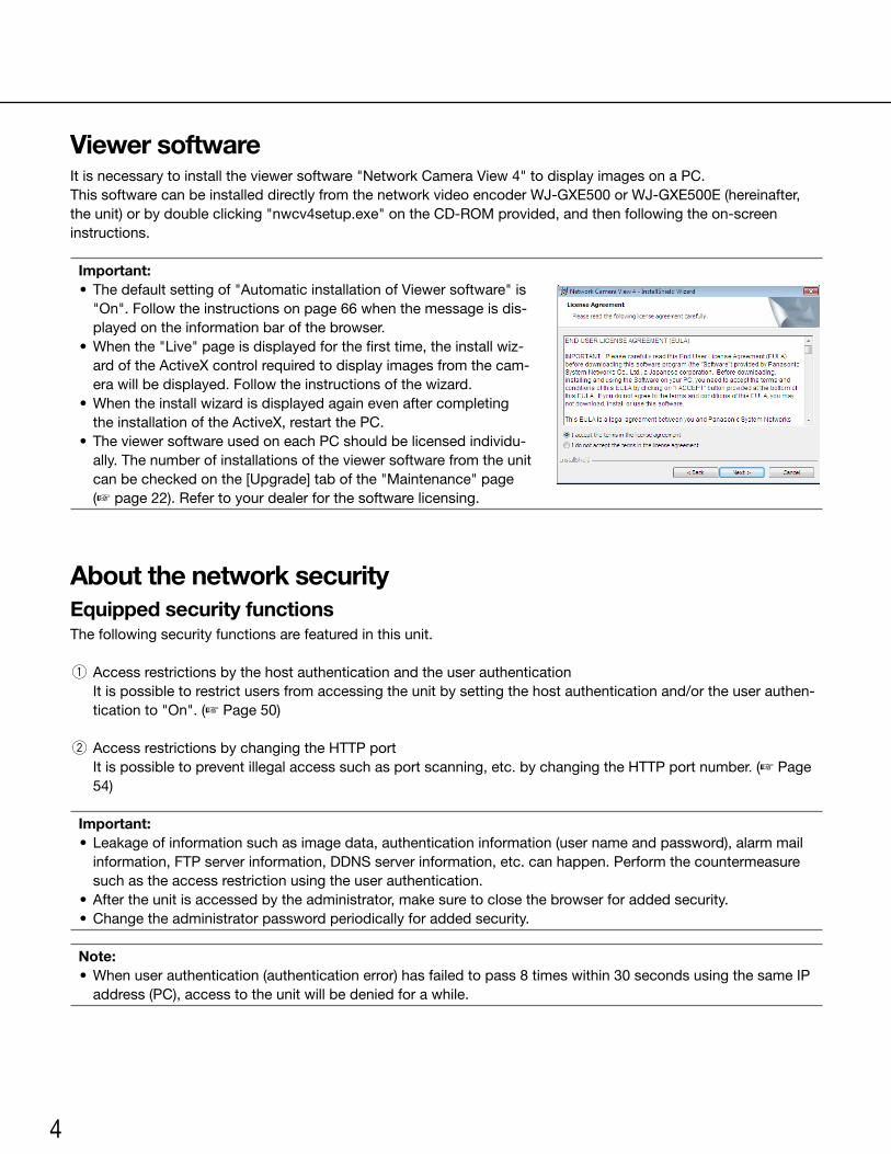
Viewer softwareIt is necessary to install the viewer software "Network Camera View 4" to display images on a PC.This software can be installed directly from the network video encoder WJ-GXE500 or WJ-GXE500E (hereinafter, theunit)orbydoubleclicking"nwcv4setup.exe"ontheCD-ROMprovided,andthenfollowingtheon-screeninstructions.
Important: • Thedefaultsettingof"AutomaticinstallationofViewersoftware"is
"On".Followtheinstructionsonpage66whenthemessageisdis-played on the information bar of the browser.
•Whenthe"Live"pageisdisplayedforthefirsttime,theinstallwiz-ard of the ActiveX control required to display images from the cam-erawillbedisplayed.Followtheinstructionsofthewizard.
•Whentheinstallwizardisdisplayedagainevenaftercompletingthe installation of the ActiveX, restart the PC.
• TheviewersoftwareusedoneachPCshouldbelicensedindividu-ally. The number of installations of the viewer software from the unit can be checked on the [Upgrade] tab of the "Maintenance" page (☞ page 22). Refer to your dealer for the software licensing.
About the network securityEquipped security functionsThe following security functions are featured in this unit.
q Access restrictions by the host authentication and the user authentication It is possible to restrict users from accessing the unit by setting the host authentication and/or the user authen-
ticationto"On".(☞ Page 50)
w Access restrictions by changing the HTTP port It is possible to prevent illegal access such as port scanning, etc. by changing the HTTP port number. (☞ Page
54)
Important: • Leakageofinformationsuchasimagedata,authenticationinformation(usernameandpassword),alarmmail
information, FTP server information, DDNS server information, etc. can happen. Perform the countermeasure such as the access restriction using the user authentication.
•Aftertheunitisaccessedbytheadministrator,makesuretoclosethebrowserforaddedsecurity. •Changetheadministratorpasswordperiodicallyforaddedsecurity.
Note: •Whenuserauthentication(authenticationerror)hasfailedtopass8timeswithin30secondsusingthesameIP
address (PC), access to the unit will be denied for a while.
5
Monitor images on a PCThe following are descriptions of how to monitor images from the camera on a PC.
Monitor images from a single camera
Important: •WhentheHTTPportnumberischangedfrom"80",
enter"http://IPaddressoftheunit+:(colon)+portnumber" in the address box of the browser.
Example:Whentheportnumberissetto"8080" http://192.168.0.11:8080 •Whentheunitisinalocalnetwork,configurethe
proxy server setting of the web browser (under "InternetOptions…"under"Tools"ofthemenubar)to bypass the proxy server for the local address.
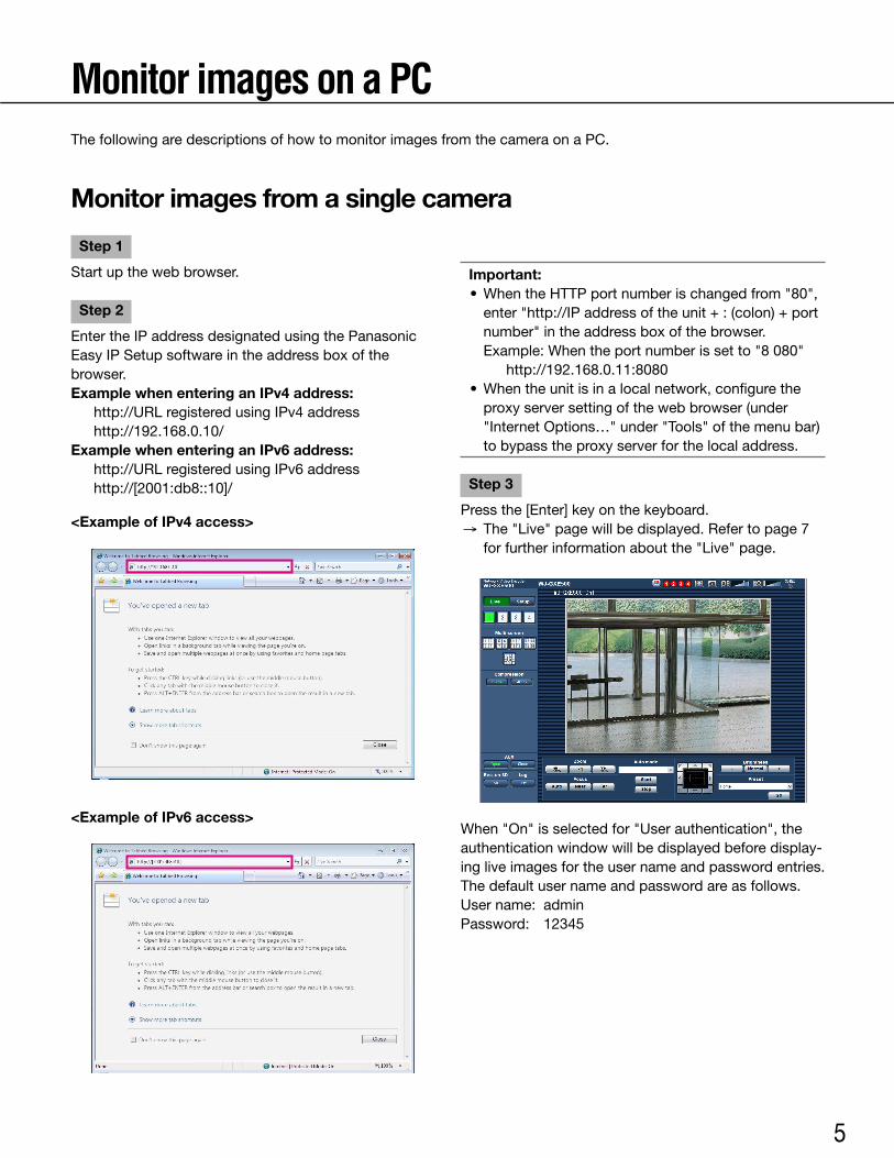
Step 3
Press the [Enter] key on the keyboard. → The "Live" page will be displayed. Refer to page 7
for further information about the "Live" page.
When"On"isselectedfor"Userauthentication",theauthentication window will be displayed before display-ing live images for the user name and password entries.The default user name and password are as follows.Username: adminPassword: 12345
Step 1
Start up the web browser.
Step 2
Enter the IP address designated using the Panasonic Easy IP Setup software in the address box of the browser.Example when entering an IPv4 address: http://URLregisteredusingIPv4address http://192.168.0.10/Example when entering an IPv6 address: http://URLregisteredusingIPv6address http://[2001:db8::10]/
<Example of IPv4 access>
<Example of IPv6 access>
6
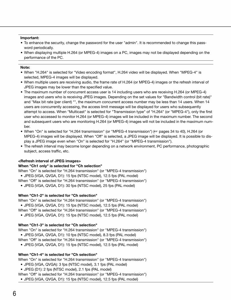
Important: • Toenhancethesecurity,changethepasswordfortheuser"admin".Itisrecommendedtochangethispass-
word periodically. •WhendisplayingmultipleH.264(orMPEG-4)imagesonaPC,imagesmaynotbedisplayeddependingonthe
performance of the PC.
Note: •When"H.264"isselectedfor"Videoencodingformat",H.264videowillbedisplayed.When"MPEG-4"is
selected, MPEG-4 images will be displayed. •Whenmultipleusersarereceivingaudio,theframerateofH.264(orMPEG-4)imagesortherefreshintervalof
JPEG images may be lower than the specified value. • Themaximumnumberofconcurrentaccessuseris14includinguserswhoarereceivingH.264(orMPEG-4)
images and users who is receiving JPEG images. Depending on the set values for "Bandwidth control (bit rate)" and "Max bit rate (per client) *", the maximum concurrent access number may be less than 14 users. When 14 users are concurrently accessing, the access limit message will be displayed for users who subsequently attempt to access. When "Multicast" is selected for "Transmission type" of "H.264" (or "MPEG-4"), only the first user who accessed to monitor H.264 (or MPEG-4) images will be included in the maximum number. The second and subsequent users who are monitoring H.264 (or MPEG-4) images will not be included in the maximum num-ber.
•When"On"isselectedfor"H.264transmission"(or"MPEG-4transmission")(☞ pages 34 to 40), H.264 (or MPEG-4)imageswillbedisplayed.When"Off"isselected,aJPEGimagewillbedisplayed.Itispossibletodis-playaJPEGimageevenwhen"On"isselectedfor"H.264"(or"MPEG-4transmission").
• Therefreshintervalmaybecomelongerdependingonanetworkenvironment,PCperformance,photographicsubject, access traffic, etc.
<Refresh interval of JPEG images>When "Ch1 only" is selected for "Ch selection"When"On"isselectedfor"H.264transmission"(or"MPEG-4transmission") • JPEG(VGA,QVGA,D1):15fps(NTSCmodel),12.5fps(PALmodel)When"Off"isselectedfor"H.264transmission"(or"MPEG-4transmission") • JPEG(VGA,QVGA,D1):30fps(NTSCmodel),25fps(PALmodel)
When "Ch1-2" is selected for "Ch selection"When"On"isselectedfor"H.264transmission"(or"MPEG-4transmission") • JPEG(VGA,QVGA,D1):15fps(NTSCmodel),12.5fps(PALmodel)When"Off"isselectedfor"H.264transmission"(or"MPEG-4transmission") • JPEG(VGA,QVGA,D1):15fps(NTSCmodel),12.5fps(PALmodel)
When "Ch1-3" is selected for "Ch selection"When"On"isselectedfor"H.264transmission"(or"MPEG-4transmission") • JPEG(VGA,QVGA,D1):10fps(NTSCmodel),8.3fps(PALmodel)When"Off"isselectedfor"H.264transmission"(or"MPEG-4transmission") • JPEG(VGA,QVGA,D1):15fps(NTSCmodel),12.5fps(PALmodel)
When "Ch1-4" is selected for "Ch selection"When"On"isselectedfor"H.264transmission"(or"MPEG-4transmission") • JPEG(VGA,QVGA):3fps(NTSCmodel),3.1fps(PALmodel) • JPEG(D1):2fps(NTSCmodel),2.1fps(PALmodel)When"Off"isselectedfor"H.264transmission"(or"MPEG-4transmission") • JPEG(VGA,QVGA,D1):15fps(NTSCmodel),12.5fps(PALmodel)
7
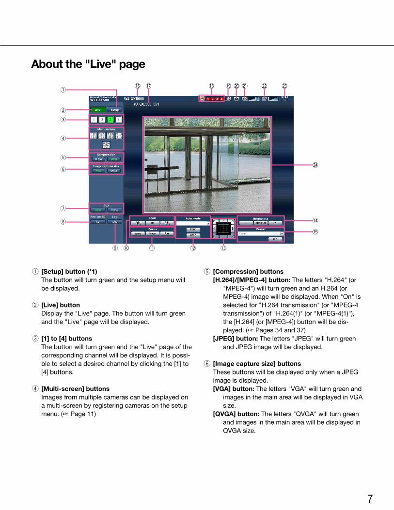
About the "Live" page
q [Setup] button (*1) The button will turn green and the setup menu will
be displayed.
w [Live] button Display the "Live" page. The button will turn green
and the "Live" page will be displayed.
e [1] to [4] buttons The button will turn green and the "Live" page of the
corresponding channel will be displayed. It is possi-ble to select a desired channel by clicking the [1] to [4] buttons.
r [Multi-screen] buttons Images from multiple cameras can be displayed on
a multi-screen by registering cameras on the setup menu. (☞ Page 11)
t [Compression] buttons[H.264]/[MPEG-4] button: The letters "H.264" (or
"MPEG-4") will turn green and an H.264 (or MPEG-4)imagewillbedisplayed.When"On"isselected for "H.264 transmission" (or "MPEG-4 transmission") of "H.264(1)" (or "MPEG-4(1)"), the [H.264] (or [MPEG-4]) button will be dis-played. (☞ Pages 34 and 37)
[JPEG] button: The letters "JPEG" will turn green and JPEG image will be displayed.
y [Image capture size] buttons These buttons will be displayed only when a JPEG
image is displayed.[VGA] button: The letters "VGA" will turn green and
images in the main area will be displayed in VGA size.
[QVGA] button:Theletters"QVGA"willturngreenand images in the main area will be displayed in QVGAsize.
q
w
e
r
t
y
u
i
o !0 !1 !2 !3
!6 !7 !9!8 @0 @1 @2 @3
@4
!4
!5

8
u [AUX] buttons (*2) [AUX] button will become available only when "AUX
output" is selected for "Terminal 3" on the setup menu. (☞ Page 45)[Open] button:Theletters"Open"willturngreen
and the status of AUX connector will be open.[Close] button: The letters "Close" will turn green
and the status of the AUX connector will be closed.
i [Rec. on SD] button (*2) This button will be displayed only when "Manual" is
selected for "Save trigger" on the setup menu. (☞ Page 31)
Click this button to manually record images on the SD memory card. Refer to page 12 for descriptions of how to manually record images on the SD memo-ry card.
o [Log] button (*1) [List]buttonwillbedisplayedonlywhen"On"is
selected for "Save logs" on the setup menu. (☞ page 33) When this button is clicked, the log list will be displayed and images saved on the SD memory card can be played. Refer to pages 17 to 20 for further information about the log list and for how to play images on the SD memory card.
!0 [Zoom] buttons (*2)
:Clickthisbuttontoadjustthezoomratioto the WIDE side.
:Clickthisbuttontosetthezoomratiotox1.
:Clickthisbuttontoadjustthezoomratioto the TELE side.
!1 [Focus] buttons (*2)
:Clickthisbuttontoadjustthefocusauto-matically.
:Clickthisbuttontoadjustthefocustothe"Near" side.
:Clickthisbuttontoadjustthefocustothe"Far" side.
!2 Auto mode (*2) Select an operation from the pull-down menu and
click the [Start] button. The selected operation will start.
Click the [Stop] button to stop the operation. The selected operation will stop when the camera
(panning/tilting/zooming/focusing)isoperated.Auto track: Performs auto track when the camera
supportsautotrack(AUTOTRACK).Auto pan: Automatically pans between the start
position and the end position set in advance. Evenwhenthecameraisoperatedforzooming
or focusing, the camera continues panning.Preset position sequence: Automatically moves to
the preset positions orderly (start from the low-est preset position number).
Patrol 1-4:Operatesthecamerainaccordancewithpatrol function settings.
Note: • Tocheckifthecamerasupportsautotrack,referto
the operating instructions of the camera. • Toactivateautopan,sort,presetpositionsequence
or patrol 1-4, it is required to perform the settings on the setup menu of camera in advance. (☞ Page 41)
•WhileacameracontrolledviatheRS-485communi-cation interface is executing a patrol function, it is impossible to start another one. Stop the current patrol function before starting a new one.
!3 Control pad/buttons (*2)
:Left-clickonthecontrolpadtoadjustthehorizontal/verticalposition of the camera (panning/tilting).
Panning/tilting speed will be faster if a clicked point gets far-
ther from the center point of the control pad. It is also possible to pan/tilt the camera by dragging
the mouse. Zoom and focus can be adjusted by right-clicking. When an upper/lower area of the con-trol pad is right-clicked, the displayed image will be zoomedin/outon.Whenaleft/rightareaisright-clicked, the focus will be adjusted to the Near/Far side.
9
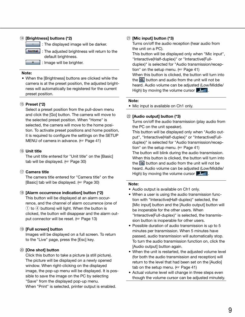
!4 [Brightness] buttons (*2)
:Thedisplayedimagewillbedarker.
:Theadjustedbrightnesswillreturntothedefault brightness.
:Imagewillbebrighter.
Note: •Whenthe[Brightness]buttonsareclickedwhilethe
camera is at the preset position, the adjusted bright-ness will automatically be registered for the current preset position.
!5 Preset (*2) Select a preset position from the pull-down menu
and click the [Go] button. The camera will move to the selected preset position. When "Home" is selected, the camera will move to the home posi-tion. To activate preset positions and home position, it is required to configure the settings on the SETUP MENU of camera in advance. (☞ Page 41)
!6 Unit title The unit title entered for "Unit title" on the [Basic]
tab will be displayed. (☞ Page 30)
!7 Camera title The camera title entered for "Camera title" on the
[Basic] tab will be displayed. (☞ Page 30)
!8 [Alarm occurrence indication] button (*2) This button will be displayed at an alarm occur-
rence, and the channel of alarm occurrence (one of q to r buttons) will light. When the button is clicked, the button will disappear and the alarm out-put connector will be reset. (☞ Page 13)
!9 [Full screen] button Images will be displayed on a full screen. To return
to the "Live" page, press the [Esc] key.
@0 [One shot] button Click this button to take a picture (a still picture).
The picture will be displayed on a newly opened window. When right-clicking on the displayed image, the pop-up menu will be displayed. It is pos-sible to save the image on the PC by selecting "Save" from the displayed pop-up menu.
When "Print" is selected, printer output is enabled.
@1 [Mic input] button (*3) Turns on/off the audio reception (hear audio from
the unit on a PC). This button will be displayed only when "Mic input",
"Interactive(Half-duplex)" or "Interactive(Full-duplex)" is selected for "Audio transmission/recep-tion" on the setup menu. (☞ Page 41)
When this button is clicked, the button will turn into the button and audio from the unit will not be heard. Audio volume can be adjusted (Low/Middle/High) by moving the volume cursor .
Note: •MicinputisavailableonCh1only. @2 [Audio output] button (*3) Turns on/off the audio transmission (play audio from
the PC on the unit speaker). This button will be displayed only when "Audio out-
put", "Interactive(Half-duplex)" or "Interactive(Full-duplex)" is selected for "Audio transmission/recep-tion" on the setup menu. (☞ Page 41)
The button will blink during the audio transmission. When this button is clicked, the button will turn into
the button and audio from the unit will not be heard. Audio volume can be adjusted (Low/Middle/High) by moving the volume cursor .
Note: •AudiooutputisavailableonCh1only. •Whenauserisusingtheaudiotransmissionfunc-
tion with "Interactive(Half-duplex)" selected, the [Mic input] button and the [Audio output] button will be inoperable for the other users. When "Interactive(Full-duplex)" is selected, the transmis-sion button is inoperable for other users.
•Possibledurationofaudiotransmissionisupto5minutes per transmission. When 5 minutes have passed, audio transmission will automatically stop. To turn the audio transmission function on, click the [Audio output] button again.
•Whentheunitisrestarted,theadjustedvolumelevel(for both the audio transmission and reception) will return to the level that had been set on the [Audio] tab on the setup menu. (☞ Page 41)
•Actualvolumelevelwillchangeinthreestepseventhough the volume cursor can be adjusted minutely.
10
@3 SD recording status indicator The status of the SD recording can be checked with
this indicator. When the SD recording starts, this indicator will light
red. When the SD recording stops, this indicator will go off.
This indicator will be displayed only when "Manual" is selected for "Save trigger" on the setup menu. (☞ Page 31)
@4 Main area Images from the camera will be displayed in this
area. The current time and date will be displayed accord-
ing to the settings configured for "Time display for-mat" and "Date/time display format". (☞ Page 30)
Click a desired point in the main area on the "Live" page that is to be the center of the angle of view. The camera moves to adjust the position in order to set the clicked point as the center.
*1Onlyoperablebyuserswhoseaccesslevelis"1.Administrator"
*2Onlyoperablebyuserswhoseaccesslevelis"1.Administrator"or"2.Cameracontrol"when"On"isselected for "User auth." (☞ page 50).
*3Operablebyuserswhobelongtotheaccesslevelselected for "Permission level of audio trans./recep." on the [Audio] tab of the "Image/Audio" page. Refer to page 50 for further information about the access level.
Note: •Whenoperatedbyaloweraccessleveluser,images
displayed on the screen may be changed temporari-ly. This does not affect operation of the camera.
11
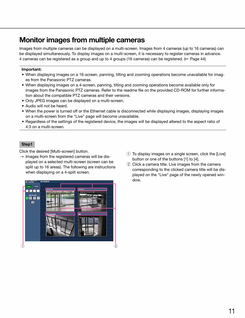
Monitor images from multiple camerasImages from multiple cameras can be displayed on a multi-screen. Images from 4 cameras (up to 16 cameras) can be displayed simultaneously. To display images on a multi-screen, it is necessary to register cameras in advance.4 cameras can be registered as a group and up to 4 groups (16 cameras) can be registered. (☞ Page 44)
Important: •Whendisplayingimagesona16-screen,panning,tiltingandzoomingoperationsbecomeunavailableforimag-
es from the Panasonic PTZ cameras. •Whendisplayingimagesona4-screen,panning,tiltingandzoomingoperationsbecomeavailableonlyfor
imagesfromthePanasonicPTZcameras.RefertothereadmefileontheprovidedCD-ROMforfurtherinforma-tion about the compatible PTZ cameras and their versions.
•OnlyJPEGimagescanbedisplayedonamulti-screen. •Audiowillnotbeheard. •WhenthepoweristurnedoffortheEthernetcableisdisconnectedwhiledisplayingimages,displayingimages
on a multi-screen from the "Live" page will become unavailable. •Regardlessofthesettingsoftheregistereddevice,theimageswillbedisplayedalteredtotheaspectratioof
4:3onamulti-screen.
Step1
Click the desired [Multi-screen] button. → Images from the registered cameras will be dis-
played on a selected multi-screen (screen can be split up to 16 areas). The following are instructions when displaying on a 4-split screen.
q To display images on a single screen, click the [Live] button or one of the buttons [1] to [4].
w Click a camera title. Live images from the camera corresponding to the clicked camera title will be dis-played on the "Live" page of the newly opened win-dow.
q w
12
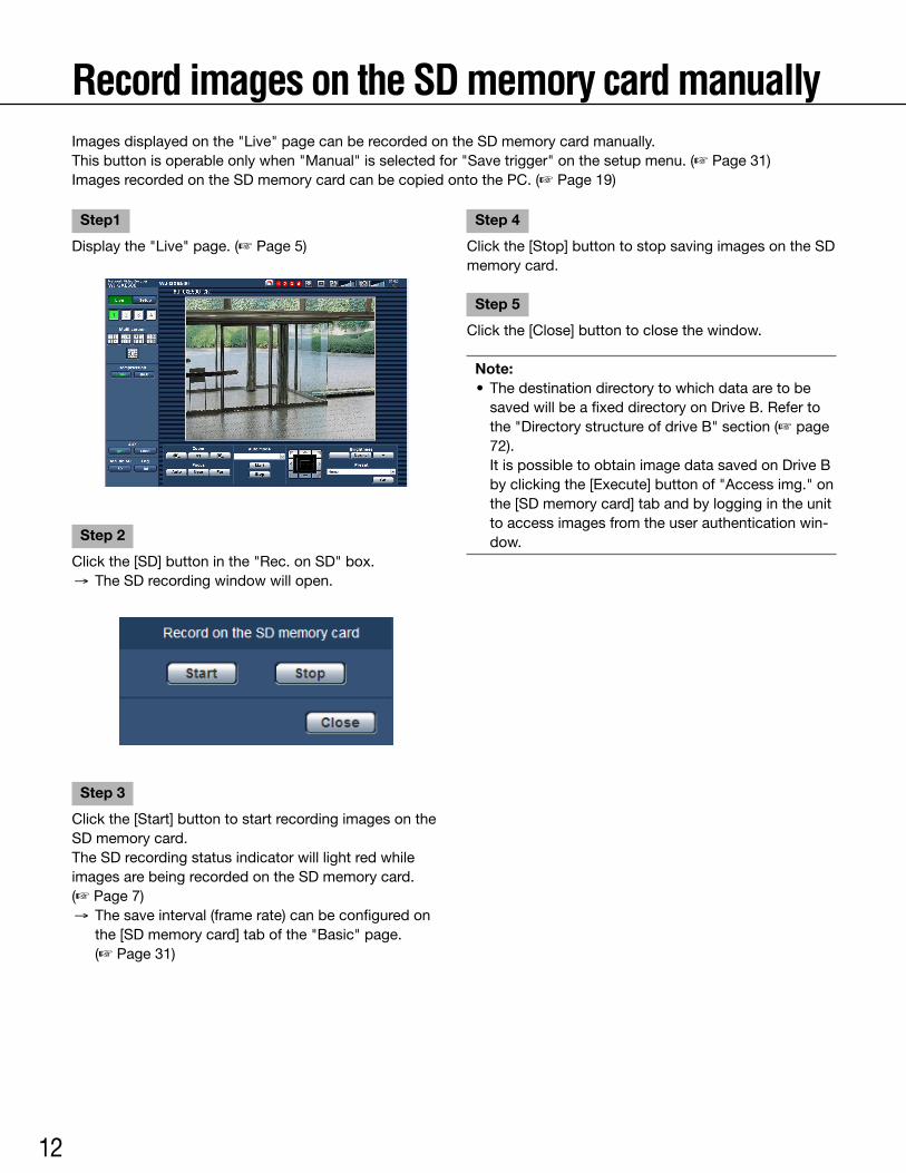
Record images on the SD memory card manuallyImages displayed on the "Live" page can be recorded on the SD memory card manually.This button is operable only when "Manual" is selected for "Save trigger" on the setup menu. (☞ Page 31)Images recorded on the SD memory card can be copied onto the PC. (☞ Page 19)
Step1
Display the "Live" page. (☞ Page 5)
Step 2
Click the [SD] button in the "Rec. on SD" box. → The SD recording window will open.
Step 3
Click the [Start] button to start recording images on the SD memory card. The SD recording status indicator will light red while images are being recorded on the SD memory card. (☞ Page 7) → The save interval (frame rate) can be configured on
the [SD memory card] tab of the "Basic" page. (☞ Page 31)
Step 4
Click the [Stop] button to stop saving images on the SD memory card.
Step 5
Click the [Close] button to close the window.
Note: • Thedestinationdirectorytowhichdataaretobe
saved will be a fixed directory on Drive B. Refer to the "Directory structure of drive B" section (☞ page 72).
It is possible to obtain image data saved on Drive B by clicking the [Execute] button of "Access img." on the [SD memory card] tab and by logging in the unit to access images from the user authentication win-dow.

13
Action at an alarm occurrenceThe alarm action (action at an alarm occurrence) will be performed when the following alarms occur.
Alarm typeTerminal alarm:WhenconnectinganalarmdevicesuchasasensortotheEXTI/Oterminalsoftheunit,thealarm
action will be performed when the connected alarm device is activated. (☞ Page 45)VMD alarm: When motion is detected in the set VMD area, the alarm action will be performed. (☞ Page 45)
* VMD stands for "Video Motion Detection".Command alarm: When a Panasonic alarm protocol is received from the connected device via a network, the
alarm action will be performed. (☞ Page 45)Camera site alarm: When a camera connected to a Video input connector detects an alarm by alarm sensors or
cameras' motion detectors, etc., and the unit receives the alarm input signal from the camera, the alarm action will be performed. (☞ Page 45)
Video loss: When the loss of video input signals is detected due to coaxial cable disconnections or camera trou-bles, the alarm action will be performed. (☞ Page 45)
Action at an alarm occurrence •Displaythe[Alarmoccurrenceindication]buttononthe"Live"page.(☞ Page 7) The alarm occurrence indication button will be displayed on the "Live" page at an alarm occurrence.
Important: •When"Polling(30sec)"isselectedfor"Alarmstatusupdatemode"(☞ page 30), the [Alarm occurrence indica-
tion] button will be refreshed in 30-second intervals. For this reason, it may take a maximum of 30 seconds until the [Alarm occurrence indication] button is displayed on the "Live" page at an alarm occurrence.
•Notifyofalarmoccurrencestothedeviceconnectedtothealarmconnector Itispossibletooutputsignalsfromthealarmconnectorontherearoftheunitandsoundthebuzzerwhenan
alarm occurs. The settings for the alarm output can be configured on the [Alarm] tab of the "Alarm" page. (☞ Page 45)
•SaveimagesontheSDmemorycard When an alarm occurs, images will be saved on the SD memory card. The settings to save images on the SD
memory card can be configured on the [SD memory card] tab of the "Basic" page. (☞ Page 31)
• Transmitanimageontoaserverautomatically An alarm image can be transmitted at an alarm occurrence to the server designated in advance. The settings
required to transmit an alarm image to a server can be configured on the [Alarm] tab of the "Alarm" page and the [FTP] tab of the "Server" page (☞ pages 45 and 52).
Important: •Select"FTPerror"for"Savetrigger"onthe[SDmemorycard]tabwhenusingtheSDmemorycard.When
"Alarm input" or "Manual" is selected for "Save trigger", an alarm image will not be transmitted at an alarm occurrence to the FTP server. (☞ Page 31)
14
•Notifyofalarmoccurrencesbye-mail Alarm mail (alarm occurrence notification) can be sent at an alarm occurrence to the e-mail addresses registered
in advance. The settings for alarm mail can be configured in the "Mail notification" section of the [Notification] tab of the
"Alarm" page and the [Mail] tab of the "Server" page (☞ pages 48 and 52).
•NotifyofalarmoccurrencestothedesignatedIPaddresses(Panasonicalarmprotocolnotification) This function is available only when a Panasonic device, such as the network disk recorder, is connected to the
system.When"On"isselectedfor"Panasonicalarmprotocolnotification",theconnectedPanasonicdevicewillbe notified that the unit is in the alarm state. The settings for Panasonic alarm protocol can be configured in the Panasonic alarm protocol section of the [Notification] tab of the "Alarm" page. (☞ Page 48)

15
Transmit images onto an FTP serverImages can be transmitted to an FTP server. By configuring the following settings, transmission of images captured at an alarm occurrence or captured at a designated interval to an FTP server will become available.
Important: •Whenusingthisfunction,settheusernameandthepasswordtoaccesstheFTPservertorestrictuserswho
can log into the FTP server. • TotransmitimagestotheFTPserver,select"Notuse"for"SDmemorycard",orselect"FTPerror"for"Save
trigger" on the [SD memory card] tab of the "Basic" page. (☞ Page 31)
Transmit an alarm image at an alarm occurrence (Alarm image transmission)An alarm image can be transmitted at an alarm occurrence to the FTP server. To transmit alarm images to an FTP server, it is necessary to configure the settings in advance.The settings for the FTP server can be configured on the [FTP] tab of the "Server" page. (☞ Page 52)The alarm image transmission function can be turned on/off on the [Alarm] tab of the "Alarm" page. (☞ Page 45)
Note: •Dependingonthenetworktraffic,thenumberofthetransmittedimagesmaynotreachthesetnumberofimages
to be transmitted. •AlarmimagesfailedtobetransmittedtotheFTPserveratanalarmoccurrencewillnotbesavedontheSD
memory card.
Transmit images at a designated interval or period (FTP periodic image trans-mission)Images can be transmitted at a designated interval or period. To transmit images at a designated interval or period, it is necessary to configure the settings in advance.The settings for the FTP server can be configured on the [FTP] tab of the "Server" page. (☞ Page 52)It is possible to determine whether or not to use the FTP periodic image transmission function and to configure the settings relating to alarm images and the schedule on the [FTP img. trans.] tab of the "Network" page. (☞ Page 56)
Note: •Dependingonthelinespeedorthetraffic,imagesmaynotbetransmittedatthedesignatedinterval. •When"On"isselectedforboththealarmimagetransmissionfunctionandtheFTPperiodicimagetransmission
function, the alarm image transmission function will be given priority over the FTP periodic image transmission function. Therefore, images may not be transmitted at the interval designated on the "FTP periodic image trans-mission" setting.
16
Save images on the SD memory card when images have failed to be transmit-ted using the FTP periodic image transmission functionImages that have failed to be transmitted using the FTP periodic image transmission can be saved automatically on the SD memory card. Images saved on the SD memory card can be obtained from the [SD memory card] tab of the "Basic" page. (☞ Page 31)TousetheSDmemoryrecordingfunctionfeaturedinPanasonic’snetworkdiskrecorder,select"Off"for"FTPperi-odic image transmission" (☞ page 56) and "FTP error" for "Save trigger" (☞ page 31).We make no guarantee for any damages of files on the SD memory card incurred by malfunction or error occur-rence in files saved in the SD memory card regardless of what the cause may be.
Note: •Dependingonthesettingsandstatusofuse,notallimagesfailedintheFTPperiodictransmissionmaynotbe
saved on the SD memory card.
17
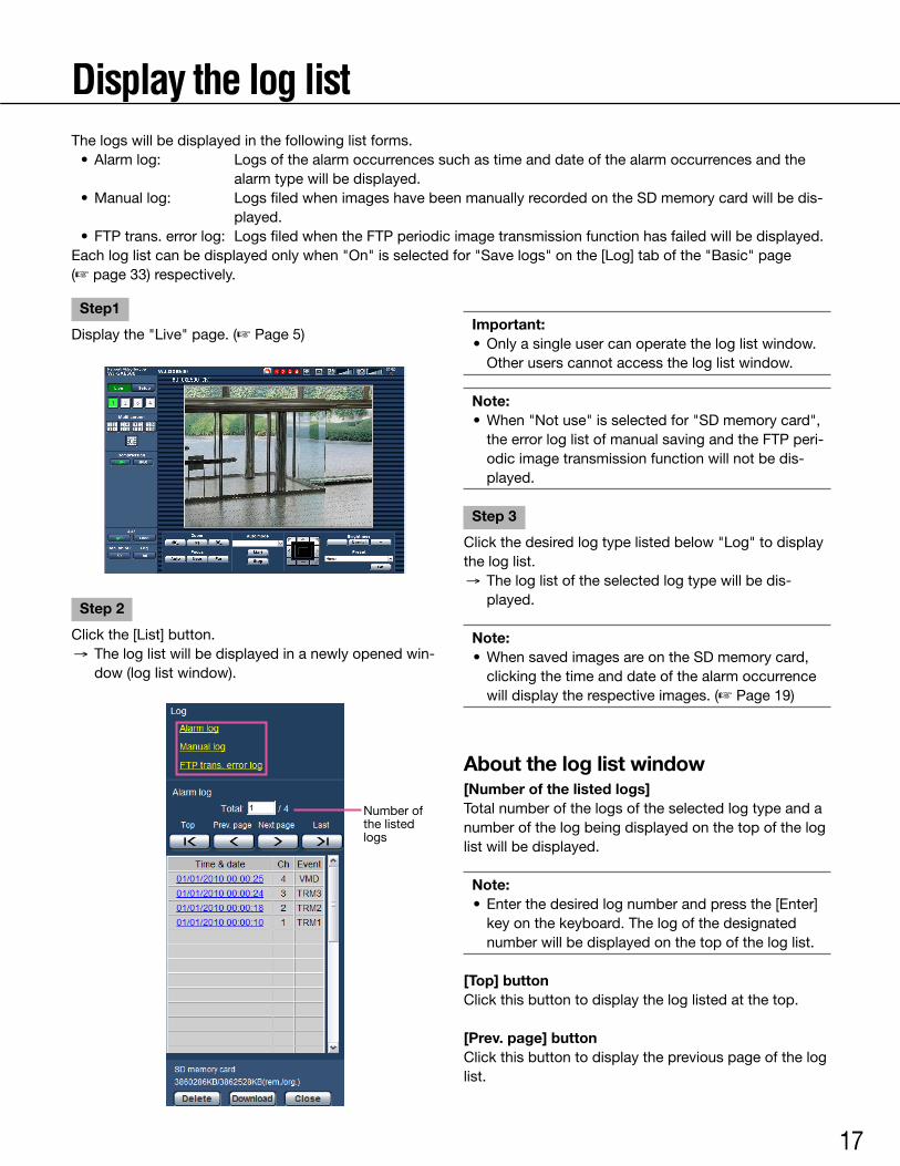
Display the log listThe logs will be displayed in the following list forms. •Alarmlog: Logsofthealarmoccurrencessuchastimeanddateofthealarmoccurrencesandthe
alarm type will be displayed. •Manuallog: LogsfiledwhenimageshavebeenmanuallyrecordedontheSDmemorycardwillbedis-
played. • FTPtrans.errorlog: LogsfiledwhentheFTPperiodicimagetransmissionfunctionhasfailedwillbedisplayed.Eachloglistcanbedisplayedonlywhen"On"isselectedfor"Savelogs"onthe[Log]tabofthe"Basic"page (☞ page 33) respectively.
Step1
Display the "Live" page. (☞ Page 5)
Step 2
Click the [List] button. → The log list will be displayed in a newly opened win-
dow (log list window).
Important: •Onlyasingleusercanoperatetheloglistwindow.
Otheruserscannotaccesstheloglistwindow.
Note: •When"Notuse"isselectedfor"SDmemorycard",
the error log list of manual saving and the FTP peri-odic image transmission function will not be dis-played.
Step 3
Click the desired log type listed below "Log" to display the log list. → The log list of the selected log type will be dis-
played.
Note: •WhensavedimagesareontheSDmemorycard,
clicking the time and date of the alarm occurrence will display the respective images. (☞ Page 19)
About the log list window[Number of the listed logs]Total number of the logs of the selected log type and a number of the log being displayed on the top of the log list will be displayed.
Note: • Enterthedesiredlognumberandpressthe[Enter]
key on the keyboard. The log of the designated number will be displayed on the top of the log list.
[Top] buttonClick this button to display the log listed at the top.
[Prev. page] buttonClick this button to display the previous page of the log list.
Number of the listed logs
18
Note: •Whenthemousebuttonishelddownwhileplacing
the mouse pointer on the [Prev. page] button, the displayed log number will be decremented.
When the mouse button is released, the decrement of the log number will stop and the log number dis-played at the moment when the mouse button is released will be the top of the currently displayed page.
[Next page] buttonClick this button to display the next page of the log list.
Note: •Whenthemousebuttonishelddownwhileplacing
the mouse pointer on the [Next page] button, the displayed log number will be incremented.
When the mouse button is released, the decrement of the log number will stop and the log number dis-played at the moment when the mouse button is released will be the top of the currently displayed page.
[Last] buttonClick this button to display the log listed at the bottom.
[Time & date]Time and date when each log has been filed will be dis-played.
Note: •When"Off"isselectedfor"Timedisplayformat"(☞
page 30), time and date of alarm occurrence will be displayed in 24-hour format.
• Therecordingtimingoflogsareasfollows.Alarm log: Alarm occurrence time and date will be
filed as a log.Manual log: Time and date when recording of
images onto the SD memory card started will be filed as a log. When recording are performed sequentially, logs will be filed every one hour.
FTP trans. error log: Logs will be filed every one hour.
[Ch]The channel will be displayed.
[Event]The event type will be displayed.The event types will be displayed only when displaying the alarm log list.
TRM1: Alarm by alarm input to Terminal 1TRM2: Alarm by alarm input to Terminal 2TRM3: Alarm by alarm input to Terminal 3VMD: Alarm by VMD alarmCOM: Alarm by command alarmCAM: Alarm by camera site alarmLOSS: Alarm at a video loss occurrence
[SD memory card]Available capacity and the original capacity of the SD memory card will be displayed.The displayed descriptions are the same descriptions displayed as "Remaining capacity" on the [SD memory card] tab. (☞ Page 31)
[Delete] buttonClick this button to delete the currently displayed log list.When using the SD memory card, images associated with the log list will also be deleted.
Important: •WhenmanyimagesaresavedontheSDmemory
card, it will take some time to complete the deletion. • Intheprocessofthedeletion,onlylogswillbe
saved, and it is impossible to save images newly. •Donotturnoffthepoweroftheunituntilthedele-
tion is complete. When the power of the unit is turned off in the pro-
cess of the deletion, some images may remain on the SD memory card.
In this case, click the [Delete] button on the same log list window used to delete the logs.
[Download] buttonClick this button to download all logs of the selected log list as a file onto the PC.
[Close] buttonClick this button to close the log list window.
19
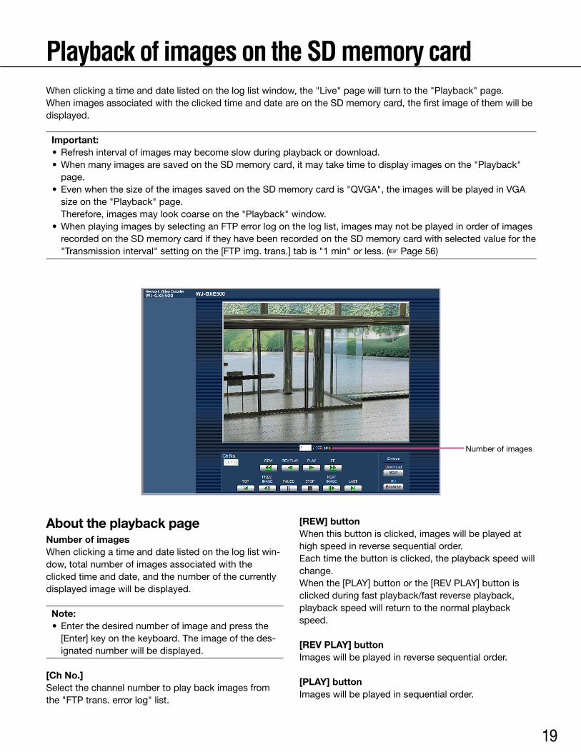
Playback of images on the SD memory cardWhen clicking a time and date listed on the log list window, the "Live" page will turn to the "Playback" page.When images associated with the clicked time and date are on the SD memory card, the first image of them will be displayed.
Important: •Refreshintervalofimagesmaybecomeslowduringplaybackordownload. •WhenmanyimagesaresavedontheSDmemorycard,itmaytaketimetodisplayimagesonthe"Playback"
page. • EvenwhenthesizeoftheimagessavedontheSDmemorycardis"QVGA",theimageswillbeplayedinVGA
sizeonthe"Playback"page. Therefore, images may look coarse on the "Playback" window. •WhenplayingimagesbyselectinganFTPerrorlogontheloglist,imagesmaynotbeplayedinorderofimages
recorded on the SD memory card if they have been recorded on the SD memory card with selected value for the "Transmission interval" setting on the [FTP img. trans.] tab is "1 min" or less. (☞ Page 56)
About the playback pageNumber of imagesWhen clicking a time and date listed on the log list win-dow, total number of images associated with the clicked time and date, and the number of the currently displayed image will be displayed.
Note: • Enterthedesirednumberofimageandpressthe
[Enter] key on the keyboard. The image of the des-ignated number will be displayed.
[Ch No.]Select the channel number to play back images from the "FTP trans. error log" list.
[REW] buttonWhen this button is clicked, images will be played at high speed in reverse sequential order.Each time the button is clicked, the playback speed will change.When the [PLAY] button or the [REV PLAY] button is clicked during fast playback/fast reverse playback, playback speed will return to the normal playback speed.
[REV PLAY] buttonImages will be played in reverse sequential order.
[PLAY] buttonImages will be played in sequential order.
Number of images
20
[FF] buttonWhen this button is clicked, images will be played at high speed in sequential order.Each time the button is clicked, the playback speed will change.When the [PLAY] button or the [REV PLAY] button is clicked during fast playback/fast reverse playback, playback speed will return to the normal playback speed.
[TOP] buttonThe first image will be displayed.
[PREV. IMAGE] buttonThe previous frame will be displayed and paused when this button is clicked during playback.Each time this button is clicked during pausing, the frame previous to the currently displayed frame will be displayed.
Note: •Whenthemousebuttonisbeingheldwhileplacing
the mouse pointer on this button, the displayed image number will be decremented.
When the mouse button is released, the decrement-ing of the image number will stop and the image corresponding to the currently displayed number will be displayed.
[PAUSE] buttonPlayback will be paused when this button is clicked during playback. Playback will resume when this button is clicked during pausing.
[STOP] buttonPlayback will stop and the "Playback" window will turn to the "Live" page.
[NEXT IMAGE] buttonThe next frame will be displayed and paused when this button is clicked during playback.Each time this button is clicked during pausing, the frame next to the currently displayed frame will be dis-played.
Note: •Whenthemousebuttonishelddownwhilethe
mouse pointer is on this button, the image number will be incremented.
When the mouse button is released, the increment of the image number will stop and the image num-ber displayed at the moment when the mouse but-ton is released will be displayed.
[LAST] buttonThe last image will be displayed.
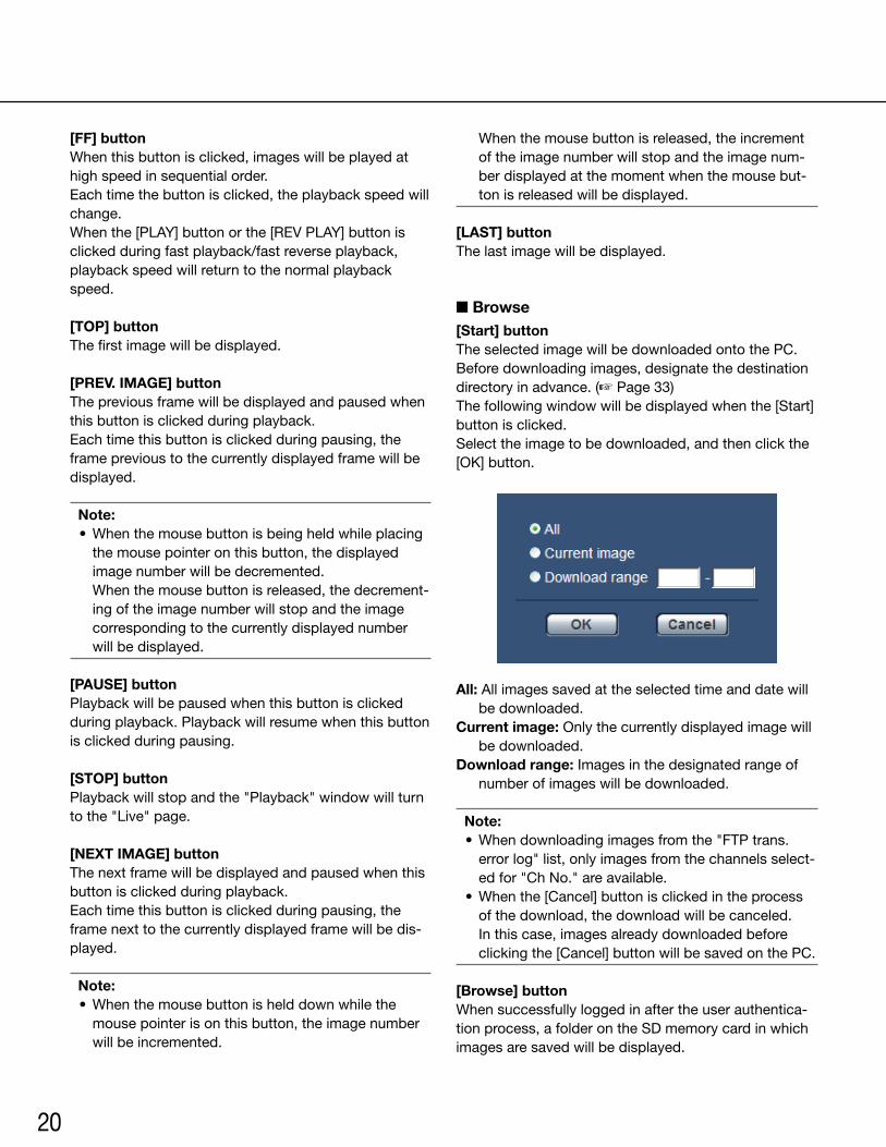
■ Browse[Start] buttonThe selected image will be downloaded onto the PC.Before downloading images, designate the destination directory in advance. (☞ Page 33)The following window will be displayed when the [Start] button is clicked.Select the image to be downloaded, and then click the [OK]button.
All: All images saved at the selected time and date will be downloaded.
Current image:Onlythecurrentlydisplayedimagewillbe downloaded.
Download range: Images in the designated range of number of images will be downloaded.
Note: •Whendownloadingimagesfromthe"FTPtrans.
error log" list, only images from the channels select-ed for "Ch No." are available.
•Whenthe[Cancel]buttonisclickedintheprocessof the download, the download will be canceled.
In this case, images already downloaded before clicking the [Cancel] button will be saved on the PC.
[Browse] buttonWhen successfully logged in after the user authentica-tion process, a folder on the SD memory card in which images are saved will be displayed.

21
Maintenance of the unit [Maintenance]Check the system log [System log]It is possible to check the system log on the [System log] tab of the "Maintenance" page on the setup menu.Up to 4 000 system logs can be saved on the SD memory card when the SD memory card is inserted after select-ing "Use" for "SD memory card" on the [SD memory card] tab (☞ page 31).When "Not use" is selected for "SD memory card", up to 100 system logs can be saved on the built-in memory of the unit.When the saved system logs have reached the maximum number, the newer logs will overwrite the older system logs. In this case, the oldest log is the first to be overwritten.The system logs will be displayed in group of 100 logs each.When using the SD memory card, the logs will be saved even when the power of this unit is turned off. When not using the SD memory card, the logs will be deleted when the power of this unit is turned off.
[Next 100 >>]When clicking "Next 100 >>", the next 100 system logs will be displayed.
[<< Previous 100]When clicking "<< Previous 100", the previous 100 sys-tem logs will be displayed.
[No.]The serial number of the system log will be displayed.
[Time & date]Time and date at the error occurrence will be displayed.
Note: •When"Off"isselectedfor"Timedisplayformat"on
the [Basic] tab (☞ page 30), time & date of logs will be displayed in 24-hour format.
[Error description]The descriptions about the error will be displayed.Refer to page 58 for further information about the sys-tem logs.

22
Upgrade the firmware [Upgrade]It is possible to upgrade firmware on the [Upgrade] tab of the "Maintenance" page on the setup menu. The current firmware of this unit can be checked and upgraded to the latest version on this page.Contact the dealer for further information about the firmware upgrade.
[Model no.], [MAC address], [Serial no.], [Firmware version], [IPL version], [HTML version], [IP address(IPv6)], [Viewer software installation counter]Information of each item will be displayed.
Step1
Contact the dealer and download the latest firmware onto a PC.
Important: •Ablank(space)cannotbeusedforthenameofthe
directory where the downloaded firmware to be saved.
Step 2
Click the [Browse...] button and designate the down-loaded firmware.
Step 3
Click the radio button respective to the desired option todeterminewhetherornottoinitializethesettingsafter completing the firmware upgrade.
Note: •Refertothereadmefileprovidedwiththefirmware
firstanddeterminewhetherornottoinitializethesettings after the firmware upgrade.
Step 4
Click the [Execute] button. → The confirmation window will be displayed. When
"Do not reset the settings to the default after the upgrade." is selected, the confirmation window will not be displayed.
Important: •Beforestartingtheupgrade,select"Off"for"FTP
periodic image transmission" on the [FTP img. trans.] tab of the "Network" page. (☞ Page 56)
•Aftercompletingtheupgrade,besuretodeletetemporary internet files. (☞ Page 64)
•UpgradethefirmwareusingaPCinthesamesub-net as the unit.
• Followtheinstructionsfromthedealerwhenupgrading the firmware.
•Usethedesignatedfile(extension:img)forthefirm-ware upgrade.
• Thenameofthefirmwaretobeusedfortheupgrade should be "gxe500_xxxxx.img".
* ("xxxxx" indicates the version of the firmware.) •Donotturnoffthepoweroftheunitduringthe
upgrade process. •Donotperformanyoperationduringupgradingand
wait until it completes. • Thefollowingnetworksettingswillnotbereset
when upgrading the firmware after selecting "Reset the settings to the default after completing the upgrade. (Except the network settings)".
On/OffforDHCP,IPaddress,subnetmask,defaultgateway, HTTP port, line speed, bandwidth control (bit rate), time & date
• TheviewersoftwareusedoneachPCshouldbelicensed individually. Refer to your dealer for the software licensing.
23
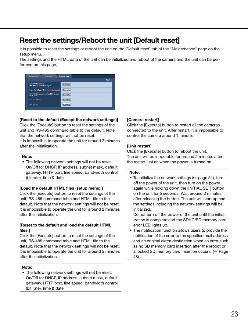
Reset the settings/Reboot the unit [Default reset]It is possible to reset the settings or reboot the unit on the [Default reset] tab of the "Maintenance" page on the setup menu.ThesettingsandtheHTMLdataoftheunitcanbeinitializedandrebootofthecameraandtheunitcanbeper-formed on this page.
[Reset to the default (Except the network settings)]Click the [Execute] button to reset the settings of the unit and RS-485 command table to the default. Note that the network settings will not be reset.It is impossible to operate the unit for around 2 minutes aftertheinitialization.
Note: • Thefollowingnetworksettingswillnotbereset. On/OffforDHCP,IPaddress,subnetmask,default
gateway, HTTP port, line speed, bandwidth control (bit rate), time & date
[Load the default HTML files (setup menu).]Click the [Execute] button to reset the settings of the unit, RS-485 command table and HTML file to the default. Note that the network settings will not be reset.It is impossible to operate the unit for around 2 minutes aftertheinitialization.
[Reset to the default and load the default HTML files.]Click the [Execute] button to reset the settings of the unit, RS-485 command table and HTML file to the default. Note that the network settings will not be reset.It is impossible to operate the unit for around 5 minutes aftertheinitialization.
Note: • Thefollowingnetworksettingswillnotbereset. On/OffforDHCP,IPaddress,subnetmask,default
gateway, HTTP port, line speed, bandwidth control (bit rate), time & date
[Camera restart]Click the [Execute] button to restart all the cameras connected to the unit. After restart, it is impossible to control the camera around 1 minute.
[Unit restart]Click the [Execute] button to reboot the unit.The unit will be inoperable for around 2 minutes after the restart just as when the power is turned on.
Note: • Toinitializethenetworksettings(☞ page 54), turn
off the power of the unit, then turn on the power again while holding down the [INITIAL SET] button on the unit for 5 seconds. Wait around 2 minutes after releasing the button. The unit will start up and the settings including the network settings will be initialized.
Do not turn off the power of the unit until the initial-izationiscompleteandtheSDHC/SDmemorycarderror LED lights up.
• Thenotificationfunctionallowsuserstoprovidethenotification of the error to the specified mail address and an original alarm destination when an error such as no SD memory card insertion after the reboot or a locked SD memory card insertion occurs. (☞ Page 48)
24
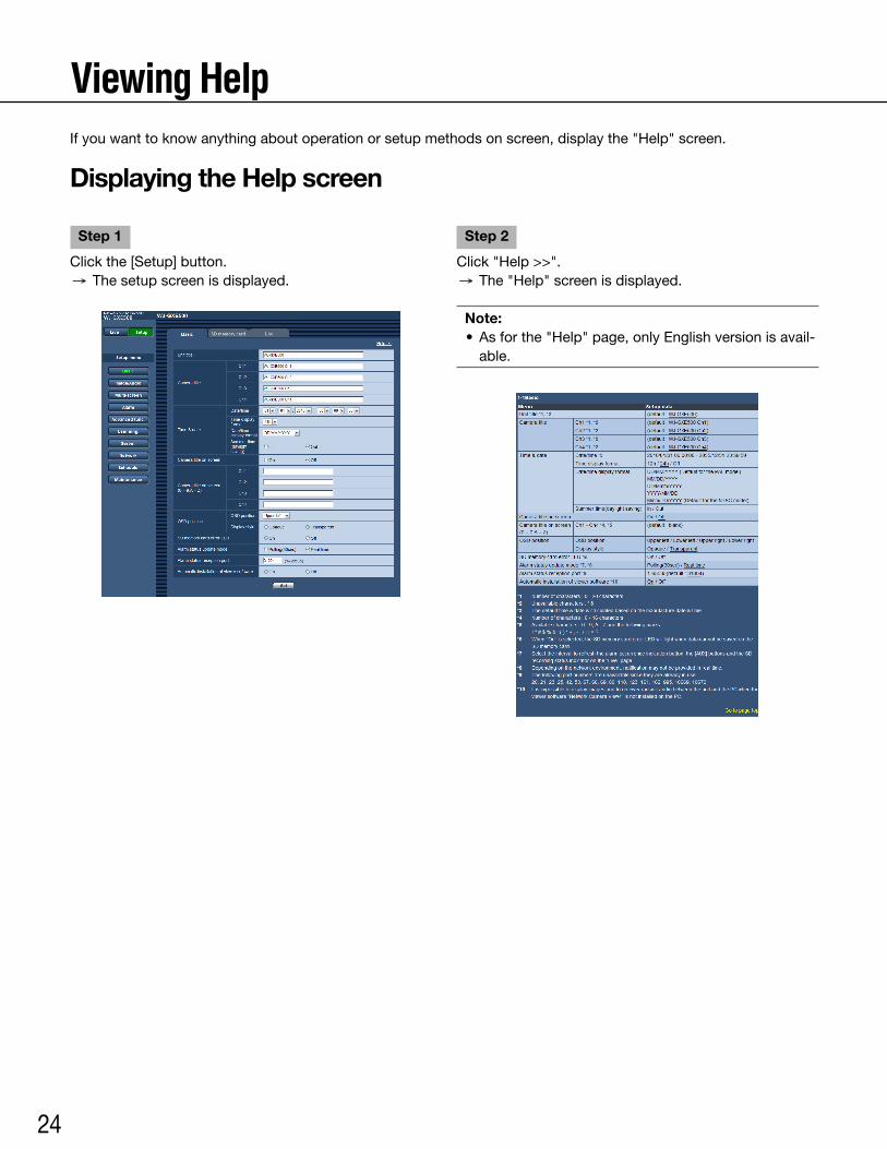
Viewing HelpIf you want to know anything about operation or setup methods on screen, display the "Help" screen.
Displaying the Help screen
Step 1
Click the [Setup] button. → The setup screen is displayed.
Step 2
Click "Help >>". → The "Help" screen is displayed.
Note: •Asforthe"Help"page,onlyEnglishversionisavail-
able.
25
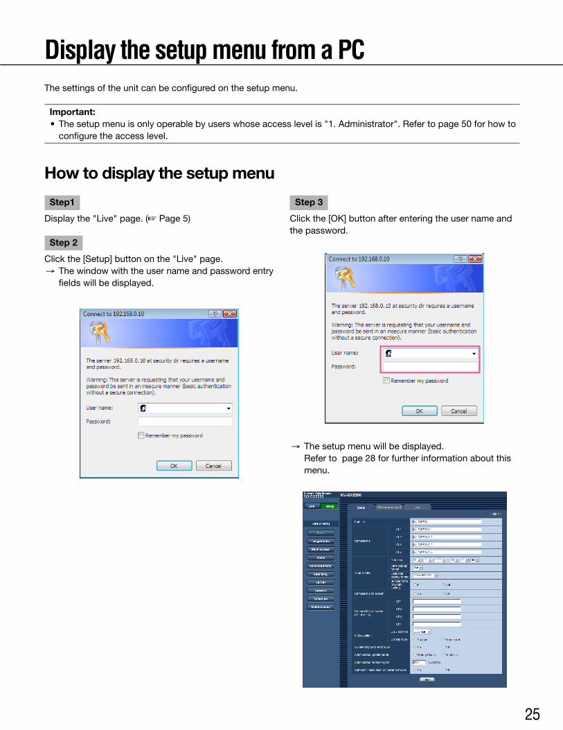
Display the setup menu from a PCThe settings of the unit can be configured on the setup menu.
Important: • Thesetupmenuisonlyoperablebyuserswhoseaccesslevelis"1.Administrator".Refertopage50forhowto
configure the access level.
How to display the setup menu
Step1
Display the "Live" page. (☞ Page 5)
Step 2
Click the [Setup] button on the "Live" page. → The window with the user name and password entry
fields will be displayed.
Step 3
Clickthe[OK]buttonafterenteringtheusernameandthe password.
→ The setup menu will be displayed. Refer to page 28 for further information about this
menu.
26
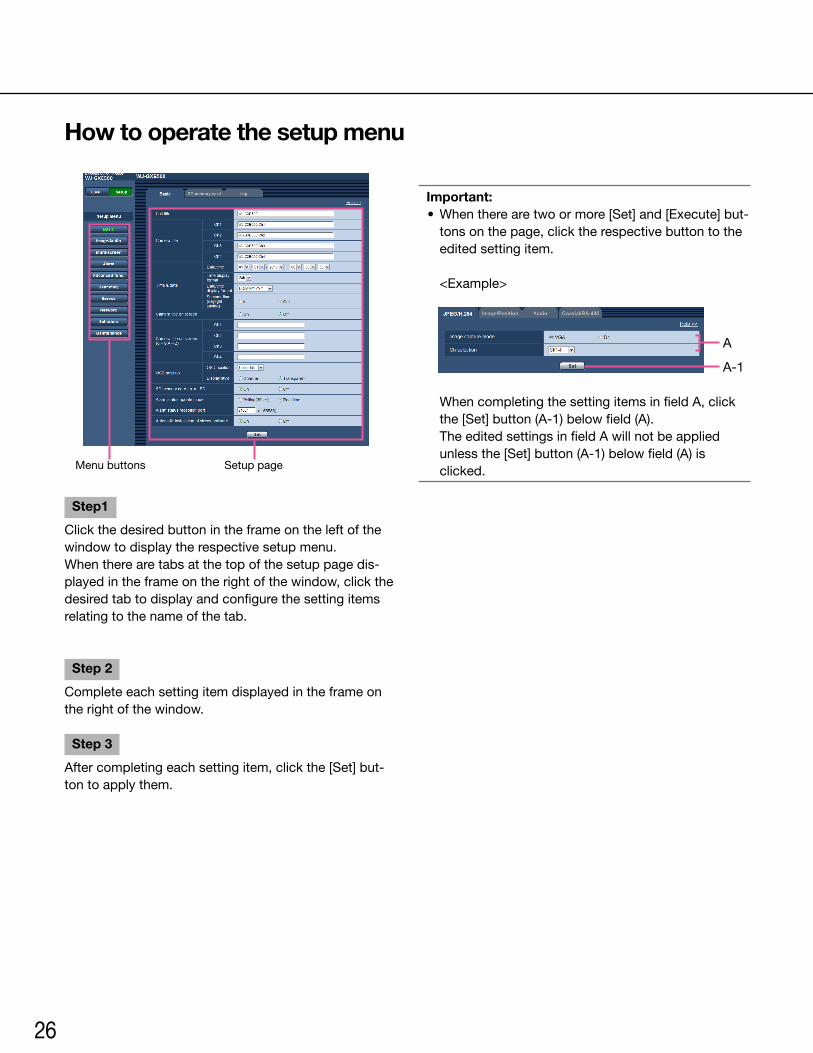
Step1
Click the desired button in the frame on the left of the window to display the respective setup menu.When there are tabs at the top of the setup page dis-played in the frame on the right of the window, click the desired tab to display and configure the setting items relating to the name of the tab.
Step 2
Complete each setting item displayed in the frame on the right of the window.
Step 3
After completing each setting item, click the [Set] but-ton to apply them.
Important: •Whentherearetwoormore[Set]and[Execute]but-
tons on the page, click the respective button to the edited setting item.
<Example>
When completing the setting items in field A, click the [Set] button (A-1) below field (A).
The edited settings in field A will not be applied unless the [Set] button (A-1) below field (A) is clicked.
A
A-1
Menu buttons Setup page
How to operate the setup menu
27
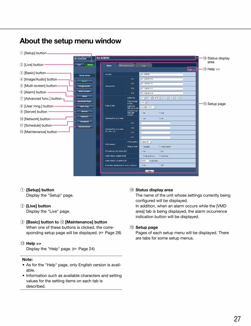
About the setup menu window
q [Setup] button Display the "Setup" page.
w [Live] button Display the "Live" page.
e [Basic] button to !2 [Maintenance] button When one of these buttons is clicked, the corre-
sponding setup page will be displayed. (☞ Page 28)
!3 Help >> Display the "Help" page. (☞ Page 24)
Note: •Asforthe"Help"page,onlyEnglishversionisavail-
able. • Informationsuchasavailablecharactersandsetting
values for the setting items on each tab is described.
!4 Status display area The name of the unit whose settings currently being
configured will be displayed. In addition, when an alarm occurs while the [VMD
area] tab is being displayed, the alarm occurrence indication button will be displayed.
!5 Setup page Pages of each setup menu will be displayed. There
are tabs for some setup menus.
!5 Setup page
!4 Status display area
!3 Help >>w [Live] button
q [Setup] button
e [Basic] button
r [Image/Audio] button
t [Multi-screen] button
y [Alarm] button
u [Advanced func.] button
i [User mng.] button
o [Server] button
!0 [Network] button
!1 [Schedule] button
!2 [Maintenance] button
28
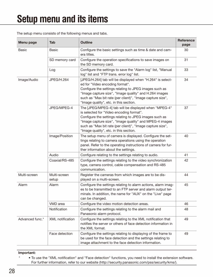
Setup menu and its itemsThe setup menu consists of the following menus and tabs.
Menu page Tab OutlineReference
page
Basic Basic Configure the basic settings such as time & date and cam-era titles.
30
SD memory card Configure the operation specifications to save images on the SD memory card.
31
Log Configure the settings to save the "Alarm log" list, "Manual log" list and "FTP trans. error log" list.
33
Image/Audio JPEG/H.264 [JPEG/H.264] tab will be displayed when "H.264" is select-ed for "Video encoding format". Configure the settings relating to JPEG images such as "Image capture size", "Image quality" and H.264 images such as "Max bit rate (per client)", "Image capture size", "Image quality", etc. in this section.
34
JPEG/MPEG-4 The [JPEG/MPEG-4] tab will be displayed when "MPEG-4" is selected for "Video encoding format". Configure the settings relating to JPEG images such as "Image capture size", "Image quality" and MPEG-4 images such as "Max bit rate (per client)", "Image capture size", "Image quality", etc. in this section.
37
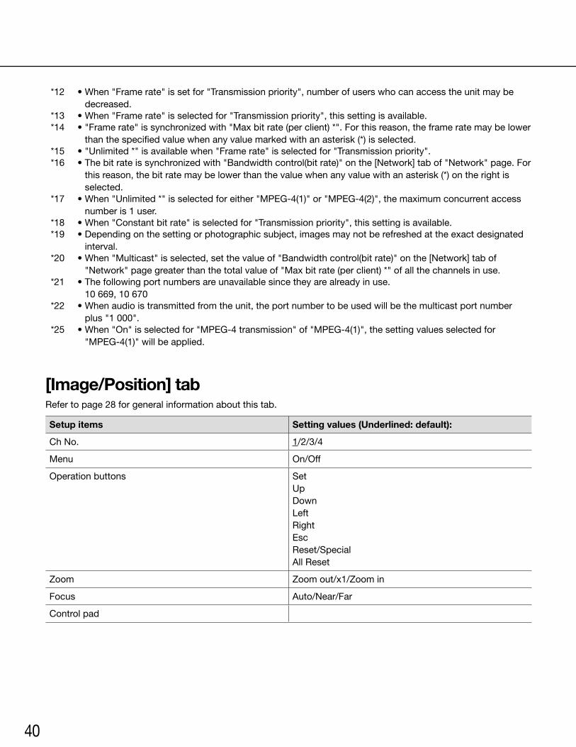
Image/Position The setup menu of camera is displayed. Configure the set-tings relating to camera operations using the operation panel. Refer to the operating instructions of camera for fur-ther information about the settings.
40
Audio Configure relating to the settings relating to audio. 41
Coaxial/RS-485 Configure the settings relating to the video synchronization type, camera control, cable compensation and RS-485 communication.
42
Multi-screen Multi-screen setup
Register the cameras from which images are to be dis-played on a multi-screen.
44
Alarm Alarm Configure the settings relating to alarm actions, alarm imag-es to be transmitted to an FTP server and alarm output ter-minals. In addition, the name for "AUX" on the "Live" page can be changed.
45
VMD area Configure the video motion detection areas. 46
Notification Configure the settings relating to the alarm mail and Panasonic alarm protocol.
48
Advanced func.* XML notification Configure the settings relating to the XML notification that notifies the server or others of face detection information in the XML format.
49
Face detection Configure the settings relating to displaying of the frame to be used for the face detection and the settings relating to image attachment to the face detection information.
49
Important:* • To use the "XML notification" and "Face detection" functions, you need to install the extension software.
For further information, refer to our website (http://security.panasonic.com/pss/security/kms/).

29
Menu page Tab OutlineReference
page
User mng. User auth. Configure the settings relating to the user authentication. 50
Host auth. Configure the restriction settings of PCs (IP address) from accessing the unit.
50
System Configure the settings relating to the priority stream that can transmit images without deteriorating the image quality and refresh interval even when multiple users access concur-rently.
51
Server Mail Configure the settings relating to the mail server used to send the alarm mail.
52
FTP Configure the settings relating to the FTP server used to transmit the alarm images.
52
NTP Configure the settings relating to the NTP server such as the NTP server address, port number, etc.
53
Network Network Configure the network settings. The following information is required to configure the network settings. Contact the net-work administrator or your Internet service provider. •IPaddress •Subnetmask •Defaultgateway(whenusingthegatewayserver/router) •HTTPport •PrimaryDNSaddress
54
DDNS Configure the settings relating to DDNS. To use the DDNS function, it is necessary to connect to the dedicated DDNS server.
55
SNMP Configure the settings relating to SNMP. It is possible to check the status of the unit by connecting to the SNMP manager. When using the SNMP function, contact the net-work administrator.
56
FTP img. trans. Configure the settings relating to the periodic transmission of images to an FTP server. To transmit images to an FTP server periodically, it is necessary to configure the settings of the FTP server in advance.
56
Schedule Schedule Configure the settings relating to schedules of alarm per-mission, VMD permission and access permission.
57
Maintenance System log Displays the system log. 21
Upgrade Upgrade the firmware. The current firmware of this unit can be checked and upgraded to the latest version.
22
Default reset Configurethesettingsofthisunit,initializeandtheHTMLdata or reboot the unit.
23
30
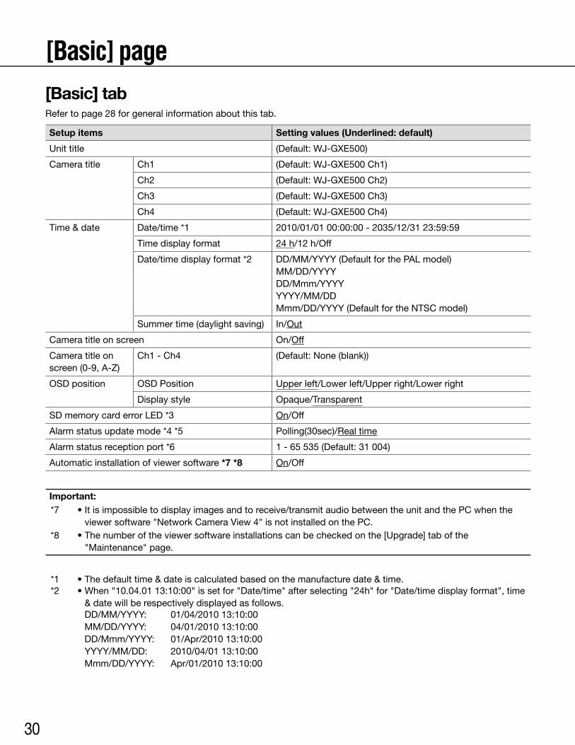
[Basic] page[Basic] tabRefer to page 28 for general information about this tab.
Setup items Setting values (Underlined: default)
Unit title (Default:WJ-GXE500)
Camera title Ch1 (Default:WJ-GXE500Ch1)
Ch2 (Default:WJ-GXE500Ch2)
Ch3 (Default:WJ-GXE500Ch3)
Ch4 (Default:WJ-GXE500Ch4)
Time & date Date/time *1 2010/01/0100:00:00-2035/12/3123:59:59
Time display format 24h/12h/Off
Date/time display format *2 DD/MM/YYYY (Default for the PAL model) MM/DD/YYYY DD/Mmm/YYYY YYYY/MM/DD Mmm/DD/YYYY (Default for the NTSC model)
Summer time (daylight saving) In/Out
Camera title on screen On/Off
Camera title on screen (0-9, A-Z)
Ch1 - Ch4 (Default:None(blank))
OSDposition OSDPosition Upper left/Lower left/Upper right/Lower right
Display style Opaque/Transparent
SD memory card error LED *3 On/Off
Alarm status update mode *4 *5 Polling(30sec)/Real time
Alarm status reception port *6 1-65535(Default:31004)
Automatic installation of viewer software *7 *8 On/Off
Important:*7 •Itisimpossibletodisplayimagesandtoreceive/transmitaudiobetweentheunitandthePCwhenthe
viewer software "Network Camera View 4" is not installed on the PC.*8 •Thenumberoftheviewersoftwareinstallationscanbecheckedonthe[Upgrade]tabofthe
"Maintenance" page.
*1 •Thedefaulttime&dateiscalculatedbasedonthemanufacturedate&time.*2 •When"10.04.0113:10:00"issetfor"Date/time"afterselecting"24h"for"Date/timedisplayformat",time
& date will be respectively displayed as follows.DD/MM/YYYY:MM/DD/YYYY:DD/Mmm/YYYY:YYYY/MM/DD:Mmm/DD/YYYY:
01/04/201013:10:0004/01/201013:10:0001/Apr/201013:10:002010/04/0113:10:00Apr/01/201013:10:00
31
*3 •When"On"isselected,theSDmemorycarderrorLEDwilllightwhendatacannotbesavedontheSDmemory card.
*4 •Selecttheintervaltorefreshthealarmoccurrenceindicationbutton,the[AUX]buttonsandtheSDrecord-ing status indicator on the "Live" page.
*5 •Dependingonthenetworkenvironment,notificationmaynotbeprovidedinrealtime.*6 •Thefollowingportnumbersareunavailablesincetheyarealreadyinuse.
20, 21, 23, 25, 42, 53, 67, 68, 69, 80, 110, 123, 161, 162, 995, 10669, 10670
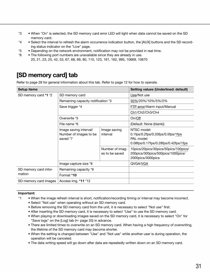
[SD memory card] tabRefer to page 28 for general information about this tab. Refer to page 12 for how to operate.
Setup items Setting values (Underlined: default)
SD memory card *1 *2 SD memory card Use/Not use
Remaining capacity notification *3 50%/20%/10%/5%/2%
Save trigger *4 FTP error/Alarm input/Manual
Ch1/Ch2/Ch3/Ch4
Overwrite*5 On/Off
File name *6 (Default:None(blank))
Image saving interval/Number of images to be saved *7
Image saving interval
NTSCmodel:0.1fps/0.2fps/0.33fps/0.5fps/1fpsPALmodel:0.08fps/0.17fps/0.28fps/0.42fps/1fps
Number of imag-es to be saved
10pics/20pics/30pics/50pics/100pics/200pics/300pics/500pics/1000pics/ 2000pics/3000pics
Imagecapturesize*8 QVGA/VGA
SD memory card infor-mation
Remaining capacity *9
Format *10
SD memory card images Access img. *11 *12
Important:*1 •Whentheimagerefreshintervalisshort,notification/recordingtimingorintervalmaybecomeincorrect.
•Select"Notuse"whenoperatingwithoutanSDmemorycard.•BeforeremovingtheSDmemorycardfromtheunit,itisnecessarytoselect"Notuse"first.•AfterinsertingtheSDmemorycard,itisnecessarytoselect"Use"tousetheSDmemorycard.•WhenplayingordownloadingimagessavedontheSDmemorycard,itisnecessarytoselect"On"for
"Save logs" on the [Log] tab (☞ page 33) in advance.•TherearelimitedtimestooverwriteonanSDmemorycard.Whenhavingahighfrequencyofoverwriting,
the lifetime of the SD memory card may become shorter.•Whenthesettingischangedbetween"Use"and"Notuse"whileanotheruserisduringoperation,the
operation will be canceled.•ThedatawritingspeedwillgodownafterdataarerepeatedlywrittendownonanSDmemorycard.
32
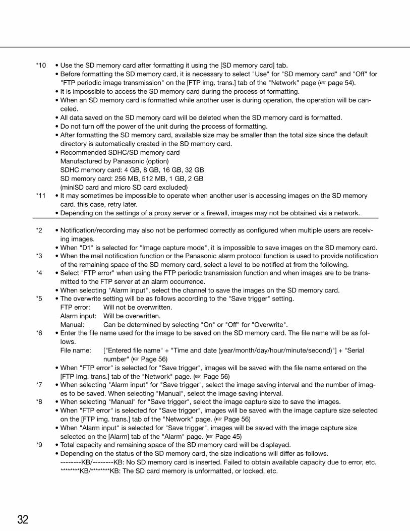
*10 •UsetheSDmemorycardafterformattingitusingthe[SDmemorycard]tab.•BeforeformattingtheSDmemorycard,itisnecessarytoselect"Use"for"SDmemorycard"and"Off"for
"FTP periodic image transmission" on the [FTP img. trans.] tab of the "Network" page (☞ page 54).•ItisimpossibletoaccesstheSDmemorycardduringtheprocessofformatting.•WhenanSDmemorycardisformattedwhileanotheruserisduringoperation,theoperationwillbecan-
celed.•AlldatasavedontheSDmemorycardwillbedeletedwhentheSDmemorycardisformatted.•Donotturnoffthepoweroftheunitduringtheprocessofformatting.•AfterformattingtheSDmemorycard,availablesizemaybesmallerthanthetotalsizesincethedefault
directory is automatically created in the SD memory card.•RecommendedSDHC/SDmemorycard
Manufactured by Panasonic (option) SDHCmemorycard:4GB,8GB,16GB,32GB SDmemorycard:256MB,512MB,1GB,2GB (miniSD card and micro SD card excluded)
*11 •ItmaysometimesbeimpossibletooperatewhenanotheruserisaccessingimagesontheSDmemorycard. this case, retry later.
•Dependingonthesettingsofaproxyserverorafirewall,imagesmaynotbeobtainedviaanetwork.
*2 •Notification/recordingmayalsonotbeperformedcorrectlyasconfiguredwhenmultipleusersarereceiv-ing images.
•When"D1"isselectedfor"Imagecapturemode",itisimpossibletosaveimagesontheSDmemorycard.*3 •WhenthemailnotificationfunctionorthePanasonicalarmprotocolfunctionisusedtoprovidenotification
of the remaining space of the SD memory card, select a level to be notified at from the following. *4 •Select"FTPerror"whenusingtheFTPperiodictransmissionfunctionandwhenimagesaretobetrans-
mitted to the FTP server at an alarm occurrence.•Whenselecting"Alarminput",selectthechanneltosavetheimagesontheSDmemorycard.
*5 •Theoverwritesettingwillbeasfollowsaccordingtothe"Savetrigger"setting. FTPerror: Willnotbeoverwritten. Alarminput: Willbeoverwritten. Manual: Canbedeterminedbyselecting"On"or"Off"for"Overwrite".
*6 •EnterthefilenameusedfortheimagetobesavedontheSDmemorycard.Thefilenamewillbeasfol-lows. Filename: ["Enteredfilename"+"Timeanddate(year/month/day/hour/minute/second)"]+"Serial
number" (☞ Page 56)•When"FTPerror"isselectedfor"Savetrigger",imageswillbesavedwiththefilenameenteredonthe
[FTP img. trans.] tab of the "Network" page. (☞ Page 56)*7 •Whenselecting"Alarminput"for"Savetrigger",selecttheimagesavingintervalandthenumberofimag-
es to be saved. When selecting "Manual", select the image saving interval.*8 •Whenselecting"Manual"for"Savetrigger",selecttheimagecapturesizetosavetheimages.
•When"FTPerror"isselectedfor"Savetrigger",imageswillbesavedwiththeimagecapturesizeselectedon the [FTP img. trans.] tab of the "Network" page. (☞ Page 56)
•When"Alarminput"isselectedfor"Savetrigger",imageswillbesavedwiththeimagecapturesizeselected on the [Alarm] tab of the "Alarm" page. (☞ Page 45)
*9 •TotalcapacityandremainingspaceoftheSDmemorycardwillbedisplayed.•DependingonthestatusoftheSDmemorycard,thesizeindicationswilldifferasfollows. --------KB/--------KB:NoSDmemorycardisinserted.Failedtoobtainavailablecapacityduetoerror,etc.
********KB/********KB:TheSDcardmemoryisunformatted,orlocked,etc.
33
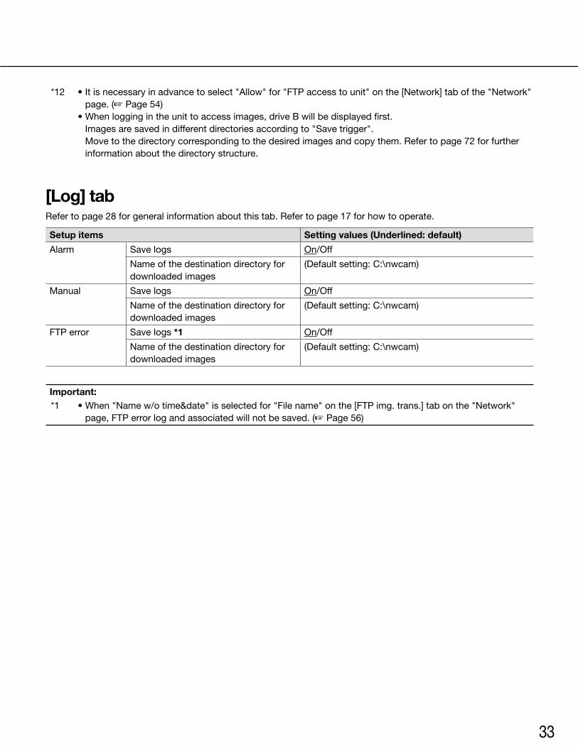
*12 •Itisnecessaryinadvancetoselect"Allow"for"FTPaccesstounit"onthe[Network]tabofthe"Network"page. (☞ Page 54)
•Whenloggingintheunittoaccessimages,driveBwillbedisplayedfirst. Images are saved in different directories according to "Save trigger". Move to the directory corresponding to the desired images and copy them. Refer to page 72 for further information about the directory structure.
[Log] tabRefer to page 28 for general information about this tab. Refer to page 17 for how to operate.
Setup items Setting values (Underlined: default)
Alarm Save logs On/Off
Name of the destination directory for downloaded images
(Defaultsetting:C:\nwcam)
Manual Save logs On/Off
Name of the destination directory for downloaded images
(Defaultsetting:C:\nwcam)
FTP error Save logs *1 On/Off
Name of the destination directory for downloaded images
(Defaultsetting:C:\nwcam)
Important:*1 •When"Namew/otime&date"isselectedfor"Filename"onthe[FTPimg.trans.]tabonthe"Network"
page, FTP error log and associated will not be saved. (☞ Page 56)
34
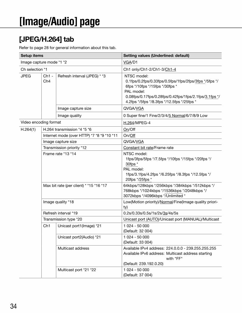
[Image/Audio] page[JPEG/H.264] tabRefer to page 28 for general information about this tab.
Setup items Setting values (Underlined: default)
Image capture mode *1 *2 VGA/D1
Ch selection *1 Ch1 only/Ch1-2/Ch1-3/Ch1-4
JPEG Ch1 - Ch4
Refresh interval (JPEG) * *3 NTSCmodel:0.1fps/0.2fps/0.33fps/0.5fps/1fps/2fps/3fps */5fps */ 6fps */10fps */15fps */30fps * PALmodel:0.08fps/0.17fps/0.28fps/0.42fps/1fps/2.1fps/3.1fps */ 4.2fps */5fps */8.3fps */12.5fps */25fps *
Imagecapturesize QVGA/VGA
Image quality 0 Super fine/1 Fine/2/3/4/5 Normal/6/7/8/9 Low
Video encoding format H.264/MPEG-4
H.264(1) H.264 transmission *4 *5 *6 On/Off
Internet mode (over HTTP) *7 *8 *9 *10 *11 On/Off
Imagecapturesize QVGA/VGA
Transmission priority *12 Constant bit rate/Frame rate
Frame rate *13 *14 NTSCmodel:1fps/3fps/5fps */7.5fps */10fps */15fps */20fps */ 30fps *
PALmodel:1fps/3.1fps/4.2fps */6.25fps */8.3fps */12.5fps */20fps */25fps *
Max bit rate (per client) * *15 *16 *17 64kbps/128kbps */256kbps */384kbps */512kbps */ 768kbps */1024kbps */1536kbps */2048kbps */ 3072kbps */4096kbps */Unlimited *
Image quality *18 Low(Motion priority)/Normal/Fine(Image quality priori-ty)
Refresh interval *19 0.2s/0.33s/0.5s/1s/2s/3s/4s/5s
Transmission type *20 Unicastport(AUTO)/Unicastport(MANUAL)/Multicast
Ch1 Unicast port1(Image) *21 1 024 - 50 000 (Default:32004)
Unicast port2(Audio) *21 1 024 - 50 000 (Default:33004)
Multicast address AvailableIPv4address: 224.0.0.0-239.255.255.255AvailableIPv6address: Multicastaddressstarting
with "FF"(Default:239.192.0.20)
Multicast port *21 *22 1 024 - 50 000 (Default:37004)
35
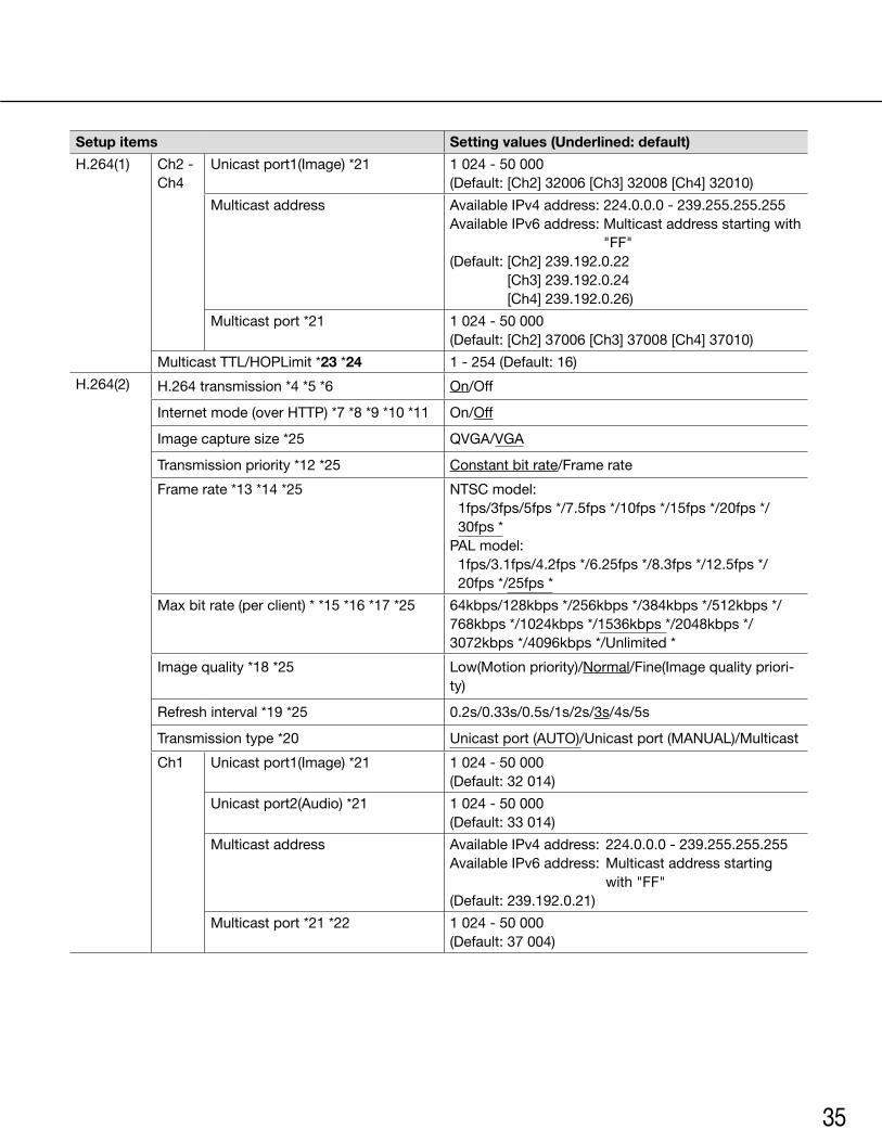
Setup items Setting values (Underlined: default)
H.264(1) Ch2 - Ch4
Unicast port1(Image) *21 1 024 - 50 000(Default:[Ch2]32006[Ch3]32008[Ch4]32010)
Multicast address AvailableIPv4address:224.0.0.0-239.255.255.255AvailableIPv6address:Multicastaddressstartingwith
"FF"(Default:[Ch2]239.192.0.22
[Ch3] 239.192.0.24 [Ch4] 239.192.0.26)
Multicast port *21 1 024 - 50 000(Default:[Ch2]37006[Ch3]37008[Ch4]37010)
MulticastTTL/HOPLimit*23 *24 1-254(Default:16)
H.264(2) H.264 transmission *4 *5 *6 On/Off
Internet mode (over HTTP) *7 *8 *9 *10 *11 On/Off
Imagecapturesize*25 QVGA/VGA
Transmission priority *12 *25 Constant bit rate/Frame rate
Frame rate *13 *14 *25 NTSCmodel:1fps/3fps/5fps */7.5fps */10fps */15fps */20fps */ 30fps *
PALmodel:1fps/3.1fps/4.2fps */6.25fps */8.3fps */12.5fps */20fps */25fps *
Max bit rate (per client) * *15 *16 *17 *25 64kbps/128kbps */256kbps */384kbps */512kbps */ 768kbps */1024kbps */1536kbps */2048kbps */ 3072kbps */4096kbps */Unlimited *
Image quality *18 *25 Low(Motion priority)/Normal/Fine(Image quality priori-ty)
Refresh interval *19 *25 0.2s/0.33s/0.5s/1s/2s/3s/4s/5s
Transmission type *20 Unicastport(AUTO)/Unicastport(MANUAL)/Multicast
Ch1 Unicast port1(Image) *21 1 024 - 50 000 (Default:32014)
Unicast port2(Audio) *21 1 024 - 50 000 (Default:33014)
Multicast address AvailableIPv4address: 224.0.0.0-239.255.255.255AvailableIPv6address: Multicastaddressstarting
with "FF"(Default:239.192.0.21)
Multicast port *21 *22 1 024 - 50 000 (Default:37004)
36
Setup items Setting values (Underlined: default)
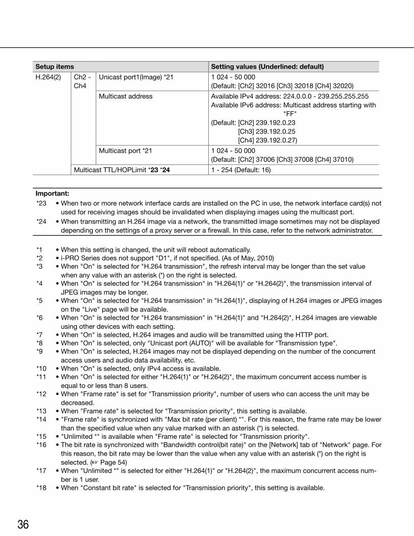
H.264(2) Ch2 - Ch4
Unicast port1(Image) *21 1 024 - 50 000(Default:[Ch2]32016[Ch3]32018[Ch4]32020)
Multicast address AvailableIPv4address:224.0.0.0-239.255.255.255AvailableIPv6address:Multicastaddressstartingwith
"FF"(Default:[Ch2]239.192.0.23
[Ch3] 239.192.0.25 [Ch4] 239.192.0.27)
Multicast port *21 1 024 - 50 000(Default:[Ch2]37006[Ch3]37008[Ch4]37010)
MulticastTTL/HOPLimit*23 *24 1-254(Default:16)
Important:*23 •WhentwoormorenetworkinterfacecardsareinstalledonthePCinuse,thenetworkinterfacecard(s)not
used for receiving images should be invalidated when displaying images using the multicast port.*24 •WhentransmittinganH.264imageviaanetwork,thetransmittedimagesometimesmaynotbedisplayed
depending on the settings of a proxy server or a firewall. In this case, refer to the network administrator.
*1 •Whenthissettingischanged,theunitwillrebootautomatically.*2 •i-PROSeriesdoesnotsupport"D1",ifnotspecified.(AsofMay,2010)*3 •When"On"isselectedfor"H.264transmission",therefreshintervalmaybelongerthanthesetvalue
when any value with an asterisk (*) on the right is selected.*4 •When"On"isselectedfor"H.264transmission"in"H.264(1)"or"H.264(2)",thetransmissionintervalof
JPEG images may be longer.*5 •When"On"isselectedfor"H.264transmission"in"H.264(1)",displayingofH.264imagesorJPEGimages
on the "Live" page will be available.*6 •When"On"isselectedfor"H.264transmission"in"H.264(1)"and"H.264(2)",H.264imagesareviewable
using other devices with each setting.*7 •When"On"isselected,H.264imagesandaudiowillbetransmittedusingtheHTTPport.*8 •When"On"isselected,only"Unicastport(AUTO)"willbeavailablefor"Transmissiontype".*9 •When"On"isselected,H.264imagesmaynotbedisplayeddependingonthenumberoftheconcurrent
access users and audio data availability, etc.*10 •When"On"isselected,onlyIPv4accessisavailable.*11 •When"On"isselectedforeither"H.264(1)"or"H.264(2)",themaximumconcurrentaccessnumberis
equal to or less than 8 users.*12 •When"Framerate"issetfor"Transmissionpriority",numberofuserswhocanaccesstheunitmaybe
decreased.*13 •When"Framerate"isselectedfor"Transmissionpriority",thissettingisavailable.*14 •"Framerate"issynchronizedwith"Maxbitrate(perclient)*".Forthisreason,theframeratemaybelower
than the specified value when any value marked with an asterisk (*) is selected.*15 •"Unlimited*"isavailablewhen"Framerate"isselectedfor"Transmissionpriority".*16 •Thebitrateissynchronizedwith"Bandwidthcontrol(bitrate)"onthe[Network]tabof"Network"page.For
this reason, the bit rate may be lower than the value when any value with an asterisk (*) on the right is selected. (☞ Page 54)
*17 •When"Unlimited*"isselectedforeither"H.264(1)"or"H.264(2)",themaximumconcurrentaccessnum-ber is 1 user.
*18 •When"Constantbitrate"isselectedfor"Transmissionpriority",thissettingisavailable.
37
*19 •Dependingonthesettingorphotographicsubject,imagesmaynotberefreshedattheexactdesignatedinterval.
*20 •When"Multicast"isselected,setthevalueof"Bandwidthcontrol(bitrate)"onthe[Network]tabof"Network" page greater than the total value of "Max bit rate (per client) *" of all the channels in use. (☞ Page 54)
*21 •Thefollowingportnumbersareunavailablesincetheyarealreadyinuse. 10 669, 10 670
*22 •Whenaudioistransmittedfromtheunit,theportnumbertobeusedwillbethemulticastportnumberplus "1 000".
*25 •When"On"isselectedfor"H.264transmission"of"H.264(1)",thesettingvaluesselectedfor"H.264(1)"will be applied.
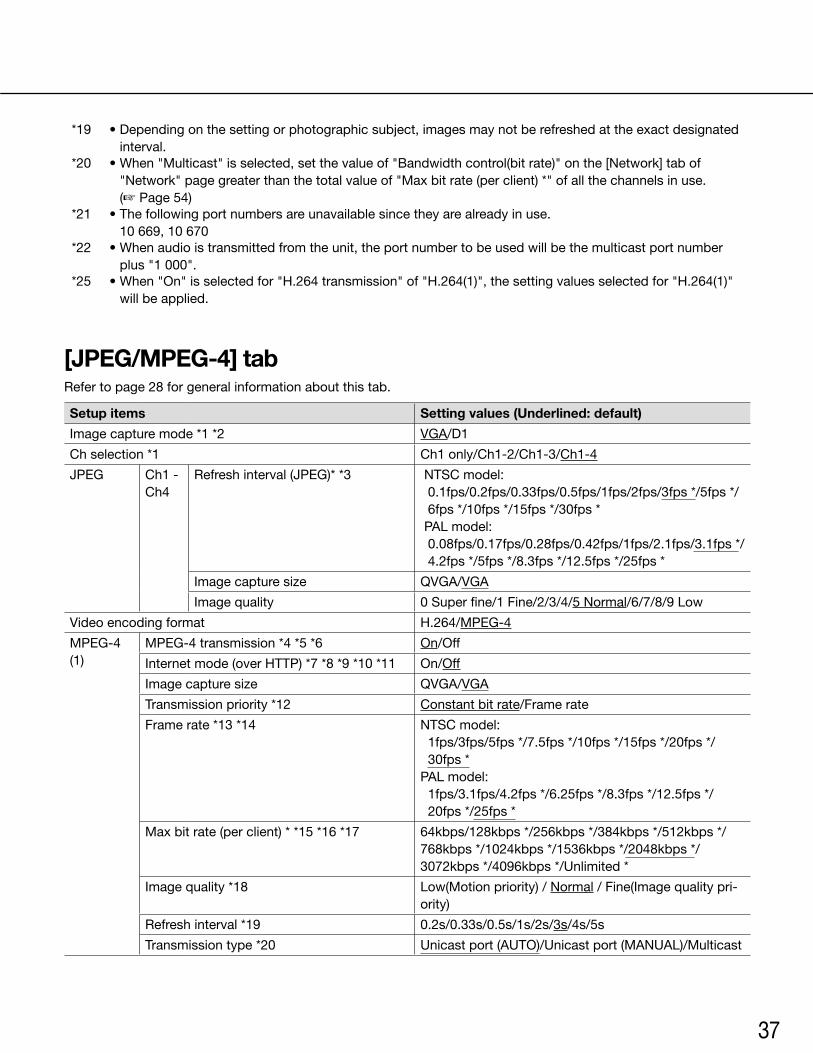
[JPEG/MPEG-4] tabRefer to page 28 for general information about this tab.
Setup items Setting values (Underlined: default)
Image capture mode *1 *2 VGA/D1
Ch selection *1 Ch1 only/Ch1-2/Ch1-3/Ch1-4
JPEG Ch1 - Ch4
Refresh interval (JPEG)* *3 NTSCmodel:0.1fps/0.2fps/0.33fps/0.5fps/1fps/2fps/3fps */5fps */ 6fps */10fps */15fps */30fps * PALmodel:0.08fps/0.17fps/0.28fps/0.42fps/1fps/2.1fps/3.1fps */ 4.2fps */5fps */8.3fps */12.5fps */25fps *
Imagecapturesize QVGA/VGA
Image quality 0 Super fine/1 Fine/2/3/4/5 Normal/6/7/8/9 Low
Video encoding format H.264/MPEG-4
MPEG-4 (1)
MPEG-4 transmission *4 *5 *6 On/Off
Internet mode (over HTTP) *7 *8 *9 *10 *11 On/Off
Imagecapturesize QVGA/VGA
Transmission priority *12 Constant bit rate/Frame rate
Frame rate *13 *14 NTSCmodel:1fps/3fps/5fps */7.5fps */10fps */15fps */20fps */ 30fps *
PALmodel:1fps/3.1fps/4.2fps */6.25fps */8.3fps */12.5fps */20fps */25fps *
Max bit rate (per client) * *15 *16 *17 64kbps/128kbps */256kbps */384kbps */512kbps */ 768kbps */1024kbps */1536kbps */2048kbps */ 3072kbps */4096kbps */Unlimited *
Image quality *18 Low(Motion priority) / Normal / Fine(Image quality pri-ority)
Refresh interval *19 0.2s/0.33s/0.5s/1s/2s/3s/4s/5s
Transmission type *20 Unicastport(AUTO)/Unicastport(MANUAL)/Multicast
38
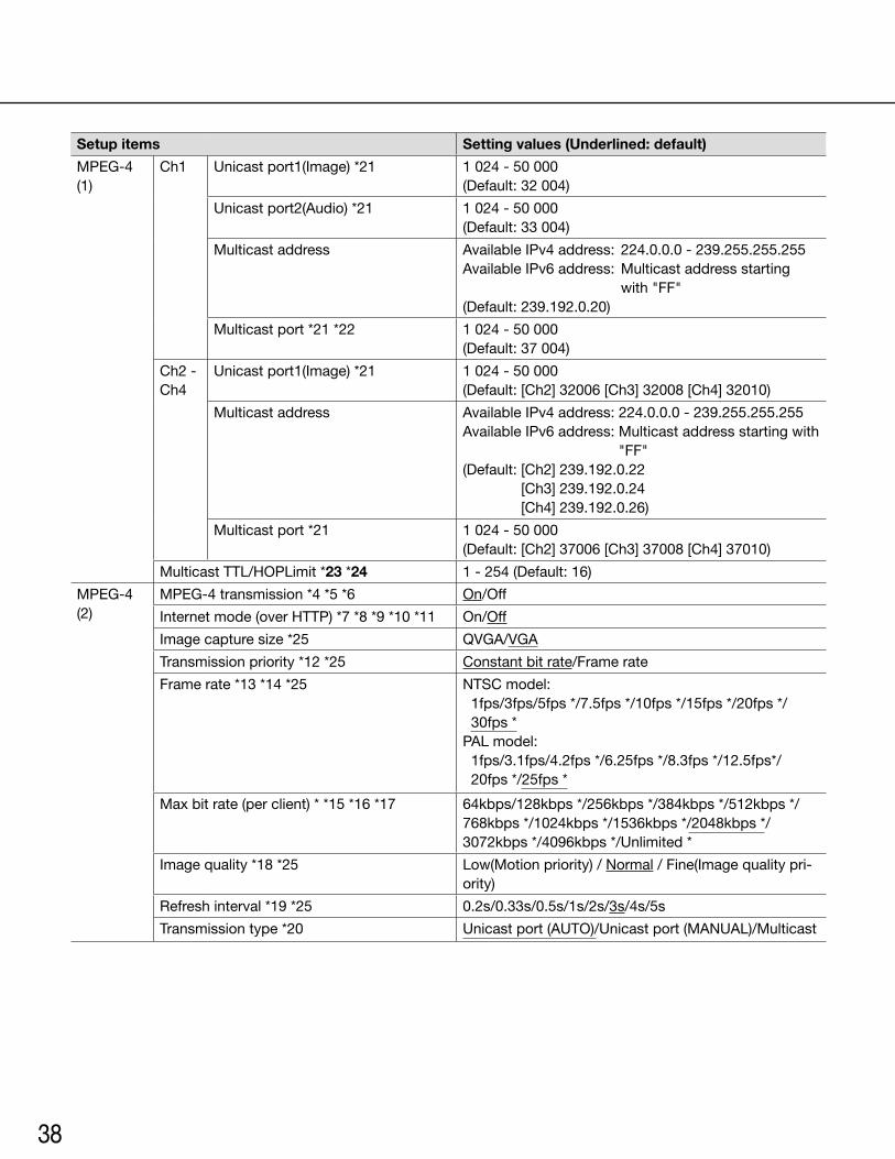
Setup items Setting values (Underlined: default)
MPEG-4 (1)
Ch1 Unicast port1(Image) *21 1 024 - 50 000 (Default:32004)
Unicast port2(Audio) *21 1 024 - 50 000 (Default:33004)
Multicast address AvailableIPv4address: 224.0.0.0-239.255.255.255AvailableIPv6address: Multicastaddressstarting
with "FF"(Default:239.192.0.20)
Multicast port *21 *22 1 024 - 50 000 (Default:37004)
Ch2 - Ch4
Unicast port1(Image) *21 1 024 - 50 000(Default:[Ch2]32006[Ch3]32008[Ch4]32010)
Multicast address AvailableIPv4address:224.0.0.0-239.255.255.255AvailableIPv6address:Multicastaddressstartingwith
"FF"(Default:[Ch2]239.192.0.22
[Ch3] 239.192.0.24 [Ch4] 239.192.0.26)
Multicast port *21 1 024 - 50 000(Default:[Ch2]37006[Ch3]37008[Ch4]37010)
MulticastTTL/HOPLimit*23 *24 1-254(Default:16)
MPEG-4 (2)
MPEG-4 transmission *4 *5 *6 On/Off
Internet mode (over HTTP) *7 *8 *9 *10 *11 On/Off
Imagecapturesize*25 QVGA/VGA
Transmission priority *12 *25 Constant bit rate/Frame rate
Frame rate *13 *14 *25 NTSCmodel:1fps/3fps/5fps */7.5fps */10fps */15fps */20fps */ 30fps *
PALmodel:1fps/3.1fps/4.2fps */6.25fps */8.3fps */12.5fps*/20fps */25fps *
Max bit rate (per client) * *15 *16 *17 64kbps/128kbps */256kbps */384kbps */512kbps */ 768kbps */1024kbps */1536kbps */2048kbps */ 3072kbps */4096kbps */Unlimited *
Image quality *18 *25 Low(Motion priority) / Normal / Fine(Image quality pri-ority)
Refresh interval *19 *25 0.2s/0.33s/0.5s/1s/2s/3s/4s/5s
Transmission type *20 Unicastport(AUTO)/Unicastport(MANUAL)/Multicast
39
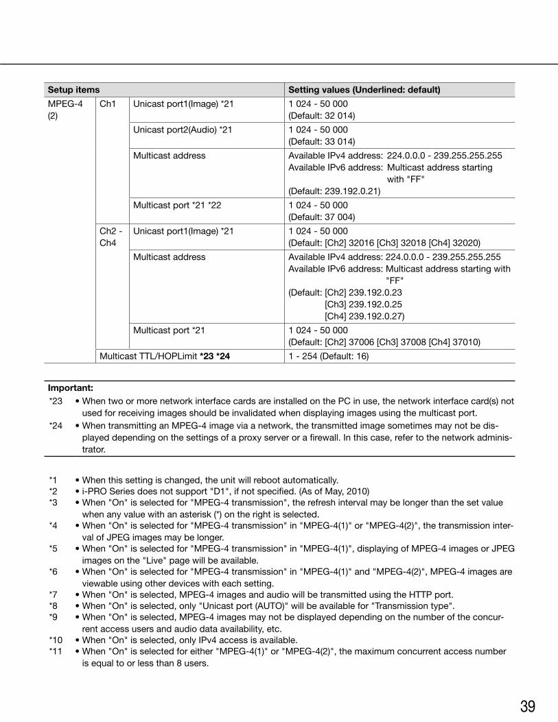
Setup items Setting values (Underlined: default)
MPEG-4 (2)
Ch1 Unicast port1(Image) *21 1 024 - 50 000 (Default:32014)
Unicast port2(Audio) *21 1 024 - 50 000 (Default:33014)
Multicast address AvailableIPv4address: 224.0.0.0-239.255.255.255AvailableIPv6address: Multicastaddressstarting
with "FF"(Default:239.192.0.21)
Multicast port *21 *22 1 024 - 50 000 (Default:37004)
Ch2 - Ch4
Unicast port1(Image) *21 1 024 - 50 000(Default:[Ch2]32016[Ch3]32018[Ch4]32020)
Multicast address AvailableIPv4address:224.0.0.0-239.255.255.255AvailableIPv6address:Multicastaddressstartingwith
"FF"(Default:[Ch2]239.192.0.23
[Ch3] 239.192.0.25 [Ch4] 239.192.0.27)
Multicast port *21 1 024 - 50 000(Default:[Ch2]37006[Ch3]37008[Ch4]37010)
MulticastTTL/HOPLimit*23 *24 1-254(Default:16)
Important:*23 •WhentwoormorenetworkinterfacecardsareinstalledonthePCinuse,thenetworkinterfacecard(s)not
used for receiving images should be invalidated when displaying images using the multicast port.*24 •WhentransmittinganMPEG-4imageviaanetwork,thetransmittedimagesometimesmaynotbedis-
played depending on the settings of a proxy server or a firewall. In this case, refer to the network adminis-trator.
*1 •Whenthissettingischanged,theunitwillrebootautomatically.*2 •i-PROSeriesdoesnotsupport"D1",ifnotspecified.(AsofMay,2010)*3 •When"On"isselectedfor"MPEG-4transmission",therefreshintervalmaybelongerthanthesetvalue
when any value with an asterisk (*) on the right is selected.*4 •When"On"isselectedfor"MPEG-4transmission"in"MPEG-4(1)"or"MPEG-4(2)",thetransmissioninter-
val of JPEG images may be longer.*5 •When"On"isselectedfor"MPEG-4transmission"in"MPEG-4(1)",displayingofMPEG-4imagesorJPEG
images on the "Live" page will be available.*6 •When"On"isselectedfor"MPEG-4transmission"in"MPEG-4(1)"and"MPEG-4(2)",MPEG-4imagesare
viewable using other devices with each setting.*7 •When"On"isselected,MPEG-4imagesandaudiowillbetransmittedusingtheHTTPport.*8 •When"On"isselected,only"Unicastport(AUTO)"willbeavailablefor"Transmissiontype".*9 •When"On"isselected,MPEG-4imagesmaynotbedisplayeddependingonthenumberoftheconcur-
rent access users and audio data availability, etc.*10 •When"On"isselected,onlyIPv4accessisavailable.*11 •When"On"isselectedforeither"MPEG-4(1)"or"MPEG-4(2)",themaximumconcurrentaccessnumber
is equal to or less than 8 users.
40
*12 •When"Framerate"issetfor"Transmissionpriority",numberofuserswhocanaccesstheunitmaybedecreased.
*13 •When"Framerate"isselectedfor"Transmissionpriority",thissettingisavailable.*14 •"Framerate"issynchronizedwith"Maxbitrate(perclient)*".Forthisreason,theframeratemaybelower
than the specified value when any value marked with an asterisk (*) is selected.*15 •"Unlimited*"isavailablewhen"Framerate"isselectedfor"Transmissionpriority".*16 •Thebitrateissynchronizedwith"Bandwidthcontrol(bitrate)"onthe[Network]tabof"Network"page.For
this reason, the bit rate may be lower than the value when any value with an asterisk (*) on the right is selected.
*17 •When"Unlimited*"isselectedforeither"MPEG-4(1)"or"MPEG-4(2)",themaximumconcurrentaccessnumber is 1 user.
*18 •When"Constantbitrate"isselectedfor"Transmissionpriority",thissettingisavailable.*19 •Dependingonthesettingorphotographicsubject,imagesmaynotberefreshedattheexactdesignated
interval.*20 •When"Multicast"isselected,setthevalueof"Bandwidthcontrol(bitrate)"onthe[Network]tabof
"Network" page greater than the total value of "Max bit rate (per client) *" of all the channels in use.*21 •Thefollowingportnumbersareunavailablesincetheyarealreadyinuse.
10 669, 10 670*22 •Whenaudioistransmittedfromtheunit,theportnumbertobeusedwillbethemulticastportnumber
plus "1 000".*25 •When"On"isselectedfor"MPEG-4transmission"of"MPEG-4(1)",thesettingvaluesselectedfor
"MPEG-4(1)" will be applied.
[Image/Position] tabRefer to page 28 for general information about this tab.
Setup items Setting values (Underlined: default):
Ch No. 1/2/3/4
Menu On/Off
Operationbuttons SetUpDownLeftRightEscReset/SpecialAll Reset
Zoom Zoom out/x1/Zoom in
Focus Auto/Near/Far
Control pad
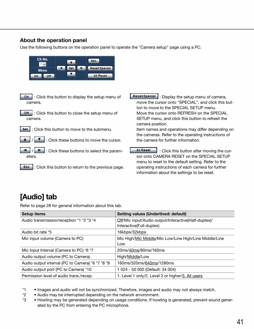
41
:Clickthisbuttontodisplaythesetupmenuofcamera.
:Clickthisbuttontoclosethesetupmenuofcamera.
:Clickthisbuttontomovetothesubmenu.
/ :Clickthesebuttonstomovethecursor.
/ :Clickthesebuttonstoselecttheparam-eters.
:Clickthisbuttontoreturntothepreviouspage.
:Displaythesetupmenuofcamera,move the cursor onto "SPECIAL", and click this but-ton to move to the SPECIAL SETUP menu.
Move the cursor onto REFRESH on the SPECIAL SETUP menu, and click this button to refresh the camera position.
Item names and operations may differ depending on the cameras. Refer to the operating instructions of the camera for further information.
:Clickthisbuttonaftermovingthecur-sor onto CAMERA RESET on the SPECIAL SETUP menu to reset to the default setting. Refer to the operating instructions of each camera for further information about the settings to be reset.
About the operation panelUse the following buttons on the operation panel to operate the "Camera setup" page using a PC.
[Audio] tabRefer to page 28 for general information about this tab.
Setup items Setting values (Underlined: default)
Audio transmission/reception *1 *2 *3 *4 Off/Mic input/Audio output/Interactive(Half-duplex)/Interactive(Full-duplex)
Audio bit rate *5 16kbps/32kbps
Mic input volume (Camera to PC) Mic High/Mic Middle/Mic Low/Line High/Line Middle/Line Low
Mic Input Interval (Camera to PC) *6 *7 20ms/40ms/80ms/160ms
Audio output volume (PC to Camera) High/Middle/Low
Audio output interval (PC to Camera) *6 *7 *8 *9 160ms/320ms/640ms/1280ms
Audio output port (PC to Camera) *10 1024-50000(Default:34004)
Permission level of audio trans./recep. 1. Level 1 only/2. Level 2 or higher/3. All users
*1 •Imagesandaudiowillnotbesynchronized.Therefore,imagesandaudiomaynotalwaysmatch.*2 •Audiomaybeinterrupteddependingonthenetworkenvironment.*3 •Howlingmaybegenerateddependingonusageconditions.Ifhowlingisgenerated,preventsoundgener-
ated by the PC from entering the PC microphone.
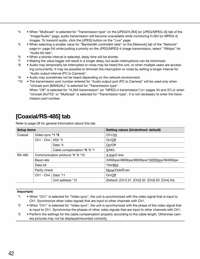
42
*4 •When"Multicast"isselectedfor"Transmissiontype"onthe[JPEG/H.264](or[JPEG/MPEG-4])tabofthe"Image/Audio" page, audio transmission will become unavailable while monitoring H.264 (or MPEG-4) images. To transmit audio, click the [JPEG] button on the "Live" page.
*5 •Whenselectingasmallervaluefor"Bandwidthcontrol(bitrate)"onthe[Network]tabofthe"Network"page (☞ page 54) while putting a priority on the JPEG/MPEG-4 image transmission, select "16kbps" for "Audio bit rate".
*6 •Whenashorterintervalisselected,delaytimewillbeshorter.*7 •Makingthevaluebiggerwillresultinalongerdelay,butaudiointerruptionscanbeminimized.*8 •Audiomaytemporarilybeinterruptedornoisemaybeheardtheunit,orwhenmultipleusersareaccess-
ing concurrently. It may be possible to diminish the interruption or noise by setting a longer interval for "Audio output interval (PC to Camera)".
*9 •Audiomaysometimesnotbehearddependingonthenetworkenvironment.*10 •Thetransmissionportnumberenteredfor"Audiooutputport(PCtoCamera)"willbeusedonlywhen
"Unicast port (MANUAL)" is selected for "Transmission type". When"Off"isselectedfor"H.264transmission"(or"MPEG-4transmission")(☞ pages 34 and 37) or when "Unicast(AUTO)"or"Multicast"isselectedfor"Transmissiontype",itisnotnecessarytoenterthetrans-mission port number.
[Coaxial/RS-485] tabRefer to page 28 for general information about this tab.
Setup items Setting values (Underlined: default)
Coaxial Video sync *1 *2 Ch1/Int
Ch1 - Ch4 VD2 *3 On/Off
Data *4 On/Off
Cable compensation *5 *6 *7 S/M/L
RS-485 Communication protocol *8 *9 *10 4-line/2-line
Baud rate 2400bps/4800bps/9600bps/19200bps/38400bps
Data bit 7bit/8bit
Parity check None/Odd/Even
Ch1 - Ch4 Data *11 On/Off
Unit address *12 (Default:[Ch1]01[Ch2]02[Ch3]03[Ch4]04)
Important:
*1 •When"Ch1"isselectedfor"Videosync",theunitissynchronizedwiththevideosignalthatisinputtoCh1.SynchronizeothervideosignalsthatareinputtootherchannelswithCh1.
*2 •When"Ch1"isselectedfor"Videosync",theunitissynchronizedwiththephaseofthevideosignalthatisinputtoCh1.SynchronizethephasesofothervideosignalsthatareinputtootherchannelswithCh1.
*5 •Performthesettingsforthecablecompensationproperlyaccordingtothecablelength.Otherwisecam-era pictures may not be displayed/recorded correctly.
43
*3 •Select"On"or"Off"todeterminewhetherornottoapplytheVD2synchronizationmethodforthecon-nectedcamera.WhenacameranotsupportingtheVD2synchronizationmethodisconnected,select"Off"for"VD2".
*4 •Select"On"tocontrolcameraswiththecoaxialcommunication.*6 •Itispossibletocompensateforthevideosignaltransmissionlossfromthecamera.*7 •ThefollowingcablelengthsettingsarereferenceswhenusingRG-59/U,BELDEN9259(forNTSCmod-
els), 5C-2V (for PAL models) or equivalent cables. S:Lessthan400m{1300ft.} M:400m{1300ft.}to700m{2300ft.} L:700m{2300ft.}to1200m{4000ft.}
*8 •WhencameraswiththedifferentRS-485protocols(forexample,camerasmanufacturedbyPanasonicand those manufactured by Pelco, Inc.) in the same RS-485 communication line, the cameras will not work correctly.
*9 •Selectthecommunicationprotocolthatiscompliantwiththespecificationsoftheconnectedcameras.*10 • RefertothereadmefileontheprovidedCD-ROMforfurtherinformationabouttheRS-485command
table.*11 •Select"On"tocontrolcameraswiththeRS-485communication.*12 •SetthevalueinaccordancewiththeRS-485commandtable.Refertothereadmefileontheprovided
CD-ROMforfurtherdetails.

44
[Multi-screen] page[Multi-screen setup] tabRefer to page 28 for general information about this tab. Refer to page 12 for how to operate.
Setup items Setting values (Underlined: default)
Group A Cam. 1 - Cam. 4 IP address *1 *2 (Default:None(blank))
Ch No. *3 −/Ch1/Ch2/Ch3/Ch4
Camera title *4 (Default:None(blank))
Group B Cam. 5 - Cam. 8 IP address *1 *2 (Default:None(blank))
Ch No. *3 −/Ch1/Ch2/Ch3/Ch4
Camera title *4 (Default:None(blank))
Group C Cam. 9 - Cam. 12 IP address *1 *2 (Default:None(blank))
Ch No. *3 −/Ch1/Ch2/Ch3/Ch4
Camera title *4 (Default:None(blank))
Group D Cam. 13 - Cam. 16 IP address *1 *2 (Default:None(blank))
Ch No. *3 −/Ch1/Ch2/Ch3/Ch4
Camera title *4 (Default:None(blank))
*1 •Whenusingthehostname,itisnecessarytoconfiguretheDNSsettingsofthePCtobeusedforthemulti-screen display. (☞ Page 54)
*2 •Regardlessofthesettingsoftheregistereddevice,theimageswillbedisplayedalteredtotheaspectratioof4:3onamulti-screen.
*3 •Select"–"whendisplayingimagesonamulti-screenusingadevicewithoutchannelinformation.*4 •Whenselectinga16split-screen,somecharactersofthecameratitletobedisplayedmaynotbedis-
played.
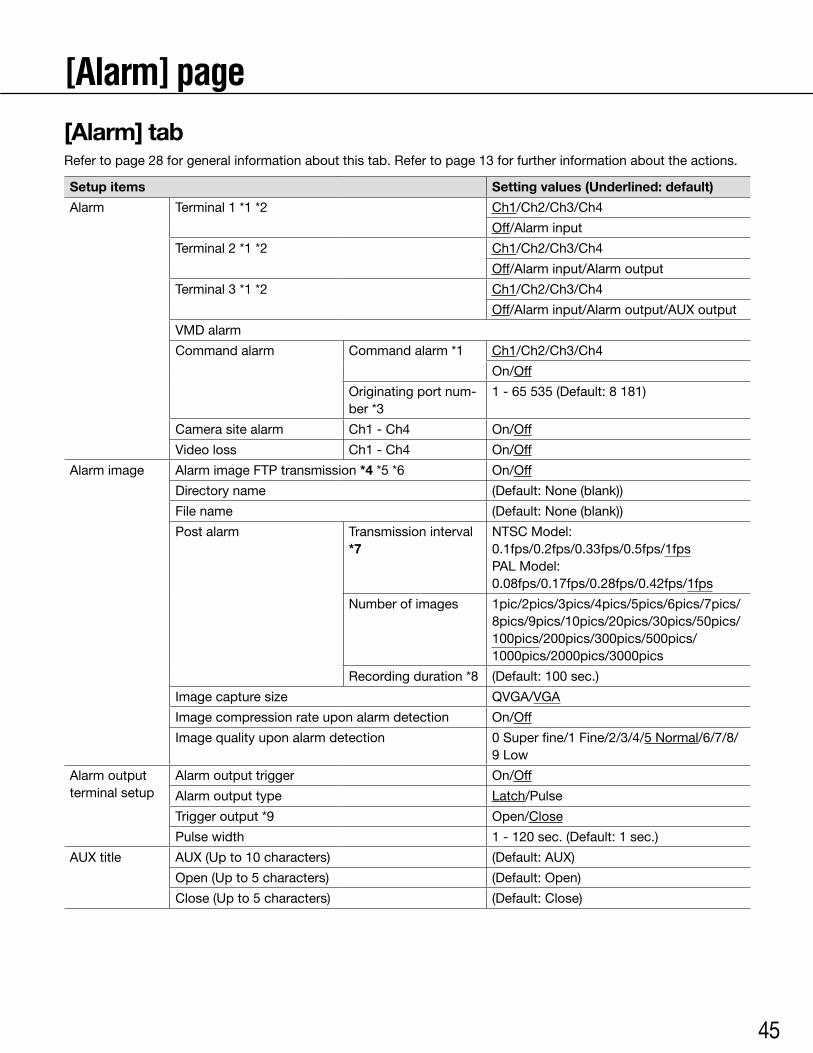
45
[Alarm] page[Alarm] tabRefer to page 28 for general information about this tab. Refer to page 13 for further information about the actions.
Setup items Setting values (Underlined: default)
Alarm Terminal 1 *1 *2 Ch1/Ch2/Ch3/Ch4
Off/Alarm input
Terminal 2 *1 *2 Ch1/Ch2/Ch3/Ch4
Off/Alarm input/Alarm output
Terminal 3 *1 *2 Ch1/Ch2/Ch3/Ch4
Off/Alarm input/Alarm output/AUX output
VMD alarm
Command alarm Command alarm *1 Ch1/Ch2/Ch3/Ch4
On/Off
Originatingportnum-ber *3
1-65535(Default:8181)
Camera site alarm Ch1 - Ch4 On/Off
Video loss Ch1 - Ch4 On/Off
Alarm image Alarm image FTP transmission *4 *5 *6 On/Off
Directory name (Default:None(blank))
File name (Default:None(blank))
Post alarm Transmission interval *7
NTSCModel: 0.1fps/0.2fps/0.33fps/0.5fps/1fpsPALModel:0.08fps/0.17fps/0.28fps/0.42fps/1fps
Number of images 1pic/2pics/3pics/4pics/5pics/6pics/7pics/8pics/9pics/10pics/20pics/30pics/50pics/100pics/200pics/300pics/500pics/1000pics/2000pics/3000pics
Recording duration *8 (Default:100sec.)
Imagecapturesize QVGA/VGA
Image compression rate upon alarm detection On/Off
Image quality upon alarm detection 0 Super fine/1 Fine/2/3/4/5 Normal/6/7/8/ 9 Low
Alarm output terminal setup
Alarm output trigger On/Off
Alarm output type Latch/Pulse
Trigger output *9 Open/Close
Pulse width 1-120sec.(Default:1sec.)
AUX title AUX (Up to 10 characters) (Default:AUX)
Open(Upto5characters) (Default:Open)
Close (Up to 5 characters) (Default:Close)
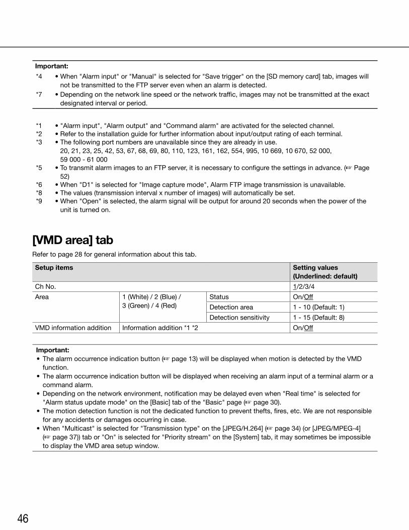
46
Important:
*4 •When"Alarminput"or"Manual"isselectedfor"Savetrigger"onthe[SDmemorycard]tab,imageswillnot be transmitted to the FTP server even when an alarm is detected.
*7 •Dependingonthenetworklinespeedorthenetworktraffic,imagesmaynotbetransmittedattheexactdesignated interval or period.
*1 •"Alarminput","Alarmoutput"and"Commandalarm"areactivatedfortheselectedchannel.*2 •Refertotheinstallationguideforfurtherinformationaboutinput/outputratingofeachterminal.*3 •Thefollowingportnumbersareunavailablesincetheyarealreadyinuse.
20, 21, 23, 25, 42, 53, 67, 68, 69, 80, 110, 123, 161, 162, 554, 995, 10 669, 10 670, 52 000, 59 000 - 61 000
*5 •TotransmitalarmimagestoanFTPserver,itisnecessarytoconfigurethesettingsinadvance.(☞ Page 52)
*6 •When"D1"isselectedfor"Imagecapturemode",AlarmFTPimagetransmissionisunavailable.*8 •Thevalues(transmissionintervalxnumberofimages)willautomaticallybeset.*9 •When"Open"isselected,thealarmsignalwillbeoutputforaround20secondswhenthepowerofthe
unit is turned on.
[VMD area] tabRefer to page 28 for general information about this tab.
Setup items Setting values (Underlined: default)
Ch No. 1/2/3/4
Area 1 (White) / 2 (Blue) / 3 (Green) / 4 (Red)
Status On/Off
Detection area 1-10(Default:1)
Detection sensitivity 1-15(Default:8)
VMD information addition Information addition *1 *2 On/Off
Important: • Thealarmoccurrenceindicationbutton(☞ page 13) will be displayed when motion is detected by the VMD
function. • Thealarmoccurrenceindicationbuttonwillbedisplayedwhenreceivinganalarminputofaterminalalarmora
command alarm. •Dependingonthenetworkenvironment,notificationmaybedelayedevenwhen"Realtime"isselectedfor
"Alarm status update mode" on the [Basic] tab of the "Basic" page (☞ page 30). • Themotiondetectionfunctionisnotthededicatedfunctiontopreventthefts,fires,etc.Wearenotresponsible
for any accidents or damages occurring in case. •When"Multicast"isselectedfor"Transmissiontype"onthe[JPEG/H.264](☞ page 34) (or [JPEG/MPEG-4]
(☞page37))tabor"On"isselectedfor"Prioritystream"onthe[System]tab,itmaysometimesbeimpossibleto display the VMD area setup window.
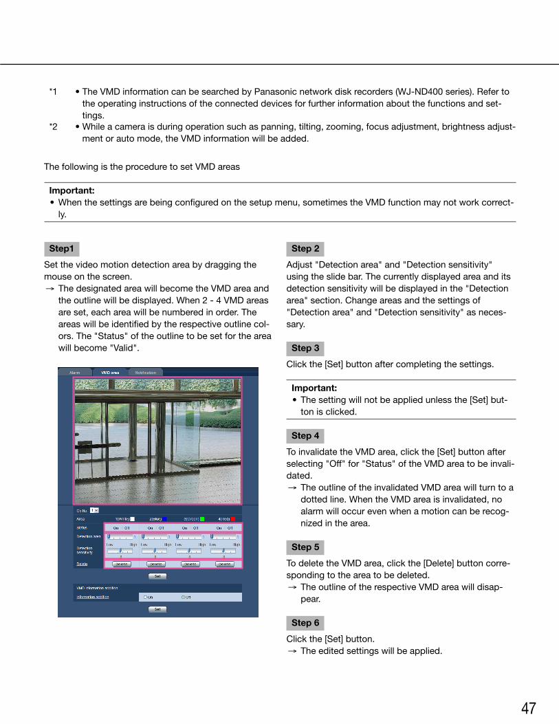
47
*1 •TheVMDinformationcanbesearchedbyPanasonicnetworkdiskrecorders(WJ-ND400series).Refertothe operating instructions of the connected devices for further information about the functions and set-tings.
*2 •Whileacameraisduringoperationsuchaspanning,tilting,zooming,focusadjustment,brightnessadjust-ment or auto mode, the VMD information will be added.
The following is the procedure to set VMD areas
Important: •Whenthesettingsarebeingconfiguredonthesetupmenu,sometimestheVMDfunctionmaynotworkcorrect-
ly.
Step1
Set the video motion detection area by dragging the mouse on the screen. → The designated area will become the VMD area and
the outline will be displayed. When 2 - 4 VMD areas are set, each area will be numbered in order. The areas will be identified by the respective outline col-ors. The "Status" of the outline to be set for the area will become "Valid".
Step 2
Adjust "Detection area" and "Detection sensitivity" using the slide bar. The currently displayed area and its detection sensitivity will be displayed in the "Detection area" section. Change areas and the settings of "Detection area" and "Detection sensitivity" as neces-sary.
Step 3
Click the [Set] button after completing the settings.
Important: • Thesettingwillnotbeappliedunlessthe[Set]but-
ton is clicked.
Step 4
To invalidate the VMD area, click the [Set] button after selecting"Off"for"Status"oftheVMDareatobeinvali-dated. → The outline of the invalidated VMD area will turn to a
dotted line. When the VMD area is invalidated, no alarm will occur even when a motion can be recog-nizedinthearea.
Step 5
To delete the VMD area, click the [Delete] button corre-sponding to the area to be deleted. → The outline of the respective VMD area will disap-
pear.
Step 6
Click the [Set] button. → The edited settings will be applied.
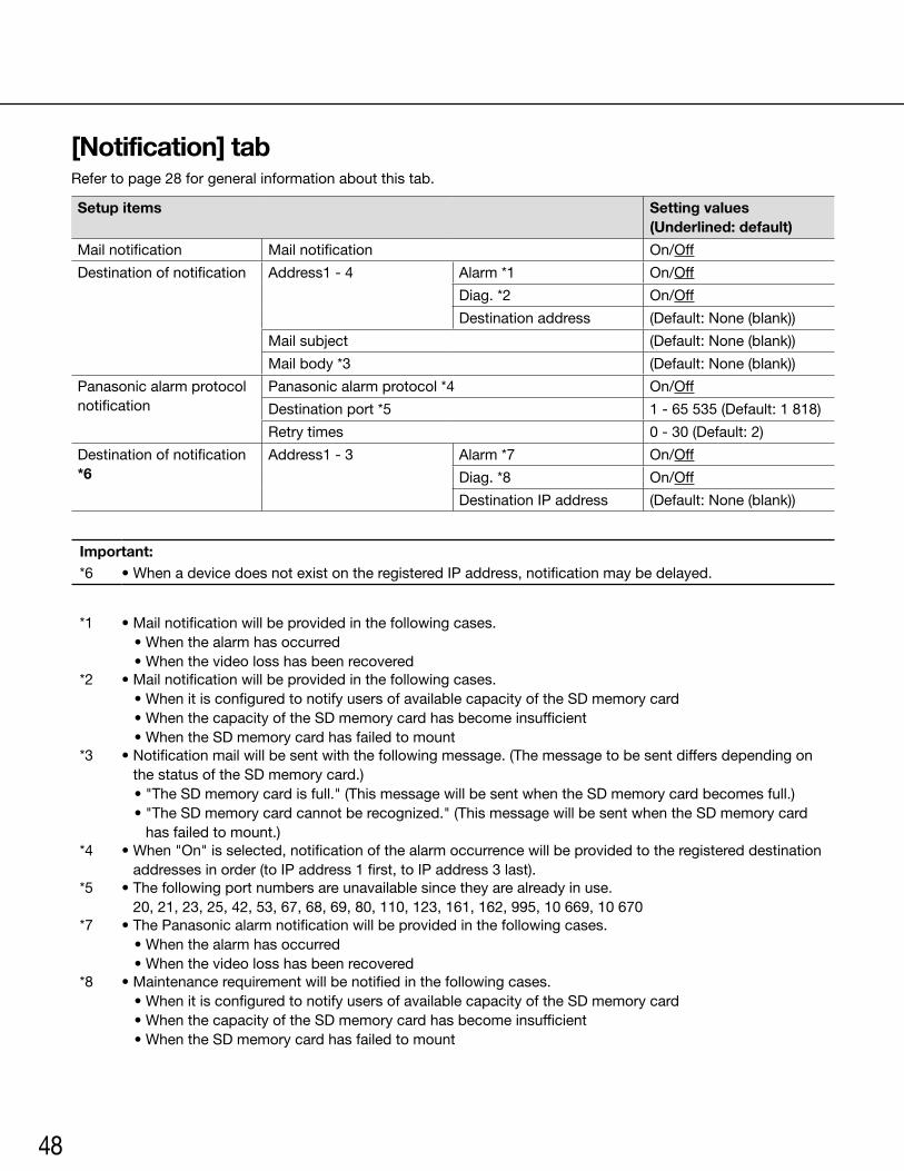
48
[Notification] tabRefer to page 28 for general information about this tab.
Setup items Setting values (Underlined: default)
Mail notification Mail notification On/Off
Destination of notification Address1 - 4 Alarm *1 On/Off
Diag. *2 On/Off
Destination address (Default: None (blank))
Mail subject (Default: None (blank))
Mail body *3 (Default: None (blank))
Panasonic alarm protocol notification
Panasonic alarm protocol *4 On/Off
Destination port *5 1 - 65 535 (Default: 1 818)
Retry times 0 - 30 (Default: 2)
Destination of notification *6
Address1 - 3 Alarm *7 On/Off
Diag. *8 On/Off
Destination IP address (Default: None (blank))
Important:*6 • When a device does not exist on the registered IP address, notification may be delayed.
*1 • Mail notification will be provided in the following cases.• When the alarm has occurred• When the video loss has been recovered
*2 • Mail notification will be provided in the following cases.• When it is configured to notify users of available capacity of the SD memory card • When the capacity of the SD memory card has become insufficient • When the SD memory card has failed to mount
*3 • Notification mail will be sent with the following message. (The message to be sent differs depending on the status of the SD memory card.)• "The SD memory card is full." (This message will be sent when the SD memory card becomes full.)• "The SD memory card cannot be recognized." (This message will be sent when the SD memory card
has failed to mount.)*4 • When "On" is selected, notification of the alarm occurrence will be provided to the registered destination
addresses in order (to IP address 1 first, to IP address 3 last).*5 • The following port numbers are unavailable since they are already in use.
20, 21, 23, 25, 42, 53, 67, 68, 69, 80, 110, 123, 161, 162, 995, 10 669, 10 670*7 • The Panasonic alarm notification will be provided in the following cases.
• When the alarm has occurred• When the video loss has been recovered
*8 • Maintenance requirement will be notified in the following cases. • When it is configured to notify users of available capacity of the SD memory card • When the capacity of the SD memory card has become insufficient • When the SD memory card has failed to mount
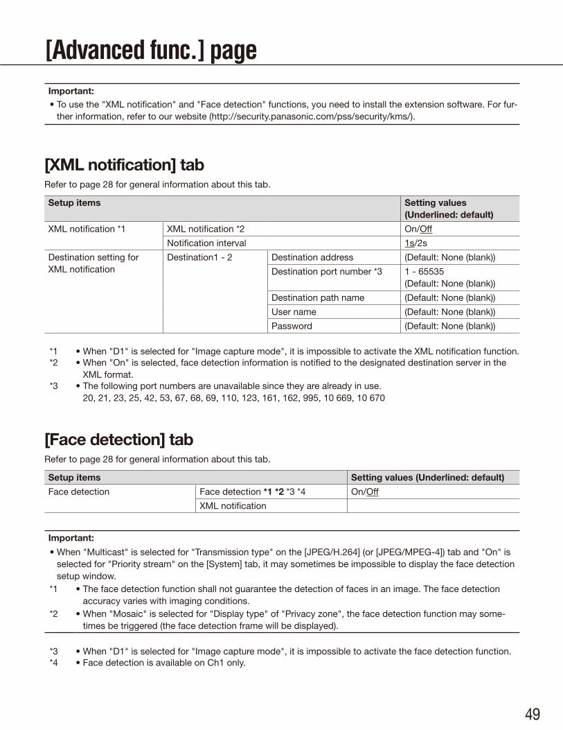
49
[Advanced func.] page
[XML notification] tabRefer to page 28 for general information about this tab.
Setup items Setting values (Underlined: default)
XML notification *1 XML notification *2 On/Off
Notification interval 1s/2s
Destination setting for XML notification
Destination1 - 2 Destination address (Default: None (blank))
Destination port number *3 1 - 65535(Default: None (blank))
Destination path name (Default: None (blank))
User name (Default: None (blank))
Password (Default: None (blank))
*1 • When "D1" is selected for "Image capture mode", it is impossible to activate the XML notification function.*2 • When "On" is selected, face detection information is notified to the designated destination server in the
XML format.*3 • The following port numbers are unavailable since they are already in use.
20, 21, 23, 25, 42, 53, 67, 68, 69, 110, 123, 161, 162, 995, 10 669, 10 670
[Face detection] tabRefer to page 28 for general information about this tab.
Setup items Setting values (Underlined: default)
Face detection Face detection *1 *2 *3 *4 On/Off
XML notification
Important:
• When "Multicast" is selected for "Transmission type" on the [JPEG/H.264] (or [JPEG/MPEG-4]) tab and "On" is selected for "Priority stream" on the [System] tab, it may sometimes be impossible to display the face detection setup window.
*1 • The face detection function shall not guarantee the detection of faces in an image. The face detection accuracy varies with imaging conditions.
*2 • When "Mosaic" is selected for "Display type" of "Privacy zone", the face detection function may some-times be triggered (the face detection frame will be displayed).
*3 • When "D1" is selected for "Image capture mode", it is impossible to activate the face detection function.*4 • Face detection is available on Ch1 only.
Important:• To use the "XML notification" and "Face detection" functions, you need to install the extension software. For fur-
ther information, refer to our website (http://security.panasonic.com/pss/security/kms/).
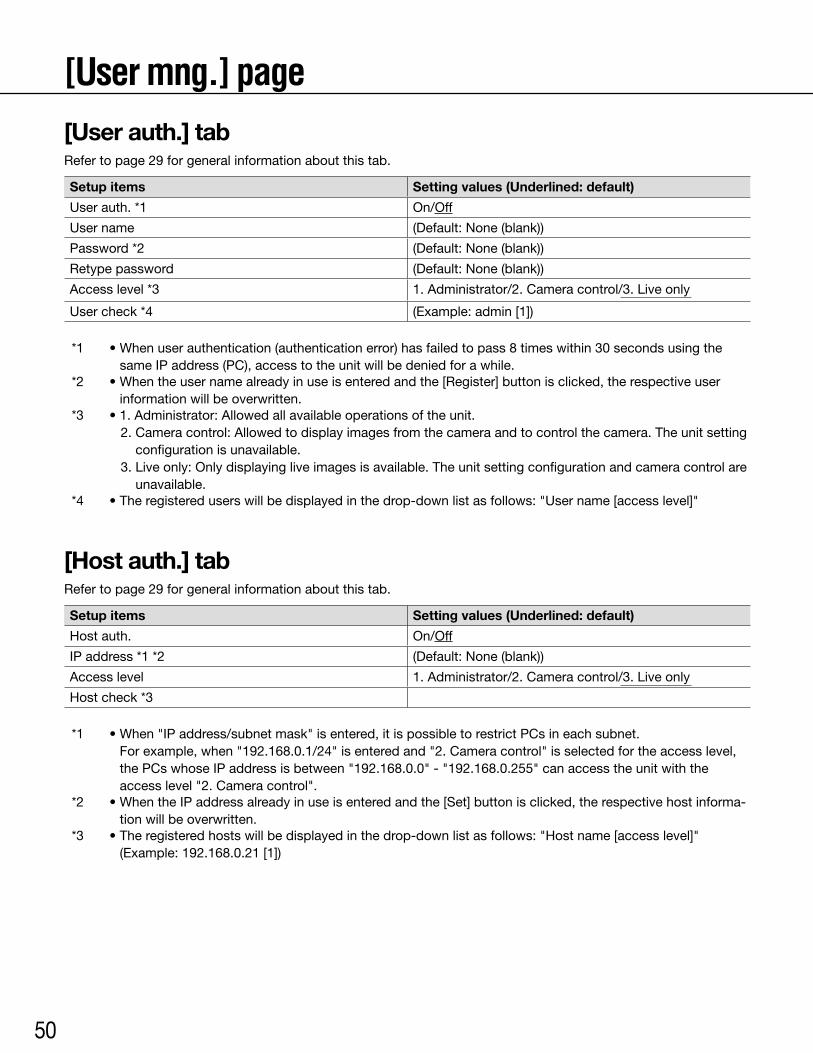
50
[User mng.] page[User auth.] tabRefer to page 29 for general information about this tab.
Setup items Setting values (Underlined: default)
User auth. *1 On/Off
User name (Default:None(blank))
Password *2 (Default:None(blank))
Retype password (Default:None(blank))
Access level *3 1. Administrator/2. Camera control/3. Live only
User check *4 (Example:admin[1])
*1 •Whenuserauthentication(authenticationerror)hasfailedtopass8timeswithin30secondsusingthesame IP address (PC), access to the unit will be denied for a while.
*2 •Whentheusernamealreadyinuseisenteredandthe[Register]buttonisclicked,therespectiveuserinformation will be overwritten.
*3 •1.Administrator:Allowedallavailableoperationsoftheunit.2.Cameracontrol:Allowedtodisplayimagesfromthecameraandtocontrolthecamera.Theunitsetting
configuration is unavailable.3.Liveonly:Onlydisplayingliveimagesisavailable.Theunitsettingconfigurationandcameracontrolare
unavailable.*4 •Theregistereduserswillbedisplayedinthedrop-downlistasfollows:"Username[accesslevel]"
[Host auth.] tabRefer to page 29 for general information about this tab.
Setup items Setting values (Underlined: default)
Host auth. On/Off
IP address *1 *2 (Default:None(blank))
Access level 1. Administrator/2. Camera control/3. Live only
Host check *3
*1 •When"IPaddress/subnetmask"isentered,itispossibletorestrictPCsineachsubnet. For example, when "192.168.0.1/24" is entered and "2. Camera control" is selected for the access level, the PCs whose IP address is between "192.168.0.0" - "192.168.0.255" can access the unit with the access level "2. Camera control".
*2 •WhentheIPaddressalreadyinuseisenteredandthe[Set]buttonisclicked,therespectivehostinforma-tion will be overwritten.
*3 •Theregisteredhostswillbedisplayedinthedrop-downlistasfollows:"Hostname[accesslevel]" (Example:192.168.0.21[1])
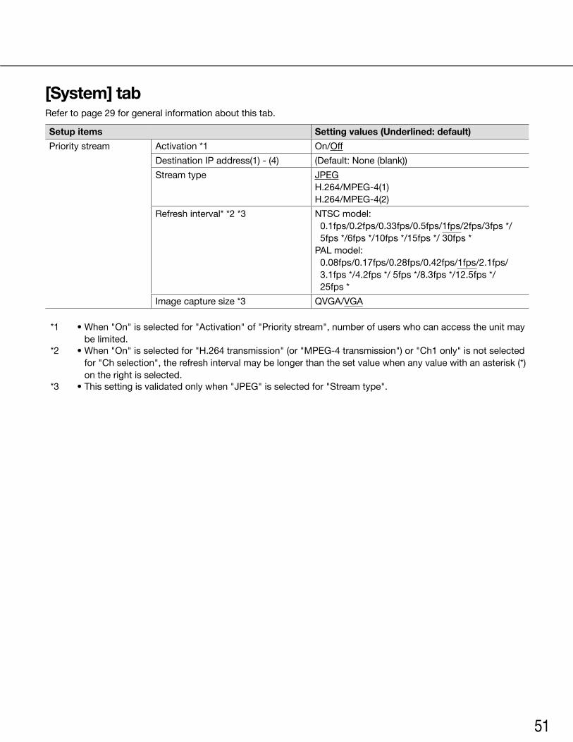
51
[System] tabRefer to page 29 for general information about this tab.
Setup items Setting values (Underlined: default)
Priority stream Activation *1 On/Off
Destination IP address(1) - (4) (Default:None(blank))
Stream type JPEGH.264/MPEG-4(1)H.264/MPEG-4(2)
Refresh interval* *2 *3 NTSCmodel:0.1fps/0.2fps/0.33fps/0.5fps/1fps/2fps/3fps */ 5fps */6fps */10fps */15fps */ 30fps *
PALmodel:0.08fps/0.17fps/0.28fps/0.42fps/1fps/2.1fps/3.1fps */4.2fps */ 5fps */8.3fps */12.5fps */25fps *
Imagecapturesize*3 QVGA/VGA
*1 •When"On"isselectedfor"Activation"of"Prioritystream",numberofuserswhocanaccesstheunitmaybe limited.
*2 •When"On"isselectedfor"H.264transmission"(or"MPEG-4transmission")or"Ch1only"isnotselectedfor "Ch selection", the refresh interval may be longer than the set value when any value with an asterisk (*) on the right is selected.
*3 •Thissettingisvalidatedonlywhen"JPEG"isselectedfor"Streamtype".
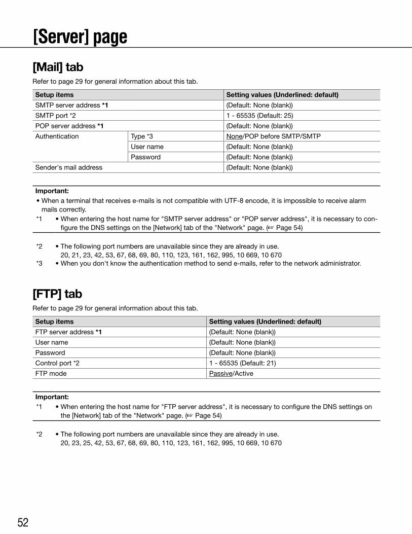
52
[Server] page[Mail] tabRefer to page 29 for general information about this tab.
Setup items Setting values (Underlined: default)
SMTP server address *1 (Default:None(blank))
SMTP port *2 1-65535(Default:25)
POPserveraddress*1 (Default:None(blank))
Authentication Type *3 None/POPbeforeSMTP/SMTP
User name (Default:None(blank))
Password (Default:None(blank))
Sender's mail address (Default:None(blank))
Important:•Whenaterminalthatreceivese-mailsisnotcompatiblewithUTF-8encode,itisimpossibletoreceivealarm
mails correctly.*1 •Whenenteringthehostnamefor"SMTPserveraddress"or"POPserveraddress",itisnecessarytocon-
figure the DNS settings on the [Network] tab of the "Network" page. (☞ Page 54)
*2 •Thefollowingportnumbersareunavailablesincetheyarealreadyinuse. 20, 21, 23, 42, 53, 67, 68, 69, 80, 110, 123, 161, 162, 995, 10 669, 10 670
*3 •Whenyoudon'tknowtheauthenticationmethodtosende-mails,refertothenetworkadministrator.
[FTP] tabRefer to page 29 for general information about this tab.
Setup items Setting values (Underlined: default)
FTP server address *1 (Default:None(blank))
User name (Default:None(blank))
Password (Default:None(blank))
Control port *2 1-65535(Default:21)
FTP mode Passive/Active
Important:*1 •Whenenteringthehostnamefor"FTPserveraddress",itisnecessarytoconfiguretheDNSsettingson
the [Network] tab of the "Network" page. (☞ Page 54)
*2 •Thefollowingportnumbersareunavailablesincetheyarealreadyinuse. 20, 23, 25, 42, 53, 67, 68, 69, 80, 110, 123, 161, 162, 995, 10 669, 10 670
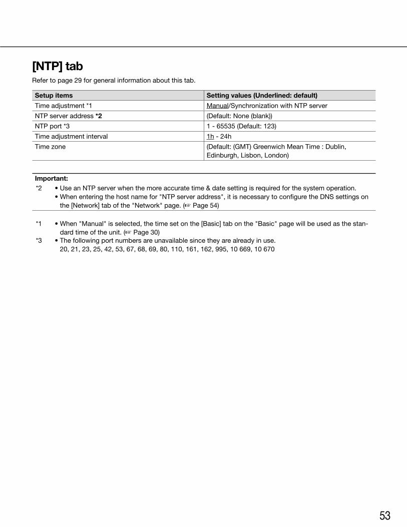
53
[NTP] tabRefer to page 29 for general information about this tab.
Setup items Setting values (Underlined: default)
Time adjustment *1 Manual/SynchronizationwithNTPserver
NTP server address *2 (Default:None(blank))
NTP port *3 1-65535(Default:123)
Time adjustment interval 1h - 24h
Timezone (Default:(GMT)GreenwichMeanTime:Dublin,Edinburgh, Lisbon, London)
Important:*2 •UseanNTPserverwhenthemoreaccuratetime&datesettingisrequiredforthesystemoperation.
•Whenenteringthehostnamefor"NTPserveraddress",itisnecessarytoconfiguretheDNSsettingsonthe [Network] tab of the "Network" page. (☞ Page 54)
*1 •When"Manual"isselected,thetimesetonthe[Basic]tabonthe"Basic"pagewillbeusedasthestan-dard time of the unit. (☞ Page 30)
*3 •Thefollowingportnumbersareunavailablesincetheyarealreadyinuse. 20, 21, 23, 25, 42, 53, 67, 68, 69, 80, 110, 161, 162, 995, 10 669, 10 670
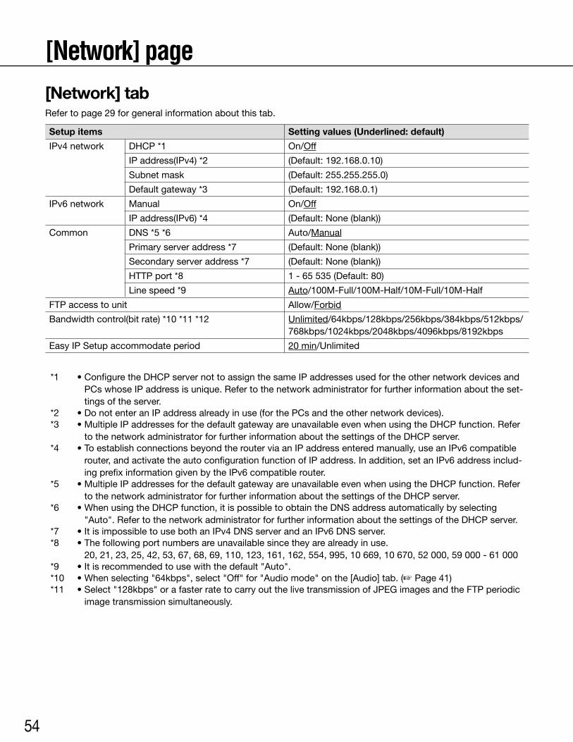
54
[Network] page[Network] tabRefer to page 29 for general information about this tab.
Setup items Setting values (Underlined: default)
IPv4 network DHCP *1 On/Off
IP address(IPv4) *2 (Default:192.168.0.10)
Subnet mask (Default:255.255.255.0)
Default gateway *3 (Default:192.168.0.1)
IPv6 network Manual On/Off
IP address(IPv6) *4 (Default:None(blank))
Common DNS *5 *6 Auto/Manual
Primary server address *7 (Default:None(blank))
Secondary server address *7 (Default:None(blank))
HTTP port *8 1-65535(Default:80)
Line speed *9 Auto/100M-Full/100M-Half/10M-Full/10M-Half
FTP access to unit Allow/Forbid
Bandwidth control(bit rate) *10 *11 *12 Unlimited/64kbps/128kbps/256kbps/384kbps/512kbps/768kbps/1024kbps/2048kbps/4096kbps/8192kbps
Easy IP Setup accommodate period 20 min/Unlimited
*1 •ConfiguretheDHCPservernottoassignthesameIPaddressesusedfortheothernetworkdevicesandPCs whose IP address is unique. Refer to the network administrator for further information about the set-tings of the server.
*2 •DonotenteranIPaddressalreadyinuse(forthePCsandtheothernetworkdevices).*3 •MultipleIPaddressesforthedefaultgatewayareunavailableevenwhenusingtheDHCPfunction.Refer
to the network administrator for further information about the settings of the DHCP server.*4 •ToestablishconnectionsbeyondtherouterviaanIPaddressenteredmanually,useanIPv6compatible
router, and activate the auto configuration function of IP address. In addition, set an IPv6 address includ-ing prefix information given by the IPv6 compatible router.
*5 •MultipleIPaddressesforthedefaultgatewayareunavailableevenwhenusingtheDHCPfunction.Referto the network administrator for further information about the settings of the DHCP server.
*6 •WhenusingtheDHCPfunction,itispossibletoobtaintheDNSaddressautomaticallybyselecting"Auto". Refer to the network administrator for further information about the settings of the DHCP server.
*7 •ItisimpossibletousebothanIPv4DNSserverandanIPv6DNSserver.*8 •Thefollowingportnumbersareunavailablesincetheyarealreadyinuse.
20, 21, 23, 25, 42, 53, 67, 68, 69, 110, 123, 161, 162, 554, 995, 10 669, 10 670, 52 000, 59 000 - 61 000*9 •Itisrecommendedtousewiththedefault"Auto".*10 •Whenselecting"64kbps",select"Off"for"Audiomode"onthe[Audio]tab.(☞ Page 41)*11 •Select"128kbps"orafasterratetocarryoutthelivetransmissionofJPEGimagesandtheFTPperiodic
image transmission simultaneously.
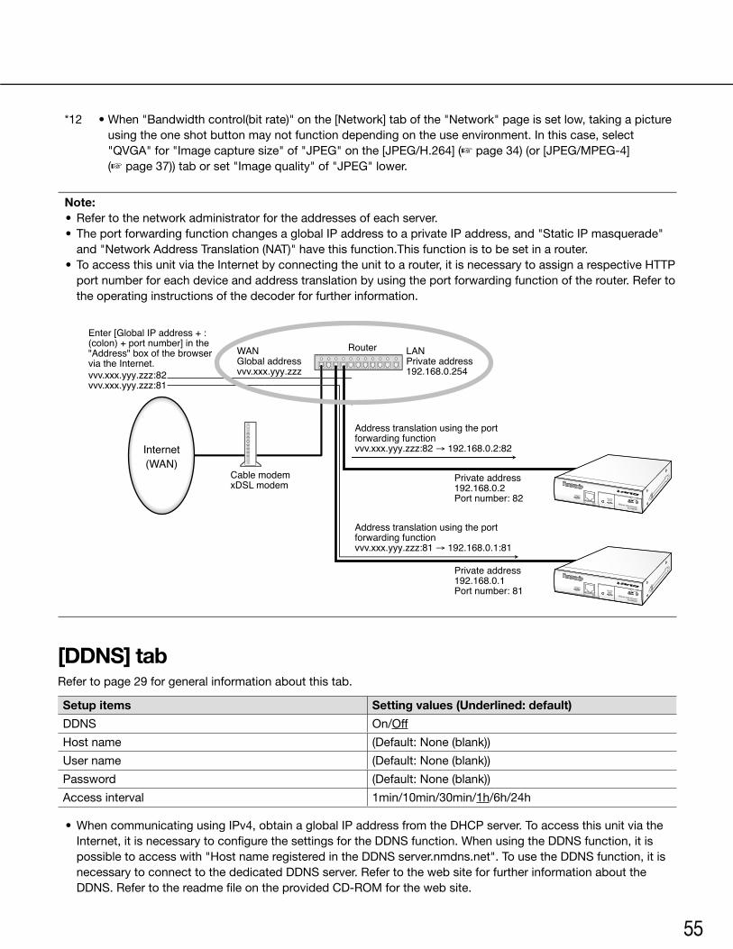
55
*12 •When"Bandwidthcontrol(bitrate)"onthe[Network]tabofthe"Network"pageissetlow,takingapictureusing the one shot button may not function depending on the use environment. In this case, select "QVGA"for"Imagecapturesize"of"JPEG"onthe[JPEG/H.264](☞ page 34) (or [JPEG/MPEG-4] (☞ page 37)) tab or set "Image quality" of "JPEG" lower.
Note: •Refertothenetworkadministratorfortheaddressesofeachserver. • TheportforwardingfunctionchangesaglobalIPaddresstoaprivateIPaddress,and"StaticIPmasquerade"
and "Network Address Translation (NAT)" have this function.This function is to be set in a router. • ToaccessthisunitviatheInternetbyconnectingtheunittoarouter,itisnecessarytoassignarespectiveHTTP
port number for each device and address translation by using the port forwarding function of the router. Refer to the operating instructions of the decoder for further information.
[DDNS] tabRefer to page 29 for general information about this tab.
Setup items Setting values (Underlined: default)
DDNS On/Off
Host name (Default:None(blank))
User name (Default:None(blank))
Password (Default:None(blank))
Access interval 1min/10min/30min/1h/6h/24h
•WhencommunicatingusingIPv4,obtainaglobalIPaddressfromtheDHCPserver.ToaccessthisunitviatheInternet, it is necessary to configure the settings for the DDNS function. When using the DDNS function, it is possible to access with "Host name registered in the DDNS server.nmdns.net". To use the DDNS function, it is necessary to connect to the dedicated DDNS server. Refer to the web site for further information about the DDNS.RefertothereadmefileontheprovidedCD-ROMforthewebsite.
Enter [Global IP address + : (colon) + port number] in the "Address" box of the browser via the Internet.
WANGlobal addressvvv.xxx.yyy.zzz
LANPrivate address192.168.0.254vvv.xxx.yyy.zzz:82
vvv.xxx.yyy.zzz:81
Router
Internet(WAN)
Cable modemxDSL modem
Address translation using the port forwarding functionvvv.xxx.yyy.zzz:82 → 192.168.0.2:82
Address translation using the port forwarding functionvvv.xxx.yyy.zzz:81 → 192.168.0.1:81
Private address192.168.0.2Port number: 82
Private address192.168.0.1Port number: 81
ACT
OPERATE
LINK
SD CARDERROR
Network Video EncoderWJ-GXE500
ACT
OPERATE
LINK
SD CARDERROR
Network Video EncoderWJ-GXE500
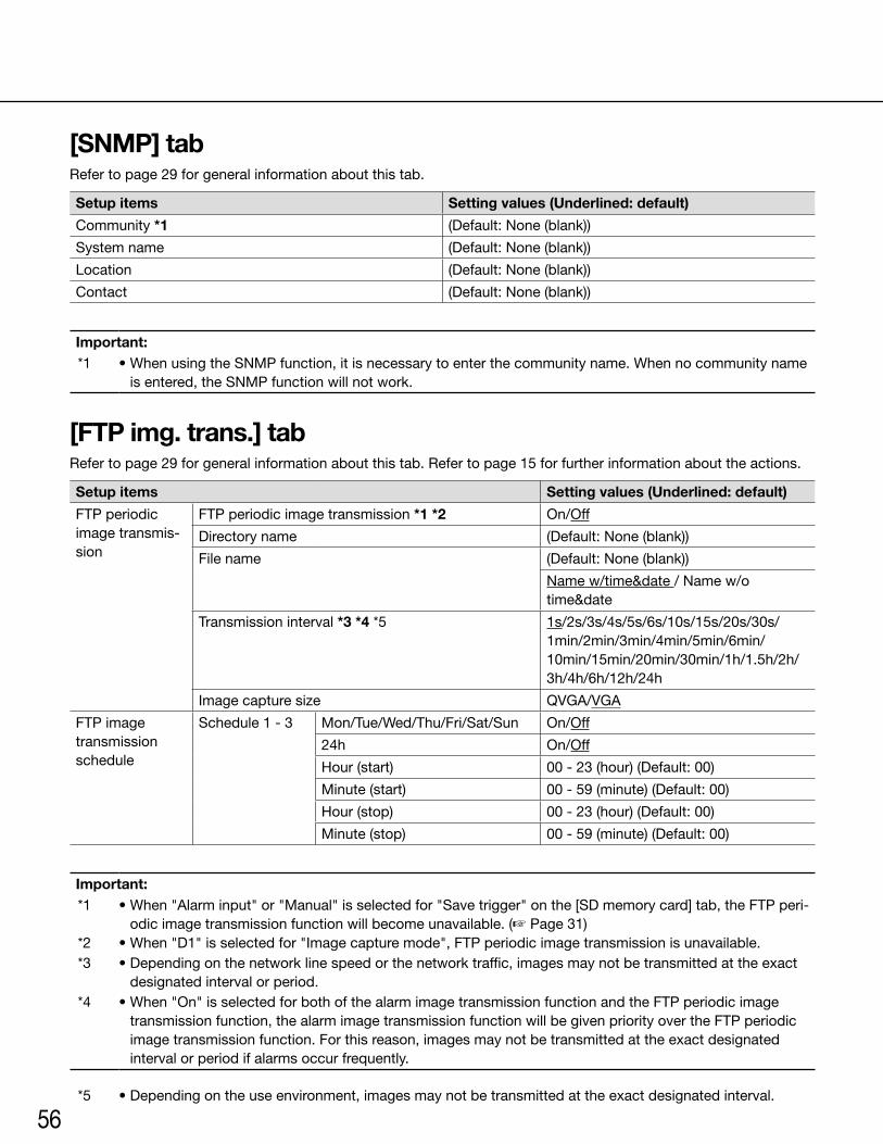
56
[SNMP] tabRefer to page 29 for general information about this tab.
Setup items Setting values (Underlined: default)
Community *1 (Default:None(blank))
System name (Default:None(blank))
Location (Default:None(blank))
Contact (Default:None(blank))
Important:*1 •WhenusingtheSNMPfunction,itisnecessarytoenterthecommunityname.Whennocommunityname
is entered, the SNMP function will not work.
[FTP img. trans.] tabRefer to page 29 for general information about this tab. Refer to page 15 for further information about the actions.
Setup items Setting values (Underlined: default)
FTP periodic image transmis-sion
FTP periodic image transmission *1 *2 On/Off
Directory name (Default:None(blank))
File name (Default:None(blank))
Name w/time&date / Name w/o time&date
Transmission interval *3 *4 *5 1s/2s/3s/4s/5s/6s/10s/15s/20s/30s/ 1min/2min/3min/4min/5min/6min/ 10min/15min/20min/30min/1h/1.5h/2h/ 3h/4h/6h/12h/24h
Imagecapturesize QVGA/VGA
FTP image transmission schedule
Schedule 1 - 3 Mon/Tue/Wed/Thu/Fri/Sat/Sun On/Off
24h On/Off
Hour (start) 00-23(hour)(Default:00)
Minute (start) 00-59(minute)(Default:00)
Hour (stop) 00-23(hour)(Default:00)
Minute (stop) 00-59(minute)(Default:00)
Important:*1 •When"Alarminput"or"Manual"isselectedfor"Savetrigger"onthe[SDmemorycard]tab,theFTPperi-
odic image transmission function will become unavailable. (☞ Page 31)*2 •When"D1"isselectedfor"Imagecapturemode",FTPperiodicimagetransmissionisunavailable.*3 •Dependingonthenetworklinespeedorthenetworktraffic,imagesmaynotbetransmittedattheexact
designated interval or period.*4 •When"On"isselectedforbothofthealarmimagetransmissionfunctionandtheFTPperiodicimage
transmission function, the alarm image transmission function will be given priority over the FTP periodic image transmission function. For this reason, images may not be transmitted at the exact designated interval or period if alarms occur frequently.
*5 •Dependingontheuseenvironment,imagesmaynotbetransmittedattheexactdesignatedinterval.
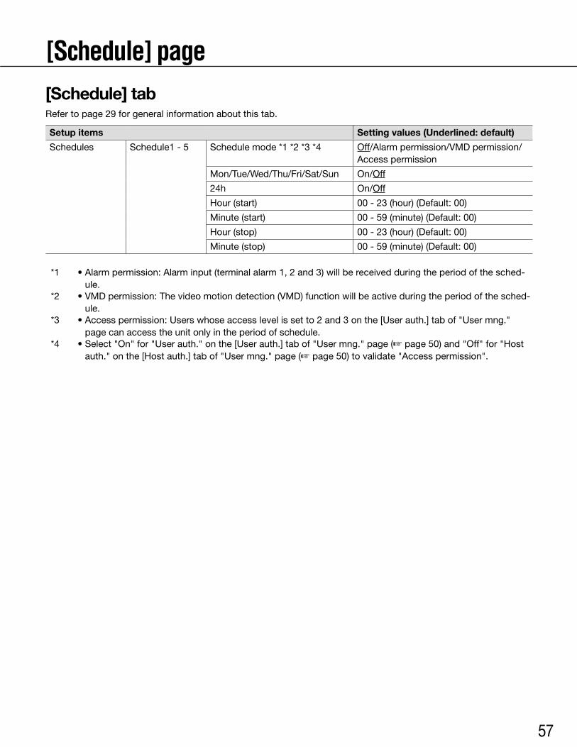
57
[Schedule] page[Schedule] tabRefer to page 29 for general information about this tab.
Setup items Setting values (Underlined: default)
Schedules Schedule1 - 5 Schedule mode *1 *2 *3 *4 Off/Alarm permission/VMD permission/Access permission
Mon/Tue/Wed/Thu/Fri/Sat/Sun On/Off
24h On/Off
Hour (start) 00-23(hour)(Default:00)
Minute (start) 00-59(minute)(Default:00)
Hour (stop) 00-23(hour)(Default:00)
Minute (stop) 00-59(minute)(Default:00)
*1 •Alarmpermission:Alarminput(terminalalarm1,2and3)willbereceivedduringtheperiodofthesched-ule.
*2 •VMDpermission:Thevideomotiondetection(VMD)functionwillbeactiveduringtheperiodofthesched-ule.
*3 •Accesspermission:Userswhoseaccesslevelissetto2and3onthe[Userauth.]tabof"Usermng."page can access the unit only in the period of schedule.
*4 •Select"On"for"Userauth."onthe[Userauth.]tabof"Usermng."page(☞page50)and"Off"for"Hostauth." on the [Host auth.] tab of "User mng." page (☞ page 50) to validate "Access permission".
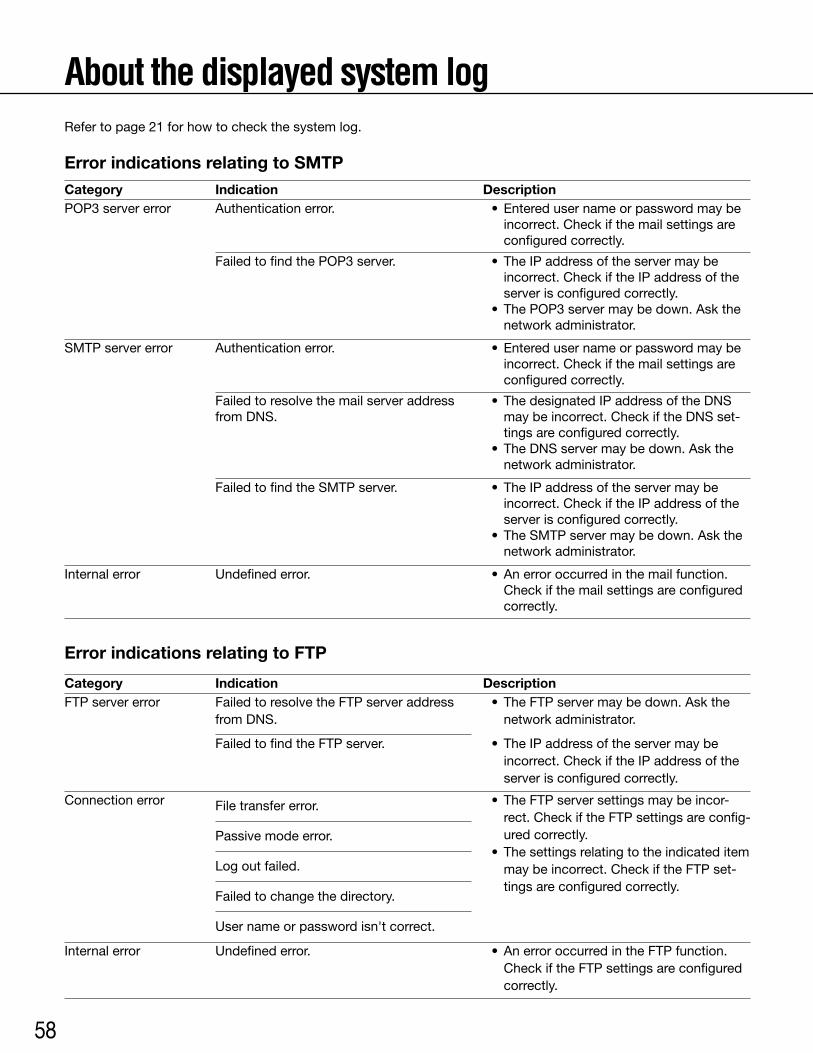
58
About the displayed system logRefer to page 21 for how to check the system log.
Error indications relating to SMTPCategoryPOP3servererror
SMTP server error
Internal error
Authentication error.
FailedtofindthePOP3server.
Authentication error.
Undefined error.
Failed to resolve the mail server address from DNS.
Failed to find the SMTP server.
• Enteredusernameorpasswordmaybeincorrect. Check if the mail settings are configured correctly.
• TheIPaddressoftheservermaybeincorrect. Check if the IP address of the server is configured correctly.
• ThePOP3servermaybedown.Askthenetwork administrator.
• Enteredusernameorpasswordmaybeincorrect. Check if the mail settings are configured correctly.
•Anerroroccurredinthemailfunction.Check if the mail settings are configured correctly.
• ThedesignatedIPaddressoftheDNSmay be incorrect. Check if the DNS set-tings are configured correctly.
• TheDNSservermaybedown.Askthenetwork administrator.
• TheIPaddressoftheservermaybeincorrect. Check if the IP address of the server is configured correctly.
• TheSMTPservermaybedown.Askthenetwork administrator.
Indication Description
CategoryFTP server error
Connection error
Internal error
Failed to resolve the FTP server address from DNS.
Failed to find the FTP server.
File transfer error.
Undefined error.
Passive mode error.
Log out failed.
Failed to change the directory.
User name or password isn't correct.
• TheFTPservermaybedown.Askthenetwork administrator.
• TheFTPserversettingsmaybeincor-rect. Check if the FTP settings are config-ured correctly.
• Thesettingsrelatingtotheindicateditemmay be incorrect. Check if the FTP set-tings are configured correctly.
•AnerroroccurredintheFTPfunction. Check if the FTP settings are configured
correctly.
• TheIPaddressoftheservermaybeincorrect. Check if the IP address of the server is configured correctly.
Indication Description
Error indications relating to FTP
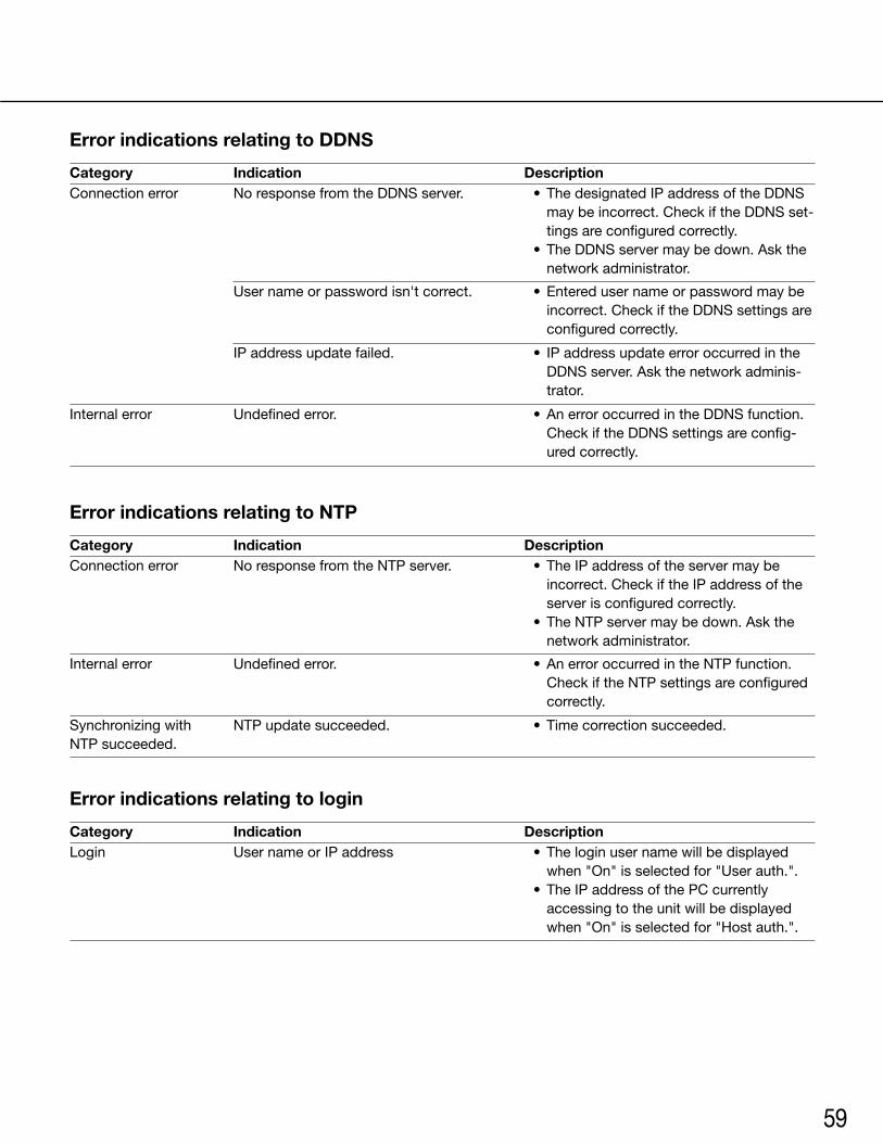
59
CategoryConnection error
Connection error
Login
Synchronizingwith NTP succeeded.
Internal error
Internal error
No response from the DDNS server.
No response from the NTP server.
User name or IP address
NTP update succeeded.
Undefined error.
User name or password isn't correct.
IP address update failed.
Undefined error.
• ThedesignatedIPaddressoftheDDNSmay be incorrect. Check if the DDNS set-tings are configured correctly.
• TheDDNSservermaybedown.Askthenetwork administrator.
• TheIPaddressoftheservermaybeincorrect. Check if the IP address of the server is configured correctly.
• TheNTPservermaybedown.Askthenetwork administrator.
• Theloginusernamewillbedisplayedwhen"On"isselectedfor"Userauth.".
• TheIPaddressofthePCcurrentlyaccessing to the unit will be displayed when"On"isselectedfor"Hostauth.".
• Timecorrectionsucceeded.
•AnerroroccurredintheNTPfunction.Check if the NTP settings are configured correctly.
• Enteredusernameorpasswordmaybeincorrect. Check if the DDNS settings are configured correctly.
• IPaddressupdateerroroccurredintheDDNS server. Ask the network adminis-trator.
•AnerroroccurredintheDDNSfunction.Check if the DDNS settings are config-ured correctly.
Indication Description
Category
Category
Indication
Indication
Description
Description
Error indications relating to DDNS
Error indications relating to NTP
Error indications relating to login
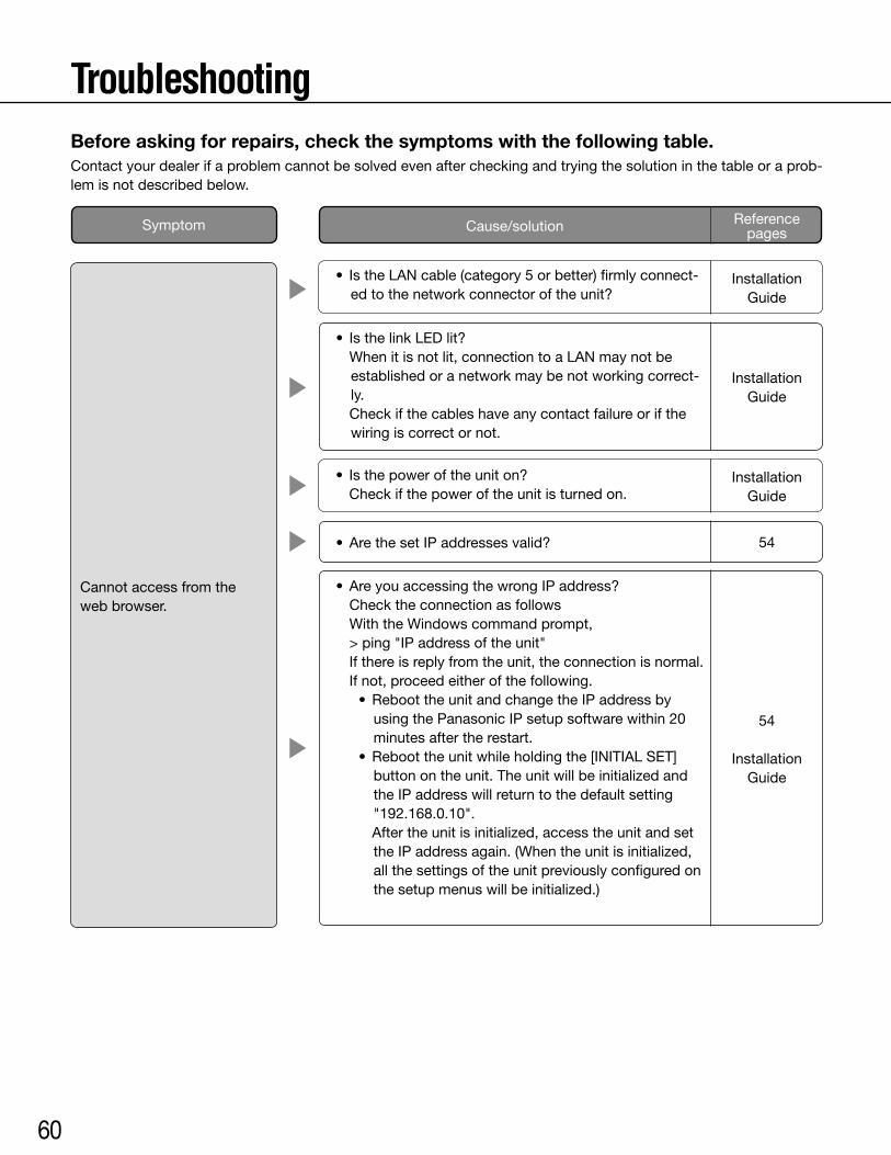
60
•AreyouaccessingthewrongIPaddress? Check the connection as follows With the Windows command prompt, > ping "IP address of the unit" If there is reply from the unit, the connection is normal. If not, proceed either of the following. •ReboottheunitandchangetheIPaddressby
using the Panasonic IP setup software within 20 minutes after the restart.
•Reboottheunitwhileholdingthe[INITIALSET]buttonontheunit.Theunitwillbeinitializedandthe IP address will return to the default setting "192.168.0.10".
Aftertheunitisinitialized,accesstheunitandsettheIPaddressagain.(Whentheunitisinitialized,all the settings of the unit previously configured on thesetupmenuswillbeinitialized.)
54
Installation Guide
TroubleshootingBefore asking for repairs, check the symptoms with the following table.Contact your dealer if a problem cannot be solved even after checking and trying the solution in the table or a prob-lem is not described below.
• Isthepoweroftheuniton? Check if the power of the unit is turned on.
• IstheLANcable(category5orbetter)firmlyconnect-edtothenetworkconnectoroftheunit?
Installation Guide
Installation Guide
•ArethesetIPaddressesvalid?
• IsthelinkLEDlit? When it is not lit, connection to a LAN may not be
established or a network may be not working correct-ly.
Check if the cables have any contact failure or if the wiring is correct or not.
Reference pagesCause/solutionSymptom
Cannot access from the web browser.
Installation Guide
54

61
• Is"Allow"selectedfor"FTPaccesstounit"onthe[Network]tabof"Network"page?
It is necessary in advance to select "Allow" for "FTP access to unit" on the [Network] tab of the "Network" page.
• IstheviewersoftwareinstalledonthePC? Install the viewer software on a PC.
• IstheversionofDirectX9.0corlater? Check the version of DirectX as follows. (1) Select"Run…"fromthestartmenuofWindows. (2) Enter "dxdiag" in the displayed dialog box and
clickthe[OK]button. If the version of DirectX is older than 9.0c, upgrade it.
Cannot obtain images on the SD memory card.
No image is displayed.
Cannot access from the web browser.
54
4
–
• Istheenteredpasswordcorrect? Restart the web browser and enter the password
again.
•AccesstotheSDmemorycardmaybefailed.Restartthe browser and retry to obtain images.
50
–
• IsthesameIPaddressprovidedtootherdevices? Are there contradictions between the address and the
networksubnettobeaccessed? <When the unit and the PC are connected in the same
subnet> Are the IP addresses of the unit and the PC set in a
commonsubnet?Oris"UseProxyServer"fortheset-tingsofthewebbrowserchecked?
When accessing the unit in the same subnet, it is rec-ommended to enter the address of the unit in the "Don’t Use Proxy For These Addresses" box.
<When the unit and the PC are connected in the dif-ferent subnet>
Is the IP address of the default gateway set for the unit correct?
–
Reference pagesCause/solutionSymptom
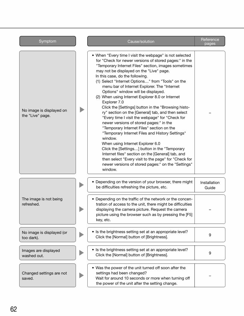
62
Reference pagesCause/solutionSymptom
•When"EverytimeIvisitthewebpage"isnotselectedfor"Checkfornewerversionsofstoredpages:"inthe"Temporary Internet Files" section, images sometimes may not be displayed on the "Live" page.
In this case, do the following. (1) Select"InternetOptions…"from"Tools"onthe
menu bar of Internet Explorer. The "Internet Options"windowwillbedisplayed.
(2) When using Internet Explorer 8.0 or Internet Explorer 7.0
Click the [Settings] button in the "Browsing histo-ry" section on the [General] tab, and then select "Every time I visit the webpage" for "Check for newerversionsofstoredpages:"inthe"Temporary Internet Files" section on the "Temporary Internet Files and History Settings" window.
When using Internet Explorer 6.0 Clickthe[Settings…]buttoninthe"Temporary
Internet files" section on the [General] tab, and then select "Every visit to the page" for "Check for newerversionsofstoredpages:"onthe"Settings"window.
• Isthebrightnesssettingsetatanappropriatelevel? Click the [Normal] button of [Brightness].
•Wasthepoweroftheunitturnedoffsoonafterthesettingshadbeenchanged?
Wait for around 10 seconds or more when turning off the power of the unit after the setting change.
Images are displayed washed out.
Changed settings are not saved.
9
–
• Isthebrightnesssettingsetatanappropriatelevel? Click the [Normal] button of [Brightness].
No image is displayed (or too dark).
9
•Dependingonthetrafficofthenetworkortheconcen-tration of access to the unit, there might be difficulties displaying the camera picture. Request the camera picture using the browser such as by pressing the [F5] key, etc.
–
•Dependingontheversionofyourbrowser,theremightbe difficulties refreshing the picture, etc.
The image is not being refreshed.
Installation Guide
No image is displayed on the "Live" page.
–
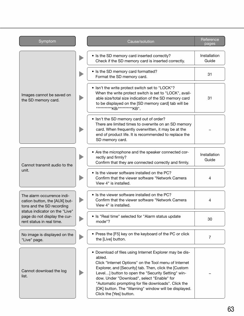
63
• Isn’tthewriteprotectswitchsetto"LOCK"? Whenthewriteprotectswitchissetto"LOCK",avail-
ablesize/totalsizeindicationoftheSDmemorycardto be displayed on the [SD memory card] tab will be "**********KB/**********KB".
• IstheSDmemorycardformatted? Format the SD memory card.
• Is"Realtime"selectedfor"Alarmstatusupdatemode"?
•Pressthe[F5]keyonthekeyboardofthePCorclickthe [Live] button.
30
7
• IstheviewersoftwareinstalledonthePC? Confirm that the viewer software "Network Camera
View 4" is installed.
No image is displayed on the "Live" page.
The alarm occurrence indi-cation button, the [AUX] but-tons and the SD recording status indicator on the "Live" page do not display the cur-rent status in real time.
4
• IstheviewersoftwareinstalledonthePC? Confirm that the viewer software "Network Camera
View 4" is installed.4
•DownloadoffilesusingInternetExplorermaybedis-abled.
Click"InternetOptions"ontheToolmenuofInternetExplorer, and [Security] tab. Then, click the [Custom Level…]buttontoopenthe"SecuritySetting"win-dow. Under "Download", select "Enable" for "Automatic prompting for file downloads". Click the [OK]button.The"Warning"windowwillbedisplayed.
Click the [Yes] button.
Cannot download the log list.
–
•Arethemicrophoneandthespeakerconnectedcor-rectlyandfirmly?
Confirm that they are connected correctly and firmly.Cannot transmit audio to the unit.
Installation Guide
31
31
–
• Isn'ttheSDmemorycardoutoforder? There are limited times to overwrite on an SD memory
card. When frequently overwritten, it may be at the end of product life. It is recommended to replace the SD memory card.
• IstheSDmemorycardinsertedcorrectly? Check if the SD memory card is inserted correctly.
Installation Guide
Images cannot be saved on the SD memory card.
Reference pagesCause/solutionSymptom
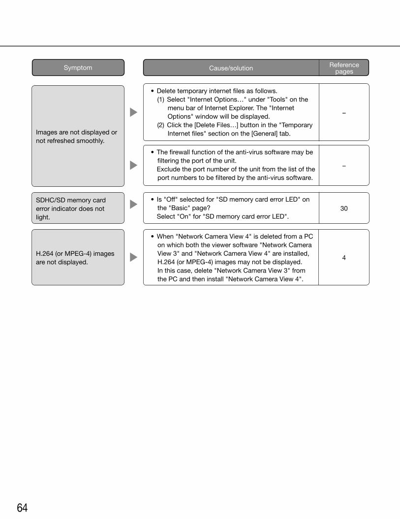
64
•When"NetworkCameraView4"isdeletedfromaPCon which both the viewer software "Network Camera View 3" and "Network Camera View 4" are installed, H.264 (or MPEG-4) images may not be displayed. In this case, delete "Network Camera View 3" from the PC and then install "Network Camera View 4".
Reference pagesCause/solutionSymptom
•Deletetemporaryinternetfilesasfollows. (1) Select"InternetOptions…"under"Tools"onthe
menu bar of Internet Explorer. The "Internet Options"windowwillbedisplayed.
(2)Clickthe[DeleteFiles…]buttoninthe"TemporaryInternet files" section on the [General] tab.
• Thefirewallfunctionoftheanti-virussoftwaremaybefiltering the port of the unit.
Exclude the port number of the unit from the list of the port numbers to be filtered by the anti-virus software.
• Is"Off"selectedfor"SDmemorycarderrorLED"onthe"Basic"page?
Select"On"for"SDmemorycarderrorLED".
Images are not displayed or not refreshed smoothly.
SDHC/SD memory card error indicator does not light.
–
–
30
H.264 (or MPEG-4) images are not displayed.
4
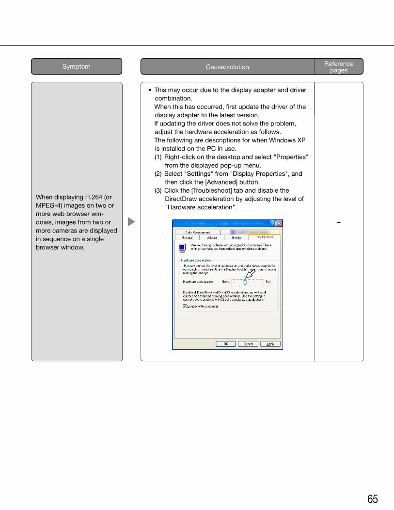
65
• Thismayoccurduetothedisplayadapteranddrivercombination.
When this has occurred, first update the driver of the display adapter to the latest version.
If updating the driver does not solve the problem, adjust the hardware acceleration as follows.
The following are descriptions for when Windows XP is installed on the PC in use.
(1) Right-click on the desktop and select "Properties" from the displayed pop-up menu.
(2) Select "Settings" from "Display Properties", and then click the [Advanced] button.
(3) Click the [Troubleshoot] tab and disable the DirectDraw acceleration by adjusting the level of "Hardware acceleration".
–
When displaying H.264 (or MPEG-4) images on two or more web browser win-dows, images from two or more cameras are displayed in sequence on a single browser window.
Reference pagesCause/solutionSymptom
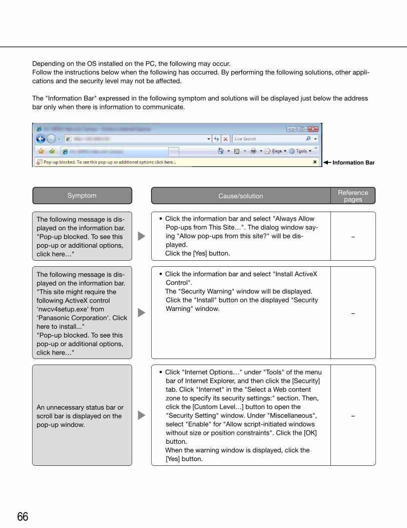
66
Depending on the OS installed on the PC, the following may occur.Follow the instructions below when the following has occurred. By performing the following solutions, other appli-cations and the security level may not be affected.
The "Information Bar" expressed in the following symptom and solutions will be displayed just below the address bar only when there is information to communicate.
•Clicktheinformationbarandselect"AlwaysAllowPop-ups from This Site…". The dialog window say-ing"Allowpop-upsfromthissite?"willbedis-played.
Clickthe[Yes]button.
•Clicktheinformationbarandselect"InstallActiveXControl".
The "Security Warning" window will be displayed. Clickthe"Install"buttononthedisplayed"SecurityWarning" window.
The following message is dis-played on the information bar."Pop-upblocked.Toseethispop-up or additional options, clickhere…"
The following message is dis-played on the information bar."This site might require the followingActiveXcontrol'nwcv4setup.exe' from 'PanasonicCorporation'.Clickhere to install...""Pop-upblocked.Toseethispop-up or additional options, clickhere…"
–
–
Reference pagesCause/solutionSymptom
•Click"InternetOptions…"under"Tools"ofthemenubarofInternetExplorer,andthenclickthe[Security]tab.Click"Internet"inthe"SelectaWebcontentzone to specify its security settings:" section. Then, clickthe[CustomLevel…]buttontoopenthe"Security Setting" window. Under "Miscellaneous", select"Enable"for"Allowscript-initiatedwindowswithoutsizeorpositionconstraints".Clickthe[OK]button.
Whenthewarningwindowisdisplayed,clickthe[Yes]button.
Anunnecessarystatusbarorscroll bar is displayed on the pop-up window.
–
Information Bar
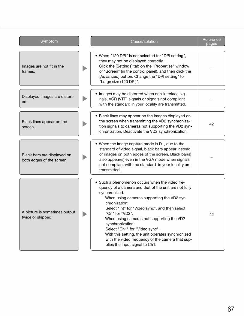
67
•When"120DPI"isnotselectedfor"DPIsetting",they may not be displayed correctly.
Click the [Settings] tab on the "Properties" window of "Screen" (in the control panel), and then click the [Advanced] button. Change the "DPI setting" to "Largesize(120DPI)".
• Imagesmaybedistortedwhennon-interlacesig-nals, VCR (VTR) signals or signals not compliant with the standard in your locality are transmitted.
•BlacklinesmayappearontheimagesdisplayedonthescreenwhentransmittingtheVD2synchroniza-tion signals to cameras not supporting the VD2 syn-chronization.DeactivatetheVD2synchronization.
•WhentheimagecapturemodeisD1,duetothestandard of video signal, black bars appear instead of images on both edges of the screen. Black bar(s) also appear(s) even in the VGA mode when signals not compliant with the standard in your locality are transmitted.
•Suchaphenomenonoccurswhenthevideofre-quency of a camera and that of the unit are not fully synchronized.
When using cameras supporting the VD2 syn-chronization: Select "Int" for "Video sync", and then select "On"for"VD2".
When using cameras not supporting the VD2 synchronization: Select "Ch1" for "Video sync".
Withthissetting,theunitoperatessynchronizedwith the video frequency of the camera that sup-plies the input signal to Ch1.
Images are not fit in the frames.
Displayed images are distort-ed.
Black lines appear on the screen.
Black bars are displayed on both edges of the screen.
A picture is sometimes output twice or skipped.
–
–
42
–
42
Reference pagesCause/solutionSymptom
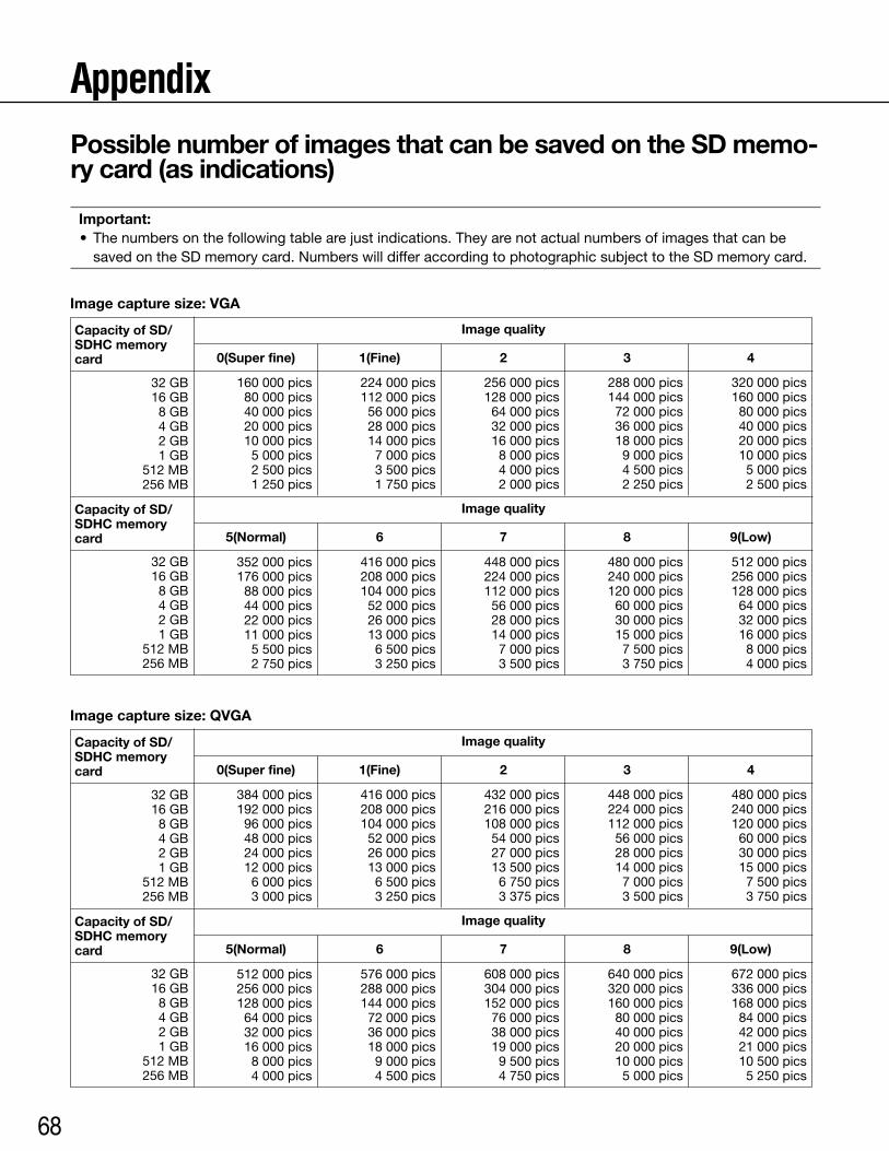
68
Appendix
32 GB16 GB8 GB4 GB2 GB1 GB
512 MB256 MB
32 GB16 GB8 GB4 GB2 GB1 GB
512 MB256 MB
Capacity of SD/SDHC memory card
Capacity of SD/SDHC memory card
Capacity of SD/SDHC memory card
Capacity of SD/SDHC memory card
Possible number of images that can be saved on the SD memo-ry card (as indications)
Important: • Thenumbersonthefollowingtablearejustindications.Theyarenotactualnumbersofimagesthatcanbe
saved on the SD memory card. Numbers will differ according to photographic subject to the SD memory card.
Image capture size: VGA
Image capture size: QVGA
Image quality
Image quality
Image quality
Image quality
352 000 pics176 000 pics88 000 pics44 000 pics22 000 pics11 000 pics5 500 pics2 750 pics
512 000 pics256 000 pics128 000 pics64 000 pics32 000 pics16 000 pics8 000 pics4 000 pics
416 000 pics208 000 pics104 000 pics52 000 pics26 000 pics13 000 pics6 500 pics3 250 pics
576 000 pics288 000 pics144 000 pics72 000 pics36 000 pics18 000 pics9 000 pics4 500 pics
448 000 pics224 000 pics112 000 pics56 000 pics28 000 pics14 000 pics7 000 pics3 500 pics
608 000 pics304 000 pics152 000 pics76 000 pics38 000 pics19 000 pics9 500 pics4 750 pics
480 000 pics240 000 pics120 000 pics60 000 pics30 000 pics15 000 pics7 500 pics3 750 pics
640 000 pics320 000 pics160 000 pics80 000 pics40 000 pics20 000 pics10 000 pics5 000 pics
512 000 pics256 000 pics128 000 pics64 000 pics32 000 pics16 000 pics
8 000 pics4 000 pics
672 000 pics336 000 pics168 000 pics84 000 pics42 000 pics21 000 pics10 500 pics5 250 pics
160 000 pics80 000 pics40 000 pics20 000 pics10 000 pics5 000 pics2 500 pics1 250 pics
384 000 pics192 000 pics96 000 pics48 000 pics24 000 pics12 000 pics6 000 pics3 000 pics
224 000 pics112 000 pics56 000 pics28 000 pics14 000 pics7 000 pics3 500 pics1 750 pics
416 000 pics208 000 pics104 000 pics52 000 pics26 000 pics13 000 pics6 500 pics3 250 pics
256 000 pics128 000 pics64 000 pics32 000 pics16 000 pics8 000 pics4 000 pics2 000 pics
432 000 pics216 000 pics108 000 pics54 000 pics27 000 pics13 500 pics6 750 pics3 375 pics
288 000 pics144 000 pics72 000 pics36 000 pics18 000 pics9 000 pics4 500 pics2 250 pics
448 000 pics224 000 pics112 000 pics56 000 pics28 000 pics14 000 pics7 000 pics3 500 pics
320 000 pics160 000 pics80 000 pics40 000 pics20 000 pics10 000 pics5 000 pics2 500 pics
480 000 pics240 000 pics120 000 pics60 000 pics30 000 pics15 000 pics7 500 pics3 750 pics
32 GB16 GB8 GB4 GB2 GB1 GB
512 MB256 MB
32 GB16 GB8 GB4 GB2 GB1 GB
512 MB256 MB
0(Super fine)
0(Super fine)
5(Normal)
5(Normal)
1(Fine)
1(Fine)
6
6
2
2
7
7
3
3
8
8
4
4
9(Low)
9(Low)
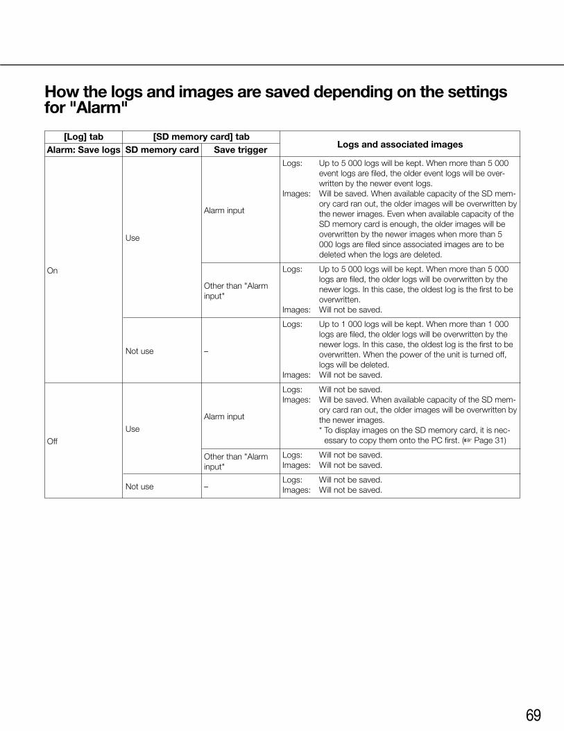
69
How the logs and images are saved depending on the settings for "Alarm"
[Log] tab
Off
Use
Alarm input
Logs: Will not be saved.Images: Will be saved. When available capacity of the SD mem-
ory card ran out, the older images will be overwritten by the newer images. * To display images on the SD memory card, it is nec-
essary to copy them onto the PC first. (☞ Page 31)
On
Alarm: Save logs
Not use
Other than "Alarm input"
–
[SD memory card] tabSD memory card
Use
Not use –
Save trigger
Alarm input
Other than "Alarm input"
Logs: Up to 5 000 logs will be kept. When more than 5 000 event logs are filed, the older event logs will be over-written by the newer event logs.
Images: Will be saved. When available capacity of the SD mem-ory card ran out, the older images will be overwritten by the newer images. Even when available capacity of the SD memory card is enough, the older images will be overwritten by the newer images when more than 5 000 logs are filed since associated images are to be deleted when the logs are deleted.
Logs: Up to 1 000 logs will be kept. When more than 1 000 logs are filed, the older logs will be overwritten by the newer logs. In this case, the oldest log is the first to be overwritten. When the power of the unit is turned off, logs will be deleted.
Images: Will not be saved.
Logs: Will not be saved.Images: Will not be saved.
Logs: Will not be saved.Images: Will not be saved.
Logs: Up to 5 000 logs will be kept. When more than 5 000 logs are filed, the older logs will be overwritten by the newer logs. In this case, the oldest log is the first to be overwritten.
Images: Will not be saved.
Logs and associated images
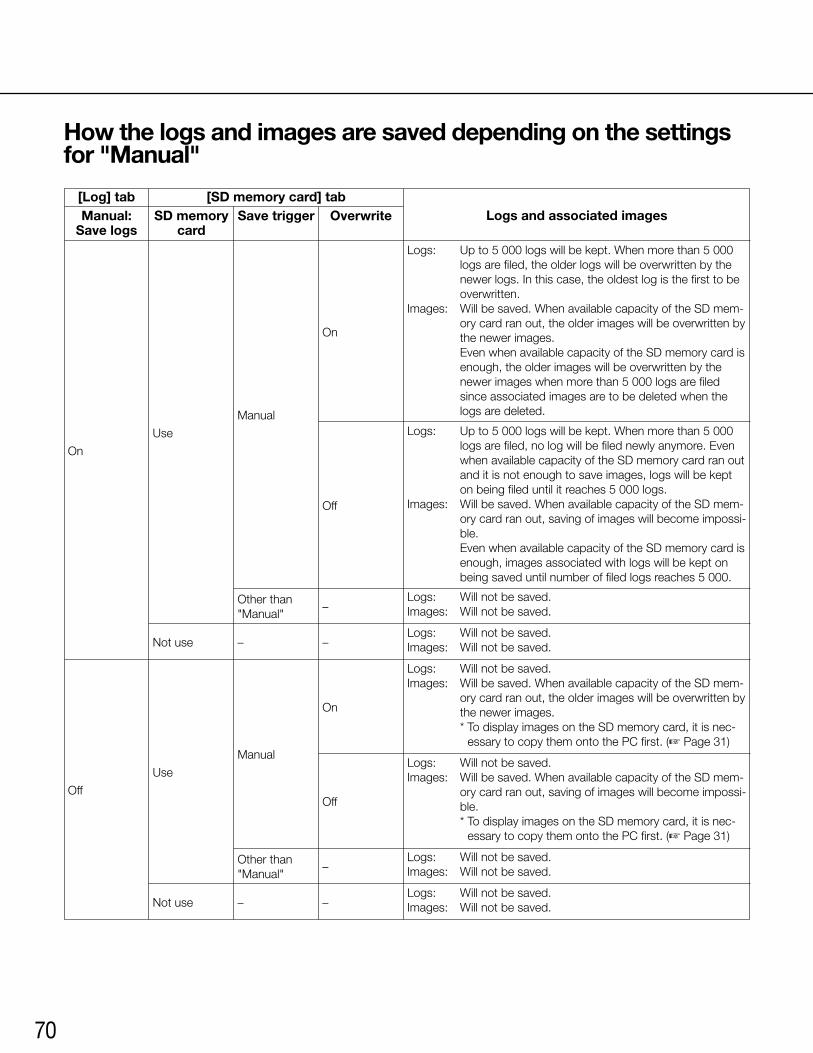
70
How the logs and images are saved depending on the settings for "Manual"
On
Logs and associated imagesManual: Save logs
[Log] tab
Not use
Not use
–
–
–
–
Use
Other than "Manual"
–Logs: Will not be saved.Images: Will not be saved.
Off
Manual
On
Off
[SD memory card] tabSD memory
card
Use
Other than "Manual"
–
Save trigger Overwrite
Manual
On
Off
Logs: Up to 5 000 logs will be kept. When more than 5 000 logs are filed, the older logs will be overwritten by the newer logs. In this case, the oldest log is the first to be overwritten.
Images: Will be saved. When available capacity of the SD mem-ory card ran out, the older images will be overwritten by the newer images.
Even when available capacity of the SD memory card is enough, the older images will be overwritten by the newer images when more than 5 000 logs are filed since associated images are to be deleted when the logs are deleted.
Logs: Will not be saved.Images: Will not be saved.
Logs: Will not be saved.Images: Will not be saved.
Logs: Will not be saved.Images: Will not be saved.
Logs: Will not be saved.Images: Will be saved. When available capacity of the SD mem-
ory card ran out, the older images will be overwritten by the newer images.
* To display images on the SD memory card, it is nec-essary to copy them onto the PC first. (☞ Page 31)
Logs: Will not be saved.Images: Will be saved. When available capacity of the SD mem-
ory card ran out, saving of images will become impossi-ble.
* To display images on the SD memory card, it is nec-essary to copy them onto the PC first. (☞ Page 31)
Logs: Up to 5 000 logs will be kept. When more than 5 000 logs are filed, no log will be filed newly anymore. Even when available capacity of the SD memory card ran out and it is not enough to save images, logs will be kept on being filed until it reaches 5 000 logs.
Images: Will be saved. When available capacity of the SD mem-ory card ran out, saving of images will become impossi-ble.
Even when available capacity of the SD memory card is enough, images associated with logs will be kept on being saved until number of filed logs reaches 5 000.
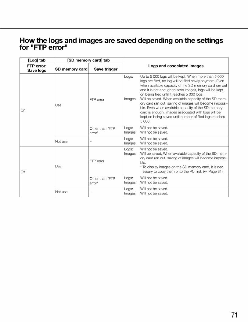
71
How the logs and images are saved depending on the settings for "FTP error"
Logs and associated images[Log] tab
Off
Use
Not use
Other than "FTP error"
–
FTP error
Not use –
Other than "FTP error"
Logs: Will not be saved.Images: Will not be saved.
Logs: Will not be saved.Images: Will be saved. When available capacity of the SD mem-
ory card ran out, saving of images will become impossi-ble.
* To display images on the SD memory card, it is nec-essary to copy them onto the PC first. (☞ Page 31)
Logs: Will not be saved.Images: Will not be saved.
Logs: Will not be saved.Images: Will not be saved.
Logs: Will not be saved.Images: Will not be saved.
On
FTP error: Save logs
[SD memory card] tab
SD memory card
Use
Save trigger
FTP error
Logs: Up to 5 000 logs will be kept. When more than 5 000 logs are filed, no log will be filed newly anymore. Even when available capacity of the SD memory card ran out and it is not enough to save images, logs will be kept on being filed until it reaches 5 000 logs.
Images: Will be saved. When available capacity of the SD mem-ory card ran out, saving of images will become impossi-ble. Even when available capacity of the SD memory card is enough, images associated with logs will be kept on being saved until number of filed logs reaches 5 000.
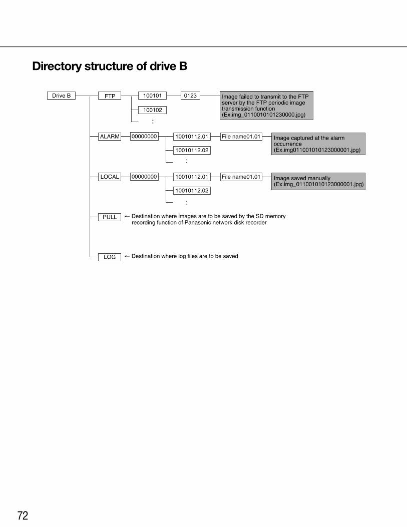
72
Drive B FTP
ALARM
100101
100102
File name01.01
0123
10010112.01
10010112.02
LOCAL
PULL
10010112.01
10010112.02
00000000
00000000
LOG
← Destination where images are to be saved by the SD memory recording function of Panasonic network disk recorder
← Destination where log files are to be saved
File name01.01
Image failed to transmit to the FTP server by the FTP periodic image transmission function(Ex.img_0110010101230000.jpg)
Image captured at the alarm occurrence(Ex.img011001010123000001.jpg)
Image saved manually(Ex.img_011001010123000001.jpg)
Directory structure of drive B

For U.S. and Canada:
Panasonic System Communications Company of North America,Unit of Panasonic Corporation of North Americawww.panasonic.com/business/For customer support, call 1.800.528.6747TwoRiverfrontPlaza,Newark,NJ07102-5490
Panasonic Canada Inc.5770AmblerDrive,Mississauga,Ontario,L4W2T3Canada(905)624-5010www.panasonic.ca
© Panasonic Corporation 2017 N0310-5047 3TR006390FZB Printed in China
For Europe and other countries:
Panasonic Corporationhttp://www.panasonic.com
Panasonic Corporation Osaka,Japan
AuthorisedRepresentativeinEU:
Panasonic Testing CentrePanasonicMarketingEuropeGmbHWinsbergring15,22525Hamburg,Germany